US1069080A - Subsoil attachment for plows. - Google Patents
Subsoil attachment for plows. Download PDFInfo
- Publication number
- US1069080A US1069080A US68944312A US1912689443A US1069080A US 1069080 A US1069080 A US 1069080A US 68944312 A US68944312 A US 68944312A US 1912689443 A US1912689443 A US 1912689443A US 1069080 A US1069080 A US 1069080A
- Authority
- US
- United States
- Prior art keywords
- plows
- base plate
- bracket
- supporting bar
- subsoil
- Prior art date
- Legal status (The legal status is an assumption and is not a legal conclusion. Google has not performed a legal analysis and makes no representation as to the accuracy of the status listed.)
- Expired - Lifetime
Links
Images
Classifications
-
- A—HUMAN NECESSITIES
- A01—AGRICULTURE; FORESTRY; ANIMAL HUSBANDRY; HUNTING; TRAPPING; FISHING
- A01B—SOIL WORKING IN AGRICULTURE OR FORESTRY; PARTS, DETAILS, OR ACCESSORIES OF AGRICULTURAL MACHINES OR IMPLEMENTS, IN GENERAL
- A01B13/00—Ploughs or like machines for special purposes ; Ditch diggers, trench ploughs, forestry ploughs, ploughs for land or marsh reclamation
- A01B13/08—Ploughs or like machines for special purposes ; Ditch diggers, trench ploughs, forestry ploughs, ploughs for land or marsh reclamation for working subsoil
Definitions
- the present invention relates to improve-- ments in. plows, and has particular reference to. subsoil attachments therefor, the main: and: primary object of the invention being to improve the general construction of. subsoil attachments by providing simple and: efiicient means whereby the attachment may be readily applied toplows having standards. or beams of different sizes.
- a further object of the present invention is the provision of a subsoil attachment the construction of which is such that the angularity of the point; may be varied under diflerent. working; conditions to adapt the. attachment for proper action upon the ground
- Figure l is a perspective view of a plow provided with a subsoil attachment embodying the present invention.
- F ig- 2 is a detail perspective view of the: clamp. and the base plate.
- Fig. 3 is a similar view of the supporting bracket for the point.
- Fig. at is a side elevation thereof.
- Fig. 5. is a detail perspective view of a form of point which may be employed with the present invention.
- the numeral 10 designates a furrowing plow ofordinary construction, this being illustrated as embodying a beam and standard as formed in an integral structure.
- the particular construction. of the plow 10 has nothing to do with the present invention,.the latter residing in the construction of a subsoil attachment as'previously stated.
- This attachment includes a base plate 11 provided with upwardly and downwardly projecting wings 12 and 13, respectively, which wings are arranged in unalined vertical planes on the plate 11, and each is provided with an opening 14 for the reception of fastening bolts, as will be presently stated.
- each of the sections 15 comprise an attachingflange 16 which bears upon the base plate 11, said flanges having a plurality of slots 17 which receive bolts 18, or their equivalent.
- the clevis sections 15 are adjustably mounted on the plate 11, and may be moved toward and away from each other for the purpose of accommodating therebetween plow standards of different sizes.
- Each of the sections 15, at the side thereof opposite tothe attaching flange 16, has an outwardly extending clamping flange 19, the flanges of both the sections 15, when assembled upon the plate 11, being parallel and having alined openings 20 formed therein for the reception of suitable fastening bolts 21. It will thus be seen that with the clamp sections 15 properly adjusted in relation. to each other in accordance with the size of the plow standard, and the fastening bolts 21 arranged in the clamping flanges 19, the base plate 11 is held firmly upon the standard.
- a supporting bar 22 Associated with the base plate 11 is a supporting bar 22, said bar being provided with a. series of perforations 23 and a pair of bolts 24: are passed, through two of said perforations and through the openings 14 in the Wings 12 and. 13, one of said bolts 24 being shown in Fig. 1 thereby holding the supporting bar 22 upon the base plate.
- the openings 14 are diagonally opposite, and thus the supporting bar 22, when applied to the base plate 11, is held in an inclined position thereon.
- the lower end of the bar 22 has a curved foot 25 and pivotally mounted on said foot 25 is an angular supporting bracket 26.
- the pivotal connection of the bracket 26 is aii'orded by a bolt 27 which passes through the guide of said bracket,
- said guide is also provided with an arcuate slot 28 which is concentric with the bolt 27, a clamping bolt 29 passing through the slot 28 and the foot 25, and holding the supporting bracket 26 in various positions of adjustment thereon.
- the slots 31 permit longitudinal adjustment of the point on the supporting bracket 26, and the slot 28 and bolt 29 also aiford angular adjustment of the bracket 26 whereby the pitch thereof may be varied, and thus enable the point to enter the ground at a greater or less angle.
- the hereindescribed invention is adaptable for use with furrowing plows having varying sizes of standards or beams, and with the clamp sections 15 clamped thereon, the base plate 11 is held in fixed position for maintaining the supporting bar 22 in proper relation to the beam.
- the supporting bar 22 may be adjusted upwardly or downwardly, thus varying the depth at which the point 33 enters the subsoil, and by adjusting the bolt 29 the supporting bracket 26 may also be changed in its angular relation to the foot 25, and thereby change the angular position of the point 33.
- the point 33 is appropriately notched as at 35 and 36 for fitting about the curved foot 25 and the colter at, the supporting bracket 26 being also provided with an opening 37 through which the colter 34: passes.
- a subsoil attachment for plows comprising a base plate, adjustable clamp sections mounted thereon, a supporting bar mounted upon said base plate, and a point suitably connected to said supporting bar.
- a subsoil attachment for plows comprising a base plate, means for attaching the same to a plow, a supporting bar mounted in diagonal relation to said base plate, and a point carried by said supporting bar.
- a subsoil attachment for plows comprising a base plate provided with oppositely extending unalined wings, means for attaching the base plate to a plow, a supporting bar extending across said wings, and held thereby in diagonal relation to said base plate, and a point carried by said supporting bar.
- a subsoil attachment for plows com prising a base plate, adjustable clamp sections carried by said base plate for attaching the latter to a plow, each of said sections including a base flange, a clamping flange, and means for holding the clamping flanges in associated relation, a supporting bar mounted upon said base plate, and a point carried by said supportingb'arQ 5.
- a subsoil attachment for plows comprising a supporting bar, means for attaching the same to a plow, an attaching bracket adjustably mounted upon said supporting bar, a point carried by said bracket, and means for adjusting said bracket upon said supporting bar to vary the pitch of said point.
- a supporting bar prising a supporting bar, means for attaching the same to a plow, a supporting bracket associated with said supporting bar and provided with a guide and plate arranged in angular relation to each other, a point carried by the plate of saidbracket, means for pivoting the guide of the bracket to said supporting bar, and means for permitting adjustment of said supporting bracket in relation to the supporting bar to vary the pitch of said point.
- a subsoil attachment for plows comprising a supporting bar, an attaching bracket associated therewith and including a plate and a guide arranged in angular relation to each other, means for adjustably connecting said attaching bracket to said supporting bar, and a point mounted upon the plate of said supporting bracket and adjustably connected thereto.
Landscapes
- Life Sciences & Earth Sciences (AREA)
- Engineering & Computer Science (AREA)
- Mechanical Engineering (AREA)
- Soil Sciences (AREA)
- Environmental Sciences (AREA)
- Soil Working Implements (AREA)
- Agricultural Machines (AREA)
Description
B. L. BISHOP.
SUBSOIL ATTACHMENT FOR FLOWS.
v APPLICATION FILED APILB, 1912. 1,069,080.
Patented July 29, 1913.
BEN L. BISHOP, OF JACKSON, TENNESSEE.
SUBSOIL ATTACHMENT FOR PLOWS.
Specification of Letters Patent.
Patented July 29, 1913.
Application filed April 8, 1912. Serial No. 689,443.
To all whom z'tmay concern:
Be. it known that I, BEN L. BISHOP, a citizen. of the United. States, residing at Jackson, in thecounty of Madison and State of Tennessee, have invented certain new and useful Improvements in Subso-il Attachments for Plows, of which the following is a. specification.
The present invention relates to improve-- ments in. plows, and has particular reference to. subsoil attachments therefor, the main: and: primary object of the invention being to improve the general construction of. subsoil attachments by providing simple and: efiicient means whereby the attachment may be readily applied toplows having standards. or beams of different sizes.
A further object of the present invention is the provision of a subsoil attachment the construction of which is such that the angularity of the point; may be varied under diflerent. working; conditions to adapt the. attachment for proper action upon the ground With these general objects in view, and others. which wilh appear as the nature of the improvements is better. understood, the invention consists substantially in the novel construction, combination, and arrangement of parts hereinafter fully described, illustrated: in the accompanying, drawings, and pointed out in the appended claims.
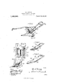
In the drawings Figure l is a perspective view of a plow provided with a subsoil attachment embodying the present invention. F ig- 2 is a detail perspective view of the: clamp. and the base plate. Fig. 3 is a similar view of the supporting bracket for the point. Fig. at is a side elevation thereof. Fig. 5. is a detail perspective view of a form of point which may be employed with the present invention.
Referring in detail; to the accompanying drawings, the numeral 10 designates a furrowing plow ofordinary construction, this being illustrated as embodying a beam and standard as formed in an integral structure. The particular construction. of the plow 10, however, has nothing to do with the present invention,.the latter residing in the construction of a subsoil attachment as'previously stated. This attachment includes a base plate 11 provided with upwardly and downwardly projecting wings 12 and 13, respectively, which wings are arranged in unalined vertical planes on the plate 11, and each is provided with an opening 14 for the reception of fastening bolts, as will be presently stated. Mounted upon the base plate 11 is a pair of adjustable clamp seotions15, each of which is a complement of the other, but the parts of one are reversed to the parts of the other. Each of the sections 15 comprise an attachingflange 16 which bears upon the base plate 11, said flanges having a plurality of slots 17 which receive bolts 18, or their equivalent. By reason of the slots 17 and bolts 18 the clevis sections 15 are adjustably mounted on the plate 11, and may be moved toward and away from each other for the purpose of accommodating therebetween plow standards of different sizes. Each of the sections 15, at the side thereof opposite tothe attaching flange 16, has an outwardly extending clamping flange 19, the flanges of both the sections 15, when assembled upon the plate 11, being parallel and having alined openings 20 formed therein for the reception of suitable fastening bolts 21. It will thus be seen that with the clamp sections 15 properly adjusted in relation. to each other in accordance with the size of the plow standard, and the fastening bolts 21 arranged in the clamping flanges 19, the base plate 11 is held firmly upon the standard.
Associated with the base plate 11 is a supporting bar 22, said bar being provided with a. series of perforations 23 and a pair of bolts 24: are passed, through two of said perforations and through the openings 14 in the Wings 12 and. 13, one of said bolts 24 being shown in Fig. 1 thereby holding the supporting bar 22 upon the base plate. It will be noted from Fig. 2 that the openings 14 are diagonally opposite, and thus the supporting bar 22, when applied to the base plate 11, is held in an inclined position thereon. The lower end of the bar 22 has a curved foot 25 and pivotally mounted on said foot 25 is an angular supporting bracket 26. The pivotal connection of the bracket 26 is aii'orded by a bolt 27 which passes through the guide of said bracket,
and said guide is also provided with an arcuate slot 28 which is concentric with the bolt 27, a clamping bolt 29 passing through the slot 28 and the foot 25, and holding the supporting bracket 26 in various positions of adjustment thereon. The plate of the 33 on the bracket 26. The slots 31 permit longitudinal adjustment of the point on the supporting bracket 26, and the slot 28 and bolt 29 also aiford angular adjustment of the bracket 26 whereby the pitch thereof may be varied, and thus enable the point to enter the ground at a greater or less angle.
Extending across the foot 25 is a colter 3a,
the upper end of which is suitably connected to the upper portion of said foot, while its lower end is suitably connected to the supporting bracket 26.
From the foregoing description, it will be seen that the hereindescribed invention is adaptable for use with furrowing plows having varying sizes of standards or beams, and with the clamp sections 15 clamped thereon, the base plate 11 is held in fixed position for maintaining the supporting bar 22 in proper relation to the beam. Through the medium of the openings 23 the supporting bar 22 may be adjusted upwardly or downwardly, thus varying the depth at which the point 33 enters the subsoil, and by adjusting the bolt 29 the supporting bracket 26 may also be changed in its angular relation to the foot 25, and thereby change the angular position of the point 33. It will be observed that the point 33 is appropriately notched as at 35 and 36 for fitting about the curved foot 25 and the colter at, the supporting bracket 26 being also provided with an opening 37 through which the colter 34: passes.
Having thus described the invention, what is claimed as new, and desired to be secured by Letters Patent, is
1. A subsoil attachment for plows, comprising a base plate, adjustable clamp sections mounted thereon, a supporting bar mounted upon said base plate, and a point suitably connected to said supporting bar.
2. A subsoil attachment for plows, comprising a base plate, means for attaching the same to a plow, a supporting bar mounted in diagonal relation to said base plate, and a point carried by said supporting bar.
3. A subsoil attachment for plows, comprising a base plate provided with oppositely extending unalined wings, means for attaching the base plate to a plow, a supporting bar extending across said wings, and held thereby in diagonal relation to said base plate, and a point carried by said supporting bar.
t. A subsoil attachment for plows, com prising a base plate, adjustable clamp sections carried by said base plate for attaching the latter to a plow, each of said sections including a base flange, a clamping flange, and means for holding the clamping flanges in associated relation, a supporting bar mounted upon said base plate, and a point carried by said supportingb'arQ 5. A subsoil attachment for plows, comprising a supporting bar, means for attaching the same to a plow, an attaching bracket adjustably mounted upon said supporting bar, a point carried by said bracket, and means for adjusting said bracket upon said supporting bar to vary the pitch of said point.
-6. A subsoil attachment for plows, com-. 7
prising a supporting bar, means for attaching the same to a plow, a supporting bracket associated with said supporting bar and provided with a guide and plate arranged in angular relation to each other, a point carried by the plate of saidbracket, means for pivoting the guide of the bracket to said supporting bar, and means for permitting adjustment of said supporting bracket in relation to the supporting bar to vary the pitch of said point.
7 A subsoil attachment for plows, comprising a supporting bar, an attaching bracket associated therewith and including a plate and a guide arranged in angular relation to each other, means for adjustably connecting said attaching bracket to said supporting bar, and a point mounted upon the plate of said supporting bracket and adjustably connected thereto.
8. The combination with a plow standard of a clip embracing the standard and provided with spaced openings located upon a line at an angle to a vertical, a bar having openings spaced to register with the openings of the clip and extending rearwardly of the standard, a subsoil shoe adjustably connected at the end of the bar and disposed at an inclination to a horizontal, and a brace extending from the bar toward the forward end of the shoe.
In testimony whereof I aflix my signature in presence of two witnesses.
M. B. HUNT, B. G. RIPLEY.
Copies of this patent may be obtained for five cents each, by addressing the Commissioner of Patents, Washington, D. C.
Priority Applications (1)
| Application Number | Priority Date | Filing Date | Title |
|---|---|---|---|
| US68944312A US1069080A (en) | 1912-04-08 | 1912-04-08 | Subsoil attachment for plows. |
Applications Claiming Priority (1)
| Application Number | Priority Date | Filing Date | Title |
|---|---|---|---|
| US68944312A US1069080A (en) | 1912-04-08 | 1912-04-08 | Subsoil attachment for plows. |
Publications (1)
| Publication Number | Publication Date |
|---|---|
| US1069080A true US1069080A (en) | 1913-07-29 |
Family
ID=3137318
Family Applications (1)
| Application Number | Title | Priority Date | Filing Date |
|---|---|---|---|
| US68944312A Expired - Lifetime US1069080A (en) | 1912-04-08 | 1912-04-08 | Subsoil attachment for plows. |
Country Status (1)
| Country | Link |
|---|---|
| US (1) | US1069080A (en) |
-
1912
- 1912-04-08 US US68944312A patent/US1069080A/en not_active Expired - Lifetime
Similar Documents
| Publication | Publication Date | Title |
|---|---|---|
| US1069080A (en) | Subsoil attachment for plows. | |
| US1032291A (en) | Adjustable scraper. | |
| US215587A (en) | Improvement in colter and jointer | |
| US965121A (en) | Plow. | |
| US663494A (en) | Fender attachment for cultivator-plows. | |
| US227687A (en) | Cultivator | |
| US1004387A (en) | Plow. | |
| US860894A (en) | Reversible-disk plow. | |
| US549215A (en) | Vernon eli sapp | |
| US540711A (en) | John c | |
| US662081A (en) | Cultivating-plow. | |
| US566528A (en) | Double-shovel plow | |
| US190510A (en) | Improvement in colter or jointer supporters for plows | |
| US567220A (en) | carroll | |
| US796225A (en) | Plow-colter. | |
| US760767A (en) | Plow. | |
| US847196A (en) | Plow. | |
| US206639A (en) | Improvement in plows | |
| US370808A (en) | Chison | |
| US554087A (en) | Attachment for cultivators | |
| US422418A (en) | John w | |
| US962508A (en) | Colter-fastening. | |
| US736503A (en) | Plow. | |
| US334106A (en) | Joseph m | |
| US376008A (en) | Cultivator |