US10690155B2 - Actuator - Google Patents
Actuator Download PDFInfo
- Publication number
- US10690155B2 US10690155B2 US16/277,134 US201916277134A US10690155B2 US 10690155 B2 US10690155 B2 US 10690155B2 US 201916277134 A US201916277134 A US 201916277134A US 10690155 B2 US10690155 B2 US 10690155B2
- Authority
- US
- United States
- Prior art keywords
- muscle
- rotation member
- artificial
- actuator
- artificial muscles
- Prior art date
- Legal status (The legal status is an assumption and is not a legal conclusion. Google has not performed a legal analysis and makes no representation as to the accuracy of the status listed.)
- Active
Links
Images




Classifications
-
- B—PERFORMING OPERATIONS; TRANSPORTING
- B25—HAND TOOLS; PORTABLE POWER-DRIVEN TOOLS; MANIPULATORS
- B25J—MANIPULATORS; CHAMBERS PROVIDED WITH MANIPULATION DEVICES
- B25J9/00—Program-controlled manipulators
- B25J9/10—Program-controlled manipulators characterised by positioning means for manipulator elements
- B25J9/14—Program-controlled manipulators characterised by positioning means for manipulator elements fluid
- B25J9/142—Program-controlled manipulators characterised by positioning means for manipulator elements fluid comprising inflatable bodies
-
- B—PERFORMING OPERATIONS; TRANSPORTING
- B25—HAND TOOLS; PORTABLE POWER-DRIVEN TOOLS; MANIPULATORS
- B25J—MANIPULATORS; CHAMBERS PROVIDED WITH MANIPULATION DEVICES
- B25J9/00—Program-controlled manipulators
- B25J9/10—Program-controlled manipulators characterised by positioning means for manipulator elements
- B25J9/14—Program-controlled manipulators characterised by positioning means for manipulator elements fluid
- B25J9/146—Rotary actuators
-
- F—MECHANICAL ENGINEERING; LIGHTING; HEATING; WEAPONS; BLASTING
- F15—FLUID-PRESSURE ACTUATORS; HYDRAULICS OR PNEUMATICS IN GENERAL
- F15B—SYSTEMS ACTING BY MEANS OF FLUIDS IN GENERAL; FLUID-PRESSURE ACTUATORS, e.g. SERVOMOTORS; DETAILS OF FLUID-PRESSURE SYSTEMS, NOT OTHERWISE PROVIDED FOR
- F15B15/00—Fluid-actuated devices for displacing a member from one position to another; Gearing associated therewith
- F15B15/02—Mechanical layout characterised by the means for converting the movement of the fluid-actuated element into movement of the finally-operated member
-
- F—MECHANICAL ENGINEERING; LIGHTING; HEATING; WEAPONS; BLASTING
- F15—FLUID-PRESSURE ACTUATORS; HYDRAULICS OR PNEUMATICS IN GENERAL
- F15B—SYSTEMS ACTING BY MEANS OF FLUIDS IN GENERAL; FLUID-PRESSURE ACTUATORS, e.g. SERVOMOTORS; DETAILS OF FLUID-PRESSURE SYSTEMS, NOT OTHERWISE PROVIDED FOR
- F15B15/00—Fluid-actuated devices for displacing a member from one position to another; Gearing associated therewith
- F15B15/02—Mechanical layout characterised by the means for converting the movement of the fluid-actuated element into movement of the finally-operated member
- F15B15/06—Mechanical layout characterised by the means for converting the movement of the fluid-actuated element into movement of the finally-operated member for mechanically converting rectilinear movement into non- rectilinear movement
-
- F—MECHANICAL ENGINEERING; LIGHTING; HEATING; WEAPONS; BLASTING
- F15—FLUID-PRESSURE ACTUATORS; HYDRAULICS OR PNEUMATICS IN GENERAL
- F15B—SYSTEMS ACTING BY MEANS OF FLUIDS IN GENERAL; FLUID-PRESSURE ACTUATORS, e.g. SERVOMOTORS; DETAILS OF FLUID-PRESSURE SYSTEMS, NOT OTHERWISE PROVIDED FOR
- F15B15/00—Fluid-actuated devices for displacing a member from one position to another; Gearing associated therewith
- F15B15/08—Characterised by the construction of the motor unit
- F15B15/10—Characterised by the construction of the motor unit the motor being of diaphragm type
- F15B15/103—Characterised by the construction of the motor unit the motor being of diaphragm type using inflatable bodies that contract when fluid pressure is applied, e.g. pneumatic artificial muscles or McKibben-type actuators
-
- B—PERFORMING OPERATIONS; TRANSPORTING
- B25—HAND TOOLS; PORTABLE POWER-DRIVEN TOOLS; MANIPULATORS
- B25J—MANIPULATORS; CHAMBERS PROVIDED WITH MANIPULATION DEVICES
- B25J9/00—Program-controlled manipulators
- B25J9/10—Program-controlled manipulators characterised by positioning means for manipulator elements
- B25J9/1075—Program-controlled manipulators characterised by positioning means for manipulator elements with muscles or tendons
-
- F—MECHANICAL ENGINEERING; LIGHTING; HEATING; WEAPONS; BLASTING
- F15—FLUID-PRESSURE ACTUATORS; HYDRAULICS OR PNEUMATICS IN GENERAL
- F15B—SYSTEMS ACTING BY MEANS OF FLUIDS IN GENERAL; FLUID-PRESSURE ACTUATORS, e.g. SERVOMOTORS; DETAILS OF FLUID-PRESSURE SYSTEMS, NOT OTHERWISE PROVIDED FOR
- F15B2215/00—Fluid-actuated devices for displacing a member from one position to another
- F15B2215/30—Constructional details thereof
Definitions
- Embodiments described herein relate generally to an actuator.
- An actuator that carries out rotation of a flexible joint by using artificial muscles is known.
- artificial muscles respectively functioning as an agonist muscle and an antagonist muscle are placed in parallel to each other as a pair, and a wire connected to the agonist muscle and a wire connected to the antagonist muscle are wound around a rotation shaft in a mutually-opposing manner and fixed to the shaft. If the contraction force of the agonist muscle is greater than the contraction force of the antagonist muscle, the agonist muscle contracts greater than the antagonist muscle, and the rotation shaft is rotated toward the side where the agonist muscle is attached. If, on the other hand, the contraction force of the antagonist muscle is greater than the contraction force of the agonist muscle, the agonist muscle contracts greater than the agonist muscle, and the rotation shaft is rotated toward the side where the antagonist muscle is attached.
- FIG. 1 is a diagram of an actuator according to an embodiment.
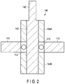
- FIG. 2 is a vertical cross-sectional diagram illustrating the actuator shown in FIG. 1 .
- FIG. 3 is a perspective view of a base shown in FIG. 1 .
- FIG. 4 is a diagram of a fluid flow path shown in FIG. 1 .
- FIG. 5 is a diagram of the main part of an alternative actuator according to an embodiment.
- FIG. 6 is an overall diagram of the alternative actuator according to the embodiment.
- FIG. 7 is a diagram showing the relationship among a length 11 of an agonist muscle, a length 12 of an antagonist muscle, a natural length L 0 of the agonist or antagonist muscle, and an attachment length L of the agonist or antagonist muscle in the actuator shown in FIGS. 1 to 6 .
- FIG. 8 is a diagram of a pressure adjusting mechanism of artificial muscles for driving the actuator shown in FIG. 6 .
- FIG. 9 is a diagram of a triaxial arm robot in which actuators each shown in FIG. 6 are installed.
- An actuator includes a base to which first and second fluid couplings are fixed, a rotation member rotatably supported by the base, and McKibben-type first and second artificial muscles wound around the rotation member.
- the first and second artificial muscles are arranged in an antagonistic manner. One ends of the first and second artificial muscles are fixed to the rotation member. The other ends of the first and second artificial muscles are respectively connected to the first and second fluid couplings.
- FIG. 1 is a diagram of an actuator 100 according to an embodiment.
- FIG. 2 is a vertical cross-sectional diagram illustrating the actuator 100 shown in FIG. 1 .
- FIG. 3 is a perspective view of a base shown in FIG. 1 .
- FIG. 4 is a diagram of a fluid flow path shown in FIG. 3 .
- the actuator 100 is an actuator for flexible joints.
- Flexible joints herein refer to joints that have flexibility in joint movements. In other words, although they are fixed at a certain angle, flexible joints can move in response to an external force.
- the actuator 100 comprises a base 110 , a rotation member 140 rotatably supported by the base 110 , and a pair of McKibben-type artificial muscles 162 A and 162 B wound around the rotation member 140 .
- the base 110 has a shape of a disc in appearance.
- the rotation member 140 has a main body 144 and a rotation shaft 142 projecting from the main body 144 . Both of the main body 144 and the rotation shaft 142 have a shape of a column in appearance.
- the rotation member 140 is attached to the base 110 with a bearing 112 being interposed therebetween.
- the rotation member 140 includes a core member 152 having the rotation shaft 142 , and a pair of sleeves 154 A and 154 B placed around the core member 152 .
- the sleeves 154 A and 154 B are stationarily fixed to the core member 152 , sandwiching the bearing 112 therebetween.
- the structure of the rotation member 140 shown in FIG. 2 is merely an example, and the structure is not limited thereto.
- the diameter of the main body 144 of the rotating member 140 is reduced in the part where the bearing 112 of the base 110 is located; however, the embodiment is not limited to this example, and the main body 144 may have a cylindrical body having a constant diameter.
- Each of the McKibben-type artificial muscles 162 A and 162 B has a tubular structure through which a fluid, for example air, can flow inside, and expands and contracts as a pressure of the fluid flowing inside changes.
- a fluid for example air
- the McKibben-type artificial muscles 162 A and 162 B contract in an axial direction, thickening in a diameter direction as the pressure of the fluid inside increases.
- the McKibben-type artificial muscles 162 A and 162 B extend in an axial direction, thinning in a diameter direction so as to return to their original shapes.
- the pair of artificial muscles 162 A and 162 B is arranged in an antagonistic manner.
- the artificial muscles 162 A and 162 B are wound around the main body 144 of the rotation member 140 in mutually-opposite directions.
- the artificial muscle 162 A is spirally wound around the rotation member 140 in a first circumferential direction.
- the artificial muscle 162 B is spirally wound around the rotation member 140 in a second circumferential direction that is opposite to the first circumferential direction.
- the first circumferential direction and the second circumferential direction are directions along a circumference located on a peripheral surface of the main body 144 of the rotation member 140 .
- the first circumferential direction is a clockwise direction
- the second circumferential direction is a counterclockwise direction.
- One ends or first ends of the artificial muscles 162 A and 162 B are respectively fixed to the main body 144 of the rotation member 140 by stoppers 164 A and 164 B.
- the other ends or second ends of the artificial muscles 162 A and 162 B are respectively fixed to the stoppers 114 A and 114 B, which are fixed to the base 110 .
- the artificial muscles 162 A and 162 B are spirally wound around the rotation member 140 ; however, as long as the number of times the artificial muscles 162 A and 162 B are wound around is less than one, each of the artificial muscles 162 A and 162 B may be wound around the rotation member 140 on the same circumference.
- the fluid couplings 126 A and 126 B are fixed to the base 110 . As shown in FIG. 1 , the fluid couplings 126 A and 126 B are fluidally connected to the stoppers 114 A and 114 B through pipe lines 124 A and 124 B extending inside the base 110 , respectively.
- a fluid coupling 122 A is fixed to the stopper 114 A, and the fluid coupling 122 A is fluidally connected to the fluid coupling 126 A through the stopper 114 A and the pipe line 124 A.
- the fluid coupling 122 A will be fluidally connected to the artificial muscle 162 A.
- the fluid coupling 122 A preferably projects in a direction of the tangent line of the rotation member 140 drawn from the stopper 114 A so that the artificial muscle 162 A is easily wound around the rotation member 140 .
- the stopper 114 A is representatively described herein, the above description of the stopper 114 A is applied to the stopper 114 B.
- the artificial muscles 162 A and 162 B are wound around the main body 144 of the rotation member 140 in mutually-opposite directions. For this reason, the artificial muscles 162 A and 162 B are in an antagonistic relationship.
- the artificial muscle 162 A acts as an agonist muscle
- the artificial muscle 162 B acts as an antagonist muscle.
- the rotation member 140 is rotated by adjusting a pressure of a fluid, such as air, supplied to the artificial muscles 162 A and 162 B.
- the actuator 100 since the one ends or first ends of the artificial muscles 162 A and 162 B are fixed to the rotation member 140 , and the artificial muscles 162 A and 162 B are wound around the main body 144 of the rotation member 140 , the actuator 100 has a structure suitable for space-saving.
- FIG. 5 is a diagram of the main part of an alternative actuator 100 A according to an embodiment.
- FIG. 6 is an overall diagram of the actuator 100 A according to the embodiment.
- elements denoted by the same reference symbols as in FIG. 1 are the same as those in FIG. 1 , and redundant descriptions of such elements will be omitted.
- Mainly the differences between the actuator 100 and the actuator 100 A will be described. In other words, the elements not described below are the same as the elements of the actuator 100 .
- the rotation member 140 A has grooves, for example spiral grooves 146 A and 146 B, configured to receive the artificial muscles 162 A and 162 B, respectively.
- the spiral groove 146 A ( 146 B) has a width equal to or greater than a maximum diameter of the artificial muscle 162 A ( 162 B).
- a maximum diameter of the artificial muscle 162 A ( 162 B) is a diameter of when a pressure of a fluid is at maximum in a normal use state.
- the grooves configured to respectively receive the artificial muscles 162 A and 162 B are the spiral grooves 146 A and 146 B; however, as long as the number of times the artificial muscles 162 A and 162 B are wound around is less than one, the grooves may be grooves that each goes around the circumference of the rotation member 140 A once.
- the artificial muscles 162 A and 162 B are received by the spiral grooves 146 A and 146 B respectively, the artificial muscles 162 A and 162 B are wound around the rotation member 140 A with stability. Specifically, each of the artificial muscles 162 A and 162 B is wound at a constant pitch around the rotation member 140 A.
- a width of the spiral groove 146 A ( 146 B) is equal to or greater than a maximum diameter of the artificial muscle 162 A ( 162 B), the artificial muscle 162 A ( 162 B) can thicken up to its maximum diameter without interference from its own neighboring wound portions.
- the actuator 100 A further comprises covers 172 A and 172 B attached to the rotation member 140 A.
- the covers 172 A and 172 B are fixed to the top surface and the bottom surface of the main body 144 A of the rotation member 140 A, respectively.
- Each of the covers 172 A and 172 B has a closed-cylindrical shape.
- the cylindrical cover 172 A has, in the bottom, a through-hole through which the rotation shaft 142 passes.
- the cover 172 A and 172 B cooperate with the rotation member 140 A to form spaces for storing the artificial muscles 162 A and 162 B, respectively.
- a gap between the spiral groove 146 A ( 146 B) and the cover 172 A ( 172 B) is equal to or greater than a maximum diameter of the artificial muscle 162 A ( 162 B).
- a shortest distance from the cover 172 A ( 172 B) to the rotation member 140 A is shorter than a minimum diameter of the artificial muscle 162 A ( 162 B).
- a minimum diameter of the artificial muscle 162 A ( 162 B) is a diameter of the artificial muscle 162 A ( 162 B) when no pressure is applied thereto.
- the gap between the cover 172 A ( 172 B) and the spiral groove 146 A ( 146 B) is equal to or greater than a maximum diameter of the artificial muscle 162 A ( 162 B), the artificial muscle 162 A ( 162 B) can thicken up to its maximum diameter, without being interfered with by the cover 172 A ( 172 B).
- a shortest distance from the cover 172 A ( 172 B) to the rotation member 140 A is shorter than a minimum diameter of the artificial muscle 162 A ( 162 B), the artificial muscle 162 A ( 162 B) is prevented from undesirably disengaging from the spiral groove 146 A ( 146 B).
- the actuator 100 A further comprises a case 180 for storing the base 110 , a main body 144 A of the rotation member 140 A, and covers 172 A and 172 B.
- the case 180 has a through-hole through which the rotation shaft 142 passes, and a bearing 182 is provided between the rotation shaft 142 and the case 180 .
- the case 180 has through-holes to allow the fluid couplings 126 A and 126 B to be exposed.
- the case 180 has a cylindrical shape in appearance, for example.
- the case 180 stores the entire base 110 ; however, the case 180 may be configured to store a part of the base 110 .
- the case 180 may be comprised of two members respectively fixed to the top surface and the bottom surface of the base 110 .
- the case 180 surrounds the actuator 100 A, except for the rotation shaft 142 and the fluid couplings 126 A and 126 B, the case 180 facilitates attachability of the actuator 100 A.
- R represents a radius of the rotation member 140 ( 140 A)
- C 2 represents a constant determined by characteristics of the artificial muscle 162 A ( 162 B)
- the natural length L 0 of the artificial muscle is determined so as to satisfy L 0 >L, more specifically, so as to be equal to or greater than ⁇ 2/(2 ⁇ max) ⁇ L.
- ⁇ represents a contraction factor and is expressed as (L 0 ⁇ 1)/L 0 .
- FIG. 7 shows the relationship among the muscle length 11 of an agonist muscle, for example the artificial muscle 162 A, the muscle length 12 of an antagonist muscle, for example the artificial muscle 162 B, a natural length L 0 of an agonist or antagonist muscle, for example the artificial muscle 162 A or 162 B, and the installed length L of the agonist or antagonist muscle, for example the artificial muscle 162 A or 162 B.
- the muscle length 11 of the agonist muscle is reduced by R ⁇
- the muscle length 12 of the antagonist muscle is conversely increased by R ⁇ .
- n ⁇ max/(2 ⁇ max) (3).
- d represents a distance from the stopper 114 A ( 114 B) to the rotation member 140 or 140 A. From equation (3), it is understood that it is necessary to increase the number of times (n) the artificial muscle is wound when a larger amount of rotation is required.
- d 0 represents a diameter of the artificial muscle 162 A ( 162 B) when no pressure is applied
- ka represents joint rigidity
- ⁇ 0 represents a winding angle of the artificial muscle 162 A ( 162 B).
- the number of times (n) the artificial muscle 162 A ( 162 B) is wound around the rotation member 140 or 140 A, the natural length L 0 of the artificial muscle 162 A ( 162 B), the installed length L of the artificial muscle 162 A ( 162 B), and the muscle diameter d 0 of the artificial muscle 162 A ( 162 B) when no pressure is applied will be described below.
- a maximum contraction factor of the artificial muscle 162 A ( 162 B) to be used is ⁇ max
- a maximum value of the sum of applied pressures is (Pa)max
- a maximum value of the rotation angle is ⁇ max
- a maximum value of the joint rigidity is (ka)max.
- the number of times (n) the artificial muscle is wound around the rotation member is n> ⁇ max/(2 ⁇ max).
- a muscle diameter available and approximate to the above value is chosen.
- FIG. 8 shows a pressure adjusting mechanism 200 of the artificial muscles 162 A and 162 B for driving the actuator 100 A.
- the pressure adjusting mechanism 200 comprises a compressor 210 , pressure proportional electromagnetic valves 220 A and 2203 , and an operation unit 230 .
- the compressor 210 is fluidally connected to the pressure proportional electromagnetic valves 220 A and 220 B through a tube 212 .
- Each of the pressure proportional electromagnetic valves 220 A and 220 B includes a regulator configured to adjust pressures.
- the pressure proportional electromagnetic valves 220 A and 220 B are fluidally connected to the fluid couplings 126 A and 126 B through tubes 222 A and 222 B, respectively.
- the compressor 210 supplies a pressure Psup, using a fluid, such as air, as a medium.
- the pressure Psup supplied from the compressor 210 is supplied to the pressure proportional electromagnetic valves 220 A and 220 B through a filter (not shown) and a decompression valve (not shown).
- the operation unit 230 calculates instruction voltages V 1 and V 2 to be respectively supplied to the pressure proportional electromagnetic valves 220 A and 220 B, based on an angle instruction value and a rigidity instruction value.
- the operation unit 230 outputs the calculated instruction voltages V 1 and V 2 respectively to the pressure proportional electromagnetic valves 220 A and 220 B, through a D/A converter or a pulse width modulator, for example.
- the pressure proportional electromagnetic valves 220 A and 220 B adjust and output the pressure Psup supplied from the compressor 210 in accordance with the input instruction voltages V 1 and V 2 , respectively.
- the output voltages P 1 and P 2 provided from the pressure proportional electromagnetic valves 220 A and 220 B are in a proportional relationship with the input instruction voltages V 1 and V 2 , respectively.
- FIG. 8 shows an example in which a single actuator 100 A is driven, but if actuators 100 ( 100 A) are driven, the compressor 210 may be shared by the actuators.
- FIG. 9 is a diagram of a triaxial arm robot in which actuators 100 A are installed.
- an actuator 100 A is installed in a base 250 , and its rotation shaft 142 is fixed to an arm 260 A, which is a rotation target.
- an actuator 100 A is installed in the arm 260 A, and its rotation shaft 142 is fixed to an arm 260 B, which is a rotation target.
- an actuator 100 A is installed in an arm 260 B, and its rotation shaft 142 is fixed to an arm 260 C, which is a rotation target.
- the tubes 272 are allowed to be arranged with sensor cables (such as cables for fingertip sensors attached to the arms 260 A, 260 B, and 260 C), so that greater space-saving is achieved compared to a conventional arm robot.
Landscapes
- Engineering & Computer Science (AREA)
- Mechanical Engineering (AREA)
- Physics & Mathematics (AREA)
- Fluid Mechanics (AREA)
- General Engineering & Computer Science (AREA)
- Robotics (AREA)
- Chemical & Material Sciences (AREA)
- Analytical Chemistry (AREA)
- Rheumatology (AREA)
- Orthopedic Medicine & Surgery (AREA)
- General Health & Medical Sciences (AREA)
- Health & Medical Sciences (AREA)
- Manipulator (AREA)
- Actuator (AREA)
Applications Claiming Priority (2)
| Application Number | Priority Date | Filing Date | Title |
|---|---|---|---|
| JP2018159446A JP6971938B2 (ja) | 2018-08-28 | 2018-08-28 | アクチュエータ |
| JP2018-159446 | 2018-08-28 |
Publications (2)
| Publication Number | Publication Date |
|---|---|
| US20200072251A1 US20200072251A1 (en) | 2020-03-05 |
| US10690155B2 true US10690155B2 (en) | 2020-06-23 |
Family
ID=69642190
Family Applications (1)
| Application Number | Title | Priority Date | Filing Date |
|---|---|---|---|
| US16/277,134 Active US10690155B2 (en) | 2018-08-28 | 2019-02-15 | Actuator |
Country Status (2)
| Country | Link |
|---|---|
| US (1) | US10690155B2 (ja) |
| JP (1) | JP6971938B2 (ja) |
Citations (12)
| Publication number | Priority date | Publication date | Assignee | Title |
|---|---|---|---|---|
| US4751868A (en) * | 1986-02-12 | 1988-06-21 | Paynter Henry M | Method and system employing double-acting, fluid-driven twistor-pairs as combined joints and motors in arthrobots |
| US4841843A (en) * | 1985-12-24 | 1989-06-27 | Shishkin Viktor V | Device for converting energy of fluid medium into mechanical work |
| DE102009008128A1 (de) * | 2009-02-09 | 2010-08-12 | FWBI Friedrich-Wilhelm-Bessel-Institut Forschungsgesellschaft mit beschränkter Haftung | Fluidischer Soft-Drehantrieb |
| JP2012125847A (ja) | 2010-12-13 | 2012-07-05 | Canon Inc | 関節駆動装置 |
| JP2013148204A (ja) | 2012-01-23 | 2013-08-01 | Canon Inc | 関節機構 |
| JP2014061327A (ja) | 2013-09-07 | 2014-04-10 | Tokyo Institute Of Technology | 力覚提示機能を有する操縦システム |
| JP2014155996A (ja) | 2013-02-18 | 2014-08-28 | Canon Inc | リンク機構駆動装置 |
| WO2017038836A1 (ja) | 2015-08-28 | 2017-03-09 | 国立大学法人九州大学 | ロボットハンド及びこれを操作するためのマスタ |
| US20170328381A1 (en) | 2016-05-13 | 2017-11-16 | Kabushiki Kaisha Toshiba | Actuator and channel component |
| US20170328384A1 (en) | 2016-05-13 | 2017-11-16 | Kabushiki Kaisha Toshiba | Actuator, actuator system, and channel component |
| US20180058480A1 (en) | 2016-08-29 | 2018-03-01 | Panasonic Intellectual Property Management Co., Ltd. | Actuator and method for driving the actuator |
| US20190085877A1 (en) | 2017-09-15 | 2019-03-21 | Kabushiki Kaisha Toshiba | Variable pressure device and actuator |
-
2018
- 2018-08-28 JP JP2018159446A patent/JP6971938B2/ja active Active
-
2019
- 2019-02-15 US US16/277,134 patent/US10690155B2/en active Active
Patent Citations (16)
| Publication number | Priority date | Publication date | Assignee | Title |
|---|---|---|---|---|
| US4841843A (en) * | 1985-12-24 | 1989-06-27 | Shishkin Viktor V | Device for converting energy of fluid medium into mechanical work |
| US4751868A (en) * | 1986-02-12 | 1988-06-21 | Paynter Henry M | Method and system employing double-acting, fluid-driven twistor-pairs as combined joints and motors in arthrobots |
| DE102009008128A1 (de) * | 2009-02-09 | 2010-08-12 | FWBI Friedrich-Wilhelm-Bessel-Institut Forschungsgesellschaft mit beschränkter Haftung | Fluidischer Soft-Drehantrieb |
| JP2012125847A (ja) | 2010-12-13 | 2012-07-05 | Canon Inc | 関節駆動装置 |
| JP2013148204A (ja) | 2012-01-23 | 2013-08-01 | Canon Inc | 関節機構 |
| JP2014155996A (ja) | 2013-02-18 | 2014-08-28 | Canon Inc | リンク機構駆動装置 |
| JP2014061327A (ja) | 2013-09-07 | 2014-04-10 | Tokyo Institute Of Technology | 力覚提示機能を有する操縦システム |
| WO2017038836A1 (ja) | 2015-08-28 | 2017-03-09 | 国立大学法人九州大学 | ロボットハンド及びこれを操作するためのマスタ |
| US20170328381A1 (en) | 2016-05-13 | 2017-11-16 | Kabushiki Kaisha Toshiba | Actuator and channel component |
| US20170328384A1 (en) | 2016-05-13 | 2017-11-16 | Kabushiki Kaisha Toshiba | Actuator, actuator system, and channel component |
| JP2017203529A (ja) | 2016-05-13 | 2017-11-16 | 株式会社東芝 | アクチュエータおよび流路構成部 |
| JP2017203535A (ja) | 2016-05-13 | 2017-11-16 | 株式会社東芝 | アクチュエータ、アクチュエータシステム及び流路構成部 |
| US20180058480A1 (en) | 2016-08-29 | 2018-03-01 | Panasonic Intellectual Property Management Co., Ltd. | Actuator and method for driving the actuator |
| JP2018035936A (ja) | 2016-08-29 | 2018-03-08 | パナソニックIpマネジメント株式会社 | アクチュエータおよびその駆動方法 |
| US20190085877A1 (en) | 2017-09-15 | 2019-03-21 | Kabushiki Kaisha Toshiba | Variable pressure device and actuator |
| JP2019052754A (ja) | 2017-09-15 | 2019-04-04 | 株式会社東芝 | 圧力可変装置およびアクチュエータ |
Non-Patent Citations (1)
| Title |
|---|
| DE 102009008128 machine translation to English from espacenet. (Year: 2010). * |
Also Published As
| Publication number | Publication date |
|---|---|
| US20200072251A1 (en) | 2020-03-05 |
| JP2020034048A (ja) | 2020-03-05 |
| JP6971938B2 (ja) | 2021-11-24 |
Similar Documents
| Publication | Publication Date | Title |
|---|---|---|
| US5158005A (en) | Actuator using elastic extensible member | |
| US5083498A (en) | Bendable actuator | |
| US5067390A (en) | Double-acting flexible wall actuator | |
| US10294966B2 (en) | Actuator body, method for driving actuator, and gripping hand using the same | |
| US5201262A (en) | Actuator using elastic extensible member | |
| CN104245250A (zh) | 重力补偿机构及机器人 | |
| JP2009250362A (ja) | アクチュエータ | |
| US10690155B2 (en) | Actuator | |
| US20150043094A1 (en) | Variable-shape optical element | |
| WO2014185373A1 (ja) | リンク作動装置 | |
| US11835118B2 (en) | Harmonic drive gear with improved contact ratio | |
| JP7657094B2 (ja) | 屈曲構造体 | |
| RU2721040C1 (ru) | Соединительный компонент для передачи крутящей нагрузки с упругой реакцией | |
| EP2913559A1 (en) | A gearing arrangement | |
| US20140117164A1 (en) | Motorization system with torque suitable for hinge with crossed winding means | |
| JP5589702B2 (ja) | アクチュエータ | |
| JP2014199106A (ja) | 微動アクチュエータ | |
| CN100572887C (zh) | 有大位移补偿能力的平衡式弧形管接头 | |
| JP7701848B2 (ja) | 屈曲構造体 | |
| JP7215292B2 (ja) | 反射鏡支持装置および光学式望遠鏡 | |
| WO2024089878A1 (ja) | 屈曲構造体 | |
| JP7495122B2 (ja) | 線状体用巻き取り巻き戻し機構 | |
| US20230004074A1 (en) | Parallel link apparatus | |
| NO764300L (ja) | ||
| JP6934389B2 (ja) | バネ組立体 |
Legal Events
| Date | Code | Title | Description |
|---|---|---|---|
| AS | Assignment |
Owner name: KABUSHIKI KAISHA TOSHIBA, JAPAN Free format text: ASSIGNMENT OF ASSIGNORS INTEREST;ASSIGNOR:GOTO, TATSUHIKO;REEL/FRAME:048345/0441 Effective date: 20190208 |
|
| FEPP | Fee payment procedure |
Free format text: ENTITY STATUS SET TO UNDISCOUNTED (ORIGINAL EVENT CODE: BIG.); ENTITY STATUS OF PATENT OWNER: LARGE ENTITY |
|
| STPP | Information on status: patent application and granting procedure in general |
Free format text: PUBLICATIONS -- ISSUE FEE PAYMENT VERIFIED |
|
| STCF | Information on status: patent grant |
Free format text: PATENTED CASE |
|
| MAFP | Maintenance fee payment |
Free format text: PAYMENT OF MAINTENANCE FEE, 4TH YEAR, LARGE ENTITY (ORIGINAL EVENT CODE: M1551); ENTITY STATUS OF PATENT OWNER: LARGE ENTITY Year of fee payment: 4 |