US10682809B2 - Method and device for producing 3D moulded parts by means of a layer construction technique - Google Patents
Method and device for producing 3D moulded parts by means of a layer construction technique Download PDFInfo
- Publication number
- US10682809B2 US10682809B2 US15/538,019 US201515538019A US10682809B2 US 10682809 B2 US10682809 B2 US 10682809B2 US 201515538019 A US201515538019 A US 201515538019A US 10682809 B2 US10682809 B2 US 10682809B2
- Authority
- US
- United States
- Prior art keywords
- absorber
- temperature
- construction material
- sintering
- particulate
- Prior art date
- Legal status (The legal status is an assumption and is not a legal conclusion. Google has not performed a legal analysis and makes no representation as to the accuracy of the status listed.)
- Active, expires
Links
- 238000000034 method Methods 0.000 title claims abstract description 193
- 238000010276 construction Methods 0.000 title claims description 150
- 230000008569 process Effects 0.000 claims abstract description 107
- 239000006096 absorbing agent Substances 0.000 claims description 160
- 239000000843 powder Substances 0.000 claims description 112
- 238000005245 sintering Methods 0.000 claims description 95
- 238000010438 heat treatment Methods 0.000 claims description 93
- 239000004035 construction material Substances 0.000 claims description 76
- 239000011236 particulate material Substances 0.000 claims description 63
- 230000005855 radiation Effects 0.000 claims description 49
- 238000001228 spectrum Methods 0.000 claims description 43
- 239000007788 liquid Substances 0.000 claims description 36
- 238000002844 melting Methods 0.000 claims description 35
- 230000008018 melting Effects 0.000 claims description 35
- 238000007639 printing Methods 0.000 claims description 29
- 238000007711 solidification Methods 0.000 claims description 19
- 230000008023 solidification Effects 0.000 claims description 19
- 238000001816 cooling Methods 0.000 claims description 16
- 239000002245 particle Substances 0.000 claims description 13
- 238000001953 recrystallisation Methods 0.000 claims description 12
- VYPSYNLAJGMNEJ-UHFFFAOYSA-N Silicium dioxide Chemical compound O=[Si]=O VYPSYNLAJGMNEJ-UHFFFAOYSA-N 0.000 claims description 9
- OKTJSMMVPCPJKN-UHFFFAOYSA-N Carbon Chemical compound [C] OKTJSMMVPCPJKN-UHFFFAOYSA-N 0.000 claims description 7
- 239000004952 Polyamide Substances 0.000 claims description 7
- 229920002647 polyamide Polymers 0.000 claims description 7
- 230000005457 Black-body radiation Effects 0.000 claims description 6
- 230000036961 partial effect Effects 0.000 claims description 6
- 239000000126 substance Substances 0.000 claims description 6
- 229910052799 carbon Inorganic materials 0.000 claims description 5
- 238000009826 distribution Methods 0.000 claims description 4
- 238000009835 boiling Methods 0.000 claims description 3
- 239000006185 dispersion Substances 0.000 claims description 3
- 230000004907 flux Effects 0.000 claims description 3
- 230000002452 interceptive effect Effects 0.000 claims description 3
- 239000004014 plasticizer Substances 0.000 claims description 3
- 238000010408 sweeping Methods 0.000 claims description 2
- 238000009699 high-speed sintering Methods 0.000 abstract description 17
- 239000000463 material Substances 0.000 description 23
- 230000000694 effects Effects 0.000 description 21
- 239000011248 coating agent Substances 0.000 description 15
- 238000000576 coating method Methods 0.000 description 15
- 239000012530 fluid Substances 0.000 description 14
- 238000010521 absorption reaction Methods 0.000 description 12
- 238000010146 3D printing Methods 0.000 description 11
- 230000002093 peripheral effect Effects 0.000 description 11
- 239000000919 ceramic Substances 0.000 description 10
- 230000032683 aging Effects 0.000 description 8
- 230000008901 benefit Effects 0.000 description 7
- 230000002829 reductive effect Effects 0.000 description 7
- 229920000299 Nylon 12 Polymers 0.000 description 6
- DNIAPMSPPWPWGF-UHFFFAOYSA-N Propylene glycol Chemical compound CC(O)CO DNIAPMSPPWPWGF-UHFFFAOYSA-N 0.000 description 6
- 239000011230 binding agent Substances 0.000 description 6
- 239000003795 chemical substances by application Substances 0.000 description 6
- 229910052736 halogen Inorganic materials 0.000 description 6
- 150000002367 halogens Chemical class 0.000 description 6
- 238000004519 manufacturing process Methods 0.000 description 6
- 238000013459 approach Methods 0.000 description 5
- 238000000149 argon plasma sintering Methods 0.000 description 5
- 238000009413 insulation Methods 0.000 description 5
- 239000000203 mixture Substances 0.000 description 5
- 238000004064 recycling Methods 0.000 description 5
- 238000000862 absorption spectrum Methods 0.000 description 4
- 238000002329 infrared spectrum Methods 0.000 description 4
- 229910052751 metal Inorganic materials 0.000 description 4
- 239000002184 metal Substances 0.000 description 4
- 229920000642 polymer Polymers 0.000 description 4
- 239000010453 quartz Substances 0.000 description 4
- OKKJLVBELUTLKV-UHFFFAOYSA-N Methanol Chemical compound OC OKKJLVBELUTLKV-UHFFFAOYSA-N 0.000 description 3
- 230000005540 biological transmission Effects 0.000 description 3
- 238000006243 chemical reaction Methods 0.000 description 3
- 238000010586 diagram Methods 0.000 description 3
- 239000004033 plastic Substances 0.000 description 3
- 229920003023 plastic Polymers 0.000 description 3
- 230000003685 thermal hair damage Effects 0.000 description 3
- 238000009736 wetting Methods 0.000 description 3
- IJGRMHOSHXDMSA-UHFFFAOYSA-N Atomic nitrogen Chemical compound N#N IJGRMHOSHXDMSA-UHFFFAOYSA-N 0.000 description 2
- 206010073306 Exposure to radiation Diseases 0.000 description 2
- 239000004411 aluminium Substances 0.000 description 2
- 229910052782 aluminium Inorganic materials 0.000 description 2
- XAGFODPZIPBFFR-UHFFFAOYSA-N aluminium Chemical compound [Al] XAGFODPZIPBFFR-UHFFFAOYSA-N 0.000 description 2
- 238000005422 blasting Methods 0.000 description 2
- 230000003247 decreasing effect Effects 0.000 description 2
- 238000013461 design Methods 0.000 description 2
- 230000002349 favourable effect Effects 0.000 description 2
- 229910002804 graphite Inorganic materials 0.000 description 2
- 239000010439 graphite Substances 0.000 description 2
- 230000002427 irreversible effect Effects 0.000 description 2
- 238000012067 mathematical method Methods 0.000 description 2
- 238000012545 processing Methods 0.000 description 2
- 238000010517 secondary reaction Methods 0.000 description 2
- 238000012546 transfer Methods 0.000 description 2
- 238000012935 Averaging Methods 0.000 description 1
- QVGXLLKOCUKJST-UHFFFAOYSA-N atomic oxygen Chemical compound [O] QVGXLLKOCUKJST-UHFFFAOYSA-N 0.000 description 1
- 229920005601 base polymer Polymers 0.000 description 1
- 238000010923 batch production Methods 0.000 description 1
- 230000001680 brushing effect Effects 0.000 description 1
- 238000004364 calculation method Methods 0.000 description 1
- 230000008859 change Effects 0.000 description 1
- 238000001311 chemical methods and process Methods 0.000 description 1
- 238000004140 cleaning Methods 0.000 description 1
- 238000004581 coalescence Methods 0.000 description 1
- 150000001875 compounds Chemical class 0.000 description 1
- 238000011109 contamination Methods 0.000 description 1
- 238000010924 continuous production Methods 0.000 description 1
- 125000004122 cyclic group Chemical group 0.000 description 1
- 230000001934 delay Effects 0.000 description 1
- 230000001419 dependent effect Effects 0.000 description 1
- 238000011161 development Methods 0.000 description 1
- 230000018109 developmental process Effects 0.000 description 1
- 238000009792 diffusion process Methods 0.000 description 1
- 238000006073 displacement reaction Methods 0.000 description 1
- 238000010894 electron beam technology Methods 0.000 description 1
- 239000003995 emulsifying agent Substances 0.000 description 1
- 238000005516 engineering process Methods 0.000 description 1
- 239000011521 glass Substances 0.000 description 1
- 230000009477 glass transition Effects 0.000 description 1
- 230000003993 interaction Effects 0.000 description 1
- 230000001678 irradiating effect Effects 0.000 description 1
- 230000000670 limiting effect Effects 0.000 description 1
- 238000005259 measurement Methods 0.000 description 1
- 230000007246 mechanism Effects 0.000 description 1
- 239000000155 melt Substances 0.000 description 1
- 150000002739 metals Chemical class 0.000 description 1
- 239000012768 molten material Substances 0.000 description 1
- 229910052757 nitrogen Inorganic materials 0.000 description 1
- 239000004482 other powder Substances 0.000 description 1
- 230000003647 oxidation Effects 0.000 description 1
- 238000007254 oxidation reaction Methods 0.000 description 1
- 230000001590 oxidative effect Effects 0.000 description 1
- 229910052760 oxygen Inorganic materials 0.000 description 1
- 239000001301 oxygen Substances 0.000 description 1
- 238000012856 packing Methods 0.000 description 1
- 230000000704 physical effect Effects 0.000 description 1
- 229940068918 polyethylene glycol 400 Drugs 0.000 description 1
- 239000004848 polyfunctional curative Substances 0.000 description 1
- 229920001296 polysiloxane Polymers 0.000 description 1
- 230000008092 positive effect Effects 0.000 description 1
- 238000004886 process control Methods 0.000 description 1
- 230000035484 reaction time Effects 0.000 description 1
- 230000009467 reduction Effects 0.000 description 1
- 230000002441 reversible effect Effects 0.000 description 1
- 238000000110 selective laser sintering Methods 0.000 description 1
- 238000004904 shortening Methods 0.000 description 1
- 229920002545 silicone oil Polymers 0.000 description 1
- 239000007787 solid Substances 0.000 description 1
- 239000002904 solvent Substances 0.000 description 1
- 239000004071 soot Substances 0.000 description 1
- 230000003068 static effect Effects 0.000 description 1
- 239000000725 suspension Substances 0.000 description 1
- 230000002123 temporal effect Effects 0.000 description 1
- 230000003313 weakening effect Effects 0.000 description 1
Images


Classifications
-
- B—PERFORMING OPERATIONS; TRANSPORTING
- B33—ADDITIVE MANUFACTURING TECHNOLOGY
- B33Y—ADDITIVE MANUFACTURING, i.e. MANUFACTURING OF THREE-DIMENSIONAL [3-D] OBJECTS BY ADDITIVE DEPOSITION, ADDITIVE AGGLOMERATION OR ADDITIVE LAYERING, e.g. BY 3-D PRINTING, STEREOLITHOGRAPHY OR SELECTIVE LASER SINTERING
- B33Y10/00—Processes of additive manufacturing
-
- B—PERFORMING OPERATIONS; TRANSPORTING
- B29—WORKING OF PLASTICS; WORKING OF SUBSTANCES IN A PLASTIC STATE IN GENERAL
- B29C—SHAPING OR JOINING OF PLASTICS; SHAPING OF MATERIAL IN A PLASTIC STATE, NOT OTHERWISE PROVIDED FOR; AFTER-TREATMENT OF THE SHAPED PRODUCTS, e.g. REPAIRING
- B29C64/00—Additive manufacturing, i.e. manufacturing of three-dimensional [3D] objects by additive deposition, additive agglomeration or additive layering, e.g. by 3D printing, stereolithography or selective laser sintering
- B29C64/10—Processes of additive manufacturing
- B29C64/165—Processes of additive manufacturing using a combination of solid and fluid materials, e.g. a powder selectively bound by a liquid binder, catalyst, inhibitor or energy absorber
-
- B—PERFORMING OPERATIONS; TRANSPORTING
- B29—WORKING OF PLASTICS; WORKING OF SUBSTANCES IN A PLASTIC STATE IN GENERAL
- B29C—SHAPING OR JOINING OF PLASTICS; SHAPING OF MATERIAL IN A PLASTIC STATE, NOT OTHERWISE PROVIDED FOR; AFTER-TREATMENT OF THE SHAPED PRODUCTS, e.g. REPAIRING
- B29C35/00—Heating, cooling or curing, e.g. crosslinking or vulcanising; Apparatus therefor
- B29C35/02—Heating or curing, e.g. crosslinking or vulcanizing during moulding, e.g. in a mould
- B29C35/0288—Controlling heating or curing of polymers during moulding, e.g. by measuring temperatures or properties of the polymer and regulating the process
-
- B—PERFORMING OPERATIONS; TRANSPORTING
- B29—WORKING OF PLASTICS; WORKING OF SUBSTANCES IN A PLASTIC STATE IN GENERAL
- B29C—SHAPING OR JOINING OF PLASTICS; SHAPING OF MATERIAL IN A PLASTIC STATE, NOT OTHERWISE PROVIDED FOR; AFTER-TREATMENT OF THE SHAPED PRODUCTS, e.g. REPAIRING
- B29C64/00—Additive manufacturing, i.e. manufacturing of three-dimensional [3D] objects by additive deposition, additive agglomeration or additive layering, e.g. by 3D printing, stereolithography or selective laser sintering
- B29C64/10—Processes of additive manufacturing
- B29C64/141—Processes of additive manufacturing using only solid materials
- B29C64/153—Processes of additive manufacturing using only solid materials using layers of powder being selectively joined, e.g. by selective laser sintering or melting
-
- B—PERFORMING OPERATIONS; TRANSPORTING
- B29—WORKING OF PLASTICS; WORKING OF SUBSTANCES IN A PLASTIC STATE IN GENERAL
- B29C—SHAPING OR JOINING OF PLASTICS; SHAPING OF MATERIAL IN A PLASTIC STATE, NOT OTHERWISE PROVIDED FOR; AFTER-TREATMENT OF THE SHAPED PRODUCTS, e.g. REPAIRING
- B29C64/00—Additive manufacturing, i.e. manufacturing of three-dimensional [3D] objects by additive deposition, additive agglomeration or additive layering, e.g. by 3D printing, stereolithography or selective laser sintering
- B29C64/20—Apparatus for additive manufacturing; Details thereof or accessories therefor
- B29C64/264—Arrangements for irradiation
-
- B—PERFORMING OPERATIONS; TRANSPORTING
- B29—WORKING OF PLASTICS; WORKING OF SUBSTANCES IN A PLASTIC STATE IN GENERAL
- B29C—SHAPING OR JOINING OF PLASTICS; SHAPING OF MATERIAL IN A PLASTIC STATE, NOT OTHERWISE PROVIDED FOR; AFTER-TREATMENT OF THE SHAPED PRODUCTS, e.g. REPAIRING
- B29C64/00—Additive manufacturing, i.e. manufacturing of three-dimensional [3D] objects by additive deposition, additive agglomeration or additive layering, e.g. by 3D printing, stereolithography or selective laser sintering
- B29C64/20—Apparatus for additive manufacturing; Details thereof or accessories therefor
- B29C64/295—Heating elements
-
- B—PERFORMING OPERATIONS; TRANSPORTING
- B29—WORKING OF PLASTICS; WORKING OF SUBSTANCES IN A PLASTIC STATE IN GENERAL
- B29C—SHAPING OR JOINING OF PLASTICS; SHAPING OF MATERIAL IN A PLASTIC STATE, NOT OTHERWISE PROVIDED FOR; AFTER-TREATMENT OF THE SHAPED PRODUCTS, e.g. REPAIRING
- B29C64/00—Additive manufacturing, i.e. manufacturing of three-dimensional [3D] objects by additive deposition, additive agglomeration or additive layering, e.g. by 3D printing, stereolithography or selective laser sintering
- B29C64/30—Auxiliary operations or equipment
- B29C64/35—Cleaning
-
- B—PERFORMING OPERATIONS; TRANSPORTING
- B29—WORKING OF PLASTICS; WORKING OF SUBSTANCES IN A PLASTIC STATE IN GENERAL
- B29C—SHAPING OR JOINING OF PLASTICS; SHAPING OF MATERIAL IN A PLASTIC STATE, NOT OTHERWISE PROVIDED FOR; AFTER-TREATMENT OF THE SHAPED PRODUCTS, e.g. REPAIRING
- B29C64/00—Additive manufacturing, i.e. manufacturing of three-dimensional [3D] objects by additive deposition, additive agglomeration or additive layering, e.g. by 3D printing, stereolithography or selective laser sintering
- B29C64/30—Auxiliary operations or equipment
- B29C64/357—Recycling
-
- B—PERFORMING OPERATIONS; TRANSPORTING
- B29—WORKING OF PLASTICS; WORKING OF SUBSTANCES IN A PLASTIC STATE IN GENERAL
- B29C—SHAPING OR JOINING OF PLASTICS; SHAPING OF MATERIAL IN A PLASTIC STATE, NOT OTHERWISE PROVIDED FOR; AFTER-TREATMENT OF THE SHAPED PRODUCTS, e.g. REPAIRING
- B29C64/00—Additive manufacturing, i.e. manufacturing of three-dimensional [3D] objects by additive deposition, additive agglomeration or additive layering, e.g. by 3D printing, stereolithography or selective laser sintering
- B29C64/30—Auxiliary operations or equipment
- B29C64/386—Data acquisition or data processing for additive manufacturing
- B29C64/393—Data acquisition or data processing for additive manufacturing for controlling or regulating additive manufacturing processes
-
- B—PERFORMING OPERATIONS; TRANSPORTING
- B29—WORKING OF PLASTICS; WORKING OF SUBSTANCES IN A PLASTIC STATE IN GENERAL
- B29C—SHAPING OR JOINING OF PLASTICS; SHAPING OF MATERIAL IN A PLASTIC STATE, NOT OTHERWISE PROVIDED FOR; AFTER-TREATMENT OF THE SHAPED PRODUCTS, e.g. REPAIRING
- B29C67/00—Shaping techniques not covered by groups B29C39/00 - B29C65/00, B29C70/00 or B29C73/00
-
- B—PERFORMING OPERATIONS; TRANSPORTING
- B33—ADDITIVE MANUFACTURING TECHNOLOGY
- B33Y—ADDITIVE MANUFACTURING, i.e. MANUFACTURING OF THREE-DIMENSIONAL [3-D] OBJECTS BY ADDITIVE DEPOSITION, ADDITIVE AGGLOMERATION OR ADDITIVE LAYERING, e.g. BY 3-D PRINTING, STEREOLITHOGRAPHY OR SELECTIVE LASER SINTERING
- B33Y30/00—Apparatus for additive manufacturing; Details thereof or accessories therefor
-
- B—PERFORMING OPERATIONS; TRANSPORTING
- B33—ADDITIVE MANUFACTURING TECHNOLOGY
- B33Y—ADDITIVE MANUFACTURING, i.e. MANUFACTURING OF THREE-DIMENSIONAL [3-D] OBJECTS BY ADDITIVE DEPOSITION, ADDITIVE AGGLOMERATION OR ADDITIVE LAYERING, e.g. BY 3-D PRINTING, STEREOLITHOGRAPHY OR SELECTIVE LASER SINTERING
- B33Y40/00—Auxiliary operations or equipment, e.g. for material handling
-
- B—PERFORMING OPERATIONS; TRANSPORTING
- B33—ADDITIVE MANUFACTURING TECHNOLOGY
- B33Y—ADDITIVE MANUFACTURING, i.e. MANUFACTURING OF THREE-DIMENSIONAL [3-D] OBJECTS BY ADDITIVE DEPOSITION, ADDITIVE AGGLOMERATION OR ADDITIVE LAYERING, e.g. BY 3-D PRINTING, STEREOLITHOGRAPHY OR SELECTIVE LASER SINTERING
- B33Y50/00—Data acquisition or data processing for additive manufacturing
- B33Y50/02—Data acquisition or data processing for additive manufacturing for controlling or regulating additive manufacturing processes
-
- B—PERFORMING OPERATIONS; TRANSPORTING
- B33—ADDITIVE MANUFACTURING TECHNOLOGY
- B33Y—ADDITIVE MANUFACTURING, i.e. MANUFACTURING OF THREE-DIMENSIONAL [3-D] OBJECTS BY ADDITIVE DEPOSITION, ADDITIVE AGGLOMERATION OR ADDITIVE LAYERING, e.g. BY 3-D PRINTING, STEREOLITHOGRAPHY OR SELECTIVE LASER SINTERING
- B33Y70/00—Materials specially adapted for additive manufacturing
- B33Y70/10—Composites of different types of material, e.g. mixtures of ceramics and polymers or mixtures of metals and biomaterials
-
- B—PERFORMING OPERATIONS; TRANSPORTING
- B29—WORKING OF PLASTICS; WORKING OF SUBSTANCES IN A PLASTIC STATE IN GENERAL
- B29K—INDEXING SCHEME ASSOCIATED WITH SUBCLASSES B29B, B29C OR B29D, RELATING TO MOULDING MATERIALS OR TO MATERIALS FOR MOULDS, REINFORCEMENTS, FILLERS OR PREFORMED PARTS, e.g. INSERTS
- B29K2105/00—Condition, form or state of moulded material or of the material to be shaped
- B29K2105/25—Solid
- B29K2105/251—Particles, powder or granules
-
- B—PERFORMING OPERATIONS; TRANSPORTING
- B29—WORKING OF PLASTICS; WORKING OF SUBSTANCES IN A PLASTIC STATE IN GENERAL
- B29K—INDEXING SCHEME ASSOCIATED WITH SUBCLASSES B29B, B29C OR B29D, RELATING TO MOULDING MATERIALS OR TO MATERIALS FOR MOULDS, REINFORCEMENTS, FILLERS OR PREFORMED PARTS, e.g. INSERTS
- B29K2509/00—Use of inorganic materials not provided for in groups B29K2503/00 - B29K2507/00, as filler
- B29K2509/02—Ceramics
-
- B—PERFORMING OPERATIONS; TRANSPORTING
- B29—WORKING OF PLASTICS; WORKING OF SUBSTANCES IN A PLASTIC STATE IN GENERAL
- B29K—INDEXING SCHEME ASSOCIATED WITH SUBCLASSES B29B, B29C OR B29D, RELATING TO MOULDING MATERIALS OR TO MATERIALS FOR MOULDS, REINFORCEMENTS, FILLERS OR PREFORMED PARTS, e.g. INSERTS
- B29K2509/00—Use of inorganic materials not provided for in groups B29K2503/00 - B29K2507/00, as filler
- B29K2509/08—Glass
-
- B—PERFORMING OPERATIONS; TRANSPORTING
- B29—WORKING OF PLASTICS; WORKING OF SUBSTANCES IN A PLASTIC STATE IN GENERAL
- B29K—INDEXING SCHEME ASSOCIATED WITH SUBCLASSES B29B, B29C OR B29D, RELATING TO MOULDING MATERIALS OR TO MATERIALS FOR MOULDS, REINFORCEMENTS, FILLERS OR PREFORMED PARTS, e.g. INSERTS
- B29K2877/00—Use of PA, i.e. polyamides, e.g. polyesteramides or derivatives thereof, as mould material
-
- C—CHEMISTRY; METALLURGY
- C01—INORGANIC CHEMISTRY
- C01P—INDEXING SCHEME RELATING TO STRUCTURAL AND PHYSICAL ASPECTS OF SOLID INORGANIC COMPOUNDS
- C01P2004/00—Particle morphology
- C01P2004/60—Particles characterised by their size
- C01P2004/61—Micrometer sized, i.e. from 1-100 micrometer
Definitions
- the invention relates to a method and a device for producing 3D models by means of a layer construction technique.
- European Patent EP 0 431 924 B1 describes a process for producing three-dimensional objects, based on computer data.
- a thin layer of particulate material is deposited on a platform and has a binder material selectively printed thereon by means of a print head.
- the particulate region with the binder printed thereon bonds and solidifies under the influence of the binder and, optionally, an additional hardener.
- the platform is lowered by one layer thickness into a construction cylinder and provided with a new layer of particulate material, the latter also being printed on as described above. These steps are repeated until a certain desired height of the object is achieved.
- the printed and solidified regions form a three-dimensional object.
- the object made of solidified particulate material is embedded in loose particulate material, from which it is subsequently freed.
- a suction device may be used, for example. This leaves the desired objects which then have to be freed from any residual powder, e.g. by brushing it off.
- powder-based rapid prototyping processes also referred to as layered construction of models or layer construction techniques
- layered construction of models or layer construction techniques e.g. selective laser sintering or electron beam sintering
- work in a similar manner also applying loose particulate material layer by layer and selectively solidifying it with the help of a controlled physical source of radiation.
- 3D printing on the basis of pulverulent materials and introduction of liquid binders is the quickest method among the layer construction techniques.
- This method allows various particulate materials, including polymeric materials, to be processed.
- the particulate material bed cannot exceed a certain bulk density, which is usually 60% of the particle density.
- the strength of the desired components significantly depends on the achieved density, however. Insofar it would be required here for high strength of the components to add 40% or more by volume of the particulate material in the form of liquid binder. This is not only a relatively time-consuming process due to the single-droplet input, but it also causes many process-related problems, which are given, for example, by the inevitable shrinkage of the liquid volume during solidification.
- HSS high-speed sintering
- solidification of the particulate material is effected by input of infrared radiation.
- the particulate material is thus bonded physically by a fusing process.
- advantage is taken of the comparatively poor absorption of thermal radiation in colourless plastic materials.
- Said absorption can be increased multiple times by introducing an IR acceptor (absorber) into the plastic material.
- the IR radiation can be introduced by various means, e.g. a bar-shaped IR lamp, which is moved evenly over the construction field. Selectivity is achieved by the specific printing of the respective layer with an IR acceptor.
- the IR radiation thereby couples much better into the particulate material than in the unprinted regions. This results in selective heating within the layer beyond the melting point and, consequently, in selective solidification. This process is described, for instance, in EP1740367B1 and EP1648686B1 and will be abbreviated below as HSS.
- the material is available as a fine powder which can be processed directly in this quality. Due to the manufacturing process, however, costs are high and may exceed the cost of standard polyamide by a factor of 20-30.
- the precision of the parts is significantly influenced by process control.
- the homogeneity of parameters such as powder bed density and temperature in the construction space is decisive.
- the known HSS methods have a multitude of disadvantages concerning, on the one hand, the recycling rate and, on the other hand, process costs, consequently increasing the cost per piece and making it rather expensive.
- the aging of the powder is a crucial problem, and the resulting low recycling rate is a great hindrance for this process to become more widespread.
- approx. 50% of the powder not incorporated in parts has to be replaced after a process.
- powder prices of approx. ⁇ 80/kg and with construction volumes of several hundred litres this requires high financial investments.
- Another approach is to chemically limit powder aging.
- machines flushed with nitrogen are common in laser sintering, for example. This can prevent powder oxidation.
- aging cannot be fully restricted, because part of the solidification reaction occurs by a secondary reaction of the polymer. Curbing this secondary reaction would mean essential limitations in strength.
- HSS HSS-based method
- advantageous process conditions such as, for example, the temperature windows with respect to the particulate materials used.
- the HSS process combines a great number of process parameters and the 3D printing machines used therein have a great number of constructive features and components, which makes it difficult to combine suitable components and adjust an advantageous or improved process sequence allowing improved process conditions.
- Another problem in adjusting the process conditions is to combine the process conditions such that, on the one hand, a sufficiently strong component is manufactured with desired and advantageous properties, while at the same time subjecting the particulate material that is not to solidify to process conditions enabling easy unpacking.
- One problem in this regard is that the surrounding material solidifies too much in the process and is therefore difficult to remove from the component requires increased effort to do so.
- Another object of the invention was to provide improved process conditions in the HSS process or to achieve improved process results by specific selection of device components and/or adjustment of process conditions.
- the surface temperature of the powder bed is cyclically increased and decreased selectively, and at the end of the construction process, the finished moulded part is cooled off completely.
- the temperature in the moulded part to be constructed should be constantly at a value of just above the solidification temperature, if possible, and should vary in the construction zone only within a narrow temperature band which exceeds the melting point of the powder. Due to the emission and thermal conduction into the surrounding particulate material, the edge of the moulded part cools off quicker than internal regions, which results in undesired temperature differences in the moulded part, along with the above-mentioned disadvantages.
- another object of the present invention is to provide a method, a material system and/or a device helping to reduce or altogether preventing aging of any unincorporated powder due to thermal damage.
- the disclosure relates to a method of producing 3D moulded parts, wherein particulate construction material is applied onto a construction field in a defined layer by means of a coater, one or more liquids or particulate material of one or more absorbers is/are selectively applied, this layer is heated in a first heating step to a basic temperature of the powder without the absorber, which is within the sintering window of the, e.g., polyamide powder, and a second sintering step leads to selective solidification, by heat input, of the areas printed with absorber, at a sintering temperature above the melting temperature of the powder, wherein the areas with the selectively applied absorber heat up more in the first step than the areas without absorber, and thus a temperature difference is adjusted between areas with and without absorber, the construction field is lowered by one layer thickness, or the coater is raised by one layer thickness, these steps are repeated until the desired 3D moulded part is produced, wherein the heating step to said basic temperature is effected by an emitter
- the disclosure relates to a method of producing 3D moulded parts, wherein particulate construction material is applied onto a construction field in a defined layer by means of a coater, one or more liquids or particulate material of one or more absorbers is/are selectively applied, this layer is heated, wherein the areas with the selectively applied absorber heat up more than the areas without absorber, and thus a temperature difference is set between areas with and without absorber, the construction field is lowered by one layer thickness, or the coater is raised by one layer thickness, these steps are repeated until the desired 3D moulded part is produced, and additional absorber is printed around the 3D moulded part in order to produce at least one jacket at a temperature which is increased at least with respect to the surrounding particulate material.
- a temperature difference is achieved locally with the same heat or energy input, by applying different absorbers or by different amounts of absorber.
- the disclosure relates to a 3D moulded part produced using an absorber, said 3D moulded part being surrounded, substantially along its entire circumference, by a jacket with an increased temperature, said jacket having been constructed using an absorber, there being unsolidified particulate construction material between the 3D moulded part and the jacket.
- the disclosure relates to a device which is suitable to carry out a method according to the invention.
- the disclosure relates to a device and a method wherein the temperature adjustment of the particulate material and of the areas which are to solidify in the particulate material is effected by at least two emitters (sintering lamps) or one emitter with different wavelengths and/or energy input.
- FIG. 1 is a drawing showing an illustrative sequence of process steps which may be employed for building components.
- FIG. 2 is a drawing showing illustrative temperature diagrams with respect to melting and solidification temperatures.
- FIG. 3 is a drawing showing an illustrative component and jacket.
- FIG. 4 is a drawing showing an illustrative sequence of process steps which may be employed for building a component and jacket.
- FIG. 5 is an illustrative drawing showing assembly parts which may be employed for a construction.
- FIG. 6 is an illustrative drawing showing a temperature profile of an applied construction material including a jacket.
- FIG. 7 is a drawing showing illustrative temperature diagrams with respect to melting and solidification temperatures.
- FIG. 8 is an illustrative drawing showing assembly parts which may be employed for a construction.
- FIG. 9 is an illustrative drawing of a device for producing 3D parts including an overhead heating element and a radiation emitter.
- FIG. 10 is a drawing showing an illustrative arrangement of an overhead lamp and pair of radiation emitters.
- FIG. 11 is a drawing showing an illustrative arrangement of an overhead and a single radiation emitter.
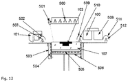
- FIG. 12 is a drawing showing of an illustrative construction including an emitter attached to a print head axle.
- FIG. 13 is a drawing showing an illustrative construction including an overhead lame having emitters of different wavelengths.
- an object underlying the application is achieved by specifically combining advantageous building components and process parameters which result in advantageous process results.
- the powder can be processed in the machine at a lower temperature or with a lower temperature input or energy input, and powder aging due to thermal damage can be reduced substantially.
- powder aging due to thermal damage can be reduced substantially.
- a small volume around the component has to be discarded due to the considerable thermal effect.
- a “3D moulded part”, “moulded article” or “component” in the sense of the invention are all three-dimensional objects manufactured by means of the method according to the invention and/or the device according to the invention which exhibit dimensional stability.
- Construction space is the geometric location where the particulate material bed grows during the construction process by repeated coating with particulate material or through which the bed passes when applying continuous principles.
- the construction space is generally bounded by a bottom, i.e. the construction platform, by walls and an open top surface, i.e. the construction plane. In continuous principles, there usually is a conveyor belt and limiting side walls.
- the construction space can also be designed in the form of what is called a job box, which constitutes a unit that can be moved in and out of the device and allows batch production, with one job box being moved out after completion of a process to allow a new job box to be moved into the device immediately, thereby increasing both the production volume and, consequently, the performance of the device.
- the “heating phase” refers to heating of the device at the beginning of the process.
- the heating phase is complete as soon as the actual temperature of the device reaches a stationary value.
- the “cooling phase” refers to the time required to cool the particulate material to such an extent that the parts contained therein are not subject to any significant plastic deformation when removing them from the construction space.
- the “particulate materials” or “particulate construction materials” or “construction materials” of use herein may be any materials known for powder-based 3D printing, in particular polymers, ceramics and metals.
- the particulate material is preferably a free-flowing powder when dry, but may also be a cohesive, cut-resistant powder or a particle-charged liquid. In this specification, particulate material and powder will be used synonymously.
- the “particulate material application” is the process of generating a defined layer of powder. This may be done either on the construction platform or on an inclined plane relative to a conveyor belt in continuous principles.
- the particulate material application will also be referred to below as “coating” or “recoating”.
- “Selective liquid application” in the sense of the invention may be effected after each particulate material application or irregularly, depending on the requirements for the moulded article and for optimisation of the moulded article production, e.g. several times with respect to particulate material application. In this case, a sectional image of the desired article is printed.
- the “device” used for carrying out the method according to the invention may be any known 3D-printing device which includes the required parts. Common components include coater, construction field, means for moving the construction field or other components in continuous processes, metering devices and heating and irradiating means and other components which are known to the person skilled in the art and will therefore not be described in detail herein.
- the “absorber” in the sense of this invention is a medium which can be processed by an inkjet print head or any other device working in a matrix-like manner, which medium enhances the absorption of radiation for local heating of the construction material.
- the absorber may also be in the form of particles, e.g. black toner.
- Absorbers may be applied uniformly or selectively, in different amounts.
- the absorber may be applied as a mixture of absorbers with different absorption maxima, or different absorbers may be applied independently, e.g. one after another, in an alternating manner or in a predetermined sequence.
- applying different amounts allows the strength in the construction material to be controlled and to selectively achieve different strengths, e.g. in the moulded part to be produced and the jacket surrounding it.
- the strength ranges from a strength as in the component itself to a strength that is only insignificantly above that of the construction material without the absorber printed thereon. This allows temperature control in the construction field/construction space and also allows easy removal, if desired, of the jacket surrounding the produced component, which jacket serves the purpose of temperature control.
- Absorption refers to the uptake by the construction material of thermal energy from radiation. The absorption depends on the type of powder and the wavelength of the radiation.
- the “support” refers to the medium in which the actual absorber is present. This may be oil, a solvent or generally a liquid.
- Random-induced heating as used hereinafter means irradiation of the construction field by stationary or mobile sources of radiation.
- the absorber is adapted to the type of radiation and preferably optimised. This is intended to produce differences in heating between “activated” and “non-activated” powder. “Activated” means that, by the absorber printed therein, the temperature in these regions is increased as compared to the other regions in the construction space.
- Base temperature in the sense of the invention means the temperature which is adjusted in the construction space on the surface of the particulate material and in the printed particulate material by suitable means, e.g. an IR emitter.
- the basic temperature is selected so as to be suitable, with respect to the particulate material and in interaction with the absorber, to achieve selective solidification with positive material properties.
- IR heating as used herein specifically means irradiation of the construction field by an IR emitter.
- the emitter may be either static or movable over the construction field by a displacement unit. Using the absorber, the IR heating results in different temperature increases in the construction field.
- An “IR emitter” is a source of infrared radiation. Usually, incandescent filaments in quartz or ceramic housings are used to generate the radiation. Depending on the materials used, different wavelengths result for the radiation. In addition, the wavelength of this type of emitter also depends on the power output.
- An “overhead lamp” in the sense of the invention is a source of radiation mounted above the construction field. It is stationary, but has an adjustable radiant flux.
- the “sintering lamp” is a source of radiation which heats the process powder (particulate construction material) to above its sintering temperature. It may be stationary. In preferred embodiments, however, it is moved over the construction field.
- “Sintering” or “melting” is the term for the partial coalescence of the particles in the powder. In this system, the build-up of strength is connected with the sintering.
- sining window refers to the difference in temperature between the melting point occurring when first heating the powder and the solidification point during the subsequent cooling.
- the “sintering temperature” is the temperature at which the powder first begins to fuse and bond.
- Recycling rate refers to the ratio of the amount of particulate material that can be used for a new process cycle after completion of the construction process to the total amount of particulate material required for one process cycle. Particulate materials whose properties change due to the construction process, sometimes require the admixture of an amount of particulate material not used in the process.
- a typical example is polyamide 12 , which is subject to irreversible thermal damage upon heating close to the melting point.
- the “packing density” describes the filling of the geometric space by solid matter. It depends on the nature of the particulate material and the application device and is an important initial parameter for the sintering process.
- shrinkage refers to the process of geometric shortening of a dimension of a geometric body as a result of a physical process.
- the sintering of suboptimally packed powders is a process resulting in shrinkage with respect to the initial volume. Shrinkage can have a direction assigned to it.
- Deformation occurs if the body is subject to uneven shrinkage in a physical process. Such deformation may be either reversible or irreversible. Deformation is often related to the global geometry of the component.
- “Curling” as used herein refers to an effect resulting from the layer-wise approach of the described invention. This means that layers generated in quick succession are subject to different degrees of shrinkage. Due to physical effects, the compound then deforms in a direction which does not coincide with the direction of shrinkage.
- greyscale value refers to the amount of absorber printed into the powder. According to the invention, different greyscale values can be printed onto the construction field in order to achieve different degrees of heating.
- the construction material is always applied in a “defined layer” or “layer thickness”, which is individually adjusted according to the construction material and the process conditions. It is, for example, 0.05 to 0.5 mm, preferably 0.1 to 0.3 mm.
- Temperature difference refers to the difference in temperature in the construction field in areas which are or are not printed with absorber and, consequently, are intended to solidify or not. Another aim may be for some regions to solidify only partially or only to a very small extent and even, essentially, to not solidify at all, despite the absorber printed in, as is the case with preferred embodiments of the jacket. The temperature differential will vary accordingly.
- Tempoture band refers to the temperature range within which regions of the particulate material are heated and then cooled again during the layer construction process.
- Temporal control refers to the adjustment of a desired temperature in the construction space, which may be kept constant or may be varied cyclically. Preferably, a basic temperature is set to a selected value.
- “Jacket” in the sense of the invention is a region or layer which surrounds the moulded part and which, during the layer construction process, is heated up more than the powder disposed outside which is neither part of the jacket nor of the moulded part.
- the jacket allows the specific local control of the temperature in the process, especially in the desired moulded part.
- the jacket is characterised by having absorber printed in at least some parts thereof. Preferably, absorber is printed into the jacket in each layer or in regularly recurring layers. This jacket may be several millimetres thick and surrounds the moulded part to be manufactured over its entire circumference and as a whole.
- the jacket may consist of recurring rings (from the bottom to the top, in the direction of construction), which surround the moulded part and are characterised by having absorber printed into them.
- the jacket may have a strength which corresponds to that of the moulded part, but is preferably lower than that of the moulded part.
- the jacket only has a slightly higher strength than the construction material itself and thus has the advantage of being easily removable from the moulded part after the construction process.
- the invention relates to a method of producing 3D moulded parts, wherein particulate construction material is applied onto a construction field in a defined layer by means of a coater, one or more liquids or particulate material of one or more absorbers is/are selectively applied, this layer is heated in a first heating step to a basic temperature of the powder without the absorber, which is within the sintering window of the, e.g., polyamide powder, and heat input in a second sintering step leads to selective solidification of the areas printed with absorber, at a sintering temperature above the melting temperature of the powder, wherein the areas with the selectively applied absorber heat up more in the first step than the areas without absorber, and thus a temperature difference is set between areas with and without absorber, the construction field is lowered by one layer thickness, or the coater is raised by one layer thickness, these steps are repeated until the desired 3D moulded part is produced, wherein the heating step to said basic temperature is effected by an emitter with
- the wavelength is to be selected as describe above, said wavelength being the peak wavelength of blackbody radiation.
- an absorber which is suited to the other process conditions, said absorber preferably being a liquid, which is preferably an oil-based ink containing carbon particles.
- a suitable ink is XAAR IK821.
- the method according to the invention preferably uses a particulate construction material which has an average particle size of 50-60 ⁇ m, preferably 55 ⁇ m, a melting temperature of 180-190° C., preferably 186° C., and/or a recrystallization temperature of 140-150° C., preferably 145° C.
- a particulate construction material which has an average particle size of 50-60 ⁇ m, preferably 55 ⁇ m, a melting temperature of 180-190° C., preferably 186° C., and/or a recrystallization temperature of 140-150° C., preferably 145° C.
- Such construction materials include polyamide 12 , PA2200® or VESTOSINT 1115®.
- the coating cycle is selected to match the other process parameters, and one complete coating cycle takes 20 to 40 s.
- a “complete coating cycle” is understood to be the operation during which the coater and the printing unit respectively move over the entire surface of the construction field.
- the basic temperature is advantageously set to 145° C. to 186° C., preferably 160° C. to 180° C., and/or the sintering temperature is set to 175° C. to 220° C., preferably 190° C. to 210° C.
- the temperature or heat input is achieved via an emitter or a thermolamp, preferably a glass or ceramic lamp, and the distance from the emitter to the construction field surface is preferably 10 to 50 cm, preferably 15 to 30 cm, more preferably 15 to 25 cm.
- the invention relates to a method of producing 3D moulded parts, wherein particulate construction material is applied onto a construction field in a defined layer by means of a coater, one or more liquids or particulate material of one or more absorbers is/are selectively applied, this layer is heated, wherein the areas with the selectively applied absorber heat up more than the areas without absorber, and thus a temperature difference is set between areas with and without absorber, the construction field is lowered by one layer thickness, or the coater is raised by one layer thickness, these steps are repeated until the desired 3D moulded part is produced, and absorber is additionally printed around the 3D moulded part in order to produce at least one jacket.
- An embodiment is particularly preferred wherein heating takes place such that only the areas printed with absorber connect by partial melting or sintering.
- the recycling rate of the construction material and, thus, cost-effectiveness is increased. It also becomes possible to better adjust the temperature in the construction space and the individual regions of the construction material and to mitigate or fully eliminate problems such as curling.
- the construction material may be present in any suitable form and with agents that can be applied by the device.
- the device used for the method may be adapted to the construction materials by suitable means and also constructionally, by known means.
- the construction material is preferably used in the form of a powder or dispersion.
- the temperature in the construction space is set to a temperature which is advantageous for the method and is adapted to the construction material; this temperature may also be referred to as the basic temperature.
- the newly applied layer is preferably heated by radiation in a planar or sweeping manner such that it quickly reaches the basic temperature.
- the construction material on the construction field or in the job box, respectively may also be temperature-controlled.
- absorbers known from HSS processes may be used, preferably using different absorbers in the 3D moulded part and in the jacket, or preferably using the same absorber in both.
- the absorber may be applied to all selective regions either in the same amount or in different amounts. Preferably, less absorber is applied in the jacket area. Further, the application of absorber in the jacket area may be selected so as to adjust the strength of the jacket, on the one hand, and influence the temperature by the introduction of absorber into the jacket and by selection of the jacket thickness, on the other hand. Preferably, the same absorber or a different absorber is used for the jacket as for the moulded part.
- the absorber is selected and dosed according to the desired properties and effects in the method.
- the absorber used for the jacket prevents sintering of the construction material.
- the selectively printed liquid may be the absorber itself or may contain or comprise the absorber as well as additional substances.
- the absorber preferably comprises radiation-absorbing components, plasticizers for the particulate construction material. If polyamide or a similar material is used as the particulate material, the absorber may additionally include one or more substances interfering with recrystallization.
- one source of radiation is used for each absorber, preferably using two absorbers with two sources of radiation.
- any suitable means may be used as the source of radiation or heat, said sources of radiation preferably emitting infrared radiation in the wavelength range from 1 to 20 ⁇ m.
- the jacket is constructed with a wall thickness of 1 to 10 mm, preferably 2 to 5 mm and more preferably 3 mm.
- the process may cause the jacket to solidify or not. Preferably, the process does not cause the jacket to solidify.
- An important aspect of the invention is the temperature control in the process, in particular in the areas where absorber is applied and in the areas having no absorber applied thereon.
- the temperatures, temperature differences, and cyclisation of the temperature are adapted to each construction material and to the absorber used, so as to obtain the desired moulded parts and achieve the advantageous effects of the method according to the invention.
- the same temperature or locally different temperatures are set or generated in the applied construction material.
- a temperature is set in the jacket that is below the sintering temperature of the construction material in this area. It is also possible to adjust or achieve a specific temperature profile, by forming and placing the jacket accordingly.
- a temperature profile is generated, in the applied construction material, that is characterised by a temperature distribution of low: higher: still higher (T 1 ⁇ T 2 ⁇ T 3 ) in the following areas: area outside the jacket: jacket area: area within the jacket (jacket ⁇ jacket area ⁇ area within the jacket) according to FIG. 6 .
- the temperature achieved in the construction field is controlled directly by the energy input, with the jacket influencing the local temperature adjustment.
- heat or energy input may be performed in a uniform or locally differing manner across the construction field.
- the temperature adjustment can be controlled by the construction of the jacket and is controllable by the introduction of the absorber.
- an absorber is used for the jacket which has a higher boiling point than the absorber used for the 3D moulded part.
- the amount of the absorber or absorbers is preferably controlled via greyscale values of the print head or via dithering methods.
- Known print heads with suitable technology are used to apply the liquid and the absorber.
- the liquid may be selectively applied by means of one or more print heads.
- the print head or print heads are adjustable in terms of drop mass.
- the print head or print heads may selectively apply the liquid in one or both directions of movement.
- the method achieves that the particulate construction material is selectively solidified, preferably selectively solidified and sintered.
- the construction material and the absorber are cyclically applied.
- the construction field is lowered by the desired layer thickness or the application units are raised correspondingly. These operations are cyclically repeated.
- the basic temperature in the construction material is also adjusted, and then the temperature is cyclically increased within a temperature band above the basic temperature in selected areas and decreased again.
- the temperature band is determined by the material. Depending on the selection of the construction material, the temperature band preferably extends within a range from 0 to ⁇ 50 K, 0 to ⁇ 30 K, 0 to ⁇ 20 K and 0 to 10 K, from the melting point of the construction material.
- the different areas on the construction field are adjusted to corresponding temperatures.
- the temperature difference between areas with and without absorber is within a range of from 0.5 to 30 K.
- that temperature range is of importance which is adjusted in the area printed with absorber and in the other areas.
- the temperature in the area printed with absorber or in the area within the jacket is set within a temperature range from 0 to ⁇ 30 K, preferably 0 to ⁇ 25 K, more preferably 0 to ⁇ 15 K, with respect to the melting point of the construction material.
- the absorber and the temperature are selected such that the jacket can be easily removed by powder blasting or by means of an air jet after the construction process.
- the moulded part preferably has a jacket surrounding it substantially along its entire circumference, said jacket having been constructed using an absorber and there being unsolidified particulate construction material between the 3D moulded part and the jacket. Different strengths may be adjusted in the moulded part.
- the jacket preferably has a strength which is lower, substantially the same as or higher than that of the component.
- the 3D moulded part is manufactured using an absorber, said 3D moulded part being surrounded, substantially along its entire circumference, by a jacket, said jacket having been constructed using an absorber, and said jacket being easily removable after the construction process by powder blasting or an air jet.
- the jacket may be built laterally around the 3D moulded part and upwards during the construction process. This happens simultaneously with the construction of the 3D moulded part.
- the device is temperature-controllable and preferably comprises an insulation ( 506 ) on the construction platform ( 102 ) downwardly and/or preferably laterally.
- the device may comprise a resistance heating ( 504 ).
- the construction platform ( 102 ) may be arranged directly in the device or may be part of a job box or of a construction container.
- the device is preferably characterised by a construction platform ( 102 ) in a construction container ( 110 ), said construction container ( 110 ) preferably being temperature-controllable.
- thermolamps irradiation devices etc.
- the device preferably comprises a heating means disposed above the construction platform, preferably an overhead lamp ( 108 ).
- the device comprises a mobile heating means, preferably a sintering lamp ( 109 ).
- the sintering operation or the bonding of the particulate material, which has been selectively printed with absorber is even further improved in that the temperature control or the energy input, respectively, occurs in a differentiated manner, allowing to obtain a component with improved properties.
- the disclosure relates to a 3D printing method as well as a device suitable for said method, which is preferably carried out as an HSS process and is characterised in that two sintering lamps with different wavelength spectra or energy inputs are used, preferably two sintering lamps or one sintering lamp whose spectrum is characterised by being composed of two different blackbody radiation spectra, or is characterised by having a spectrum which differs from the blackbody radiation spectrum.
- a device and a method are disclosed, wherein the temperature adjustment of the particulate material and of the regions which are to solidify in the particulate material is effected by at least two emitters (sintering lamps) or one emitter with different wavelengths and/or energy input.
- At least two sintering lamps covering a different radiation spectrum are used for this purpose in the device. This allows a further differentiated adjustment of the process conditions.
- An advantageous result thereof is that a temperature is reached for the unprinted and absorber-free powder that is not too high and thus substantially prevents undesired adhesion of said material, while on the other hand allowing to achieve an optimised melting temperature in the region of the particulate material which contains absorber.
- each sintering lamp is preferably controllable independently of each other and can be moved independently over the construction field.
- a wavelength spectrum or wavelength, respectively, adapted to the respective particulate material and the binder to be imprinted is selected and adapted to the other process parameters, such as traversing speed, basic temperature, and particle layer thickness.
- each sintering lamp may be used with a pre-selected level, such as, e.g., 50, 60, 70, 80, or 90% of its maximum power.
- a typical traversing speed of the sintering lamps is in the range of 90 to 150 mm/s, preferably 100 to 120 mm/s.
- the at least two, preferably two, sintering lamps are preferably coupled with the coater or arranged independently thereof on their own axles.
- the two sintering lamps have different wavelengths and are moved across the construction field substantially simultaneously, preferably in an alternating manner or one after the other.
- the powder bed with the particulate material applied thereon is heated or its temperature is thereby adjusted as are the areas printed with absorber.
- more radiation is absorbed in the areas printed with absorber, allowing a more optimal adjustment of the melting temperature in the areas to be solidified, which has a positive effect on the component's properties, in particular in terms of strength.
- the temperature substantially remains below the melting temperature, thereby avoiding a solidification which would make unpacking more difficult. Partial melting is thus substantially avoided.
- two infrared halogen emitters are preferably used, which differ slightly in their generated wavelengths, though.
- the second emitter is simply arranged behind the first emitter. There is no need for both emitters to be simultaneously activated every time, but they may also alternate, e.g. emitter 1 when traversing from left to right, then emitter 2 from right to left, etc.
- thermolamp may be structured in such a manner that it includes both the emitters for adjustment of the basic temperature in the construction space and the emitters required for the solidification process, wherein the latter may again cover at least two different wavelengths or wavelength ranges.
- the recoater axle (coater) includes a second radiation emitter ( 509 ) with a reflector ( 510 ) to the right of the first emitter ( 507 ).
- the second emitter is characterised in that its radiation spectrum differs from that of the first emitter. This may be achieved, for example, in that an emitter with a power of 1 kW and a length of 350 mm has a near-infrared spectrum with a peak wavelength of 1 ⁇ m, while the second emitter with a power of 1 kW and a length of 350 mm has a medium-wavelength spectrum with a peak wavelength of 2 ⁇ m.
- the traversing speed of the recoater axle can also be adjusted in addition so as to regulate the energy input.
- a combination of two emitters having a short wavelength spectrum, a peak wavelength of 1.2 ⁇ m and a medium wavelength spectrum of 2 ⁇ m is possible, wherein one respective emitter is preferably deactivated, depending on the direction in which the recoater axle passes over the powder bed.
- the sintering pass is carried out with both emitters activated, while the return movement with application of the next layer of particulate material is carried out with the short wavelength emitter deactivated.
- a higher energy efficiency as well as a higher sintering pass speed are thus achievable in an advantageous manner.
- the axle systems are constructed in a design that is as narrow as possible so as to keep shading effects of the powder surface by the overhead heating elements (thermolamp) to a minimum. This also prevents or at least reduces cooling.
- both emitter types can be accommodated within one single quartz glass bulb [ FIG. 11 ]. Mounting laterally of the coater unit is also possible so as to be able to compensate for shading effects [ FIG. 10 ].
- the use of emitters of different spectra in the overhead heating element ( 500 ) enables reduced power levels of the emitters on the coater or print head unit, respectively, and thus offers the advantage of reduced heat development on the respective units, which consequently have to be cooled to a reduced extent.
- Another preferred embodiment may consist in that one, preferably two emitters with different radiation spectra are additionally attached to the print head axle [ FIG. 12 ].
- This has the advantage that, when the powder surface is sufficiently shielded, e.g. by a metal roller cover spanning the powder bed, the overhead heating system can be dispensed with completely. Not only does this allow the power consumption of this assembly to be reduced, but the pass of both axle systems also allows the powder surface to be adjusted to a more uniform temperature, which benefits the strength and dimensional stability of the components produced by the method.
- emitters of different wavelengths may also be attached to the overhead heating system [ FIG. 13 ].
- emitters on the axle systems can be dispensed with altogether, so that their traversing speed can be maximised due to the now lower mass and smaller dimensions.
- this advantageously shortens the shading of the powder surface by the overhead heating elements, which prevents cooling of the surface.
- the construction in this preferred embodiment is characterised in that ceramic heating elements are used on the overhead heating system in order to produce the basic temperature of the powder surface, while after selective printing/wetting of the powder surface with absorber by the print head, near infrared emitters in the overhead heating system are, however, activated in addition for a defined time of preferably 8s and homogeneously illuminate the powder surface. This then results in melting of the particulate material of the wetted surface.
- the disclosure relates to a device suitable for carrying out a method as described above.
- a device is preferred which is characterised by comprising the following features: a heating element ( 507 ) which is arranged on the oscillating blade recoater ( 101 ) and has a peak wavelength 0.3 ⁇ m to 3 ⁇ m, preferably 0.7 ⁇ m to 2.5 ⁇ m, particularly preferably 0.9 ⁇ m to 1.4 ⁇ m; preferably a reflector ( 502 ); a further heating element ( 509 ), preferably with a reflector ( 510 ), which preferably has a radiation spectrum differing from that of heating element ( 507 ), of 1 ⁇ m to 3 ⁇ m, preferably 1.5 ⁇ m to 2.5 ⁇ m, particularly preferably 1.7 ⁇ m to 2.2 ⁇ m, and/or is operated simultaneously with the heating element ( 507 ) at a different power of 200 W to 2 kW, preferably 350 W to
- Another preferred embodiment is a device comprising a further heating element ( 514 ) with a spectrum differing from the first heating element ( 513 ), said further heating element ( 514 ) being arranged on the overhead lamp ( 108 ) with a peak wavelength of 0.3 ⁇ m to 3 ⁇ m, preferably 0.7 ⁇ m to 2.5 ⁇ m, particularly preferably 0.9 ⁇ m to 1.4 ⁇ m.
- the advantage of using two emitters with different radiation spectra resides in controlling the temperature of the unwetted surface of the coating ( 107 ) independently of the temperature of the wetted powder surface ( 103 ) (areas selectively printed with absorber).
- the inventive idea is evident, among others, from FIG. 9 in a preferred embodiment.
- Emitter 1 with medium wavelength spectrum (peak wavelength 1.6 ⁇ m), emitter 2 with near-infrared spectrum (peak wavelength 0.98 ⁇ m).
- Emitter 1 with medium wavelength spectrum (peak wavelength 1.6 ⁇ m), emitter 2 with short wavelength spectrum (peak wavelength 1.2 ⁇ m).
- Emitter 1 with medium wavelength spectrum (peak wavelength 1.6 ⁇ m), emitter 2 with long wavelength spectrum (peak wavelength 4.6 ⁇ m).
- Emitter 1 with long wavelength spectrum (peak wavelength 4.6 ⁇ m), emitter 2 with near-infrared spectrum (peak wavelength 0.98 ⁇ m).
- Emitter 1 with long wavelength spectrum peak wavelength 4.6 ⁇ m
- emitter 2 with short wavelength spectrum peak wavelength 1.2 ⁇ m
- Emitter 1 with short wavelength spectrum (peak wavelength 1.2 ⁇ m), emitter 2 with near-infrared spectrum (peak wavelength 0.98 ⁇ m).
- one emitter is a ceramic emitter or a quartz emitter
- the disclosed method may be varied by variations in the time sequence of individual process steps, thereby achieving advantageous process results:
- Both emitters are activated during the pass over the powder surface ( 103 )
- the object underlying the application may also be attained in that the temperature fine adjustment or temperature optimisation, respectively, is achieved by using printing fluids with an advantageous absorption spectrum, so that particulate material wetted with them can be heated to an optimised degree, if possible, by means of a defined infrared emitter spectrum.
- Different printing fluids adssorbers
- the printing fluid is advantageously adapted to the emitters and, in this case, the method can be carried out using an overhead emitter and a sintering emitter.
- One, two, or three different printing fluids may be applied simultaneously, successively, in an alternating manner, selectively as a mixture.
- the printing fluid or the printing fluid mixture may have an absorption maximum, for example, between 750 and 900 nm, preferably from 780 to 850 nm, more preferably 815 nm.
- Each printing fluid may have a different one of the above-mentioned absorption maxima.
- one object i.e. preventing or effectively reducing powder aging, is preferably achieved by imprinting absorbers outside the geometric area of the actual component. This measure allows the amount of powder subject to high temperatures to be reduced.
- the aging of the powder is a chemical process which, according to the literature, includes different mechanisms.
- the following subprocesses can be found for polyamide 12 : Firstly, the oxygen in the air has an oxidative effect and modifies the base material. Reactive groups are bound thereby and strength cannot fully develop. Secondly, the chains of the base polymer grow. This increases the melting viscosity and processing cannot be performed in the same manner as with a new powder. A third effect is considered to be a certain reduction in reactive terminal groups. This occurs as a result of the mutual reaction of polymer chains with one another. It is particularly important for interlaminar bonding.
- the prior art method consists of the steps of layering, printing, exposure to radiation and lowering.
- the first step is analogous to the layering in known powder-based 3D printing. Powder is placed in front of a blade, applied onto a construction platform and smoothened by the blade. In this case, the layer thickness determines the positions of the construction platform in two successive coating operations.
- liquids are applied by an inkjet print head.
- the absorber which causes local heating of the powder upon exposure to radiation.
- the absorber may also be a powder, preferably a carbon toner, which is selectively applied in a suitable manner.
- the layer thus printed is then scanned by a radiation source and thereby selectively heated.
- the entire powder is heated by the source of radiation.
- the temperature increases particularly in activated areas such that the particles begin to sinter and thereby bond.
- the construction field is lowered by one layer thickness. Then, all the above-mentioned steps are repeated until the desired component is obtained.
- an additional, stationary source of radiation is preferably present above the construction field.
- the additional source of radiation acts whenever the construction field is not covered by a unit, such as the coater or the print head.
- This overhead lamp as it is called, is preferably controlled so as to set a constant temperature on the construction field.
- a pyrometer sensor may be used to determine the actual temperature.
- the overhead lamp constitutes the central temperature control component.
- the construction field is maintained at a temperature near the sintering temperature.
- the additional energy for sintering the powder is then low and can be introduced by gently acting means.
- the temperature surrounding the component is so high that the temperature does not drop below the recrystallization temperature, even in the peripheral areas of the component, as the construction process progresses and, consequently, does not disrupt layering.
- this effect may also be produced by imprinting absorber outside the component. This generates an area which, on the one hand, is heated to near the sintering temperature and, on the other hand, is controlled to have a temperature low enough to prevent the powder from sintering in this area.
- the entire powder is heated to a temperature near the sintering temperature.
- the energy exchange with the unprinted area is driven by the temperature difference of few degrees Celsius.
- cooling takes place at a time when many layers have already been built on top of each other in the powder bed.
- the method according to the invention can be carried out with the same kind of sintering at a much lower temperature.
- the parameters are the relative amount of absorber and the width of the “jacket” around the component. Temperature control is effected by the controlled overhead lamp.
- the input amount can be adjusted via the printing resolution.
- the latter may be adjusted, e.g. by multiple passes, if only one absorber and one print head are used.
- the cross-section of the component is printed in a first step.
- the jacket can be printed with an adapted resolution. This method requires two passes and is therefore suboptimal in terms of process speed.
- a particularly simple method consists in weakening the printed images in the area of the jacket by what is called dithering.
- various mathematical algorithms may be used to distribute the printed dots such that the thermal effect in the jacket achieves the desired level.
- a technically more complex method is the use of greyscale inkjet print heads. It allows a selectable adjustment of the drop mass during printing.
- the second print head can be moved along with the first one.
- the use of the second liquid medium allows particularly precise adjustment of the effect. This applies, on the one hand, to the thermal effect.
- the required amount of heat input can be influenced by the relative amount of absorber. This may have technical advantages with respect to resolution and relative drop mass.
- a separating agent may be introduced which considerably delays sintering. This avoids adhesion to the component and, consequently, facilitates unpacking of the components.
- This effect can be enhanced even to the extent that the temperature of the jacket is above that of the component. As a result, additional sintering can be achieved in the peripheral area of the actual component. Deformation by cooling can thus be prevented even better.
- the device required in order to carry out the invention is closely modelled on a 3D printer for powder-based printing.
- further process units are used for temperature control and imprinting of the process liquids.
- the entire device is heated up.
- all heating elements are used to increase the temperature.
- the heating phase is complete as soon as the temperature remains constant in all measurement locations of the system.
- the construction platform ( 102 ), on which the powder is deposited in the process and by which the layer thickness of the layers ( 107 ) is adjusted, can be heated by various systems.
- a preferred embodiment uses an electric resistance heating ( 504 ).
- the latter is provided as a planar heating film, based on considerations of a homogeneous heating effect. The effect of this heating is registered and controlled by a sensor.
- the sensor is connected directly with the construction platform.
- the construction platform itself is made of metal, preferably aluminium.
- An insulation ( 506 ) covers the construction platform ( 102 ) downwardly.
- the construction platform may also be heated by a fluid.
- heating coils ( 504 ) are installed below the preferably metallic construction platform.
- an insulation ( 506 ) is disposed in order to homogenise the heating effect.
- a heat transfer oil flows through the heating coils. Preselecting the oil temperature allows exact temperature adjustment. Very precise temperature control can be achieved by ensuring a sufficiently high flow rate and adjusting the power.
- the construction platform ( 102 ) is moved in the construction container ( 110 ) as it is called.
- the container may be designed to be removable from the 3D printing device. In this manner, a great temporal machine efficiency can be achieved, as a second construction container can be used in the device while unpacking the components.
- the construction container ( 110 ) is also heated.
- the container itself is preferably made of metal again, preferably of aluminium to ensure good heat conduction.
- the actual active heating ( 504 ) is in turn backed by an insulation ( 503 ). This allows the effect to be enhanced, while increasing homogeneity.
- a plug-in system is preferably arranged between the device and the construction container for power connection. This may include an electrical connection or a connector for liquids.
- the next essential heating system of a device according to the invention is the overhead lamp ( 108 ).
- the overhead lamp ( 108 ) is preferably disposed above the construction field and irradiates the construction field perpendicularly. Also preferred are laterally mounted emitters which irradiate the construction field at a certain angle. Such a construction is preferred in order to minimise the shading effect of the coater or the print head.
- the overhead lamp ( 108 ) is preferably equipped with infrared emitters ( 500 ).
- the latter may be quartz glass lamps or ceramic emitters. The selection depends on the absorber selected and the combination which is best, considering the nature of the process, and fits the wavelength.
- the method to operate the overhead lamp ( 108 ) in a controlled manner.
- a pyrometer ( 501 ) as the sensor may be preferred.
- the pyrometer is directed towards an peripheral area of the construction field, which the control system ensures is not a region printed with absorber.
- the actual sintering is carried out by an infrared lamp ( 109 ) carried along with the coater. Said lamp heats the construction field as it passes over the latter.
- the lamp may be used to heat the freshly printed powder or an already covered powder layer. Due to the necessary temperature dynamics, a quartz emitter is preferably used here.
- the powder is preheated before application onto the already existing powder surface so as to prevent excessive cooling of the layer.
- An electric resistance heating in the coater is also suitable to preheat the powder.
- all units can also be heated indirectly via infrared radiation.
- the coater is heated by radiation if strong vibrations occur.
- a powder layer is formed by the coater ( 101 ) on the construction platform ( FIG. 1 , part a)).
- the new layer can be additionally heated by the sintering lamp ( 109 ).
- this layer is printed on by one (100) or several inkjet print heads ( 100 and 508 ) ( FIG. 1 , part b)).
- the construction platform ( 102 ) is lowered (part d). Now, the printed layer is heated by the sintering lamp ( 109 ) and then covered with powder again.
- This operation is repeated until completion of the components ( 103 ) in the construction container ( 110 ). Then the cooling phase follows. This phase preferably takes place in the construction container which is then supplied with energy outside the device.
- FIG. 2 presents temperature diagrams.
- FIG. 2 part a) schematically shows the profile of the energy emitted by the powder when it is heated and cooled again in one cycle.
- sintering temperature the material melts or sinters (sintering temperature).
- sintering temperature the material melts or sinters
- recrystallization temperature This is where the molten material solidifies.
- FIG. 2 , parts b) and c) show the temperature profile during a process run according to a prior art method.
- FIG. 2 , part b) shows the temperature profile on the unprinted surface. Using the sintering radiation source produces heating and cooling phases in the otherwise constant profile. In the unprinted area, the temperature never reaches the sintering temperature.
- FIG. 2 , part c) shows the profile in the printed area.
- the process is controlled at least such that the sintering temperature is briefly exceeded, so that part of the powder is melted and remains molten. Excessive heating may cause all of the powder to melt in this area, resulting in massive warping. Excessive cooling of the printed area must also be avoided, because otherwise recrystallization will start, and then all shrinkage due to the now possible power transmission will lead to geometric warping (curling), which may make the further process impossible.
- FIG. 8 describes an advantageous combination of assembly parts by which the advantageous process conditions according to the invention can be achieved. Further details thereof are illustrated in embodiment example 4.
- FIGS. show the aspect of at least two sintering lamps or of at least two emitter types in one sintering lamp or thermolamp.
- FIG. 9 shows a construction, wherein in addition to the heating element ( 507 ) with reflector ( 502 ) another heating element ( 509 ) with reflector ( 510 ) having a different radiation spectrum is used.
- FIG. 10 shows a second variant of the construction, wherein the second heating element is arranged on the left, next to the oscillating blade.
- FIG. 11 shows a construction, wherein both heating elements having different spectra are mounted together, preferably inside a quartz glass bulb.
- FIG. 12 shows a construction wherein further heating elements, optionally having different peak wavelengths, are mounted on the print head axle system.
- FIG. 13 shows a construction, wherein the overhead-heating unit comprises an additional type of emitter whose emitted spectrum differs from that of the first one.
- the injket print heads common in 3D printing deposit one droplet on a dot in the raster of the print area. The size of said droplet is adjusted once.
- a respective cross-sectional image of the desired components ( 103 ) is printed using absorber, said image being adapted to the construction height.
- the image is printed in an intensity ensuring definite sintering of the particles during the pass of the sintering lamp.
- unprinted areas will remain unsintered.
- the necessary amount of liquid imprinted per raster dot in this case will be considered black in the following.
- a jacket ( 301 ) is printed around the component, said jacket ( 301 ) representing a greyscale value, i.e. containing less absorber based on the local average.
- the jacket ( 301 ) is determined from the raw data during layer calculation. In this case, e.g. for the .stl file format, the jacket area is generated by an offset of the triangular areas.
- the greyscale value can be achieved in the raster area by mathematical methods.
- the coverage of the jacket area with printed dots is controlled such that the desired greyscale value is achieved on average in a certain local viewing area.
- An example of such a mathematical method is the so-called error diffusion method.
- an area is used for averaging, and the corresponding raster dots are placed as a function of the greyscale value.
- 30 dots must be printed “black” and 70 dots remain unprinted.
- a conventional print head ( 100 ) will suffice.
- the device does not differ from the prior art devices. Also, the same data paths can be achieved, because the information can be stored in one single monochromatic raster bitmap.
- FIG. 7 , part a) shows the temperature in the unprinted area. It may even be considerably below the recrystallization temperature because the peripheral area ( 301 ) is not raised above the sintering temperature and, thus, does not enable any power transmission.
- the curve in FIG. 7 , part b) shows the temperature in the peripheral area ( 301 ) of the component.
- the temperature should be above the recrystallization temperature and below the sintering temperature so that the heat transfer cannot cause the component area to drop below the recrystallization temperature and said area can be easily removed after the construction process.
- a device comprising a greyscale print head is more precise in use.
- These print heads are common and well-known in the print media sector. They allow the apparent resolution to be increased in this sector, thus achieving a better image quality.
- this technique can be used to introduce different amounts of liquid in the component ( 103 ) and jacket ( 301 ) areas.
- the amount of liquid introduced in the jacket area may be set to 50% of that introduced in the component area.
- Data transmission is effected by the use of a polychromatic raster bitmap. As a minimum, another raster bitmap can be defined which contains the data for the peripheral area. The electronic system of the print head then considers the respective bits as greyscale information.
- a second print head ( 508 ) is used which can print the second absorber.
- the data path in the control unit of the machine need not be changed.
- the data is divided up electronically before the respective print head.
- This print head need not be a separate physical unit, but can be part of the print head ( 100 ) of the device.
- the second absorber liquid may contain an oil, for example, which serves as a separating agent. This separating agent deposits between the individual particles and prevents their contact with the molten base material.
- an oil for example, which serves as a separating agent. This separating agent deposits between the individual particles and prevents their contact with the molten base material.
- a certain amount of silicone oil in the printing liquid may serve as separating agent. This oil must be maintained as a suspension with the rest of the ink which additionally includes the absorber.
- composition is:
- the oil Since the oil has a high boiling point, it does not evaporate during the sintering operation. In the jacket area ( 301 ), no sintering of the particles is possible. However, the oil produces an peripheral layer which adheres to the component and is easy to remove when unpacking the components. It can be removed separately from the rest of the powder. This avoids major contamination of the powder during further cycles.
- This liquid is imprinted in the peripheral area ( 301 ) in the same amount as the liquid in the component area ( 103 ).
- the liquid in the component area ( 103 ) is composed of:
- An assembly consisting of 6 thermal radiation-emitting elements of the FTE Ceramicx type based on ceramics, having a peak wavelength of 5 ⁇ m, and mounted at a distance of 175 mm above a 330 mm ⁇ 230 mm construction platform, i.e. elements with a basic power of 300 Watt and a size of 245 mm ⁇ 60 mm ⁇ 31 mm each, which are operated at a power of 50%.
- the assembly provides a constant basic temperature of the untreated powder of 175° C. on the surface.
- the elements are mounted centrally above the edge of the construction platform, thus ensuring the homogeneity of the temperature over the entire area of the powder present on the construction platform and preventing cooling of the edges of the construction platform.
- a halogen heat emitter type QHM, manufactured by Freek GmbH, with a maximum power of 1.6 kW and a peak wavelength of 1 ⁇ m, mounted on the rear surface of the oscillating blade recoater at a distance of 55 mm above the powder layer.
- the power of the emitter is changed according to its position while passing over the powder coating. 1.5 kW while passing over the powder wetted with an infrared light-absorbing liquid, so as to increase the temperature of the powder to above the melting temperature, approx. 200° C. in this case; 0.3 kW during application of the next layer so as to keep it from cooling, otherwise in the deactivated state.
- Another ceramic-based emitter of the FTE Ceramicx type and identical in size serves to preheat the reservoir of the oscillating blade recoater which contains polyamide powder for coating.
- the temperature of the powder is adjusted to 70° C. This allows the temperature and flowability of the powder to be kept constant throughout the construction process. A temperature below the glass transition further guarantees constant flowability, thus ensuring smooth powder application by means of the oscillating blade recoater.
- the structure has two axle systems, each equipped with a drive and being able to pass over the construction platform with the powder coating.
- One axle with a rest position on one side, on the left in this case, of the construction platform, includes the oscillating blade recoater on the left-hand side, as well as the halogen emitter on the right-hand side, i.e. the side facing away from the oscillating blade recoater.
- the second axle includes the print head, which can be additionally moved perpendicular to the axle system so as to ensure strip printing of the entire powder surface.
- the cyclic sequence of the layered printing process is structured as follows:
- the fluid used for wetting the powder surface consists of a commercially available, oil-based soot particle ink, e.g. IK821 manufactured by XAAR, whose absorption maxima are outside the wavelengths emitted by the ceramic heat emitters and is therefore heated to exactly the same extent as the unwetted powder. Since the absorption of the printing fluid increases considerably at wavelengths of less than 2 ⁇ m, the emissions of the halogen heat emitter are absorbed by the wetted powder to a much greater extent than by unwetted powder, because the latter reflects almost completely in the wavelength range below 2 ⁇ m. Any energy of the emitter absorbed nevertheless in the unwetted locations serves to maintain the basic temperature of the powder surface.
- IK821 manufactured by XAAR
- Another means of increasing the selectivity of the construction process, thereby maximizing both the strength of the structures to be generated and also the removability of unwetted particulate material consists in using printing fluids with an advantageous absorption spectrum, so that particulate material wetted with them can be heated by means of a defined infrared emitter spectrum to the greatest possible extent.
- a printing fluid is selected whose absorption spectrum differs considerably from the particulate material used. This enables more sensitive control both of the basic temperature of the powder surface and of the melting temperature of the wetted surface, without having to take the constructive effort of providing an infrared emitter specially tailored for the ideal spectrum.
- the replacement of the overhead ceramic emitters with the carbon infrared emitters is advantageous here because the latter have a shorter reaction time, which makes the process temperature easier to control.
Applications Claiming Priority (10)
| Application Number | Priority Date | Filing Date | Title |
|---|---|---|---|
| DE102014018914.7 | 2014-12-22 | ||
| DE102014018914 | 2014-12-22 | ||
| DE102014018914 | 2014-12-22 | ||
| DE102015001409.9 | 2015-02-06 | ||
| DE102015001409 | 2015-02-06 | ||
| DE102015001409 | 2015-02-06 | ||
| DE102015006533.5 | 2015-05-27 | ||
| DE102015006533.5A DE102015006533A1 (de) | 2014-12-22 | 2015-05-27 | Verfahren und Vorrichtung zum Herstellen von 3D-Formteilen mit Schichtaufbautechnik |
| DE102015006533 | 2015-05-27 | ||
| PCT/DE2015/000598 WO2016101942A1 (de) | 2014-12-22 | 2015-12-18 | Verfahren und vorrichtung zum herstellen von 3d-formteilen mittels schichtaufbautechnik |
Related Parent Applications (1)
| Application Number | Title | Priority Date | Filing Date |
|---|---|---|---|
| PCT/DE2015/000598 A-371-Of-International WO2016101942A1 (de) | 2014-12-22 | 2015-12-18 | Verfahren und vorrichtung zum herstellen von 3d-formteilen mittels schichtaufbautechnik |
Related Child Applications (1)
| Application Number | Title | Priority Date | Filing Date |
|---|---|---|---|
| US16/867,170 Division US20200262141A1 (en) | 2014-12-22 | 2020-05-05 | Method and device for producing 3d moulded parts by means of a layer construction technique |
Publications (2)
| Publication Number | Publication Date |
|---|---|
| US20170355137A1 US20170355137A1 (en) | 2017-12-14 |
| US10682809B2 true US10682809B2 (en) | 2020-06-16 |
Family
ID=56097892
Family Applications (2)
| Application Number | Title | Priority Date | Filing Date |
|---|---|---|---|
| US15/538,019 Active 2036-07-11 US10682809B2 (en) | 2014-12-22 | 2015-12-18 | Method and device for producing 3D moulded parts by means of a layer construction technique |
| US16/867,170 Pending US20200262141A1 (en) | 2014-12-22 | 2020-05-05 | Method and device for producing 3d moulded parts by means of a layer construction technique |
Family Applications After (1)
| Application Number | Title | Priority Date | Filing Date |
|---|---|---|---|
| US16/867,170 Pending US20200262141A1 (en) | 2014-12-22 | 2020-05-05 | Method and device for producing 3d moulded parts by means of a layer construction technique |
Country Status (7)
| Country | Link |
|---|---|
| US (2) | US10682809B2 (de) |
| EP (1) | EP3237181B1 (de) |
| KR (1) | KR102393703B1 (de) |
| CN (1) | CN107206677B (de) |
| DE (1) | DE102015006533A1 (de) |
| ES (1) | ES2833000T3 (de) |
| WO (1) | WO2016101942A1 (de) |
Cited By (1)
| Publication number | Priority date | Publication date | Assignee | Title |
|---|---|---|---|---|
| US11279087B2 (en) * | 2017-07-21 | 2022-03-22 | Voxeljet Ag | Process and apparatus for producing 3D moldings comprising a spectrum converter |
Families Citing this family (74)
| Publication number | Priority date | Publication date | Assignee | Title |
|---|---|---|---|---|
| US10226919B2 (en) | 2007-07-18 | 2019-03-12 | Voxeljet Ag | Articles and structures prepared by three-dimensional printing method |
| DE102007050953A1 (de) | 2007-10-23 | 2009-04-30 | Voxeljet Technology Gmbh | Vorrichtung zum schichtweisen Aufbau von Modellen |
| DE102010006939A1 (de) | 2010-02-04 | 2011-08-04 | Voxeljet Technology GmbH, 86167 | Vorrichtung zum Herstellen dreidimensionaler Modelle |
| DE102010013732A1 (de) | 2010-03-31 | 2011-10-06 | Voxeljet Technology Gmbh | Vorrichtung zum Herstellen dreidimensionaler Modelle |
| DE102010014969A1 (de) | 2010-04-14 | 2011-10-20 | Voxeljet Technology Gmbh | Vorrichtung zum Herstellen dreidimensionaler Modelle |
| DE102010015451A1 (de) | 2010-04-17 | 2011-10-20 | Voxeljet Technology Gmbh | Verfahren und Vorrichtung zum Herstellen dreidimensionaler Objekte |
| DE102010056346A1 (de) | 2010-12-29 | 2012-07-05 | Technische Universität München | Verfahren zum schichtweisen Aufbau von Modellen |
| DE102011007957A1 (de) | 2011-01-05 | 2012-07-05 | Voxeljet Technology Gmbh | Vorrichtung und Verfahren zum Aufbauen eines Schichtenkörpers mit wenigstens einem das Baufeld begrenzenden und hinsichtlich seiner Lage einstellbaren Körper |
| DE102011111498A1 (de) | 2011-08-31 | 2013-02-28 | Voxeljet Technology Gmbh | Vorrichtung zum schichtweisen Aufbau von Modellen |
| DE102012004213A1 (de) | 2012-03-06 | 2013-09-12 | Voxeljet Technology Gmbh | Verfahren und Vorrichtung zum Herstellen dreidimensionaler Modelle |
| DE102012010272A1 (de) | 2012-05-25 | 2013-11-28 | Voxeljet Technology Gmbh | Verfahren zum Herstellen dreidimensionaler Modelle mit speziellen Bauplattformen und Antriebssystemen |
| DE102012012363A1 (de) | 2012-06-22 | 2013-12-24 | Voxeljet Technology Gmbh | Vorrichtung zum Aufbauen eines Schichtenkörpers mit entlang des Austragbehälters bewegbarem Vorrats- oder Befüllbehälter |
| DE102012020000A1 (de) | 2012-10-12 | 2014-04-17 | Voxeljet Ag | 3D-Mehrstufenverfahren |
| DE102013004940A1 (de) | 2012-10-15 | 2014-04-17 | Voxeljet Ag | Verfahren und Vorrichtung zum Herstellen von dreidimensionalen Modellen mit temperiertem Druckkopf |
| DE102012022859A1 (de) | 2012-11-25 | 2014-05-28 | Voxeljet Ag | Aufbau eines 3D-Druckgerätes zur Herstellung von Bauteilen |
| DE102013003303A1 (de) | 2013-02-28 | 2014-08-28 | FluidSolids AG | Verfahren zum Herstellen eines Formteils mit einer wasserlöslichen Gussform sowie Materialsystem zu deren Herstellung |
| DE102013018182A1 (de) | 2013-10-30 | 2015-04-30 | Voxeljet Ag | Verfahren und Vorrichtung zum Herstellen von dreidimensionalen Modellen mit Bindersystem |
| DE102013018031A1 (de) | 2013-12-02 | 2015-06-03 | Voxeljet Ag | Wechselbehälter mit verfahrbarer Seitenwand |
| DE102013020491A1 (de) | 2013-12-11 | 2015-06-11 | Voxeljet Ag | 3D-Infiltrationsverfahren |
| EP2886307A1 (de) | 2013-12-20 | 2015-06-24 | Voxeljet AG | Vorrichtung, Spezialpapier und Verfahren zum Herstellen von Formteilen |
| DE102014004692A1 (de) | 2014-03-31 | 2015-10-15 | Voxeljet Ag | Verfahren und Vorrichtung für den 3D-Druck mit klimatisierter Verfahrensführung |
| DE102014007584A1 (de) | 2014-05-26 | 2015-11-26 | Voxeljet Ag | 3D-Umkehrdruckverfahren und Vorrichtung |
| WO2016019937A1 (de) | 2014-08-02 | 2016-02-11 | Voxeljet Ag | Verfahren und gussform, insbesondere zur verwendung in kaltgussverfahren |
| DE102015006533A1 (de) | 2014-12-22 | 2016-06-23 | Voxeljet Ag | Verfahren und Vorrichtung zum Herstellen von 3D-Formteilen mit Schichtaufbautechnik |
| DE102015003372A1 (de) | 2015-03-17 | 2016-09-22 | Voxeljet Ag | Verfahren und Vorrichtung zum Herstellen von 3D-Formteilen mit Doppelrecoater |
| DE102015006363A1 (de) * | 2015-05-20 | 2016-12-15 | Voxeljet Ag | Phenolharzverfahren |
| PL412719A1 (pl) * | 2015-06-17 | 2016-12-19 | Sinterit Spółka Z Ograniczoną Odpowiedzialnością | Kompozycja proszku i sposób wytwarzania trójwymiarowych obiektów metodą selektywnego spiekania lub/i topienia |
| DE102015011503A1 (de) | 2015-09-09 | 2017-03-09 | Voxeljet Ag | Verfahren zum Auftragen von Fluiden |
| DE102015011790A1 (de) | 2015-09-16 | 2017-03-16 | Voxeljet Ag | Vorrichtung und Verfahren zum Herstellen dreidimensionaler Formteile |
| DE102015015353A1 (de) | 2015-12-01 | 2017-06-01 | Voxeljet Ag | Verfahren und Vorrichtung zur Herstellung von dreidimensionalen Bauteilen mittels Überschussmengensensor |
| TWI582885B (zh) * | 2015-12-30 | 2017-05-11 | 國立中央大學 | 低溫製造組織工程用支架的平台結構及低溫製造組織工程用支架的製造方法 |
| ITUA20162547A1 (it) * | 2016-04-13 | 2017-10-13 | 3D New Tech S R L | Racla per additive manufacturing |
| ITUA20162544A1 (it) * | 2016-04-13 | 2017-10-13 | 3D New Tech S R L | Apparecchiatura per additive manufacturing ad elevata produttivita’ e procedimento di additive manufacturing |
| US11241849B2 (en) | 2016-07-01 | 2022-02-08 | Signify Holding B.V. | 3D printed reflector and method for its manufacture |
| CN109070466B (zh) * | 2016-07-22 | 2020-12-11 | 惠普发展公司,有限责任合伙企业 | 具有横越照射区的增材制造 |
| JP6402810B1 (ja) | 2016-07-22 | 2018-10-10 | 株式会社リコー | 立体造形用樹脂粉末、立体造形物の製造装置、及び立体造形物の製造方法 |
| JP6399165B1 (ja) | 2016-07-22 | 2018-10-03 | 株式会社リコー | 立体造形用樹脂粉末、立体造形物の製造装置、及び立体造形物の製造方法 |
| CN109414763B (zh) * | 2016-07-26 | 2021-07-13 | 惠普发展公司,有限责任合伙企业 | 三维(3d)印刷 |
| CN109562564B (zh) * | 2016-10-19 | 2021-07-23 | 惠普发展公司,有限责任合伙企业 | 增材制造 |
| DE102016013610A1 (de) | 2016-11-15 | 2018-05-17 | Voxeljet Ag | Intregierte Druckkopfwartungsstation für das pulverbettbasierte 3D-Drucken |
| KR102266754B1 (ko) | 2017-01-18 | 2021-06-21 | 휴렛-팩커드 디벨롭먼트 컴퍼니, 엘.피. | 적층 제조시 편차 제어 |
| CN110114204A (zh) | 2017-02-10 | 2019-08-09 | 惠普发展公司,有限责任合伙企业 | 熔融模块 |
| EP3375608B1 (de) | 2017-03-17 | 2021-05-05 | Ricoh Company, Ltd. | Harzpulver zur solid-freeform-herstellung und vorrichtung für solid-freeform-herstellungsobjekt |
| CN108621416A (zh) * | 2017-03-20 | 2018-10-09 | 台达电子工业股份有限公司 | 光固化三维成型系统及胶槽加热装置 |
| IT201700041694A1 (it) * | 2017-04-13 | 2018-10-13 | 3D New Tech S R L | Apparato di pre- e/o post-riscaldamento per polveri metalliche in un processo di additive manufacturing |
| US11254055B2 (en) * | 2017-04-21 | 2022-02-22 | Hewlett-Packard Development Company, L.P. | Additive manufacturing machine heat flux |
| US20210206056A1 (en) * | 2017-04-21 | 2021-07-08 | Hewlett-Packard Development Company, L.P. | Additive manufacturing |
| US11207828B2 (en) * | 2017-07-19 | 2021-12-28 | Hewlett-Packard Development Company, L.P. | Three-dimensional printer |
| CN110958937A (zh) * | 2017-07-29 | 2020-04-03 | 惠普发展公司,有限责任合伙企业 | 形成三维(3d)部件 |
| JP7200225B2 (ja) * | 2017-08-23 | 2023-01-06 | エバプコ・インコーポレイテッド | 選択的液体冷却による付加製造 |
| CN111511531B (zh) * | 2017-10-25 | 2023-03-28 | 惠普发展公司,有限责任合伙企业 | 3d制造系统中的未熔合热支撑区域 |
| US20190127599A1 (en) * | 2017-11-01 | 2019-05-02 | Industrial Technology Research Institute | Dispersion of ir absorption particles, inkjet ink, and method of 3d printing |
| TWI657914B (zh) * | 2017-11-24 | 2019-05-01 | 國家中山科學研究院 | Multilayer manufacturing heating module and its application |
| WO2019103218A1 (ko) * | 2017-11-24 | 2019-05-31 | 원광이엔텍 주식회사 | 3d 프린터 |
| CN107971487B (zh) * | 2017-12-26 | 2023-12-05 | 大连三垒科技有限公司 | 增减复合五轴加工中心用工件加热装置 |
| DE102018006473A1 (de) | 2018-08-16 | 2020-02-20 | Voxeljet Ag | Verfahren und Vorrichtung zum Herstellen von 3D-Formteilen durch Schichtaufbautechnik mittels Verschlussvorrichtung |
| DE102018120015A1 (de) * | 2018-08-16 | 2020-02-20 | Additive Innovation and Research Sweden AB | 3D-Metalldruckverfahren und Anordnung für ein solches |
| JP7338316B2 (ja) | 2018-08-31 | 2023-09-05 | 株式会社リコー | 樹脂粉末、及び立体造形物の製造方法 |
| DE102018125310A1 (de) | 2018-10-12 | 2020-04-16 | Heraeus Noblelight Gmbh | Heizeinrichtung mit Infrarot-Strahlern |
| DE102018125304A1 (de) | 2018-10-12 | 2020-04-16 | Heraeus Noblelight Gmbh | Heizeinrichtung mit einem Infrarot-Flächenstrahler |
| GB2579638B (en) * | 2018-12-07 | 2021-10-27 | Xaar 3D Ltd | Methods and apparatus for the manufacture of three-dimensional objects |
| GB2579639A (en) * | 2018-12-07 | 2020-07-01 | Xaar 3D Ltd | Sled configurations and methods of operation for the manufacture of three-dimensional objects |
| GB2580040B (en) * | 2018-12-19 | 2022-01-19 | Stratasys Powder Production Ltd | Heater arrangements and apparatus for layer-by-layer formation of three-dimensional objects |
| DE102019000796A1 (de) | 2019-02-05 | 2020-08-06 | Voxeljet Ag | Wechselbare Prozesseinheit |
| WO2020237166A2 (en) * | 2019-05-23 | 2020-11-26 | General Electric Company | Actuator assemblies for additive manufacturing apparatuses and methods for using the same |
| US20220314545A1 (en) * | 2019-05-23 | 2022-10-06 | General Electric Company | Additive manufacturing apparatuses and methods |
| GB2584493A (en) * | 2019-06-07 | 2020-12-09 | Xaar 3D Ltd | Radiation source assembly and apparatus for layer-by-layer formation of three-dimensional objects |
| US11241832B2 (en) | 2019-07-08 | 2022-02-08 | Hewlett Packard Development Company, L.P. | Energy emitting apparatuses for build material layers |
| DE102019004955A1 (de) * | 2019-07-17 | 2021-01-21 | Voxeljet Ag | Verfahren zur Herstellung von 3D-Formteilen mit variablen Zieleigenschaften der gedruckten Bildpunkte |
| US20220234287A1 (en) | 2019-09-26 | 2022-07-28 | Hewlett-Packard Development Company, L.P. | Printing and curing binder agent |
| DE102019007595A1 (de) | 2019-11-01 | 2021-05-06 | Voxeljet Ag | 3d-druckverfahren und damit hergestelltes formteil unter verwendung von ligninsulfat |
| DE102020101783A1 (de) * | 2020-01-24 | 2021-07-29 | Additive elements GmbH | Verfahren zum Herstellen eines dreidimensionalen Formteils |
| CN112873838B (zh) * | 2021-02-02 | 2022-04-05 | 中山大学 | 一种生物墨水打印条件筛选平台及筛选方法 |
| CN114092506B (zh) * | 2022-01-20 | 2022-04-15 | 北京微链道爱科技有限公司 | 具有3d特征的扫描装置及扫描方法 |
Citations (332)
| Publication number | Priority date | Publication date | Assignee | Title |
|---|---|---|---|---|
| US3913503A (en) | 1972-12-15 | 1975-10-21 | Becker Karl Masch | Apparatus for planting individual seeds in predetermined locations |
| US4247508A (en) | 1979-12-03 | 1981-01-27 | Hico Western Products Co. | Molding process |
| DE3221357A1 (de) | 1982-06-05 | 1983-12-08 | Plasticonsult GmbH Beratungsgesellschaft für Kunststoff- und Oberflächentechnik, 6360 Friedberg | Verfahren zur herstellung von formen und kernen fuer giesszwecke |
| US4575330A (en) | 1984-08-08 | 1986-03-11 | Uvp, Inc. | Apparatus for production of three-dimensional objects by stereolithography |
| US4591402A (en) | 1981-06-22 | 1986-05-27 | Ltv Aerospace And Defense Company | Apparatus and method for manufacturing composite structures |
| US4600733A (en) | 1984-02-29 | 1986-07-15 | Nissan Motor Co., Ltd. | Disintegration assistant for casting molds |
| US4665492A (en) | 1984-07-02 | 1987-05-12 | Masters William E | Computer automated manufacturing process and system |
| US4669634A (en) | 1981-08-04 | 1987-06-02 | Roussel Uclaf | Apparatus and process for the metering of predetermined quantities of at least one product |
| JPS62275734A (ja) | 1986-05-26 | 1987-11-30 | Tokieda Naomitsu | 立体形成方法 |
| US4711669A (en) | 1985-11-05 | 1987-12-08 | American Cyanamid Company | Method of manufacturing a bonded particulate article by reacting a hydrolyzed amylaceous product and a heterocyclic compound |
| US4752498A (en) | 1987-03-02 | 1988-06-21 | Fudim Efrem V | Method and apparatus for production of three-dimensional objects by photosolidification |
| US4752352A (en) | 1986-06-06 | 1988-06-21 | Michael Feygin | Apparatus and method for forming an integral object from laminations |
| US4863538A (en) | 1986-10-17 | 1989-09-05 | Board Of Regents, The University Of Texas System | Method and apparatus for producing parts by selective sintering |
| US4944817A (en) | 1986-10-17 | 1990-07-31 | Board Of Regents, The University Of Texas System | Multiple material systems for selective beam sintering |
| US5017753A (en) | 1986-10-17 | 1991-05-21 | Board Of Regents, The University Of Texas System | Method and apparatus for producing parts by selective sintering |
| US5031120A (en) | 1987-12-23 | 1991-07-09 | Itzchak Pomerantz | Three dimensional modelling apparatus |
| US5047182A (en) | 1987-11-25 | 1991-09-10 | Ceramics Process Systems Corporation | Complex ceramic and metallic shaped by low pressure forming and sublimative drying |
| US5053090A (en) | 1989-09-05 | 1991-10-01 | Board Of Regents, The University Of Texas System | Selective laser sintering with assisted powder handling |
| US5059266A (en) | 1989-05-23 | 1991-10-22 | Brother Kogyo Kabushiki Kaisha | Apparatus and method for forming three-dimensional article |
| US5076869A (en) | 1986-10-17 | 1991-12-31 | Board Of Regents, The University Of Texas System | Multiple material systems for selective beam sintering |
| US5120476A (en) | 1989-12-23 | 1992-06-09 | Basf Aktiengesellschaft | Production of objects |
| US5127037A (en) | 1990-08-15 | 1992-06-30 | Bynum David K | Apparatus for forming a three-dimensional reproduction of an object from laminations |
| US5126529A (en) | 1990-12-03 | 1992-06-30 | Weiss Lee E | Method and apparatus for fabrication of three-dimensional articles by thermal spray deposition |
| US5132143A (en) | 1986-10-17 | 1992-07-21 | Board Of Regents, The University Of Texas System | Method for producing parts |
| US5134569A (en) | 1989-06-26 | 1992-07-28 | Masters William E | System and method for computer automated manufacturing using fluent material |
| DE4102260A1 (de) | 1991-01-23 | 1992-07-30 | Artos Med Produkte | Vorrichtung zur herstellung beliebig geformter koerper |
| US5136515A (en) | 1989-11-07 | 1992-08-04 | Richard Helinski | Method and means for constructing three-dimensional articles by particle deposition |
| US5140937A (en) | 1989-05-23 | 1992-08-25 | Brother Kogyo Kabushiki Kaisha | Apparatus for forming three-dimensional article |
| US5147587A (en) | 1986-10-17 | 1992-09-15 | Board Of Regents, The University Of Texas System | Method of producing parts and molds using composite ceramic powders |
| US5149548A (en) | 1989-07-03 | 1992-09-22 | Brother Kogyo Kabushiki Kaisha | Apparatus for forming three-dimension article |
| US5155324A (en) | 1986-10-17 | 1992-10-13 | Deckard Carl R | Method for selective laser sintering with layerwise cross-scanning |
| US5156697A (en) | 1989-09-05 | 1992-10-20 | Board Of Regents, The University Of Texas System | Selective laser sintering of parts by compound formation of precursor powders |
| US5182170A (en) | 1989-09-05 | 1993-01-26 | Board Of Regents, The University Of Texas System | Method of producing parts by selective beam interaction of powder with gas phase reactant |
| US5204055A (en) | 1989-12-08 | 1993-04-20 | Massachusetts Institute Of Technology | Three-dimensional printing techniques |
| DE3930750C2 (de) | 1989-09-14 | 1993-05-27 | Krupp Medizintechnik Gmbh, 4300 Essen, De | |
| US5216616A (en) | 1989-06-26 | 1993-06-01 | Masters William E | System and method for computer automated manufacture with reduced object shape distortion |
| US5229209A (en) | 1990-03-30 | 1993-07-20 | Tioxide Group Plc | Preparation of vesiculated core/shell polymeric particles |
| US5248456A (en) | 1989-06-12 | 1993-09-28 | 3D Systems, Inc. | Method and apparatus for cleaning stereolithographically produced objects |
| US5252264A (en) | 1991-11-08 | 1993-10-12 | Dtm Corporation | Apparatus and method for producing parts with multi-directional powder delivery |
| US5263130A (en) | 1986-06-03 | 1993-11-16 | Cubital Ltd. | Three dimensional modelling apparatus |
| US5269982A (en) | 1992-02-12 | 1993-12-14 | Brotz Gregory R | Process for manufacturing a shaped product |
| US5284695A (en) | 1989-09-05 | 1994-02-08 | Board Of Regents, The University Of Texas System | Method of producing high-temperature parts by way of low-temperature sintering |
| US5296062A (en) | 1986-10-17 | 1994-03-22 | The Board Of Regents, The University Of Texas System | Multiple material systems for selective beam sintering |
| DE4305201C1 (de) | 1993-02-19 | 1994-04-07 | Eos Electro Optical Syst | Verfahren zum Herstellen eines dreidimensionalen Objekts |
| US5324617A (en) | 1991-06-28 | 1994-06-28 | Sony Corporation | Printing material comprising a combustible material suitable for creating pits on irradiation with a laser beam |
| US5342919A (en) | 1992-11-23 | 1994-08-30 | Dtm Corporation | Sinterable semi-crystalline powder and near-fully dense article formed therewith |
| US5352405A (en) | 1992-12-18 | 1994-10-04 | Dtm Corporation | Thermal control of selective laser sintering via control of the laser scan |
| US5354414A (en) | 1988-10-05 | 1994-10-11 | Michael Feygin | Apparatus and method for forming an integral object from laminations |
| DE4325573A1 (de) | 1993-07-30 | 1995-02-02 | Stephan Herrmann | Vorrichtung zur sukzessiven Aufbringung von übereinanderliegenden Pulverschichten |
| US5387380A (en) | 1989-12-08 | 1995-02-07 | Massachusetts Institute Of Technology | Three-dimensional printing techniques |
| US5398193A (en) | 1993-08-20 | 1995-03-14 | Deangelis; Alfredo O. | Method of three-dimensional rapid prototyping through controlled layerwise deposition/extraction and apparatus therefor |
| US5418112A (en) | 1993-11-10 | 1995-05-23 | W. R. Grace & Co.-Conn. | Photosensitive compositions useful in three-dimensional part-building and having improved photospeed |
| DE29506204U1 (de) | 1995-04-10 | 1995-06-01 | Eos Electro Optical Syst | Vorrichtung zum Herstellen eines dreidimensionalen Objektes |
| US5427722A (en) | 1993-06-11 | 1995-06-27 | General Motors Corporation | Pressure slip casting process for making hollow-shaped ceramics |
| US5431967A (en) | 1989-09-05 | 1995-07-11 | Board Of Regents, The University Of Texas System | Selective laser sintering using nanocomposite materials |
| US5433261A (en) | 1993-04-30 | 1995-07-18 | Lanxide Technology Company, Lp | Methods for fabricating shapes by use of organometallic, ceramic precursor binders |
| DE4440397C1 (de) | 1994-11-11 | 1995-09-21 | Eos Electro Optical Syst | Verfahren zum Herstellen von Gußformen |
| EP0361847B1 (de) | 1988-09-26 | 1995-11-29 | 3D Systems, Inc. | Auftragen von stereolithographischen Schichten |
| US5482659A (en) | 1994-12-22 | 1996-01-09 | United Technologies Corporation | Method of post processing stereolithographically produced objects |
| US5490962A (en) | 1993-10-18 | 1996-02-13 | Massachusetts Institute Of Technology | Preparation of medical devices by solid free-form fabrication methods |
| US5503785A (en) | 1994-06-02 | 1996-04-02 | Stratasys, Inc. | Process of support removal for fused deposition modeling |
| US5506607A (en) | 1991-01-25 | 1996-04-09 | Sanders Prototypes Inc. | 3-D model maker |
| US5518060A (en) | 1994-01-25 | 1996-05-21 | Brunswick Corporation | Method of producing polymeric patterns for use in evaporable foam casting |
| US5518680A (en) | 1993-10-18 | 1996-05-21 | Massachusetts Institute Of Technology | Tissue regeneration matrices by solid free form fabrication techniques |
| GB2297516A (en) | 1995-02-01 | 1996-08-07 | Steven Butterworth | Production of 3-D prototypes from computer generated models |
| US5555176A (en) | 1994-10-19 | 1996-09-10 | Bpm Technology, Inc. | Apparatus and method for making three-dimensional articles using bursts of droplets |
| US5573721A (en) | 1995-02-16 | 1996-11-12 | Hercules Incorporated | Use of a support liquid to manufacture three-dimensional objects |
| US5589222A (en) | 1992-06-18 | 1996-12-31 | Ferro (Italia) S.R.L. | Hydrophobic free-flowing pellets, a process for their production and their use |
| DE19525307A1 (de) | 1995-07-12 | 1997-01-16 | Eichenauer Gmbh & Co Kg F | Gießkern für Gießformen |
| DE19530295C1 (de) | 1995-08-11 | 1997-01-30 | Eos Electro Optical Syst | Vorrichtung zur schichtweisen Herstellung eines Objektes mittels Lasersintern |
| DE19528215A1 (de) | 1995-08-01 | 1997-02-06 | Thomas Dipl Ing Himmer | Verfahren zur Herstellung von dreidimensionalen Modellen und Formen |
| US5616631A (en) | 1994-08-17 | 1997-04-01 | Kao Corporation | Binder composition for mold making, binder/curing agent composition for mold making, sand composition for mold making, and process of making mold |
| DE29701279U1 (de) | 1997-01-27 | 1997-05-22 | Eos Electro Optical Syst | Vorrichtung mit einer Prozeßkammer und einem in der Prozeßkammer hin und her bewegbaren Element |
| DE19545167A1 (de) | 1995-12-04 | 1997-06-05 | Bayerische Motoren Werke Ag | Verfahren zum Herstellen von Bauteilen oder Werkzeugen |
| US5637175A (en) | 1988-10-05 | 1997-06-10 | Helisys Corporation | Apparatus for forming an integral object from laminations |
| US5639402A (en) | 1994-08-08 | 1997-06-17 | Barlow; Joel W. | Method for fabricating artificial bone implant green parts |
| US5647931A (en) | 1994-01-11 | 1997-07-15 | Eos Gmbh Electro Optical Systems | Method and apparatus for producing a three-dimensional object |
| US5658412A (en) | 1993-01-11 | 1997-08-19 | Eos Gmbh Electro Optical Systems | Method and apparatus for producing a three-dimensional object |
| US5665401A (en) | 1995-04-25 | 1997-09-09 | Eos Gmbh Electro Optical Systems | Apparatus for producing an object using stereolithography |
| US5717599A (en) | 1994-10-19 | 1998-02-10 | Bpm Technology, Inc. | Apparatus and method for dispensing build material to make a three-dimensional article |
| US5730925A (en) | 1995-04-21 | 1998-03-24 | Eos Gmbh Electro Optical Systems | Method and apparatus for producing a three-dimensional object |
| DE69031808T2 (de) | 1989-09-05 | 1998-04-02 | Univ Texas | Mehrmaterialsysteme zum Sintern mit selektiver Strahlung unter Anwendung von Pulver |
| US5740051A (en) | 1991-01-25 | 1998-04-14 | Sanders Prototypes, Inc. | 3-D model making |
| US5749041A (en) | 1995-10-13 | 1998-05-05 | Dtm Corporation | Method of forming three-dimensional articles using thermosetting materials |
| US5747105A (en) | 1996-04-30 | 1998-05-05 | Owens Corning Fiberglas Technology Inc. | Traversing nozzle for applying granules to an asphalt coated sheet |
| US5753274A (en) | 1995-03-30 | 1998-05-19 | Eos Gmbh Electronics Optical Systems | Apparatus for producing a three-dimensional object |
| US5837960A (en) | 1995-08-14 | 1998-11-17 | The Regents Of The University Of California | Laser production of articles from powders |
| US5851465A (en) | 1995-12-29 | 1998-12-22 | Massachusetts Institute Of Technology | Binder composition for use in three dimensional printing |
| US5902537A (en) | 1995-02-01 | 1999-05-11 | 3D Systems, Inc. | Rapid recoating of three-dimensional objects formed on a cross-sectional basis |
| US5902441A (en) | 1996-09-04 | 1999-05-11 | Z Corporation | Method of three dimensional printing |
| US5934343A (en) | 1997-03-31 | 1999-08-10 | Therics, Inc | Method for dispensing of powders |
| US5940674A (en) | 1997-04-09 | 1999-08-17 | Massachusetts Institute Of Technology | Three-dimensional product manufacture using masks |
| US5943235A (en) | 1995-09-27 | 1999-08-24 | 3D Systems, Inc. | Rapid prototyping system and method with support region data processing |
| US5989476A (en) | 1998-06-12 | 1999-11-23 | 3D Systems, Inc. | Process of making a molded refractory article |
| US5997795A (en) | 1997-05-29 | 1999-12-07 | Rutgers, The State University | Processes for forming photonic bandgap structures |
| US6007318A (en) | 1996-12-20 | 1999-12-28 | Z Corporation | Method and apparatus for prototyping a three-dimensional object |
| US6048954A (en) | 1994-07-22 | 2000-04-11 | The University Of Texas System Board Of Regents | Binder compositions for laser sintering processes |
| US6048188A (en) | 1988-04-18 | 2000-04-11 | 3D Systems, Inc. | Stereolithographic curl reduction |
| AU720255B2 (en) | 1996-03-06 | 2000-05-25 | BioZ, L.L.C | Method for formation of a three-dimensional body |
| DE19853834A1 (de) | 1998-11-21 | 2000-05-31 | Ingo Ederer | Verfahren zum Herstellen von Bauteilen durch Auftragstechnik |
| US6133353A (en) | 1999-11-11 | 2000-10-17 | 3D Systems, Inc. | Phase change solid imaging material |
| US6146567A (en) | 1993-02-18 | 2000-11-14 | Massachusetts Institute Of Technology | Three dimensional printing methods |
| US6147138A (en) | 1997-06-06 | 2000-11-14 | Generis Gmbh | Method for manufacturing of parts by a deposition technique |
| US6155331A (en) | 1994-05-27 | 2000-12-05 | Eos Gmbh Electro Optical Systems | Method for use in casting technology |
| US6164850A (en) | 1996-06-04 | 2000-12-26 | Speakman; Stuart | 3D printing and forming of structures |
| US6165406A (en) | 1999-05-27 | 2000-12-26 | Nanotek Instruments, Inc. | 3-D color model making apparatus and process |
| US6169605B1 (en) | 1991-01-31 | 2001-01-02 | Texas Instruments Incorporated | Method and apparatus for the computer-controlled manufacture of three-dimensional objects from computer data |
| US6193922B1 (en) | 1997-04-13 | 2001-02-27 | Ingo Ederer | Method for making a three-dimensional body |
| US6210625B1 (en) | 1996-02-20 | 2001-04-03 | Mikuni Corporation | Method for producing granulated material |
| US6216508B1 (en) | 1998-01-29 | 2001-04-17 | Amino Corporation | Apparatus for dieless forming plate materials |
| US6217816B1 (en) | 1999-12-24 | 2001-04-17 | National Science Council | Method for rapid forming of a ceramic work piece |
| WO2001040866A2 (de) | 1999-11-29 | 2001-06-07 | Carl Johannes Fruth | Verfahren und vorrichtung zum beschichten eines substrates |
| US6259962B1 (en) | 1999-03-01 | 2001-07-10 | Objet Geometries Ltd. | Apparatus and method for three dimensional model printing |
| US6270335B2 (en) | 1995-09-27 | 2001-08-07 | 3D Systems, Inc. | Selective deposition modeling method and apparatus for forming three-dimensional objects and supports |
| US6305769B1 (en) | 1995-09-27 | 2001-10-23 | 3D Systems, Inc. | Selective deposition modeling system and method |
| WO2001078969A2 (en) | 2000-04-14 | 2001-10-25 | Z Corporation | Compositions for three-dimensional printing of solid objects |
| US6316060B1 (en) | 1996-08-20 | 2001-11-13 | Pacifica Papers Inc. | Metering coatings |
| US6318418B1 (en) | 1998-02-11 | 2001-11-20 | Robert Bosch Gmbh | Metering apparatus for pourable bulk material |
| US20010045678A1 (en) | 2000-05-25 | 2001-11-29 | Minolta Co., Ltd. | Three-dimensional modeling apparatus |
| US20010050031A1 (en) | 2000-04-14 | 2001-12-13 | Z Corporation | Compositions for three-dimensional printing of solid objects |
| US6335097B1 (en) | 1998-07-13 | 2002-01-01 | Toyota Jidosha Kabushiki Kaisha | Lamination molding resin-coated sand and lamination molding method using resin-coated sand |
| US6335052B1 (en) | 1999-01-20 | 2002-01-01 | Yazaki Corporation | Method of producing alumina particles |
| US20020016387A1 (en) | 2000-05-30 | 2002-02-07 | Jialin Shen | Material system for use in three dimensional printing |
| US20020015783A1 (en) | 2000-07-10 | 2002-02-07 | Rickey Harvey | Method and apparatus for sealing cracks in roads |
| US6350495B1 (en) | 1997-06-24 | 2002-02-26 | Dmc2 Degussa Metals Catalysts Cerdec Ag | Electrostatically applicable coating powder and processes therefor |
| US6355196B1 (en) | 1998-03-16 | 2002-03-12 | Vantico Inc. | Process for producing direct tooling mold and method for using the same |
| US6395811B1 (en) | 1999-11-11 | 2002-05-28 | 3D Systems, Inc. | Phase change solid imaging material |
| US6401001B1 (en) | 1999-07-22 | 2002-06-04 | Nanotek Instruments, Inc. | Layer manufacturing using deposition of fused droplets |
| US6405095B1 (en) | 1999-05-25 | 2002-06-11 | Nanotek Instruments, Inc. | Rapid prototyping and tooling system |
| US6403002B1 (en) | 1997-05-14 | 2002-06-11 | Buss Muller Technology Gmbh | Method and device for producing a shaped body |
| US20020079601A1 (en) | 1996-12-20 | 2002-06-27 | Z Corporation | Method and apparatus for prototyping a three-dimensional object |
| DE10104732C1 (de) | 2001-02-02 | 2002-06-27 | Fraunhofer Ges Forschung | Verfahren und Vorrichtung zum selektiven Laser-Schmelzen von metallischen Werkstoffen |
| US20020090410A1 (en) | 2001-01-11 | 2002-07-11 | Shigeaki Tochimoto | Powder material removing apparatus and three dimensional modeling system |
| US6423255B1 (en) | 2000-03-24 | 2002-07-23 | Rainer Hoechsmann | Method for manufacturing a structural part by deposition technique |
| US20020111707A1 (en) | 2000-12-20 | 2002-08-15 | Zhimin Li | Droplet deposition method for rapid formation of 3-D objects from non-cross-linking reactive polymers |
| US6460979B1 (en) | 1999-03-15 | 2002-10-08 | Tally Computerdrucker Gmbh | Piezo bending transducer drop-on demand print head and method of actuating it |
| US20020155254A1 (en) | 2001-04-20 | 2002-10-24 | Mcquate William M. | Apparatus and method for placing particles in a pattern onto a substrate |
| US6476122B1 (en) | 1998-08-20 | 2002-11-05 | Vantico Inc. | Selective deposition modeling material |
| US20020167100A1 (en) | 2001-03-23 | 2002-11-14 | Ivoclar Vivadent Ag | Desktop process for producing dental products by means of 3-dimensional plotting |
| US6485831B1 (en) | 1999-05-13 | 2002-11-26 | Shin-Etsu Chemical Co., Ltd. | Conductive powder and making process |
| US6500378B1 (en) | 2000-07-13 | 2002-12-31 | Eom Technologies, L.L.C. | Method and apparatus for creating three-dimensional objects by cross-sectional lithography |
| US20030004599A1 (en) | 1999-12-31 | 2003-01-02 | Zsolt Herbak | Method of model construction |
| US20030065400A1 (en) | 2001-04-12 | 2003-04-03 | Beam Heather Ann | Method and apparatus for engineered regenrative biostructures such as hydroxyapatite substrates for bone healing applications |
| US6554600B1 (en) | 1998-10-09 | 2003-04-29 | Eos Gmbh Electro Optical Systems | Device for producing a three-dimensional object, especially a laser sintering machine |
| US20030083771A1 (en) | 2001-10-03 | 2003-05-01 | Schmidt Kris Alan | Selective deposition modeling with curable phase change materials |
| JP2003136605A (ja) | 2001-11-06 | 2003-05-14 | Toshiba Corp | 製品の作成方法及びその製品 |
| US20030114936A1 (en) | 1998-10-12 | 2003-06-19 | Therics, Inc. | Complex three-dimensional composite scaffold resistant to delimination |
| US20030113729A1 (en) | 2001-12-18 | 2003-06-19 | Daquino Lawrence J. | Multiple axis printhead adjuster for non-contact fluid deposition devices |
| US6596224B1 (en) | 1996-05-24 | 2003-07-22 | Massachusetts Institute Of Technology | Jetting layers of powder and the formation of fine powder beds thereby |
| US6616030B2 (en) | 2001-05-07 | 2003-09-09 | West Bond, Inc. | Gantry mounted ultrasonic wire bonder with orbital bonding tool head |
| US6658314B1 (en) | 1999-10-06 | 2003-12-02 | Objet Geometries Ltd. | System and method for three dimensional model printing |
| US6672343B1 (en) | 1999-06-21 | 2004-01-06 | Eos Gmbh Optical Systems | Device for supplying powder for a device for producing a three-dimensional object layer by layer |
| US20040003738A1 (en) | 2002-07-03 | 2004-01-08 | Therics, Inc. | Apparatus, systems and methods for use in three-dimensional printing |
| US20040012112A1 (en) | 1996-12-20 | 2004-01-22 | Z Corporation | Three-dimensional printer |
| US20040026418A1 (en) | 2000-09-26 | 2004-02-12 | Ingo Ederer | Interchangeable container |
| US20040025905A1 (en) | 2000-10-04 | 2004-02-12 | Ingo Ederer | Method for unpacking shaped bodies embedded inside unbound particle material |
| WO2004014637A1 (de) | 2002-08-02 | 2004-02-19 | Eos Gmbh Electro Optical Systems | Vorrichtung und verfahren zum herstellen eines dreidimensionalen objekts mittels eines generativen fertigungsverfahrens |
| US20040036200A1 (en) | 2001-02-15 | 2004-02-26 | Ranjana Patel | Three-dimensional structured printing |
| US20040035542A1 (en) | 2000-09-26 | 2004-02-26 | Ingo Ederer | Device for manufacturing models layer by layer |
| US20040038009A1 (en) | 2002-08-21 | 2004-02-26 | Leyden Richard Noel | Water-based material systems and methods for 3D printing |
| US20040045941A1 (en) | 2000-10-30 | 2004-03-11 | Frank Herzog | Device for sintering, removing material and/or labeling by means of electromagnetically bundled radiation |
| JP2004082206A (ja) | 2002-08-27 | 2004-03-18 | Yoji Marutani | 造形法 |
| US20040056378A1 (en) | 2002-09-25 | 2004-03-25 | Bredt James F. | Three dimensional printing material system and method |
| US6713125B1 (en) | 2002-03-13 | 2004-03-30 | 3D Systems, Inc. | Infiltration of three-dimensional objects formed by solid freeform fabrication |
| US6722872B1 (en) | 1999-06-23 | 2004-04-20 | Stratasys, Inc. | High temperature modeling apparatus |
| US20040084814A1 (en) | 2002-10-31 | 2004-05-06 | Boyd Melissa D. | Powder removal system for three-dimensional object fabricator |
| EP1415792A2 (de) | 1999-11-05 | 2004-05-06 | Z Corporation | Verfahren und Zusammenstellungen für dreidimensionales Drucken |
| US6733528B2 (en) | 2001-08-09 | 2004-05-11 | Pentax Corporation | Implant forming method |
| US20040094058A1 (en) | 2002-11-14 | 2004-05-20 | Vladek Kasperchik | Rapid prototyping material systems |
| US20040112523A1 (en) | 2002-10-15 | 2004-06-17 | Crom Elden Wendell | Three dimensional printing from two dimensional printing devices |
| US20040138336A1 (en) | 1996-09-04 | 2004-07-15 | Z Corporation | Three dimensional printing material system and method |
| US6764636B1 (en) | 1999-03-01 | 2004-07-20 | 3D Systems, Inc. | Fast three-dimensional modeling method and device |
| US20040145088A1 (en) | 2001-05-24 | 2004-07-29 | Patel Ranjana C | Three-dimensional structured printing |
| US20040170765A1 (en) | 2001-04-10 | 2004-09-02 | Ingo Ederer | Method and device for applying fluids |
| EP1457590A1 (de) | 2003-03-10 | 2004-09-15 | Kuraray Co., Ltd. | Binderfasern aus Polyvinylalkohol und diese Fasern enthaltende Papier und Vliesstoffe |
| US20040187714A1 (en) | 2000-03-13 | 2004-09-30 | Eduardo Napadensky | Compositons and methods for use in three dimensional model printing |
| US20040207123A1 (en) | 2001-02-15 | 2004-10-21 | Ranjana Patel | 3-D model maker |
| US20040239009A1 (en) | 2003-06-02 | 2004-12-02 | Collins David C. | Methods and systems for producting an object through solid freeform fabrication |
| US6827988B2 (en) | 2001-06-15 | 2004-12-07 | Technische Universitat Clausthal | Process and a device for producing ceramic molds |
| US6830643B1 (en) | 1999-11-16 | 2004-12-14 | 3D Systems Inc | Method of manufacturing an item and apparatus for manufacturing an item |
| US6838035B1 (en) | 1999-10-08 | 2005-01-04 | Voxeljet Technology Gmbh | Rapid-prototyping method and apparatus |
| US20050003189A1 (en) | 2003-05-21 | 2005-01-06 | Bredt James F. | Thermoplastic powder material system for appearance models from 3D prinitng systems |
| US20050017394A1 (en) | 2003-06-16 | 2005-01-27 | Voxeljet Gmbh | Methods and systems for the manufacture of layered three-dimensional forms |
| US20050017386A1 (en) | 2001-12-13 | 2005-01-27 | Urban Harrysson | Device and method for producing a product by free form forming |
| WO2005011959A1 (en) | 2003-07-25 | 2005-02-10 | Loughborough University Enterprises Limited | Method and apparatus for combining particulate material |
| US20050074511A1 (en) | 2003-10-03 | 2005-04-07 | Christopher Oriakhi | Solid free-form fabrication of solid three-dimesional objects |
| US20050093194A1 (en) | 2003-11-03 | 2005-05-05 | Christopher Oriakhi | Solid free-form fabrication of three-dimensional objects |
| US6896839B2 (en) | 2001-02-07 | 2005-05-24 | Minolta Co., Ltd. | Three-dimensional molding apparatus and three-dimensional molding method |
| US20050167872A1 (en) | 2002-06-05 | 2005-08-04 | Tatsuo Tsubaki | Method for constructing patterns in a layered manner |
| US20050174407A1 (en) | 2001-12-04 | 2005-08-11 | Johnson Daniel R. | Depositing solid materials |
| US20050179167A1 (en) | 2004-02-12 | 2005-08-18 | Hachikian Zakar R. | Infiltrant system for rapid prototyping process |
| WO2005090055A1 (de) | 2004-03-16 | 2005-09-29 | Degussa Ag | Verfahren und vorrichtung zur herstellung von dreidimensionalen objekten mittels lasertechnik und auftragen eines absorbers per inkjet-verfahren |
| US20050212163A1 (en) | 2004-03-24 | 2005-09-29 | Holger Bausinger | Component build up in layers and process for production thereof |
| US20050219942A1 (en) | 2004-02-11 | 2005-10-06 | Kris Wallgren | Low profile mixing plant for particulate materials |
| US20050218549A1 (en) | 2004-04-02 | 2005-10-06 | Isaac Farr | Solid freeform compositions, methods of application thereof, and systems for use thereof |
| DE69634921T2 (de) | 1995-09-27 | 2005-12-01 | 3D Systems, Inc., Valencia | Modellierung durch selektive Materialablagerung zur Formung von dreidimensionalen Gegenständen |
| US6972115B1 (en) | 1999-09-03 | 2005-12-06 | American Inter-Metallics, Inc. | Apparatus and methods for the production of powders |
| US20050280185A1 (en) | 2004-04-02 | 2005-12-22 | Z Corporation | Methods and apparatus for 3D printing |
| US20050283136A1 (en) | 2004-06-18 | 2005-12-22 | Medtronic, Inc. | Catheter and catheter fabrication method |
| US20060013659A1 (en) | 2002-08-20 | 2006-01-19 | Pfeiffer John W | System for pneumatically conveying bulk particulate materials |
| US20060105102A1 (en) | 2002-04-11 | 2006-05-18 | Rainer Hochsmann | Method and device for applying fluids |
| US7048530B2 (en) | 1999-12-10 | 2006-05-23 | Ecole Nationale Superieure De Ceramique Industrielle (E.N.S.C.I.) | Device for applying thin layers of a powder or pulverulent material and corresponding method |
| US20060159896A1 (en) | 2002-06-18 | 2006-07-20 | Rolf Pfeifer | Laser sintering method with increased process precision, and particles used for the same |
| GB2422344A (en) | 2005-01-24 | 2006-07-26 | Univ Montfort | Rapid prototyping using infrared sintering |
| US20060175346A1 (en) | 2002-05-20 | 2006-08-10 | Ingo Ederer | Device for feeding fluids |
| US20060208388A1 (en) | 1999-11-05 | 2006-09-21 | Z Corporation | Material systems and methods of three-dimensional printing |
| WO2006100166A1 (en) | 2005-03-21 | 2006-09-28 | Montangero E Montangero S R L | Walking device for moving an object over ground |
| US7120512B2 (en) | 2003-08-25 | 2006-10-10 | Hewlett-Packard Development Company, L.P. | Method and a system for solid freeform fabricating using non-reactive powder |
| US20060237159A1 (en) | 2003-06-17 | 2006-10-26 | Voxelet Gmbh | Method for the layered construction of models |
| US20060251535A1 (en) | 2003-02-18 | 2006-11-09 | Rolf Pfeifer | Coated powder particles for producing three-dimensional bodies by means of a layer constituting method |
| US20060257579A1 (en) | 2005-05-13 | 2006-11-16 | Isaac Farr | Use of a salt of a poly-acid to delay setting in cement slurry |
| DE20122639U1 (de) | 2001-02-07 | 2006-11-16 | Eos Gmbh Electro Optical Systems | Vorrichtung zum Herstellen eines dreidimensionalen Objekts |
| US20060254467A1 (en) | 2005-05-13 | 2006-11-16 | Isaac Farr | Method for making spray-dried cement particles |
| US7153463B2 (en) | 2001-02-07 | 2006-12-26 | Eos Gmbh Electro Optical Systems | Device for treating powder for a device which produces a three-dimensional object device for producing a three-dimensional object and method for the production thereof |
| US20070045891A1 (en) | 2005-08-23 | 2007-03-01 | Valspar Sourcing, Inc. | Infiltrated Articles Prepared by a Laser Sintering Method and Method of Manufacturing the Same |
| US20070054143A1 (en) | 2005-09-02 | 2007-03-08 | Fuji Photo Film Co. Ltd. | Cellulose acylate resin film and method for producing the same |
| US20070057412A1 (en) | 2005-03-23 | 2007-03-15 | 3D Systems, Inc. | Apparatus and method for aligning a removable build chamber within a process chamber |
| US20070065397A1 (en) | 2003-04-22 | 2007-03-22 | Hiroshi Ito | Material having deodorizing function and process for production thereof |
| DE102006040305A1 (de) | 2005-09-20 | 2007-03-29 | Daimlerchrysler Ag | Verfahren zur Herstellung eines dreidimensionalen Gegenstandes sowie damit hergestellter Gegenstand |
| US7220380B2 (en) | 2003-10-14 | 2007-05-22 | Hewlett-Packard Development Company, L.P. | System and method for fabricating a three-dimensional metal object using solid free-form fabrication |
| US20070126157A1 (en) | 2005-12-02 | 2007-06-07 | Z Corporation | Apparatus and methods for removing printed articles from a 3-D printer |
| US20070215020A1 (en) | 2006-03-14 | 2007-09-20 | National Gypsum Properties, Llc | Method and apparatus for calcining gypsum |
| US20070238056A1 (en) | 2004-04-27 | 2007-10-11 | Degussa Ag | Method and Device for Production of Three-Dimensional Objects by Means of Electromagnetic Radiation of Electromagnetic Radiation and Application of an Absorber by Means of an Ink-Jet Method |
| US20070241482A1 (en) * | 2006-04-06 | 2007-10-18 | Z Corporation | Production of three-dimensional objects by use of electromagnetic radiation |
| US7291002B2 (en) | 2003-05-23 | 2007-11-06 | Z Corporation | Apparatus and methods for 3D printing |
| US7296990B2 (en) | 2005-10-14 | 2007-11-20 | Hewlett-Packard Development Company, L.P. | Systems and methods of solid freeform fabrication with translating powder bins |
| DE102006029298A1 (de) | 2006-06-23 | 2007-12-27 | Stiftung Caesar Center Of Advanced European Studies And Research | Materialsystem für das 3D-Drucken |
| US20080001331A1 (en) | 2006-06-30 | 2008-01-03 | Voxeljet Gmbh | Method for the construction of a laminated compound |
| US20080018018A1 (en) | 2006-07-20 | 2008-01-24 | Nielsen Jeffrey A | Solid freeform fabrication methods and systems |
| US20080047628A1 (en) | 2006-05-26 | 2008-02-28 | Z Corporation | Apparatus and methods for handling materials in a 3-D printer |
| US7348075B2 (en) | 2003-10-28 | 2008-03-25 | Hewlett-Packard Development Company, L.P. | System and method for fabricating three-dimensional objects using solid free-form fabrication |
| WO2008049384A1 (de) | 2006-10-24 | 2008-05-02 | Cl Schutzrechtsverwaltungs Gmbh | Vorrichtung zum herstellen eines dreidimensionalen objektes |
| US7378052B2 (en) | 2000-06-16 | 2008-05-27 | Fcubic Ab | Method and apparatus for producing free-form products |
| WO2008061520A2 (de) | 2006-11-23 | 2008-05-29 | Voxeljet Technology Gmbh | Vorrichtung und verfahren zur förderung von überschüssigem partikelmaterial beim aufbau von modellen |
| US20080138515A1 (en) | 2006-12-08 | 2008-06-12 | Z Corporation | Three Dimensional Printing Material System and Method Using Peroxide Cure |
| US7387359B2 (en) | 2004-09-21 | 2008-06-17 | Z Corporation | Apparatus and methods for servicing 3D printers |
| US7402330B2 (en) | 2002-06-18 | 2008-07-22 | Daimler Ag | Polyvinyl butyral granular material for 3-D binder printing, production method and uses therefor |
| US20080187711A1 (en) | 2007-01-10 | 2008-08-07 | Z Corporation | Three-Dimensional Printing Material System With Improved Color, Article Performance, and Ease of Use |
| US20080233302A1 (en) | 2004-05-24 | 2008-09-25 | Technische Universität Berlin | Method and Device for Production of a Three-Dimensional Article |
| US20080241404A1 (en) | 2005-09-20 | 2008-10-02 | Sandrine Allaman | Apparatus for Building a Three-Dimensional Article and a Method for Building a Three-Dimensional Article |
| US7431987B2 (en) | 2002-06-18 | 2008-10-07 | Daimler Ag | Core-shell particles having non-polar outer surface and methods for producing a three-dimensional object from the particles |
| US20080260945A1 (en) | 2004-02-19 | 2008-10-23 | Ingo Ederer | Method and Device for Applying Fluids |
| US7455805B2 (en) | 2003-10-28 | 2008-11-25 | Hewlett-Packard Development Company, L.P. | Resin-modified inorganic phosphate cement for solid freeform fabrication |
| US20080299321A1 (en) | 2007-05-30 | 2008-12-04 | Kabushiki Kaisha Toshiba | Method for manufacturing product |
| US7497977B2 (en) | 2003-01-29 | 2009-03-03 | Hewlett-Packard Development Company, L.P. | Methods and systems for producing an object through solid freeform fabrication by varying a concentration of ejected material applied to an object layer |
| DE102007040755A1 (de) | 2007-08-28 | 2009-03-05 | Jens Jacob | Lasersintervorrichtung sowie Verfahren zum Herstellen von dreidimensionalen Objekten durch selektives Lasersintern |
| US20090068376A1 (en) * | 2005-05-13 | 2009-03-12 | Jochen Philippi | Device and Method for Manufacturing a Three-Dimensional Object with a Heated Recoater for a Building Material in Powder Form |
| DE102007047326A1 (de) | 2007-10-02 | 2009-04-09 | Cl Schutzrechtsverwaltungs Gmbh | Vorrichtung zum Herstellen eines dreidimensionalen Objektes |
| JP2009202451A (ja) | 2008-02-28 | 2009-09-10 | Toray Ind Inc | セラミックス成形体の製造方法およびこれを用いたセラミックス焼結体の製造方法 |
| US7597835B2 (en) | 2004-02-06 | 2009-10-06 | Nicolas Marsac | Method and machine for producing three-dimensional objects by means of successive layer deposition |
| US7641461B2 (en) | 2003-01-21 | 2010-01-05 | University Of Southern California | Robotic systems for automated construction |
| US20100007062A1 (en) | 2006-07-27 | 2010-01-14 | Arcam Ab | Method and device for producing three-dimensional objects |
| US20100026743A1 (en) | 2006-12-21 | 2010-02-04 | Agfa Graphics Nv | Inkjet printing methods and ink sets |
| US20100152865A1 (en) | 2008-12-15 | 2010-06-17 | össur hf. | Noise reduction device for articulating joint, and a limb support device having the same |
| US20100207288A1 (en) | 2007-09-17 | 2010-08-19 | Enrico Dini | Method for automatically producing a conglomerate structure and apparatus therefor |
| US20100212584A1 (en) | 2007-10-23 | 2010-08-26 | Voxeljet Technology Gmbh | Device for the layer-wise production of patterns |
| US7799253B2 (en) | 2005-11-25 | 2010-09-21 | Prometal Rct Gmbh | Method of, and apparatus for, applying flowable material across a surface |
| US20100244301A1 (en) | 2007-10-11 | 2010-09-30 | Voxeljet Technology Gmbh | Material system and method for changing properties of a plastic component |
| US20100247742A1 (en) | 2009-03-31 | 2010-09-30 | Microjet Technology Co., Ltd. | Three-dimensional object forming apparatus and method for forming three-dimensional object |
| US20100272519A1 (en) | 2007-10-21 | 2010-10-28 | Voxeljet Technology Gmbh | Method and device for conveying particulate material during the layer-wise production of patterns |
| US20100279007A1 (en) | 2007-08-14 | 2010-11-04 | The Penn State Research Foundation | 3-D Printing of near net shape products |
| US20100291314A1 (en) | 2006-08-20 | 2010-11-18 | Voxeljet Technology | Self-hardening material and process for layerwise formation of models |
| US20100323301A1 (en) | 2009-06-23 | 2010-12-23 | Huey-Ru Tang Lee | Method and apparatus for making three-dimensional parts |
| US7887264B2 (en) | 2008-12-11 | 2011-02-15 | Uop Llc | Apparatus for transferring particles |
| US20110049739A1 (en) | 2009-08-25 | 2011-03-03 | Bego Medical Gmbh | Apparatus and process for continuous generative production |
| US20110059247A1 (en) | 2008-05-26 | 2011-03-10 | Sony Corporation | Modeling apparatus and modeling method |
| WO2011063786A1 (de) | 2009-11-27 | 2011-06-03 | Voxeljet Technology Gmbh | Verfahren und vorrichtung zum herstellen dreidimensionaler modelle |
| US20110177188A1 (en) | 2010-01-15 | 2011-07-21 | Massachusetts Institute Of Technology | Cement-based materials system for producing ferrous castings using a three-dimensional printer |
| US20110223437A1 (en) | 2008-11-20 | 2011-09-15 | Voxeljet Technology Gmbh | Method for the layered construction of plastic models |
| US20120046779A1 (en) | 2010-08-18 | 2012-02-23 | Charles Pax | Automated 3d build processes |
| US20120097258A1 (en) | 2009-06-22 | 2012-04-26 | Voxeljet Technology Gmbh | Method and device for switching a particulate material flow in the construction of models in layers |
| US20120113439A1 (en) | 2007-07-18 | 2012-05-10 | Voxeljet Technology | Method for producing three-dimensional components |
| US20120126457A1 (en) | 2009-05-15 | 2012-05-24 | Panasonic Electric Works Co., Ltd. | Layered-modeling device and method using said device for manufacturing three-dimensional objects |
| US8186415B2 (en) | 2005-12-27 | 2012-05-29 | Tomita Pharmaceutical Co., Ltd. | Method for manufacturing mold |
| US20120189102A1 (en) | 2011-01-20 | 2012-07-26 | Accuray Incorporated | Ring Gantry Radiation Treatment Delivery System With Dynamically Controllable Inward Extension Of Treatment Head |
| US20120291701A1 (en) | 2010-02-04 | 2012-11-22 | Voxeljet Technology Gmbh | Device for producing three-demensional models |
| US20120329943A1 (en) | 2009-12-21 | 2012-12-27 | Steven Hicks | Composite Pavement Structure |
| US20130004610A1 (en) | 2010-03-31 | 2013-01-03 | VOXEIJET TECHNOLOGY GmbH | Device for producing three-dimensional models |
| US20130000549A1 (en) | 2010-03-31 | 2013-01-03 | Voxeljet Technology Gmbh | Device and method for producing three-dimensional models |
| US20130026680A1 (en) | 2010-04-17 | 2013-01-31 | Voxeljet Technology Gmbh | Method and device for producing three-dimensional models |
| US20130029001A1 (en) | 2010-04-14 | 2013-01-31 | Voxeljet Technology Gmbh | Device for producing three-dimensional models |
| WO2013021173A1 (en) | 2011-08-05 | 2013-02-14 | Loughborough University | Methods and apparatus for selectively combining particulate material |
| DE102011053205A1 (de) | 2011-09-01 | 2013-03-07 | Prometal Rct Gmbh | Verfahren zum herstellen eines bauteils in ablagerungstechnik |
| WO2013075696A1 (de) | 2011-11-26 | 2013-05-30 | Voyeljet Technology Gmbh | System zum herstellen dreidimensionaler modelle |
| US20130157193A1 (en) | 2011-12-14 | 2013-06-20 | Tatsuru MORITANI | Toner and image forming method |
| US20130189434A1 (en) | 2012-01-20 | 2013-07-25 | John Neal Randall | System and Method of Pointillist Painting |
| US20130199444A1 (en) | 2010-07-13 | 2013-08-08 | Voxeljet Technology Gmbh | Apparatus for producing three-dimensional models by means of a layer build up technique |
| US20130234355A1 (en) | 2011-01-05 | 2013-09-12 | Voxeljet Technology Gmbh | Device and method for constructing a laminar body comprising at least one position adjustable body defining the working area |
| US8574485B2 (en) | 2003-07-18 | 2013-11-05 | Hewlett-Packard Development Company, L.P. | Systems and methods for using multi-part curable materials |
| US20130302575A1 (en) | 2010-12-29 | 2013-11-14 | Voxeljet Technology Gmbh | Method and material system for building models in layers |
| US20140048980A1 (en) | 2012-08-16 | 2014-02-20 | Stratasys, Inc. | Additive manufacturing system with extended printing volume, and methods of use thereof |
| US8741194B1 (en) | 2000-09-25 | 2014-06-03 | Voxeljet Ag | Method for producing a part using a depostion technique |
| WO2014090207A1 (de) | 2012-12-12 | 2014-06-19 | Voxeljet Technology Gmbh | Reinigungsvorrichtung zum entfernen von an bauteilen oder modellen anhaftendem pulver |
| US20140202382A1 (en) | 2013-01-21 | 2014-07-24 | Asm Ip Holding B.V. | Deposition apparatus |
| US20140212677A1 (en) | 2011-06-22 | 2014-07-31 | Ingo Gnüchtel | Method for the layerwise construction of models |
| US20140227123A1 (en) | 2011-06-01 | 2014-08-14 | Bam Bundesanstalt Fur Materialforschung Und Prufung | Method for producing a moulded body and device |
| US20140236339A1 (en) | 2013-02-15 | 2014-08-21 | Matthew Fagan | Methods and systems for a plasma machine for the processing of all long steel product including universal beams using a gantry style plate cutting machine |
| US20140271961A1 (en) | 2013-03-12 | 2014-09-18 | University Of Southern California | Inserting inhibitor to create part boundary isolation during 3d printing |
| US20140306379A1 (en) | 2011-08-31 | 2014-10-16 | Voxeljet Ag | Device for constructing models in layers |
| WO2014166469A1 (de) | 2013-04-08 | 2014-10-16 | Voxeljet Ag | Materialsystem und verfahren zum herstellen dreidimensionaler modelle mit stabilisiertem binder |
| US8951033B2 (en) | 2009-12-02 | 2015-02-10 | Exone Gmbh | Construction box for a rapid prototyping system |
| US20150042018A1 (en) | 2012-03-06 | 2015-02-12 | Voxeljet Ag | Method and device for producing three-dimensional models |
| US20150110910A1 (en) | 2012-06-22 | 2015-04-23 | Voxeljet Ag | Device for building a multilayer structure with storage container or filling container movable along the dispensing container |
| WO2015078430A1 (de) | 2013-11-27 | 2015-06-04 | Voxeljet Ag | 3d-druckverfahren mit schlicker |
| WO2015081926A1 (de) | 2013-12-02 | 2015-06-11 | Voxeljet Ag | Wechselbehälter mit verfahrbarer seitenwand |
| WO2015085983A2 (de) | 2013-12-11 | 2015-06-18 | Voxeljet Ag | 3d-infiltrationsverfahren |
| WO2015090265A1 (de) | 2013-12-18 | 2015-06-25 | Voxeljet Ag | 3d-druckverfahren mit schnelltrockenschritt |
| WO2015090567A1 (de) | 2013-12-20 | 2015-06-25 | Voxeljet Ag | Vorrichtung, spezialpapier und verfahren zum herstellen von formteilen |
| WO2015096826A1 (de) | 2013-12-23 | 2015-07-02 | Voxeljet Ag | Vorrichtung und verfahren mit beschleunigter verfahrensführung für 3d- druckverfahren |
| US20150224718A1 (en) | 2012-05-25 | 2015-08-13 | Voxeljet Technology AG | Device for producing three-dimensional models with special building platforms and drive systems |
| US20150266238A1 (en) | 2012-10-15 | 2015-09-24 | Voxeljet Ag | Method and device for producing three-dimensional models with a temperature-controllable print head |
| US20150273572A1 (en) | 2012-10-12 | 2015-10-01 | Voxeljet Ag | 3d multi-stage method |
| US20150273632A1 (en) * | 2014-03-31 | 2015-10-01 | Forelux Inc. | Apparatus and method for forming three-dimensional objects |
| WO2015149742A1 (de) | 2014-03-31 | 2015-10-08 | Voxeljet Ag | Verfahren und vorrichtung für den 3d-druck mit klimatisierter verfahrensführung |
| US20150290881A1 (en) | 2012-11-25 | 2015-10-15 | Voxeljet Ag | Construction of a 3d printing device for producing components |
| WO2015180703A1 (de) | 2014-05-26 | 2015-12-03 | Voxeljet Ag | 3d-umkehrdruckverfahren und vorrichtung |
| US20150375419A1 (en) | 2013-02-28 | 2015-12-31 | Voxeljet Ag | Process for producing a moulding using a water-soluble casting mould and material system for the production thereof |
| WO2016019942A1 (de) | 2014-08-08 | 2016-02-11 | Voxeljet Ag | Druckkopf und seine verwendung in einem 3d-druckverfahren |
| WO2016019937A1 (de) | 2014-08-02 | 2016-02-11 | Voxeljet Ag | Verfahren und gussform, insbesondere zur verwendung in kaltgussverfahren |
| WO2016058577A1 (de) | 2014-10-13 | 2016-04-21 | Voxeljet Ag | Verfahren und vorrichtung zur herstellung von bauteilen in einem schichtbauverfahren |
| US9327450B2 (en) | 2006-11-10 | 2016-05-03 | Eos Gmbh Electro Optical Systems | Device and method for manufacturing a three-dimensional object by means of an application device for building material in powder form |
| WO2016095888A1 (de) | 2014-12-17 | 2016-06-23 | Voxeljet Ag | Verfahren zum herstellen dreidimensionaler formteile und einstellen des feuchtegehaltes im baumaterial |
| WO2016101942A1 (de) | 2014-12-22 | 2016-06-30 | Voxeljet Ag | Verfahren und vorrichtung zum herstellen von 3d-formteilen mittels schichtaufbautechnik |
| US20160263828A1 (en) | 2013-10-30 | 2016-09-15 | Voxeljet Ag | Method and device for producing three-dimensional models using a binding agent system |
| WO2016146095A1 (de) | 2015-03-17 | 2016-09-22 | Voxeljet Ag | Verfahren und vorrichtung zum herstellen von 3d-formteilen mit doppelrecoater |
| DE102015006363A1 (de) | 2015-05-20 | 2016-12-15 | Voxeljet Ag | Phenolharzverfahren |
| DE102015008860A1 (de) | 2015-07-14 | 2017-01-19 | Voxeljet Ag | Vorrichtung zum Justieren eines Druckkopfes |
| US20170050387A1 (en) | 2007-07-18 | 2017-02-23 | Voxeljet Ag | Articles and structures prepared by three-dimensional printing method |
| DE102015011503A1 (de) | 2015-09-09 | 2017-03-09 | Voxeljet Ag | Verfahren zum Auftragen von Fluiden |
| DE102015011790A1 (de) | 2015-09-16 | 2017-03-16 | Voxeljet Ag | Vorrichtung und Verfahren zum Herstellen dreidimensionaler Formteile |
| US20170151727A1 (en) | 2015-12-01 | 2017-06-01 | Voxeljet Ag | Method and device for producing three-dimensional components with the aid of an overfeed sensor |
| US20170239889A1 (en) * | 2014-09-26 | 2017-08-24 | Hewlett-Packard Development Company, L.P. | 3-dimensional printing |
Family Cites Families (3)
| Publication number | Priority date | Publication date | Assignee | Title |
|---|---|---|---|---|
| EP0759848B1 (de) * | 1995-03-20 | 1998-06-03 | EOS GmbH ELECTRO OPTICAL SYSTEMS | Vorrichtung und verfahren zum herstellen eines dreidimensionalen objektes mittels lasersintern |
| JP2004345094A (ja) * | 2003-05-20 | 2004-12-09 | Koito Mfg Co Ltd | 車両用灯具の製造装置 |
| DE102006019964C5 (de) * | 2006-04-28 | 2021-08-26 | Envisiontec Gmbh | Vorrichtung und Verfahren zur Herstellung eines dreidimensionalen Objekts mittels Maskenbelichtung |
-
2015
- 2015-05-27 DE DE102015006533.5A patent/DE102015006533A1/de active Pending
- 2015-12-18 US US15/538,019 patent/US10682809B2/en active Active
- 2015-12-18 EP EP15834788.0A patent/EP3237181B1/de active Active
- 2015-12-18 CN CN201580070455.3A patent/CN107206677B/zh active Active
- 2015-12-18 WO PCT/DE2015/000598 patent/WO2016101942A1/de active Application Filing
- 2015-12-18 ES ES15834788T patent/ES2833000T3/es active Active
- 2015-12-18 KR KR1020177017230A patent/KR102393703B1/ko active IP Right Grant
-
2020
- 2020-05-05 US US16/867,170 patent/US20200262141A1/en active Pending
Patent Citations (438)
| Publication number | Priority date | Publication date | Assignee | Title |
|---|---|---|---|---|
| US3913503A (en) | 1972-12-15 | 1975-10-21 | Becker Karl Masch | Apparatus for planting individual seeds in predetermined locations |
| US4247508B1 (en) | 1979-12-03 | 1996-10-01 | Dtm Corp | Molding process |
| US4247508A (en) | 1979-12-03 | 1981-01-27 | Hico Western Products Co. | Molding process |
| US4591402A (en) | 1981-06-22 | 1986-05-27 | Ltv Aerospace And Defense Company | Apparatus and method for manufacturing composite structures |
| US4669634A (en) | 1981-08-04 | 1987-06-02 | Roussel Uclaf | Apparatus and process for the metering of predetermined quantities of at least one product |
| DE3221357A1 (de) | 1982-06-05 | 1983-12-08 | Plasticonsult GmbH Beratungsgesellschaft für Kunststoff- und Oberflächentechnik, 6360 Friedberg | Verfahren zur herstellung von formen und kernen fuer giesszwecke |
| US4600733A (en) | 1984-02-29 | 1986-07-15 | Nissan Motor Co., Ltd. | Disintegration assistant for casting molds |
| US4665492A (en) | 1984-07-02 | 1987-05-12 | Masters William E | Computer automated manufacturing process and system |
| US4575330A (en) | 1984-08-08 | 1986-03-11 | Uvp, Inc. | Apparatus for production of three-dimensional objects by stereolithography |
| US4575330B1 (de) | 1984-08-08 | 1989-12-19 | ||
| US4711669A (en) | 1985-11-05 | 1987-12-08 | American Cyanamid Company | Method of manufacturing a bonded particulate article by reacting a hydrolyzed amylaceous product and a heterocyclic compound |
| JPS62275734A (ja) | 1986-05-26 | 1987-11-30 | Tokieda Naomitsu | 立体形成方法 |
| US5263130A (en) | 1986-06-03 | 1993-11-16 | Cubital Ltd. | Three dimensional modelling apparatus |
| US4752352A (en) | 1986-06-06 | 1988-06-21 | Michael Feygin | Apparatus and method for forming an integral object from laminations |
| US4938816A (en) | 1986-10-17 | 1990-07-03 | Board Of Regents, The University Of Texas System | Selective laser sintering with assisted powder handling |
| US4944817A (en) | 1986-10-17 | 1990-07-31 | Board Of Regents, The University Of Texas System | Multiple material systems for selective beam sintering |
| US5017753A (en) | 1986-10-17 | 1991-05-21 | Board Of Regents, The University Of Texas System | Method and apparatus for producing parts by selective sintering |
| US5296062A (en) | 1986-10-17 | 1994-03-22 | The Board Of Regents, The University Of Texas System | Multiple material systems for selective beam sintering |
| US5316580A (en) | 1986-10-17 | 1994-05-31 | Board Of Regents, The University Of Texas System | Method and apparatus for producing parts by selective sintering |
| US5597589A (en) | 1986-10-17 | 1997-01-28 | Board Of Regents, The University Of Texas System | Apparatus for producing parts by selective sintering |
| US5382308A (en) | 1986-10-17 | 1995-01-17 | Board Of Regents, The University Of Texas System | Multiple material systems for selective beam sintering |
| US5076869A (en) | 1986-10-17 | 1991-12-31 | Board Of Regents, The University Of Texas System | Multiple material systems for selective beam sintering |
| US4863538A (en) | 1986-10-17 | 1989-09-05 | Board Of Regents, The University Of Texas System | Method and apparatus for producing parts by selective sintering |
| US5639070A (en) | 1986-10-17 | 1997-06-17 | Board Of Regents, The University Of Texas System | Method for producing parts by selective sintering |
| US5155324A (en) | 1986-10-17 | 1992-10-13 | Deckard Carl R | Method for selective laser sintering with layerwise cross-scanning |
| US5132143A (en) | 1986-10-17 | 1992-07-21 | Board Of Regents, The University Of Texas System | Method for producing parts |
| US5147587A (en) | 1986-10-17 | 1992-09-15 | Board Of Regents, The University Of Texas System | Method of producing parts and molds using composite ceramic powders |
| US5616294A (en) | 1986-10-17 | 1997-04-01 | Board Of Regents, The University Of Texas System | Method for producing parts by infiltration of porous intermediate parts |
| US4752498A (en) | 1987-03-02 | 1988-06-21 | Fudim Efrem V | Method and apparatus for production of three-dimensional objects by photosolidification |
| US5047182A (en) | 1987-11-25 | 1991-09-10 | Ceramics Process Systems Corporation | Complex ceramic and metallic shaped by low pressure forming and sublimative drying |
| US5031120A (en) | 1987-12-23 | 1991-07-09 | Itzchak Pomerantz | Three dimensional modelling apparatus |
| US6048188A (en) | 1988-04-18 | 2000-04-11 | 3D Systems, Inc. | Stereolithographic curl reduction |
| EP0361847B1 (de) | 1988-09-26 | 1995-11-29 | 3D Systems, Inc. | Auftragen von stereolithographischen Schichten |
| US5637175A (en) | 1988-10-05 | 1997-06-10 | Helisys Corporation | Apparatus for forming an integral object from laminations |
| US5354414A (en) | 1988-10-05 | 1994-10-11 | Michael Feygin | Apparatus and method for forming an integral object from laminations |
| US5140937A (en) | 1989-05-23 | 1992-08-25 | Brother Kogyo Kabushiki Kaisha | Apparatus for forming three-dimensional article |
| US5059266A (en) | 1989-05-23 | 1991-10-22 | Brother Kogyo Kabushiki Kaisha | Apparatus and method for forming three-dimensional article |
| US5248456A (en) | 1989-06-12 | 1993-09-28 | 3D Systems, Inc. | Method and apparatus for cleaning stereolithographically produced objects |
| US5134569A (en) | 1989-06-26 | 1992-07-28 | Masters William E | System and method for computer automated manufacturing using fluent material |
| US5216616A (en) | 1989-06-26 | 1993-06-01 | Masters William E | System and method for computer automated manufacture with reduced object shape distortion |
| US5149548A (en) | 1989-07-03 | 1992-09-22 | Brother Kogyo Kabushiki Kaisha | Apparatus for forming three-dimension article |
| US5284695A (en) | 1989-09-05 | 1994-02-08 | Board Of Regents, The University Of Texas System | Method of producing high-temperature parts by way of low-temperature sintering |
| US5156697A (en) | 1989-09-05 | 1992-10-20 | Board Of Regents, The University Of Texas System | Selective laser sintering of parts by compound formation of precursor powders |
| DE69031808T2 (de) | 1989-09-05 | 1998-04-02 | Univ Texas | Mehrmaterialsysteme zum Sintern mit selektiver Strahlung unter Anwendung von Pulver |
| US5182170A (en) | 1989-09-05 | 1993-01-26 | Board Of Regents, The University Of Texas System | Method of producing parts by selective beam interaction of powder with gas phase reactant |
| US5431967A (en) | 1989-09-05 | 1995-07-11 | Board Of Regents, The University Of Texas System | Selective laser sintering using nanocomposite materials |
| US5053090A (en) | 1989-09-05 | 1991-10-01 | Board Of Regents, The University Of Texas System | Selective laser sintering with assisted powder handling |
| DE3930750C2 (de) | 1989-09-14 | 1993-05-27 | Krupp Medizintechnik Gmbh, 4300 Essen, De | |
| US5136515A (en) | 1989-11-07 | 1992-08-04 | Richard Helinski | Method and means for constructing three-dimensional articles by particle deposition |
| US5807437A (en) | 1989-12-08 | 1998-09-15 | Massachusetts Institute Of Technology | Three dimensional printing system |
| EP0431924B1 (de) | 1989-12-08 | 1996-01-31 | Massachusetts Institute Of Technology | Dreidimensionale Drucktechniken |
| US6036777A (en) | 1989-12-08 | 2000-03-14 | Massachusetts Institute Of Technology | Powder dispensing apparatus using vibration |
| US5204055A (en) | 1989-12-08 | 1993-04-20 | Massachusetts Institute Of Technology | Three-dimensional printing techniques |
| US5340656A (en) | 1989-12-08 | 1994-08-23 | Massachusetts Institute Of Technology | Three-dimensional printing techniques |
| US5387380A (en) | 1989-12-08 | 1995-02-07 | Massachusetts Institute Of Technology | Three-dimensional printing techniques |
| US5120476A (en) | 1989-12-23 | 1992-06-09 | Basf Aktiengesellschaft | Production of objects |
| US5229209A (en) | 1990-03-30 | 1993-07-20 | Tioxide Group Plc | Preparation of vesiculated core/shell polymeric particles |
| US5127037A (en) | 1990-08-15 | 1992-06-30 | Bynum David K | Apparatus for forming a three-dimensional reproduction of an object from laminations |
| US5126529A (en) | 1990-12-03 | 1992-06-30 | Weiss Lee E | Method and apparatus for fabrication of three-dimensional articles by thermal spray deposition |
| DE4102260A1 (de) | 1991-01-23 | 1992-07-30 | Artos Med Produkte | Vorrichtung zur herstellung beliebig geformter koerper |
| US5506607A (en) | 1991-01-25 | 1996-04-09 | Sanders Prototypes Inc. | 3-D model maker |
| US5740051A (en) | 1991-01-25 | 1998-04-14 | Sanders Prototypes, Inc. | 3-D model making |
| US6175422B1 (en) | 1991-01-31 | 2001-01-16 | Texas Instruments Incorporated | Method and apparatus for the computer-controlled manufacture of three-dimensional objects from computer data |
| US6169605B1 (en) | 1991-01-31 | 2001-01-02 | Texas Instruments Incorporated | Method and apparatus for the computer-controlled manufacture of three-dimensional objects from computer data |
| US5324617A (en) | 1991-06-28 | 1994-06-28 | Sony Corporation | Printing material comprising a combustible material suitable for creating pits on irradiation with a laser beam |
| US5252264A (en) | 1991-11-08 | 1993-10-12 | Dtm Corporation | Apparatus and method for producing parts with multi-directional powder delivery |
| US5269982A (en) | 1992-02-12 | 1993-12-14 | Brotz Gregory R | Process for manufacturing a shaped product |
| US5589222A (en) | 1992-06-18 | 1996-12-31 | Ferro (Italia) S.R.L. | Hydrophobic free-flowing pellets, a process for their production and their use |
| US5342919A (en) | 1992-11-23 | 1994-08-30 | Dtm Corporation | Sinterable semi-crystalline powder and near-fully dense article formed therewith |
| US5352405A (en) | 1992-12-18 | 1994-10-04 | Dtm Corporation | Thermal control of selective laser sintering via control of the laser scan |
| US5658412A (en) | 1993-01-11 | 1997-08-19 | Eos Gmbh Electro Optical Systems | Method and apparatus for producing a three-dimensional object |
| US6146567A (en) | 1993-02-18 | 2000-11-14 | Massachusetts Institute Of Technology | Three dimensional printing methods |
| DE4305201C1 (de) | 1993-02-19 | 1994-04-07 | Eos Electro Optical Syst | Verfahren zum Herstellen eines dreidimensionalen Objekts |
| US5884688A (en) | 1993-04-30 | 1999-03-23 | Lanxide Technology Company, Lp | Methods for fabricating shapes by use of organometallic ceramic precursor binders |
| US5433261A (en) | 1993-04-30 | 1995-07-18 | Lanxide Technology Company, Lp | Methods for fabricating shapes by use of organometallic, ceramic precursor binders |
| US5427722A (en) | 1993-06-11 | 1995-06-27 | General Motors Corporation | Pressure slip casting process for making hollow-shaped ceramics |
| DE4325573A1 (de) | 1993-07-30 | 1995-02-02 | Stephan Herrmann | Vorrichtung zur sukzessiven Aufbringung von übereinanderliegenden Pulverschichten |
| US5398193B1 (en) | 1993-08-20 | 1997-09-16 | Alfredo O Deangelis | Method of three-dimensional rapid prototyping through controlled layerwise deposition/extraction and apparatus therefor |
| US5398193A (en) | 1993-08-20 | 1995-03-14 | Deangelis; Alfredo O. | Method of three-dimensional rapid prototyping through controlled layerwise deposition/extraction and apparatus therefor |
| US5490962A (en) | 1993-10-18 | 1996-02-13 | Massachusetts Institute Of Technology | Preparation of medical devices by solid free-form fabrication methods |
| US5518680A (en) | 1993-10-18 | 1996-05-21 | Massachusetts Institute Of Technology | Tissue regeneration matrices by solid free form fabrication techniques |
| US5418112A (en) | 1993-11-10 | 1995-05-23 | W. R. Grace & Co.-Conn. | Photosensitive compositions useful in three-dimensional part-building and having improved photospeed |
| US5647931A (en) | 1994-01-11 | 1997-07-15 | Eos Gmbh Electro Optical Systems | Method and apparatus for producing a three-dimensional object |
| US5518060A (en) | 1994-01-25 | 1996-05-21 | Brunswick Corporation | Method of producing polymeric patterns for use in evaporable foam casting |
| US6155331A (en) | 1994-05-27 | 2000-12-05 | Eos Gmbh Electro Optical Systems | Method for use in casting technology |
| US5503785A (en) | 1994-06-02 | 1996-04-02 | Stratasys, Inc. | Process of support removal for fused deposition modeling |
| US6048954A (en) | 1994-07-22 | 2000-04-11 | The University Of Texas System Board Of Regents | Binder compositions for laser sintering processes |
| US5639402A (en) | 1994-08-08 | 1997-06-17 | Barlow; Joel W. | Method for fabricating artificial bone implant green parts |
| US20030069638A1 (en) | 1994-08-08 | 2003-04-10 | Barlow Joel W. | Method and system for fabricating artificial bone implants |
| US5616631A (en) | 1994-08-17 | 1997-04-01 | Kao Corporation | Binder composition for mold making, binder/curing agent composition for mold making, sand composition for mold making, and process of making mold |
| US5555176A (en) | 1994-10-19 | 1996-09-10 | Bpm Technology, Inc. | Apparatus and method for making three-dimensional articles using bursts of droplets |
| US5717599A (en) | 1994-10-19 | 1998-02-10 | Bpm Technology, Inc. | Apparatus and method for dispensing build material to make a three-dimensional article |
| DE4440397C1 (de) | 1994-11-11 | 1995-09-21 | Eos Electro Optical Syst | Verfahren zum Herstellen von Gußformen |
| US5482659A (en) | 1994-12-22 | 1996-01-09 | United Technologies Corporation | Method of post processing stereolithographically produced objects |
| GB2297516A (en) | 1995-02-01 | 1996-08-07 | Steven Butterworth | Production of 3-D prototypes from computer generated models |
| US5902537A (en) | 1995-02-01 | 1999-05-11 | 3D Systems, Inc. | Rapid recoating of three-dimensional objects formed on a cross-sectional basis |
| US5573721A (en) | 1995-02-16 | 1996-11-12 | Hercules Incorporated | Use of a support liquid to manufacture three-dimensional objects |
| US6042774A (en) | 1995-03-30 | 2000-03-28 | Eos Gmbh Electro Optical Systems | Method for producing a three-dimensional object |
| US5753274A (en) | 1995-03-30 | 1998-05-19 | Eos Gmbh Electronics Optical Systems | Apparatus for producing a three-dimensional object |
| DE29506204U1 (de) | 1995-04-10 | 1995-06-01 | Eos Electro Optical Syst | Vorrichtung zum Herstellen eines dreidimensionalen Objektes |
| US5730925A (en) | 1995-04-21 | 1998-03-24 | Eos Gmbh Electro Optical Systems | Method and apparatus for producing a three-dimensional object |
| US5665401A (en) | 1995-04-25 | 1997-09-09 | Eos Gmbh Electro Optical Systems | Apparatus for producing an object using stereolithography |
| US5904889A (en) | 1995-04-25 | 1999-05-18 | 3D Systems, Inc. | Apparatus and method for producing an object using stereolithography |
| DE19525307A1 (de) | 1995-07-12 | 1997-01-16 | Eichenauer Gmbh & Co Kg F | Gießkern für Gießformen |
| DE19528215A1 (de) | 1995-08-01 | 1997-02-06 | Thomas Dipl Ing Himmer | Verfahren zur Herstellung von dreidimensionalen Modellen und Formen |
| DE19530295C1 (de) | 1995-08-11 | 1997-01-30 | Eos Electro Optical Syst | Vorrichtung zur schichtweisen Herstellung eines Objektes mittels Lasersintern |
| US5837960A (en) | 1995-08-14 | 1998-11-17 | The Regents Of The University Of California | Laser production of articles from powders |
| US6270335B2 (en) | 1995-09-27 | 2001-08-07 | 3D Systems, Inc. | Selective deposition modeling method and apparatus for forming three-dimensional objects and supports |
| US5943235A (en) | 1995-09-27 | 1999-08-24 | 3D Systems, Inc. | Rapid prototyping system and method with support region data processing |
| US6305769B1 (en) | 1995-09-27 | 2001-10-23 | 3D Systems, Inc. | Selective deposition modeling system and method |
| DE69634921T2 (de) | 1995-09-27 | 2005-12-01 | 3D Systems, Inc., Valencia | Modellierung durch selektive Materialablagerung zur Formung von dreidimensionalen Gegenständen |
| US5749041A (en) | 1995-10-13 | 1998-05-05 | Dtm Corporation | Method of forming three-dimensional articles using thermosetting materials |
| DE19545167A1 (de) | 1995-12-04 | 1997-06-05 | Bayerische Motoren Werke Ag | Verfahren zum Herstellen von Bauteilen oder Werkzeugen |
| US5851465A (en) | 1995-12-29 | 1998-12-22 | Massachusetts Institute Of Technology | Binder composition for use in three dimensional printing |
| US6210625B1 (en) | 1996-02-20 | 2001-04-03 | Mikuni Corporation | Method for producing granulated material |
| AU720255B2 (en) | 1996-03-06 | 2000-05-25 | BioZ, L.L.C | Method for formation of a three-dimensional body |
| US5747105A (en) | 1996-04-30 | 1998-05-05 | Owens Corning Fiberglas Technology Inc. | Traversing nozzle for applying granules to an asphalt coated sheet |
| US6596224B1 (en) | 1996-05-24 | 2003-07-22 | Massachusetts Institute Of Technology | Jetting layers of powder and the formation of fine powder beds thereby |
| US6164850A (en) | 1996-06-04 | 2000-12-26 | Speakman; Stuart | 3D printing and forming of structures |
| US6316060B1 (en) | 1996-08-20 | 2001-11-13 | Pacifica Papers Inc. | Metering coatings |
| US6416850B1 (en) | 1996-09-04 | 2002-07-09 | Z Corporation | Three dimensional printing materials system |
| US20040138336A1 (en) | 1996-09-04 | 2004-07-15 | Z Corporation | Three dimensional printing material system and method |
| US20020026982A1 (en) | 1996-09-04 | 2002-03-07 | Bredt James F. | Three dimensional printing material system and method |
| US6610429B2 (en) | 1996-09-04 | 2003-08-26 | Z Corporation | Three dimensional printing material system and method |
| US5902441A (en) | 1996-09-04 | 1999-05-11 | Z Corporation | Method of three dimensional printing |
| US7332537B2 (en) | 1996-09-04 | 2008-02-19 | Z Corporation | Three dimensional printing material system and method |
| US7435368B2 (en) | 1996-12-20 | 2008-10-14 | Z Corporation | Three-dimensional printer |
| US20020079601A1 (en) | 1996-12-20 | 2002-06-27 | Z Corporation | Method and apparatus for prototyping a three-dimensional object |
| US20040012112A1 (en) | 1996-12-20 | 2004-01-22 | Z Corporation | Three-dimensional printer |
| US6375874B1 (en) | 1996-12-20 | 2002-04-23 | Z Corporation | Method and apparatus for prototyping a three-dimensional object |
| US6007318A (en) | 1996-12-20 | 1999-12-28 | Z Corporation | Method and apparatus for prototyping a three-dimensional object |
| US20090011066A1 (en) | 1996-12-20 | 2009-01-08 | Z Corporation | Three-Dimensional Printer |
| US7037382B2 (en) | 1996-12-20 | 2006-05-02 | Z Corporation | Three-dimensional printer |
| US6989115B2 (en) | 1996-12-20 | 2006-01-24 | Z Corporation | Method and apparatus for prototyping a three-dimensional object |
| DE29701279U1 (de) | 1997-01-27 | 1997-05-22 | Eos Electro Optical Syst | Vorrichtung mit einer Prozeßkammer und einem in der Prozeßkammer hin und her bewegbaren Element |
| US5934343A (en) | 1997-03-31 | 1999-08-10 | Therics, Inc | Method for dispensing of powders |
| US5940674A (en) | 1997-04-09 | 1999-08-17 | Massachusetts Institute Of Technology | Three-dimensional product manufacture using masks |
| US6193922B1 (en) | 1997-04-13 | 2001-02-27 | Ingo Ederer | Method for making a three-dimensional body |
| US6403002B1 (en) | 1997-05-14 | 2002-06-11 | Buss Muller Technology Gmbh | Method and device for producing a shaped body |
| US5997795A (en) | 1997-05-29 | 1999-12-07 | Rutgers, The State University | Processes for forming photonic bandgap structures |
| US6147138A (en) | 1997-06-06 | 2000-11-14 | Generis Gmbh | Method for manufacturing of parts by a deposition technique |
| US6350495B1 (en) | 1997-06-24 | 2002-02-26 | Dmc2 Degussa Metals Catalysts Cerdec Ag | Electrostatically applicable coating powder and processes therefor |
| US6216508B1 (en) | 1998-01-29 | 2001-04-17 | Amino Corporation | Apparatus for dieless forming plate materials |
| US6318418B1 (en) | 1998-02-11 | 2001-11-20 | Robert Bosch Gmbh | Metering apparatus for pourable bulk material |
| US6355196B1 (en) | 1998-03-16 | 2002-03-12 | Vantico Inc. | Process for producing direct tooling mold and method for using the same |
| US5989476A (en) | 1998-06-12 | 1999-11-23 | 3D Systems, Inc. | Process of making a molded refractory article |
| US6335097B1 (en) | 1998-07-13 | 2002-01-01 | Toyota Jidosha Kabushiki Kaisha | Lamination molding resin-coated sand and lamination molding method using resin-coated sand |
| US6476122B1 (en) | 1998-08-20 | 2002-11-05 | Vantico Inc. | Selective deposition modeling material |
| US6554600B1 (en) | 1998-10-09 | 2003-04-29 | Eos Gmbh Electro Optical Systems | Device for producing a three-dimensional object, especially a laser sintering machine |
| US20030114936A1 (en) | 1998-10-12 | 2003-06-19 | Therics, Inc. | Complex three-dimensional composite scaffold resistant to delimination |
| DE19853834A1 (de) | 1998-11-21 | 2000-05-31 | Ingo Ederer | Verfahren zum Herstellen von Bauteilen durch Auftragstechnik |
| US6335052B1 (en) | 1999-01-20 | 2002-01-01 | Yazaki Corporation | Method of producing alumina particles |
| US6259962B1 (en) | 1999-03-01 | 2001-07-10 | Objet Geometries Ltd. | Apparatus and method for three dimensional model printing |
| US6764636B1 (en) | 1999-03-01 | 2004-07-20 | 3D Systems, Inc. | Fast three-dimensional modeling method and device |
| US6460979B1 (en) | 1999-03-15 | 2002-10-08 | Tally Computerdrucker Gmbh | Piezo bending transducer drop-on demand print head and method of actuating it |
| US6485831B1 (en) | 1999-05-13 | 2002-11-26 | Shin-Etsu Chemical Co., Ltd. | Conductive powder and making process |
| US6405095B1 (en) | 1999-05-25 | 2002-06-11 | Nanotek Instruments, Inc. | Rapid prototyping and tooling system |
| US6165406A (en) | 1999-05-27 | 2000-12-26 | Nanotek Instruments, Inc. | 3-D color model making apparatus and process |
| US6672343B1 (en) | 1999-06-21 | 2004-01-06 | Eos Gmbh Optical Systems | Device for supplying powder for a device for producing a three-dimensional object layer by layer |
| US20040104515A1 (en) | 1999-06-23 | 2004-06-03 | Stratasys, Inc. | High-Temperature modeling method |
| US6722872B1 (en) | 1999-06-23 | 2004-04-20 | Stratasys, Inc. | High temperature modeling apparatus |
| US6401001B1 (en) | 1999-07-22 | 2002-06-04 | Nanotek Instruments, Inc. | Layer manufacturing using deposition of fused droplets |
| US6972115B1 (en) | 1999-09-03 | 2005-12-06 | American Inter-Metallics, Inc. | Apparatus and methods for the production of powders |
| US6658314B1 (en) | 1999-10-06 | 2003-12-02 | Objet Geometries Ltd. | System and method for three dimensional model printing |
| US6838035B1 (en) | 1999-10-08 | 2005-01-04 | Voxeljet Technology Gmbh | Rapid-prototyping method and apparatus |
| EP1415792A2 (de) | 1999-11-05 | 2004-05-06 | Z Corporation | Verfahren und Zusammenstellungen für dreidimensionales Drucken |
| US7795349B2 (en) | 1999-11-05 | 2010-09-14 | Z Corporation | Material systems and methods of three-dimensional printing |
| US20060208388A1 (en) | 1999-11-05 | 2006-09-21 | Z Corporation | Material systems and methods of three-dimensional printing |
| US6133353A (en) | 1999-11-11 | 2000-10-17 | 3D Systems, Inc. | Phase change solid imaging material |
| US6395811B1 (en) | 1999-11-11 | 2002-05-28 | 3D Systems, Inc. | Phase change solid imaging material |
| US6830643B1 (en) | 1999-11-16 | 2004-12-14 | 3D Systems Inc | Method of manufacturing an item and apparatus for manufacturing an item |
| WO2001040866A2 (de) | 1999-11-29 | 2001-06-07 | Carl Johannes Fruth | Verfahren und vorrichtung zum beschichten eines substrates |
| US7048530B2 (en) | 1999-12-10 | 2006-05-23 | Ecole Nationale Superieure De Ceramique Industrielle (E.N.S.C.I.) | Device for applying thin layers of a powder or pulverulent material and corresponding method |
| US6217816B1 (en) | 1999-12-24 | 2001-04-17 | National Science Council | Method for rapid forming of a ceramic work piece |
| US20030004599A1 (en) | 1999-12-31 | 2003-01-02 | Zsolt Herbak | Method of model construction |
| US20040187714A1 (en) | 2000-03-13 | 2004-09-30 | Eduardo Napadensky | Compositons and methods for use in three dimensional model printing |
| US6423255B1 (en) | 2000-03-24 | 2002-07-23 | Rainer Hoechsmann | Method for manufacturing a structural part by deposition technique |
| WO2001078969A2 (en) | 2000-04-14 | 2001-10-25 | Z Corporation | Compositions for three-dimensional printing of solid objects |
| US20010050031A1 (en) | 2000-04-14 | 2001-12-13 | Z Corporation | Compositions for three-dimensional printing of solid objects |
| US7550518B2 (en) | 2000-04-14 | 2009-06-23 | Z Corporation | Methods and compositions for three-dimensional printing of solid objects |
| US20010045678A1 (en) | 2000-05-25 | 2001-11-29 | Minolta Co., Ltd. | Three-dimensional modeling apparatus |
| US7049363B2 (en) | 2000-05-30 | 2006-05-23 | Daimlerchyrsler Ag | Material system for use in three dimensional printing |
| US20020016387A1 (en) | 2000-05-30 | 2002-02-07 | Jialin Shen | Material system for use in three dimensional printing |
| US7378052B2 (en) | 2000-06-16 | 2008-05-27 | Fcubic Ab | Method and apparatus for producing free-form products |
| US20020015783A1 (en) | 2000-07-10 | 2002-02-07 | Rickey Harvey | Method and apparatus for sealing cracks in roads |
| US6500378B1 (en) | 2000-07-13 | 2002-12-31 | Eom Technologies, L.L.C. | Method and apparatus for creating three-dimensional objects by cross-sectional lithography |
| US8741194B1 (en) | 2000-09-25 | 2014-06-03 | Voxeljet Ag | Method for producing a part using a depostion technique |
| US20170136524A1 (en) | 2000-09-25 | 2017-05-18 | Voxeljet Ag | Method for producing a part using a deposition technique |
| US20140322501A1 (en) | 2000-09-25 | 2014-10-30 | Voxeljet Ag | Method for producing a part using a deposition technique |
| US20040035542A1 (en) | 2000-09-26 | 2004-02-26 | Ingo Ederer | Device for manufacturing models layer by layer |
| US7137431B2 (en) | 2000-09-26 | 2006-11-21 | Ingo Ederer | Device for pattern building in layers |
| US20060108090A1 (en) | 2000-09-26 | 2006-05-25 | Ingo Ederer | Device for pattern building in layers |
| US7004222B2 (en) | 2000-09-26 | 2006-02-28 | Ingo Ederer | Device for manufacturing models layer by layer |
| US20040026418A1 (en) | 2000-09-26 | 2004-02-12 | Ingo Ederer | Interchangeable container |
| US7204684B2 (en) | 2000-09-26 | 2007-04-17 | Ingo Ederer | Interchangeable container |
| US20040025905A1 (en) | 2000-10-04 | 2004-02-12 | Ingo Ederer | Method for unpacking shaped bodies embedded inside unbound particle material |
| EP1381504B1 (de) | 2000-10-04 | 2007-08-15 | Voxeljet Technology GmbH | Verfahren zum entpacken von in ungebundenem partikelmaterial eingebetteten formkörpern |
| US20040045941A1 (en) | 2000-10-30 | 2004-03-11 | Frank Herzog | Device for sintering, removing material and/or labeling by means of electromagnetically bundled radiation |
| US20020111707A1 (en) | 2000-12-20 | 2002-08-15 | Zhimin Li | Droplet deposition method for rapid formation of 3-D objects from non-cross-linking reactive polymers |
| US20020090410A1 (en) | 2001-01-11 | 2002-07-11 | Shigeaki Tochimoto | Powder material removing apparatus and three dimensional modeling system |
| DE10104732C1 (de) | 2001-02-02 | 2002-06-27 | Fraunhofer Ges Forschung | Verfahren und Vorrichtung zum selektiven Laser-Schmelzen von metallischen Werkstoffen |
| DE20122639U1 (de) | 2001-02-07 | 2006-11-16 | Eos Gmbh Electro Optical Systems | Vorrichtung zum Herstellen eines dreidimensionalen Objekts |
| US7153463B2 (en) | 2001-02-07 | 2006-12-26 | Eos Gmbh Electro Optical Systems | Device for treating powder for a device which produces a three-dimensional object device for producing a three-dimensional object and method for the production thereof |
| US6896839B2 (en) | 2001-02-07 | 2005-05-24 | Minolta Co., Ltd. | Three-dimensional molding apparatus and three-dimensional molding method |
| US20040207123A1 (en) | 2001-02-15 | 2004-10-21 | Ranjana Patel | 3-D model maker |
| US20040036200A1 (en) | 2001-02-15 | 2004-02-26 | Ranjana Patel | Three-dimensional structured printing |
| US7455804B2 (en) | 2001-02-15 | 2008-11-25 | Huntsman Advanced Materials Americas Inc. | Three-dimensional structured printing |
| US20020167100A1 (en) | 2001-03-23 | 2002-11-14 | Ivoclar Vivadent Ag | Desktop process for producing dental products by means of 3-dimensional plotting |
| US20040170765A1 (en) | 2001-04-10 | 2004-09-02 | Ingo Ederer | Method and device for applying fluids |
| US7879393B2 (en) | 2001-04-10 | 2011-02-01 | Ingo Ederer | Method and device for applying fluids |
| US20030065400A1 (en) | 2001-04-12 | 2003-04-03 | Beam Heather Ann | Method and apparatus for engineered regenrative biostructures such as hydroxyapatite substrates for bone healing applications |
| US20020155254A1 (en) | 2001-04-20 | 2002-10-24 | Mcquate William M. | Apparatus and method for placing particles in a pattern onto a substrate |
| US6855205B2 (en) | 2001-04-20 | 2005-02-15 | Awi Licensing Company | Apparatus for placing particles in a pattern onto a substrate |
| US6616030B2 (en) | 2001-05-07 | 2003-09-09 | West Bond, Inc. | Gantry mounted ultrasonic wire bonder with orbital bonding tool head |
| US20040145088A1 (en) | 2001-05-24 | 2004-07-29 | Patel Ranjana C | Three-dimensional structured printing |
| US7578958B2 (en) | 2001-05-24 | 2009-08-25 | Huntsman Advanced Materials Americas Inc. | Three-dimensional structured printing |
| US6827988B2 (en) | 2001-06-15 | 2004-12-07 | Technische Universitat Clausthal | Process and a device for producing ceramic molds |
| US6733528B2 (en) | 2001-08-09 | 2004-05-11 | Pentax Corporation | Implant forming method |
| US20030083771A1 (en) | 2001-10-03 | 2003-05-01 | Schmidt Kris Alan | Selective deposition modeling with curable phase change materials |
| JP2003136605A (ja) | 2001-11-06 | 2003-05-14 | Toshiba Corp | 製品の作成方法及びその製品 |
| US20050174407A1 (en) | 2001-12-04 | 2005-08-11 | Johnson Daniel R. | Depositing solid materials |
| US20050017386A1 (en) | 2001-12-13 | 2005-01-27 | Urban Harrysson | Device and method for producing a product by free form forming |
| US20030113729A1 (en) | 2001-12-18 | 2003-06-19 | Daquino Lawrence J. | Multiple axis printhead adjuster for non-contact fluid deposition devices |
| US6713125B1 (en) | 2002-03-13 | 2004-03-30 | 3D Systems, Inc. | Infiltration of three-dimensional objects formed by solid freeform fabrication |
| US7748971B2 (en) | 2002-04-11 | 2010-07-06 | Voxeljet Technology Gmbh | Method and device for applying fluids |
| US20060105102A1 (en) | 2002-04-11 | 2006-05-18 | Rainer Hochsmann | Method and device for applying fluids |
| US20060175346A1 (en) | 2002-05-20 | 2006-08-10 | Ingo Ederer | Device for feeding fluids |
| US7665636B2 (en) | 2002-05-20 | 2010-02-23 | Ingo Ederer | Device for feeding fluids |
| US20090261497A1 (en) | 2002-06-05 | 2009-10-22 | Ingo Ederer | Method for constructing patterns in a layered manner |
| US20050167872A1 (en) | 2002-06-05 | 2005-08-04 | Tatsuo Tsubaki | Method for constructing patterns in a layered manner |
| US7531117B2 (en) | 2002-06-05 | 2009-05-12 | Ingo Ederer | Method for constructing patterns in a layered manner |
| US7402330B2 (en) | 2002-06-18 | 2008-07-22 | Daimler Ag | Polyvinyl butyral granular material for 3-D binder printing, production method and uses therefor |
| US20060159896A1 (en) | 2002-06-18 | 2006-07-20 | Rolf Pfeifer | Laser sintering method with increased process precision, and particles used for the same |
| US7431987B2 (en) | 2002-06-18 | 2008-10-07 | Daimler Ag | Core-shell particles having non-polar outer surface and methods for producing a three-dimensional object from the particles |
| US20040003738A1 (en) | 2002-07-03 | 2004-01-08 | Therics, Inc. | Apparatus, systems and methods for use in three-dimensional printing |
| WO2004014637A1 (de) | 2002-08-02 | 2004-02-19 | Eos Gmbh Electro Optical Systems | Vorrichtung und verfahren zum herstellen eines dreidimensionalen objekts mittels eines generativen fertigungsverfahrens |
| US20060013659A1 (en) | 2002-08-20 | 2006-01-19 | Pfeiffer John W | System for pneumatically conveying bulk particulate materials |
| US20040038009A1 (en) | 2002-08-21 | 2004-02-26 | Leyden Richard Noel | Water-based material systems and methods for 3D printing |
| JP2004082206A (ja) | 2002-08-27 | 2004-03-18 | Yoji Marutani | 造形法 |
| US7087109B2 (en) | 2002-09-25 | 2006-08-08 | Z Corporation | Three dimensional printing material system and method |
| US20040056378A1 (en) | 2002-09-25 | 2004-03-25 | Bredt James F. | Three dimensional printing material system and method |
| US20040112523A1 (en) | 2002-10-15 | 2004-06-17 | Crom Elden Wendell | Three dimensional printing from two dimensional printing devices |
| US20040084814A1 (en) | 2002-10-31 | 2004-05-06 | Boyd Melissa D. | Powder removal system for three-dimensional object fabricator |
| US6742456B1 (en) | 2002-11-14 | 2004-06-01 | Hewlett-Packard Development Company, L.P. | Rapid prototyping material systems |
| US20040094058A1 (en) | 2002-11-14 | 2004-05-20 | Vladek Kasperchik | Rapid prototyping material systems |
| US7641461B2 (en) | 2003-01-21 | 2010-01-05 | University Of Southern California | Robotic systems for automated construction |
| US7497977B2 (en) | 2003-01-29 | 2009-03-03 | Hewlett-Packard Development Company, L.P. | Methods and systems for producing an object through solid freeform fabrication by varying a concentration of ejected material applied to an object layer |
| US7722802B2 (en) | 2003-02-18 | 2010-05-25 | Daimler Ag | Coated powder particles for producing three-dimensional bodies by means of a layer constituting method |
| US20060251535A1 (en) | 2003-02-18 | 2006-11-09 | Rolf Pfeifer | Coated powder particles for producing three-dimensional bodies by means of a layer constituting method |
| EP1457590A1 (de) | 2003-03-10 | 2004-09-15 | Kuraray Co., Ltd. | Binderfasern aus Polyvinylalkohol und diese Fasern enthaltende Papier und Vliesstoffe |
| US20070065397A1 (en) | 2003-04-22 | 2007-03-22 | Hiroshi Ito | Material having deodorizing function and process for production thereof |
| US20050003189A1 (en) | 2003-05-21 | 2005-01-06 | Bredt James F. | Thermoplastic powder material system for appearance models from 3D prinitng systems |
| US7291002B2 (en) | 2003-05-23 | 2007-11-06 | Z Corporation | Apparatus and methods for 3D printing |
| US7435072B2 (en) | 2003-06-02 | 2008-10-14 | Hewlett-Packard Development Company, L.P. | Methods and systems for producing an object through solid freeform fabrication |
| US20040239009A1 (en) | 2003-06-02 | 2004-12-02 | Collins David C. | Methods and systems for producting an object through solid freeform fabrication |
| US8506870B2 (en) | 2003-06-16 | 2013-08-13 | Voxeljet Technology Gmbh | Methods of manufacturing layered three-dimensional forms |
| US20080237933A1 (en) | 2003-06-16 | 2008-10-02 | Rainer Hochsmann | Methods and systems for manufacturing the manufacture of layered three-dimensional forms |
| US20050017394A1 (en) | 2003-06-16 | 2005-01-27 | Voxeljet Gmbh | Methods and systems for the manufacture of layered three-dimensional forms |
| US7807077B2 (en) | 2003-06-16 | 2010-10-05 | Voxeljet Technology Gmbh | Methods and systems for the manufacture of layered three-dimensional forms |
| US20110308755A1 (en) | 2003-06-17 | 2011-12-22 | Voxeljet Technology Gmbh | Method for the layered construction of models |
| US20060237159A1 (en) | 2003-06-17 | 2006-10-26 | Voxelet Gmbh | Method for the layered construction of models |
| US8020604B2 (en) | 2003-06-17 | 2011-09-20 | Hoechsmann Rainer | Method for the layered construction of models |
| US8574485B2 (en) | 2003-07-18 | 2013-11-05 | Hewlett-Packard Development Company, L.P. | Systems and methods for using multi-part curable materials |
| EP1648686B1 (de) | 2003-07-25 | 2009-12-02 | Loughborough University Enterprises Limited | Verfahren und vorrichtung zum selektiven sintern von teilchenmaterial |
| WO2005011959A1 (en) | 2003-07-25 | 2005-02-10 | Loughborough University Enterprises Limited | Method and apparatus for combining particulate material |
| US7120512B2 (en) | 2003-08-25 | 2006-10-10 | Hewlett-Packard Development Company, L.P. | Method and a system for solid freeform fabricating using non-reactive powder |
| US20050074511A1 (en) | 2003-10-03 | 2005-04-07 | Christopher Oriakhi | Solid free-form fabrication of solid three-dimesional objects |
| US7220380B2 (en) | 2003-10-14 | 2007-05-22 | Hewlett-Packard Development Company, L.P. | System and method for fabricating a three-dimensional metal object using solid free-form fabrication |
| US7348075B2 (en) | 2003-10-28 | 2008-03-25 | Hewlett-Packard Development Company, L.P. | System and method for fabricating three-dimensional objects using solid free-form fabrication |
| US7455805B2 (en) | 2003-10-28 | 2008-11-25 | Hewlett-Packard Development Company, L.P. | Resin-modified inorganic phosphate cement for solid freeform fabrication |
| US7381360B2 (en) | 2003-11-03 | 2008-06-03 | Hewlett-Packard Development Company, L.P. | Solid free-form fabrication of three-dimensional objects |
| US20050093194A1 (en) | 2003-11-03 | 2005-05-05 | Christopher Oriakhi | Solid free-form fabrication of three-dimensional objects |
| US7597835B2 (en) | 2004-02-06 | 2009-10-06 | Nicolas Marsac | Method and machine for producing three-dimensional objects by means of successive layer deposition |
| US20050219942A1 (en) | 2004-02-11 | 2005-10-06 | Kris Wallgren | Low profile mixing plant for particulate materials |
| US20050179167A1 (en) | 2004-02-12 | 2005-08-18 | Hachikian Zakar R. | Infiltrant system for rapid prototyping process |
| US20080260945A1 (en) | 2004-02-19 | 2008-10-23 | Ingo Ederer | Method and Device for Applying Fluids |
| US8096262B2 (en) | 2004-02-19 | 2012-01-17 | Ingo Ederer | Method and device for applying fluids |
| US20120094026A1 (en) | 2004-02-19 | 2012-04-19 | Voxeljet Gmbh | Method and device for applying fluids |
| WO2005090055A1 (de) | 2004-03-16 | 2005-09-29 | Degussa Ag | Verfahren und vorrichtung zur herstellung von dreidimensionalen objekten mittels lasertechnik und auftragen eines absorbers per inkjet-verfahren |
| US20050212163A1 (en) | 2004-03-24 | 2005-09-29 | Holger Bausinger | Component build up in layers and process for production thereof |
| US20050218549A1 (en) | 2004-04-02 | 2005-10-06 | Isaac Farr | Solid freeform compositions, methods of application thereof, and systems for use thereof |
| US20050280185A1 (en) | 2004-04-02 | 2005-12-22 | Z Corporation | Methods and apparatus for 3D printing |
| EP1740367B1 (de) | 2004-04-27 | 2009-11-04 | Evonik Degussa GmbH | Verfahren zur herstellung von dreidimensionalen objekten mittels elektromagnetischer strahlung und auftragen eines absorbers per inkjet-verfahren |
| US20070238056A1 (en) | 2004-04-27 | 2007-10-11 | Degussa Ag | Method and Device for Production of Three-Dimensional Objects by Means of Electromagnetic Radiation of Electromagnetic Radiation and Application of an Absorber by Means of an Ink-Jet Method |
| US20080233302A1 (en) | 2004-05-24 | 2008-09-25 | Technische Universität Berlin | Method and Device for Production of a Three-Dimensional Article |
| US7767130B2 (en) | 2004-05-24 | 2010-08-03 | Voxeljet Technology Gmbh | Method and device for production of a three-dimensional article |
| US20050283136A1 (en) | 2004-06-18 | 2005-12-22 | Medtronic, Inc. | Catheter and catheter fabrication method |
| US7387359B2 (en) | 2004-09-21 | 2008-06-17 | Z Corporation | Apparatus and methods for servicing 3D printers |
| GB2422344A (en) | 2005-01-24 | 2006-07-26 | Univ Montfort | Rapid prototyping using infrared sintering |
| WO2006100166A1 (en) | 2005-03-21 | 2006-09-28 | Montangero E Montangero S R L | Walking device for moving an object over ground |
| US20070057412A1 (en) | 2005-03-23 | 2007-03-15 | 3D Systems, Inc. | Apparatus and method for aligning a removable build chamber within a process chamber |
| US20060257579A1 (en) | 2005-05-13 | 2006-11-16 | Isaac Farr | Use of a salt of a poly-acid to delay setting in cement slurry |
| US20090068376A1 (en) * | 2005-05-13 | 2009-03-12 | Jochen Philippi | Device and Method for Manufacturing a Three-Dimensional Object with a Heated Recoater for a Building Material in Powder Form |
| US20060254467A1 (en) | 2005-05-13 | 2006-11-16 | Isaac Farr | Method for making spray-dried cement particles |
| US20070045891A1 (en) | 2005-08-23 | 2007-03-01 | Valspar Sourcing, Inc. | Infiltrated Articles Prepared by a Laser Sintering Method and Method of Manufacturing the Same |
| US20070054143A1 (en) | 2005-09-02 | 2007-03-08 | Fuji Photo Film Co. Ltd. | Cellulose acylate resin film and method for producing the same |
| DE102006040305A1 (de) | 2005-09-20 | 2007-03-29 | Daimlerchrysler Ag | Verfahren zur Herstellung eines dreidimensionalen Gegenstandes sowie damit hergestellter Gegenstand |
| US20080241404A1 (en) | 2005-09-20 | 2008-10-02 | Sandrine Allaman | Apparatus for Building a Three-Dimensional Article and a Method for Building a Three-Dimensional Article |
| US7296990B2 (en) | 2005-10-14 | 2007-11-20 | Hewlett-Packard Development Company, L.P. | Systems and methods of solid freeform fabrication with translating powder bins |
| US7799253B2 (en) | 2005-11-25 | 2010-09-21 | Prometal Rct Gmbh | Method of, and apparatus for, applying flowable material across a surface |
| US20070126157A1 (en) | 2005-12-02 | 2007-06-07 | Z Corporation | Apparatus and methods for removing printed articles from a 3-D printer |
| US8186415B2 (en) | 2005-12-27 | 2012-05-29 | Tomita Pharmaceutical Co., Ltd. | Method for manufacturing mold |
| US20070215020A1 (en) | 2006-03-14 | 2007-09-20 | National Gypsum Properties, Llc | Method and apparatus for calcining gypsum |
| US20070241482A1 (en) * | 2006-04-06 | 2007-10-18 | Z Corporation | Production of three-dimensional objects by use of electromagnetic radiation |
| US20080047628A1 (en) | 2006-05-26 | 2008-02-28 | Z Corporation | Apparatus and methods for handling materials in a 3-D printer |
| DE102006029298A1 (de) | 2006-06-23 | 2007-12-27 | Stiftung Caesar Center Of Advanced European Studies And Research | Materialsystem für das 3D-Drucken |
| US20080001331A1 (en) | 2006-06-30 | 2008-01-03 | Voxeljet Gmbh | Method for the construction of a laminated compound |
| US7927539B2 (en) | 2006-06-30 | 2011-04-19 | Ingo Ederer | Method for the construction of a laminated compound |
| US7736578B2 (en) | 2006-06-30 | 2010-06-15 | Ingo Ederer | Method for the construction of a laminated compound |
| US20100243123A1 (en) | 2006-06-30 | 2010-09-30 | Voxeljet Technology Gmbh | Method for the construction of a laminated compound |
| US20080018018A1 (en) | 2006-07-20 | 2008-01-24 | Nielsen Jeffrey A | Solid freeform fabrication methods and systems |
| US20100007062A1 (en) | 2006-07-27 | 2010-01-14 | Arcam Ab | Method and device for producing three-dimensional objects |
| US20130313757A1 (en) | 2006-08-10 | 2013-11-28 | Voxeljet Technology Gmbh | Self-hardening material and process for layerwise formation of models |
| US20100291314A1 (en) | 2006-08-20 | 2010-11-18 | Voxeljet Technology | Self-hardening material and process for layerwise formation of models |
| WO2008049384A1 (de) | 2006-10-24 | 2008-05-02 | Cl Schutzrechtsverwaltungs Gmbh | Vorrichtung zum herstellen eines dreidimensionalen objektes |
| US9327450B2 (en) | 2006-11-10 | 2016-05-03 | Eos Gmbh Electro Optical Systems | Device and method for manufacturing a three-dimensional object by means of an application device for building material in powder form |
| WO2008061520A2 (de) | 2006-11-23 | 2008-05-29 | Voxeljet Technology Gmbh | Vorrichtung und verfahren zur förderung von überschüssigem partikelmaterial beim aufbau von modellen |
| US20080138515A1 (en) | 2006-12-08 | 2008-06-12 | Z Corporation | Three Dimensional Printing Material System and Method Using Peroxide Cure |
| US20100026743A1 (en) | 2006-12-21 | 2010-02-04 | Agfa Graphics Nv | Inkjet printing methods and ink sets |
| US20080187711A1 (en) | 2007-01-10 | 2008-08-07 | Z Corporation | Three-Dimensional Printing Material System With Improved Color, Article Performance, and Ease of Use |
| US20080299321A1 (en) | 2007-05-30 | 2008-12-04 | Kabushiki Kaisha Toshiba | Method for manufacturing product |
| US20170050387A1 (en) | 2007-07-18 | 2017-02-23 | Voxeljet Ag | Articles and structures prepared by three-dimensional printing method |
| US20120113439A1 (en) | 2007-07-18 | 2012-05-10 | Voxeljet Technology | Method for producing three-dimensional components |
| US20100279007A1 (en) | 2007-08-14 | 2010-11-04 | The Penn State Research Foundation | 3-D Printing of near net shape products |
| DE102007040755A1 (de) | 2007-08-28 | 2009-03-05 | Jens Jacob | Lasersintervorrichtung sowie Verfahren zum Herstellen von dreidimensionalen Objekten durch selektives Lasersintern |
| US20100207288A1 (en) | 2007-09-17 | 2010-08-19 | Enrico Dini | Method for automatically producing a conglomerate structure and apparatus therefor |
| DE102007047326A1 (de) | 2007-10-02 | 2009-04-09 | Cl Schutzrechtsverwaltungs Gmbh | Vorrichtung zum Herstellen eines dreidimensionalen Objektes |
| US20100244301A1 (en) | 2007-10-11 | 2010-09-30 | Voxeljet Technology Gmbh | Material system and method for changing properties of a plastic component |
| US20150210822A1 (en) | 2007-10-11 | 2015-07-30 | Voxeljet Ag | Material system and method for changing properties of a plastic component |
| US8349233B2 (en) | 2007-10-11 | 2013-01-08 | Voxeljet Gmbh | Material system and method for changing properties of a plastic component |
| US20130092082A1 (en) | 2007-10-11 | 2013-04-18 | Voxeljet Technology Ghbh | Material system and method for changing properties of a plactic component |
| US8727672B2 (en) | 2007-10-21 | 2014-05-20 | Voxeljet Ag | Method and device for conveying particulate material during the layer-wise production of patterns |
| US20170028630A1 (en) | 2007-10-21 | 2017-02-02 | Voxeljet Ag | Method and device for layer-wise production of patterns |
| US20100272519A1 (en) | 2007-10-21 | 2010-10-28 | Voxeljet Technology Gmbh | Method and device for conveying particulate material during the layer-wise production of patterns |
| US20140202381A1 (en) | 2007-10-21 | 2014-07-24 | Voxeljet Ag | Method and device for conveying particulate material during the layer-wise production of patterns |
| US20170326693A1 (en) | 2007-10-23 | 2017-11-16 | Voxeljet Ag | Pre-assembled module for a device for the layer-wise production of patterns |
| US20100212584A1 (en) | 2007-10-23 | 2010-08-26 | Voxeljet Technology Gmbh | Device for the layer-wise production of patterns |
| US8992205B2 (en) | 2007-10-23 | 2015-03-31 | Voxeijet AG | Device for the layer-wise production of patterns |
| US20150165574A1 (en) | 2007-10-23 | 2015-06-18 | Voxeljet Ag | Methods for assembling a device for the layer-wise production of patterns |
| JP2009202451A (ja) | 2008-02-28 | 2009-09-10 | Toray Ind Inc | セラミックス成形体の製造方法およびこれを用いたセラミックス焼結体の製造方法 |
| US20110059247A1 (en) | 2008-05-26 | 2011-03-10 | Sony Corporation | Modeling apparatus and modeling method |
| US20110223437A1 (en) | 2008-11-20 | 2011-09-15 | Voxeljet Technology Gmbh | Method for the layered construction of plastic models |
| US8715832B2 (en) | 2008-11-20 | 2014-05-06 | Voxeljet Ag | Method for the layered construction of plastic models |
| US7887264B2 (en) | 2008-12-11 | 2011-02-15 | Uop Llc | Apparatus for transferring particles |
| US20100152865A1 (en) | 2008-12-15 | 2010-06-17 | össur hf. | Noise reduction device for articulating joint, and a limb support device having the same |
| US20100247742A1 (en) | 2009-03-31 | 2010-09-30 | Microjet Technology Co., Ltd. | Three-dimensional object forming apparatus and method for forming three-dimensional object |
| US20120126457A1 (en) | 2009-05-15 | 2012-05-24 | Panasonic Electric Works Co., Ltd. | Layered-modeling device and method using said device for manufacturing three-dimensional objects |
| US20150375418A1 (en) | 2009-06-22 | 2015-12-31 | Voxeljet Ag | Method and device for switching a particulate material flow in the construction of models in layers |
| US9174392B2 (en) | 2009-06-22 | 2015-11-03 | Voxeljet Ag | Method and device for switching a particulate material flow in the construction of models in layers |
| US20120097258A1 (en) | 2009-06-22 | 2012-04-26 | Voxeljet Technology Gmbh | Method and device for switching a particulate material flow in the construction of models in layers |
| US20100323301A1 (en) | 2009-06-23 | 2010-12-23 | Huey-Ru Tang Lee | Method and apparatus for making three-dimensional parts |
| US20110049739A1 (en) | 2009-08-25 | 2011-03-03 | Bego Medical Gmbh | Apparatus and process for continuous generative production |
| US8524142B2 (en) | 2009-08-25 | 2013-09-03 | Bego Medical Gmbh | Apparatus and process for continuous generative production |
| WO2011063786A1 (de) | 2009-11-27 | 2011-06-03 | Voxeljet Technology Gmbh | Verfahren und vorrichtung zum herstellen dreidimensionaler modelle |
| US8951033B2 (en) | 2009-12-02 | 2015-02-10 | Exone Gmbh | Construction box for a rapid prototyping system |
| US20120329943A1 (en) | 2009-12-21 | 2012-12-27 | Steven Hicks | Composite Pavement Structure |
| US20110177188A1 (en) | 2010-01-15 | 2011-07-21 | Massachusetts Institute Of Technology | Cement-based materials system for producing ferrous castings using a three-dimensional printer |
| US20120291701A1 (en) | 2010-02-04 | 2012-11-22 | Voxeljet Technology Gmbh | Device for producing three-demensional models |
| US8956144B2 (en) | 2010-02-04 | 2015-02-17 | Voxeijet AG | Device for producing three-demensional models |
| US20160114533A1 (en) | 2010-02-04 | 2016-04-28 | Voxeljet Ag | Device for producing three-dimensional models |
| US9174391B2 (en) | 2010-03-31 | 2015-11-03 | Voxeljet Ag | Device for producing three-dimensional models |
| US20130004610A1 (en) | 2010-03-31 | 2013-01-03 | VOXEIJET TECHNOLOGY GmbH | Device for producing three-dimensional models |
| US20130000549A1 (en) | 2010-03-31 | 2013-01-03 | Voxeljet Technology Gmbh | Device and method for producing three-dimensional models |
| US9333709B2 (en) | 2010-03-31 | 2016-05-10 | Voxeljet Ag | Device and method for producing three-dimensional models |
| US20160052166A1 (en) | 2010-03-31 | 2016-02-25 | Voxeljet Ag | Device for producing three-dimensional models |
| US20160052165A1 (en) | 2010-03-31 | 2016-02-25 | Voxeljet Ag | Device and method for producing three-dimensional models |
| US20160001507A1 (en) | 2010-03-31 | 2016-01-07 | Voxeljet Ag | Device for producing three-dimensional models |
| US8911226B2 (en) | 2010-04-14 | 2014-12-16 | Voxeljet Ag | Device for producing three-dimensional models |
| US20130029001A1 (en) | 2010-04-14 | 2013-01-31 | Voxeljet Technology Gmbh | Device for producing three-dimensional models |
| US20130026680A1 (en) | 2010-04-17 | 2013-01-31 | Voxeljet Technology Gmbh | Method and device for producing three-dimensional models |
| US20130199444A1 (en) | 2010-07-13 | 2013-08-08 | Voxeljet Technology Gmbh | Apparatus for producing three-dimensional models by means of a layer build up technique |
| US8956140B2 (en) | 2010-07-13 | 2015-02-17 | Voxeljet Ag | Apparatus for producing three-dimensional models by means of a layer build up technique |
| US20150069659A1 (en) | 2010-07-13 | 2015-03-12 | Voxeljet Ag | Device for producing three-dimensional models by a layering technique |
| US20120046779A1 (en) | 2010-08-18 | 2012-02-23 | Charles Pax | Automated 3d build processes |
| US20130302575A1 (en) | 2010-12-29 | 2013-11-14 | Voxeljet Technology Gmbh | Method and material system for building models in layers |
| US9321934B2 (en) | 2010-12-29 | 2016-04-26 | Voxeljet Ag | Method and material system for building models in layers |
| US20160107386A1 (en) | 2011-01-05 | 2016-04-21 | Voxeljet Ag | Device and method for constructing a laminar body comprising at least one position-adjustable body defining the working area |
| US20130234355A1 (en) | 2011-01-05 | 2013-09-12 | Voxeljet Technology Gmbh | Device and method for constructing a laminar body comprising at least one position adjustable body defining the working area |
| US9242413B2 (en) | 2011-01-05 | 2016-01-26 | Voxeljet Ag | Device and method for constructing a laminar body comprising at least one position adjustable body defining the working area |
| US20170217098A1 (en) | 2011-01-05 | 2017-08-03 | Voxeljet Ag | Device and method for constructing a layer body |
| US20120189102A1 (en) | 2011-01-20 | 2012-07-26 | Accuray Incorporated | Ring Gantry Radiation Treatment Delivery System With Dynamically Controllable Inward Extension Of Treatment Head |
| US20140227123A1 (en) | 2011-06-01 | 2014-08-14 | Bam Bundesanstalt Fur Materialforschung Und Prufung | Method for producing a moulded body and device |
| US9358701B2 (en) | 2011-06-22 | 2016-06-07 | Voxeljet Ag | Method for the layerwise construction of models |
| US20140212677A1 (en) | 2011-06-22 | 2014-07-31 | Ingo Gnüchtel | Method for the layerwise construction of models |
| WO2013021173A1 (en) | 2011-08-05 | 2013-02-14 | Loughborough University | Methods and apparatus for selectively combining particulate material |
| US20140306379A1 (en) | 2011-08-31 | 2014-10-16 | Voxeljet Ag | Device for constructing models in layers |
| DE102011053205A1 (de) | 2011-09-01 | 2013-03-07 | Prometal Rct Gmbh | Verfahren zum herstellen eines bauteils in ablagerungstechnik |
| WO2013075696A1 (de) | 2011-11-26 | 2013-05-30 | Voyeljet Technology Gmbh | System zum herstellen dreidimensionaler modelle |
| US20130157193A1 (en) | 2011-12-14 | 2013-06-20 | Tatsuru MORITANI | Toner and image forming method |
| US20130189434A1 (en) | 2012-01-20 | 2013-07-25 | John Neal Randall | System and Method of Pointillist Painting |
| US20150042018A1 (en) | 2012-03-06 | 2015-02-12 | Voxeljet Ag | Method and device for producing three-dimensional models |
| US20170197367A1 (en) | 2012-03-06 | 2017-07-13 | Voxeljet Ag | Method and device for producing three-dimensional models |
| US20150224718A1 (en) | 2012-05-25 | 2015-08-13 | Voxeljet Technology AG | Device for producing three-dimensional models with special building platforms and drive systems |
| US20150110910A1 (en) | 2012-06-22 | 2015-04-23 | Voxeljet Ag | Device for building a multilayer structure with storage container or filling container movable along the dispensing container |
| US20140048980A1 (en) | 2012-08-16 | 2014-02-20 | Stratasys, Inc. | Additive manufacturing system with extended printing volume, and methods of use thereof |
| US20150273572A1 (en) | 2012-10-12 | 2015-10-01 | Voxeljet Ag | 3d multi-stage method |
| US20150266238A1 (en) | 2012-10-15 | 2015-09-24 | Voxeljet Ag | Method and device for producing three-dimensional models with a temperature-controllable print head |
| US20150290881A1 (en) | 2012-11-25 | 2015-10-15 | Voxeljet Ag | Construction of a 3d printing device for producing components |
| WO2014090207A1 (de) | 2012-12-12 | 2014-06-19 | Voxeljet Technology Gmbh | Reinigungsvorrichtung zum entfernen von an bauteilen oder modellen anhaftendem pulver |
| US20140202382A1 (en) | 2013-01-21 | 2014-07-24 | Asm Ip Holding B.V. | Deposition apparatus |
| US20140236339A1 (en) | 2013-02-15 | 2014-08-21 | Matthew Fagan | Methods and systems for a plasma machine for the processing of all long steel product including universal beams using a gantry style plate cutting machine |
| US20150375419A1 (en) | 2013-02-28 | 2015-12-31 | Voxeljet Ag | Process for producing a moulding using a water-soluble casting mould and material system for the production thereof |
| US20140271961A1 (en) | 2013-03-12 | 2014-09-18 | University Of Southern California | Inserting inhibitor to create part boundary isolation during 3d printing |
| WO2014166469A1 (de) | 2013-04-08 | 2014-10-16 | Voxeljet Ag | Materialsystem und verfahren zum herstellen dreidimensionaler modelle mit stabilisiertem binder |
| US20160263828A1 (en) | 2013-10-30 | 2016-09-15 | Voxeljet Ag | Method and device for producing three-dimensional models using a binding agent system |
| US20170157852A1 (en) | 2013-11-27 | 2017-06-08 | Voxeljet Ag | 3d printing method using slip |
| WO2015078430A1 (de) | 2013-11-27 | 2015-06-04 | Voxeljet Ag | 3d-druckverfahren mit schlicker |
| US20170050378A1 (en) | 2013-12-02 | 2017-02-23 | Voxeljet Ag | Interchangeable container wiht moveable side walls |
| WO2015081926A1 (de) | 2013-12-02 | 2015-06-11 | Voxeljet Ag | Wechselbehälter mit verfahrbarer seitenwand |
| WO2015085983A2 (de) | 2013-12-11 | 2015-06-18 | Voxeljet Ag | 3d-infiltrationsverfahren |
| US20160303762A1 (en) | 2013-12-11 | 2016-10-20 | Voxeljet Ag | 3d infiltration method |
| US20160311167A1 (en) | 2013-12-18 | 2016-10-27 | Voxeljet Ag | 3d printing method with rapid drying step |
| WO2015090265A1 (de) | 2013-12-18 | 2015-06-25 | Voxeljet Ag | 3d-druckverfahren mit schnelltrockenschritt |
| WO2015090567A1 (de) | 2013-12-20 | 2015-06-25 | Voxeljet Ag | Vorrichtung, spezialpapier und verfahren zum herstellen von formteilen |
| US20160311210A1 (en) | 2013-12-20 | 2016-10-27 | Voxeljet Ag | Device, special paper, and method for producing shaped articles |
| WO2015096826A1 (de) | 2013-12-23 | 2015-07-02 | Voxeljet Ag | Vorrichtung und verfahren mit beschleunigter verfahrensführung für 3d- druckverfahren |
| US20160318251A1 (en) | 2013-12-23 | 2016-11-03 | Voxeljet Ag | Device and method for 3d printing methods, with accelerated execution |
| US20150273632A1 (en) * | 2014-03-31 | 2015-10-01 | Forelux Inc. | Apparatus and method for forming three-dimensional objects |
| US20170106595A1 (en) | 2014-03-31 | 2017-04-20 | Voxeljet Ag | Method and device for 3d printing using temperature-controlled processing |
| WO2015149742A1 (de) | 2014-03-31 | 2015-10-08 | Voxeljet Ag | Verfahren und vorrichtung für den 3d-druck mit klimatisierter verfahrensführung |
| US20170182711A1 (en) | 2014-05-26 | 2017-06-29 | Voxeljet Ag | 3d reverse printing method and device |
| WO2015180703A1 (de) | 2014-05-26 | 2015-12-03 | Voxeljet Ag | 3d-umkehrdruckverfahren und vorrichtung |
| WO2016019937A1 (de) | 2014-08-02 | 2016-02-11 | Voxeljet Ag | Verfahren und gussform, insbesondere zur verwendung in kaltgussverfahren |
| US20170210037A1 (en) | 2014-08-02 | 2017-07-27 | Voxeljet Ag | Method and casting mold, in particular for use in cold casting methods |
| WO2016019942A1 (de) | 2014-08-08 | 2016-02-11 | Voxeljet Ag | Druckkopf und seine verwendung in einem 3d-druckverfahren |
| US20170239889A1 (en) * | 2014-09-26 | 2017-08-24 | Hewlett-Packard Development Company, L.P. | 3-dimensional printing |
| US20170305139A1 (en) | 2014-10-13 | 2017-10-26 | Voxeljet Ag | Method and device for producing components in a layering method |
| WO2016058577A1 (de) | 2014-10-13 | 2016-04-21 | Voxeljet Ag | Verfahren und vorrichtung zur herstellung von bauteilen in einem schichtbauverfahren |
| WO2016095888A1 (de) | 2014-12-17 | 2016-06-23 | Voxeljet Ag | Verfahren zum herstellen dreidimensionaler formteile und einstellen des feuchtegehaltes im baumaterial |
| US20170297263A1 (en) | 2014-12-17 | 2017-10-19 | Voxeljet Ag | Method for producing three-dimensional molded parts and regulating the moisture content in build material |
| WO2016101942A1 (de) | 2014-12-22 | 2016-06-30 | Voxeljet Ag | Verfahren und vorrichtung zum herstellen von 3d-formteilen mittels schichtaufbautechnik |
| US20170355137A1 (en) | 2014-12-22 | 2017-12-14 | Voxeljet Ag | Method and device for producing 3d moulded parts by means of a layer construction technique |
| WO2016146095A1 (de) | 2015-03-17 | 2016-09-22 | Voxeljet Ag | Verfahren und vorrichtung zum herstellen von 3d-formteilen mit doppelrecoater |
| DE102015006363A1 (de) | 2015-05-20 | 2016-12-15 | Voxeljet Ag | Phenolharzverfahren |
| DE102015008860A1 (de) | 2015-07-14 | 2017-01-19 | Voxeljet Ag | Vorrichtung zum Justieren eines Druckkopfes |
| DE102015011503A1 (de) | 2015-09-09 | 2017-03-09 | Voxeljet Ag | Verfahren zum Auftragen von Fluiden |
| DE102015011790A1 (de) | 2015-09-16 | 2017-03-16 | Voxeljet Ag | Vorrichtung und Verfahren zum Herstellen dreidimensionaler Formteile |
| US20170151727A1 (en) | 2015-12-01 | 2017-06-01 | Voxeljet Ag | Method and device for producing three-dimensional components with the aid of an overfeed sensor |
Non-Patent Citations (17)
| Title |
|---|
| Armin Scharf, "Erster 3D-Endlosdrucker", zwomp.de, http://www.zwomp.de/2012/11/06/voxeljet-endlosdrucker/ dated Nov. 6, 2012. |
| Cima et al., "Computer-derived Microstructures by 3D Printing: Bio- and Structural Materials," SFF Symposium, Austin, TX, 1994. |
| EOS Operating Manual for Laser Sintering Machine with Brief Summary Feb. 22, 2005. |
| Feature Article-Rapid Tooling-Cast Resin and Sprayed Metal Tooling by Joel Segal, Apr. 2000. |
| Feature Article—Rapid Tooling—Cast Resin and Sprayed Metal Tooling by Joel Segal, Apr. 2000. |
| Gebhart, Rapid Prototyping, pp. 118-119, 1996. |
| International Search Report for application No. PCT/DE2015/000598 dated Mar. 31, 2016. |
| Jacobs et al., 2005 SME Technical Paper, title "Are QuickCast Patterns Suitable for Limited Production?". |
| Marcus et al., Solid Freedom Fabrication Proceedings, Nov. 1993. |
| Marcus, et al., Solid Freeform Fabrication Proceedings, Sep. 1995, p. 130-133. |
| Sachs et al., "Three-Dimensional Printing: Rapid Tooling and Prototypes Directly from a CAD Model", Massachusetts Institute of Technology, pp. 143-151, Jan. 1990. |
| Sachs, E., P. Williams, D. Brancazio, M. Cima, and K. Kremmin, Three dimensional printing: Rapid Tooling and Prototypes Directly from a CAD Model. In Proceedings of Manufacturing International 1990 (Atlanta, GA, Mar. 25-28). ASME, New York, 1990, pp. 131-136. |
| Screen shots of URL: http://www.youtube.com/watch?v=hgIrNXZjIxU taken in approximately 5 second intervals on Nov. 12, 2015. |
| US 4,937,420 A, 06/1990, Deckard (withdrawn) |
| Voxeljet's VXconcept-Continuous 3D printing for sand casting, You-Tube, Nov. 16, 2011, XP002713379, retrieved from the Internet URL: http://www.youtube.com/watch?v=hgIrNXZjIxU retrieved on Sep. 23, 2013. |
| Voxeljet's VXconcept—Continuous 3D printing for sand casting, You-Tube, Nov. 16, 2011, XP002713379, retrieved from the Internet URL: http://www.youtube.com/watch?v=hgIrNXZjIxU retrieved on Sep. 23, 2013. |
| Williams, "Feasibility Study of Investment Casting Pattern Design by Means of Three Dimensional Printing", Department of Mechanical Engineering, abstract only; Sep. 25, 2001. |
Cited By (2)
| Publication number | Priority date | Publication date | Assignee | Title |
|---|---|---|---|---|
| US11279087B2 (en) * | 2017-07-21 | 2022-03-22 | Voxeljet Ag | Process and apparatus for producing 3D moldings comprising a spectrum converter |
| US11731361B2 (en) | 2017-07-21 | 2023-08-22 | Voxeljet Ag | Process and apparatus for producing 3D moldings comprising a spectrum converter |
Also Published As
| Publication number | Publication date |
|---|---|
| EP3237181B1 (de) | 2020-09-09 |
| WO2016101942A1 (de) | 2016-06-30 |
| ES2833000T3 (es) | 2021-06-14 |
| KR20170097055A (ko) | 2017-08-25 |
| CN107206677A (zh) | 2017-09-26 |
| CN107206677B (zh) | 2021-08-27 |
| US20170355137A1 (en) | 2017-12-14 |
| EP3237181A1 (de) | 2017-11-01 |
| KR102393703B1 (ko) | 2022-05-02 |
| US20200262141A1 (en) | 2020-08-20 |
| DE102015006533A1 (de) | 2016-06-23 |
Similar Documents
| Publication | Publication Date | Title |
|---|---|---|
| US20200262141A1 (en) | Method and device for producing 3d moulded parts by means of a layer construction technique | |
| US11731361B2 (en) | Process and apparatus for producing 3D moldings comprising a spectrum converter | |
| US20220227049A1 (en) | Method and device for 3d printing with a narrow wavelength spectrum | |
| CN108367354B (zh) | 用于借助层构造技术和可控制的粉末隆起制造3d成型件的方法和装置 | |
| US7850885B2 (en) | Device and method for manufacturing a three-dimensional object with a heated recoater for a building material in powder form | |
| US20180169946A1 (en) | Method and Device for Making a Three-Dimensional Object | |
| US20140252685A1 (en) | Powder Bed Fusion Systems, Apparatus, and Processes for Multi-Material Part Production | |
| JP2018528879A (ja) | 予熱を用いた付加製造 | |
| CN107530967B (zh) | 过滤构建材料的温度分布数据 | |
| KR20160098429A (ko) | 입체 물체 생성 | |
| US10052825B2 (en) | Three-dimensional printer with cooled protective sheet separator | |
| US20220402209A1 (en) | 3d printer with advantageous irradiation device, and method | |
| US20230081209A1 (en) | 3d printing device having an advantageous geometry of the build area | |
| US20220258412A1 (en) | Method for producing 3d molded parts with variable target properties of the printed image dots | |
| CN112823090A (zh) | 确定3d打印中的熔融能量曲线 | |
| US20220402203A1 (en) | Method and Apparatus for Producing 3D Shaped Articles Using High-Performance Radiation Emitters | |
| US20220379553A1 (en) | Particle material preheating device and use in 3d methods | |
| US20210283836A1 (en) | Carriage assembly for an additive manufacturing system |
Legal Events
| Date | Code | Title | Description |
|---|---|---|---|
| AS | Assignment |
Owner name: VOXELJET AG, GERMANY Free format text: ASSIGNMENT OF ASSIGNORS INTEREST;ASSIGNORS:EDERER, INGO;GUNTHER, DANIEL;GUNTHER, JOHANNES;AND OTHERS;SIGNING DATES FROM 20170619 TO 20170627;REEL/FRAME:042922/0627 |
|
| STPP | Information on status: patent application and granting procedure in general |
Free format text: DOCKETED NEW CASE - READY FOR EXAMINATION |
|
| STPP | Information on status: patent application and granting procedure in general |
Free format text: NON FINAL ACTION MAILED |
|
| STPP | Information on status: patent application and granting procedure in general |
Free format text: RESPONSE TO NON-FINAL OFFICE ACTION ENTERED AND FORWARDED TO EXAMINER |
|
| STPP | Information on status: patent application and granting procedure in general |
Free format text: FINAL REJECTION MAILED |
|
| STPP | Information on status: patent application and granting procedure in general |
Free format text: ADVISORY ACTION MAILED |
|
| STPP | Information on status: patent application and granting procedure in general |
Free format text: FINAL REJECTION MAILED |
|
| STPP | Information on status: patent application and granting procedure in general |
Free format text: RESPONSE TO NON-FINAL OFFICE ACTION ENTERED AND FORWARDED TO EXAMINER |
|
| STPP | Information on status: patent application and granting procedure in general |
Free format text: RESPONSE TO NON-FINAL OFFICE ACTION ENTERED AND FORWARDED TO EXAMINER |
|
| STPP | Information on status: patent application and granting procedure in general |
Free format text: NOTICE OF ALLOWANCE MAILED -- APPLICATION RECEIVED IN OFFICE OF PUBLICATIONS |
|
| STPP | Information on status: patent application and granting procedure in general |
Free format text: PUBLICATIONS -- ISSUE FEE PAYMENT VERIFIED |
|
| STCF | Information on status: patent grant |
Free format text: PATENTED CASE |
|
| MAFP | Maintenance fee payment |
Free format text: PAYMENT OF MAINTENANCE FEE, 4TH YR, SMALL ENTITY (ORIGINAL EVENT CODE: M2551); ENTITY STATUS OF PATENT OWNER: SMALL ENTITY Year of fee payment: 4 |