US10654430B2 - Automotive power supply device and power box - Google Patents
Automotive power supply device and power box Download PDFInfo
- Publication number
- US10654430B2 US10654430B2 US15/541,412 US201615541412A US10654430B2 US 10654430 B2 US10654430 B2 US 10654430B2 US 201615541412 A US201615541412 A US 201615541412A US 10654430 B2 US10654430 B2 US 10654430B2
- Authority
- US
- United States
- Prior art keywords
- power supply
- fuse
- load
- supply path
- load group
- Prior art date
- Legal status (The legal status is an assumption and is not a legal conclusion. Google has not performed a legal analysis and makes no representation as to the accuracy of the status listed.)
- Expired - Fee Related
Links
Images


Classifications
-
- B—PERFORMING OPERATIONS; TRANSPORTING
- B60—VEHICLES IN GENERAL
- B60R—VEHICLES, VEHICLE FITTINGS, OR VEHICLE PARTS, NOT OTHERWISE PROVIDED FOR
- B60R16/00—Electric or fluid circuits specially adapted for vehicles and not otherwise provided for; Arrangement of elements of electric or fluid circuits specially adapted for vehicles and not otherwise provided for
- B60R16/02—Electric or fluid circuits specially adapted for vehicles and not otherwise provided for; Arrangement of elements of electric or fluid circuits specially adapted for vehicles and not otherwise provided for electric constitutive elements
- B60R16/03—Electric or fluid circuits specially adapted for vehicles and not otherwise provided for; Arrangement of elements of electric or fluid circuits specially adapted for vehicles and not otherwise provided for electric constitutive elements for supply of electrical power to vehicle subsystems or for
- B60R16/033—Electric or fluid circuits specially adapted for vehicles and not otherwise provided for; Arrangement of elements of electric or fluid circuits specially adapted for vehicles and not otherwise provided for electric constitutive elements for supply of electrical power to vehicle subsystems or for characterised by the use of electrical cells or batteries
-
- H—ELECTRICITY
- H02—GENERATION; CONVERSION OR DISTRIBUTION OF ELECTRIC POWER
- H02J—ELECTRIC POWER NETWORKS; CIRCUIT ARRANGEMENTS OR SYSTEMS FOR SUPPLYING OR DISTRIBUTING ELECTRIC POWER; SYSTEMS FOR STORING ELECTRIC ENERGY
- H02J1/00—Circuit arrangements for DC mains or DC distribution networks
- H02J1/08—Three-wire DC power distribution systems; Systems having more than three wires
-
- H—ELECTRICITY
- H02—GENERATION; CONVERSION OR DISTRIBUTION OF ELECTRIC POWER
- H02J—ELECTRIC POWER NETWORKS; CIRCUIT ARRANGEMENTS OR SYSTEMS FOR SUPPLYING OR DISTRIBUTING ELECTRIC POWER; SYSTEMS FOR STORING ELECTRIC ENERGY
- H02J1/00—Circuit arrangements for DC mains or DC distribution networks
- H02J1/10—Parallel operation of DC sources
-
- H02J7/0006—
-
- H—ELECTRICITY
- H02—GENERATION; CONVERSION OR DISTRIBUTION OF ELECTRIC POWER
- H02J—ELECTRIC POWER NETWORKS; CIRCUIT ARRANGEMENTS OR SYSTEMS FOR SUPPLYING OR DISTRIBUTING ELECTRIC POWER; SYSTEMS FOR STORING ELECTRIC ENERGY
- H02J7/00—Circuit arrangements for charging or discharging batteries or for supplying loads from batteries
- H02J7/14—Circuit arrangements for charging or discharging batteries or for supplying loads from batteries for charging batteries from dynamo-electric generators driven at varying speed, e.g. on vehicle
- H02J7/1423—Circuit arrangements for charging or discharging batteries or for supplying loads from batteries for charging batteries from dynamo-electric generators driven at varying speed, e.g. on vehicle with multiple batteries
-
- H—ELECTRICITY
- H02—GENERATION; CONVERSION OR DISTRIBUTION OF ELECTRIC POWER
- H02J—ELECTRIC POWER NETWORKS; CIRCUIT ARRANGEMENTS OR SYSTEMS FOR SUPPLYING OR DISTRIBUTING ELECTRIC POWER; SYSTEMS FOR STORING ELECTRIC ENERGY
- H02J7/00—Circuit arrangements for charging or discharging batteries or for supplying loads from batteries
- H02J7/40—Circuit arrangements for charging or discharging batteries or for supplying loads from batteries characterised by the exchange of charge or discharge related data
- H02J7/443—Circuit arrangements for charging or discharging batteries or for supplying loads from batteries characterised by the exchange of charge or discharge related data using passive battery identification means, e.g. resistors or capacitors
-
- H—ELECTRICITY
- H02—GENERATION; CONVERSION OR DISTRIBUTION OF ELECTRIC POWER
- H02J—ELECTRIC POWER NETWORKS; CIRCUIT ARRANGEMENTS OR SYSTEMS FOR SUPPLYING OR DISTRIBUTING ELECTRIC POWER; SYSTEMS FOR STORING ELECTRIC ENERGY
- H02J2105/00—Networks for supplying or distributing electric power characterised by their spatial reach or by the load
- H02J2105/30—Networks for supplying or distributing electric power characterised by their spatial reach or by the load the load networks being external to vehicles, i.e. exchanging power with vehicles
- H02J2105/33—Networks for supplying or distributing electric power characterised by their spatial reach or by the load the load networks being external to vehicles, i.e. exchanging power with vehicles exchanging power with road vehicles
Definitions
- the present invention relates to an automotive power supply device that supplies electric power to a plurality of electric loads from a plurality of batteries.
- an automotive power supply device In order to insure stability of power supply to various electric loads, an automotive power supply device has been proposed that is provided with a redundancy function enabling supply of electric power to each electric load from at least any among a plurality of storage batteries.
- This redundancy function is configured to automatically supply electric power from another storage battery to each electric load when there is a voltage drop or a failure of one storage battery.
- JP 2012-240487A discloses an automotive power supply control device that can supply electric power to a large number of loads from a first power storage device and a second power storage device.
- One aspect of the present invention provides an automotive power supply device having first and second batteries, first and second load groups, and a plurality of fuses interposed between the first and second batteries and the first and second load groups, and blowing based on a short circuit current; electric power being supplied from the first and second batteries to the first and second load groups.
- First and second redundant system loads that complement operation of each other are allocated respectively to the first and second load groups.
- the automotive power supply device includes an instantaneous interruption prevention device connected to the first and second load groups and preventing instantaneous interruption of electrical power supplied to at least any of the first and second load groups when any one among the plurality of fuses is blown.
- the instantaneous interruption prevention device includes: a first power supply path that supplies electric power from the first battery through a first fuse among the plurality of fuses to the first load group; a second power supply path that supplies electric power from the second battery through a second fuse among the plurality of fuses to the second load group; a semiconductor relay that connects the first power supply path and the second power supply path; a sensor that detects a short circuit current that flows through the semiconductor relay; and a controller that keeps the semiconductor relay in a conductive state during normal operation, and sets the semiconductor relay to a nonconductive state based on a detection signal output from the sensor.
- the semiconductor relay when a short circuit current flows through the semiconductor relay, the semiconductor relay is set to a nonconductive state before a fuse blows, so supply of electric power to any one of the first load group and the second load group is stabilized.
- the first power supply path and the second power supply path are connected to a third load group including a load that always requires power supply.
- the first power supply path is connected to an alternator through a fuse.
- the instantaneous interruption prevention device includes a power auxiliary circuit that counteracts an instantaneous interruption of electric power supplied to the first load group or the second load group.
- the power auxiliary circuit includes: a diode interposed between the semiconductor relay and the first load group in the first power supply path or between the semiconductor relay and the second load group in the second power supply path, including a cathode connected to a corresponding load group; and a capacitor configured to be interposed between the cathode of the diode and a ground potential.
- This power box includes: a first power supply path that supplies electric power from the first battery through a first fuse to the first load group; a second power supply path that supplies electric power from the second battery through a second fuse to the second load group; a semiconductor relay that connects the first power supply path and the second power supply path; a sensor that detects a short circuit current that flows through the semiconductor relay; and a controller that, based on a detection signal output from the sensor, sets the semiconductor relay to a nonconductive state before any one of the fuses blows.
- the semiconductor relay when a short circuit current flows through the semiconductor relay, the semiconductor relay is set to a nonconductive state before a fuse blows, so supply of electric power to any one of the first load group and the second load group is stabilized.
- stable electric power can be supplied to a plurality of loads.
- Other aspects and advantages of the present invention will become apparent from the following description together with drawings showing examples of the technical ideas of the present invention.
- FIG. 1 is a block diagram showing an automatic driving control device.
- FIG. 2 is a circuit diagram showing a power supply device according to a first embodiment.
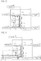
- FIG. 3 is a circuit diagram showing operation of the power supply device of FIG. 2 .
- FIG. 4 is a circuit diagram showing operation of the power supply device of FIG. 2 .
- FIG. 5 is a circuit diagram showing operation of the power supply device of FIG. 2 .
- FIG. 6 is a circuit diagram showing operation of the power supply device of FIG. 2 .
- FIG. 7 is a circuit diagram showing operation of the power supply device of FIG. 2 .
- FIG. 8 is a circuit diagram showing operation of the power supply device of FIG. 2 .
- FIG. 9 is a circuit diagram showing operation of the power supply device of FIG. 2 .
- FIG. 10 is a circuit diagram showing a power supply device of a second embodiment.
- an automatic driving control device 1 includes an automatic driving control ECU 2 , where detection signals from various sensors 3 , a monitoring camera 4 , a radar 5 , an ultrasonic sensor 6 , a communications antenna 7 , and the like are input.
- the various sensors 3 are a large number of sensors that acquire various external information such as wheel rotation speed information, acceleration information, inertia information, wheel angle information, outside temperature information, and the like of an automobile.
- the monitoring camera 4 is a camera that detects obstacles, moving bodies, or human bodies in the front, rear, left, and right surroundings of the automobile, and outputs a detection signal to the automatic driving control ECU 2 .
- the radar 5 detects moving bodies located forward and rearward in a medium to long distance that is comparatively far from the automobile, and outputs a detection signal to the automatic driving control ECU 2 .
- the ultrasonic sensor 6 detects obstacles at a short distance when the automobile starts moving or stops, and outputs a detection signal to the automatic driving control ECU 2 .
- the communications antenna 7 acquires control information such as map information, GPS information, DGPS information, and weather forecasts by communications, and outputs the acquired information to the automatic driving control ECU 2 through an external communications ECU (not shown).
- control information such as map information, GPS information, DGPS information, and weather forecasts by communications
- the automatic driving control ECU 2 controls an engine control ECU 8 , an electric steering device 9 , and an electric brake device 10 based on the above detection signals and control information.
- the automatic driving control device 1 can control or execute driving of the automobile without requiring operation by a driver.
- Electric power is supplied from a power supply device 11 to the automatic driving control device 1 as described above. Next, the power supply device 11 will be described.
- first and second batteries 13 and 14 As shown in FIG. 2 , first and second batteries 13 and 14 , an alternator 15 , and first and second load groups 16 and 17 are connected to a power box 12 . Electric power is supplied from the first and second batteries 13 and 14 or the alternator 15 through the power box 12 to the first and second load groups 16 and 17 .
- the same type of lead battery is used for the first and second batteries 13 and 14 .
- the power box 12 includes a semiconductor relay 18 , fuses 19 a to 19 e , a current sensor 20 , a power auxiliary circuit 21 , and a controller 22 .
- output power of the alternator 15 is supplied through the fuse 19 a to one terminal t 1 of the semiconductor relay 18 .
- Output power of the first battery 13 is supplied through the fuse 19 b to the terminal t 1 of the semiconductor relay 18 .
- Output power of the second battery 14 is supplied through the fuse 19 c to another terminal t 2 of the semiconductor relay 18 .
- the current sensor 20 is disposed in the vicinity of the terminal t 2 , and the current sensor 20 can detect a current value and a current direction of current that flows in the semiconductor relay 18 . Also, the detection signal of the current sensor 20 is input to the controller 22 .
- the current sensor 20 is configured with a Hall sensor.
- the current sensor 20 may be provided with a voltage detection unit that detects voltage at both terminals t 1 and t 2 of the semiconductor relay 18 , and a current detection unit that detects the current direction and the current value of current that flows through the semiconductor relay 18 based on a potential difference between the terminals t 1 and t 2 of the semiconductor relay 18 , and the voltage detection unit and the current detection unit may be included in the controller 22 .
- a current sensor 23 capable of detecting a current value of current that flows through the second battery 14 is disposed in a ground-side terminal of the second battery 14 .
- the current sensor 23 is configured with a Hall sensor, for example.
- a detection signal of the current sensor 23 is output to the controller 22 .
- the controller 22 controls opening/closing of the semiconductor relay 18 based on detection signals output from the current sensors 20 and 23 .
- the power auxiliary circuit 21 is configured with a diode 24 and a capacitor 25 .
- the terminal t 1 of the semiconductor relay 18 is connected through the diode 24 and the fuse 19 d to the first load group 16 .
- a cathode terminal of the diode 24 is connected to a ground potential (for example, the vehicle body) through the capacitor 25 .
- the capacitor 25 is charged until the output voltage of the capacitor 25 becomes equal to the output voltage of the first battery 13 .
- the other terminal t 2 of the semiconductor relay 18 is connected through the fuse 19 e to the second load group 17 .
- the plurality of loads constituting the first and second load groups 16 and 17 include first and second redundant system loads allocated respectively to the first and second load groups 16 and 17 , such that even if the operation of one load group becomes unstable, it can be complemented with operation of the other load group.
- Each load of the third load group is configured to receive power supply from both the first battery 13 and the second battery 14 , and for example, is an abnormality display device (a navigation display or a meter), an air bag, or the like.
- the power supply device 11 (preferably the power box 12 ) includes a first power supply path w 1 where power is supplied from the first battery 13 to the first load group 16 , and a second power supply path w 2 where power is supplied from the second battery 14 to the second load group 17 .
- the first power supply path w 1 and the second power supply path w 2 are connected through the semiconductor relay 18 .
- the semiconductor relay 18 is kept in a conductive state by the controller 22 , and electric power is supplied from at least any of the first battery 13 and the second battery 14 to the first load group 16 and the second load group 17 .
- the electric power supplied to the second load group 17 is instantaneously interrupted during about 100 msec from when the short circuit current Is 1 starts to flow to when the fuse 19 a is blown, and the operation of the second load group 17 becomes unstable.
- the required power is supplied from the capacitor 25 during about 100 msec until the fuse 19 a is blown, so the first load group 16 operates stably.
- the fuse 19 a After the fuse 19 a is blown, power supply from the first and second batteries 13 and 14 to the first and second load groups 16 and 17 is restored, and the first load group 16 continues normal operation.
- the ECU or the like may enter a reset state and not return to normal operation. In this case, the automobile is safely automatically driven by operation of the first load group 16 , or alternatively, the automobile can be safely moved to a repair location by operation by a driver.
- a short circuit current Is 2 that flows from the second battery 14 to the semiconductor relay 18 is significantly larger than the current that flows in the semiconductor relay 18 during normal operation, so the short circuit current Is 2 is detected by the current sensor 20 , and the current sensor 20 outputs a detection signal S 1 to the controller 22 .
- the controller 22 sets the semiconductor relay 18 to a nonconductive state based on the detection signal S 1 , but the time from when the short circuit current Is 2 starts flowing until the semiconductor relay 18 becomes nonconductive is about 10 ⁇ sec, and is significantly shorter than the time until the fuse 19 a blows.
- the short circuit current Is 1 continues to flow from the first battery 13 , so an instantaneous interruption occurs in the electric power supplied to the first load group 16 , and operation of the first load group 16 becomes unstable.
- the second load group 17 is operating normally, the automobile is safely automatically driven, or alternatively, the automobile can be safely moved to a repair location by operation by a driver.
- the short circuit current Is 4 that flows from the second battery 14 to the semiconductor relay 18 is significantly larger than the current that flows in the semiconductor relay 18 during normal operation, so the short circuit current Is 4 is detected by the current sensor 20 , and the current sensor 20 outputs the detection signal S 1 to the controller 22 .
- the controller 22 sets the semiconductor relay 18 to a nonconductive state based on the detection signal S 1 , but the time from when the short circuit current Is 4 starts flowing until the semiconductor relay 18 becomes nonconductive is about 10 ⁇ sec, and is significantly shorter than the time until the fuse 19 b blows.
- the short circuit current Is 3 continues to flow from the first battery 13 until the fuse 19 b is blown, so an instantaneous interruption occurs in the electric power supplied to the first load group 16 , and operation of the first load group 16 becomes unstable.
- the second load group 17 is operating normally, the automobile is safely automatically driven, or alternatively, the automobile can be safely moved to a repair location by operation by a driver.
- the short circuit current Is 5 that flows from the first battery 13 to the semiconductor relay 18 is significantly larger than the current that flows in the semiconductor relay 18 during normal operation, so the short circuit current Is 5 is detected by the current sensor 20 , and the current sensor 20 outputs the detection signal S 1 to the controller 22 .
- the controller 22 sets the semiconductor relay 18 to a nonconductive state based on the detection signal S 1 , but the time from when the short circuit current Is 5 starts flowing until the semiconductor relay 18 becomes nonconductive is about 10 ⁇ sec, and is significantly shorter than the time until the fuse 19 c blows.
- the short circuit current Is 6 continues to flow from the second battery 14 until the fuse 19 c is blown, so an instantaneous interruption occurs in the electric power supplied to the second load group 17 , and operation of the second load group 17 becomes unstable. Also, after the fuse 19 c is blown, supply of electric power from the second battery 14 is stopped, and the semiconductor relay 18 also is nonconductive, so electric power is not supplied to the second load group 17 .
- the automobile is safely automatically driven, or alternatively, the automobile can be safely moved to a repair location by operation by a driver.
- the controller 22 detects that the difference between the current values detected by the current sensors 20 and 23 is large based on the detection signals S 1 and S 2 output from the current sensors 20 and 23 , and sets the semiconductor relay 18 to a nonconductive state.
- the semiconductor relay 18 is immediately set to a nonconductive state, the electric power supplied to the first load group 16 is not instantaneously interrupted, and the first load group 16 operates normally.
- the short circuit current Is 8 that flows from the second battery 14 to the semiconductor relay 18 is significantly larger than the current that flows in the semiconductor relay 18 during normal operation, so the short circuit current Is 8 is detected by the current sensor 20 , and the current sensor 20 outputs the detection signal S 1 to the controller 22 .
- the controller 22 sets the semiconductor relay 18 to a nonconductive state based on the detection signal S 1 , but the time from when the short circuit current Is 8 starts flowing until the semiconductor relay 18 becomes nonconductive is about 10 ⁇ sec, and is significantly shorter than the time until the fuse 19 d blows.
- the short circuit current Is 7 continues to flow from the first battery 13 until the fuse 19 d is blown, so an instantaneous interruption occurs in the electric power supplied to the first load group 16 , and operation of the first load group 16 becomes unstable. Also, after the fuse 19 d blows, power is not supplied to the first load group 16 .
- the automobile is safely automatically driven, or alternatively, the automobile can be safely moved to a repair location by operation by a driver.
- the electric power supplied from the first battery 13 to the first load group 16 is in an instantaneous interruption state, but until the fuse 19 e is blown, electric power is supplied from the power auxiliary circuit 21 to the first load group 16 , so an instantaneous interruption is prevented.
- a capacitor 26 may be connected as a power auxiliary circuit to the first load group 16 to prevent instantaneous interruption.
- the capacitor 26 is normally charged, and when electric power supplied from the first battery 13 to the first load group 16 is instantaneously interrupted, electric power is supplied from the capacitor 26 to the first load group 16 .
- the power supply paths w 1 and w 2 , the semiconductor relay 18 , the current sensors 20 and 23 , the power auxiliary circuit 21 , and the controller 22 cooperate to function as an instantaneous interruption prevention device.
- the power supply device 11 includes the plurality of fuses 19 a to 19 e , and the instantaneous interruption prevention device connected to the first and second load groups 16 and 17 . According to this configuration, it is possible to prevent instantaneous interruption of electric power supplied to at least any of the first and second load groups 16 and 17 when one or more of the fuses are blown. For example, even if a short circuit fault occurs in the first power supply path w 1 or the second power supply path w 2 between the first and second batteries 13 and 14 and the alternator 15 , and the first load group 16 and the second load group 17 , it is possible to supply stable electric power to at least any of the first load group 16 and the second load group 17 . In an automobile in which the first and second redundant system loads that complement operation of each other are allocated to the first load group 16 and the second load group 17 , the load of at least any among the redundant system loads can operate normally, so it is possible to insure safe running of the automobile.
- the semiconductor relay 18 can be quickly set to a nonconductive state before a fuse blows. Therefore, it is possible to prevent instantaneous interruption of electric power supplied to any one of the load groups.
- a second embodiment will be described with reference to FIG. 10 .
- the second embodiment discloses a power supply device that supplies power to third and fourth load groups 28 and 30 in addition to the first and second load groups 16 and 17 of the first embodiment.
- the same constituent elements as in the first embodiment are denoted by the same reference signs.
- the third load group 28 rather than a redundant system load, a load is connected that is not allowed to fail in order to maintain safe running of the automobile. Also, electric power is supplied to the third load group 28 from the terminal t 1 through the fuse 19 d and a diode 27 a , and from the terminal t 2 through the fuse 19 e and a diode 27 b.
- the fourth load group 30 a load is connected that does not interfere with safe running even if the load fails. Electric power is supplied to the fourth load group 30 from the terminal t 1 through a relay 29 , and when a short circuit fault is detected by the current sensors 20 and 23 , the controller 22 controls the relay 29 to be nonconductive. Other parts of the configuration are the same as in the first embodiment.
- the relay 29 is set to a nonconductive state, so power supply to the fourth load group 30 can be stopped. Therefore, when a short circuit fault occurs, power supply is proactively stopped for a load that does not interfere with safe running even if electric power is not supplied, so the automobile can be safely moved to a repair location while saving power.
- a switch circuit capable of cutting off the short circuit current before a fuse blows may be used.
- the power auxiliary circuit 21 may be changed to a power auxiliary circuit connected to both second load groups, or may be changed to one or a plurality of power auxiliary circuits connected to both the first and second load groups.
- the controller 22 may also be a microcomputer provided with software configured to execute the operations described in the present specification.
- a system that includes a power box 12 including a plurality of power-side connectors and a plurality of load-side connectors, a plurality of batteries 13 and 14 connected respectively to the plurality of power-side connectors of the power box 12 , and a plurality of load groups 16 and 17 connected respectively to the plurality of load-side connectors of the power box 12 , may also be referred to as an automotive electrical system.
Landscapes
- Engineering & Computer Science (AREA)
- Power Engineering (AREA)
- Mechanical Engineering (AREA)
- Charge And Discharge Circuits For Batteries Or The Like (AREA)
- Direct Current Feeding And Distribution (AREA)
- Control Of Driving Devices And Active Controlling Of Vehicle (AREA)
- Control Of Charge By Means Of Generators (AREA)
- Protection Of Static Devices (AREA)
Abstract
Description
-
- Loads having the same function and located on the left and right or front and rear. For example, an automatic driving ECU (for example, a first automatic driving ECU and a second automatic driving ECU), a head lamp (for example, a right head lamp and a left head lamp), a brake lamp (for example, a right brake lamp and a left brake lamp), a door lock mechanism (for example, a right door lock mechanism and a left door lock mechanism), or the like. For example, the right head lamp among the head lamps is a first redundant system load included in the
first load group 16, and a left head lamp is a second redundant system load included in thesecond load group 17. Due to redundant load allocation, even if operation of the right head lamp becomes unstable or impossible, front lighting is insured by the left head lamp. - Components that have the same function and can be substituted. For example, such as an electric shifter and an electric parking brake, or a peripheral camera and an obstacle detection device.
- Loads having the same function and located on the left and right or front and rear. For example, an automatic driving ECU (for example, a first automatic driving ECU and a second automatic driving ECU), a head lamp (for example, a right head lamp and a left head lamp), a brake lamp (for example, a right brake lamp and a left brake lamp), a door lock mechanism (for example, a right door lock mechanism and a left door lock mechanism), or the like. For example, the right head lamp among the head lamps is a first redundant system load included in the
Claims (6)
Applications Claiming Priority (3)
| Application Number | Priority Date | Filing Date | Title |
|---|---|---|---|
| JP2015003080A JP6432355B2 (en) | 2015-01-09 | 2015-01-09 | Automotive power supply device and power supply box |
| JP2015-003080 | 2015-01-09 | ||
| PCT/JP2016/050425 WO2016111340A1 (en) | 2015-01-09 | 2016-01-08 | Automobile power supply device and power box |
Publications (2)
| Publication Number | Publication Date |
|---|---|
| US20180001850A1 US20180001850A1 (en) | 2018-01-04 |
| US10654430B2 true US10654430B2 (en) | 2020-05-19 |
Family
ID=56356025
Family Applications (1)
| Application Number | Title | Priority Date | Filing Date |
|---|---|---|---|
| US15/541,412 Expired - Fee Related US10654430B2 (en) | 2015-01-09 | 2016-01-08 | Automotive power supply device and power box |
Country Status (4)
| Country | Link |
|---|---|
| US (1) | US10654430B2 (en) |
| JP (1) | JP6432355B2 (en) |
| CN (1) | CN107107843B (en) |
| WO (1) | WO2016111340A1 (en) |
Cited By (1)
| Publication number | Priority date | Publication date | Assignee | Title |
|---|---|---|---|---|
| US20210391708A1 (en) * | 2020-06-15 | 2021-12-16 | Eberspächer Controls Landau Gmbh & Co. Kg | On-board power supply system for a vehicle |
Families Citing this family (53)
| Publication number | Priority date | Publication date | Assignee | Title |
|---|---|---|---|---|
| CN109689437B (en) * | 2016-09-15 | 2020-07-03 | 日产自动车株式会社 | Vehicle control method and vehicle control device |
| EP3533668B1 (en) * | 2016-10-28 | 2021-01-06 | Nissan Motor Co., Ltd. | Vehicular power supply system control method and vehicular power supply system |
| DE102016122444A1 (en) * | 2016-11-22 | 2018-05-24 | HELLA GmbH & Co. KGaA | Two voltage battery |
| JP6702214B2 (en) | 2017-01-31 | 2020-05-27 | トヨタ自動車株式会社 | Power supply and vehicle |
| JP7248376B2 (en) * | 2017-02-16 | 2023-03-29 | 株式会社デンソー | vehicle |
| DE102017104958B4 (en) * | 2017-03-09 | 2024-03-14 | Dr. Ing. H.C. F. Porsche Aktiengesellschaft | Battery storage system |
| WO2018179625A1 (en) | 2017-03-30 | 2018-10-04 | 本田技研工業株式会社 | Vehicle control system, vehicle control method, vehicle control device, and vehicle control program |
| JP2018182864A (en) * | 2017-04-10 | 2018-11-15 | 株式会社デンソー | Power control device and power control method |
| JP6776989B2 (en) * | 2017-04-12 | 2020-10-28 | 株式会社デンソー | Travel control device |
| WO2019058869A1 (en) | 2017-09-22 | 2019-03-28 | 株式会社デンソー | Power supply system |
| JP6930505B2 (en) * | 2017-09-22 | 2021-09-01 | 株式会社デンソー | Power system |
| JP2019018836A (en) * | 2017-12-28 | 2019-02-07 | パナソニックIpマネジメント株式会社 | vehicle |
| GB2571518A (en) * | 2018-02-08 | 2019-09-04 | Jaguar Land Rover Ltd | An energy storage backup system |
| WO2019163492A1 (en) * | 2018-02-20 | 2019-08-29 | 日立オートモティブシステムズ株式会社 | Vehicle control device |
| JP7102773B2 (en) * | 2018-02-22 | 2022-07-20 | トヨタ自動車株式会社 | Vehicle power supply system |
| JP6738847B2 (en) * | 2018-03-13 | 2020-08-12 | 矢崎総業株式会社 | Vehicle power supply system |
| JP6816740B2 (en) * | 2018-04-23 | 2021-01-20 | 株式会社デンソーエレクトロニクス | Load drive |
| US12017666B2 (en) | 2018-07-16 | 2024-06-25 | Nissan Motor Co., Ltd. | Driving assisted vehicle control method and control system |
| DE102018212405B4 (en) * | 2018-07-25 | 2025-11-20 | Volkswagen Aktiengesellschaft | Traction network and method for operating a traction network of an electrically powered vehicle in the event of a short circuit |
| CN109383425B (en) * | 2018-12-04 | 2021-08-31 | 奇瑞汽车股份有限公司 | Power supply system, method and device of fuel intelligent automobile and storage medium |
| JP7014144B2 (en) * | 2018-12-12 | 2022-02-01 | 株式会社オートネットワーク技術研究所 | Power distributor |
| CN109466478B (en) * | 2018-12-21 | 2020-10-09 | 鄂尔多斯市普渡科技有限公司 | Distributed power supply system for unmanned vehicle |
| JP7115302B2 (en) * | 2018-12-27 | 2022-08-09 | 株式会社豊田自動織機 | Backup power supply for autonomous vehicles |
| JP6909245B2 (en) * | 2019-02-18 | 2021-07-28 | 矢崎総業株式会社 | Power distribution system |
| DE102019105504A1 (en) * | 2019-03-05 | 2020-09-10 | Audi Ag | Energy network for a motor vehicle and method for operating an energy network for a motor vehicle |
| JP7191750B2 (en) * | 2019-03-26 | 2022-12-19 | 株式会社デンソーテン | power control unit |
| JP7205343B2 (en) * | 2019-03-27 | 2023-01-17 | 株式会社デンソー | Mobile power supply system |
| CN112078366B (en) * | 2019-06-12 | 2022-01-21 | 广州汽车集团股份有限公司 | Electric vehicle and dual-power control system thereof |
| DE102019209026A1 (en) * | 2019-06-21 | 2020-12-24 | HELLA GmbH & Co. KGaA | On-board network and power module for such |
| JP7156200B2 (en) | 2019-07-26 | 2022-10-19 | 株式会社デンソー | power system |
| CN110481468B (en) * | 2019-08-16 | 2023-02-24 | 重庆长安汽车股份有限公司 | Automobile dual-power system for L3-level automatic driving and automobile |
| WO2021039130A1 (en) * | 2019-08-28 | 2021-03-04 | 株式会社デンソー | Energization control device and power supply unit |
| JP2021035272A (en) * | 2019-08-28 | 2021-03-01 | 株式会社デンソー | Energization control device and power supply unit |
| JP7339072B2 (en) * | 2019-08-30 | 2023-09-05 | トヨタ自動車株式会社 | network system |
| CN112751408A (en) * | 2019-10-31 | 2021-05-04 | 上海汽车集团股份有限公司 | Power supply circuit and power supply method |
| GB2590458B (en) * | 2019-12-19 | 2024-07-17 | Dyson Technology Ltd | Electric vehicle power system bus management |
| JP6990732B2 (en) * | 2020-03-17 | 2022-01-12 | 本田技研工業株式会社 | Power supply device and vehicle |
| JP7409206B2 (en) * | 2020-04-09 | 2024-01-09 | 株式会社デンソー | power system |
| JP7310701B2 (en) * | 2020-05-13 | 2023-07-19 | 株式会社デンソー | Controller and power system |
| JP7120276B2 (en) * | 2020-07-27 | 2022-08-17 | 株式会社デンソー | travel control device |
| US11979052B2 (en) | 2020-09-08 | 2024-05-07 | Denso Ten Limited | Power source device |
| CN112260394B (en) * | 2020-10-26 | 2023-10-10 | 东风商用车有限公司 | Redundant system of automobile power supply loop |
| CN112693412B (en) * | 2020-12-24 | 2022-03-15 | 奇瑞汽车股份有限公司 | Power distribution system of automobile and automobile |
| US12100978B2 (en) * | 2021-01-08 | 2024-09-24 | Dell Products L.P. | Configurable network for enabling efficient charging and loading of two battery cells |
| JP7563994B2 (en) * | 2021-01-13 | 2024-10-08 | 株式会社デンソーテン | On-board power supply device and on-board power supply control method |
| CN115021386A (en) * | 2021-03-05 | 2022-09-06 | 上海汽车集团股份有限公司 | A vehicle power supply system |
| JP7651900B2 (en) * | 2021-03-25 | 2025-03-27 | 株式会社オートネットワーク技術研究所 | Anomaly detection device and anomaly detection method |
| JP7689850B2 (en) * | 2021-03-29 | 2025-06-09 | 株式会社デンソーテン | power supply |
| JP7710344B2 (en) * | 2021-09-13 | 2025-07-18 | 株式会社デンソーテン | Power supply control device and power supply control method |
| US20230108060A1 (en) * | 2021-10-06 | 2023-04-06 | Sudarshan S Krishnamoorthy | System and method for providing uninterruptible power supply using one or more energy sources |
| CN114211962A (en) * | 2021-12-08 | 2022-03-22 | 华人运通(江苏)技术有限公司 | Low-voltage power supply management system of electric automobile and electric automobile |
| JP2023121363A (en) * | 2022-02-21 | 2023-08-31 | トヨタ自動車株式会社 | In-vehicle system, method, program, and vehicle |
| JP2025080442A (en) * | 2023-11-14 | 2025-05-26 | 株式会社オートネットワーク技術研究所 | power supply device |
Citations (9)
| Publication number | Priority date | Publication date | Assignee | Title |
|---|---|---|---|---|
| JP2001037070A (en) | 1999-07-26 | 2001-02-09 | Auto Network Gijutsu Kenkyusho:Kk | Vehicle power supply |
| US20050248968A1 (en) * | 2004-05-10 | 2005-11-10 | Delta Electronics, Inc. | Voltage adapter capable of conserving power consumption under standby mode |
| JP2007336631A (en) | 2006-06-12 | 2007-12-27 | Toyota Motor Corp | Power system |
| US7742273B1 (en) * | 2006-07-31 | 2010-06-22 | Shvartsman Vladimir A | Self-protected, intelligent, power control module |
| JP2010148318A (en) | 2008-12-22 | 2010-07-01 | Honda Motor Co Ltd | Dc/dc converter system |
| US20110018441A1 (en) * | 2007-07-26 | 2011-01-27 | Panasonic Electric Works Co., Ltd. | Vehicle-mounted load controller, vehicle-mounted headlight device, and vehicle-mounted taillight device |
| US20120296506A1 (en) | 2011-05-17 | 2012-11-22 | Mazda Motor Corporation | Power-supply control apparatus of vehicle |
| US8854087B2 (en) * | 2012-09-28 | 2014-10-07 | Infineon Technologies Austria Ag | Electronic circuit with a reverse conducting transistor device |
| WO2015174379A1 (en) * | 2014-05-12 | 2015-11-19 | 株式会社オートネットワーク技術研究所 | Automobile power source device |
Family Cites Families (10)
| Publication number | Priority date | Publication date | Assignee | Title |
|---|---|---|---|---|
| JP2003226027A (en) * | 2002-02-01 | 2003-08-12 | Sharp Corp | Ink remaining amount display device, ink remaining amount display method, ink remaining amount display program, and recording medium recording this program |
| JP3685326B2 (en) * | 2002-02-06 | 2005-08-17 | 矢崎総業株式会社 | Power supply system for vehicles |
| JP2004338577A (en) * | 2003-05-16 | 2004-12-02 | Hitachi Ltd | Vehicle power supply device and power supply method |
| JP2006021610A (en) * | 2004-07-07 | 2006-01-26 | Yazaki Corp | Vehicle load control device |
| JP5343787B2 (en) * | 2009-09-18 | 2013-11-13 | トヨタ自動車株式会社 | Electrical system |
| US8884582B2 (en) * | 2010-10-19 | 2014-11-11 | Alte Powertrain Technologies, Inc. | Battery management system utilizing stackable batteries |
| CN202455044U (en) * | 2011-11-25 | 2012-09-26 | 深圳市比亚迪锂电池有限公司 | Power battery set possessing short circuit and overload protection function |
| JP5825107B2 (en) * | 2012-01-11 | 2015-12-02 | スズキ株式会社 | Vehicle power supply |
| JP5982632B2 (en) * | 2012-03-30 | 2016-08-31 | パナソニックIpマネジメント株式会社 | In-vehicle power supply circuit and in-vehicle power supply unit using the same |
| CN203151375U (en) * | 2013-01-29 | 2013-08-21 | 湖南南车时代电动汽车股份有限公司 | Unidirectional boost-buck large power DC/DC converter and hybrid power vehicle |
-
2015
- 2015-01-09 JP JP2015003080A patent/JP6432355B2/en not_active Expired - Fee Related
-
2016
- 2016-01-08 CN CN201680004647.9A patent/CN107107843B/en not_active Expired - Fee Related
- 2016-01-08 US US15/541,412 patent/US10654430B2/en not_active Expired - Fee Related
- 2016-01-08 WO PCT/JP2016/050425 patent/WO2016111340A1/en not_active Ceased
Patent Citations (11)
| Publication number | Priority date | Publication date | Assignee | Title |
|---|---|---|---|---|
| JP2001037070A (en) | 1999-07-26 | 2001-02-09 | Auto Network Gijutsu Kenkyusho:Kk | Vehicle power supply |
| US20050248968A1 (en) * | 2004-05-10 | 2005-11-10 | Delta Electronics, Inc. | Voltage adapter capable of conserving power consumption under standby mode |
| JP2007336631A (en) | 2006-06-12 | 2007-12-27 | Toyota Motor Corp | Power system |
| US7742273B1 (en) * | 2006-07-31 | 2010-06-22 | Shvartsman Vladimir A | Self-protected, intelligent, power control module |
| US20110018441A1 (en) * | 2007-07-26 | 2011-01-27 | Panasonic Electric Works Co., Ltd. | Vehicle-mounted load controller, vehicle-mounted headlight device, and vehicle-mounted taillight device |
| JP2010148318A (en) | 2008-12-22 | 2010-07-01 | Honda Motor Co Ltd | Dc/dc converter system |
| US20120296506A1 (en) | 2011-05-17 | 2012-11-22 | Mazda Motor Corporation | Power-supply control apparatus of vehicle |
| JP2012240487A (en) | 2011-05-17 | 2012-12-10 | Mazda Motor Corp | Power supply control apparatus of vehicle |
| US8854087B2 (en) * | 2012-09-28 | 2014-10-07 | Infineon Technologies Austria Ag | Electronic circuit with a reverse conducting transistor device |
| WO2015174379A1 (en) * | 2014-05-12 | 2015-11-19 | 株式会社オートネットワーク技術研究所 | Automobile power source device |
| US20170080883A1 (en) * | 2014-05-12 | 2017-03-23 | Autonetworks Technologies, Ltd. | Automotive power unit |
Non-Patent Citations (1)
| Title |
|---|
| Search Report for International Application No. PCT/JP2016/050425, dated Mar. 15, 2016, 2 pp. |
Cited By (2)
| Publication number | Priority date | Publication date | Assignee | Title |
|---|---|---|---|---|
| US20210391708A1 (en) * | 2020-06-15 | 2021-12-16 | Eberspächer Controls Landau Gmbh & Co. Kg | On-board power supply system for a vehicle |
| US11626722B2 (en) * | 2020-06-15 | 2023-04-11 | Eberspächer Controls Landau Gmbh & Co. Kg | On-board power supply system for a vehicle |
Also Published As
| Publication number | Publication date |
|---|---|
| CN107107843B (en) | 2019-03-29 |
| US20180001850A1 (en) | 2018-01-04 |
| JP2016128283A (en) | 2016-07-14 |
| CN107107843A (en) | 2017-08-29 |
| WO2016111340A1 (en) | 2016-07-14 |
| JP6432355B2 (en) | 2018-12-05 |
Similar Documents
| Publication | Publication Date | Title |
|---|---|---|
| US10654430B2 (en) | Automotive power supply device and power box | |
| US11465574B2 (en) | Power supply system | |
| US10804714B2 (en) | Relay device and in-vehicle system | |
| US12155200B2 (en) | Control and operation of power distribution system | |
| US11742747B2 (en) | Power supply system | |
| US20190013664A1 (en) | On-vehicle power source switch apparatus and control apparatus | |
| US10861663B2 (en) | Relay device and a method to detect open-circuit failures | |
| US20170080883A1 (en) | Automotive power unit | |
| KR20220026873A (en) | Power control apparatus and method for autonomous vehicle | |
| US11618462B2 (en) | In-vehicle control system | |
| US10714288B2 (en) | Relay device | |
| US11097675B2 (en) | Vehicular power supply system | |
| WO2017208751A1 (en) | Relay device and power source device | |
| US11012020B2 (en) | Electronic control unit | |
| US20250035712A1 (en) | Ground fault detection apparatus | |
| US20240291273A1 (en) | Power source, supervisory apparatus and control system | |
| US20240302441A1 (en) | Power supply monitoring device | |
| US20190291581A1 (en) | Motor Vehicle with an Electric Motor, in Particular a Hybrid or Electric Vehicle | |
| US11667199B2 (en) | Motor vehicle with an electric motor, in particular a hybrid or electric vehicle | |
| US20250364800A1 (en) | Switch shut-off device for power supply system | |
| US20220102972A1 (en) | Power distribution system with redundancy to increase safety factor | |
| US12244163B2 (en) | Power supply system for electric vehicle | |
| US11458931B2 (en) | Wiper drive circuit | |
| WO2018186483A1 (en) | On-board electronic control device | |
| US20030107861A1 (en) | Method and apparatus for disconnecting a battery |
Legal Events
| Date | Code | Title | Description |
|---|---|---|---|
| AS | Assignment |
Owner name: SUMITOMO WIRING SYSTEMS, LTD., JAPAN Free format text: ASSIGNMENT OF ASSIGNORS INTEREST;ASSIGNOR:KONTANI, TSUYOSHI;REEL/FRAME:042883/0069 Effective date: 20170619 Owner name: AUTONETWORKS TECHNOLOGIES, LTD., JAPAN Free format text: ASSIGNMENT OF ASSIGNORS INTEREST;ASSIGNOR:KONTANI, TSUYOSHI;REEL/FRAME:042883/0069 Effective date: 20170619 Owner name: SUMITOMO ELECTRIC INDUSTRIES, LTD., JAPAN Free format text: ASSIGNMENT OF ASSIGNORS INTEREST;ASSIGNOR:KONTANI, TSUYOSHI;REEL/FRAME:042883/0069 Effective date: 20170619 |
|
| STPP | Information on status: patent application and granting procedure in general |
Free format text: DOCKETED NEW CASE - READY FOR EXAMINATION |
|
| STPP | Information on status: patent application and granting procedure in general |
Free format text: NON FINAL ACTION MAILED |
|
| STPP | Information on status: patent application and granting procedure in general |
Free format text: RESPONSE TO NON-FINAL OFFICE ACTION ENTERED AND FORWARDED TO EXAMINER |
|
| STPP | Information on status: patent application and granting procedure in general |
Free format text: NOTICE OF ALLOWANCE MAILED -- APPLICATION RECEIVED IN OFFICE OF PUBLICATIONS |
|
| ZAAA | Notice of allowance and fees due |
Free format text: ORIGINAL CODE: NOA |
|
| ZAAB | Notice of allowance mailed |
Free format text: ORIGINAL CODE: MN/=. |
|
| STPP | Information on status: patent application and granting procedure in general |
Free format text: PUBLICATIONS -- ISSUE FEE PAYMENT VERIFIED |
|
| STCF | Information on status: patent grant |
Free format text: PATENTED CASE |
|
| FEPP | Fee payment procedure |
Free format text: MAINTENANCE FEE REMINDER MAILED (ORIGINAL EVENT CODE: REM.); ENTITY STATUS OF PATENT OWNER: LARGE ENTITY |
|
| LAPS | Lapse for failure to pay maintenance fees |
Free format text: PATENT EXPIRED FOR FAILURE TO PAY MAINTENANCE FEES (ORIGINAL EVENT CODE: EXP.); ENTITY STATUS OF PATENT OWNER: LARGE ENTITY |
|
| STCH | Information on status: patent discontinuation |
Free format text: PATENT EXPIRED DUE TO NONPAYMENT OF MAINTENANCE FEES UNDER 37 CFR 1.362 |
|
| FP | Lapsed due to failure to pay maintenance fee |
Effective date: 20240519 |