US10620401B2 - Optical system and image pickup apparatus having the same - Google Patents
Optical system and image pickup apparatus having the same Download PDFInfo
- Publication number
- US10620401B2 US10620401B2 US15/606,843 US201715606843A US10620401B2 US 10620401 B2 US10620401 B2 US 10620401B2 US 201715606843 A US201715606843 A US 201715606843A US 10620401 B2 US10620401 B2 US 10620401B2
- Authority
- US
- United States
- Prior art keywords
- lens
- optical system
- positive lens
- positive
- object side
- Prior art date
- Legal status (The legal status is an assumption and is not a legal conclusion. Google has not performed a legal analysis and makes no representation as to the accuracy of the status listed.)
- Active, expires
Links
Images


Classifications
-
- G—PHYSICS
- G02—OPTICS
- G02B—OPTICAL ELEMENTS, SYSTEMS OR APPARATUS
- G02B15/00—Optical objectives with means for varying the magnification
- G02B15/14—Optical objectives with means for varying the magnification by axial movement of one or more lenses or groups of lenses relative to the image plane for continuously varying the equivalent focal length of the objective
- G02B15/143—Optical objectives with means for varying the magnification by axial movement of one or more lenses or groups of lenses relative to the image plane for continuously varying the equivalent focal length of the objective having three groups only
-
- G—PHYSICS
- G02—OPTICS
- G02B—OPTICAL ELEMENTS, SYSTEMS OR APPARATUS
- G02B9/00—Optical objectives characterised both by the number of the components and their arrangements according to their sign, i.e. + or -
- G02B9/12—Optical objectives characterised both by the number of the components and their arrangements according to their sign, i.e. + or - having three components only
- G02B9/14—Optical objectives characterised both by the number of the components and their arrangements according to their sign, i.e. + or - having three components only arranged + - +
- G02B9/24—Optical objectives characterised both by the number of the components and their arrangements according to their sign, i.e. + or - having three components only arranged + - + two of the components having compound lenses
- G02B9/26—Optical objectives characterised both by the number of the components and their arrangements according to their sign, i.e. + or - having three components only arranged + - + two of the components having compound lenses the front and rear components having compound lenses
-
- G—PHYSICS
- G02—OPTICS
- G02B—OPTICAL ELEMENTS, SYSTEMS OR APPARATUS
- G02B13/00—Optical objectives specially designed for the purposes specified below
- G02B13/02—Telephoto objectives, i.e. systems of the type + - in which the distance from the front vertex to the image plane is less than the equivalent focal length
-
- G—PHYSICS
- G02—OPTICS
- G02B—OPTICAL ELEMENTS, SYSTEMS OR APPARATUS
- G02B13/00—Optical objectives specially designed for the purposes specified below
- G02B13/18—Optical objectives specially designed for the purposes specified below with lenses having one or more non-spherical faces, e.g. for reducing geometrical aberration
-
- G—PHYSICS
- G02—OPTICS
- G02B—OPTICAL ELEMENTS, SYSTEMS OR APPARATUS
- G02B15/00—Optical objectives with means for varying the magnification
- G02B15/14—Optical objectives with means for varying the magnification by axial movement of one or more lenses or groups of lenses relative to the image plane for continuously varying the equivalent focal length of the objective
- G02B15/16—Optical objectives with means for varying the magnification by axial movement of one or more lenses or groups of lenses relative to the image plane for continuously varying the equivalent focal length of the objective with interdependent non-linearly related movements between one lens or lens group, and another lens or lens group
-
- G—PHYSICS
- G02—OPTICS
- G02B—OPTICAL ELEMENTS, SYSTEMS OR APPARATUS
- G02B27/00—Optical systems or apparatus not provided for by any of the groups G02B1/00 - G02B26/00, G02B30/00
- G02B27/0025—Optical systems or apparatus not provided for by any of the groups G02B1/00 - G02B26/00, G02B30/00 for optical correction, e.g. distorsion, aberration
-
- G—PHYSICS
- G02—OPTICS
- G02B—OPTICAL ELEMENTS, SYSTEMS OR APPARATUS
- G02B9/00—Optical objectives characterised both by the number of the components and their arrangements according to their sign, i.e. + or -
- G02B9/12—Optical objectives characterised both by the number of the components and their arrangements according to their sign, i.e. + or - having three components only
Definitions
- the present disclosure relates to an optical system and an image pickup apparatus having the same, and is suitable for an image pickup apparatus employing an image pickup element, such as a digital still camera, a video camera, a monitoring camera, a broadcast camera, or an image pickup apparatus such as a camera using silver-halide photography film.
- an image pickup element such as a digital still camera, a video camera, a monitoring camera, a broadcast camera, or an image pickup apparatus such as a camera using silver-halide photography film.
- a shooting optical system of a so-called telephoto-type in which an optical system having positive refractive power is arranged on the object side, and an optical system having negative refractive power is arranged on the image side is known as a shooting optical system having a long focal length.
- a shooting optical system of a telephoto-type is used, for example, in an ultra-telephoto lens having a fixed focal length.
- primary chromatic aberration and secondary spectrum increase with increase in focal length.
- Appropriately setting the balance between the amount of occurrence of chromatic aberration of a positive lens and the amount of correction of chromatic aberration by a negative lens is known as a method for reducing primary chromatic aberration.
- Using a lens formed of a material having anomalous dispersion is known as a method for reducing the secondary spectrum.
- the secondary spectrum is reduced by arranging a positive lens formed of a material having anomalous dispersion on the most object side.
- primary chromatic aberration is generally corrected by arranging a negative lens formed of a high dispersion material.
- a negative lens formed of a high dispersion material.
- the amount of occurrence and the amount of correction of chromatic aberration in the entire optical system are balanced by arranging a positive lens at a position relatively near to the positive lens arranged on the most object side. Because the positive and negative lenses arranged on the object side have large effective diameters and are likely to be heavy, it is difficult to sufficiently reduce the weight of the optical system of Japanese Patent Laid-Open No. 2015-215560.
- the present disclosure provides an optical system that is lightweight and in which aberrations such as chromatic aberration are satisfactorily corrected, and an image pickup apparatus having the same.
- an optical system includes a positive lens G 1 p , and a negative lens Gn located on the most object side among negative lenses arranged on the image side of the positive lens G 1 p .
- the positive lens G 1 p is a positive lens located on the most object side among positive lenses included in the optical system.
- FIG. 1 is a lens sectional view of an optical system of Embodiment 1.
- FIG. 2 is an aberration diagram of Embodiment 1 that is in focus at infinity.
- FIG. 3 is a lens sectional view of an optical system of Embodiment 2.
- FIG. 4 is an aberration diagram of Embodiment 2 that is in focus at infinity.
- FIG. 5 is a lens sectional view of an optical system of Embodiment 3.
- FIG. 6 is an aberration diagram of Embodiment 3 that is in focus at infinity.
- FIG. 7 is a lens sectional view of an optical system of Embodiment 4.
- FIG. 8 is an aberration diagram of Embodiment 4 that is in focus at infinity.
- FIG. 9 is a lens sectional view of an optical system of Embodiment 5.
- FIG. 10 is an aberration diagram of Embodiment 5 that is in focus at infinity.
- FIG. 11 is a lens sectional view of an optical system of Embodiment 6.
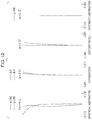
- FIG. 12 is an aberration diagram of Embodiment 6 that is in focus at infinity.
- FIG. 13 is a lens sectional view of an optical system of Embodiment 7.
- FIG. 14 is an aberration diagram of Embodiment 7 that is in focus at infinity.
- FIG. 15 is a schematic view of a main part of an image pickup apparatus of an embodiment.
- the optical system of the present embodiment includes a plurality of lenses.
- a positive lens arranged on the most object side among positive lenses included in an optical system is denoted as a positive lens G 1 p
- a negative lens located an the most object side among negative lenses arranged on the image side of the positive lens G 1 p is denoted as a negative lens Gn
- a positive lens arranged on the most object side among positive lenses arranged on the image side of the positive lens G 1 p is denoted as a positive lens G 1 p.
- FIG. 1 is a lens sectional view of an optical system of Embodiment 1.
- FIG. 2 is an aberration diagram of Embodiment 1 that is in focus at infinity.
- FIG. 3 is a lens sectional view of an optical system of Embodiment 2.
- FIG. 4 is an aberration diagram of Embodiment 2 that is in focus at infinity.
- FIG. 5 is a lens sectional view of an optical system of Embodiment 3.
- FIG. 6 is an aberration diagram of Embodiment 3 that is in focus at infinity.
- FIG. 7 is a lens sectional view f an optical system of Embodiment 4.
- FIG. 8 is an aberration diagram of Embodiment 4 that is in focus at infinity.
- FIG. 9 is a lens sectional view of an optical system of Embodiment 5.
- FIG. 10 is an aberration diagram of Embodiment 5 that is in focus at infinity.
- FIG. 11 is a lens sectional view of an optical system of Embodiment 6.
- FIG. 12 is an aberration diagram of Embodiment 6 that is in focus at infinity.
- FIG. 13 is a lens sectional view of an optical system of Embodiment 7,
- FIG. 14 is an aberration diagram of Embodiment 7 that is in focus at infinity.
- FIG. 15 is a schematic view of a main part of an image pickup apparatus having an optical system of an embodiment.
- the optical system of each embodiment is a shooting lens system used in an image pickup apparatus such as a video camera, a digital camera, a silver-halide film camera, or a TV camera.
- the left side is the object side (front side)
- the right side is the image side (rear side).
- i denotes the order of lens units from the object side to the image side
- Li denotes the i-th lens unit.
- the optical system of each embodiment includes, in order from the object side to the image side, a first lens unit L 1 having positive refractive power, a second lens unit L 2 having negative refractive power, and a third lens unit L 3 having positive or negative refractive power.
- the second lens unit L 2 moves, and the distances between adjacent lens units change.
- the term “lens unit” as used herein means one or more lens elements that move integrally during focusing. It only has to have one or more lenses, and does not necessarily have to have a plurality of lenses.
- SP denotes an aperture stop.
- the aperture stop SP is arranged between the first lens unit L 1 and the second lens unit L 2 .
- the aperture stop SP is arranged between the second lens unit L 2 and the third lens unit L 3 .
- the aperture stop SP is arranged inside the first lens unit L 1 .
- IP denotes an image plane.
- the image plane IP corresponds to a solid-state image pickup element (photoelectric conversion element) such as a CCD sensor or a CMOS sensor.
- the image plane IP corresponds to a film plane.
- Fno denotes an F-number
- spherical aberrations for the d-line (wavelength 587.6 nm) and the g-line (wavelength 435.8 nm) are shown.
- ⁇ S denotes the amount of astigmatism in a sagittal image plane
- ⁇ M denotes the amount of astigmatism in a meridional image plane.
- the distortion is for the d-line.
- chromatic aberration diagrams chromatic aberration for the g-line is shown.
- ⁇ denotes an image pickup half angle of view.
- the second lens unit L 2 moves, and the distances between adjacent lens units change.
- the second lens unit L 2 corresponds to a focusing unit.
- the second lens unit L 2 moves to the image side.
- the second lens unit L 2 moves to the object side.
- the imaging position can be changed by using some lenses of the optical system as an image stabilizing unit and moving the image stabilizing unit in a direction having a component perpendicular to the optical axis. Image blur correction can thereby be performed.
- Any one of the first lens unit L 1 , the second lens unit L 2 , and the third lens unit L 3 may be used as an image stabilizing unit, or some of the lenses included in a specific lens unit may be used as an image stabilizing unit.
- Abbe number ⁇ d and partial dispersion ratio ⁇ gF are known as parameters relating to correction of chromatic aberration in an optical system.
- the correction effect of primary chromatic aberration can be obtained.
- positive lenses arranged in a lens unit having positive refractive power as a whole are prone to primary chromatic aberration, the amount of occurrence of primary chromatic aberration can be reduced by using a low dispersion material as a material for positive lenses.
- a low dispersion material as a material for positive lenses.
- the distance between the positive lens G 1 p arranged on the most object side among positive lenses included in the optical system and the negative lens Gn located on the most object side among negative lenses arranged on the image side of the positive lens G 1 p is increased.
- the effective diameter of the negative lens Gn is thereby reduced.
- Increasing the distance between the positive lens G 1 p and the negative lens Gn decreases the height of the axial ray incident on the negative lens Gn, and therefore decreases the correction effect of spherical aberration in the negative lens Gn. Therefore, the spherical aberration occurring in the positive lens G 1 p needs to be reduced.
- the refractive power of the positive lens G 1 p is weakened, and the spherical aberration occurring in the positive lens G 1 p is reduced.
- weakening the refractive power of the positive lens G 1 p makes the amount of occurrence of primary chromatic aberration in the positive lens G 1 p insufficient relative to the amount of correction of primary chromatic aberration in the negative lens Gn.
- the amount of occurrence of primary chromatic aberration in the positive lens G 1 p is increased by forming the positive lens G 1 p of a relatively high dispersion material.
- optical system of each embodiment satisfies the following conditional expressions (1) to (4): LD/f ⁇ 1.00 (1), 0.25 ⁇ Dpn/LD ⁇ 0.50 (2), 1.45 ⁇ Nd 1 p ⁇ 1.68 (3), and 30.0 ⁇ d 1 p ⁇ 50.0 (4)
- the refractive index and Abbe number of the material of the positive lens G 1 p arranged on the most object side among positive lenses included in the optical system are respectively denoted as Nd1p and ⁇ d1p.
- the distance on the optical axis between the negative lens Gn arranged an the most object side among negative lenses arranged on the image side of the positive lens G 1 p and the positive lens G 1 p is denoted as Dpn.
- the focal length of the entire system is denoted as f, and the distance on the optical axis from the object side lens surface of the lens arranged on the most object side to the image plane (hereinafter referred to as total lens length) is denoted as LD.
- Conditional expression (1) shows that the total lens length LD is shorter than the focal length f of the entire optical system.
- an optical system mounted in a telephoto lens having a reduced total lens length has a focal length longer than the total lens length LD. It is undesirable that the total lens length LD is so long that the upper limit of conditional expression (1) is exceeded, because the optical system is increased in size in the optical axis direction.
- Conditional expression (2) defines the ratio of the distance Dpn on the optical axis between the negative lens Gn arranged on the most object side among negative lenses arranged on the image side of the positive lens G 1 p and the positive lens G 1 p to the total lens length LD. It is undesirable that the distance Dpn is so short that the lower limit of conditional expression (2) is exceeded, because the distance between the positive lens G 1 p and the negative lens Gn is too short, the effective diameter of the negative lens Gn increases, and the weight of the negative lens Gn increases. It is undesirable that the distance Dun is so longer that the upper limit of conditional expression. (2) is exceeded, because the height of the axial ray incident on the negative lens Gn decreases, and it is difficult to satisfactorily correct the spherical aberration in the negative lens Gn.
- Conditional expression (3) defines the refractive index Nd1p of the material of the positive lens G 1 p .
- a material having a refractive index exceeding the lower limit of conditional expression (3) is used as a material for the positive lens G 1 p .
- the refractive power of the positive lens G 1 p is too weak.
- a material having a refractive index exceeding the upper limit of conditional expression (3) is used as a material for the positive lens G 1 p , because a large amount of spherical aberration occurs in the positive lens G 1 p.
- Conditional expression (4) defines the Abbe number ⁇ d1p of the material of the positive lens G 1 p . It is undesirable that a material having an Abbe number exceeding the lower limit of conditional expression (4) is used as a material for the positive lens G 1 p , because excessive chromatic aberration occurs in the positive lens G 1 p , and it is difficult to appropriately correct the chromatic aberration occurring in the positive lens G 1 p in the negative lens Gn.
- a material having an Abbe number exceeding the upper limit of conditional expression (4) is used, the amount of chromatic aberration occurring in the positive lens G 1 p is insufficient, and the chromatic aberration to be generated in the positive lens arranged on the image side of the positive lens G 1 p increases. As a result, the positive lens arranged on the image side of the positive lens G 1 p needs to be arranged on the more object side, and the increase in weight of the optical system is caused. This is undesirable.
- elements are appropriately set so as to satisfy Conditional expressions (1) to (4).
- An optical system that is lightweight and in which aberrations such as spherical aberration and chromatic aberration are satisfactorily corrected can thereby be obtained.
- Conditional expressions (1) to (4) be set as follows: LD/f ⁇ 0.96 (1b), 0.25 ⁇ Dpn/LD ⁇ 0.40 (2b), 1.52 ⁇ Nd 1 p ⁇ 1.62 (3b), and 34.0 ⁇ d 1 p ⁇ 49.0 (4b).
- the positive lens G 1 p can have a meniscus shape convex toward the object side.
- the amount of occurrence of spherical aberration can be reduced compared to a case where the positive lens G 1 p has a biconvex shape.
- the partial dispersion ratio of the material of the positive lens G 1 p is denoted as ⁇ gF_G 1 p
- the radius of curvature of the object side lens surface of the positive lens G 1 p is denoted as R11
- the radius of curvature of the image side lens surface of the positive lens G 1 p is denoted as R12
- the focal length of the positive lens G 1 p is denoted as f1p
- the focal length of the entire system is denoted as f.
- the Abbe number and the refractive index of the material of the negative lens Gn are respectively denoted as ⁇ dn, and Ndn.
- the Abbe number of the material of the i-th negative lens counted from the object side among negative lenses arranged between the positive lens G 1 p and the focusing unit is denoted as ⁇ dni
- the focal length of the i-th negative lens is denoted as fni.
- the distance on the optical axis between the positive lens G 2 p located on the most object side among positive lenses arranged on the image side of the positive lens G 1 p and the positive lens G 1 p is denoted as Dpp
- the Abbe number and the partial dispersion ratio of the material of the positive lens G 2 p are respectively denoted as ⁇ d2p and ⁇ gF_G 2 p .
- the focal length of the positive lens G 2 p is denoted as f2p.
- Conditional expression (5) defines the anomalous dispersion ⁇ gF_G 1 p of the material of the positive lens G 1 p .
- the positive lens G 1 p By forming the positive lens G 1 p of a material having high anomalous dispersion, the secondary spectrum can be satisfactorily corrected. It is undesirable that a material having an anomalous dispersion exceeding the lower limit of Conditional expression (5) is used, because it is difficult to sufficiently correct the secondary spectrum, and as a result, it is difficult to reduce the secondary spectrum in the entire optical system. It is undesirable that a material having an anomalous dispersion exceeding the upper limit of Conditional expression (5) is used, because it is difficult to reduce the secondary spectrum in the entire optical system.
- Conditional expression (6) defines the shape of the positive lens G 1 p .
- the lower limit of Conditional expression (6) is exceeded, the difference in radius of curvature between the object side lens surface and the image side lens surface of the positive lens G 1 p is too small, and the positive refractive power of the positive lens G 1 p is too weak.
- the effective diameter of the lens arranged on the image side of the positive lens G 1 p increases, and the increase in weight of the entire optical system is caused. This is undesirable.
- Conditional expression (7) defines the ratio of the focal length f1p of the positive lens G 1 p and the focal length f of the entire system.
- the focal length f1p of the positive lens G 1 p is so short that the lower limit of Conditional expression (7) is exceeded, the refractive power of the positive lens G 1 p is too strong.
- a large amount of spherical aberration and longitudinal chromatic aberration occurs in the positive lens G 1 p . This is undesirable.
- the focal length f1p of the positive lens G 1 p is so long that the upper limit of Conditional expression (7) is exceeded, the refractive power of the positive lens G 1 p is too weak.
- it is difficult to sufficiently generate primary chromatic aberration and as a result, it is difficult to reduce primary chromatic aberration in the entire optical system. This is undesirable.
- Conditional expression (8) defines the Abbe number ⁇ dGn of the material of the negative lens Gn. It is undesirable that the lower limit of Conditional expression (8) is exceeded, because chromatic aberration is excessively corrected in the negative lens Gn. It is undesirable that the upper limit of Conditional expression (8) is exceeded, because it is difficult to sufficiently correct chromatic aberration in the negative lens Gn.
- Conditional expression (9) defines the refractive index Ndn of the material of the negative lens Gn. It is undesirable that the lower limit of Conditional expression (9) is exceeded, because it is difficult to satisfactorily correct spherical aberration. A material having a refractive index exceeding the upper limit of Conditional expression (9) lacks in practicality as a shooting optical system.
- Conditional expression (10) defines the relationship between the focal lengths fni of the negative lenses arranged between the positive lens G 1 p and the focusing unit, and the Abbe numbers ⁇ dni of the materials of the negative lenses arranged between the positive lens G 1 p and the focusing unit. It is undesirable that the lower limit of Conditional expression (10) is exceeded, because chromatic aberration is excessively corrected in the negative lenses arranged between the positive lens G 1 p and the focusing unit. It is undesirable that the upper limit of Conditional expression (10) is exceeded, because it is difficult to satisfactorily correct chromatic aberration in the negative lenses arranged between the positive lens G 1 p and the focusing unit.
- Conditional expression (11) defines the ratio of the distance Dpp on the optical axis between the positive lens G 2 p located on the most object side among positive lenses arranged on the image side of the positive lens G 1 p and the positive lens G 1 p to the total lens length LD. It is undesirable that the distance Dpp is so short that the lower limit of Conditional expression (11) is exceeded, because the effective diameter of the positive lens G 2 p increases, and the increase in weight of the positive lens G 2 p is caused. When the distance Dpp is so long that the upper limit of Conditional expression (11) is exceeded, because the height of the axial ray incident on the positive lens G 2 p decreases, and it is difficult to sufficiently generate primary chromatic aberration in the positive lens G 2 p . As a result, it is difficult to reduce primary chromatic aberration in the entire optical system. This is undesirable.
- Conditional expression (12) defines the anomalous dispersion ⁇ gF_G 2 p of the material of the positive lens G 2 p .
- the correction effect of the secondary spectrum can be obtained.
- a material having an anomalous dispersion exceeding the upper limit of conditional expression (12) is used as a material for the positive lens G 2 p , because the secondary spectrum is excessively corrected, and it is difficult to reduce the secondary spectrum in the entire optical system.
- a material having an anomalous dispersion exceeding the lower limit of conditional expression (12) is used as a material for the positive lens G 2 p , because it is difficult to satisfactorily correct the secondary spectrum.
- Conditional expression (13) defines the Abbe number ⁇ d2p of the material of the positive lens G 2 p . It is undesirable that a material having an Abbe number exceeding the lower limit of conditional expression (13), because chromatic aberration occurs excessively in the positive lens G 2 p.
- Conditional expression (14) defines the ratio of the focal length f2p of the positive lens G 2 p to the focal length f1p of the positive lens G 1 p .
- the focal length f2p of the positive lens G 2 p is so short that the lower limit of Conditional expression (14) is exceeded, the refractive power of the positive lens G 2 p is too strong.
- a large amount of spherical aberration and longitudinal chromatic aberration occurs in the positive lens G 2 p . This is undesirable.
- the focal length f2p of the positive lens G 2 p is so long that the upper limit of Conditional expression (14) is exceeded, the refractive power of the positive lens G 2 p is too weak.
- the effective diameter of the lens arranged on the image side of the positive lens G 2 p and the increase in weight of the entire optical system is caused. This is undesirable.
- Conditional expression (15) defines the ratio of the focal length f2p of the positive lens G 2 p and the focal length f of the entire system.
- the focal length f2p of the positive lens G 2 p is so short that the lower limit of Conditional expression (15) is exceeded, the refractive power of the positive lens G 2 p is too strong.
- a large amount of spherical aberration and longitudinal chromatic aberration occurs in the positive lens G 2 p . This is undesirable.
- the focal length f2p of the positive lens G 2 p is so long that the upper limit of Conditional expression (14) is exceeded, the refractive power of the positive lens G 2 p is too weak.
- the effective diameter of the lens arranged on the image side of the positive lens G 2 p increases, and the increase in weight of the entire optical system is caused. This is undesirable.
- Conditional expressions (5) to (15) be set as follows: 0.0010 ⁇ gF _ G 1 p ⁇ 0.6438+0.001682 ⁇ d 1 p ⁇ 0.0120 (5a), 0.55 ⁇ ( R 12 ⁇ R 11)/( R 12+ R 11) ⁇ 0.82 (6a), 0.40 ⁇ f 1 p/f ⁇ 0.90 (7a), 22.00 ⁇ dn ⁇ 36.00 (8a), 1.70 ⁇ Ndn ⁇ 2.10 (9a), 23.00 ⁇ ( ⁇ dni/fni )/ ⁇ (1/ fni ) ⁇ 40.00.
- the numerical value ranges of Conditional expressions (5) to (15) be set as follows: 0.0012 ⁇ gF _ G 1 p ⁇ 0.6438+0.001682 ⁇ d 1 p ⁇ 0.0100 (5b), 0.60 ⁇ ( R 12 ⁇ R 11)/( R 12+ R 11) ⁇ 0.80 (6b), 0.45 ⁇ f 1 p/f ⁇ 0.88 (7b), 24.00 ⁇ dn ⁇ 35.50 (8h), 1.73 ⁇ Ndn ⁇ 1.90 (9b), 25.00 ⁇ ( ⁇ dni/fni )/ ⁇ (1/ fni ) ⁇ 37.00 (10b), 0.22 ⁇ Dpp/LD ⁇ 0.40 (11b), 0.040 ⁇ gF _ G 2 p ⁇ 0.6438+0.001682 ⁇ d 2 p ⁇ 0.070 (12b), ⁇ d 2 p> 83.0 (13b), 0.38 ⁇ f 2 p/f 1 p ⁇ 0.65 (14h), and 0.25 ⁇ f 2/ f ⁇ 0.50 (15b
- i denotes the order of optical surfaces from the object side.
- ri denotes the curvature radius of the i-th optical surface (i-th surface), di denotes the distance between the i-th surface and the (i+1)th surface, and ndi and ⁇ di respectively denote the refractive index and the Abbe number of the material of the i-th optical member for the d-line.
- back focus is the air-conversion distance from the most image side surface of the optical system to the image side.
- Table 1 and Table 2 show the relationships between the above-described conditional expressions and Numerical Examples.
- ⁇ gF_Gi shows the numerical value of ⁇ gF_Gi ⁇ (0.6438 ⁇ 0.001682 ⁇ di).
- a protective glass for protecting lenses may be arranged on the object side of the first lens unit L 1 .
- a protective glass having an extremely weak refractive power shall not be included in the first lens unit L 1 .
- reference numeral 10 denotes a camera main body
- reference numeral 11 denotes a shooting optical system formed of any one of the optical systems described in Embodiments 1 to 7.
- Reference numeral 12 denotes a solid-state image pickup element (photoelectric conversion element) such as a CCD sensor or a CMOS sensor that is built in the camera main body 10 and that receives an object image formed by the shooting optical system 11 .
- an image pickup apparatus such as a digital still camera as described above, an image pickup apparatus that is lightweight and in which aberrations such as spherical aberration and chromatic aberration are satisfactorily corrected can be obtained.
Applications Claiming Priority (2)
| Application Number | Priority Date | Filing Date | Title |
|---|---|---|---|
| JP2016109658A JP6452645B2 (ja) | 2016-06-01 | 2016-06-01 | 光学系及びそれを有する撮像装置 |
| JP2016-109658 | 2016-06-01 |
Publications (2)
| Publication Number | Publication Date |
|---|---|
| US20170351060A1 US20170351060A1 (en) | 2017-12-07 |
| US10620401B2 true US10620401B2 (en) | 2020-04-14 |
Family
ID=60483207
Family Applications (1)
| Application Number | Title | Priority Date | Filing Date |
|---|---|---|---|
| US15/606,843 Active 2037-06-01 US10620401B2 (en) | 2016-06-01 | 2017-05-26 | Optical system and image pickup apparatus having the same |
Country Status (2)
| Country | Link |
|---|---|
| US (1) | US10620401B2 (ja) |
| JP (1) | JP6452645B2 (ja) |
Families Citing this family (4)
| Publication number | Priority date | Publication date | Assignee | Title |
|---|---|---|---|---|
| JP6452645B2 (ja) | 2016-06-01 | 2019-01-16 | キヤノン株式会社 | 光学系及びそれを有する撮像装置 |
| JP6381582B2 (ja) * | 2016-06-01 | 2018-08-29 | キヤノン株式会社 | 光学系及びそれを有する撮像装置 |
| JP6452646B2 (ja) | 2016-06-01 | 2019-01-16 | キヤノン株式会社 | 光学系及びそれを有する撮像装置 |
| GB2591312B (en) * | 2019-08-06 | 2022-02-09 | Canon Kk | Optical system and imaging apparatus |
Citations (30)
| Publication number | Priority date | Publication date | Assignee | Title |
|---|---|---|---|---|
| US6115188A (en) | 1997-10-16 | 2000-09-05 | Canon Kabushiki Kaisha | Optical system and optical apparatus having the same |
| US20060209426A1 (en) * | 2005-03-07 | 2006-09-21 | Fujinon Corporation | Telephoto lens |
| US7609446B2 (en) | 2006-11-16 | 2009-10-27 | Canon Kabushiki Kaisha | Zoom lens and image pickup apparatus including the lens |
| US7626771B2 (en) | 2007-12-05 | 2009-12-01 | Canon Kabushiki Kaisha | Optical system and optical apparatus including the same |
| US20110080654A1 (en) | 2009-10-05 | 2011-04-07 | Canon Kabushiki Kaisha | Optical system and optical device including the same |
| US20110310486A1 (en) * | 2010-06-16 | 2011-12-22 | Canon Kabushiki Kaisha | Photographic optical system and image pickup apparatus including the photographic optical system |
| US8223436B2 (en) | 2009-10-06 | 2012-07-17 | Canon Kabushiki Kaisha | Rear attachment lens, imaging optical system and image pickup apparatus |
| US8314996B2 (en) | 2009-12-25 | 2012-11-20 | Canon Kabushiki Kaisha | Zoom lens and image pickup apparatus including the same |
| US8331034B2 (en) | 2009-10-06 | 2012-12-11 | Canon Kabushiki Kaisha | Zoom lens system and image pickup apparatus including the same |
| US20130194487A1 (en) | 2012-01-30 | 2013-08-01 | Canon Kabushiki Kaisha | Image pickup optical system and image pickup apparatus having the same |
| JP2014026023A (ja) | 2012-07-25 | 2014-02-06 | Konica Minolta Inc | 望遠レンズ,撮像光学装置及びデジタル機器 |
| US8681433B2 (en) | 2011-03-10 | 2014-03-25 | Fujifilm Corporation | Variable magnification optical system and imaging apparatus |
| JP2014056195A (ja) | 2012-09-14 | 2014-03-27 | Canon Inc | 撮像光学系及びそれを有する撮像装置 |
| US8705180B2 (en) | 2011-05-30 | 2014-04-22 | Ricoh Company, Ltd. | Zoom lens, imaging device and information device |
| US20150109519A1 (en) | 2013-10-23 | 2015-04-23 | Olympus Corporation | Single Focal Length Lens System and Image Pickup Apparatus Using the Same |
| JP2015111254A (ja) | 2013-11-08 | 2015-06-18 | オリンパス株式会社 | 結像レンズ系及びそれを備えた撮像装置 |
| US9081170B2 (en) | 2010-11-04 | 2015-07-14 | Canon Kabushiki Kaisha | Zoom lens and image pickup apparatus including the same |
| US9134512B2 (en) | 2012-03-12 | 2015-09-15 | Canon Kabushiki Kaisha | Zoom lens and image pickup apparatus having the same |
| JP2015215560A (ja) | 2014-05-13 | 2015-12-03 | 株式会社ニコン | 光学系、光学装置、光学系の製造方法 |
| JP2015215561A (ja) | 2014-05-13 | 2015-12-03 | 株式会社ニコン | 光学系、光学装置、光学系の製造方法 |
| JP2016051100A (ja) | 2014-09-01 | 2016-04-11 | リコー光学株式会社 | インナーフォーカス式望遠レンズ |
| US20160109690A1 (en) | 2014-10-17 | 2016-04-21 | Olympus Corporation | Telephoto Lens and Image Pickup Apparatus Using the Same |
| JP2016148707A (ja) | 2015-02-10 | 2016-08-18 | オリンパス株式会社 | 望遠レンズ及びそれを有する撮像装置 |
| JP2016161644A (ja) | 2015-02-27 | 2016-09-05 | 株式会社ニコン | 撮影レンズ、撮影レンズを備えた光学機器、撮影レンズの製造方法 |
| US20170129801A1 (en) * | 2015-11-06 | 2017-05-11 | Ohara Inc. | Optical glass, preform, and optical element |
| US9678318B2 (en) | 2013-11-12 | 2017-06-13 | Canon Kabushiki Kaisha | Zoom lens and image pickup apparatus including the same |
| US20170351089A1 (en) | 2016-06-01 | 2017-12-07 | Canon Kabushiki Kaisha | Optical system and image pickup apparatus including the same |
| US20170351060A1 (en) | 2016-06-01 | 2017-12-07 | Canon Kabushiki Kaisha | Optical system and image pickup apparatus having the same |
| US9946065B2 (en) | 2015-08-21 | 2018-04-17 | Canon Kabushiki Kaisha | Zoom lens and image pickup apparatus including the same |
| US9983392B2 (en) | 2016-03-24 | 2018-05-29 | Konica Minolta, Inc. | Projection zoom lens and image projection apparatus |
Family Cites Families (2)
| Publication number | Priority date | Publication date | Assignee | Title |
|---|---|---|---|---|
| US4929071A (en) * | 1985-12-20 | 1990-05-29 | Lockheed Missiles & Space Company, Inc. | Long-focus color-corrected petzval-type optical objective |
| JP5639625B2 (ja) * | 2012-09-14 | 2014-12-10 | キヤノン株式会社 | 撮像光学系及びそれを有する撮像装置 |
-
2016
- 2016-06-01 JP JP2016109658A patent/JP6452645B2/ja active Active
-
2017
- 2017-05-26 US US15/606,843 patent/US10620401B2/en active Active
Patent Citations (35)
| Publication number | Priority date | Publication date | Assignee | Title |
|---|---|---|---|---|
| US6115188A (en) | 1997-10-16 | 2000-09-05 | Canon Kabushiki Kaisha | Optical system and optical apparatus having the same |
| US20060209426A1 (en) * | 2005-03-07 | 2006-09-21 | Fujinon Corporation | Telephoto lens |
| US7609446B2 (en) | 2006-11-16 | 2009-10-27 | Canon Kabushiki Kaisha | Zoom lens and image pickup apparatus including the lens |
| US7894135B2 (en) | 2006-11-16 | 2011-02-22 | Canon Kabushiki Kaisha | Zoom lens and image pickup apparatus including the lens |
| US7626771B2 (en) | 2007-12-05 | 2009-12-01 | Canon Kabushiki Kaisha | Optical system and optical apparatus including the same |
| US7948691B2 (en) | 2009-10-05 | 2011-05-24 | Canon Kabushiki Kaisha | Optical system and optical device including the same |
| US20110080654A1 (en) | 2009-10-05 | 2011-04-07 | Canon Kabushiki Kaisha | Optical system and optical device including the same |
| US8223436B2 (en) | 2009-10-06 | 2012-07-17 | Canon Kabushiki Kaisha | Rear attachment lens, imaging optical system and image pickup apparatus |
| US8331034B2 (en) | 2009-10-06 | 2012-12-11 | Canon Kabushiki Kaisha | Zoom lens system and image pickup apparatus including the same |
| US8503095B2 (en) | 2009-10-06 | 2013-08-06 | Canon Kabushiki Kaisha | Zoom lens system and image pickup apparatus including the same |
| US8314996B2 (en) | 2009-12-25 | 2012-11-20 | Canon Kabushiki Kaisha | Zoom lens and image pickup apparatus including the same |
| US20110310486A1 (en) * | 2010-06-16 | 2011-12-22 | Canon Kabushiki Kaisha | Photographic optical system and image pickup apparatus including the photographic optical system |
| US9081170B2 (en) | 2010-11-04 | 2015-07-14 | Canon Kabushiki Kaisha | Zoom lens and image pickup apparatus including the same |
| US8681433B2 (en) | 2011-03-10 | 2014-03-25 | Fujifilm Corporation | Variable magnification optical system and imaging apparatus |
| US8705180B2 (en) | 2011-05-30 | 2014-04-22 | Ricoh Company, Ltd. | Zoom lens, imaging device and information device |
| US20130194487A1 (en) | 2012-01-30 | 2013-08-01 | Canon Kabushiki Kaisha | Image pickup optical system and image pickup apparatus having the same |
| US9134512B2 (en) | 2012-03-12 | 2015-09-15 | Canon Kabushiki Kaisha | Zoom lens and image pickup apparatus having the same |
| JP2014026023A (ja) | 2012-07-25 | 2014-02-06 | Konica Minolta Inc | 望遠レンズ,撮像光学装置及びデジタル機器 |
| JP2014056195A (ja) | 2012-09-14 | 2014-03-27 | Canon Inc | 撮像光学系及びそれを有する撮像装置 |
| US20150109519A1 (en) | 2013-10-23 | 2015-04-23 | Olympus Corporation | Single Focal Length Lens System and Image Pickup Apparatus Using the Same |
| JP2015108814A (ja) | 2013-10-23 | 2015-06-11 | オリンパス株式会社 | 単焦点距離レンズ系及びそれを備えた撮像装置 |
| JP2015111254A (ja) | 2013-11-08 | 2015-06-18 | オリンパス株式会社 | 結像レンズ系及びそれを備えた撮像装置 |
| US9678318B2 (en) | 2013-11-12 | 2017-06-13 | Canon Kabushiki Kaisha | Zoom lens and image pickup apparatus including the same |
| JP2015215560A (ja) | 2014-05-13 | 2015-12-03 | 株式会社ニコン | 光学系、光学装置、光学系の製造方法 |
| JP2015215561A (ja) | 2014-05-13 | 2015-12-03 | 株式会社ニコン | 光学系、光学装置、光学系の製造方法 |
| JP2016051100A (ja) | 2014-09-01 | 2016-04-11 | リコー光学株式会社 | インナーフォーカス式望遠レンズ |
| US20160109690A1 (en) | 2014-10-17 | 2016-04-21 | Olympus Corporation | Telephoto Lens and Image Pickup Apparatus Using the Same |
| US10107992B2 (en) * | 2014-10-17 | 2018-10-23 | Olympus Corporation | Telephoto lens and image pickup apparatus using the same |
| JP2016148707A (ja) | 2015-02-10 | 2016-08-18 | オリンパス株式会社 | 望遠レンズ及びそれを有する撮像装置 |
| JP2016161644A (ja) | 2015-02-27 | 2016-09-05 | 株式会社ニコン | 撮影レンズ、撮影レンズを備えた光学機器、撮影レンズの製造方法 |
| US9946065B2 (en) | 2015-08-21 | 2018-04-17 | Canon Kabushiki Kaisha | Zoom lens and image pickup apparatus including the same |
| US20170129801A1 (en) * | 2015-11-06 | 2017-05-11 | Ohara Inc. | Optical glass, preform, and optical element |
| US9983392B2 (en) | 2016-03-24 | 2018-05-29 | Konica Minolta, Inc. | Projection zoom lens and image projection apparatus |
| US20170351089A1 (en) | 2016-06-01 | 2017-12-07 | Canon Kabushiki Kaisha | Optical system and image pickup apparatus including the same |
| US20170351060A1 (en) | 2016-06-01 | 2017-12-07 | Canon Kabushiki Kaisha | Optical system and image pickup apparatus having the same |
Also Published As
| Publication number | Publication date |
|---|---|
| US20170351060A1 (en) | 2017-12-07 |
| JP2017215494A (ja) | 2017-12-07 |
| JP6452645B2 (ja) | 2019-01-16 |
Similar Documents
| Publication | Publication Date | Title |
|---|---|---|
| US10838200B2 (en) | Optical system and image pickup apparatus including the same | |
| US9618731B2 (en) | Optical system and image pickup apparatus including the same | |
| US9310589B2 (en) | Image pickup apparatus | |
| US10649184B2 (en) | Optical system and image pickup apparatus including the same | |
| US9219864B2 (en) | Zoom lens and image pickup apparatus including the same | |
| US20210157156A1 (en) | Optical system and image pickup apparatus | |
| US10935755B2 (en) | Optical system and image pickup apparatus | |
| US10838201B2 (en) | Optical system and image pickup apparatus | |
| US10228534B2 (en) | Optical system and image pickup apparatus including the same | |
| US10718929B2 (en) | Optical system and image pickup apparatus | |
| US20130201370A1 (en) | Zoom lens and image pickup apparatus including the same | |
| US10620401B2 (en) | Optical system and image pickup apparatus having the same | |
| US11002944B2 (en) | Optical system and image pickup apparatus | |
| US11042012B2 (en) | Optical system and imaging apparatus including the same | |
| US20200271903A1 (en) | Converter lens, interchangeable lens, and image capturing apparatus | |
| US10802246B2 (en) | Optical system and image pickup apparatus | |
| US9946065B2 (en) | Zoom lens and image pickup apparatus including the same | |
| US9804372B2 (en) | Optical system and imaging apparatus including the same | |
| US11150466B2 (en) | Optical system and imaging apparatus including the same | |
| US10746974B2 (en) | Optical system and imaging apparatus including the same | |
| US20220334363A1 (en) | Optical system and image pickup apparatus having the same | |
| US11493730B2 (en) | Optical system and optical apparatus | |
| US10429609B2 (en) | Optical system and image pickup apparatus including the same | |
| US11971607B2 (en) | Optical system and image pickup apparatus | |
| US20210181462A1 (en) | Optical system and image pickup apparatus |
Legal Events
| Date | Code | Title | Description |
|---|---|---|---|
| AS | Assignment |
Owner name: CANON KABUSHIKI KAISHA, JAPAN Free format text: ASSIGNMENT OF ASSIGNORS INTEREST;ASSIGNORS:SUGITA, SHIGENOBU;GYODA, YUICHI;INOUE, SUGURU;SIGNING DATES FROM 20170512 TO 20170516;REEL/FRAME:043540/0291 |
|
| STPP | Information on status: patent application and granting procedure in general |
Free format text: RESPONSE AFTER FINAL ACTION FORWARDED TO EXAMINER |
|
| STPP | Information on status: patent application and granting procedure in general |
Free format text: ADVISORY ACTION MAILED |
|
| STPP | Information on status: patent application and granting procedure in general |
Free format text: DOCKETED NEW CASE - READY FOR EXAMINATION |
|
| STPP | Information on status: patent application and granting procedure in general |
Free format text: NON FINAL ACTION MAILED |
|
| STPP | Information on status: patent application and granting procedure in general |
Free format text: FINAL REJECTION MAILED |
|
| STPP | Information on status: patent application and granting procedure in general |
Free format text: NOTICE OF ALLOWANCE MAILED -- APPLICATION RECEIVED IN OFFICE OF PUBLICATIONS |
|
| STPP | Information on status: patent application and granting procedure in general |
Free format text: NOTICE OF ALLOWANCE MAILED -- APPLICATION RECEIVED IN OFFICE OF PUBLICATIONS |
|
| STCF | Information on status: patent grant |
Free format text: PATENTED CASE |
|
| MAFP | Maintenance fee payment |
Free format text: PAYMENT OF MAINTENANCE FEE, 4TH YEAR, LARGE ENTITY (ORIGINAL EVENT CODE: M1551); ENTITY STATUS OF PATENT OWNER: LARGE ENTITY Year of fee payment: 4 |