US10604229B2 - Mono-rail crane system in an aircraft - Google Patents
Mono-rail crane system in an aircraft Download PDFInfo
- Publication number
- US10604229B2 US10604229B2 US15/615,083 US201715615083A US10604229B2 US 10604229 B2 US10604229 B2 US 10604229B2 US 201715615083 A US201715615083 A US 201715615083A US 10604229 B2 US10604229 B2 US 10604229B2
- Authority
- US
- United States
- Prior art keywords
- rail
- longitudinal
- mono
- cme
- aircraft
- Prior art date
- Legal status (The legal status is an assumption and is not a legal conclusion. Google has not performed a legal analysis and makes no representation as to the accuracy of the status listed.)
- Active, expires
Links
- 238000000034 method Methods 0.000 claims abstract description 23
- 238000012546 transfer Methods 0.000 claims abstract description 18
- 230000007246 mechanism Effects 0.000 claims description 7
- 238000005096 rolling process Methods 0.000 claims description 6
- 238000006073 displacement reaction Methods 0.000 claims description 5
- 230000007704 transition Effects 0.000 claims description 5
- 230000006870 function Effects 0.000 description 24
- 239000013627 low molecular weight specie Substances 0.000 description 17
- 238000013461 design Methods 0.000 description 13
- 210000003371 toe Anatomy 0.000 description 11
- 238000009434 installation Methods 0.000 description 10
- 241000842962 Apoda limacodes Species 0.000 description 8
- 230000000712 assembly Effects 0.000 description 7
- 238000000429 assembly Methods 0.000 description 7
- 230000007613 environmental effect Effects 0.000 description 6
- 230000008901 benefit Effects 0.000 description 4
- 238000001514 detection method Methods 0.000 description 4
- 230000000694 effects Effects 0.000 description 3
- 230000003993 interaction Effects 0.000 description 3
- 238000012423 maintenance Methods 0.000 description 3
- 230000001960 triggered effect Effects 0.000 description 3
- 230000000007 visual effect Effects 0.000 description 3
- 230000001133 acceleration Effects 0.000 description 2
- 230000004913 activation Effects 0.000 description 2
- 238000006243 chemical reaction Methods 0.000 description 2
- 238000011161 development Methods 0.000 description 2
- 230000009977 dual effect Effects 0.000 description 2
- 230000010354 integration Effects 0.000 description 2
- 230000008569 process Effects 0.000 description 2
- 238000012552 review Methods 0.000 description 2
- 238000012360 testing method Methods 0.000 description 2
- 230000009471 action Effects 0.000 description 1
- 230000006978 adaptation Effects 0.000 description 1
- 238000013459 approach Methods 0.000 description 1
- 230000006399 behavior Effects 0.000 description 1
- 230000008859 change Effects 0.000 description 1
- 238000004590 computer program Methods 0.000 description 1
- 239000004020 conductor Substances 0.000 description 1
- 238000012790 confirmation Methods 0.000 description 1
- 238000010276 construction Methods 0.000 description 1
- 230000007123 defense Effects 0.000 description 1
- 238000011156 evaluation Methods 0.000 description 1
- 238000000605 extraction Methods 0.000 description 1
- 230000002349 favourable effect Effects 0.000 description 1
- 231100001261 hazardous Toxicity 0.000 description 1
- 230000002452 interceptive effect Effects 0.000 description 1
- 238000005259 measurement Methods 0.000 description 1
- 238000012986 modification Methods 0.000 description 1
- 230000004048 modification Effects 0.000 description 1
- 238000012544 monitoring process Methods 0.000 description 1
- 230000004297 night vision Effects 0.000 description 1
- 238000002360 preparation method Methods 0.000 description 1
- 230000000452 restraining effect Effects 0.000 description 1
- 230000011664 signaling Effects 0.000 description 1
- 239000003381 stabilizer Substances 0.000 description 1
- 238000006467 substitution reaction Methods 0.000 description 1
- 238000013024 troubleshooting Methods 0.000 description 1
Images


Classifications
-
- B—PERFORMING OPERATIONS; TRANSPORTING
- B64—AIRCRAFT; AVIATION; COSMONAUTICS
- B64C—AEROPLANES; HELICOPTERS
- B64C1/00—Fuselages; Constructional features common to fuselages, wings, stabilising surfaces or the like
- B64C1/22—Other structures integral with fuselages to facilitate loading, e.g. cargo bays, cranes
-
- B—PERFORMING OPERATIONS; TRANSPORTING
- B64—AIRCRAFT; AVIATION; COSMONAUTICS
- B64C—AEROPLANES; HELICOPTERS
- B64C1/00—Fuselages; Constructional features common to fuselages, wings, stabilising surfaces or the like
- B64C1/14—Windows; Doors; Hatch covers or access panels; Surrounding frame structures; Canopies; Windscreens accessories therefor, e.g. pressure sensors, water deflectors, hinges, seals, handles, latches, windscreen wipers
- B64C1/1407—Doors; surrounding frames
- B64C1/1415—Cargo doors, e.g. incorporating ramps
-
- B—PERFORMING OPERATIONS; TRANSPORTING
- B64—AIRCRAFT; AVIATION; COSMONAUTICS
- B64F—GROUND OR AIRCRAFT-CARRIER-DECK INSTALLATIONS SPECIALLY ADAPTED FOR USE IN CONNECTION WITH AIRCRAFT; DESIGNING, MANUFACTURING, ASSEMBLING, CLEANING, MAINTAINING OR REPAIRING AIRCRAFT, NOT OTHERWISE PROVIDED FOR; HANDLING, TRANSPORTING, TESTING OR INSPECTING AIRCRAFT COMPONENTS, NOT OTHERWISE PROVIDED FOR
- B64F1/00—Ground or aircraft-carrier-deck installations
- B64F1/32—Ground or aircraft-carrier-deck installations for handling freight
- B64F1/322—Cargo loaders specially adapted for loading air freight containers or palletized cargo into or out of the aircraft
-
- B—PERFORMING OPERATIONS; TRANSPORTING
- B64—AIRCRAFT; AVIATION; COSMONAUTICS
- B64D—EQUIPMENT FOR FITTING IN OR TO AIRCRAFT; FLIGHT SUITS; PARACHUTES; ARRANGEMENT OR MOUNTING OF POWER PLANTS OR PROPULSION TRANSMISSIONS IN AIRCRAFT
- B64D9/00—Equipment for handling freight; Equipment for facilitating passenger embarkation or the like
-
- B—PERFORMING OPERATIONS; TRANSPORTING
- B66—HOISTING; LIFTING; HAULING
- B66C—CRANES; LOAD-ENGAGING ELEMENTS OR DEVICES FOR CRANES, CAPSTANS, WINCHES, OR TACKLES
- B66C19/00—Cranes comprising trolleys or crabs running on fixed or movable bridges or gantries
- B66C19/002—Container cranes
Definitions
- the present disclosure generally relates to a mono-rail crane system in an aircraft.
- the present disclosure relates to a mono-rail crane system in an aircraft enabling the transfer of loads from outside the aircraft into the aircraft, and the other way around.
- a mono-rail crane system for use in an aircraft, the crane system enabling the transfer of a load from outside the aircraft into the aircraft and vice versa, and comprising a first longitudinal mono-rail installable on the underside of a rear cargo door of the airplane parallel to the longitudinal axis of the rear cargo door; a second longitudinal mono-rail, which is installable on a cargo hold ceiling of the aircraft, and, in the fully opened state of the rear cargo door, in aligned continuity with the first longitudinal mono-rail so that the longitudinal axes of the first and second longitudinal mono-rails coincide to form one common longitudinal axis; a crane mobile equipment, CME, configured to be movable along the first and second longitudinal mono-rails in order to hoist and transfer the load; and a linear actuator configured to advance and retreat the second longitudinal monorail towards and away from the first longitudinal monorail.
- CME crane mobile equipment
- the common longitudinal axis may be under a predetermined angle in relation to a horizontal plane of the aircraft, the horizontal plane containing the center line of the fuselage of the airplane.
- the predetermined angle may be 3.5° and may have a tolerance of +/ ⁇ 2.0°.
- the load may have weight of up to 5000 kg. In this way, intermediate weight loads can be handled efficiently.
- the first longitudinal mono-rail may comprise a plurality of tracks, each track being mounted on slide brackets, which slide brackets are attached to interface fittings to be received in interface holes in the rear cargo door.
- the second longitudinal mono-rail can be simply affixed to the outside/underside of the rear cargo door.
- the CME may be, during flight mode, secured in a stowage position at the proximal end of the second longitudinal monorail, and, during operational mode, able to move between the stowage position and the distal end of the first longitudinal mono-rail.
- the first and second longitudinal mono-rails may each comprise a rolling surface for the CME.
- the rolling surfaces may be one of substantially flat and formed in the form of a toothed rack so as to engage with the CME.
- the CME may further comprise a wheel mechanism so as to compensate for a displacement between the tracks and a further displacement at the transition between the first and second longitudinal mono-rails. In this way, the CME is implemented efficiently.
- the CME may further comprise an attaching device configured to physically displace an arresting point between the CME and the load. Thus, lateral forces and torque/torsion transmitted to the rail are minimized.
- the crane system may further comprise a cargo hold rail assembly above the second longitudinal mono-rail configured to structurally support the second longitudinal mono-rail. If so, the linear actuator may form a part of the cargo hold rail assembly and may be configured to act as an additional rod of the assembly. In addition, the cargo hold rail assembly may be installable on the cargo hold ceiling above the rear ramp area of the airplane. Thus, the crane system is simply mountable.
- the most proximal slide bracket of the first longitudinal mono-rail may be configured as a female locator housing, and a most distal bracket of the second longitudinal mono-rail may be configured as a male alignment device so as to establish the aligned continuity between the first and second longitudinal upon advancing movement of the linear actuator. In this way, when establishing the operation mode of the crane system, the system is easy-to-use.
- a method of operating a mono-rail crane system for use in an aircraft the crane system enabling the transfer of a load from outside the aircraft into the aircraft and vice versa
- the crane system comprises a first longitudinal mono-rail installable on the underside of a rear cargo door of the airplane parallel to the longitudinal axis of the rear cargo door, a second longitudinal mono-rail, which is installable on a cargo hold ceiling of the aircraft, and, in the fully opened state of the rear cargo door, in aligned continuity with the first longitudinal mono-rail so that the longitudinal axes of the first and second longitudinal mono-rails coincide to form one common longitudinal axis, a crane mobile equipment, CME, configured to be movable along the first and second longitudinal mono-rails in order to hoist and transfer the load, and a linear actuator configured to advance and retreat the second longitudinal monorail towards and away from the first longitudinal monorail, the method comprising the steps of, during flight mode, securing the CME at the proximal end of the second longitudinal mono-rail in
- the method aspects may also be embodied on the mono-rail crane system described above comprising at least one processor and/or appropriate means so as to implement the control-related aspects.
- FIG. 1A shows an example arrangement of the crane system according to the present disclosure during flight mode
- FIG. 1B shows an example arrangement of the crane system according to the present disclosure during operation mode
- FIG. 1C shows a scheme of the crane components involved during operation mode
- FIG. 1D shows a schematic perspective view of the crane system
- FIG. 1E shows a frame plan of the aircraft
- FIG. 2A shows a perspective view of a cargo hold rail assembly
- FIG. 2B shows a perspective view of a cargo door rail assembly
- FIG. 3A shows a detailed view of the CME equipment
- FIG. 4 shows a perspective view of a rail actuator and proximity switches
- FIG. 5 shows a mechanical architecture of the crane components involved
- FIG. 6A shows a perspective view of a rails actuation control panel location in the aircraft
- FIG. 6B shows a schematic view of the electrical architecture underlying the crane system of the present disclosure
- FIG. 7 shows an overview of the crane inner rails
- FIG. 8A shows a further perspective overview of the cargo hold rail structure assembly
- FIG. 8B shows a perspective view of a detail of a rails connection adaptor
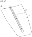
- FIG. 8C shows an overview of the cargo door rails
- FIG. 8D shows a perspective view of the location housing of FIG. 8B in a connected state
- FIG. 8E shows details of the cargo door rail
- FIG. 8F shows details of the cargo door rail
- FIG. 9 shows the rail AFT geometry (at the end of the cargo door rails) in the aerial delivery area
- FIG. 10A shows a CME stow mechanism
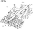
- FIG. 10B shows another perspective view of the CME and its festoon
- FIG. 10C shows a case when the CME is not properly latched for stowage
- FIG. 10D shows a case when the CME unable to be safely stowed due to interference visual indication, and a case when the CME stowage device properly latched and the CME can be properly stowed;
- FIG. 11A shows an example of a torque and speed control
- FIG. 11B shows a speed profiling in relation to FIG. 11A ;
- FIG. 12 shows a perspective view of the festoon cable assembly and rounds
- FIG. 13A shows a side view of a disconnected/connected state of a rail actuator
- FIG. 13B shows a side view of proximity switches in relation the rails
- FIG. 14 shows a method embodiment which also reflects the interaction between the components of the device embodiment.
- the present disclosure describes the design and implementation of a mono-rail crane system 10 of the A400M aircraft (as an embodiment of the general aircraft). Further, the present disclosure describes the architecture of the system and identifies the components that make up the system.
- the content includes:
- the present disclosure is applicable to an aircraft (such as the A400M aircraft) equipped with the crane system of the present disclosure.
- the mono-rail crane system 10 is comprised of the following main components:
- a first longitudinal rail 100 installed on the underside of the rear cargo door D.
- a rail shall enable crane stowage so as not to protrude into the cargo hold envelope.
- This inner rail assembly includes also an actuated device 400 to configure the demanded position of the rail 200 .
- the following devices are preferably used for the control of the crane 10 and for the control of the connection of the rails 100 , 200 , respectively:
- a hand held remote control (Remote Control Unit). This may be part of the Load Master Control System.
- a control panel to operate and control movement of the inner rail 200 to the outer rail 100 (Rails Actuator 400 Control Panel).
- the crane system 10 is designed to be capable of lifting loads of up to 5,000 kg from the ground, a truck or transport device onto the ramp.
- the main drivers for the crane development preferably are:
- the fix structure (rail assemblies): will be designed according to the structural safe considerations criteria.
- the FHA will define the DAL allocation of the system.
- the frame plan of the airplane 1 (embodied as an A400M) is given in FIG. 1E .
- the installation of the crane system 10 is preferably focused on the rear part of the aircraft/airplane 1 , that is, in ramp hold and cargo door D, along the aircraft center x-datum, allowing the longitudinal movement of the mobile parts as is shown in FIG. 1D .
- the cargo hold rail 200 assembly is installed between FR 60 (frame 60 ) and FR 63 (frame 63 ) to be explained herein below.
- the overview can be seen in FIG. 2A .
- the cargo door rail 100 preferably is an installed rail assembly located in the underside of the cargo door D, e.g., from frame 63 to frame 72 to be described herein below.
- the external rail 10 is preferably divided into four (4) tracks (this does not preclude a different number of tracks).
- Each track is preferably mounted on slide brackets, which are attached to the interface fittings.
- These interface fittings are preferably attached to the cargo door D in already existing IF holes.
- the Crane Mobile Equipment, CME, 300 is preferably located in the Rear Fuselage Area.
- the CME 300 preferably has the capability to move along the complete rail assemblies 100 , 200 , from FR 60 up to FR 72 (frame 72 ) to be explained herein below.
- the CME 300 preferably has means to be blocked at the end of crane rail cargo hold (as an example of the mono-rail 200 ) which is the stowage position (between FR 60 and FR 63 ). In this stowage position, the CME 300 is not allowed to move or to perform any operation or command.
- the CME 300 is preferably unblocked from its stowage position and it is able to move from its stowage position to the rear end of the cargo door rail 100 , when both rails 100 , 200 are connected.
- the equipment When the equipment is in this operation mode, it can move from FR 60 to FR 72 approximately.
- a festoon cable and its support structure in stowage position are preferably located attached to the cargo hold rail 200 , between frame 59 and frame 60 approximately.
- the wiring preferably transmits the commands from LMWS/RCU/RACP to the CME 300 , enabling it to travel from its stowage position to the rear part of the cargo door rail.
- the (linear) rail actuator 400 once installed, preferably is a part of the cargo hold rail assembly, acting as an additional rod of the structure.
- the rail actuator 400 is preferably located close to the attachments of the rear part of the cargo door rail between FR 62 and FR 63 approximately.
- the commands of the rail actuator 400 are preferably sent to the actuator 400 and the CME 300 after the proximity sensors have been taken into account for actuator operation logics. Their goal is to assure proper connection between rails being located at the rear end of the cargo hold rail 200 (preferably interfacing with the sensing limits installed at the door rail when connecting rails).
- a RACP Rotary Actuator Control Panel
- the wiring associated with the actuator and with the panel is preferably installed between the ceiling area and the left side fuselage, frames 59 - 63 .
- the Crane control panel is preferably included in the LMCP, which is located in the rear part of the cargo hold on the LH side aft of the paratroop door.
- the two RCUs are preferably equipped with flexible cable of adequate length, and they are also used for other cargo handling purposes.
- Six connection plugs are preferably distributed within the cargo hold in order to use the RCUs at various locations (4 on the left-hand side, 2 on the right-hand side).
- the mechanical architecture is as shown in FIG. 5 .
- the system is divided into two major assemblies that interface with different parts of the aircraft 1 : the inner rail assembly 200 and the outer rail assembly 100 .
- the inner rail assembly 200 is the structure attached to the Cargo Hold frames 60 and 63 , and it is permanently stowed during flight. This stowage is reverted when the CCS is required to operate, as explained below.
- the outer rail assembly 100 is the structure attached to the underpart of the cargo door D. It is preferably composed by a set of tracks (e.g., x4) that are linked between them in order to enable thermal effects to occur without having impact on the installation of the crane system 10 . These tracks are preferably supported by the mounting brackets, (e.g., x5), which have capacity to withstand forces in the “Y” and “Z” axis. Preferably, only the AFT mounting bracket has the capability to withstand forces in the “X” (longitudinal) direction.
- the actuator 400 is the part of the system responsible for the configuration of the rail assemblies 100 , 200 . During flight, it is preferably retracted in order to enable movement of the cargo door D and aerial delivery operations to be performed. When on ground, with the crane system 10 being operative, the actuator 400 is preferably extended to enable the rails assemblies (inner 200 and outer 200 ) to link (i.e., alignment performed by the alignment device and the locator).
- the Rails Actuation Control Panel is preferably located between FR 59 and FR 60 , LH of the aircraft 1 .
- the panel is responsible for commanding the actuator 400 .
- the aircraft 1 supplies the CCS preferably with 3 types of electrics:
- DC power is preferably also used for control purposes (actuator power control logics, implemented at system level).
- the main source of power preferably is the aircraft generating & distribution system from PEPDC and SEPDC and through the associated RCCB's.
- the main source of control signals preferably is the LMWS, which hosts the hierarchy of command (both LMCP and RCU can command the CME).
- the CCS preferably also feeds the LMWS with failure signals that, when launched, trigger different alerts and indications at LMWS level.
- This alert/indication logics is preferably also hosted in the LMWS.
- the CCS preferably is a BITE contributor and therefore the BITE shall be defined with the above shown signals.
- the requirements of the crane system 10 can be divided into the following categories:
- Cargo hold rail 200 structure
- Cargo door rail 100 structure is:
- the cargo hold rail 200 assembly is preferably composed by two subtypes of components, according to its functionality:
- the rail 200 there preferably are elements which are used for structural supporting of the system (Structural load paths, actuator for rails configuration, alignment devices, etc.) and also for supporting of the electrical elements which will be installed (harnesses, sensors, etc.).
- This alignment device part is preferably located below the rail and has the goal of configuring the two rails to have a proper operation.
- the rails preferably are configured by means of the rails actuator 400 (see following chapters).
- the logics for activation of the crane system 10 , power supply and cargo hold rail configuration are allocated in the LMWS. These logics consider several parameters prior to CCS activation, such as:
- the rails 100 , 200 are preferably configured into operational/stowage positions by means of the rails actuator 400 , which is addressed in further chapters.
- the cargo hold rail 200 preferably allows the longitudinal movement of the CME 300 by means of the wheels installed on the CME 300 .
- the cargo hold rail 200 Assembly provides preferably supports to maintain the CME 300 in stowed position when the CME is not being used and always for flight conditions.
- the assembly is preferably composed by the inner rail 200 , the structural supporting components and their attachments to the aircraft 1 interfaces.
- This cargo hold rail assembly preferably is configured (by being moved FWD or AFT) for operation or flight. This configuration is preferably performed by means of the actuator extension and retraction respectively.
- the cargo hold rail 200 assembly preferably has a locator device male pin to ensure alignment between both rails during operation.
- the structure of cargo hold rail 200 assembly preferably includes:
- the cargo hold rail 200 and the Cargo Door Rail 100 are preferably connected by means of a junction device that allows the transition of the CME between the two rails.
- the cargo door rail 100 assembly is responsible for transfer of loads L from equipment to aircraft 1 .
- the rail 100 is preferably permanently attached to the cargo door D.
- At the AFT end of the rail 100 there are preferably two bumpers (one on each side) whose mission is to disable further movement of the CME 300 .
- the cargo door rail 100 assembly preferably has also a locator housing (female, located in the FWD end side) which is acting as a guidance for the male alignment device (located in the lower flange of the cargo hold rail 200 ) AFT movement during configuration for operation.
- the cargo door rail 100 assembly preferably has structural purposes only. There preferably are no harnesses or cables mounted on this cargo door rail 100 assembly.
- the cargo door rail 100 allows the longitudinal movement of the CME 300 .
- This cargo door rail 100 preferably supports the CME 300 during the operation to ensure the functions of hoisting, lowering and transfer of loads.
- the cargo door rail 100 is split preferably in four parts and installed on the underside of the cargo door D by means of e.g., 5 attachment points.
- the structure of the cargo door rail 100 assembly preferably includes:
- Equipment structure and wheel interfaces with rail 100 , 200 .
- the unit is preferably stowed at the cargo hold rail 200 and secured with two independent mechanical devices to the rail to prevent any movement during flight.
- Each one of these two devices which are equal one to another, preferably has the capability of maintaining the CME 300 position during flight mode.
- these stowage devices shall be manually disconnected.
- the hook is preferably also protected from any movement with a mechanical stowage device.
- the crane mobile equipment is preferably electrically driven to perform hoisting, lowering and transferring of loads.
- the CME 300 preferably has also a mechanical backup to enable the operator to perform a manual operation (for hoisting, lowering and travelling), with a crank from the aircraft EPES system (EPES crank is part of the CSA), in case of electrical power loss/failure.
- EPES crank is part of the CSA
- the CME 300 preferably incorporates wheel mechanisms (e.g., buggy trains x2, wheels x4 mounted on each bogey) to cope with the displacement of the equipment along both rails 100 , 200 .
- the wheel mechanism preferably provides a smooth transition while passing through the x-gap between both rails.
- a set of lateral rollers preferably supports the lateral load and provides an alignment along the longitudinal axis of the aircraft restraining z-axis moment of the CME 300 .
- the lateral wheels preferably support the resultant dynamic lateral forces from the cable-hook lateral movement, with a maximum of 10° inclination and the lateral friction forces.
- the equipment preferably has features for load transfer to control position and speed. This position and speed are preferably controlled via the ECU of the CME (HW and SW control).
- a weight display is preferably installed in the CME at 33° ( ⁇ 3°) approximately in order to show to the load master LM the actual weight of the load L thus avoiding any overweight in the equipment.
- the CME 300 preferably has features for load lifting including a power brake, speed limitation and stroke limitation:
- the power brake is normally activated unless there is a hoist command (either UP or DOWN).
- the speed limitation is performed via the CME ECU (SW control).
- the components for hoist function preferably include at a minimum the drum drive, cable drum assembly and hook attached to the cable end.
- the hook latch is preferably unlatched or released by the operator.
- an overload protection mechanism is preferably included by means of a set of electronic weight sensors providing weight measurement to the Control Unit. This weight is also displayed in the ECU weight display.
- a controller of the logic of operation and a power supply module for power conversion and rectification is preferably also part of the equipment.
- the CME 300 preferably performs power conversion to accommodate e.g. a 115 VAC WF three-phase power supply into a 270 VDC power supply for the motors.
- the electrical controller preferably implements the necessary logics for the control of the crane 10 .
- the logics of operation are preferably implemented according to the commands transmitted from the LMC.
- a +28 VDC command input is preferably also provided from the RACP to the CME to enable control logics and ECU power supply.
- the CME 300 preferably has means to minimize lateral forces and torque transmitted to the rail. This is achieved by designing an attaching device which is able to move in the Y-direction. This device preferably physically displaces the arresting point between the CME 300 and the pallet, aligning the pallet lifting force line and the torsion center of the beam, minimizing the distance between them and therefore the torsion moment.
- the CME 300 preferably embeds SW to perform logics of control.
- the functions that this SW shall perform preferably are:
- the SW of the CME is preferably only operated on ground.
- the CME 300 preferably is to be sufficiently blocked during flight mode so as to ensure proper, safe operation of the CSA.
- two independent stowage devices preferably are located in the underside part of the cargo hold rail 200 (e.g., below the lower flange). These two devices located below the rail Inner Rail Structure belong to the inner rail 200 structure and act as female housings for male structural pins to be interlocked from the CME 300 .
- the CME 300 preferably has the two correspondent male pins whose goal is to ensure total restriction of movement while the CME is in flight or in any other mode which is not the operative mode.
- these two devices preferably are similar one to another, but totally independent and also composed by structural elements. No electronics needs to be allocated in this function. Further, the two devices need visual confirmation of positive locking of the male pin into the female device which it is matching.
- the detection means of the CME will be visual. For this purpose, the detection means will only be indicating the proper attitude when the stowage device is properly inserted into its applicable housing.
- the stowage devices preferably are also actuated by means of the EPES crank.
- the lifting function is preferably performed by means of:
- the lifting function is preferably controlled by the ECU, which is monitoring motor characteristics such as turning speed, readings of the weight sensors, etc.
- the weight sensors When a pallet is being loaded/unloaded, the weight sensors preferably perform readings of the weight in the cable. This reading feeds the ECU with the weight which is suspended.
- the ECU preferably has then the ability to compensate the force of the cable with torque in the motor. When those are compensated, then the fail-safe brake is disengaged and the motor starts controlling the acceleration and speed of the suspended mass.
- the logics preferably are the same that for the “hoist up” command For each command requested, it is possible to perform it in two speeds: Fast and Slow.
- a restricted hoisting function is preferably available when one phase from the Power Supply converted in the Power Supply Unit (PSU) is lost. In this case, the CME 300 would be able to lift 3.3 tons approximately.
- the fleet angle is the maximum angle that the CME 300 is able to see in relation to the vertical.
- the CCS has included several means for detection these angles. This function is preferably allocated inside the CME 300 .
- the fleet angle indications delivered by the CME preferably are:
- a signal is preferably sent to the ECU that then declares the applicable caution signal.
- a signal is preferably sent to the ECU and the applicable warning signal is triggered.
- the traverse movement function enables the CME 300 to move the loads L from outside to inside the aircraft 1 or vice versa. This function is preferably performed by means of:
- the traverse movement is preferably also fed with logics given by switches located in the rail area surroundings. They have the goal of enabling smooth speed transitions/changes, especially for the case of the rail end stops.
- the ECU preferably sets automatic deceleration when reaching the pre-deceleration switch, located mainly in the surroundings of the rail ends.
- the traverse actuator preferably has, as the hoist actuator, a fail-safe brake. In case of absence of power or command, the brakes are applied and movement is not permitted.
- the weight may be requested to be shown in the ECU display. This weight is preferably measured by means of two dual weight sensors located in the attachment between the Hoist Actuator and the Frame Carriage.
- These dual weight sensor cells preferably provide an output which is read by the ECU and converted into a display message.
- the weight is preferably indicated with two digits, in the form of metric tons.
- the CME 300 Whenever the CME 300 fails, it preferably declares a fail to the LMWS. This fail can be either permanent or temporary; and depending on this it will be triggered an operational failure or a system failure. The failures preferably are displayed in the LMWS.
- the CME ECU display has preferably the capability of displaying several internal errors. These errors will be detailed in the supportability and maintainability documentation.
- the festoon cable preferably travels aft and forward with CME 300 without interfering with CME operation.
- the cable trucks preferably are integrated with the rail design to slide the cable together with the CME.
- the festoon cable preferably allows a longitudinal travel of the CME 300 of 6400 mm approximately.
- the rest of the wiring preferably is guided by the airframe and the cargo hold rail 200 frame without disturbing the crane system 10 or any other systems.
- the rail actuator 400 is actuated to align and connect the cargo hold rail 200 and cargo door rail 100 , and once connected, it actuates as a structural bar of the cargo hold rail 200 assembly.
- the rail actuator 400 can be operated either electrically or manually. For that purpose, there is preferably installed a manual back-up to allow the operation with a crank from the floor of the aircraft 1 .
- the function of the rail actuator 400 is to move the cargo hold rail 200 assembly until it results mechanically linked to the cargo door rail 100 (the actuator 400 is not responsible for alignment between both assemblies, as this is an alignment device responsibility).
- FIG. 13A shows the kinematics of connected/disconnected rails.
- the actuator 400 is preferably controlled externally by the RACP that is responsible for actuator commands and indication outputs from the actuator.
- This rails connection panel preferably includes a switch to command the actuator, as well as indicators for the status coming from the proximity switches and the actuator.
- the entire panel is preferably covered by a safety guard that prevents undesired movement from occurring.
- proximity switches are preferably fixed to the rear end of the cargo hold rail 200 and they make contact with the RWD Interface Bracket of the cargo door D when both rails are connected.
- the switches preferably implement logics to prevent the actuator to continue its movement when the inner rail is close to the outer rail.
- the proximity switches When these proximity switches are pushed (e.g., because the inner rail 200 structure has gone too close to the outer rail 100 ), then the proximity switches preferably remove the power from the “EXTEND” command of the actuator 400 . However, the “RETRACT” command remains unchanged from the proximity switches point of view, since the retraction command has a direct wire between the RACP and the actuator.
- the proximity switches are preferably responsible for providing a signal that will enable the “Rails Ready for Operation” indication to be lit.
- the crane panel in the LMCP as well as hand held remote control unit preferably include the following controls:
- the LMCP and the Remote Control Units enable the operation of the crane system 10 by just one operator.
- the crane 10 is preferably operated on ground only for loading and offloading. Further, the crane system 10 preferably provides electrical status indication on the LMWS for:
- CME 300 power on status (shown on RCU and LMCP)
- the crane system 10 preferably is provided in order to enable autonomous loading and offloading of loads once integrated with the rails.
- the CME 300 preferably is capable of operating at different speeds of hoisting and transferring.
- the crane 10 is preferably designed in order to operate on a sloped cargo door D of 3.5° (downwards outside) nominal. Further, the crane system 10 preferably provides electrical status indication on the LMWS for:
- the rail operation for extension is issued from the RACP.
- the LM can release the CME's stows and hook's stow and select “Crane” from the RCU to begin the mission.
- the CME preferably has a weight display in order to control the loaded weight.
- the LM is able to hoist and carry the load L to the ramp. If the load is below 2000 kg, then the LM can carry it inside the aircraft 1 .
- the LM is preferably able to hoist it from the ramp and carry it out. Below 2000 kg the LM can carry it from inside the aircraft.
- a manual back up is preferably available to be operated with a crank, in case needed due to, e.g., absence of power.
- the provisions for growth capabilities in terms of hardware and interfaces are at least 5 spare connector pins and spare conductors in the wiring interface if possible. If not possible, at least 10-15% of spare pins connections are provided.
- the crane rail structures 100 , 200 preferably are attached to the ceiling and to the cargo door D.
- the installation concept for the crane system 10 includes interfacing of mechanical and electrical interfaces to the aircraft structure and the aircraft electrical system.
- five interface points are provided on the underside of the cargo door D for attaching the I/F Brackets to grab the door rail 100 .
- four interface areas are preferably provided on the ceiling of the aircraft 1 (e.g., two at frame 60 and two at frame 63 ) to support the cargo hold rail 200 Structure.
- the electrical interface is preferably composed by the LMCP commands discretes and the power input from ATA24.
- the wiring shall be routed without causing interferences (mechanic or electromagnetic) as per normal designs and directives. System interface, installation, and tolerance drawings and documents will be referenced to attain a better installation concept.
- All parts involved preferably are preassembled to the highest assembly level possible to facilitate installation on the aircraft.
- All parts of the system preferably are designed to minimize impact of installation tolerances, and to ease the mounting without downgrading system performance.
- the crane system 10 preferably interfaces with the following systems or aircraft parts:
- E Electrical Interface (power supply, . . . )
- MMI Man Machine Interface (switch, . . . )
- the crane components are provided with the following provisions for interface:
- the CME 300 (including controller) preferably has:
- the cargo door rail 100 assembly preferably has:
- the cargo hold rail 200 assembly preferably has:
- the wiring harness preferably has:
- Manual Drive Interface preferably has:
- the crane system 10 preferably interfaces with the LMC via LMWS, providing the status of the crane system 10 .
- the Crane BITE function hosted on LMC preferably records the status provided by the crane, and also the status of the related ATA24 interfaces as well as inputs for the logics of operation.
- Loading/offloading with crane 10 defined procedures must be followed to assure a safe operation. Proper checks, appropriate operation sequence, limitations compliance, and stowage instructions must be accomplished.
- General loading procedure (considering toes usage. If not necessary, the toes step can be removed) preferably comprises:
- the aircraft is actuated in order to reach a correct attitude for loading/unloading operation (kneeling+struts and toes deployment).
- ramp toes can be easily used on prepared and compacted fields, but shoring activities could be needed in non-prepared fields. Also shoring tasks can be needed for stabilizer struts in non-prepared fields.
- shoring tasks can be needed for stabilizer struts in non-prepared fields.
- the pallet/bulk load must be placed inside the lifting envelope of the hook and below the cargo door (or truck aligned/perpendicular to the longitudinal x-axis of the aircraft). This is responsibility of the ground operator.
- Inner rail structure actuation is performed to assure continuity between supporting structures.
- the hook is lowered and attached to the pallet/load. At this moment, before lifting the load, the operator must check that the fleet angle of the hoist is not above the allowed angle (if it is not inside the envelope allowed, take corrective actions). Then the load is lifted by the mobile equipment until the necessary height is achieved (until the pallet clears the cargo ramp floor). Terminal phases of the lifting (taking off and arrival to the highest height, must be carried out at low hoisting speed).
- the mobile equipment is commanded FWD until the load is above the deployment point (cargo ramp/cargo ramp toes).
- the load is then lowered and placed between the ramp toes and the cargo ramp.
- the hook is de-attached and lifted again. Then, the mobile equipment can be either moved to the stowage position if the loading process has been finished, or moved to the loading initial position again if the loading operation has to be continued.
- the operator commands the CME to the stowage position, the cargo hold structure to retract position, and then the system is powered off Toes struts, ramp toes, and ramp and cargo door are configured to the initial positions.
- Unloading process is analog to the loading operation.
- the load must be located on the toes previously to be lifted by the crane (not necessary for loads lighter than 2000 kg).
- the crane 10 preferably must ensure operation on a sloped Cargo Door) (3.5°). Considering the tolerances (+/ ⁇ 2.0°), operation must be assured between 1.5° and 5.5°.
- the crane 10 preferably ensures hoisting and transferring operation of loads up to 5,000 kg.
- the CCS preferably is able to pick loads L from/to a truck whose bed height is between 0.8 and 1.7 meters.
- the CME preferably is capable of operating at different speeds:
- the hoisting speeds will be 4 m/min and 0.6 m/min.
- the transfer speeds will be 18 m/min and 3 m/min.
Landscapes
- Engineering & Computer Science (AREA)
- Aviation & Aerospace Engineering (AREA)
- Mechanical Engineering (AREA)
- Carriers, Traveling Bodies, And Overhead Traveling Cranes (AREA)
- Control And Safety Of Cranes (AREA)
Applications Claiming Priority (3)
| Application Number | Priority Date | Filing Date | Title |
|---|---|---|---|
| EP16380027.9 | 2016-06-07 | ||
| EP16380027.9A EP3254952B1 (de) | 2016-06-07 | 2016-06-07 | Einschienenkransystem in einem flugzeug |
| EP16380027 | 2016-06-07 |
Publications (2)
| Publication Number | Publication Date |
|---|---|
| US20170349263A1 US20170349263A1 (en) | 2017-12-07 |
| US10604229B2 true US10604229B2 (en) | 2020-03-31 |
Family
ID=56413608
Family Applications (1)
| Application Number | Title | Priority Date | Filing Date |
|---|---|---|---|
| US15/615,083 Active 2038-10-11 US10604229B2 (en) | 2016-06-07 | 2017-06-06 | Mono-rail crane system in an aircraft |
Country Status (3)
| Country | Link |
|---|---|
| US (1) | US10604229B2 (de) |
| EP (1) | EP3254952B1 (de) |
| CN (1) | CN107571999B (de) |
Cited By (1)
| Publication number | Priority date | Publication date | Assignee | Title |
|---|---|---|---|---|
| WO2022221751A1 (en) * | 2021-04-16 | 2022-10-20 | Breeze-Eastern Llc | Implementing an emergency stopping break for hoist systems |
Families Citing this family (8)
| Publication number | Priority date | Publication date | Assignee | Title |
|---|---|---|---|---|
| US10703471B2 (en) | 2016-06-03 | 2020-07-07 | Bell Helicopter Textron Inc. | Anti-torque control using matrix of fixed blade pitch motor modules |
| US10526085B2 (en) | 2016-06-03 | 2020-01-07 | Bell Textron Inc. | Electric distributed propulsion anti-torque redundant power and control system |
| US10589969B2 (en) * | 2018-04-25 | 2020-03-17 | Rinaldo Brutoco | System, method and apparatus for widespread commercialization of hydrogen as a carbon-free alternative fuel source |
| US20210163126A1 (en) * | 2018-04-30 | 2021-06-03 | Avidrone Aerospace Incorporated | Modular unmanned automated tandem rotor aircraft |
| EP4025493A4 (de) * | 2019-09-05 | 2023-08-30 | ZSM Holdings LLC | Flugzeugrumpfkonfigurationen, die einen heckaufprall vermeiden und gleichzeitig lange nutzlasten ermöglichen |
| EP3838753B1 (de) * | 2019-12-17 | 2022-03-16 | LEONARDO S.p.A. | Wandelflugzeug |
| GB2618700B (en) * | 2020-08-27 | 2024-03-20 | Borealis Tech Ltd | Airport freight and cargo transfer system |
| BR112023018205A2 (pt) * | 2021-03-10 | 2023-12-05 | Zsm Holdings Llc | Sistemas e métodos para montagem de grande carga e carregamento da mesma em uma aeronave de carga |
Citations (9)
| Publication number | Priority date | Publication date | Assignee | Title |
|---|---|---|---|---|
| US3051419A (en) * | 1959-08-10 | 1962-08-28 | Boeing Co | Overhead cargo handling mechanism for swing-tail airplanes |
| US3371891A (en) | 1965-09-16 | 1968-03-05 | Lockheed Aircraft Corp | Loading, conveying and ejecting mechanism for aircraft |
| US3463334A (en) * | 1967-04-17 | 1969-08-26 | Boeing Co | Cargo loading apparatus |
| US3552587A (en) * | 1968-04-16 | 1971-01-05 | Mc Donnell Douglas Corp | Powered hoist-baggage container handling system |
| US3561704A (en) * | 1967-07-14 | 1971-02-09 | Carsten Schulze | Arrangement of the openings to loading compartments in vertical take off and landing air vehicles |
| US3952974A (en) * | 1974-12-20 | 1976-04-27 | The Boeing Company | Cargo-handling system for standard body airplanes |
| EP0294278A1 (de) | 1987-06-04 | 1988-12-07 | AEROSPATIALE Société Nationale Industrielle | Unabhängige Aufladevorrichtung für Transportflugzeuge |
| US5647577A (en) * | 1994-07-07 | 1997-07-15 | Feldman; Yakov Z. | Brake apparatus for an extendable lift apparatus |
| US5908279A (en) * | 1997-08-12 | 1999-06-01 | Mote; Preston P. | Motorized trailer for delivery and installation of propane tanks |
Family Cites Families (4)
| Publication number | Priority date | Publication date | Assignee | Title |
|---|---|---|---|---|
| DE19707519B4 (de) * | 1997-02-25 | 2007-11-08 | Scandinavian Bellyloading Co.Ab | Einrichtung zum Beladen eines Laderaums insbesondere eines Flugzeuges mit Stückgut |
| US7270297B2 (en) * | 2004-01-30 | 2007-09-18 | The Boeing Company | Hoist for aircraft cabin construction |
| US8490923B2 (en) * | 2009-12-22 | 2013-07-23 | Embraer S.A. | Portable onboard vehicular hoist systems |
| US8864079B2 (en) * | 2012-10-08 | 2014-10-21 | The Boeing Company | Aircraft cargo compartment container crane system |
-
2016
- 2016-06-07 EP EP16380027.9A patent/EP3254952B1/de active Active
-
2017
- 2017-06-06 CN CN201710438550.5A patent/CN107571999B/zh active Active
- 2017-06-06 US US15/615,083 patent/US10604229B2/en active Active
Patent Citations (11)
| Publication number | Priority date | Publication date | Assignee | Title |
|---|---|---|---|---|
| US3051419A (en) * | 1959-08-10 | 1962-08-28 | Boeing Co | Overhead cargo handling mechanism for swing-tail airplanes |
| US3371891A (en) | 1965-09-16 | 1968-03-05 | Lockheed Aircraft Corp | Loading, conveying and ejecting mechanism for aircraft |
| US3463334A (en) * | 1967-04-17 | 1969-08-26 | Boeing Co | Cargo loading apparatus |
| US3561704A (en) * | 1967-07-14 | 1971-02-09 | Carsten Schulze | Arrangement of the openings to loading compartments in vertical take off and landing air vehicles |
| GB1228469A (de) | 1967-07-14 | 1971-04-15 | ||
| US3552587A (en) * | 1968-04-16 | 1971-01-05 | Mc Donnell Douglas Corp | Powered hoist-baggage container handling system |
| US3952974A (en) * | 1974-12-20 | 1976-04-27 | The Boeing Company | Cargo-handling system for standard body airplanes |
| EP0294278A1 (de) | 1987-06-04 | 1988-12-07 | AEROSPATIALE Société Nationale Industrielle | Unabhängige Aufladevorrichtung für Transportflugzeuge |
| US4858855A (en) * | 1987-06-04 | 1989-08-22 | Aerospatiale Societe Nationale Industrielle | Autonomous onboard loading device for a cargo-aircraft |
| US5647577A (en) * | 1994-07-07 | 1997-07-15 | Feldman; Yakov Z. | Brake apparatus for an extendable lift apparatus |
| US5908279A (en) * | 1997-08-12 | 1999-06-01 | Mote; Preston P. | Motorized trailer for delivery and installation of propane tanks |
Non-Patent Citations (1)
| Title |
|---|
| European Search Report, dated Nov. 8, 2016, priority document. |
Cited By (1)
| Publication number | Priority date | Publication date | Assignee | Title |
|---|---|---|---|---|
| WO2022221751A1 (en) * | 2021-04-16 | 2022-10-20 | Breeze-Eastern Llc | Implementing an emergency stopping break for hoist systems |
Also Published As
| Publication number | Publication date |
|---|---|
| CN107571999B (zh) | 2020-03-24 |
| EP3254952B1 (de) | 2018-09-26 |
| CN107571999A (zh) | 2018-01-12 |
| US20170349263A1 (en) | 2017-12-07 |
| EP3254952A1 (de) | 2017-12-13 |
Similar Documents
| Publication | Publication Date | Title |
|---|---|---|
| US10604229B2 (en) | Mono-rail crane system in an aircraft | |
| US9663228B2 (en) | Automated sling load handler for an aircraft | |
| US11565801B2 (en) | Aerial transportation system | |
| US8788085B2 (en) | Fully automated cargo loading system | |
| US10202065B2 (en) | System for moving loads comprising a locking arrangement that is operable by means of a transport vehicle | |
| US8408861B2 (en) | Cargo container handling system and associated method | |
| JP6987605B2 (ja) | 貨物処理システム及び方法 | |
| JP5886863B2 (ja) | コンテナ積み替えシステム | |
| US9238504B2 (en) | Cargo hold floor for a cargo hold of an aircraft, function element for installing in a cargo hold floor, side guide, fixing device for introducing a tensile load, and device for ejecting freight items | |
| CN111003147B (zh) | 一种飞机机翼折叠控制方法 | |
| CN103879542A (zh) | 带有改进的起落架舱的飞行器机头 | |
| EP3931656B1 (de) | Unbemanntes bodenbasiertes transportfahrzeug und verfahren zum transportieren von gegenständen | |
| CN106395568A (zh) | 电梯恢复轿厢 | |
| JP5961844B2 (ja) | 搬送作業システム | |
| WO2019135791A2 (en) | Vertical takeoff and landing transportation system | |
| JP2010247931A (ja) | 自動倉庫システム | |
| WO2018160346A1 (en) | System and method for indexing vehicles of a vehicle system | |
| US20050253021A1 (en) | Operational ground support system | |
| US7631837B2 (en) | Electrical interlock and indication system for aircraft | |
| US20230009616A1 (en) | Retractable cargo hook | |
| KR102383849B1 (ko) | 이동식 강체전차선 시스템 | |
| US20240010472A1 (en) | Double-locking hooking system intended for transporting a load outside an aircraft | |
| KR102391968B1 (ko) | 이동식 강체전차선 시스템 | |
| CN116161442A (zh) | 自动化搬运系统及其工作方法 | |
| WO2023062622A1 (en) | Aircraft |
Legal Events
| Date | Code | Title | Description |
|---|---|---|---|
| STPP | Information on status: patent application and granting procedure in general |
Free format text: DOCKETED NEW CASE - READY FOR EXAMINATION |
|
| AS | Assignment |
Owner name: AIRBUS DEFENCE AND SPACE GMBH, GERMANY Free format text: ASSIGNMENT OF ASSIGNORS INTEREST;ASSIGNORS:LOPEZ, ANA RUBIO;ARIAS, DANIEL LLANES;MARTINEZ, OSCAR;AND OTHERS;SIGNING DATES FROM 20170518 TO 20170523;REEL/FRAME:049052/0279 Owner name: AIRBUS DEFENCE AND SPACE S.A., SPAIN Free format text: ASSIGNMENT OF ASSIGNORS INTEREST;ASSIGNORS:LOPEZ, ANA RUBIO;ARIAS, DANIEL LLANES;MARTINEZ, OSCAR;AND OTHERS;SIGNING DATES FROM 20170518 TO 20170523;REEL/FRAME:049052/0279 |
|
| STPP | Information on status: patent application and granting procedure in general |
Free format text: NOTICE OF ALLOWANCE MAILED -- APPLICATION RECEIVED IN OFFICE OF PUBLICATIONS |
|
| STPP | Information on status: patent application and granting procedure in general |
Free format text: PUBLICATIONS -- ISSUE FEE PAYMENT RECEIVED |
|
| STPP | Information on status: patent application and granting procedure in general |
Free format text: PUBLICATIONS -- ISSUE FEE PAYMENT VERIFIED |
|
| STCF | Information on status: patent grant |
Free format text: PATENTED CASE |
|
| MAFP | Maintenance fee payment |
Free format text: PAYMENT OF MAINTENANCE FEE, 4TH YEAR, LARGE ENTITY (ORIGINAL EVENT CODE: M1551); ENTITY STATUS OF PATENT OWNER: LARGE ENTITY Year of fee payment: 4 |