US10596801B2 - Three-dimensional printing apparatus and inkjet coloring method thereof - Google Patents
Three-dimensional printing apparatus and inkjet coloring method thereof Download PDFInfo
- Publication number
- US10596801B2 US10596801B2 US15/458,980 US201715458980A US10596801B2 US 10596801 B2 US10596801 B2 US 10596801B2 US 201715458980 A US201715458980 A US 201715458980A US 10596801 B2 US10596801 B2 US 10596801B2
- Authority
- US
- United States
- Prior art keywords
- layer
- ink
- discharge volume
- controller
- ink discharge
- Prior art date
- Legal status (The legal status is an assumption and is not a legal conclusion. Google has not performed a legal analysis and makes no representation as to the accuracy of the status listed.)
- Expired - Fee Related, expires
Links
- 238000000034 method Methods 0.000 title claims abstract description 25
- 238000004040 coloring Methods 0.000 title claims abstract description 16
- 238000010146 3D printing Methods 0.000 title claims abstract 4
- 238000007639 printing Methods 0.000 claims abstract description 82
- 239000004566 building material Substances 0.000 claims abstract description 23
- 239000003086 colorant Substances 0.000 claims description 17
- 239000000463 material Substances 0.000 claims description 14
- 239000000155 melt Substances 0.000 claims description 5
- 230000008018 melting Effects 0.000 claims description 3
- 238000002844 melting Methods 0.000 claims description 3
- 238000010586 diagram Methods 0.000 description 10
- 238000004519 manufacturing process Methods 0.000 description 6
- 238000005516 engineering process Methods 0.000 description 5
- 238000011960 computer-aided design Methods 0.000 description 4
- 239000007921 spray Substances 0.000 description 4
- 238000012360 testing method Methods 0.000 description 4
- 238000012545 processing Methods 0.000 description 3
- 229920000122 acrylonitrile butadiene styrene Polymers 0.000 description 2
- 230000008901 benefit Effects 0.000 description 2
- 230000000694 effects Effects 0.000 description 2
- 238000001125 extrusion Methods 0.000 description 2
- 239000004626 polylactic acid Substances 0.000 description 2
- 239000004676 acrylonitrile butadiene styrene Substances 0.000 description 1
- 239000000654 additive Substances 0.000 description 1
- 230000000996 additive effect Effects 0.000 description 1
- 230000008021 deposition Effects 0.000 description 1
- 238000013461 design Methods 0.000 description 1
- 239000000975 dye Substances 0.000 description 1
- 238000002474 experimental method Methods 0.000 description 1
- 238000012986 modification Methods 0.000 description 1
- 230000004048 modification Effects 0.000 description 1
- 229920000747 poly(lactic acid) Polymers 0.000 description 1
- 238000009877 rendering Methods 0.000 description 1
- 238000005507 spraying Methods 0.000 description 1
Images


Classifications
-
- B—PERFORMING OPERATIONS; TRANSPORTING
- B29—WORKING OF PLASTICS; WORKING OF SUBSTANCES IN A PLASTIC STATE IN GENERAL
- B29C—SHAPING OR JOINING OF PLASTICS; SHAPING OF MATERIAL IN A PLASTIC STATE, NOT OTHERWISE PROVIDED FOR; AFTER-TREATMENT OF THE SHAPED PRODUCTS, e.g. REPAIRING
- B29C64/00—Additive manufacturing, i.e. manufacturing of three-dimensional [3D] objects by additive deposition, additive agglomeration or additive layering, e.g. by 3D printing, stereolithography or selective laser sintering
- B29C64/10—Processes of additive manufacturing
- B29C64/106—Processes of additive manufacturing using only liquids or viscous materials, e.g. depositing a continuous bead of viscous material
- B29C64/118—Processes of additive manufacturing using only liquids or viscous materials, e.g. depositing a continuous bead of viscous material using filamentary material being melted, e.g. fused deposition modelling [FDM]
-
- B—PERFORMING OPERATIONS; TRANSPORTING
- B29—WORKING OF PLASTICS; WORKING OF SUBSTANCES IN A PLASTIC STATE IN GENERAL
- B29C—SHAPING OR JOINING OF PLASTICS; SHAPING OF MATERIAL IN A PLASTIC STATE, NOT OTHERWISE PROVIDED FOR; AFTER-TREATMENT OF THE SHAPED PRODUCTS, e.g. REPAIRING
- B29C64/00—Additive manufacturing, i.e. manufacturing of three-dimensional [3D] objects by additive deposition, additive agglomeration or additive layering, e.g. by 3D printing, stereolithography or selective laser sintering
- B29C64/30—Auxiliary operations or equipment
- B29C64/386—Data acquisition or data processing for additive manufacturing
-
- B—PERFORMING OPERATIONS; TRANSPORTING
- B29—WORKING OF PLASTICS; WORKING OF SUBSTANCES IN A PLASTIC STATE IN GENERAL
- B29C—SHAPING OR JOINING OF PLASTICS; SHAPING OF MATERIAL IN A PLASTIC STATE, NOT OTHERWISE PROVIDED FOR; AFTER-TREATMENT OF THE SHAPED PRODUCTS, e.g. REPAIRING
- B29C67/00—Shaping techniques not covered by groups B29C39/00 - B29C65/00, B29C70/00 or B29C73/00
- B29C67/0007—Manufacturing coloured articles not otherwise provided for, e.g. by colour change
-
- B—PERFORMING OPERATIONS; TRANSPORTING
- B33—ADDITIVE MANUFACTURING TECHNOLOGY
- B33Y—ADDITIVE MANUFACTURING, i.e. MANUFACTURING OF THREE-DIMENSIONAL [3-D] OBJECTS BY ADDITIVE DEPOSITION, ADDITIVE AGGLOMERATION OR ADDITIVE LAYERING, e.g. BY 3-D PRINTING, STEREOLITHOGRAPHY OR SELECTIVE LASER SINTERING
- B33Y10/00—Processes of additive manufacturing
-
- B—PERFORMING OPERATIONS; TRANSPORTING
- B33—ADDITIVE MANUFACTURING TECHNOLOGY
- B33Y—ADDITIVE MANUFACTURING, i.e. MANUFACTURING OF THREE-DIMENSIONAL [3-D] OBJECTS BY ADDITIVE DEPOSITION, ADDITIVE AGGLOMERATION OR ADDITIVE LAYERING, e.g. BY 3-D PRINTING, STEREOLITHOGRAPHY OR SELECTIVE LASER SINTERING
- B33Y30/00—Apparatus for additive manufacturing; Details thereof or accessories therefor
-
- B—PERFORMING OPERATIONS; TRANSPORTING
- B41—PRINTING; LINING MACHINES; TYPEWRITERS; STAMPS
- B41J—TYPEWRITERS; SELECTIVE PRINTING MECHANISMS, i.e. MECHANISMS PRINTING OTHERWISE THAN FROM A FORME; CORRECTION OF TYPOGRAPHICAL ERRORS
- B41J2/00—Typewriters or selective printing mechanisms characterised by the printing or marking process for which they are designed
- B41J2/005—Typewriters or selective printing mechanisms characterised by the printing or marking process for which they are designed characterised by bringing liquid or particles selectively into contact with a printing material
- B41J2/01—Ink jet
- B41J2/21—Ink jet for multi-colour printing
-
- G—PHYSICS
- G05—CONTROLLING; REGULATING
- G05B—CONTROL OR REGULATING SYSTEMS IN GENERAL; FUNCTIONAL ELEMENTS OF SUCH SYSTEMS; MONITORING OR TESTING ARRANGEMENTS FOR SUCH SYSTEMS OR ELEMENTS
- G05B19/00—Programme-control systems
- G05B19/02—Programme-control systems electric
- G05B19/18—Numerical control [NC], i.e. automatically operating machines, in particular machine tools, e.g. in a manufacturing environment, so as to execute positioning, movement or co-ordinated operations by means of programme data in numerical form
- G05B19/4097—Numerical control [NC], i.e. automatically operating machines, in particular machine tools, e.g. in a manufacturing environment, so as to execute positioning, movement or co-ordinated operations by means of programme data in numerical form characterised by using design data to control NC machines, e.g. CAD/CAM
- G05B19/4099—Surface or curve machining, making 3D objects, e.g. desktop manufacturing
-
- B—PERFORMING OPERATIONS; TRANSPORTING
- B29—WORKING OF PLASTICS; WORKING OF SUBSTANCES IN A PLASTIC STATE IN GENERAL
- B29K—INDEXING SCHEME ASSOCIATED WITH SUBCLASSES B29B, B29C OR B29D, RELATING TO MOULDING MATERIALS OR TO MATERIALS FOR MOULDS, REINFORCEMENTS, FILLERS OR PREFORMED PARTS, e.g. INSERTS
- B29K2055/00—Use of specific polymers obtained by polymerisation reactions only involving carbon-to-carbon unsaturated bonds, not provided for in a single one of main groups B29K2023/00 - B29K2049/00, e.g. having a vinyl group, as moulding material
- B29K2055/02—ABS polymers, i.e. acrylonitrile-butadiene-styrene polymers
-
- B—PERFORMING OPERATIONS; TRANSPORTING
- B29—WORKING OF PLASTICS; WORKING OF SUBSTANCES IN A PLASTIC STATE IN GENERAL
- B29K—INDEXING SCHEME ASSOCIATED WITH SUBCLASSES B29B, B29C OR B29D, RELATING TO MOULDING MATERIALS OR TO MATERIALS FOR MOULDS, REINFORCEMENTS, FILLERS OR PREFORMED PARTS, e.g. INSERTS
- B29K2067/00—Use of polyesters or derivatives thereof, as moulding material
- B29K2067/04—Polyesters derived from hydroxycarboxylic acids
- B29K2067/046—PLA, i.e. polylactic acid or polylactide
-
- B—PERFORMING OPERATIONS; TRANSPORTING
- B33—ADDITIVE MANUFACTURING TECHNOLOGY
- B33Y—ADDITIVE MANUFACTURING, i.e. MANUFACTURING OF THREE-DIMENSIONAL [3-D] OBJECTS BY ADDITIVE DEPOSITION, ADDITIVE AGGLOMERATION OR ADDITIVE LAYERING, e.g. BY 3-D PRINTING, STEREOLITHOGRAPHY OR SELECTIVE LASER SINTERING
- B33Y50/00—Data acquisition or data processing for additive manufacturing
- B33Y50/02—Data acquisition or data processing for additive manufacturing for controlling or regulating additive manufacturing processes
-
- G—PHYSICS
- G05—CONTROLLING; REGULATING
- G05B—CONTROL OR REGULATING SYSTEMS IN GENERAL; FUNCTIONAL ELEMENTS OF SUCH SYSTEMS; MONITORING OR TESTING ARRANGEMENTS FOR SUCH SYSTEMS OR ELEMENTS
- G05B2219/00—Program-control systems
- G05B2219/30—Nc systems
- G05B2219/49—Nc machine tool, till multiple
- G05B2219/49007—Making, forming 3-D object, model, surface
Definitions
- the disclosure relates to a printing apparatus, and more particularly to a three-dimensional (3-D) printing apparatus and an inkjet coloring method thereof.
- the 3-D printing technology is actually a general designation of a series of rapid prototyping (RP) techniques.
- RP rapid prototyping
- a basic principle thereof is an additive manufacturing by using a RP machine to form a sectional shape of a workpiece in an X-Y plane through scanning and to intermittently shift by a layer thickness along a Z-axis, so as to finally form a 3-D object.
- the 3-D printing technology is not limited to any geometric shape, and the more complex the components are, the more excellent the RP technology can demonstrate.
- the 3-D printing technology may greatly save manpower and processing time. With a demand of shortest time, a digital 3-D model designed by using a 3-D computer-aided design (CAD) software may be truthfully presented as touchable.
- CAD computer-aided design
- a building material is made into wires thereby, and then the building material after being heated and melted is stacked layer by layer on a forming platform according to the desired shape/contour, so as to form a 3-D object. Therefore, in the conventional color FDM 3-D printing method, the exterior is usually colored after the 3-D object is completed, or the 3-D object is manufactured by using a colored forming material. In the former case, however, the color ink is only applied to the outer surface of the 3-D object which may be slightly inferior in color properties and variability.
- FDM fused deposition modeling
- the forming wire materials in different colors has to be repeatedly changed and used in order to achieve a multiple-color effect, which results in unsatisfactory efficiency in manufacturing a colored three-dimensional object.
- a method of printing a colored 3-D object is recently provided, in which layer objects for forming a 3-D object are colored layer by layer using an inkjet mechanism in the process of manufacturing the 3-D object.
- the layer object cannot be entirely dyed by the color ink, such that unexpected stripes may occur to the appearance of the 3-D object due to the incompletely dyed layer objects. Accordingly, how to improve the aforementioned issues has become one of the subjects that the technicians have to consider.
- the disclosure provides a three-dimensional (3-D) printing apparatus and an inkjet coloring method thereof capable of providing a 3-D object printed thereby with preferable color properties and color uniformity.
- the disclosure provides an inkjet coloring method of a 3-D printing apparatus including a platform, a 3-D printing head and an inkjet head is provided.
- the method includes the following steps.
- a layer thickness of at least one layer object for forming a 3-D object is obtained.
- An ink discharge volume of an ink layer is adjusted according to the layer thickness, wherein the ink discharge volume is in positive correlation with the layer thickness.
- a building material is melted and printed out on the platform according to the layer thickness by the 3-D printing head to form a layer object.
- At least one ink is applied on the at last one layer object according to the ink discharge volume by the inkjet head to form the ink layer.
- a 3-D printing apparatus including a 3-D printing head, an inkjet head, a platform and a controller.
- the 3-D printing head includes a melt nozzle.
- the inkjet head includes an ink nozzle.
- the platform is disposed under the 3-D printing head and the inkjet head.
- the controller is coupled to the 3-D printing head and the inkjet head. The controller obtains a layer thickness of at least one layer object for forming a 3-D object and adjusts an ink discharge volume of an ink layer according to the layer thickness, wherein the ink discharge volume is in positive correlation with the layer thickness.
- the controller controls the 3-D printing head to melt and print out a building material on the platform according to the layer thickness to form the at least one layer object and controls the inkjet head to apply at least one ink on the at last one layer object according to the ink discharge volume, so as to form the ink layer.
- the layer object is first formed on the platform by the 3-D printing head, and the ink layer is then formed by applying the ink on the layer object using the inkjet head.
- the ink discharge volume sprayed from by the inkjet head is adaptively adjusted according to the layer thickness of the layer object, such that the ink of the ink layer can ideally applied to the entire layer object. In this way, the phenomenon that the layer object is unevenly dyed can be improved, so as to effectively enhance quality of color 3-D printing.
- FIG. 1 is a schematic block diagram illustrating a working scenario of a three-dimensional (3-D) printing apparatus according to an embodiment of the disclosure.
- FIG. 2 is a schematic diagram illustrating a 3-D printing apparatus according to an embodiment of the disclosure.
- FIG. 3 is a flowchart illustrating an inkjet coloring method of a 3-D printing apparatus according to an embodiment of the disclosure.
- FIG. 4A and FIG. 4B are schematic diagrams illustrating the layer object and the ink layer according to an embodiment of the disclosure.
- FIG. 5A is a schematic diagram illustrating an example of determining the ink discharge volume according to a relation polynomial according to an embodiment of the disclosure.
- FIG. 5B is a schematic diagram illustrating an example of determining the ink discharge volume according to a relation polynomial according to an embodiment of the disclosure.
- FIG. 1 is a schematic block diagram illustrating a working scenario of a three-dimensional (3-D) printing apparatus according to an embodiment of the disclosure.
- a three-dimensional (3-D) printing apparatus 100 of the present embodiment is adapted to print out a 3-D object according to 3-D model information.
- a computer host 200 is an apparatus with computation capability, such as a notebook computer, a tablet computer or a desktop computer, but the type of the computer host 200 is not particularly limited in the disclosure.
- the computer host 200 may edit and process a 3-D model of a 3-D object and transmit related 3-D model information to the 3-D printing apparatus 100 , such that the 3-D printing apparatus 100 may print out a 3-D object according to the 3-D model information.
- the 3-D model may be a 3-D digital image file which is constructed by the computer host 200 through computer-aided design (CAD) or animation modeling software, for example, and the computer host 200 performs a layer processing operation on the 3-D model to obtain 3-D model information associated with a plurality of layer objects, such that the 3-D printing apparatus 100 may sequentially print out each layer object according to the 3-D model information corresponding to the layer object, and finally, a complete 3-D object is formed.
- the 3-D model information further includes color information corresponding to each layer object.
- the 3-D printing apparatus 100 may color each layer object according to the color information corresponding to the layer object, so as to finally form a colored 3-D object.
- FIG. 2 is a schematic diagram illustrating a 3-D printing apparatus according to an embodiment of the disclosure.
- the 3-D printing apparatus 100 includes a platform 110 , a 3-D printing head 120 , an inkjet head 140 and a controller 130 .
- a coordinate system is provided in the meantime for conveniently describing the related components and motion states thereof.
- the platform 110 includes a carrying surface S 1 used for carrying a 3-D object 80 under printing.
- the platform 110 is disposed under the 3-D printing head 120 and the inkjet head 140 .
- the 3-D printing head 120 is configured to move along an X-Y plane and along a normal direction of the X-Y plane (which is the Z-axial direction).
- a building material 20 a is adapted to be fed into a melt nozzle 121 through a material feeding pipe of the 3-D printing head 120 to be heated, melted, and then extruded from the melt nozzle 121 to form a plurality of layer objects (which are illustrated as layer objects 80 a and 80 c in FIG. 2 , for example) layer by layer on the carrying surface S 1 of the platform 110 .
- the layer objects 80 a and 80 c which are formed layer by layer are stacked on the carrying surface S 1 to form the 3-D object 80 .
- the building material 20 a may be a thermal melting material manufactured by fused filament fabrication (FFF), melted and extrusion modeling or the like, which is not limited in the disclosure.
- FFF fused filament fabrication
- the inkjet head 140 includes an ink nozzle 141 used to apply ink 400 a on each layer object layer by layer to form a plurality of ink layers (which are illustrated as ink layers 80 b and 80 d in FIG. 2 , for example).
- the aforementioned operation of forming the ink layers 80 b and 80 d on the layer objects 80 a and 80 c refers to overlapping the ink 400 a on a surface of each of the layer objects 80 a and 80 c and at the same time, dying the internal of each of the layer objects 80 a and 80 c .
- the inkjet head 140 may include an ink cartridge 142 and an inkjet nozzle 141 .
- the ink cartridge 142 is filled with the ink 400 a and communicates with the inkjet nozzle 141 , and the inkjet nozzle 141 is used to spray the ink 400 a from the ink cartridge 142 onto the layer objects 80 a and 80 c to color the layer objects 80 a and 80 c , so as to form the ink layers 80 b and 80 d on the layer objects 80 a and 80 c .
- the ink cartridge 142 is illustrated in FIG. 2 , the number of the ink cartridges and the number of the colors of the ink are not limited in the disclosure.
- the inkjet head 140 is similar to a color inkjet system used by a two-dimensional color printing apparatus, which is capable of applying a plurality of color ink corresponding to different colors on the layer objects 80 a and 80 c according to a forming ratio of each color, so as to form the ink layers 80 b and 80 d .
- the colors of the color ink include cyan, magenta, yellow and black in accordance with printing primary colors, which are not limited in the disclosure.
- the 3-D printing head 110 may, after printing one layer object 80 a on the platform 110 , color the layer object 80 a through applying the ink layer 80 b on an upper surface of the layer object 80 a by using the inkjet head 140 in the present embodiment. Then, the 3-D printing head 110 may, after printing another layer object 80 b above the platform 110 , color the layer object 80 c through applying the ink layer 80 d on an upper surface of the layer object 80 c by using the inkjet head 140 . In this way, the layer objects 80 a and 80 c and the ink layers 80 b and 80 d are alternatively stacked, so as to form the color 3-D object 80 .
- the controller 130 is coupled to the platform 110 , the 3-D printing head 120 and the inkjet head 140 , used to read the 3-D model information provided by the computer host 100 and control overall operation of the 3-D printing apparatus 100 according to the 3-D model information, so as to print out the 3-D object 80 .
- the controller 130 may control a moving path of the 3-D printing head 120 according to the 3-D model information, as well as may also control ratios of spraying the color ink in different colors according to the 3-D model information.
- the controller 130 is a device with a computation capability, for example, a central processing unit (CPU), a chipset, a microprocessor, an embedded controller or the like, which is not limited herein.
- an ink discharge volume of the inkjet head 140 is determined according to a layer thickness of the layer object, where the ink discharge volume is in positive correlation with the layer thickness of each layer object.
- the ink discharge volume of the inkjet head 140 is increased as the layer thickness is increased.
- the 3-D printing apparatus 100 may determine the ink discharge volume of the inkjet head 140 according to a layer thickness notified by the computer host 200 .
- the 3-D printing apparatus 100 may correspondingly adjust the ink discharge volume, for example, by looking up in a table or according to a reference thickness.
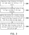
- FIG. 3 is a flowchart illustrating an inkjet coloring method of a 3-D printing apparatus according to an embodiment of the disclosure.
- the method of the present embodiment is applicable to the 3-D printing apparatus 100 illustrated in FIG. 2 , and detailed steps of the inkjet coloring method of the present embodiment will be described in detail below with reference to each element in the 3-D printing apparatus 100 .
- step S 301 the controller 130 obtains a layer thickness of at least one layer object 80 a or 80 c used for forming a 3-D object 80 .
- step S 302 the controller 130 adjusts an ink discharge volume of an ink layer according to the layer thickness, where the ink discharge volume is in positive correlation with the layer thickness.
- the controller 130 may adjust the ink discharge volume of each color ink in the ink layer according to the layer thickness. For instance, the controller 130 may determine the ink discharge volumes corresponding to four types of ink in four colors, i.e., cyan, magenta, yellow and black, according to the layer thickness.
- the layer thickness of each layer object for forming the 3-D object may be the same or different.
- the controller 130 may determine the ink discharge volume of each layer object according to one layer thickness. If the layer thicknesses of all the layer objects are different, the controller 130 may determine the ink discharge volume of each layer object according to one or more layer thicknesses.
- FIG. 4A and FIG. 4B are schematic diagrams illustrating the layer objects and the ink layers according to an embodiment of the disclosure. Referring to FIG.
- the controller 130 may control the inkjet head 140 to spray the ink 400 a according to an ink discharge volume determined based on the thickness h 1 , so as to form ink layers 40 b and 40 d .
- the controller 130 may control the inkjet head 140 to spray the ink 400 a according to an ink discharge volume determined based on the thickness h 1 , so as to form ink layers 40 b and 40 d .
- the controller 130 may control the inkjet head 140 to spray the ink 400 a according to the ink discharge volume determined based on the thickness h 1 , so as to form the ink layer 40 b , and control the inkjet head 140 to spray the ink 400 a according to an ink discharge volume determined based on the thickness h 2 , so as to form an ink layer 40 f . If the thickness h 2 is greater than the thickness h 1 , the ink discharge volume per unit area used to form the ink layer 40 f is greater than the ink discharge volume per unit area used to form the ink layer 40 d.
- step S 303 the controller 130 controls the 3-D printing head 120 to melt and print out the building material 20 a on the platform 110 according to the layer thickness, so as to form the layer objects 80 a and 80 c .
- step S 304 the controller 130 controls the inkjet head 140 to apply the at least one ink 400 a on the layer objects 80 a and 80 c according to the adjusted ink discharge volume, so as to form the ink layers 80 b and 80 d .
- the building material 20 a is, for example, a transparent or white material.
- the controller 130 may control an extrusion amount of the building material per unit time for the 3-D printing head 120 according to the layer thickness and control a moving path of the 3-D printing head 120 on the X-Y plane according to sectional contours of the layer objects 80 a and 80 c .
- the layer objects 80 a and 80 c which are presented in the transparent or white color and have the layer thicknesses are cured and formed on the platform 110 .
- the controller 130 may control the inkjet head 140 to apply the ink 400 a on the layer objects 80 a and 80 c according to the adjusted ink discharge volume, such that the layer objects 80 a and 80 c presented in the transparent or white color are dyed using the color of the ink 400 a to form the ink layers 80 b and 80 d .
- the ink discharge volume of the inkjet head 140 may be adjusted by changing a voltage applied to an electronic element of the inkjet nozzle 141 .
- the controller 130 may adjust the voltage applied to the electronic element of the inkjet nozzle 141 according to the layer thickness, so as to adjust the ink discharge volume by adjusting a droplet size of the ink ejected from the inkjet nozzle 141 .
- controller 130 may employ the layer thickness as a decision factor by using a lookup table or according to a specific equation, so as to determine the ink discharge volume.
- the reference thickness or a predetermined reference value corresponding to the reference thickness (which is a predetermined ink discharge volume) may be previously determined, such that the controller 130 may determine an ideal ink discharge volume of the layer thickness according to the predetermined reference value and a relationship between the layer thickness and the reference thickness. For example, when a difference between the layer thickness and the reference thickness is greater than a first threshold, the predetermined reference value may be adjusted by being added or subtracted by an adjustment gap to obtain the adjusted ink discharge volume. When the difference between the layer thickness and the reference thickness is greater than a second threshold which is greater than the first threshold, the predetermined reference value may be adjusted by being added or subtracted by the doubled adjustment gap to obtain the adjusted ink discharge volume.
- the controller may first obtain a relation polynomial, substitute the layer thickness into the relation polynomial, and adjust the ink discharge volume from the predetermined reference value corresponding to the reference thickness to an ideal value.
- FIG. 5A is a schematic diagram illustrating an example of determining the ink discharge volume according to a relation polynomial according to an embodiment of the disclosure.
- the relation polynomial used for determining the ink discharge volume may be a quadratic polynomial, as illustrated in formula (1).
- C′ a ⁇ h 2 +bh+c, a> 0, h> 0 (1)
- C′ represents an ideal value of the ink discharge volume
- c represents a constant and is greater than
- h represents the layer thickness and is greater than
- a and b represent adjustment coefficients.
- the adjustment coefficients a and b and the constant c may be generated through a test and an experiment taken place in advance.
- a designer may obtain a plurality of testing layer thicknesses and their respectively corresponding optimal ink discharge volumes through tests and approximate a curve equation according to the test data, so as to finally obtain the adjustment coefficients a and b and the constant c.
- a corresponding relationship 51 illustrated in FIG. 5A may be obtained.
- the controller 130 may substitute the thickness H 1 into formula (1) and accordingly determine that the ideal value of the ink discharge volume is R 2 .
- the layer thickness is in positive correlation with the ink discharge volume.
- the ink discharge volumes of the color ink in different colors may be determined according to formula (1) and the corresponding relationship 51 illustrated in FIG. 5A .
- FIG. 5B is a schematic diagram illustrating an example of determining the ink discharge volume according to a relation polynomial according to an embodiment of the disclosure.
- a reference thickness is H 2 , but the disclosure is not limited thereto.
- a relation polynomial used for determining the ink discharge volume may be a quadratic polynomial, as illustrated in formula (2).
- C ′ a ⁇ ( h - hp ) 2 + b ⁇ ( h - hp ) + c , ⁇ ⁇ if ⁇ ⁇ h ⁇ hp , then ⁇ ⁇ a > 0 if ⁇ ⁇ h ⁇ ⁇ p > h > 0 , then ⁇ ⁇ a ⁇ 0 ( 2 )
- C′ represents an ideal value of the ink discharge volume
- c represents a predetermined reference of the ink discharge volume of a reference thickness
- h represents a layer thickness and is greater than
- hp represents the reference thickness
- a and b represent adjustment coefficients.
- the predetermined reference value of the ink discharge volume is used as a based value employed for adjusting the ink discharge volume
- the predetermined reference value of the ink discharge volume is R 3 (i.e., the constant term c of formula (2) is R 3 ) corresponding to the reference thickness which is predetermined as a thickness H 2 (i.e., hp in formula (2) is H 2 ).
- the controller 130 may substitute the thickness H 2 into formula (2) and accordingly determine that the ideal value of the ink discharge volume is R 3 .
- the controller 130 may substitute the thickness H 3 into formula (2) and accordingly determine that the ideal value of the ink discharge volume is R 4 which is greater than the predetermined reference value. If it is assumed that the layer thickness of the layer object is a thickness H 4 which is less than the reference thickness, the controller 130 may substitute the thickness H 4 into formula (2) and accordingly determine that the ideal value of the ink discharge volume is R 5 which is less than the predetermined reference value.
- the layer thickness is in positive correlation with the ink discharge volume.
- the ink discharge volumes of the color ink in different colors may be determined according to formula (2) and the corresponding relationship 52 illustrated in FIG. 5B .
- the examples in FIG. 5A and FIG. 5B are only exemplarily illustrated and construe no limitations to the disclosure.
- the controller may further select a corresponding relation polynomial from a plurality of preset polynomials according to the material type of the building material 20 a , so as to determine the optimal ink discharge volume according to both the material type of the building material and the layer thickness.
- the preset polynomials described above are previously recorded in a recording medium, for example, and thus, when obtaining the material type of the building material 20 a , the 3-D printing apparatus 100 may select a relation polynomial corresponding to the currently used material type from the preset polynomials.
- the controller 130 may correspondingly select a relation polynomial corresponding to the PLA.
- the controller 130 may correspondingly select a relation polynomial corresponding to the ABS resin.
- the ink layer is directly formed on and directly dyes the layer object by the inkjet head and so repeated for several times, the layer objects and the ink layers are alternatively stacked in sequence, so as to form the color 3-D object.
- the structure of each layer of the 3-D object has a colored appearance that the overall color properties are enhanced, and different parts of each color-ink layer may have different colors to improve the color variability.
- the ink discharge volume of the inkjet head can be determined according to the layer thickness of the layer object, such that the phenomenon that the ink is incapable of completely applying to the bottom of the layer object can be avoided.
- the ink discharge volume can also be adjusted according to both the type of the building material and the layer thickness. In this way, each layer object can be ideally dyed, such that the color 3-D object composed of the layer objects can be provided with uniform color rendering effect.
Landscapes
- Engineering & Computer Science (AREA)
- Chemical & Material Sciences (AREA)
- Materials Engineering (AREA)
- Manufacturing & Machinery (AREA)
- Mechanical Engineering (AREA)
- Physics & Mathematics (AREA)
- Optics & Photonics (AREA)
- Human Computer Interaction (AREA)
- General Physics & Mathematics (AREA)
- Automation & Control Theory (AREA)
- Coating Apparatus (AREA)
- Ink Jet (AREA)
- Application Of Or Painting With Fluid Materials (AREA)
Applications Claiming Priority (3)
| Application Number | Priority Date | Filing Date | Title |
|---|---|---|---|
| TW106100261 | 2017-01-05 | ||
| TW106100261A TWI711531B (zh) | 2017-01-05 | 2017-01-05 | 立體列印裝置與其噴墨著色方法 |
| TW106100261A | 2017-01-05 |
Publications (2)
| Publication Number | Publication Date |
|---|---|
| US20180186089A1 US20180186089A1 (en) | 2018-07-05 |
| US10596801B2 true US10596801B2 (en) | 2020-03-24 |
Family
ID=58579082
Family Applications (1)
| Application Number | Title | Priority Date | Filing Date |
|---|---|---|---|
| US15/458,980 Expired - Fee Related US10596801B2 (en) | 2017-01-05 | 2017-03-15 | Three-dimensional printing apparatus and inkjet coloring method thereof |
Country Status (7)
| Country | Link |
|---|---|
| US (1) | US10596801B2 (zh) |
| EP (1) | EP3345741B1 (zh) |
| JP (1) | JP6604995B2 (zh) |
| KR (1) | KR102046156B1 (zh) |
| CN (1) | CN108274737B (zh) |
| ES (1) | ES2741835T3 (zh) |
| TW (1) | TWI711531B (zh) |
Families Citing this family (6)
| Publication number | Priority date | Publication date | Assignee | Title |
|---|---|---|---|---|
| EP3584087B1 (en) * | 2015-05-27 | 2021-09-08 | NIKE Innovate C.V. | Color density based thickness compensation printing |
| TWI668124B (zh) * | 2017-01-06 | 2019-08-11 | 三緯國際立體列印科技股份有限公司 | 立體列印上色方法與立體列印系統 |
| CN110126274A (zh) * | 2019-05-29 | 2019-08-16 | 吴振行 | 一种多彩喷墨3d打印方法 |
| US11718040B2 (en) | 2020-02-18 | 2023-08-08 | Drew Alexander Williams | 3D printed sculptures and process |
| CN112873846B (zh) * | 2020-12-22 | 2022-12-09 | 浙江理工大学 | 一种3d打印机及其挤丝装置 |
| CN113183470B (zh) * | 2021-05-12 | 2022-07-15 | 电子科技大学 | 一种保留模型非常规特征的3d打印自适应分层方法 |
Citations (8)
| Publication number | Priority date | Publication date | Assignee | Title |
|---|---|---|---|---|
| US20070146734A1 (en) | 2005-12-28 | 2007-06-28 | Canon Kabushiki Kaisha | Method for manufacturing three-dimensional object, three-dimensional object, and print medium |
| US20140291886A1 (en) * | 2013-03-22 | 2014-10-02 | Gregory Thomas Mark | Three dimensional printing |
| WO2015163776A1 (en) | 2014-04-24 | 2015-10-29 | Pluciennik Tomasz | A method for additive manufacturing of a spatial 3d object and a device for additive manufacturing of a spatial 3d object |
| JP2015221568A (ja) | 2010-10-27 | 2015-12-10 | ファイル2パート インコーポレイテッド | 三次元物体の造形プロセスおよび造形装置 |
| WO2015199019A1 (ja) | 2014-06-24 | 2015-12-30 | 株式会社ミマキエンジニアリング | 三次元印刷装置および三次元印刷方法 |
| JP2016097632A (ja) | 2014-11-25 | 2016-05-30 | セイコーエプソン株式会社 | 三次元造形物の製造方法、三次元造形物製造装置および三次元造形物 |
| WO2016142930A1 (en) | 2015-03-12 | 2016-09-15 | Massivit 3D Printing Technologies Ltd. | A machine for 3d objects manufacture |
| JP2016185625A (ja) | 2015-03-27 | 2016-10-27 | 日本電信電話株式会社 | 三次元造形装置及び三次元造形方法 |
-
2017
- 2017-01-05 TW TW106100261A patent/TWI711531B/zh active
- 2017-02-22 CN CN201710095667.8A patent/CN108274737B/zh not_active Expired - Fee Related
- 2017-03-15 US US15/458,980 patent/US10596801B2/en not_active Expired - Fee Related
- 2017-04-12 KR KR1020170047583A patent/KR102046156B1/ko active IP Right Grant
- 2017-04-20 ES ES17167321T patent/ES2741835T3/es active Active
- 2017-04-20 EP EP17167321.3A patent/EP3345741B1/en active Active
- 2017-06-05 JP JP2017110543A patent/JP6604995B2/ja not_active Expired - Fee Related
Patent Citations (9)
| Publication number | Priority date | Publication date | Assignee | Title |
|---|---|---|---|---|
| US20070146734A1 (en) | 2005-12-28 | 2007-06-28 | Canon Kabushiki Kaisha | Method for manufacturing three-dimensional object, three-dimensional object, and print medium |
| JP2007196668A (ja) | 2005-12-28 | 2007-08-09 | Canon Inc | 立体物の製造方法、立体物、立体物製造用記録媒体、及び立体物の製造装置 |
| JP2015221568A (ja) | 2010-10-27 | 2015-12-10 | ファイル2パート インコーポレイテッド | 三次元物体の造形プロセスおよび造形装置 |
| US20140291886A1 (en) * | 2013-03-22 | 2014-10-02 | Gregory Thomas Mark | Three dimensional printing |
| WO2015163776A1 (en) | 2014-04-24 | 2015-10-29 | Pluciennik Tomasz | A method for additive manufacturing of a spatial 3d object and a device for additive manufacturing of a spatial 3d object |
| WO2015199019A1 (ja) | 2014-06-24 | 2015-12-30 | 株式会社ミマキエンジニアリング | 三次元印刷装置および三次元印刷方法 |
| JP2016097632A (ja) | 2014-11-25 | 2016-05-30 | セイコーエプソン株式会社 | 三次元造形物の製造方法、三次元造形物製造装置および三次元造形物 |
| WO2016142930A1 (en) | 2015-03-12 | 2016-09-15 | Massivit 3D Printing Technologies Ltd. | A machine for 3d objects manufacture |
| JP2016185625A (ja) | 2015-03-27 | 2016-10-27 | 日本電信電話株式会社 | 三次元造形装置及び三次元造形方法 |
Non-Patent Citations (2)
| Title |
|---|
| "Office Action of Japan Counterpart Application," dated Mar. 5, 2019, p. 1-3. |
| Office Action of Taiwan Counterpart Application, dated Dec. 3, 2018, pp. 1-7. |
Also Published As
| Publication number | Publication date |
|---|---|
| TW201825263A (zh) | 2018-07-16 |
| JP6604995B2 (ja) | 2019-11-13 |
| ES2741835T3 (es) | 2020-02-12 |
| US20180186089A1 (en) | 2018-07-05 |
| EP3345741A1 (en) | 2018-07-11 |
| KR102046156B1 (ko) | 2019-11-18 |
| CN108274737B (zh) | 2020-05-19 |
| EP3345741B1 (en) | 2019-05-22 |
| KR20180080954A (ko) | 2018-07-13 |
| JP2018108725A (ja) | 2018-07-12 |
| TWI711531B (zh) | 2020-12-01 |
| CN108274737A (zh) | 2018-07-13 |
Similar Documents
| Publication | Publication Date | Title |
|---|---|---|
| US10596801B2 (en) | Three-dimensional printing apparatus and inkjet coloring method thereof | |
| CN104085107B (zh) | 三维打印机、三维打印机的打印方法及其打印装置 | |
| TWI674978B (zh) | 彩色立體列印方法與立體列印設備 | |
| US20180071988A1 (en) | Three-dimensional printing systems | |
| US10710376B2 (en) | Inkjet position adjustment method and three-dimensional printing equipment | |
| JP6902365B2 (ja) | 立体物造形方法及び3次元プリンタ | |
| JP2006515813A (ja) | 固体自由形状製造により物体を作成する方法およびシステム | |
| KR102182703B1 (ko) | 인쇄 헤드 모듈 | |
| US10105901B2 (en) | Rapid prototyping apparatus with page-width array printing module | |
| CN108602278A (zh) | 熔合灯校准 | |
| TW201900389A (zh) | 立體列印方法 | |
| KR102187223B1 (ko) | 잉크젯 폭 조절 방법 및 3차원 출력 장비 | |
| CN112789158B (zh) | 用于选择物体的方位和/或位置的方法、装置和介质 | |
| CN112166025B (zh) | 三维物体生产 | |
| TWI716704B (zh) | 噴墨寬度調整方法以及立體列印設備 | |
| TWI716703B (zh) | 噴墨位置調整方法以及立體列印設備 |
Legal Events
| Date | Code | Title | Description |
|---|---|---|---|
| AS | Assignment |
Owner name: XYZPRINTING, INC., TAIWAN Free format text: ASSIGNMENT OF ASSIGNORS INTEREST;ASSIGNORS:CHANG, YU-CHUAN;HSIEH, HSIN-TA;REEL/FRAME:041602/0669 Effective date: 20170314 Owner name: KINPO ELECTRONICS, INC., TAIWAN Free format text: ASSIGNMENT OF ASSIGNORS INTEREST;ASSIGNORS:CHANG, YU-CHUAN;HSIEH, HSIN-TA;REEL/FRAME:041602/0669 Effective date: 20170314 |
|
| STPP | Information on status: patent application and granting procedure in general |
Free format text: NON FINAL ACTION MAILED |
|
| STPP | Information on status: patent application and granting procedure in general |
Free format text: RESPONSE TO NON-FINAL OFFICE ACTION ENTERED AND FORWARDED TO EXAMINER |
|
| STPP | Information on status: patent application and granting procedure in general |
Free format text: EX PARTE QUAYLE ACTION MAILED |
|
| STPP | Information on status: patent application and granting procedure in general |
Free format text: NOTICE OF ALLOWANCE MAILED -- APPLICATION RECEIVED IN OFFICE OF PUBLICATIONS |
|
| STPP | Information on status: patent application and granting procedure in general |
Free format text: PUBLICATIONS -- ISSUE FEE PAYMENT VERIFIED |
|
| STCF | Information on status: patent grant |
Free format text: PATENTED CASE |
|
| FEPP | Fee payment procedure |
Free format text: MAINTENANCE FEE REMINDER MAILED (ORIGINAL EVENT CODE: REM.); ENTITY STATUS OF PATENT OWNER: LARGE ENTITY |
|
| LAPS | Lapse for failure to pay maintenance fees |
Free format text: PATENT EXPIRED FOR FAILURE TO PAY MAINTENANCE FEES (ORIGINAL EVENT CODE: EXP.); ENTITY STATUS OF PATENT OWNER: LARGE ENTITY |
|
| STCH | Information on status: patent discontinuation |
Free format text: PATENT EXPIRED DUE TO NONPAYMENT OF MAINTENANCE FEES UNDER 37 CFR 1.362 |
|
| FP | Lapsed due to failure to pay maintenance fee |
Effective date: 20240324 |