US10580447B2 - Magnetic recording medium with controlled surface characteristics - Google Patents
Magnetic recording medium with controlled surface characteristics Download PDFInfo
- Publication number
- US10580447B2 US10580447B2 US15/573,374 US201615573374A US10580447B2 US 10580447 B2 US10580447 B2 US 10580447B2 US 201615573374 A US201615573374 A US 201615573374A US 10580447 B2 US10580447 B2 US 10580447B2
- Authority
- US
- United States
- Prior art keywords
- layer
- recording medium
- magnetic
- magnetic recording
- medium according
- Prior art date
- Legal status (The legal status is an assumption and is not a legal conclusion. Google has not performed a legal analysis and makes no representation as to the accuracy of the status listed.)
- Active, expires
Links
Images


Classifications
-
- G—PHYSICS
- G11—INFORMATION STORAGE
- G11B—INFORMATION STORAGE BASED ON RELATIVE MOVEMENT BETWEEN RECORD CARRIER AND TRANSDUCER
- G11B5/00—Recording by magnetisation or demagnetisation of a record carrier; Reproducing by magnetic means; Record carriers therefor
- G11B5/62—Record carriers characterised by the selection of the material
- G11B5/73—Base layers, i.e. all non-magnetic layers lying under a lowermost magnetic recording layer, e.g. including any non-magnetic layer in between a first magnetic recording layer and either an underlying substrate or a soft magnetic underlayer
- G11B5/7368—Non-polymeric layer under the lowermost magnetic recording layer
-
- G—PHYSICS
- G11—INFORMATION STORAGE
- G11B—INFORMATION STORAGE BASED ON RELATIVE MOVEMENT BETWEEN RECORD CARRIER AND TRANSDUCER
- G11B5/00—Recording by magnetisation or demagnetisation of a record carrier; Reproducing by magnetic means; Record carriers therefor
- G11B5/62—Record carriers characterised by the selection of the material
- G11B5/64—Record carriers characterised by the selection of the material comprising only the magnetic material without bonding agent
- G11B5/66—Record carriers characterised by the selection of the material comprising only the magnetic material without bonding agent the record carriers consisting of several layers
- G11B5/667—Record carriers characterised by the selection of the material comprising only the magnetic material without bonding agent the record carriers consisting of several layers including a soft magnetic layer
-
- G—PHYSICS
- G11—INFORMATION STORAGE
- G11B—INFORMATION STORAGE BASED ON RELATIVE MOVEMENT BETWEEN RECORD CARRIER AND TRANSDUCER
- G11B5/00—Recording by magnetisation or demagnetisation of a record carrier; Reproducing by magnetic means; Record carriers therefor
- G11B5/62—Record carriers characterised by the selection of the material
- G11B5/64—Record carriers characterised by the selection of the material comprising only the magnetic material without bonding agent
- G11B5/65—Record carriers characterised by the selection of the material comprising only the magnetic material without bonding agent characterised by its composition
- G11B5/653—Record carriers characterised by the selection of the material comprising only the magnetic material without bonding agent characterised by its composition containing Fe or Ni
-
- G—PHYSICS
- G11—INFORMATION STORAGE
- G11B—INFORMATION STORAGE BASED ON RELATIVE MOVEMENT BETWEEN RECORD CARRIER AND TRANSDUCER
- G11B5/00—Recording by magnetisation or demagnetisation of a record carrier; Reproducing by magnetic means; Record carriers therefor
- G11B5/62—Record carriers characterised by the selection of the material
- G11B5/64—Record carriers characterised by the selection of the material comprising only the magnetic material without bonding agent
- G11B5/65—Record carriers characterised by the selection of the material comprising only the magnetic material without bonding agent characterised by its composition
- G11B5/656—Record carriers characterised by the selection of the material comprising only the magnetic material without bonding agent characterised by its composition containing Co
-
- G—PHYSICS
- G11—INFORMATION STORAGE
- G11B—INFORMATION STORAGE BASED ON RELATIVE MOVEMENT BETWEEN RECORD CARRIER AND TRANSDUCER
- G11B5/00—Recording by magnetisation or demagnetisation of a record carrier; Reproducing by magnetic means; Record carriers therefor
- G11B5/62—Record carriers characterised by the selection of the material
- G11B5/64—Record carriers characterised by the selection of the material comprising only the magnetic material without bonding agent
- G11B5/65—Record carriers characterised by the selection of the material comprising only the magnetic material without bonding agent characterised by its composition
- G11B5/658—Record carriers characterised by the selection of the material comprising only the magnetic material without bonding agent characterised by its composition containing oxygen, e.g. molecular oxygen or magnetic oxide
-
- G—PHYSICS
- G11—INFORMATION STORAGE
- G11B—INFORMATION STORAGE BASED ON RELATIVE MOVEMENT BETWEEN RECORD CARRIER AND TRANSDUCER
- G11B5/00—Recording by magnetisation or demagnetisation of a record carrier; Reproducing by magnetic means; Record carriers therefor
- G11B5/62—Record carriers characterised by the selection of the material
- G11B5/64—Record carriers characterised by the selection of the material comprising only the magnetic material without bonding agent
- G11B5/66—Record carriers characterised by the selection of the material comprising only the magnetic material without bonding agent the record carriers consisting of several layers
- G11B5/674—Record carriers characterised by the selection of the material comprising only the magnetic material without bonding agent the record carriers consisting of several layers having differing macroscopic or microscopic structures, e.g. differing crystalline lattices, varying atomic structures or differing roughnesses
-
- G—PHYSICS
- G11—INFORMATION STORAGE
- G11B—INFORMATION STORAGE BASED ON RELATIVE MOVEMENT BETWEEN RECORD CARRIER AND TRANSDUCER
- G11B5/00—Recording by magnetisation or demagnetisation of a record carrier; Reproducing by magnetic means; Record carriers therefor
- G11B5/62—Record carriers characterised by the selection of the material
- G11B5/68—Record carriers characterised by the selection of the material comprising one or more layers of magnetisable material homogeneously mixed with a bonding agent
- G11B5/70—Record carriers characterised by the selection of the material comprising one or more layers of magnetisable material homogeneously mixed with a bonding agent on a base layer
-
- G—PHYSICS
- G11—INFORMATION STORAGE
- G11B—INFORMATION STORAGE BASED ON RELATIVE MOVEMENT BETWEEN RECORD CARRIER AND TRANSDUCER
- G11B5/00—Recording by magnetisation or demagnetisation of a record carrier; Reproducing by magnetic means; Record carriers therefor
- G11B5/62—Record carriers characterised by the selection of the material
- G11B5/73—Base layers, i.e. all non-magnetic layers lying under a lowermost magnetic recording layer, e.g. including any non-magnetic layer in between a first magnetic recording layer and either an underlying substrate or a soft magnetic underlayer
- G11B5/733—Base layers, i.e. all non-magnetic layers lying under a lowermost magnetic recording layer, e.g. including any non-magnetic layer in between a first magnetic recording layer and either an underlying substrate or a soft magnetic underlayer characterised by the addition of non-magnetic particles
-
- G—PHYSICS
- G11—INFORMATION STORAGE
- G11B—INFORMATION STORAGE BASED ON RELATIVE MOVEMENT BETWEEN RECORD CARRIER AND TRANSDUCER
- G11B5/00—Recording by magnetisation or demagnetisation of a record carrier; Reproducing by magnetic means; Record carriers therefor
- G11B5/62—Record carriers characterised by the selection of the material
- G11B5/73—Base layers, i.e. all non-magnetic layers lying under a lowermost magnetic recording layer, e.g. including any non-magnetic layer in between a first magnetic recording layer and either an underlying substrate or a soft magnetic underlayer
- G11B5/736—Non-magnetic layer under a soft magnetic layer, e.g. between a substrate and a soft magnetic underlayer [SUL] or a keeper layer
-
- G—PHYSICS
- G11—INFORMATION STORAGE
- G11B—INFORMATION STORAGE BASED ON RELATIVE MOVEMENT BETWEEN RECORD CARRIER AND TRANSDUCER
- G11B5/00—Recording by magnetisation or demagnetisation of a record carrier; Reproducing by magnetic means; Record carriers therefor
- G11B5/62—Record carriers characterised by the selection of the material
- G11B5/73—Base layers, i.e. all non-magnetic layers lying under a lowermost magnetic recording layer, e.g. including any non-magnetic layer in between a first magnetic recording layer and either an underlying substrate or a soft magnetic underlayer
- G11B5/7368—Non-polymeric layer under the lowermost magnetic recording layer
- G11B5/7369—Two or more non-magnetic underlayers, e.g. seed layers or barrier layers
-
- G—PHYSICS
- G11—INFORMATION STORAGE
- G11B—INFORMATION STORAGE BASED ON RELATIVE MOVEMENT BETWEEN RECORD CARRIER AND TRANSDUCER
- G11B5/00—Recording by magnetisation or demagnetisation of a record carrier; Reproducing by magnetic means; Record carriers therefor
- G11B5/62—Record carriers characterised by the selection of the material
- G11B5/73—Base layers, i.e. all non-magnetic layers lying under a lowermost magnetic recording layer, e.g. including any non-magnetic layer in between a first magnetic recording layer and either an underlying substrate or a soft magnetic underlayer
- G11B5/739—Magnetic recording media substrates
- G11B5/73923—Organic polymer substrates
- G11B5/73925—Composite or coated non-esterified substrates
-
- G—PHYSICS
- G11—INFORMATION STORAGE
- G11B—INFORMATION STORAGE BASED ON RELATIVE MOVEMENT BETWEEN RECORD CARRIER AND TRANSDUCER
- G11B5/00—Recording by magnetisation or demagnetisation of a record carrier; Reproducing by magnetic means; Record carriers therefor
- G11B5/62—Record carriers characterised by the selection of the material
- G11B5/73—Base layers, i.e. all non-magnetic layers lying under a lowermost magnetic recording layer, e.g. including any non-magnetic layer in between a first magnetic recording layer and either an underlying substrate or a soft magnetic underlayer
- G11B5/739—Magnetic recording media substrates
- G11B5/73923—Organic polymer substrates
- G11B5/73927—Polyester substrates, e.g. polyethylene terephthalate
- G11B5/73935—Polyester substrates, e.g. polyethylene terephthalate characterised by roughness or surface features, e.g. by added particles
Definitions
- the present technique relates to a magnetic recording medium, and more particularly relates to a magnetic recording medium for use in recording data or the like.
- Patent Literature 1 discloses a magnetic recording medium in which at least an amorphous layer, a seed layer, a foundation layer, a magnetic layer, and a protective layer are successively formed on a nonmagnetic base material.
- the present technique has an object to provide a magnetic recording medium that can achieve both good recording and reproducing properties and low high-speed friction.
- the present technique is a magnetic recording medium including: a base substance having flexibility; a crystal control layer provided on the base substance; and a magnetic layer provided on the crystal control layer.
- the magnetic recording medium has a recording surface having an average surface roughness SRa of 3.0 nm or less, the number of projections having a height of 7.5 nm or more included in a unit region (where the unit region is a square region with each side having a length of 30 ⁇ m) of the recording surface is 256 or more, and the number of projections having a height of 15 nm or more included in the unit region of the recording surface is 0 or more and 104 or less.
- FIG. 1 is a cross sectional view schematically illustrating an example of the configuration of a magnetic recording medium according to a first embodiment of the present technique.
- FIG. 2 is a schematic view schematically illustrating an example of the configuration of a sputtering device for use in manufacturing of the magnetic recording medium according to the first embodiment of the present technique.
- FIG. 3 is a cross sectional view schematically illustrating an example of the configuration of a magnetic recording medium according to a second embodiment of the present technique.
- FIG. 4 is a cross sectional view schematically illustrating an example of the configuration of a magnetic recording medium according to a third embodiment of the present technique.
- FIG. 5 is a cross sectional view schematically illustrating an example of the configuration of a magnetic recording medium according to a fourth embodiment of the present technique.
- FIG. 6 is a cross sectional view schematically illustrating an example of the configuration of a magnetic recording medium according to a fifth embodiment of the present technique.
- FIG. 7 is a cross sectional view schematically illustrating an example of the configuration of a magnetic recording medium according to a sixth embodiment of the present technique.
- FIG. 8 is a graph illustrating a relation between the number of projections having a height of 7.5 nm or more included in a unit region and recording and reproducing properties.
- FIG. 9 is a graph illustrating a relation between the number of projections having a height of 15 nm or more included in a unit region and recording and reproducing properties.
- FIG. 10 is a graph illustrating a relation between the number of projections having a height of 7.5 nm or more included in the unit region and a high-speed frictional force.
- FIG. 11 is a graph illustrating a relation between the number of projections having a height of 15 nm or more included in the unit region and a high-speed frictional force.
- FIG. 12 is a graph illustrating a relation between the number of projections having a height of 7.5 nm or more and the number of projections having a height of 15 nm or more included in the unit region and evaluation results of recording and reproducing properties and a high-speed frictional force.
- FIG. 13 is a cross sectional view schematically illustrating an example of the configuration of a magnetic recording medium according to a seventh embodiment of the present technique.
- FIG. 14 is a cross sectional view schematically illustrating an example of the configuration of a magnetic recording medium according to a modification of the seventh embodiment of the present technique.
- Embodiments of the present technique are described in the following order.
- (A) There is a correlation between the number of projections having a height of 7.5 nm or more included in a unit region (where the unit region is a square region with each side having a length of 30 ⁇ m) of a recording surface and high-speed friction, and if the number of projections having a height of 7.5 nm or more included in the unit region is 256 or more, low high-speed friction is obtained.
- (B) There is a correlation between the number of projections having a height of 15 nm or more included in the unit region of the recording surface and recording and reproducing properties, and if the number of projections having a height of 15 nm or more included in the unit region is 0 or more and 104 or less, good recording and reproducing properties are obtained.
- the inventors of the present application have found out the following. That is, when the number of projections having a height of 7.5 nm or more included in the unit region of the recording surface is 256 or more and the number of projections having a height of 15 nm or more included in the unit region of the recording surface is 0 or more and 104 or less under the condition that the average surface roughness SRa satisfies the relation SRa ⁇ 3.0 nm, it is possible to achieve both good recording and reproducing properties and low high-speed friction.
- a magnetic recording medium according to a first embodiment of the present technique is a single layer vertical magnetic recording medium having a so-called long shape, and as illustrated in FIG. 1 , includes a base substance 11 , a crystal control layer 12 provided on one major surface (hereinafter referred to as a “surface”) of the base substance 11 , a magnetic layer 13 provided on the crystal control layer 12 , a protective layer 14 provided on the magnetic layer 13 , and a lubricant layer 15 provided on the protective layer 14 .
- the magnetic recording medium according to the first embodiment further includes a backcoat layer 16 provided on the other major surface (hereinafter referred to as a “rear surface”) of the base substance 11 .
- the crystal control layer 12 includes a seed layer 21 provided on the surface of the base substance 11 , and a foundation layer 22 provided on the seed layer 21 . It is preferable that a laminated film composed of the crystal control layer 12 , the magnetic layer 13 , and the protective layer 14 is a sputtering film formed by a sputtering method.
- a recording medium not having a soft magnetic underlayer is referred to as a “single layer vertical magnetic recording medium”, and a recording medium having a soft magnetic underlayer as a “two-layer vertical magnetic recording medium” in the present specification.
- a major surface on the side with which a recording head or recording and reproducing head makes contact when recording an information signal is referred to as a recording surface.
- the magnetic recording medium according to the first embodiment is suitably used as storage media for data archives for which a demand is expected to further increase in the future.
- the magnetic recording medium can realize a surface recording density of 10 times or more that of a current coating type magnetic tape for storage, i.e., surface recording density of 50 Gb/in 2 , for example.
- surface recording density of 50 Gb/in 2
- mass recording of 50 TB or more per data cartridge can be achieved.
- the magnetic recording medium is suitably used for a recording and reproducing device employing a ring type recording head and a giant magnetoresistive (GMR) type reproducing head.
- GMR giant magnetoresistive
- the magnetic recording medium according to the first embodiment has a recording surface having a long shape.
- the recording surface has microscopic unevenness.
- the average surface roughness SRa of the recording surface is 3.0 nm or less. If the average surface roughness SRa exceeds 3.0 nm, there is a tendency that good recording and reproducing properties cannot be obtained.
- the number of projections having a height of 7.5 nm or more included in the unit region of the recording surface is 256 or more, preferably 256 or more and 3000 or less. If the number of projections having a height of 7.5 nm or more is less than 256, high-speed friction of the recording surface tends to increase. From the viewpoint of reducing high-speed friction of the recording surface, the number of projections having a height of 7.5 nm or more included in the unit region of the recording surface is preferably 500 or more and 3000 or less, more preferably 1000 or more and 3000 or less, still more preferably 2000 or more and 3000 or less, and most preferably 2500 or more and 3000 or less.
- the unit region refers to a square measurement region with each side having a length of 30 ⁇ m.
- the number of projections having a height of 15 nm or more included in the unit region of the recording surface is 0 or more and 104 or less. If the number of projections having a height of 15 nm or more exceeds 104, recording and reproducing properties tend to deteriorate. From the viewpoint of improving recording and reproducing properties, the number of projections having a height of 15 nm or more included in the unit region of the recording surface is preferably 0 or more and 75 or less, more preferably 0 or more and 50 or less, still more preferably 0 or more and 25 or less, and most preferably 0 or more and 10 or less.
- the base substance 11 to be a base material has a long shape.
- the base substance 11 has an uneven surface including microscopic unevenness on the recording surface side.
- the uneven surface of the base substance 11 has an uneven shape substantially similar to the unevenness of the recording surface.
- the average surface roughness SRa of the surface of the base substance 11 is 3.0 nm or less.
- the number of projections having a height of 7.5 nm or more included in the unit region of the surface of the base substance 11 is 256 or more and 3000 or less.
- the number of projections having a height of 15 nm or more included in the unit region of the surface of the base substance 11 is 0 or more and 104 or less.
- the recording surface can be an uneven surface that substantially conforms to the uneven surface of the base substance 11 to form the recording surface that satisfies the average surface roughness SRa and the number of projections described above by laminating the crystal control layer 12 , the magnetic layer 13 , and the protective layer 14 so as to conform to the uneven surface of the base substance 11 .
- the number of projections having a height of 7.5 nm or more included in the unit region of the uneven surface of the base substance 11 is preferably 500 or more and 3000 or less, more preferably 1000 or more and 3000 or less, still more preferably 2000 or more and 3000 or less, and most preferably 2500 or more and 3000 or less.
- the number of projections having a height of 15 nm or more included in the unit region of the uneven surface of the base substance 11 is preferably 0 or more and 75 or less, more preferably 0 or more and 50 or less, still more preferably 0 or more and 25 or less, and most preferably 0 or more and 10 or less.
- the base substance 11 is a nonmagnetic base substance having flexibility, specifically, a polymer film.
- a material of the nonmagnetic base substance a flexible polymer resin material for use in the nonmagnetic base substance of general magnetic recording media can be used, for example.
- Specific examples of such a polymer material include polyesters, polyolefins, cellulose derivatives, vinyl resin, polyimides, polyamides, polycarbonate, or the like.
- the seed layer 21 contains an alloy containing Ti and Cr and the alloy has an amorphous state. Specifically, it is preferable for the seed layer 21 to contain an alloy containing Ti and Cr and to have an amorphous state.
- the alloy may further contain O (oxygen).
- the oxygen is impurity oxygen contained in a small proportion in the seed layer 21 when forming the seed layer 21 by a film forming method, such as a sputtering method, for example.
- the “seed layer” does not refer to an intermediate layer having a crystal structure similar to that of the foundation layer 22 and provided for crystal growth and refers to an intermediate layer which improves the vertical orientation properties of the foundation layer 22 due to the amorphous state of the seed layer 21 .
- the “alloy” means at least one of a solid solution containing Ti and Cr, an eutectic crystal, an intermetallic compound, and the like.
- the “amorphous state” means that halo is observed by an electron diffraction method and the crystal structure may not be specified.
- the seed layer 21 containing an alloy containing Ti and Cr and having an amorphous state has effects of suppressing the influence of O 2 gas and H 2 O adsorbing to the base substance 11 . Due to the effects, the vertical orientation properties of the foundation layer 22 are improved.
- the proportion of O (oxygen) based on the total amount of Ti, Cr, and O contained in the seed layer 21 is preferably 15 atomic % (at %) or less and more preferably 10 atomic % or less.
- the proportion of oxygen exceeds 15 atomic %, a TiO 2 crystal generates, which exerts an influence on the formation of the crystal nucleus of the foundation layer 22 to be formed on the surface of the seed layer 21 , so that the orientation properties of the foundation layer 22 greatly decrease.
- the proportion of Ti based on the total amount of Ti and Cr contained in the seed layer 21 is preferably in the range of 30 atomic % or more and 100 atomic % or less and more preferably in the range of 50 atomic % or more and 100 atomic % or less.
- the proportion of Ti is less than 30%, the (100) plane of the body-centered cubiclattice (bcc) structure of Cr is oriented, so that the orientation properties of the foundation layer 22 to be formed on the surface of the seed layer 21 decreases.
- the proportion of the elements above can be determined as follows. Etching by ion beams is performed from the side of the lubricant layer 15 of the magnetic recording medium, the outermost surface of the etched the seed layer 21 is subjected to an analysis by Auger electron spectroscopy, and then the average atomic number ratio based on the film thickness is defined as the proportion of the element. Specifically, the three elements of Ti, Cr, and O are analyzed, and then the element amount in terms of percentage ratio is identified.
- the alloy contained in the seed layer 21 may further contain elements other than Ti and Cr as additional elements.
- additional elements include one or more elements selected from the group consisting of Nb, Ni, Mo, Al, W, and the like, for example.
- the foundation layer 22 it is preferable for the foundation layer 22 to have the same crystal structure as that of the magnetic layer 13 .
- the magnetic layer 13 contains a Co alloy
- the foundation layer 22 contains a material having the same hexagonal close-packed (hcp) structure as that of the Co alloy and that the c-axis of the structure is vertically oriented (i.e., film thickness direction) to the film surface. This is because the orientation properties of the magnetic layer 13 can be improved and the grating constants of the foundation layer 22 and the magnetic layer 13 can be relatively favorably matched.
- the material having the hexagonal close-packed (hcp) structure materials containing Ru are preferably used and specifically a Ru simple substance or a Ru alloy is preferable. Examples of the Ru alloy include Ru alloy oxides, such as Ru—SiO 2 , Ru—TiO 2 , or Ru—ZrO 2 , for example.
- the magnetic layer 13 is preferably a granular magnetic layer containing a Co alloy from the viewpoint of improving recording density.
- This granular magnetic layer contains ferromagnetic crystal particles containing a Co alloy and a nonmagnetic grain boundary (nonmagnetic material) surrounding the ferromagnetic crystal particles. More specifically, the granular magnetic layer contains columns (columnar crystal) containing a Co alloy and a nonmagnetic grain boundary (for example, oxides, such as SiO 2 ) which surrounds the columns and which magnetically isolate each column.
- This structure can constitute the magnetic layer 13 having the structure in which each column is magnetically isolated.
- the Co alloy has the hexagonal close-packed (hcp) structure, in which the c-axis is vertically oriented (film thickness direction) to the film surface.
- hcp hexagonal close-packed
- a CoCrPt alloy at least containing Co, Cr, and Pt is preferably used.
- the CoCrPt alloy is not particularly limited and the CoCrPt alloy may further contain additional elements. Examples of the additional elements include one or more elements selected from the group consisting of Ni, Ta, and the like, for example.
- the nonmagnetic grain boundary surrounding the ferromagnetic crystal particles contains a nonmagnetic metal material.
- the metal includes semimetal.
- the nonmagnetic metal material at least one of a metal oxide and a metal nitride can be used, for example. From the viewpoint of more stably maintaining the granular structure, a metal oxide is preferably used.
- the metal oxide include a metal oxide containing at least one or more elements selected from the group consisting of Si, Cr, Co, Al, Ti, Ta, Zr, Ce, Y, Hf, and the like and a metal oxide containing at least a Si oxide (i.e., SiO 2 ) is preferable.
- the nonmagnetic grain boundary In order to more stably maintain the granular structure, it is preferable for the nonmagnetic grain boundary to contain a metal oxide among the metal nitrides and the metal oxides.
- the CoCrPt alloy contained in the ferromagnetic crystal particles and the Si oxide contained in the nonmagnetic grain boundary prefferably have the average composition shown in the following expression. This is because the influence of a demagnetizing field can be suppressed and also the saturation magnetization Ms capable of securing a sufficient reproduction output can be realized and a high SNR can be secured.
- (Co x Pt y Cr 100-x-y ) 100-z —(SiO 2 ) z (In the expression, x, y, and z are values in the range of 69 ⁇ X ⁇ 72, 12 ⁇ y ⁇ 16, and 9 ⁇ Z ⁇ 12, respectively.)
- the composition above can be determined as follows. Etching by ion beams is performed from the side of the lubricant layer 15 of the magnetic recording medium, the outermost surface of the etched magnetic layer 13 is subjected to an analysis by Auger electron spectroscopy, and then the average atomic number ratio based on the film thickness is defined as the proportion of the element. Specifically, the five elements of Co, Pt, Cr, Si, and O are analyzed, and then the element amount in terms of percentage ratio is identified.
- the magnetic recording medium according to this embodiment is a single layer magnetic recording medium which does not have an underlayer (soft magnetic underlayer) containing a soft magnetic material.
- an underlayer soft magnetic underlayer
- the demagnetizing field becomes larger in proportion to the saturation magnetization Ms of the magnetic layer 13 . Therefore, in order to suppress the demagnetizing field, it is preferable to reduce the saturation magnetization Ms. However, when the saturation magnetization Ms becomes small, the remaining magnetization Mr becomes small, so that a reproduction output decreases.
- the materials contained in the magnetic layer 13 are preferably selected from the viewpoint of achieving both the suppression of the influence of the demagnetizing field (i.e., reduction in the saturation magnetization Ms) and the remaining magnetization Mr capable of securing a sufficient reproduction output. In the average composition of the expression above, both these properties can be achieved and a high SNR can be secured.
- At least two adjacent layers among the seed layer 21 , the foundation layer 22 , and the magnetic layer 13 are continuously formed by a Roll to Roll method and it is more preferable that all the three layers are continuously formed by a Roll to Roll method. This is because the magnetic properties and the recording and reproducing properties can be further improved.
- the protective layer 14 contains a carbon material or a silica dioxide (SiO 2 ), for example, and preferably contains a carbon material from the viewpoint of the film strength of the protective layer 14 .
- the carbon material include graphite, diamond-like carbon (DLC), diamond, or the like, for example.
- the lubricant layer 15 contains a lubricant, for example.
- a lubricant for example.
- silicone lubricants, hydrocarbon lubricants, fluorinated hydrocarbon lubricants, or the like can be used, for example.
- the backcoat layer 16 contains a binder, inorganic particles, and a lubricant.
- the backcoat layer 16 may contain various additives, such as a curing agent and an antistatic agent, according to necessity.
- the sputtering device is a continuous take-up sputtering device for use in the film formation of the seed layer 21 , the foundation layer 22 , and the magnetic layer 13 and has a film formation chamber 31 , a drum 32 which is a metal can (body of rotation), cathodes 33 a to 33 c , a supply reel 34 , a take-up reel 35 , and a plurality of guide rolls 37 and 38 as illustrated in FIG. 2 .
- the sputtering device is a DC (direct current) magnetron sputtering type device, for example, but the sputtering system is not limited to this type.
- the film formation chamber 31 is connected to a vacuum pump, which is not illustrated, through an exhaust port 36 .
- the atmosphere in the film formation chamber 31 is set to a predetermined vacuum degree by the vacuum pump.
- the drum 32 , the supply reel 34 , and the take-up reel 35 which are configured to be rotatable are disposed.
- a plurality of guide rolls 37 for guiding the feed of the base substance 11 between the supply reel 34 and the drum 32 are provided and also a plurality of guide rolls 38 for guiding the feed of the base substance 11 between the drum 32 and the take-up reel 35 are provided.
- the base substance 11 unwound from the supply reel 34 is taken up by the take-up reel 35 through the guide rolls 37 , the drum 32 , and the guide rolls 38 .
- the drum 32 has a cylindrical shape and the base substance 11 having a long shape is fed along the circumferential surface having a cylindrical shape of the drum 32 .
- the drum 32 is provided with a cooling mechanism which is not illustrated and is cooled to about ⁇ 20° C., for example, in sputtering.
- a plurality of cathodes 33 a to 33 c are disposed facing the circumferential surface of the drum 32 .
- a target is set to each of the cathodes 33 a to 33 c .
- a target for forming the seed layer 21 a target for forming the foundation layer 22 , and a target for forming the magnetic layer 13 are set to the cathodes 33 a , 33 b , and 33 c , respectively.
- the cathodes 33 a to 33 c two or more kinds of films, i.e., the seed layer 21 , the foundation layer 22 , and the magnetic layer 13 are simultaneously formed.
- the seed layer 21 , the foundation layer 22 , and the magnetic layer 13 can be continuously formed by a Roll to Roll method.
- the magnetic recording medium according to the first embodiment of the present technique can be manufactured as follows, for example.
- the seed layer 21 , the foundation layer 22 , and the magnetic layer 13 are formed on the surface of the base substance 11 using the sputtering device illustrated in FIG. 2 .
- the films are formed as follows. First, the film formation chamber 31 is evacuated until the pressure reaches a predetermined pressure. Thereafter, the targets set to the cathodes 33 a to 33 c are sputtered while introducing process gas, such as Ar gas, into the film formation chamber 31 . Accordingly, the seed layer 21 , the foundation layer 22 , and the magnetic layer 13 are successively formed on the surface of the running base substance 11 so as to conform to the unevenness of the surface of the base substance 11 .
- process gas such as Ar gas
- the atmosphere of the film formation chamber 31 in sputtering is set to about 1 ⁇ 10 ⁇ 5 Pa to 5 ⁇ 10 ⁇ 5 Pa, for example.
- the film thickness and the properties (for example, magnetic properties) of the seed layer 21 , the foundation layer 22 , and the magnetic layer 13 can be controlled by adjusting the tape line speed of taking up the base substance 11 , the pressure of Ar gas to be introduced in sputtering (sputtering gas pressure), the throwing power, and the like.
- the tape line speed is preferably in the range of about 1 m/min to 10 m/min.
- the sputtering gas pressure is preferably in the range of about 0.1 Pa to 5 Pa.
- the throwing power amount is preferably in the range of about 30 mW/mm 2 to 150 mW/mm 2 .
- the protective layer 14 is formed on the magnetic layer 13 so as to conform to the unevenness of the surface of the magnetic layer 13 .
- a chemical vapor deposition (CVD) method or a physical vapor deposition (PVD) method can be used, for example.
- the number of projections having a height of 7.5 nm or more included in the unit region of the recording surface and the number of projections having a height of 15 nm or more included in the unit region of the recording surface may be adjusted.
- a coating for backcoat layer formation is prepared.
- the backcoat layer 16 is formed on the rear surface of the base substance 11 .
- a lubricant for example, is applied onto the protective layer 14 to form the lubricant layer 15 .
- various application methods such as gravure coating or dip coating, for example, can be used.
- the magnetic recording medium is cut into a predetermined width according to necessity. As described above, the magnetic recording medium illustrated in FIG. 1 is obtained.
- the average surface roughness SRa of the recording surface is 3.0 nm or less
- the number of projections having a height of 7.5 nm or more included in the unit region of the recording surface is 256 or more
- the number of projections having a height of 15 nm or more included in the unit region of the recording surface is 0 or more and 104 or less.
- the uneven surface (the surface) of the base substance 11 has an uneven shape substantially similar to the unevenness of the recording surface
- the uneven surface of the base substance 11 may have an uneven shape totally different from the unevenness of the recording surface.
- a process of cutting projections at the surface of the magnetic layer 13 may be further provided between the film formation process of the magnetic layer 13 and the film formation process of the protective layer 14 to adjust the average surface roughness SRa of the recording surface, the number of projections having a height of 7.5 nm or more included in the unit region of the recording surface, and the number of projections having a height of 15 nm or more included in the unit region of the recording surface.
- a process of cutting projections of the protective layer 14 may be further provided between the film formation process of the protective layer 14 and the film formation process of the lubricant layer 15 to adjust the average surface roughness SRa and the number of projections similarly to the foregoing.
- a magnetic recording medium according to a second embodiment of the present technique is different from the magnetic recording medium according to the first embodiment in terms of the following structure. That is, the magnetic recording medium according to the second embodiment further includes an uneven layer 17 provided between a base substance 11 A and the crystal control layer 12 . In addition, an uneven surface (a surface) of the base substance 11 A has an uneven shape totally different from the unevenness of the recording surface.
- the same components are designated by the same reference numerals as those of the first embodiment and the description is omitted.
- the uneven layer 17 is a layer for forming the uneven shape of the recording surface, and has an uneven surface on the crystal control layer 12 side.
- the uneven surface of the uneven layer 17 has an uneven shape substantially similar to the unevenness of the recording surface.
- the average surface roughness SRa of the uneven surface of the uneven layer 17 is 3.0 nm or less.
- the number of projections having a height of 7.5 nm or more included in the unit region of the uneven surface of the uneven layer 17 is 256 or more, preferably 256 or more and 3000 or less.
- the number of projections having a height of 15 nm or more included in the unit region of the uneven surface of the uneven layer 17 is 0 or more and 104 or less.
- the recording surface can be an uneven surface that substantially conforms to the uneven surface of the uneven layer 17 to form the recording surface that satisfies the average surface roughness SRa and the number of projections described above by laminating the crystal control layer 12 , the magnetic layer 13 , and the protective layer 14 so as to conform to the uneven surface of the uneven layer 17 .
- the number of projections having a height of 7.5 nm or more included in the unit region of the uneven surface of the uneven layer 17 is preferably 500 or more and 3000 or less, more preferably 1000 or more and 3000 or less, still more preferably 2000 or more and 3000 or less, and most preferably 2500 or more and 3000 or less.
- the number of projections having a height of 15 nm or more included in the unit region of the uneven surface of the uneven layer 17 is preferably 0 or more and 75 or less, more preferably 0 or more and 50 or less, still more preferably 0 or more and 25 or less, and most preferably 0 or more and 10 or less.
- the uneven layer 17 is a nonmagnetic layer containing nonmagnetic particulate powder and a binder.
- the uneven layer 17 may further contain various additives, such as conductive particles, a lubricant, an abrasive, a curing agent, and a corrosion inhibitor, according to necessity.
- the uneven surface of the uneven layer 17 is composed of nonmagnetic particulates. Specifically, the uneven surface of the uneven layer 17 is composed of the nonmagnetic particulates protruding from the surface of the uneven layer 17 .
- the uneven layer 17 is a coating layer obtained by applying the coating for uneven layer formation containing nonmagnetic powder and a binder onto the surface of the base substance 11 A and drying. It is possible to check whether the uneven layer 17 is a coating layer by analyzing whether the uneven layer 17 contains resin as a binder, or the like, for example.
- the nonmagnetic particulate powder may be an inorganic substance or organic substance.
- carbon particulate powder such as carbon black, or the like can be used.
- the inorganic substance include metal, metal oxide, metal carbonate, metal sulfate, metal nitride, metal carbide, and metal sulfide.
- the shape of nonmagnetic particulate powder include various shapes, such as acicular shape, spherical shape, and plate-like shape, but are not limited to them.
- the binder a resin of a structure obtained by imparting a cross-linking reaction to a polyurethane-based resin, a vinyl chloride-based resin, or the like is preferable.
- the binder is not limited to them, but another resin may be blended as necessary in accordance with physical properties required of the magnetic recording medium, or the like.
- a resin to be blended is not particularly limited as long as it is used commonly for a coating type magnetic recording medium.
- Examples include vinyl chloride, vinyl acetate, vinyl chloride-vinyl acetate copolymer, vinyl chloride-vinylidene chloride copolymer, vinyl chloride-acrylonitrile copolymer, acrylate-acrylonitrile copolymer, acrylate-vinyl chloride-vinylidene chloride copolymer, vinyl chloride-acrylonitrile copolymer, acrylate-acrylonitrile copolymer, acrylate-vinylidene chloride copolymer, methacrylate-vinylidene chloride copolymer, methacrylate-vinyl chloride copolymer, methacrylate-ethylene copolymer, polyvinyl fluoride, vinylidene chloride-acrylonitrile copolymer, acrylonitrile-butadiene copolymer, polyamide resin, polyvinyl butyral, cellulose derivatives (cellulose acetate butyrate, cellulose diacetate, cellulose triacetate, cellulose prop
- thermosetting resin or reactive resin examples include phenolic resin, epoxy resin, urea resin, melamine resin, alkyd resin, silicone resin, polyamine resin, urea formaldehyde resin, and the like.
- a polar functional group such as —SO 3 M, —OSO 3 M, or —COOM, or P ⁇ O(OM) 2 may be introduced into each of the above-described binders.
- M is a hydrogen atom or alkali metal, such as lithium, potassium, or sodium.
- polar functional groups include a side chain type having an end group of —NR1R2, —NR1R2R3+X ⁇ , and a main chain type of >NR1R2+X ⁇ .
- R1, R2, and R3 are hydrogen atoms or hydrocarbon groups
- X ⁇ is a halogen element ion, such as fluorine, chlorine, bromine or iodine, or an inorganic or organic ion.
- polar functional groups also include —OH, —SH, —CN, epoxy group, and the like.
- polyisocyanate may be used in combination with a resin, and this may be subjected to crosslink curing.
- examples of polyisocyanate include toluene diisocyanate and their adducts, alkylene diisocyanate and their adducts, and the like.
- particulates composed primarily of carbon for example, carbon black can be used.
- carbon black Asahi #15, #15HS, or the like manufactured by ASAHI CARBON CO., LTD. can be used, for example.
- hybrid carbon in which carbon adheres to the surface of silica particles may be used.
- an ester of a monobasic fatty acid containing 10 to 24 carbon atoms and any of monohydric to hexahydric alcohols containing 2 to 12 carbon atoms, their mixed ester, or di-fatty acid ester, or tri-fatty acid ester can be used as necessary.
- the lubricant include lauric acid, myristic acid, palmitic acid, stearic acid, behenic acid, oleic acid, linoleic acid, linolenic acid, elaidic acid, butyl stearate, pentyl stearate, heptyl stearate, octyl stearate, isooctyl stearate, octyl myristate, and the like.
- abrasive examples include ⁇ -alumina having a gelatinization degree of 90% or more, ⁇ -alumina, ⁇ -alumina, silicon carbide, chromium oxide, cerium oxide, ⁇ -iron oxide, corundum, silicon nitride, titanium carbide, titanium oxide, silicon dioxide, tin oxide, magnesium oxide, tungsten oxide, zirconium oxide, boron nitride, zinc oxide, calcium carbonate, calcium sulfate, barium sulfate, molybdenum disulfide, acicular ⁇ -iron oxide obtained by dehydrating and annealing a raw material of magnetic iron oxide, and a material obtained by subjecting them to a surface treatment with aluminum and/or silica where necessary, and the like, used alone or in combination.
- a method for manufacturing the magnetic recording medium according to the second embodiment of the present technique is different from the above-described method for manufacturing the magnetic recording medium according to the first embodiment in that a process of forming the uneven layer 17 on the surface of the base substance 11 A is further provided before the process of forming the seed layer 21 . Therefore, only the film formation process of the uneven layer 17 will be described below.
- a coating for uneven layer formation is prepared.
- the following solvent, dispersing device, and kneading device, for example, can be applied to preparation of the coating for uneven layer formation.
- Examples of the solvent for use in the above-described coating preparation include ketone-based solvents such as acetone, methyl ethyl ketone, methyl isobutyl ketone, and cyclohexanone, alcoholic solvents such as methanol, ethanol, and propanol, ester-based solvents such as methyl acetate, ethyl acetate, butyl acetate, propyl acetate, ethyl lactate, and ethylene glycol acetate, ether-based solvents such as diethylene glycol dimethyl ether, 2-ethoxyethanol, tetrahydrofuran, and dioxane, aromatic hydrocarbon-based solvents such as benzene, toluene, and xylene, halogenated hydrocarbon-based solvents such as methylene chloride, ethylene chloride, carbon tetrachloride, chloroform, and chlorobenzene, and the like. They may be used alone, or may be used
- a kneading device for use in the above-described coating preparation, for example, a kneading device such as a continuous twin screw kneader (extruder), continuous twin screw kneader capable of performing dilution at multiple stages, co-kneader, pressure kneader, roll kneader, or the like can be used, but is not particularly limited to these devices.
- a kneading device such as a continuous twin screw kneader (extruder), continuous twin screw kneader capable of performing dilution at multiple stages, co-kneader, pressure kneader, roll kneader, or the like can be used, but is not particularly limited to these devices.
- a dispersing device for use in the above-described coating preparation, for example, a dispersing device such as a roll mill, ball mill, horizontal type sand mill, vertical type sand mill, spike mill, pin mill, tower mill, pearl mill (such as a “DCP mill” manufactured by Maschinenfabrik Gustav Eirich GmbH & Co KG, for example), homogenizer, supersonic disperser, or the like can be used, but is not particularly limited to these devices.
- a dispersing device such as a roll mill, ball mill, horizontal type sand mill, vertical type sand mill, spike mill, pin mill, tower mill, pearl mill (such as a “DCP mill” manufactured by Maschinenfabrik Gustav Eirich GmbH & Co KG, for example), homogenizer, supersonic disperser, or the like can be used, but is not particularly limited to these devices.
- the coating for uneven layer formation is applied onto the surface of the base substance 11 A and dried.
- an application method for example, a common application method such as gravure coating, extrusion coating, air doctor coating, reverse roll coating, or the like can be used.
- the dried coating film is subjected to calendaring to smooth the surface. Accordingly, the uneven layer 17 is formed on the surface of the base substance 11 A.
- the uneven layer 17 for forming the microscopic uneven shape of the recording surface is provided between the base substance 11 A and the crystal control layer 12 .
- the base substance 11 A a base substance having on the surface an uneven shape different from the unevenness of the recording surface, for example, a common base substance can be used to achieve both good recording and reproducing properties and low high-speed friction.
- a magnetic recording medium according to a third embodiment of the present technique is different from the magnetic recording medium according to the first embodiment in that a crystal control layer 12 A having a seed layer 21 A having a two-layer structure is provided.
- the same components are designated by the same reference numerals as those of the first embodiment and the description is omitted.
- the seed layer 21 A has a first seed layer (upper seed layer) 21 a and a second seed layer (lower seed layer) 21 b .
- the first seed layer 21 a is provided on the foundation layer 22 side and the second seed layer 21 b is provided on the base substance 11 side.
- the same one as the seed layer 21 in the first embodiment can be used.
- the first seed layer 21 a contains a material whose composition is different from that of the second seed layer 21 b , for example. Specific examples of the material include NiW, Ta, or the like.
- the first seed layer 21 a can also be regarded as an intermediate layer provided between the second seed layer 21 b and the foundation layer 22 instead of a seed layer.
- the magnetic recording medium has the seed layer 21 A having a two-layer structure, the orientation properties of the foundation layer 22 and the magnetic layer 13 can be further improved and the magnetic properties can be further improved.
- a magnetic recording medium according to a fourth embodiment of the present technique is different from the magnetic recording medium according to the third embodiment in that a crystal control layer 12 B having a foundation layer 22 A having a two-layer structure is provided.
- the same components are designated by the same reference numerals as those of the third embodiment and the description is omitted.
- the foundation layer 22 A has a first foundation layer (upper foundation layer) 22 a and a second foundation layer (lower foundation layer) 22 b .
- the first foundation layer 22 a is provided on the magnetic layer 13 side and the second foundation layer 22 b is provided on the seed layer 21 A side.
- both the first foundation layer 22 a and the second foundation layer 22 b the same materials as those of the foundation layer 22 in the first embodiment can be used.
- the first foundation layer 22 a and the second foundation layer 22 b are different in the target effects, and therefore the sputtering conditions of the layers are varied. More specifically, it is important for the first foundation layer 22 a to have a film structure which promotes the granular structure of the magnetic layer 13 serving as the upper layer thereof and it is important for the second foundation layer 22 b to have a film structure having high crystal orientation properties.
- the magnetic recording medium has the foundation layer 22 A having a two-layer structure, the orientation properties and the granular constitutive property of the magnetic layer 13 can be further improved and the magnetic properties can be further improved.
- a seed layer having a single layer structure may be provided in place of the seed layer 21 A having a two-layer structure.
- the seed layer 21 in the first embodiment can be used.
- the magnetic recording medium according to this fifth embodiment of the present technique is a so-called two-layer vertical magnetic recording medium and is different from the magnetic recording medium according to the fourth embodiment in that a seed layer 18 and a soft magnetic underlayer (hereinafter referred to as “SUL”) 19 are provided between the base substance 11 and the seed layer 21 A as illustrated in FIG. 6 .
- the seed layer 18 is provided on the base substance 11 side and the SUL 19 is provided on the seed layer 21 A side.
- the magnetic recording medium according to this fifth embodiment is suitably used in a recording and reproducing device employing a single pole type (SPT) recording head and a tunnel magnetoresistive (TMR) type reproducing head.
- SPT single pole type
- TMR tunnel magnetoresistive
- the same one as the seed layer 21 in the first embodiment can be used.
- the film thickness of the SUL 19 is preferably 40 nm or more and more preferably 40 nm or more and 140 nm or less.
- the SUL 19 contains a soft magnetic material of an amorphous state.
- the soft magnetic material Co materials, Fe materials, or the like can be used, for example.
- the Co materials include CoZrNb, CoZrTa, CoZrTaNb, and the like, for example.
- the Fe materials include FeCoB, FeCoZr, FeCoTa, and the like, for example.
- the SUL 19 Since the SUL 19 has an amorphous state, the SUL 19 does not have a role of promoting the epitaxial growth of a layer to be formed on the SUL 19 but is desired not to disturb the crystal orientation of the foundation layer 22 to be formed on the SUL 19 . To that end, it is necessary for the SUL 19 to have a microscopic structure in which the soft magnetic material does not form a column. However, when the influence of degassing of moisture or the like from the base substance 11 is large, the soft magnetic material is coarsened and disturbs the crystal orientation of the foundation layer 22 A to be formed on the SUL 19 . In order to suppress the influence thereof, it is preferable to provide the seed layer 18 on the surface of the base substance 11 . In particular, when a film containing a polymer material to which a large amount of moisture and gas, such as oxygen, adsorb is used as the base substance 11 , it is preferable to provide the seed layer 18 in order to suppress the influence thereof.
- a CAP layer (stack layer) 20 between the magnetic layer 13 and the protective layer 14 .
- the lamination structure having the magnetic layer 13 having the granular structure and the CAP layer 20 is generally referred to as coupled granular continuous (CGC) structure.
- the film thickness of the CAP layer 20 is preferably 4 nm or more and 12 nm or less. By selecting the film thickness of the CAP layer 20 in the range of 4 nm or more and 12 nm or less, better recording and reproducing properties can be obtained.
- a CoCrPt material is contained.
- CoCrPt material examples include CoCrPt, CoCrPtB, materials (CoCrPt-metal oxide, CoCrPtB-metal oxide) obtained by further adding metal oxide to CoCrPt and CoCrPtB, and the like, for example.
- metal oxide to be added at least one kind selected from the group consisting of Si, Ti, Mg, Ta, Cr, and the like can be used, for example. Specific examples thereof include SiO 2 , TiO 2 , MgO, Ta 2 O 5 , Cr 2 O 3 , a mixture of two or more kinds thereof, and the like.
- the seed layer 18 , the SUL 19 , the first and second seed layers 21 a and 21 b , the first and second foundation layers 22 a and 22 b , and the magnetic layer 13 are all continuously formed by a Roll to Roll method. This is because the magnetic properties and the recording and reproducing properties can be further improved.
- the SUL 19 plays a role of reducing the generation of a magnetic pole in the top layer of the magnetic recording layer 13 to suppress a demagnetizing field caused by the generation of a magnetic pole and also guiding a head magnetic flux into the SUL 19 to assist the generation of a sharp head magnetic field.
- the seed layer 18 is provided between the base substance 11 and the SUL 19 , the coarsening of the soft magnetic material contained in the SUL 19 can be suppressed. More specifically, the disorder of the crystal orientation in the foundation layer 22 A can be suppressed. Therefore, in the magnetic recording medium having a surface recording density higher than that of the first embodiment, good recording and reproducing properties can be realized.
- a seed layer having a single layer structure may be provided in place of the seed layer 21 A having a two-layer structure.
- the seed layer having a single layer structure the seed layer 21 in the first embodiment can be used.
- a foundation layer having a single layer structure may be provided in place of the foundation layer 22 A having a two-layer structure.
- the foundation layer 22 in the first embodiment can be used.
- the magnetic recording medium according to this sixth embodiment is different from the magnetic recording medium according to the fifth embodiment in that an antiparallel coupled SUL (hereinafter referred to as “APC-SUL”) 19 A is provided as illustrated in FIG. 7 .
- APC-SUL antiparallel coupled SUL
- the same components are designated by the same reference numerals as those of the fifth embodiment and the description is omitted.
- the APC-SUL 19 A has a structure in which two soft magnetic layers 19 a and 19 c are laminated through a thin intermediate layer 19 b , and magnetization is positively coupled in an antiparallel manner utilizing the exchange coupling through the intermediate layer 19 b .
- the film thickness of each of the soft magnetic layers 19 a and 19 c is preferably almost the same.
- the total film thickness of the soft magnetic layers 19 a and 19 c is preferably 40 nm or more and more preferably 40 nm or more and 140 nm or less. When the total film thickness is 40 nm or more, better recording and reproducing properties can be obtained.
- the total film thickness is 140 nm or less, it is possible to avoid extending the film formation time of the APC-SUL 19 A and causing a reduction in productivity.
- Materials of the soft magnetic layers 19 a and 19 c are preferably the same.
- the film thickness of the intermediate layer 19 b is, for example, 0.8 nm or more and 1.4 nm or less, preferably 0.9 nm or more and 1.3 nm or less, and more preferably about 1.1 nm.
- the film thickness of the intermediate layer 19 b in the range of 0.9 nm or more and 1.3 nm or less, better recording and reproducing properties can be obtained.
- As the material of the intermediate layer 19 b V, Cr, Mo, Cu, Ru, Rh, and Re are mentioned and Ru is particularly preferably contained.
- the soft magnetic layer 19 a which is an upper layer portion and the soft magnetic layer 19 c which is a lower layer portion are exchange-coupled in an antiparallel manner and the total magnetization of the upper and lower layers is zero in the residual magnetization state.
- the generation of spike-like noise, which is generated when the magnetic domain in the APC-SUL 19 A moves, can be suppressed. Therefore, the recording and reproducing properties can be further improved.
- a seed layer and/or a foundation layer having a single layer structure may be provided in the same manner as in the magnetic recording medium according to the modification of the fifth embodiment.
- a magnetic recording medium according to a seventh embodiment of the present technique is different from the magnetic recording medium according to the first embodiment in that a crystal control layer 40 and a lubricant layer 15 A are provided as illustrated in FIG. 13 in place of the crystal control layer 12 and the lubricant layer 15 (see FIG. 1 ).
- the same components are designated by the same reference numerals as those of the first embodiment and the description is omitted.
- the crystal control layer 40 includes a seed layer (first layer) 41 provided on the surface of the base substance 11 , an intermediate layer (second layer) 42 provided on the seed layer 41 , and the foundation layer (third layer) 22 provided on the intermediate layer 42 .
- the seed layer 41 contains Cr, Ni, and Fe, and has a face-centered cubic lattice (fcc) structure, which is preferentially oriented such that a (111) plane of this face-centered cubic structure becomes in parallel with the surface of the base substance 11 .
- fcc face-centered cubic lattice
- preferential orientation refers to a state in which, in a ⁇ -2 ⁇ scan of an X-ray diffraction method, a diffraction peak intensity from the (111) plane of the face-centered cubic lattice structure is higher than a diffraction peak from another crystal surface or a state in which, in the ⁇ -2 ⁇ scan of the X-ray diffraction method, only a diffraction peak intensity from the (111) plane of the face-centered cubic lattice structure is observed.
- the X-ray diffraction intensity ratio in the seed layer 41 is preferably 60 cps/nm or more, more preferably 70 cps/nm or more, and still more preferably 80 cps/nm or more.
- the X-ray diffraction intensity ratio in the seed layer 41 is a value (I/D (cps/nm)) determined by dividing the X-ray diffraction intensity I(cps) in the seed layer 41 by a thickness D (nm) of the seed layer 41 .
- Cr, Ni, and Fe contained in the seed layer 41 have an average composition expressed by the following expression (A): Cr X (Ni Y Fe 100-Y ) 100-X (A) (where X is in the range of 10 ⁇ X ⁇ 45, and Y is in the range of 60 ⁇ Y ⁇ 90).
- the thickness of the seed layer 41 is 5 nm or more and 40 nm or less. If the thickness of the seed layer 41 falls outside this range, the (111) orientation of the face-centered cubic lattice structure of Cr, Ni, and Fe tends to be reduced to deteriorate SNR. Note that in the present specification, the thickness of each layer, such as the seed layer 41 , is measured as described below. First, a magnetic recording medium is processed thin in a direction of its film cross section to make a sample piece. Next, the sample piece is observed by a transmission electron microscope (hereinafter referred to as “TEM”), and the thickness of each layer, such as the seed layer 41 , is measured from the TEM image.
- TEM transmission electron microscope
- the intermediate layer 42 contains Co and O having a face-centered cubic lattice structure, and has a column (columnar crystal) structure. With the intermediate layer 42 containing Co and O, effects (functions) substantially similar to those of the foundation layer 22 containing Ru are obtained.
- a concentration ratio of an average atomic concentration of O to an average atomic concentration of Co is O or more. If the concentration ratio is less than 1, the effect of providing the intermediate layer 42 tends to be reduced to deteriorate SNR.
- the column structure is inclined from the viewpoint of improving SNR. It is preferable that the direction of inclination is the longitudinal direction of the magnetic recording medium having a long shape.
- the reason why the longitudinal direction is preferable in this manner is as follows.
- the magnetic recording medium according to the present embodiment is a magnetic recording medium for so-called linear recording, and a recording track is in parallel with the longitudinal direction of the magnetic recording medium.
- the magnetic recording medium according to the present embodiment is also a so-called vertical magnetic recording medium, and from the viewpoint of recording properties, it is preferable that the crystal orientation axis of the magnetic layer 13 extends in the vertical direction, whilst the crystal orientation axis of the magnetic layer 13 may be inclined by the influence of the inclination of the column structure of the intermediate layer 42 .
- a structure in which the crystal orientation axis of the magnetic layer 13 is inclined in the longitudinal direction of the magnetic recording medium can reduce an influence on the recording properties due to the inclination of the crystal orientation axis, as compared with a structure in which the crystal orientation axis of the magnetic layer 13 is inclined in the width direction of the magnetic recording medium.
- the direction of inclination of the column structure of the intermediate layer 42 is the longitudinal direction of the magnetic recording medium as described above.
- an inclination angle of the column structure is preferably more than 0° and 60° or less.
- the inclination angle is in the range of more than 0° and 60° or less, a change in edge shape of the column included in the intermediate layer 42 is so great that a nearly pyramidal shape is obtained, and thus, the effect of the granular structure tends to be increased, noise tends to be reduced, and SNR tends to be improved.
- the inclination angle exceeds 60°, a change in edge shape of the column included in the intermediate layer 42 is so small that a nearly pyramidal shape is unlikely to be obtained, and thus, the low noise effect tends to diminish.
- the average particle size of the column structure is 3 nm or more and 13 nm or less. If the average particle size is less than 3 nm, the average particle size of the column structure included in the magnetic layer 13 decreases, and thus, with existing magnetic materials, the record keeping capacity tends to be significantly reduced. On the other hand, if the average particle size exceeds 13 nm, noise tends to increase and SNR tends to be reduced.
- the thickness of the intermediate layer 42 is 10 nm or more and 150 nm or less. If the thickness of the intermediate layer 42 is less than 10 nm, the (111) orientation of the face-centered cubic lattice structure of the intermediate layer 42 tends to be reduced. On the other hand, if the thickness of the intermediate layer 42 exceeds 150 nm, the particle size of the column increases and noise increases, and thus, SNR tends to be reduced.
- the concentration ratio of an average atomic concentration of O to an average atomic concentration of Co is determined as described below. First, by subjecting the magnetic recording medium to ion milling and performing a depth-direction analysis of the intermediate layer 42 through auger electron spectroscopy (AES), the average atomic concentration (at (atomic) %) of each of Co and O atoms in the depth direction is determined. Next, the concentration ratio of the average atomic concentration of Co atoms to the average atomic concentration of O atoms ((the average atomic concentration of Co atoms)/(the average atomic concentration of O atoms)) is determined.
- AES auger electron spectroscopy
- the determined particle sizes of the 100 particles are simply averaged (arithmetic mean) to determine the average particle size of the column.
- the inclination angle of the column structure is determined as described below. First, the magnetic recording medium is processed thin in a direction of its film cross section to make a sample piece. Next, the sample piece is observed by TEM, and the inclination angle of the column of the intermediate layer 42 is measured from the TEM image. Here, the inclination angle is an angle measured using a surface (interface) of the intermediate layer 42 on the seed layer 41 side as a reference) (0°).
- ( ⁇ -2 ⁇ ) properties are measured in a film slope of the magnetic recording medium.
- a value (I/D) obtained by dividing a peak intensity I of 2 ⁇ :44° (Ni fcc ((111) plane)) by the thickness D of the seed layer 41 is determined as an X-ray diffraction intensity ratio. Note that the thickness of the seed layer 41 has been determined by observing the made sample piece by TEM as described above.
- Table 3 shows measuring conditions of X-ray diffraction intensity.
- the lubricant layer 15 A contains at least one lubricant.
- the lubricant layer 15 A may further contain various additives, for example, a corrosion inhibitor according to necessity.
- the lubricant has at least two carboxyl groups and one ester bond, and contains at least one carboxylic acid-based compound expressed by the following general formula (1).
- the lubricant may further contain a lubricant of a type other than the carboxylic acid-based compound expressed by the following general formula (1).
- Rf is an unsubstituted or substituted and saturated or unsaturated fluorine-containing hydrocarbon group or hydrocarbon group
- Es is an ester bond
- R is not indispensable but is an unsubstituted or substituted and saturated or unsaturated hydrocarbon group.
- the above-described carboxylic acid-based compound is preferably expressed by the following general formula (2) or (3).
- Rf is an unsubstituted or substituted and saturated or unsaturated fluorine-containing hydrocarbon group or hydrocarbon group.
- Rf is an unsubstituted or substituted and saturated or unsaturated fluorine-containing hydrocarbon group or hydrocarbon group.
- the lubricant contains one or both of the carboxylic acid-based compounds expressed by the above general formulas (2) and (3).
- the lubricant containing the carboxylic acid-based compound expressed by the general formula (1) When the lubricant containing the carboxylic acid-based compound expressed by the general formula (1) is applied onto the magnetic layer 13 , the protective layer 14 , or the like, a lubricating effect appears because of a cohesive force between fluorine-containing hydrocarbon groups or hydrocarbon groups Rf which are hydrophobic groups.
- the Rf group is the fluorine-containing hydrocarbon group, it is preferable that the total number of carbon atoms is 6 to 50 and the total number of carbon atoms of fluorinated hydrocarbon group is 4 to 20.
- the Rf group may be saturated or unsaturated, straight-chain or branched-chain, or cyclic, but it is particularly preferable that the Rf group is saturated and straight-chain.
- the Rf group is a hydrocarbon group
- it is desirable that the Rf group is a group expressed by the following general formula (4).
- 1 is an integer selected from the range of 8 to 30, more desirably 12 to 20.
- the Rf group is a fluorine-containing hydrocarbon group
- it is desirable that the Rf group is a group expressed by the following general formula (5).
- the fluorinated hydrocarbon groups may be concentrated at one place as described above, or may be distributed as in the following general formula (6), and may be —CHF 2 , —CHF—, or the like, not only —CF 3 or —CF 2 —.
- the reason why the number of carbon atoms is limited in the general formulas (4), (5), and (6) as described above is because, when the number of carbon atoms ( 1 , or the sum of m and n) constituting an alkyl group or a fluorine-containing alkyl group is the above-described lower limit or more, that length will be an appropriate length, so that a cohesive force between hydrophobic groups is exerted effectively, a good lubricating effect appears, and friction and wear durability is improved. In addition, it is because, when that number of carbon atoms is the above-described upper limit or less, solubility of the lubricant composed of the above-described carboxylic acid-based compound in a solvent is kept favorably.
- the Rf group when containing fluorine atoms, is effective at reducing a coefficient of friction, and further at improving running properties, and the like.
- the Rf group may have a fluoroalkyl ether group or a perfluoropolyether group.
- R group is not indispensable, but if any, a hydrocarbon chain having a relatively small number of carbon atoms is preferred.
- the Rf group or the R group contains elements, such as nitrogen, oxygen, sulfur, phosphorus, and halogen, as constituent elements, and in addition to the already-described functional group, may further has a hydroxyl group, carboxyl group, carbonyl group, amino group, ester bond, or the like.
- the carboxylic acid-based compound expressed by the general formula (1) is specifically at least one of the following compounds. That is, it is preferable that the lubricant contains at least one of the following compounds:
- the carboxylic acid-based compound expressed by the general formula (1) has an advantage in solubility in a non-fluorinated solvent that imposes less load on the environment so that operations such as coating, immersion, spraying, and the like can be performed using a general-purpose solvent such as a hydrocarbon solvent, ketone-based solvent, alcohol-based solvent, ester-based solvent, or the like.
- solvents such as hexane, heptane, octane, decane, dodecane, benzene, toluene, xylene, cyclohexane, methyl ethyl ketone, methyl isobutyl ketone, methanol, ethanol, isopropanol, diethyl ether, tetrahydrofuran, dioxane, cyclohexanone, and the like.
- solvents such as hexane, heptane, octane, decane, dodecane, benzene, toluene, xylene, cyclohexane, methyl ethyl ketone, methyl isobutyl ketone, methanol, ethanol, isopropanol, diethyl ether, tetrahydrofuran, dioxane, cyclohexanone, and the like.
- the protective layer 14 contains a carbon material
- the above-described carboxylic acid-based compound is applied as a lubricant onto the protective layer 14
- two carboxyl groups and at least one ester bond group which are polar bases of lubricant molecules are adsorbed onto the protective layer 14
- the lubricant layer 15 A having particularly good durability can be formed because of a cohesive force between hydrophobic groups.
- the lubricant is not only held on the surface of the magnetic recording medium as the lubricant layer 15 A as described above, but also may be contained and retained in layers such as the magnetic layer 13 and the protective layer 14 constituting the magnetic recording medium.
- the magnetic recording medium according to the above-described seventh embodiment includes the seed layer 41 and the intermediate layer 42 between the base substance 11 and the foundation layer 22 .
- the seed layer 41 contains Cr, Ni, and Fe, and has a face-centered cubic lattice (fcc) structure, which is preferentially oriented such that a (111) plane of this face-centered cubic structure is in parallel with the surface of the base substance 11 .
- the intermediate layer 42 contains Co and O, and has a column structure in which the ratio of an average atomic concentration of O to an average atomic concentration of Co is 1 or more, and the average particle size is 3 nm or more and 13 nm or less. Accordingly, the foundation layer 22 can be reduced in thickness, and the magnetic layer 13 having good crystal orientation and high coercivity can be realized using Ru which is an expensive material as little as possible. Therefore, a magnetic recording medium having a high SNR can be provided.
- Ru contained in the foundation layer 22 has the same hexagonal close-packed structure as that of Co which is a primary component of the magnetic layer 13 .
- Ru has an effect of achieving both improvement in crystal orientation properties of the magnetic layer 13 and promotion of granular properties.
- the intermediate layer 42 and the seed layer 41 are provided under the foundation layer 22 .
- effects (functions) substantially similar to those of the foundation layer 22 containing Ru are achieved by the intermediate layer 42 containing inexpensive CoO having a face-centered cubic lattice structure.
- the foundation layer 22 can be reduced in thickness.
- the seed layer 41 containing Cr, Ni, and Fe is provided.
- the magnetic recording medium may include a foundation layer 51 having a two-layer structure on the intermediate layer 42 as illustrated in FIG. 14 .
- the foundation layer 51 includes a first foundation layer (upper foundation layer) 51 a and a second foundation layer (lower foundation layer) 51 b .
- the first foundation layer 51 a is provided on the magnetic layer 13 side, and the second foundation layer 51 b is provided on the intermediate layer 42 side.
- the first foundation layer 51 a is similar to the intermediate layer 22 in the above-described first embodiment.
- the second foundation layer 51 b contains NiW, NiWZr, NiWAl, or Ta, for example.
- the modification of the first embodiment may be applied to the magnetic recording medium according to the seventh embodiment.
- the magnetic recording medium according to the seventh embodiment may further include the uneven layer 17 provided between the base substance 11 and the crystal control layer 40 as in the second embodiment.
- the uneven surface (surface) of the base substance 11 has an uneven shape totally different from the unevenness of the recording surface.
- the magnetic recording medium according to the seventh embodiment may further include the SUL 19 between the base substance 11 and the crystal control layer 40 as in the fifth embodiment, or may further include the APC-SUL 19 A between the base substance 11 and the crystal control layer 40 as in the sixth embodiment.
- the seed layer 41 , the intermediate layer 42 , and the foundation layer 22 constitute the crystal control layer 40
- the seed layer 41 and the foundation layer 22 may constitute the crystal control layer 40 .
- the magnetic recording media according to the first to sixth embodiments may include the lubricant layer 15 A in the seventh embodiment in place of the lubricant layer 15 .
- PET film a polyethylene terephthalate film (hereinafter referred to as a “PET film”) whose film thickness is 5.0 ⁇ m, having the average surface roughness SRa as well as the number of projections having a height of 7.5 nm or more and the number of projections having a height of 15 nm or more included in a unit region on a surface substantially similar to those of a recording surface of Example 1 to be finally obtained (see Table 2) was prepared.
- PET film polyethylene terephthalate film
- a crystal control layer, a magnetic layer, and a protective layer were formed successively on the surface of the prepared PET film in a manner as to conform to the microscopic uneven shape of the surface. Accordingly, a recording surface substantially maintaining the microscopic uneven shape of the surface of the PET film was obtained.
- a backcoat layer was formed on the rear surface of the PET film.
- a lubricant was applied onto the protective layer to form a lubricant layer on the protective layer. Accordingly, a wide magnetic tape was obtained.
- the wide magnetic tape was trimmed into a width of 1 ⁇ 2 inch (12.65 mm) to obtain an intended magnetic tape (magnetic recording medium).
- the crystal control layer was formed by laminating a first TiCr seed layer, a first soft magnetic layer, an Ru intermediate layer, a second soft magnetic layer, a second TiCr seed layer, an NiW seed layer, a first Ru foundation layer, and a second Ru foundation layer in this order on the surface of the PET film.
- the respective layers constituting the crystal control layer, the magnetic layer, the protective layer, and the backcoat layer were formed as described below.
- a TiCr seed layer was formed with a thickness of 5 nm on the surface of the PET film as a nonmagnetic base substance under the following film formation conditions:
- Target Ti 50 Cr 50 target
- a CoZrNb layer was formed with a thickness of 20 nm as a first soft magnetic layer on the TiCr seed layer under the following film formation conditions: Sputtering method: DC magnetron sputtering method
- an Ru intermediate layer was formed with a thickness of 1.1 nm on the CoZrNb layer under the following film formation conditions:
- a CoZrNb layer was formed with a thickness of 20 nm as a second soft magnetic layer on the Ru intermediate layer under the following film formation conditions: Sputtering method: DC magnetron sputtering method
- a second TiCr seed layer was formed with a thickness of 2.5 nm on the CoZrNb layer under the following film formation conditions:
- Target Ti 50 Cr 50 target
- NiW seed layer was formed with a thickness of 10 nm on the second
- TiCr seed layer under the following film formation conditions: Sputtering method: DC magnetron sputtering method
- a first Ru foundation layer was formed with a thickness of 10 nm on the NiW seed layer under the following film formation conditions: Sputtering method: DC magnetron sputtering method
- a second Ru foundation layer was formed with a thickness of 20 nm on the first Ru foundation layer under the following film formation conditions: Sputtering method: DC magnetron sputtering method
- Target (Co 70 Cr 15 Pt 10 ) 90 —(SiO 2 ) 10 target
- a protective layer containing carbon was formed with a thickness of 5 nm on the CoPtCrB layer under the following film formation conditions:
- a coating for backcoat layer formation was prepared as described below.
- the following raw materials were mixed in an agitation tank provided with a disperser and subjected to filtering to prepare the coating for backcoat layer formation.
- Carbon black manufactured by ASAHI CARBON CO., LTD., product name: #80: 100 parts by mass
- Polyester polyurethane 100 parts by mass
- Methyl ethyl ketone 500 parts by mass
- Cyclohexanone 100 parts by mass.
- a magnetic tape was obtained similarly to Example 1.
- projections at the recording surface of the obtained magnetic tape were cut. Specifically, by causing a sputtering tape to reciprocate many times over a recording and reproducing head of a linear scanning data storage (Linear Tape-Open: LTO), the average surface roughness SRa of the recording surface, the number of projections having a height of 7.5 nm or more included in the unit region of the recording surface, and the number of projections having a height of 15 nm or more included in the unit region of the recording surface were adjusted to be those shown in Table 2.
- LTO Linear Tape-Open
- a magnetic tape was obtained similarly to Example 1 except for preparing a PET film whose film thickness is 5.0 ⁇ m, having the average surface roughness SRa as well as the number of projections having a height of 7.5 nm or more and the number of projections having a height of 15 nm or more on the surface substantially similar to those of a recording surface of Comparative Example 1 to be finally obtained (see Table 2).
- a magnetic tape was obtained similarly to Comparative Example 1.
- projections at the recording surface of the obtained magnetic tape were cut. Specifically, by causing a sputtering tape to reciprocate many times over a recording and reproducing head of a linear scanning data storage, the average surface roughness SRa of the recording surface, the number of projections having a height of 7.5 nm or more included in the unit region of the recording surface, and the number of projections having a height of 15 nm or more included in the unit region of the recording surface were adjusted to be those shown in Table 2.
- a PET film whose film thickness is 5.0 ⁇ m, having the average surface roughness SRa as well as the number of projections having a height of 7.5 nm or more and the number of projections having a height of 15 nm or more included in the unit region on the surface totally different from those of a recording surface of Example 10 to be finally obtained (see Table 2) was prepared. Specifically, a PET film similar to Comparative Example 1 was prepared.
- an uneven layer having the average surface roughness SRa as well as the number of projections having a height of 7.5 nm or more and the number of projections having a height of 15 nm or more included in the unit region on the surface substantially similar to those of the recording surface of Example 10 to be finally obtained was formed on the surface of the prepared PET film.
- a crystal control layer, a magnetic layer, and a protective layer were formed successively on the surface of the formed uneven layer in a manner as to conform to the microscopic uneven shape of the surface. Accordingly, a recording surface substantially maintaining the microscopic uneven shape of the surface of the uneven layer was obtained.
- a backcoat layer was formed on the rear surface of the PET film.
- a lubricant was applied onto the protective layer to form a lubricant layer on the protective layer. Accordingly, a wide magnetic tape was obtained. Next, the wide magnetic tape was trimmed into a width of 1 ⁇ 2 inch (12.65 mm) to obtain an intended magnetic tape (magnetic recording medium). Note that the respective thin films constituting the crystal control layer, the magnetic layer, the protective layer, and the backcoat layer were formed similarly to Example 1. In addition, the uneven layer as a coating layer was formed as described below.
- a coating for uneven layer formation was prepared as described below. First, the following raw materials were kneaded in an extruder to obtain a kneaded material A1.
- Vinyl chloride-based resin 55.6 parts by mass
- Carbon black 10 parts by mass
- the kneaded material A1 and the following raw materials were added in an agitation tank provided with a disperser to perform premixing. Thereafter, sand mill mixing was further performed, and filtering was performed to prepare a coating A2 for uneven layer formation.
- Polyurethane-based resin UR8200 (manufactured by TOYOBO CO., LTD.): 18.5 parts by mass
- the coating A2 for uneven layer formation was applied onto the surface of the prepared PET film such that the film thickness became 1.0 ⁇ m, drying was performed, and take-up was performed. After the take-up, hardening was performed at 60° C. for 20 hours, and then the surface of the coating film was smoothed by calendering (roll temperature: 100° C., a linear load of 100 kgf/cm). Accordingly, an uneven layer was formed on the surface of the PET film.
- a magnetic tape was obtained similarly to Example 10 except for forming an uneven layer as described below.
- a coating for uneven layer formation was prepared as described below. First, the following raw materials were kneaded in an extruder to obtain a kneaded material B1.
- Vinyl chloride-based resin 55.6 parts by mass
- Carbon black 10 parts by mass
- the kneaded material B1 and the following raw materials were added in an agitation tank provided with a disperser to perform premixing. Thereafter, sand mill mixing was further performed, and filtering was performed to prepare a coating B2 for uneven layer formation.
- Polyurethane-based resin UR8200 (manufactured by TOYOBO CO., LTD.): 18.5 parts by mass
- the coating B2 for uneven layer formation was applied onto the surface of the prepared PET film such that the film thickness became 1.0 ⁇ m, drying was performed, and take-up was performed. After the take-up, hardening was performed at 60° C. for 20 hours, and then the surface of the coating film was smoothed by calendering (roll temperature: 100° C., a linear load of 100 kgf/cm). Accordingly, an uneven layer was formed on the surface of the PET film.
- a magnetic tape was obtained similarly to Example 10 except for, after performing hardening at 60° C. for 20 hours after the take-up, smoothing the surface of the coating film by calendering (roll temperature: 100° C., a linear load of 80 kgf/cm).
- a magnetic tape was obtained similarly to Example 11 except for, after performing hardening at 60° C. for 20 hours after the take-up, smoothing the surface of the coating film by calendering (roll temperature: 100° C., a linear load of 80 kgf/cm).
- a PET film similar to Comparative Example 1 was prepared as a polymer film.
- a magnetic tape was obtained similarly to Example 1 except for successively forming a first soft magnetic layer, an Ru intermediate layer, a second soft magnetic layer, a seed layer, an intermediate layer, and a foundation layer on the polymer film as described below.
- a first soft magnetic layer containing CoZrNb was formed with a thickness of 50 nm on the surface of a long polymer film under the following film formation conditions:
- an intermediate layer containing Ru was formed with a thickness of 1.0 nm on the first soft magnetic layer under the following film formation conditions: Film formation method: DC magnetron sputtering method
- a second soft magnetic layer containing CoZrNb was formed with a thickness of 50 nm on the intermediate layer under the following film formation conditions:
- Input power 1.75 W/mm 2 .
- an intermediate layer containing CoO was formed with a thickness of 50 nm on the seed layer under the following film formation conditions: Film formation method: RF magnetron sputtering method
- a foundation layer containing Ru was formed with a thickness of 2 nm on the intermediate layer under the following film formation conditions: Film formation method: DC magnetron sputtering method
- the arithmetic average roughness SRa of the recording surface of each magnetic tape was measured as described below. First, the recording surface of each magnetic tape was observed under an atomic force microscope (AFM) to obtain a two-dimensional (2D) surface profile data.
- AFM atomic force microscope
- AFM “Dimension 3100” manufactured by Digital Instruments, Inc.
- Measuring area square area of 30 ⁇ m ⁇ 30 ⁇ m
- Scan direction of AFM probe machine direction (MD) direction (longitudinal direction) of magnetic tape
- tapping mode tapping mode
- the average surface roughness SRa (nm) was calculated using a difference between each point of F surface x,y (nm) and Ave surface (nm). Specifically, the average surface roughness SRa (nm) was calculated by the following expression (2).
- the number of projections Peak (7.5) (number) having a height of 7.5 nm or more included in the unit region of the recording surface was determined as described below.
- the unit region is a square region with each side having a length of 30 ⁇ M.
- F surface x,y (nm) was determined similarly to the above-described “arithmetic average roughness SRa”.
- Threshold (7.5) set by the following expression (3) was obtained.
- Threshold (7.5) (nm) Ave surface(nm)+7.5 (nm) (3)
- N surface (7.5) x,y was obtained by comparing the magnitude relation between each point of F surface x,y (nm) and Threshold (7.5) (nm) as described below.
- reproduction signals of the magnetic tapes were obtained using a loop tester (manufactured by Microphysics). The conditions for obtaining the reproduction signals are described below:
- Recording current Optimal recording current.
- the peak of the captured spectrum was defined as a signal amount S and floor noise eliminating the peak is integrated to be defined as a noise amount N.
- a ratio S/N of the signal amount S to the noise amount N was determined as SNR (Signal-to-Noise Ratio).
- the determined SNR was converted to a relative value (dB) on the basis of SNR of Comparative Example 1 as a reference medium.
- friction of the recording surface of the magnetic tape was measured as described below.
- the magnetic tape of Example 1 as an evaluated magnetic tape was mounted on the tape transport device.
- a prism AlTiC material
- the magnetic tape was transported at a transport speed of 2 msec and a tape tension of 60 gf.
- changes over time in voltage output from the strain gauge were obtained as a data string Vx j for 1.5 seconds (that is, 3 m) at 2500 times/sec using a digital oscilloscope (AC coupling).
- a sum of squares of the obtained data string Vx j of the strain gauge was calculated using the following expression (8) to obtain a frictional force Fx of the magnetic tape.
- Examples 2 to 12 as evaluated magnetic tapes and the magnetic tapes of Comparative Examples 2 to 7 were also subjected to measurements similar to the foregoing to calculate relative frictional forces, relative-F (%), of these magnetic tapes.
- Table 1 shows presence/absence of a correlation between the number of projections having each height or more included in the unit region of the recording surface and recording and reproducing properties as well as a correlation between the number of projections having each height or more included in the unit region of the recording surface and frictional force.
- FIG. 8 and FIG. 9 representatively illustrate graphs each showing a relation between the number of projections having a height of 7.5 nm or 15 nm or more included in the unit region of the recording surface and recording and reproducing properties.
- FIG. 10 and FIG. 11 representatively illustrate graphs each showing a relation between the number of projections having a height of 7.5 nm or 15 nm or more included in the unit region of the recording surface and frictional force.
- Table 1 and FIG. 8 to FIG. 11 reveal the following.
- a correlation is recognized between the number of projections having a height of 7.5 nm or more included in the unit region of the recording surface and high-speed friction. In contrast, no correlation is recognized between the number of projections having a height of 5 nm, 10 nm, 15 nm, or 20 nm or more included in the unit region of the recording surface and high-speed friction.
- a correlation is recognized between the number of projections having a height of 15 nm or more included in the unit region of the recording surface and recording and reproducing properties. In contrast, no correlation is recognized between the number of projections having a height of 5 nm, 7.5 nm, 10 nm, or 20 nm or more included in the unit region of the recording surface and recording and reproducing properties.
- Table 2 shows structures and evaluation results of the magnetic tapes of Examples 1 to 12 and Comparative Examples 1 to 7. Note that Table 2 only shows the number of projections having a height of 15 nm or more recognized as having a correlation with recording and reproducing properties and the number of projections having a height of 7.5 nm or more recognized as having a correlation with high-speed friction as described above.
- Film A a PET film having the average surface roughness SRa as well as the number of projections having a height of 7.5 nm or more and the number of projections having a height of 15 nm or more included in the unit region on the surface substantially similar to those of the recording surface of the magnetic tape of Example 1
- Film B a PET film having the average surface roughness SRa as well as the number of projections having a height of 7.5 nm or more and the number of projections having a height of 15 nm or more included in the unit region on the surface substantially similar to those of the recording surface of the magnetic tape of Comparative Example 1
- Peak (7.5) the number of projections having a height of 7.5 nm or more included in the unit region of the recording surface.
- FIG. 12 illustrates a relation between the number of projections having a height of 15 nm or more recognized as having a correlation with recording and reproducing properties and the number of projections having a height of 7.5 nm or more recognized as having a correlation with a frictional force as described above. Note that symbols plotted in FIG. 12 “ ⁇ ”, “ ⁇ ”, “ ⁇ ”, “x”, and “ ⁇ ” indicate the above-described judgment results. Since the number of projections having a height of 15 nm or more included in the unit region of the recording surface is “0” in the magnetic tapes of Example 10 and Comparative Example 5, evaluation results of Example 10 and Comparative Example 5 are not depicted in FIG. 12 .
- FIG. 9 in which a correlation is recognized between the number of projections and recording and reproducing properties reveals the following. That is, under the condition that SRa is 3.0 nm or less holds, the recording and reproducing properties tend to be improved as the number of projections having a height of 15 nm or more included in the unit region of the recording surface decreases. When the number of projections having a height of 15 nm or more included in the unit region of the recording surface is 104 or less, recording and reproducing properties better than those of the evaluation reference sample are obtained.
- the number of projections having a height of 15 nm or more included in the unit region of the recording surface is preferably 0 or more and 75 or less, more preferably 0 or more and 50 or less, still more preferably 0 or more and 25 or less, and most preferably 0 or more and 10 or less.
- FIG. 10 in which a correlation is recognized between the number of projections and a frictional force reveals the following. That is, under the condition that SRa is 3.0 nm or less holds, the frictional force tends to be reduced as the number of projections having a height of 7.5 nm or more included in the unit region of the recording surface increases. When the number of projections having a height of 7.5 nm or more included in the unit region of the recording surface is 256 or more, a frictional force lower than that of the reference sample is obtained.
- the number of projections having a height of 7.5 nm or more included in the unit region of the recording surface is preferably 500 or more, more preferably 1000 or more, still more preferably 2000 or more, and most preferably 2500 or more.
- FIG. 12 collectively illustrating the evaluation results illustrated in FIG. 9 to FIG. 11 reveals the following.
- the number of projections having a height of 15 nm or more included in the unit region of the recording surface is 104 or less and the number of projections having a height of 7.5 nm or more included in the unit region of the recording surface is 256 or more under the condition that SRa is 3.0 nm or less holds, it is possible to improve the recording and reproducing properties with respect to those of the evaluation reference sample and to reduce the frictional force with respect to that of the evaluation reference sample.
- present technology may also be configured as below.
- a magnetic recording medium including:
- the magnetic recording medium has a recording surface having an average surface roughness SRa of 3.0 nm or less
- the number of projections having a height of 7.5 nm or more included in a unit region (where the unit region is a square region with each side having a length of 30 ⁇ m) of the recording surface is 256 or more
- the number of projections having a height of 15 nm or more included in the unit region of the recording surface is 0 or more and 104 or less.
- the base substance has an uneven surface on the recording surface side
- the uneven surface of the base substance has an uneven shape substantially similar to the recording surface.
- the magnetic recording medium according to (2) in which the recording surface substantially conforms to the uneven surface of the base substance.
- the magnetic recording medium according to (1) including:
- the uneven layer contains particulates.
- the magnetic recording medium according to (4) in which the uneven layer is a coating layer.
- the magnetic recording medium according to (7) in which the recording surface substantially conforms to the uneven surface of the uneven layer.
- the magnetic recording medium according to any one of (1) to (3), in which the crystal control layer and the magnetic layer are sputtering films.
- the crystal control layer includes
- the magnetic recording medium according to any one of (10) to (12), in which the foundation layer contains Ru.
- the crystal control layer further includes an intermediate layer provided between the seed layer and the foundation layer,
- the seed layer contains Cr, Ni, and Fe, and
- the intermediate layer contains Co and O.
- a soft magnetic layer provided between the base substance and the crystal control layer.
- the soft magnetic layer includes a first soft magnetic layer, an intermediate layer, and a second soft magnetic layer, and
- the intermediate layer is provided between the first soft magnetic layer and the second soft magnetic layer.
- a seed layer provided between the base substance and the soft magnetic layer.
Landscapes
- Physics & Mathematics (AREA)
- Spectroscopy & Molecular Physics (AREA)
- Chemical & Material Sciences (AREA)
- Crystallography & Structural Chemistry (AREA)
- Magnetic Record Carriers (AREA)
- Manufacturing Of Magnetic Record Carriers (AREA)
Abstract
Description
- Patent Literature 1: JP 2005-196885A
(B) There is a correlation between the number of projections having a height of 15 nm or more included in the unit region of the recording surface and recording and reproducing properties, and if the number of projections having a height of 15 nm or more included in the unit region is 0 or more and 104 or less, good recording and reproducing properties are obtained.
(CoxPtyCr100-x-y)100-z—(SiO2)z
(In the expression, x, y, and z are values in the range of 69≤X≤72, 12≤y≤16, and 9≤Z≤12, respectively.)
CrX(NiYFe100-Y)100-X (A)
(where X is in the range of 10≤X≤45, and Y is in the range of 60≤Y≤90).
R=2×(S/π)1/2
| TABLE 3 | ||
| Tohoku | ||
| Rigaku RINT | ||
| 2000 | ||
| X-ray source | ||
| Tube voltage | ||
| Tube current | ||
| Scanning axis | ||
| Measuring method | Continuous | |
| Count unit | ||
| Start angle | ||
| End angle | ||
| Sampling width | ||
| Scanning speed | ||
| Divergence slit | ||
| Divergence vertical | ||
| restriction slit | ||
| Scattering slit | ||
| Light receiving slit | ||
| Offset angle | ||
| hkl | ||
| BG conditions | Low angle | ||
| Counting | 180 sec | ||
| time | |||
| High angle | |||
| Counting | 180 sec | ||
| time |
| Control fixed position | Fixed at 0° | |
| Detector | High-speed sensitive | |
| detector | ||
| Note | ||
| that as data processing software, appendix peak search software and XRD analysis software JADE can be used. | ||
(Lubricant Layer)

(In the expression, Rf is an unsubstituted or substituted and saturated or unsaturated fluorine-containing hydrocarbon group or hydrocarbon group, Es is an ester bond, and R is not indispensable but is an unsubstituted or substituted and saturated or unsaturated hydrocarbon group.)

(In the expression, Rf is an unsubstituted or substituted and saturated or unsaturated fluorine-containing hydrocarbon group or hydrocarbon group.)
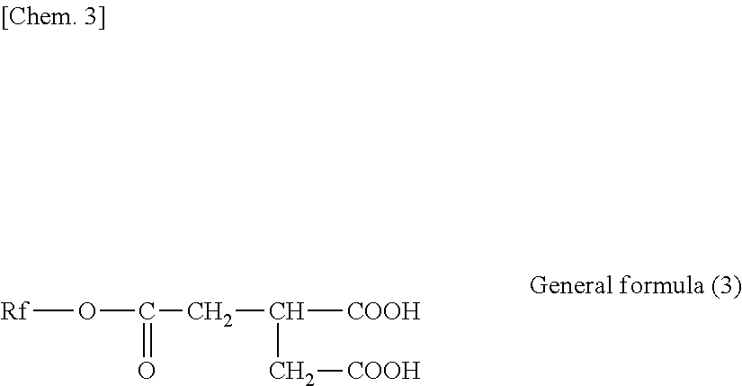
(In the expression, Rf is an unsubstituted or substituted and saturated or unsaturated fluorine-containing hydrocarbon group or hydrocarbon group.)

(In the general formula (4), 1 is an integer selected from the range of 8 to 30, more desirably 12 to 20.)

(In the general formula (5), m and n are integers respectively selected from the following ranges: m=2 to 20 and n=3 to 18, more desirably m=4 to 13 and n=3 to 10.)
(In the general formula (6), n1+n2=n and m1+m2=m hold.)
- CF3(CF2)7(CH2)10COOCH(COOH)CH2COOH
- CF3(CF2)3(CH2)10COOCH(COOH)CH2COOH
- C17H35COOCH(COOH)CH2COOH
- CF3(CF2)7(CH2)2OCOCH2CH(C18H37)COOCH(COOH)CH2COOH
- CF3(CF2)7COOCH(COOH)CH2COOH
- CHF2(CF2)7COOCH(COOH)CH2COOH
- CF3(CF2)7(CH2)2OCOCH2CH(COOH)CH2COOH
- CF3(CF2)7(CH2)6OCOCH2CH(COOH)CH2COOH
- CF3(CF2)7(CH2)11OCOCH2CH(COOH)CH2COOH
- CF3(CF2)3(CH2)6OCOCH2CH(COOH)CH2COOH
- C18H37OCOCH2CH(COOH)CH2COOH
- CF3(CF2)7(CH2)4COOCH(COOH)CH2COOH
- CF3(CF2)3(CH2)4COOCH(COOH)CH2COOH
- CF3(CF2)3(CH2)7COOCH(COOH)CH2COOH
- CF3(CF2)9(CH2)10COOCH(COOH)CH2COOH
- CF3(CF2)7(CH2)12COOCH(COOH)CH2COOH
- CF3(CF2)5(CH2)10COOCH(COOH)CH2COOH
- CF3(CF2)7CH(C9H19)CH2CH═CH(CH2)7COOCH(COOH)CH2COOH
- CF3(CF2)7CH(C6H13)(CH2)7COOCH(COOH)CH2COOH
- CH3(CH2)3(CH2CH2CH(CH2CH2(CF2)9CF3))2(CH2)7COOCH(COOH)CH2COOH.
(Number of Projections Having Height of 7.5 nm or More)
Threshold(7.5) (nm)=Ave surface(nm)+7.5 (nm) (3)
Threshold(5) (nm)=Ave_surface(nm)+5 (nm) (4)
Threshold(10) (nm)=Ave_surface (nm)+10 (nm) (5)
Threshold(15) (nm)=Ave_surface(nm)+15 (nm) (6)
Threshold(20) (nm)=Ave_surface(nm)+20 (nm) (7)
(Evaluation of Recording and Reproducing Properties)
| TABLE 1 | |
| Presence/absence of correlation | |
| Number of projections- | ||
| Height of | recording and reproducing | Number of projections- |
| projections | properties | high- |
| 5 nm or more | absent | absent |
| 7.5 nm or more | absent | present |
| 10 nm or more | absent | absent |
| 15 nm or more | present | absent |
| 20 nm or more | absent | absent |
| TABLE 2 | ||||
| Recording surface | Recording | |||
| Presence/ | and | ||||||
| Type of | absence | Peak | Peak | reproducing | Frictional | ||
| base | of uneven | SRa | (15) | (7.5) | properites | force | |
| substance | layer | [nm] | [number] | [number ] | [dB] | [%] | |
| Example 1 | Film A | Absent | 1.8 | 24 | 670 | 2.9 | 37 |
| Example 2 | Film A | Absent | 1.7 | 14 | 510 | 3.6 | 33 |
| Example 3 | Film A | Absent | 1.7 | 4 | 310 | 4.2 | 37 |
| Example 4 | Film A | Absent | 1.7 | 2 | 320 | 4.7 | 40 |
| Example 5 | Film B | Absent | 1.6 | 27 | 330 | 2.7 | 45 |
| Example 6 | Film B | Absent | 1.5 | 24 | 450 | 2.7 | 43 |
| Example 7 | Film B | Absent | 1.4 | 11 | 320 | 3.7 | 47 |
| Example 8 | Film B | Absent | 1.4 | 8 | 340 | 4.3 | 57 |
| Example 9 | Film B | Absent | 2.8 | 76 | 2540 | 1.4 | 12 |
| Example 10 | Film B | Present | 2.1 | 0 | 670 | 4.5 | 60 |
| Example 11 | Film B | Present | 2.9 | 79 | 2310 | 1.2 | 12 |
| Example 12 | Film B | Absent | 1.6 | 2 | 310 | 3.0 | 35 |
| Comparative | Film B | Absent | 1.5 | 105 | 255 | 0.0 | 100 |
| Example 1 | |||||||
| Comparative | Film B | Absent | 1.4 | 2 | 120 | 4.2 | 700 |
| Example 2 | |||||||
| Comparative | Film B | Absent | 1.4 | 2 | 110 | 4.6 | 380 |
| Example 3 | |||||||
| Comparative | Film B | Absent | 1.4 | 3 | 220 | 4.2 | 550 |
| Example 4 | |||||||
| Comparative | Film B | Absent | 1.5 | 0 | 130 | 5.0 | 117 |
| Example 5 | |||||||
| Comparative | Film B | Present | 2.3 | 150 | 1410 | −1.6 | 13 |
| Example 6 | |||||||
| Comparative | Film B | Present | 3.2 | 99 | 2800 | −1.5 | 11 |
| Example 7 | |||||||
-
- a foundation layer, and
- a seed layer provided between the foundation layer and the base substance.
(11)
(CoxPtyCr100-x-y)100-z-(SiO2)z
(where x, y, and z are values in the range of 69≤x≤72, 12≤y≤16, and 9≤z≤12, respectively).
- 11 base substance
- 12, 12A, 12B, 40 crystal control layer
- 13 magnetic layer
- 14 protective layer
- 15 lubricant layer
- 16 backcoat layer
- 17 uneven layer
- 18, 21, 41 seed layer
- 19 SUL
- 19A APC-SUL
- 19 a, 19 c soft magnetic layer
- 19 b, 42 intermediate layer
- 22 foundation layer
- 31 film formation chamber
- 32 drum
- 33 a, 33 b, 33 c cathodes
- 34 supply reel
- 35 take-up reel
Claims (21)
(CoxPtyCr100-x-y)100-z—(SiO2)z
Applications Claiming Priority (3)
| Application Number | Priority Date | Filing Date | Title |
|---|---|---|---|
| JP2015-100859 | 2015-05-18 | ||
| JP2015100859 | 2015-05-18 | ||
| PCT/JP2016/002337 WO2016185695A1 (en) | 2015-05-18 | 2016-05-12 | Magnetic recording medium |
Publications (2)
| Publication Number | Publication Date |
|---|---|
| US20180137887A1 US20180137887A1 (en) | 2018-05-17 |
| US10580447B2 true US10580447B2 (en) | 2020-03-03 |
Family
ID=57319797
Family Applications (1)
| Application Number | Title | Priority Date | Filing Date |
|---|---|---|---|
| US15/573,374 Active 2036-10-29 US10580447B2 (en) | 2015-05-18 | 2016-05-12 | Magnetic recording medium with controlled surface characteristics |
Country Status (4)
| Country | Link |
|---|---|
| US (1) | US10580447B2 (en) |
| EP (1) | EP3300080B1 (en) |
| JP (1) | JP6597775B2 (en) |
| WO (1) | WO2016185695A1 (en) |
Cited By (2)
| Publication number | Priority date | Publication date | Assignee | Title |
|---|---|---|---|---|
| US11437066B2 (en) * | 2018-03-30 | 2022-09-06 | Sony Corporation | Magnetic recording tape and magnetic recording tape cartridge |
| US11621020B2 (en) * | 2017-04-07 | 2023-04-04 | Sony Corporation | Magnetic recording medium |
Families Citing this family (89)
| Publication number | Priority date | Publication date | Assignee | Title |
|---|---|---|---|---|
| JP6316248B2 (en) | 2015-08-21 | 2018-04-25 | 富士フイルム株式会社 | Magnetic tape and manufacturing method thereof |
| US10540996B2 (en) | 2015-09-30 | 2020-01-21 | Fujifilm Corporation | Magnetic tape having characterized magnetic layer and magnetic tape device |
| JP6825573B2 (en) * | 2015-11-17 | 2021-02-03 | ソニー株式会社 | Magnetic recording medium |
| US10403319B2 (en) | 2015-12-16 | 2019-09-03 | Fujifilm Corporation | Magnetic tape having characterized magnetic layer, tape cartridge, and recording and reproducing device |
| JP6552402B2 (en) | 2015-12-16 | 2019-07-31 | 富士フイルム株式会社 | Magnetic tape, magnetic tape cartridge, magnetic recording / reproducing apparatus, and method of manufacturing magnetic tape |
| JP6430927B2 (en) | 2015-12-25 | 2018-11-28 | 富士フイルム株式会社 | Magnetic tape and manufacturing method thereof |
| JP6465823B2 (en) | 2016-02-03 | 2019-02-06 | 富士フイルム株式会社 | Magnetic tape and manufacturing method thereof |
| JP6427127B2 (en) | 2016-02-03 | 2018-11-21 | 富士フイルム株式会社 | Magnetic tape and method of manufacturing the same |
| JP6472764B2 (en) | 2016-02-29 | 2019-02-20 | 富士フイルム株式会社 | Magnetic tape |
| JP6474748B2 (en) | 2016-02-29 | 2019-02-27 | 富士フイルム株式会社 | Magnetic tape |
| JP6467366B2 (en) | 2016-02-29 | 2019-02-13 | 富士フイルム株式会社 | Magnetic tape |
| JP6556096B2 (en) | 2016-06-10 | 2019-08-07 | 富士フイルム株式会社 | Magnetic tape and magnetic tape device |
| JP6534637B2 (en) | 2016-06-13 | 2019-06-26 | 富士フイルム株式会社 | Magnetic tape and magnetic tape device |
| JP6534969B2 (en) | 2016-06-22 | 2019-06-26 | 富士フイルム株式会社 | Magnetic tape |
| JP6556100B2 (en) | 2016-06-22 | 2019-08-07 | 富士フイルム株式会社 | Magnetic tape |
| JP6549528B2 (en) | 2016-06-23 | 2019-07-24 | 富士フイルム株式会社 | Magnetic tape and magnetic tape device |
| JP6496277B2 (en) | 2016-06-23 | 2019-04-03 | 富士フイルム株式会社 | Magnetic tape |
| JP6556102B2 (en) | 2016-06-23 | 2019-08-07 | 富士フイルム株式会社 | Magnetic tape and magnetic tape device |
| JP6549529B2 (en) | 2016-06-23 | 2019-07-24 | 富士フイルム株式会社 | Magnetic tape and magnetic tape device |
| JP6498154B2 (en) | 2016-06-23 | 2019-04-10 | 富士フイルム株式会社 | Magnetic tape and magnetic tape device |
| JP6556101B2 (en) | 2016-06-23 | 2019-08-07 | 富士フイルム株式会社 | Magnetic tape and magnetic tape device |
| JP6717684B2 (en) | 2016-06-23 | 2020-07-01 | 富士フイルム株式会社 | Magnetic tape and magnetic tape device |
| JP6507126B2 (en) | 2016-06-23 | 2019-04-24 | 富士フイルム株式会社 | Magnetic tape and magnetic tape device |
| JP6529933B2 (en) | 2016-06-24 | 2019-06-12 | 富士フイルム株式会社 | Magnetic tape |
| JP6556107B2 (en) | 2016-08-31 | 2019-08-07 | 富士フイルム株式会社 | Magnetic tape |
| JP6552467B2 (en) | 2016-08-31 | 2019-07-31 | 富士フイルム株式会社 | Magnetic tape |
| JP6585570B2 (en) | 2016-09-16 | 2019-10-02 | 富士フイルム株式会社 | Magnetic recording medium and method for manufacturing the same |
| JP6684203B2 (en) | 2016-12-27 | 2020-04-22 | 富士フイルム株式会社 | Magnetic tape device and magnetic reproducing method |
| JP6588002B2 (en) | 2016-12-27 | 2019-10-09 | 富士フイルム株式会社 | Magnetic tape device and magnetic reproducing method |
| JP6701072B2 (en) | 2016-12-27 | 2020-05-27 | 富士フイルム株式会社 | Magnetic tape device and head tracking servo method |
| JP2018106778A (en) | 2016-12-27 | 2018-07-05 | 富士フイルム株式会社 | Magnetic tape device and magnetic reproducing method |
| JP6685248B2 (en) | 2017-02-20 | 2020-04-22 | 富士フイルム株式会社 | Magnetic tape |
| JP6684239B2 (en) | 2017-02-20 | 2020-04-22 | 富士フイルム株式会社 | Magnetic tape |
| JP6684237B2 (en) | 2017-02-20 | 2020-04-22 | 富士フイルム株式会社 | Magnetic tape device and head tracking servo method |
| JP6689223B2 (en) | 2017-02-20 | 2020-04-28 | 富士フイルム株式会社 | Magnetic tape |
| JP6637456B2 (en) | 2017-02-20 | 2020-01-29 | 富士フイルム株式会社 | Magnetic tape |
| JP6684236B2 (en) * | 2017-02-20 | 2020-04-22 | 富士フイルム株式会社 | Magnetic tape device and magnetic reproducing method |
| JP6602805B2 (en) | 2017-02-20 | 2019-11-06 | 富士フイルム株式会社 | Magnetic tape |
| JP6684234B2 (en) * | 2017-02-20 | 2020-04-22 | 富士フイルム株式会社 | Magnetic tape device and magnetic reproducing method |
| JP6649297B2 (en) | 2017-02-20 | 2020-02-19 | 富士フイルム株式会社 | Magnetic tape device and magnetic reproducing method |
| JP6602806B2 (en) | 2017-02-20 | 2019-11-06 | 富士フイルム株式会社 | Magnetic tape |
| JP6649298B2 (en) | 2017-02-20 | 2020-02-19 | 富士フイルム株式会社 | Magnetic tape device and head tracking servo method |
| JP6684238B2 (en) | 2017-02-20 | 2020-04-22 | 富士フイルム株式会社 | Magnetic tape |
| JP6684235B2 (en) * | 2017-02-20 | 2020-04-22 | 富士フイルム株式会社 | Magnetic tape device and head tracking servo method |
| JP6689222B2 (en) | 2017-02-20 | 2020-04-28 | 富士フイルム株式会社 | Magnetic tape |
| JP6649313B2 (en) | 2017-03-29 | 2020-02-19 | 富士フイルム株式会社 | Magnetic tape device and magnetic reproducing method |
| JP6649312B2 (en) | 2017-03-29 | 2020-02-19 | 富士フイルム株式会社 | Magnetic tape device and magnetic reproducing method |
| JP6626031B2 (en) | 2017-03-29 | 2019-12-25 | 富士フイルム株式会社 | Magnetic tape device and magnetic reproducing method |
| JP6632562B2 (en) | 2017-03-29 | 2020-01-22 | 富士フイルム株式会社 | Magnetic tape |
| JP6694844B2 (en) | 2017-03-29 | 2020-05-20 | 富士フイルム株式会社 | Magnetic tape device, magnetic reproducing method and head tracking servo method |
| JP6615814B2 (en) | 2017-03-29 | 2019-12-04 | 富士フイルム株式会社 | Magnetic tape device and head tracking servo method |
| JP6615815B2 (en) | 2017-03-29 | 2019-12-04 | 富士フイルム株式会社 | Magnetic tape device and head tracking servo method |
| JP6649314B2 (en) | 2017-03-29 | 2020-02-19 | 富士フイルム株式会社 | Magnetic tape device and head tracking servo method |
| JP6626032B2 (en) | 2017-03-29 | 2019-12-25 | 富士フイルム株式会社 | Magnetic tape device and magnetic reproducing method |
| JP6660336B2 (en) | 2017-03-29 | 2020-03-11 | 富士フイルム株式会社 | Magnetic tape device and head tracking servo method |
| JP6632561B2 (en) | 2017-03-29 | 2020-01-22 | 富士フイルム株式会社 | Magnetic tape device and magnetic reproducing method |
| JP6723198B2 (en) | 2017-06-23 | 2020-07-15 | 富士フイルム株式会社 | Magnetic tape and magnetic tape device |
| JP6691512B2 (en) | 2017-06-23 | 2020-04-28 | 富士フイルム株式会社 | Magnetic recording medium |
| JP6707061B2 (en) | 2017-07-19 | 2020-06-10 | 富士フイルム株式会社 | Magnetic recording medium |
| JP6717785B2 (en) | 2017-07-19 | 2020-07-08 | 富士フイルム株式会社 | Magnetic recording medium |
| JP6723202B2 (en) | 2017-07-19 | 2020-07-15 | 富士フイルム株式会社 | Magnetic tape |
| US10839849B2 (en) | 2017-07-19 | 2020-11-17 | Fujifilm Corporation | Magnetic recording medium having characterized magnetic layer |
| JP6714548B2 (en) | 2017-07-19 | 2020-06-24 | 富士フイルム株式会社 | Magnetic tape and magnetic tape device |
| JP6678135B2 (en) | 2017-07-19 | 2020-04-08 | 富士フイルム株式会社 | Magnetic recording media |
| JP6717786B2 (en) | 2017-07-19 | 2020-07-08 | 富士フイルム株式会社 | Magnetic tape and magnetic tape device |
| US10854230B2 (en) | 2017-07-19 | 2020-12-01 | Fujifilm Corporation | Magnetic tape having characterized magnetic layer |
| JP6707060B2 (en) | 2017-07-19 | 2020-06-10 | 富士フイルム株式会社 | Magnetic tape |
| JP6717787B2 (en) | 2017-07-19 | 2020-07-08 | 富士フイルム株式会社 | Magnetic tape and magnetic tape device |
| JP6723203B2 (en) | 2017-07-19 | 2020-07-15 | 富士フイルム株式会社 | Magnetic tape |
| US10854227B2 (en) | 2017-07-19 | 2020-12-01 | Fujifilm Corporation | Magnetic recording medium having characterized magnetic layer |
| US10854234B2 (en) | 2017-09-29 | 2020-12-01 | Fujifilm Corporation | Magnetic recording medium having characterized magnetic layer and magnetic recording and reproducing device |
| US10978105B2 (en) | 2017-09-29 | 2021-04-13 | Fujifilm Corporation | Magnetic recording medium having characterized magnetic layer and magnetic recording and reproducing device |
| US10515657B2 (en) | 2017-09-29 | 2019-12-24 | Fujifilm Corporation | Magnetic tape having characterized magnetic layer and magnetic recording and reproducing device |
| US10854231B2 (en) | 2017-09-29 | 2020-12-01 | Fujifilm Corporation | Magnetic recording medium having characterized magnetic layer and magnetic recording and reproducing device |
| US10854233B2 (en) | 2017-09-29 | 2020-12-01 | Fujifilm Corporation | Magnetic recording medium having characterized magnetic layer and magnetic recording and reproducing device |
| CN111164685B (en) | 2017-09-29 | 2021-07-23 | 富士胶片株式会社 | Magnetic tape and magnetic recording and playback devices |
| JP6884220B2 (en) | 2017-09-29 | 2021-06-09 | 富士フイルム株式会社 | Magnetic tape and magnetic recording / playback device |
| US11361793B2 (en) | 2018-03-23 | 2022-06-14 | Fujifilm Corporation | Magnetic tape having characterized magnetic layer and magnetic recording and reproducing device |
| US11361792B2 (en) | 2018-03-23 | 2022-06-14 | Fujifilm Corporation | Magnetic tape having characterized magnetic layer and magnetic recording and reproducing device |
| US11514943B2 (en) | 2018-03-23 | 2022-11-29 | Fujifilm Corporation | Magnetic tape and magnetic tape device |
| US11514944B2 (en) | 2018-03-23 | 2022-11-29 | Fujifilm Corporation | Magnetic tape and magnetic tape device |
| JP6830931B2 (en) | 2018-07-27 | 2021-02-17 | 富士フイルム株式会社 | Magnetic tapes, magnetic tape cartridges and magnetic tape devices |
| JP6784738B2 (en) | 2018-10-22 | 2020-11-11 | 富士フイルム株式会社 | Magnetic tapes, magnetic tape cartridges and magnetic tape devices |
| JP7042737B2 (en) | 2018-12-28 | 2022-03-28 | 富士フイルム株式会社 | Magnetic tape, magnetic tape cartridge and magnetic tape device |
| JP6830945B2 (en) | 2018-12-28 | 2021-02-17 | 富士フイルム株式会社 | Magnetic tapes, magnetic tape cartridges and magnetic tape devices |
| JP7003073B2 (en) | 2019-01-31 | 2022-01-20 | 富士フイルム株式会社 | Magnetic tapes, magnetic tape cartridges and magnetic tape devices |
| JP6590102B1 (en) | 2019-04-26 | 2019-10-16 | ソニー株式会社 | Magnetic recording cartridge |
| JP6778804B1 (en) | 2019-09-17 | 2020-11-04 | 富士フイルム株式会社 | Magnetic recording medium and magnetic recording / playback device |
| WO2021149680A1 (en) | 2020-01-21 | 2021-07-29 | ソニーグループ株式会社 | Magnetic recording medium and cartridge |
Citations (13)
| Publication number | Priority date | Publication date | Assignee | Title |
|---|---|---|---|---|
| US6251496B1 (en) * | 1997-12-16 | 2001-06-26 | Matsushita Electric Industrial Co., Ltd. | Magnetic recording medium method and apparatus for producing the same |
| US6372367B1 (en) * | 1998-05-12 | 2002-04-16 | Hitachi, Ltd. | Magnetic recording medium, method for producing the same and magnetic recording apparatus using the same |
| US6395412B1 (en) * | 1999-05-24 | 2002-05-28 | Hitachi, Ltd. | Magnetic recording media, manufacturing method for thereof and apparatus for using the media |
| US6468628B2 (en) * | 2000-01-18 | 2002-10-22 | Toray Industries, Inc. | Magnetic recording medium |
| US6652953B2 (en) * | 1998-07-22 | 2003-11-25 | Fuji Photo Film Co., Ltd. | Magnetic recording medium |
| JP2005196885A (en) | 2004-01-08 | 2005-07-21 | Sony Corp | Magnetic recording medium |
| JP2005293787A (en) | 2004-04-05 | 2005-10-20 | Fuji Photo Film Co Ltd | Magnetic recording medium |
| US7026064B1 (en) * | 2000-03-07 | 2006-04-11 | Toray Industries, Inc. | Polyester film and method for producing the same |
| US20060088735A1 (en) * | 2004-10-27 | 2006-04-27 | Hitachi Global Storage Technologies Netherlands B.V. | Method for manufacturing magnetic disk using cleaning tape |
| US20070042227A1 (en) * | 2003-09-25 | 2007-02-22 | Takeshi Iwasaki | Perpendicular magnetic recording medium and magnetic recording/reproducing apparatus |
| JP2007250059A (en) | 2006-03-15 | 2007-09-27 | Fuji Electric Device Technology Co Ltd | Magnetic recording medium and method for manufacturing the same |
| US20080020243A1 (en) * | 2006-06-30 | 2008-01-24 | Fujifilm Corporation | Carbonic acid ester, production process therefor, and magnetic recording medium |
| US20130314815A1 (en) * | 2012-05-23 | 2013-11-28 | Wd Media, Inc. | Underlayers for heat assisted magnetic recording (hamr) media |
Family Cites Families (7)
| Publication number | Priority date | Publication date | Assignee | Title |
|---|---|---|---|---|
| EP0642120B1 (en) * | 1993-09-06 | 1998-07-08 | Matsushita Electric Industrial Co., Ltd. | Magnetic recording medium |
| JP2002216340A (en) * | 2000-06-22 | 2002-08-02 | Sony Corp | Magnetic recording media |
| SG108872A1 (en) * | 2001-10-24 | 2005-02-28 | Toda Kogyo Corp | Perpendicular magnetic recording medium |
| SG118182A1 (en) * | 2002-03-19 | 2006-01-27 | Fuji Electric Co Ltd | Method for producing a magnetic recording medium and a magnetic recording medium produced by the method |
| JP2003317232A (en) * | 2002-04-19 | 2003-11-07 | Fuji Photo Film Co Ltd | Magnetic recording medium |
| JP4540288B2 (en) * | 2002-06-17 | 2010-09-08 | 富士電機デバイステクノロジー株式会社 | Perpendicular magnetic recording medium and manufacturing method thereof |
| JP6307879B2 (en) * | 2013-05-17 | 2018-04-11 | ソニー株式会社 | Magnetic recording medium and method for manufacturing the same |
-
2016
- 2016-05-12 US US15/573,374 patent/US10580447B2/en active Active
- 2016-05-12 JP JP2017518752A patent/JP6597775B2/en active Active
- 2016-05-12 WO PCT/JP2016/002337 patent/WO2016185695A1/en not_active Ceased
- 2016-05-12 EP EP16796091.3A patent/EP3300080B1/en active Active
Patent Citations (13)
| Publication number | Priority date | Publication date | Assignee | Title |
|---|---|---|---|---|
| US6251496B1 (en) * | 1997-12-16 | 2001-06-26 | Matsushita Electric Industrial Co., Ltd. | Magnetic recording medium method and apparatus for producing the same |
| US6372367B1 (en) * | 1998-05-12 | 2002-04-16 | Hitachi, Ltd. | Magnetic recording medium, method for producing the same and magnetic recording apparatus using the same |
| US6652953B2 (en) * | 1998-07-22 | 2003-11-25 | Fuji Photo Film Co., Ltd. | Magnetic recording medium |
| US6395412B1 (en) * | 1999-05-24 | 2002-05-28 | Hitachi, Ltd. | Magnetic recording media, manufacturing method for thereof and apparatus for using the media |
| US6468628B2 (en) * | 2000-01-18 | 2002-10-22 | Toray Industries, Inc. | Magnetic recording medium |
| US7026064B1 (en) * | 2000-03-07 | 2006-04-11 | Toray Industries, Inc. | Polyester film and method for producing the same |
| US20070042227A1 (en) * | 2003-09-25 | 2007-02-22 | Takeshi Iwasaki | Perpendicular magnetic recording medium and magnetic recording/reproducing apparatus |
| JP2005196885A (en) | 2004-01-08 | 2005-07-21 | Sony Corp | Magnetic recording medium |
| JP2005293787A (en) | 2004-04-05 | 2005-10-20 | Fuji Photo Film Co Ltd | Magnetic recording medium |
| US20060088735A1 (en) * | 2004-10-27 | 2006-04-27 | Hitachi Global Storage Technologies Netherlands B.V. | Method for manufacturing magnetic disk using cleaning tape |
| JP2007250059A (en) | 2006-03-15 | 2007-09-27 | Fuji Electric Device Technology Co Ltd | Magnetic recording medium and method for manufacturing the same |
| US20080020243A1 (en) * | 2006-06-30 | 2008-01-24 | Fujifilm Corporation | Carbonic acid ester, production process therefor, and magnetic recording medium |
| US20130314815A1 (en) * | 2012-05-23 | 2013-11-28 | Wd Media, Inc. | Underlayers for heat assisted magnetic recording (hamr) media |
Non-Patent Citations (2)
| Title |
|---|
| International Search Report (with English translation) dated Aug. 2, 2016 in corresponding international application No. 002337 (5 pages). |
| Written Opinion dated Aug. 2, 2016 in corresponding international application No. PCT/JP2016/002337 (6 pages). |
Cited By (2)
| Publication number | Priority date | Publication date | Assignee | Title |
|---|---|---|---|---|
| US11621020B2 (en) * | 2017-04-07 | 2023-04-04 | Sony Corporation | Magnetic recording medium |
| US11437066B2 (en) * | 2018-03-30 | 2022-09-06 | Sony Corporation | Magnetic recording tape and magnetic recording tape cartridge |
Also Published As
| Publication number | Publication date |
|---|---|
| JP6597775B2 (en) | 2019-10-30 |
| JPWO2016185695A1 (en) | 2018-03-08 |
| EP3300080A1 (en) | 2018-03-28 |
| US20180137887A1 (en) | 2018-05-17 |
| EP3300080B1 (en) | 2020-02-05 |
| WO2016185695A1 (en) | 2016-11-24 |
| EP3300080A4 (en) | 2018-10-03 |
Similar Documents
| Publication | Publication Date | Title |
|---|---|---|
| US10580447B2 (en) | Magnetic recording medium with controlled surface characteristics | |
| JP6753548B1 (en) | Magnetic recording medium and cartridge | |
| US10984833B2 (en) | Magnetic recording cartridge | |
| US11521650B2 (en) | Magnetic recording medium having a controlled dimensional variation | |
| JP6590103B1 (en) | Magnetic recording medium | |
| US11315594B2 (en) | Magnetic recording medium having controlled dimensional variation | |
| US11302353B2 (en) | Magnetic recording medium having controlled dimensional variation | |
| JP6662488B1 (en) | Magnetic recording cartridge | |
| JP6677340B1 (en) | Magnetic recording media | |
| JP6662487B1 (en) | Magnetic recording media | |
| JP6733798B1 (en) | Magnetic recording medium | |
| JP6677339B1 (en) | Magnetic recording media | |
| JP2020166919A (en) | Magnetic recording medium |
Legal Events
| Date | Code | Title | Description |
|---|---|---|---|
| FEPP | Fee payment procedure |
Free format text: ENTITY STATUS SET TO UNDISCOUNTED (ORIGINAL EVENT CODE: BIG.); ENTITY STATUS OF PATENT OWNER: LARGE ENTITY |
|
| STPP | Information on status: patent application and granting procedure in general |
Free format text: DOCKETED NEW CASE - READY FOR EXAMINATION |
|
| STPP | Information on status: patent application and granting procedure in general |
Free format text: NON FINAL ACTION MAILED |
|
| STPP | Information on status: patent application and granting procedure in general |
Free format text: RESPONSE TO NON-FINAL OFFICE ACTION ENTERED AND FORWARDED TO EXAMINER |
|
| STPP | Information on status: patent application and granting procedure in general |
Free format text: NOTICE OF ALLOWANCE MAILED -- APPLICATION RECEIVED IN OFFICE OF PUBLICATIONS |
|
| AS | Assignment |
Owner name: SONY CORPORATION, JAPAN Free format text: ASSIGNMENT OF ASSIGNORS INTEREST;ASSIGNORS:SEKIGUCHI, NOBORU;OZAKI, TOMOE;ENDO, TETSUO;AND OTHERS;SIGNING DATES FROM 20170919 TO 20170920;REEL/FRAME:050870/0618 |
|
| STPP | Information on status: patent application and granting procedure in general |
Free format text: PUBLICATIONS -- ISSUE FEE PAYMENT VERIFIED |
|
| STCF | Information on status: patent grant |
Free format text: PATENTED CASE |
|
| MAFP | Maintenance fee payment |
Free format text: PAYMENT OF MAINTENANCE FEE, 4TH YEAR, LARGE ENTITY (ORIGINAL EVENT CODE: M1551); ENTITY STATUS OF PATENT OWNER: LARGE ENTITY Year of fee payment: 4 |