US10569788B2 - Automatic driving control apparatus - Google Patents
Automatic driving control apparatus Download PDFInfo
- Publication number
- US10569788B2 US10569788B2 US15/814,000 US201715814000A US10569788B2 US 10569788 B2 US10569788 B2 US 10569788B2 US 201715814000 A US201715814000 A US 201715814000A US 10569788 B2 US10569788 B2 US 10569788B2
- Authority
- US
- United States
- Prior art keywords
- vehicle
- tollgate
- road
- automatic driving
- outside environment
- Prior art date
- Legal status (The legal status is an assumption and is not a legal conclusion. Google has not performed a legal analysis and makes no representation as to the accuracy of the status listed.)
- Active, expires
Links
- 238000013459 approach Methods 0.000 claims abstract description 7
- 239000003550 marker Substances 0.000 claims description 8
- 230000007423 decrease Effects 0.000 claims description 6
- 238000013500 data storage Methods 0.000 claims 1
- 230000007704 transition Effects 0.000 abstract description 11
- 238000000034 method Methods 0.000 description 33
- 230000008569 process Effects 0.000 description 33
- 238000005516 engineering process Methods 0.000 description 9
- 238000001514 detection method Methods 0.000 description 6
- 230000004048 modification Effects 0.000 description 6
- 238000012986 modification Methods 0.000 description 6
- 239000004065 semiconductor Substances 0.000 description 3
- 230000004075 alteration Effects 0.000 description 2
- 230000006870 function Effects 0.000 description 2
- 238000012545 processing Methods 0.000 description 2
- 238000004364 calculation method Methods 0.000 description 1
- 238000004891 communication Methods 0.000 description 1
- 230000000052 comparative effect Effects 0.000 description 1
- 238000010586 diagram Methods 0.000 description 1
- 238000004519 manufacturing process Methods 0.000 description 1
- 230000003287 optical effect Effects 0.000 description 1
- 230000003068 static effect Effects 0.000 description 1
- 230000002123 temporal effect Effects 0.000 description 1
Images


Classifications
-
- B—PERFORMING OPERATIONS; TRANSPORTING
- B60—VEHICLES IN GENERAL
- B60W—CONJOINT CONTROL OF VEHICLE SUB-UNITS OF DIFFERENT TYPE OR DIFFERENT FUNCTION; CONTROL SYSTEMS SPECIALLY ADAPTED FOR HYBRID VEHICLES; ROAD VEHICLE DRIVE CONTROL SYSTEMS FOR PURPOSES NOT RELATED TO THE CONTROL OF A PARTICULAR SUB-UNIT
- B60W30/00—Purposes of road vehicle drive control systems not related to the control of a particular sub-unit, e.g. of systems using conjoint control of vehicle sub-units, or advanced driver assistance systems for ensuring comfort, stability and safety or drive control systems for propelling or retarding the vehicle
- B60W30/18—Propelling the vehicle
- B60W30/182—Selecting between different operative modes, e.g. comfort and performance modes
-
- B—PERFORMING OPERATIONS; TRANSPORTING
- B60—VEHICLES IN GENERAL
- B60W—CONJOINT CONTROL OF VEHICLE SUB-UNITS OF DIFFERENT TYPE OR DIFFERENT FUNCTION; CONTROL SYSTEMS SPECIALLY ADAPTED FOR HYBRID VEHICLES; ROAD VEHICLE DRIVE CONTROL SYSTEMS FOR PURPOSES NOT RELATED TO THE CONTROL OF A PARTICULAR SUB-UNIT
- B60W50/00—Details of control systems for road vehicle drive control not related to the control of a particular sub-unit, e.g. process diagnostic or vehicle driver interfaces
- B60W50/08—Interaction between the driver and the control system
- B60W50/082—Selecting or switching between different modes of propelling
-
- B—PERFORMING OPERATIONS; TRANSPORTING
- B60—VEHICLES IN GENERAL
- B60W—CONJOINT CONTROL OF VEHICLE SUB-UNITS OF DIFFERENT TYPE OR DIFFERENT FUNCTION; CONTROL SYSTEMS SPECIALLY ADAPTED FOR HYBRID VEHICLES; ROAD VEHICLE DRIVE CONTROL SYSTEMS FOR PURPOSES NOT RELATED TO THE CONTROL OF A PARTICULAR SUB-UNIT
- B60W10/00—Conjoint control of vehicle sub-units of different type or different function
- B60W10/20—Conjoint control of vehicle sub-units of different type or different function including control of steering systems
-
- B—PERFORMING OPERATIONS; TRANSPORTING
- B60—VEHICLES IN GENERAL
- B60W—CONJOINT CONTROL OF VEHICLE SUB-UNITS OF DIFFERENT TYPE OR DIFFERENT FUNCTION; CONTROL SYSTEMS SPECIALLY ADAPTED FOR HYBRID VEHICLES; ROAD VEHICLE DRIVE CONTROL SYSTEMS FOR PURPOSES NOT RELATED TO THE CONTROL OF A PARTICULAR SUB-UNIT
- B60W30/00—Purposes of road vehicle drive control systems not related to the control of a particular sub-unit, e.g. of systems using conjoint control of vehicle sub-units, or advanced driver assistance systems for ensuring comfort, stability and safety or drive control systems for propelling or retarding the vehicle
- B60W30/10—Path keeping
-
- B—PERFORMING OPERATIONS; TRANSPORTING
- B60—VEHICLES IN GENERAL
- B60W—CONJOINT CONTROL OF VEHICLE SUB-UNITS OF DIFFERENT TYPE OR DIFFERENT FUNCTION; CONTROL SYSTEMS SPECIALLY ADAPTED FOR HYBRID VEHICLES; ROAD VEHICLE DRIVE CONTROL SYSTEMS FOR PURPOSES NOT RELATED TO THE CONTROL OF A PARTICULAR SUB-UNIT
- B60W30/00—Purposes of road vehicle drive control systems not related to the control of a particular sub-unit, e.g. of systems using conjoint control of vehicle sub-units, or advanced driver assistance systems for ensuring comfort, stability and safety or drive control systems for propelling or retarding the vehicle
- B60W30/14—Adaptive cruise control
- B60W30/143—Speed control
- B60W30/146—Speed limiting
-
- G—PHYSICS
- G05—CONTROLLING; REGULATING
- G05D—SYSTEMS FOR CONTROLLING OR REGULATING NON-ELECTRIC VARIABLES
- G05D1/00—Control of position, course or altitude of land, water, air, or space vehicles, e.g. automatic pilot
- G05D1/0055—Control of position, course or altitude of land, water, air, or space vehicles, e.g. automatic pilot with safety arrangements
- G05D1/0061—Control of position, course or altitude of land, water, air, or space vehicles, e.g. automatic pilot with safety arrangements for transition from automatic pilot to manual pilot and vice versa
-
- G—PHYSICS
- G05—CONTROLLING; REGULATING
- G05D—SYSTEMS FOR CONTROLLING OR REGULATING NON-ELECTRIC VARIABLES
- G05D1/00—Control of position, course or altitude of land, water, air, or space vehicles, e.g. automatic pilot
- G05D1/0088—Control of position, course or altitude of land, water, air, or space vehicles, e.g. automatic pilot characterized by the autonomous decision making process, e.g. artificial intelligence, predefined behaviours
-
- G—PHYSICS
- G05—CONTROLLING; REGULATING
- G05D—SYSTEMS FOR CONTROLLING OR REGULATING NON-ELECTRIC VARIABLES
- G05D1/00—Control of position, course or altitude of land, water, air, or space vehicles, e.g. automatic pilot
- G05D1/02—Control of position or course in two dimensions
- G05D1/021—Control of position or course in two dimensions specially adapted to land vehicles
- G05D1/0212—Control of position or course in two dimensions specially adapted to land vehicles with means for defining a desired trajectory
-
- G—PHYSICS
- G07—CHECKING-DEVICES
- G07B—TICKET-ISSUING APPARATUS; FARE-REGISTERING APPARATUS; FRANKING APPARATUS
- G07B15/00—Arrangements or apparatus for collecting fares, tolls or entrance fees at one or more control points
-
- G—PHYSICS
- G07—CHECKING-DEVICES
- G07B—TICKET-ISSUING APPARATUS; FARE-REGISTERING APPARATUS; FRANKING APPARATUS
- G07B15/00—Arrangements or apparatus for collecting fares, tolls or entrance fees at one or more control points
- G07B15/06—Arrangements for road pricing or congestion charging of vehicles or vehicle users, e.g. automatic toll systems
-
- B60W2550/141—
-
- B60W2550/143—
-
- B60W2550/146—
-
- B60W2550/308—
-
- B—PERFORMING OPERATIONS; TRANSPORTING
- B60—VEHICLES IN GENERAL
- B60W—CONJOINT CONTROL OF VEHICLE SUB-UNITS OF DIFFERENT TYPE OR DIFFERENT FUNCTION; CONTROL SYSTEMS SPECIALLY ADAPTED FOR HYBRID VEHICLES; ROAD VEHICLE DRIVE CONTROL SYSTEMS FOR PURPOSES NOT RELATED TO THE CONTROL OF A PARTICULAR SUB-UNIT
- B60W2552/00—Input parameters relating to infrastructure
- B60W2552/05—Type of road
-
- B—PERFORMING OPERATIONS; TRANSPORTING
- B60—VEHICLES IN GENERAL
- B60W—CONJOINT CONTROL OF VEHICLE SUB-UNITS OF DIFFERENT TYPE OR DIFFERENT FUNCTION; CONTROL SYSTEMS SPECIALLY ADAPTED FOR HYBRID VEHICLES; ROAD VEHICLE DRIVE CONTROL SYSTEMS FOR PURPOSES NOT RELATED TO THE CONTROL OF A PARTICULAR SUB-UNIT
- B60W2552/00—Input parameters relating to infrastructure
- B60W2552/10—Number of lanes
-
- B—PERFORMING OPERATIONS; TRANSPORTING
- B60—VEHICLES IN GENERAL
- B60W—CONJOINT CONTROL OF VEHICLE SUB-UNITS OF DIFFERENT TYPE OR DIFFERENT FUNCTION; CONTROL SYSTEMS SPECIALLY ADAPTED FOR HYBRID VEHICLES; ROAD VEHICLE DRIVE CONTROL SYSTEMS FOR PURPOSES NOT RELATED TO THE CONTROL OF A PARTICULAR SUB-UNIT
- B60W2552/00—Input parameters relating to infrastructure
- B60W2552/20—Road profile
-
- B—PERFORMING OPERATIONS; TRANSPORTING
- B60—VEHICLES IN GENERAL
- B60W—CONJOINT CONTROL OF VEHICLE SUB-UNITS OF DIFFERENT TYPE OR DIFFERENT FUNCTION; CONTROL SYSTEMS SPECIALLY ADAPTED FOR HYBRID VEHICLES; ROAD VEHICLE DRIVE CONTROL SYSTEMS FOR PURPOSES NOT RELATED TO THE CONTROL OF A PARTICULAR SUB-UNIT
- B60W2552/00—Input parameters relating to infrastructure
- B60W2552/30—Road curve radius
-
- B—PERFORMING OPERATIONS; TRANSPORTING
- B60—VEHICLES IN GENERAL
- B60W—CONJOINT CONTROL OF VEHICLE SUB-UNITS OF DIFFERENT TYPE OR DIFFERENT FUNCTION; CONTROL SYSTEMS SPECIALLY ADAPTED FOR HYBRID VEHICLES; ROAD VEHICLE DRIVE CONTROL SYSTEMS FOR PURPOSES NOT RELATED TO THE CONTROL OF A PARTICULAR SUB-UNIT
- B60W2552/00—Input parameters relating to infrastructure
- B60W2552/50—Barriers
-
- B—PERFORMING OPERATIONS; TRANSPORTING
- B60—VEHICLES IN GENERAL
- B60W—CONJOINT CONTROL OF VEHICLE SUB-UNITS OF DIFFERENT TYPE OR DIFFERENT FUNCTION; CONTROL SYSTEMS SPECIALLY ADAPTED FOR HYBRID VEHICLES; ROAD VEHICLE DRIVE CONTROL SYSTEMS FOR PURPOSES NOT RELATED TO THE CONTROL OF A PARTICULAR SUB-UNIT
- B60W2552/00—Input parameters relating to infrastructure
- B60W2552/53—Road markings, e.g. lane marker or crosswalk
-
- B—PERFORMING OPERATIONS; TRANSPORTING
- B60—VEHICLES IN GENERAL
- B60W—CONJOINT CONTROL OF VEHICLE SUB-UNITS OF DIFFERENT TYPE OR DIFFERENT FUNCTION; CONTROL SYSTEMS SPECIALLY ADAPTED FOR HYBRID VEHICLES; ROAD VEHICLE DRIVE CONTROL SYSTEMS FOR PURPOSES NOT RELATED TO THE CONTROL OF A PARTICULAR SUB-UNIT
- B60W2554/00—Input parameters relating to objects
- B60W2554/20—Static objects
-
- B—PERFORMING OPERATIONS; TRANSPORTING
- B60—VEHICLES IN GENERAL
- B60W—CONJOINT CONTROL OF VEHICLE SUB-UNITS OF DIFFERENT TYPE OR DIFFERENT FUNCTION; CONTROL SYSTEMS SPECIALLY ADAPTED FOR HYBRID VEHICLES; ROAD VEHICLE DRIVE CONTROL SYSTEMS FOR PURPOSES NOT RELATED TO THE CONTROL OF A PARTICULAR SUB-UNIT
- B60W2554/00—Input parameters relating to objects
- B60W2554/60—Traversable objects, e.g. speed bumps or curbs
-
- B—PERFORMING OPERATIONS; TRANSPORTING
- B60—VEHICLES IN GENERAL
- B60W—CONJOINT CONTROL OF VEHICLE SUB-UNITS OF DIFFERENT TYPE OR DIFFERENT FUNCTION; CONTROL SYSTEMS SPECIALLY ADAPTED FOR HYBRID VEHICLES; ROAD VEHICLE DRIVE CONTROL SYSTEMS FOR PURPOSES NOT RELATED TO THE CONTROL OF A PARTICULAR SUB-UNIT
- B60W2554/00—Input parameters relating to objects
- B60W2554/80—Spatial relation or speed relative to objects
- B60W2554/801—Lateral distance
-
- B—PERFORMING OPERATIONS; TRANSPORTING
- B60—VEHICLES IN GENERAL
- B60W—CONJOINT CONTROL OF VEHICLE SUB-UNITS OF DIFFERENT TYPE OR DIFFERENT FUNCTION; CONTROL SYSTEMS SPECIALLY ADAPTED FOR HYBRID VEHICLES; ROAD VEHICLE DRIVE CONTROL SYSTEMS FOR PURPOSES NOT RELATED TO THE CONTROL OF A PARTICULAR SUB-UNIT
- B60W2554/00—Input parameters relating to objects
- B60W2554/80—Spatial relation or speed relative to objects
- B60W2554/802—Longitudinal distance
-
- B—PERFORMING OPERATIONS; TRANSPORTING
- B60—VEHICLES IN GENERAL
- B60W—CONJOINT CONTROL OF VEHICLE SUB-UNITS OF DIFFERENT TYPE OR DIFFERENT FUNCTION; CONTROL SYSTEMS SPECIALLY ADAPTED FOR HYBRID VEHICLES; ROAD VEHICLE DRIVE CONTROL SYSTEMS FOR PURPOSES NOT RELATED TO THE CONTROL OF A PARTICULAR SUB-UNIT
- B60W2555/00—Input parameters relating to exterior conditions, not covered by groups B60W2552/00, B60W2554/00
-
- B—PERFORMING OPERATIONS; TRANSPORTING
- B60—VEHICLES IN GENERAL
- B60W—CONJOINT CONTROL OF VEHICLE SUB-UNITS OF DIFFERENT TYPE OR DIFFERENT FUNCTION; CONTROL SYSTEMS SPECIALLY ADAPTED FOR HYBRID VEHICLES; ROAD VEHICLE DRIVE CONTROL SYSTEMS FOR PURPOSES NOT RELATED TO THE CONTROL OF A PARTICULAR SUB-UNIT
- B60W2710/00—Output or target parameters relating to a particular sub-units
- B60W2710/20—Steering systems
-
- B—PERFORMING OPERATIONS; TRANSPORTING
- B60—VEHICLES IN GENERAL
- B60W—CONJOINT CONTROL OF VEHICLE SUB-UNITS OF DIFFERENT TYPE OR DIFFERENT FUNCTION; CONTROL SYSTEMS SPECIALLY ADAPTED FOR HYBRID VEHICLES; ROAD VEHICLE DRIVE CONTROL SYSTEMS FOR PURPOSES NOT RELATED TO THE CONTROL OF A PARTICULAR SUB-UNIT
- B60W2720/00—Output or target parameters relating to overall vehicle dynamics
- B60W2720/10—Longitudinal speed
-
- G—PHYSICS
- G05—CONTROLLING; REGULATING
- G05D—SYSTEMS FOR CONTROLLING OR REGULATING NON-ELECTRIC VARIABLES
- G05D2201/00—Application
- G05D2201/02—Control of position of land vehicles
- G05D2201/0213—Road vehicle, e.g. car or truck
Definitions
- the technology relates to an automatic driving control apparatus, for a vehicle, that is provided with an outside environment recognizer.
- JP-A No. 2016-137819 discloses an automatic driving control apparatus for a vehicle that travels on a road. Specifically, JP-A No. 2016-137819 discloses the automatic driving control apparatus that, after allowing for traveling on an expressway by an automatic driving control, deactivates an automatic driving state and performs switching from the automatic driving state to a manual driving state at a point where exiting from an interchange is performed.
- An aspect of the technology provides an automatic driving control apparatus including an outside environment recognizer, a traveling information detector, a positioning device, a map information output device, and a controller.
- the outside environment recognizer is configured to recognize an outside environment of a vehicle.
- the traveling information detector is configured to detect traveling information of the vehicle.
- the positioning device is configured to perform positioning of the vehicle.
- the map information output device is configured to store map information including information on a road shape.
- the controller executes an automatic driving control of the vehicle on the basis of one or more of a result of the recognition of the outside environment, the traveling information, a result of the positioning, and the map information.
- the controller determines, on the basis of the result of the positioning and the map information, presence or absence of a tollgate within a predetermined distance, from the vehicle, on a road on which the vehicle travels.
- the controller makes a transition in an operation mode of the vehicle from a regular traveling mode to a tollgate passing mode, on one of a condition that the presence of the tollgate is determined within the predetermined distance from the vehicle and an increase in width of the road is recognized on the basis of the result of the recognition of the outside environment, and a condition that the presence of the tollgate is determined within the predetermined distance from the vehicle and the width of the road becomes unrecognizable on the basis of the result of the recognition of the outside environment.
- the controller controls, in a first period of time, each of a traveling speed of the vehicle and a steering angle of the vehicle to thereby cause the vehicle to approach the tollgate, on the basis of one or both of the map information and position information of an object that is recognized on the basis of the result of the recognition of the outside environment.
- the first period of time is a period of time during which the operation mode of the vehicle is set to the tollgate passing mode, and a position of the tollgate is unrecognizable on the basis of the result of the recognition of the outside environment.
- the controller controls, in a second period of time, each of the traveling speed of the vehicle and the steering angle of the vehicle to thereby cause the vehicle to pass through the tollgate, on the basis of position information of the tollgate that is recognized on the basis of the result of the recognition of the outside environment.
- the second period of time is a period of time during which the operation mode of the vehicle is set to the tollgate passing mode, and the position of the tollgate is recognizable on the basis of the result of the recognition of the outside environment.
- FIG. 1 is a block diagram illustrating an example of a configuration of an automatic driving control apparatus according to one implementation of the technology.
- FIG. 2 is a flowchart describing an example of an operation of the automatic driving control apparatus illustrated in FIG. 1 .
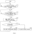
- FIG. 3 is a flowchart of an example of a tollgate passing process.
- FIG. 4 is a flowchart of an example of a tollgate approaching process.
- FIG. 5 schematically illustrates an example of a tollgate provided on a road.
- FIG. 6 is a flowchart describing an example of an operation of the automatic driving control apparatus according to a modification example.
- An automatic driving control apparatus 1 controls automatic driving of a vehicle 10 that travels on a road.
- the vehicle 10 may have a configuration that allows for variation in an output generated by a power generator, variation in braking force generated by a brake device, and variation in steering angle, and variation in any other factor, on the basis of a control signal supplied from the automatic driving control apparatus 1 .
- the power generator may include an engine and an electric motor.
- the vehicle 10 may be provided with a manual operation input device to be operated by a user of the vehicle 10 upon manual driving.
- the manual operation input device may include, for example but not limited to, a steering wheel, an accelerator pedal, a brake pedal, and a shift lever.
- the user of the vehicle 10 may be, for example but not limited to, a driver of the vehicle 10 .
- the automatic driving control apparatus 1 may include, for example but not limited to, a controller 2 , an outside environment recognizer 3 , a traveling information detector 4 , a positioning device 5 , a map information output device 6 , a notification device 7 , and a traveling controller 8 .
- the controller 2 may include, for example but not limited to, a computer provided with components such as a central processing unit (CPU), a read-only memory (ROM), a random-access memory (RAM), and an input-output unit that are coupled to a bus.
- the controller 2 may control an operation of the automatic driving control apparatus 1 on the basis of a predetermined program.
- the outside environment recognizer 3 recognizes an outside environment of the vehicle 10 .
- the outside environment recognizer 3 may detect an environment including a shape of a road on which the vehicle 10 travels, and a positional relationship between the vehicle 10 and an object present around the vehicle 10 .
- the outside environment recognizer 3 may include one or more of devices such as a camera, a millimeter-wave radar, and a lidar.
- the outside environment recognizer 3 may include a stereo camera that captures an image in a direction in which the vehicle 10 travels.
- the outside environment recognizer 3 may recognize the environment including the shape of the road and the object both ahead of the vehicle 10 , on the basis of the image captured by the stereo camera.
- the outside environment recognizer 3 may recognize the shape of the road ahead of the vehicle 10 by detecting a linear or dashed-line mark provided on the road by means of image recognition, for example.
- the linear or dashed-line mark may be so provided on the road along a traveling lane as to indicate the traveling lane, for example.
- the outside environment recognizer 3 may detect, by means of the image recognition or radar, an object that is provided along and aside of the road on which the vehicle 10 travels, and recognize the shape of the road ahead of the vehicle 10 on the basis of a result of the detection.
- Non-limiting examples of the object provided along and aside of the road may include a curb, a guardrail, and a side wall.
- the outside environment recognizer 3 may also recognize, for example but not limited to, a preceding vehicle and a tollgate that are present ahead of the vehicle 10 .
- the term “tollgate” as used herein refers to a gate-shaped facility directed to collecting a toll for a toll road. It is to be noted that the term “tollgate” as used herein encompasses a tollgate of an electronic toll collection system (ETC) that allows for payment such as advance payment and deferred payment of the toll without stopping a vehicle.
- ETC electronic toll collection system
- the traveling information detector 4 may recognize a traveling state of the vehicle 10 on the basis of a result of detection performed by a sensor with which the vehicle 10 is provided.
- the sensor may include a traveling speed sensor, a steering angle sensor, an accelerometer, and an angular accelerometer.
- the positioning device 5 may detect a current position of the vehicle 10 by means of one or more of a global positioning system (GPS), an inertial navigation system (INS), and vehicle-to-vehicle communication.
- GPS global positioning system
- INS inertial navigation system
- vehicle-to-vehicle communication may include factors such as latitude and longitude of the vehicle 10 .
- the map information output device 6 may include a storage storing map information, and output the map information.
- the map information may include, for example but not limited to, information on a shape of a road. Non-limiting examples of the information on the shape of the road may include a curvature of the road, a gradient of a longitudinal section of the road, and a state at an intersection of the road and another road.
- the map information may also include position information of the tollgate.
- the notification device 7 may include, for example but not limited to, any of a display device displaying contents such as an image and a character, a light-emitting device emitting light, a speaker generating a sound, and a vibrator generating vibration, or any combination thereof.
- the notification device 7 may allow for an output, by the automatic driving control apparatus 1 , of information to the user, such as the driver, of the vehicle 10 .
- the traveling controller 8 may perform a control that varies the output of the power generator of the vehicle 10 , a control that varies the braking force of the brake device, and any other control.
- the traveling controller 8 may include, for example but not limited to, a vehicle speed controller 8 a and a steering controller 8 b .
- the vehicle speed controller 8 a may control a traveling speed of the vehicle 10 .
- the steering controller 8 b may perform a control that varies a steering angle of the vehicle 10 .
- the automatic driving control apparatus 1 Upon execution of the automatic driving of the vehicle 10 , the automatic driving control apparatus 1 having the example configuration described above may control each of the traveling speed and the steering angle of the vehicle 10 via the traveling controller 8 on the basis of a result of the recognition by the outside environment recognizer 3 and the traveling information detector 4 . It is to be noted that a basic configuration directed to the execution of the automatic driving of the vehicle 10 may be, for example but not limited to, a known configuration which will not be described in detail herein.
- the term “regular traveling mode” refers to an operation mode in which the automatic driving control apparatus 1 causes the vehicle 10 to travel along a path that is automatically or manually set in advance.
- the automatic driving control apparatus 1 may set a target path along the shape of the road recognized by the outside environment recognizer 3 , and so control each of the traveling speed and the steering angle of the vehicle 10 that the vehicle 10 travels along the set target path.
- the processes described by the flowchart illustrated in FIG. 2 may be executed when the automatic driving of the vehicle 10 is executed in the regular traveling mode by the automatic driving control apparatus 1 . It is to be noted that the following description refers to an example case where the tollgate is compatible to the ETC that allows the vehicle 10 to pass through the tollgate without stopping the vehicle 10 .
- step S 110 the controller 2 may determine presence or absence of the tollgate ahead of the vehicle 10 on a road on which the vehicle 10 travels within a predetermined distance from the vehicle 10 .
- the controller 2 may perform the determination of the presence or the absence of the tollgate on the basis of a result of the positioning by the positioning device 5 and the map information stored in the map information output device 6 .
- step S 110 the controller 2 may continue the regular traveling mode that causes the vehicle 10 to travel along the road on which the vehicle 10 travels.
- step S 110 when the presence of the tollgate ahead of the vehicle 10 within the predetermined distance from the vehicle 10 is determined in step S 110 (step S 110 : YES), the process to be performed by the controller 2 may proceed to step S 120 .
- step S 120 the controller 2 determines whether a width, of the road on which the vehicle 10 travels, that is recognized by the outside environment recognizer 3 is increased.
- the outside environment recognizer 3 may recognize the width of the road by detecting the linear or dashed-line mark provided along the traveling lane on the basis of the image captured by the stereo camera. The foregoing detection of the linear or dashed-line mark may be performed, for example but not limited to, by means of the image recognition.
- the outside environment recognizer 3 may detect the object such as the curb, the guardrail, and the side wall that is provided along and aside of the road on which the vehicle 10 travels, and recognize the width of the road on the basis of a result of the detection.
- the outside environment recognizer 3 may perform the foregoing detection of the object, for example but not limited to, by means of the image recognition by the stereo camera or the radar.
- FIG. 5 illustrates an example of a road 20 provided with a tollgate 21 .
- the road 20 is viewed downward from a point above the road 20 , and the vehicle 10 travels in a direction from a lower part toward an upper part on the paper plane of the drawing.
- a plurality of tollgates 21 are so arranged as to allow a plurality of vehicles to pass through the tollgates 21 in parallel.
- the tollgates 21 are provided in an increased-width section 20 b of the road 20 .
- the increased-width section 20 b is a section in which the width of the road 20 is increased compared with that in a regular traveling section 20 a .
- the process in step S 120 may recognize entry of the vehicle 10 from the traveling section 20 a to the increased-width section 20 b.
- step S 120 When the increase in the width of the road on which the vehicle 10 travels is determined in step S 120 (step S 120 : YES), the process to be performed by the controller 2 may proceed to step S 200 .
- step S 200 a transition is made from the regular traveling mode to a tollgate passing mode which will be described later.
- step S 120 the controller 2 may determine whether the width, of the road on which the vehicle 10 travels, that is to be recognized by the outside environment recognizer 3 is no longer recognizable.
- step S 120 the process to be performed by the controller 2 may proceed to step S 200 .
- step S 200 the controller 2 makes the transition in the operation mode, directed to causing the vehicle 10 to travel, from the regular traveling mode to the tollgate passing mode.
- An outline of processes performed by the controller 2 in the tollgate passing mode may be as follows. That is, the controller 2 may set a target path on the basis of a position, relative to the vehicle 10 , of the tollgate that is recognized by the outside environment recognizer 3 . Further, the controller 2 may so control each of the traveling speed and the steering angle of the vehicle 10 that the vehicle 10 travels along the set target path.
- the target path may be a path along which the vehicle 10 is to pass through the tollgate.
- step S 210 the controller 2 may first determine whether the position of the tollgate is recognizable by the outside environment recognizer 3 .
- step S 210 When the position of the tollgate is recognizable by the outside environment recognizer 3 in step S 210 (step S 210 : YES), the process to be performed by the controller 2 may proceed to step S 300 .
- step S 300 the controller 2 may execute a tollgate passing process.
- FIG. 3 illustrates a flowchart of an example of the tollgate passing process.
- the tollgate passing process may include the following processes.
- the controller 2 may first determine whether the preceding vehicle that travels ahead of the vehicle 10 and toward the tollgate is recognized by the outside environment recognizer 3 .
- step S 320 the controller 2 may set, as the target path, a path along which the vehicle 10 is to follow the preceding vehicle. Further, in step S 320 , the controller 2 may so control each of the traveling speed and the steering angle of the vehicle 10 that the vehicle 10 passes through the tollgate while following the preceding vehicle. After the vehicle 10 passes through the tollgate, the controller 2 may make a transition in the operation mode directed to traveling of the vehicle 10 from the tollgate passing mode to the regular traveling mode.
- step S 310 when determination is made in step S 310 that the preceding vehicle is not recognized by the outside environment recognizer 3 (step S 310 : NO), the flow may proceed to step S 330 .
- step S 330 the controller 2 may determine whether the target path is settable that allows the vehicle 10 to pass through the tollgate recognized by the outside environment recognizer 3 .
- step S 330 When determination is made in step S 330 that the target path is settable (step S 330 : YES), the flow may proceed to step S 340 .
- step S 340 the controller 2 may so control each of the traveling speed and the steering angle of the vehicle 10 that the vehicle 10 travels along the target path that passes through the tollgate. After the vehicle 10 passes through the tollgate, the controller 2 may make the transition in the operation mode directed to traveling of the vehicle 10 from the tollgate passing mode to the regular traveling mode.
- step S 330 when determination is made in step S 330 that the target path is not settable (step S 330 : NO), the flow may proceed to step S 350 .
- step S 350 the controller 2 may calculate the position of the tollgate relative to the vehicle 10 on the basis of the result of the positioning by the positioning device 5 and the map information stored in the map information output device 6 . Further, in step S 350 , the controller 2 may set, as a virtual target path, a path along which the vehicle 10 is to pass through the tollgate, on the basis of a result of the calculation.
- step S 360 the controller 2 may so control each of the traveling speed and the steering angle of the vehicle 10 that the vehicle 10 travels along the virtual target path set in step S 350 . Thereafter, the flow may return to step S 330 .
- the controller 2 may set the virtual target path on the basis of the map information and the result of the positioning of the vehicle 10 by the positioning device 5 , and cause the vehicle 10 to travel toward the tollgate, when the target path along which the vehicle 10 is to pass through the tollgate is unsettable on the basis of the result of the recognition by the outside environment recognizer 3 . Further, the controller 2 may cause the vehicle 10 to travel toward the tollgate along the set virtual target path.
- the controller 2 may cause the vehicle 10 to travel toward the tollgate on the basis of the result of the recognition by the outside environment recognizer 3 .
- step S 210 the process to be performed by the controller 2 may proceed to step S 400 .
- step S 400 the controller 2 may execute a tollgate approaching process.
- FIG. 4 illustrates a flowchart of an example of the tollgate approaching process.
- the tollgate approaching process may include the following processes.
- the controller 2 may first determine whether the preceding vehicle that travels ahead of the vehicle 10 and toward the tollgate is recognized by the outside environment recognizer 3 .
- step S 410 When determination is made in step S 410 that the preceding vehicle is recognized by the outside environment recognizer 3 (step S 410 : YES), the flow may proceed to step S 420 .
- step S 420 the controller 2 may set, as the target path, a path along which the vehicle 10 is to follow the preceding vehicle. Further, in step S 420 , the controller 2 may so control each of the traveling speed and the steering angle of the vehicle 10 that the vehicle 10 passes through the tollgate while following the preceding vehicle. After the vehicle 10 passes through the tollgate, the controller 2 may make the transition in the operation mode directed to traveling of the vehicle 10 from the tollgate passing mode to the regular traveling mode.
- step S 410 when determination is made in step S 410 that the preceding vehicle is not recognized by the outside environment recognizer 3 (step S 410 : NO), the flow may proceed to step S 430 .
- step S 430 the controller 2 may start a control that decreases the traveling speed of the vehicle 10 in accordance with a decrease in distance from the vehicle 10 to the position, of the tollgate, that is determined on the basis of the map information.
- the execution of the process in step S 430 creates a margin for execution of processes subsequent to the process in step S 430 and thereby allows the outside environment recognizer 3 to recognize the position of the tollgate.
- step S 440 the controller 2 may determine presence or absence of an object that is disposed along an estimated path from the current position of the vehicle 10 to the position of the tollgate determined on the basis of the map information.
- the controller 2 may perform the foregoing determination by comparing the map information and the position information of the object recognized by the outside environment recognizer 3 .
- non-limiting examples of the object disposed along the estimated path may include a linear mark, a dashed-line mark, a curb, a guardrail, and a side wall that are provided on a road.
- the object disposed along the estimated path is hereinafter referred to as a marker object.
- step S 440 When the marker object is recognized by the outside environment recognizer 3 in step S 440 (step S 440 : YES), the process to be performed by the controller 2 may proceed to step S 450 .
- step S 450 the controller 2 may set the target path along the marker object, and so start the control of each of the traveling speed and the steering angle of the vehicle 10 that the vehicle 10 travels along the set target path. Thereafter, the flow may return to step S 210 of the flowchart illustrated in FIG. 2 . In other words, in step S 450 , the controller 2 may set the target path on the basis of position information of the marker object.
- step S 440 the process to be performed by the controller 2 may proceed to step S 460 .
- step S 460 the controller 2 may set the estimated path as the target path, and so start the control of each of the traveling speed and the steering angle of the vehicle 10 that the vehicle 10 travels along the set target path. Thereafter, the flow may return to step S 210 of the flowchart illustrated in FIG. 2 .
- step S 460 the controller 2 may set the target path on the basis of the map information.
- the position of the tollgate determined on the basis of the map information is indicated by a dashed-two-dotted line and denoted by the numeral 21 a .
- information on a shape of the road 20 in the map information i.e., road shape information, is indicated by a dotted line and denoted by the numeral 22 in FIG. 5 .
- the estimated path from the current position of the vehicle 10 to the position 21 a of the tollgate determined on the basis of the map information is substantially coincident with the road shape information 22 that is based on the map information and indicated by the dotted line.
- the controller 2 may determine whether the object disposed along the road shape information 22 is recognized by the outside environment recognizer 3 .
- the linear mark 23 may be recognized as the marker object by the controller 2 , for example.
- the controller 2 may set the temporal target path on the basis of one or both of the map information and the position information of the object recognized by the outside environment recognizer 3 , and thereby cause the vehicle 10 to travel toward the tollgate 21 . Further, at a time point at which the tollgate 21 becomes recognizable by the outside environment recognizer 3 owing to the approach of the vehicle 10 to the tollgate 21 , the controller 2 may cause the vehicle 10 to travel toward the tollgate 21 on the basis of the result of the recognition by the outside environment recognizer 3 .
- the automatic driving control apparatus 1 may operate in the regular traveling mode. Therefore, the controller 2 may so control each of the traveling speed and the steering angle of the vehicle 10 that the vehicle 10 travels along the shape of the road recognized by the outside environment recognizer 3 .
- the outside environment recognizer 3 may detect the linear mark, the dashed-line mark, the curb, the guardrail, the side wall, or any other object that is provided along the traveling lane on the road. Further, the outside environment recognizer 3 may recognize the shape of the road on the basis of the result of the detection.
- the controller 2 when the vehicle 10 approaches the tollgates 21 and enters the increased-width section 20 b from the traveling section 20 a , it may become difficult for the controller 2 to set, in the regular traveling mode, the target path along which the vehicle 10 is to travel.
- One possible reason for this is that the width of the road recognized by the outside environment recognizer 3 is excessively great compared with the width of the vehicle 10 in the increased-width section 20 b , leading to difficulty in determining which part of the road having the excessively-great width the vehicle 10 is to be caused to travel.
- Another possible reason is that the shape of the road becomes unrecognizable by the outside environment recognizer 3 in the increased-width section 20 b .
- such a situation may occur: on a condition that the linear mark, the dashed-line mark, the curb, the guardrail, the side wall, or any other object that is provided on the road is not provided in the increased-width section 20 b ; on a condition that the linear mark, the dashed-line mark, or the foregoing object provided on the road is out of a range recognizable by the outside environment recognizer 3 ; or on any other condition.
- the controller 2 in the automatic driving control apparatus 1 may determine that the vehicle 10 travels in the increased-width section 20 b , on any of: a condition that the tollgates 21 are present ahead of the vehicle 10 within the predetermined distance from the vehicle 10 , and the increase in width of the road on which the vehicle 10 travels is recognized by the outside environment recognizer 3 ; and a condition that the tollgates 21 are present ahead of the vehicle 10 within the predetermined distance from the vehicle 10 , and the width and the shape of the road on which the vehicle 10 travels becomes unrecognizable by the outside environment recognizer 3 (step S 120 : YES). Further, when determination is made that the vehicle 10 travels in the increased-width section 20 b (step S 120 : YES), the controller 2 may make the transition to the tollgate passing mode (step S 200 ).
- the controller 2 may execute the tollgate passing process described in FIG. 4 .
- the controller 2 may set the target path of the vehicle 10 on the basis of one of the position information of the tollgates 21 recognized by the outside environment recognizer 3 and the position information of the tollgates 21 determined on the basis of the map information.
- the controller 2 may execute the tollgate approaching process described in FIG. 5 .
- the controller 2 may cause the vehicle 10 to approach the tollgate 21 on the basis of one or both of the map information and the position information of the object recognized by the outside environment recognizer 3 .
- FIG. 6 illustrates a flowchart describing an operation of the automatic driving control apparatus 1 according to a modification example of the present implementation.
- step S 100 is inserted before step S 110 .
- the controller 2 may determine whether the vehicle 10 travels on a branch road branched from a main road of a toll road.
- the branch road may include an entering road that allows for entry to the main road of the toll road, a road coupled to the entering road, an exiting road that allows for exiting from the main road of the toll road, and a road coupled to the exiting road.
- the road coupled to the entering road refers to a road within a predetermined distance to an entrance of the entering road.
- the road coupled to the exiting road refers to a road within a predetermined distance from an exit of the exiting road.
- the flow may proceed to step S 110 only when the controller 2 determines, in step S 100 , that the vehicle 10 travels on the branch road branched from the main road of the toll road (step S 100 : YES).
- the automatic driving control apparatus 1 may not make the transition to the tollgate passing mode: in a case where the vehicle 10 travels on the main road of the toll road; in a case where the vehicle 10 travels on a road that is located farther from the entrance or the exit of the toll road than the predetermined distance; or in any other case where the vehicle 10 travels in a section in which the possibility that the tollgate is provided is low.
- the automatic driving control apparatus 1 may halt the processes in step S 110 and subsequent steps when the vehicle 10 travels in a section in which the possibility that the tollgate is provided is low, thereby reducing a load on the controller 2 . Hence, it is possible to suppress power consumption.
- the controller 2 illustrated in FIG. 1 may be implemented by circuitry including at least one semiconductor integrated circuit such as at least one processor (e.g., a central processing unit (CPU)), at least one application specific integrated circuit (ASIC), and/or at least one field programmable gate array (FPGA).
- At least one processor can be configured, by reading instructions from at least one machine readable tangible medium, to perform all or a part of functions of the controller 2 .
- Such a medium may take many forms, including, but not limited to, any type of magnetic medium such as a hard disk, any type of optical medium such as a compact disc (CD) and a digital video disc (DVD), any type of semiconductor memory (i.e., semiconductor circuit) such as a volatile memory and a non-volatile memory.
- the volatile memory may include a dynamic random access memory (DRAM) and a static random access memory (SRAM), and the non-volatile memory may include a ROM and a non-volatile RAM (NVRAM).
- the ASIC is an integrated circuit (IC) customized to perform
- the FPGA is an integrated circuit designed to be configured after manufacturing in order to perform, all or a part of the functions of the units illustrated in FIG. 1 .
Applications Claiming Priority (2)
| Application Number | Priority Date | Filing Date | Title |
|---|---|---|---|
| JP2016-231350 | 2016-11-29 | ||
| JP2016231350A JP6573595B2 (ja) | 2016-11-29 | 2016-11-29 | 自動運転制御装置 |
Publications (2)
| Publication Number | Publication Date |
|---|---|
| US20180148070A1 US20180148070A1 (en) | 2018-05-31 |
| US10569788B2 true US10569788B2 (en) | 2020-02-25 |
Family
ID=62117512
Family Applications (1)
| Application Number | Title | Priority Date | Filing Date |
|---|---|---|---|
| US15/814,000 Active 2038-04-28 US10569788B2 (en) | 2016-11-29 | 2017-11-15 | Automatic driving control apparatus |
Country Status (4)
| Country | Link |
|---|---|
| US (1) | US10569788B2 (de) |
| JP (1) | JP6573595B2 (de) |
| CN (1) | CN108116414B (de) |
| DE (1) | DE102017126824A1 (de) |
Cited By (1)
| Publication number | Priority date | Publication date | Assignee | Title |
|---|---|---|---|---|
| US10982961B2 (en) * | 2015-10-16 | 2021-04-20 | Hitachi Automotive Systems, Ltd. | Vehicle control system and vehicle control device |
Families Citing this family (7)
| Publication number | Priority date | Publication date | Assignee | Title |
|---|---|---|---|---|
| JP6715959B2 (ja) * | 2017-02-03 | 2020-07-01 | 本田技研工業株式会社 | 車両制御システム、車両制御方法、および車両制御プログラム |
| CN112689584B (zh) * | 2018-09-17 | 2023-12-05 | 日产自动车株式会社 | 自动驾驶控制方法以及自动驾驶控制系统 |
| CN110281939A (zh) * | 2019-06-14 | 2019-09-27 | 广州小鹏汽车科技有限公司 | 一种车辆驾驶辅助方法及系统、车辆 |
| CN112455448A (zh) * | 2019-09-09 | 2021-03-09 | 大陆泰密克汽车系统(上海)有限公司 | 车辆的自动控制方法及车辆 |
| CN111645682B (zh) * | 2020-04-20 | 2021-12-28 | 长城汽车股份有限公司 | 一种巡航控制方法、系统及车辆 |
| CN114152264B (zh) * | 2021-12-03 | 2023-12-05 | 京东鲲鹏(江苏)科技有限公司 | 无人车路径规划方法及装置、电子设备、存储介质 |
| CN117104265A (zh) * | 2023-08-25 | 2023-11-24 | 广州小鹏自动驾驶科技有限公司 | 自动驾驶处理方法、装置、车辆及存储介质 |
Citations (9)
| Publication number | Priority date | Publication date | Assignee | Title |
|---|---|---|---|---|
| JP2009031205A (ja) | 2007-07-30 | 2009-02-12 | Toyota Motor Corp | ナビゲーション装置 |
| JP2014119372A (ja) | 2012-12-18 | 2014-06-30 | Alpine Electronics Inc | ナビゲーション装置および料金所における走行ルート案内方法 |
| JP2015111386A (ja) | 2013-10-29 | 2015-06-18 | 株式会社デンソー | 自動運転装置 |
| JP2016137819A (ja) | 2015-01-28 | 2016-08-04 | 日立オートモティブシステムズ株式会社 | 自動運転制御装置 |
| JP2016153738A (ja) | 2015-02-20 | 2016-08-25 | 住友電気工業株式会社 | 車両走行案内装置、車両走行案内システム、コンピュータプログラム及び車両走行案内方法 |
| US20170334451A1 (en) * | 2016-05-17 | 2017-11-23 | Honda Motor Co., Ltd. | Vehicle control system, vehicle control method, and medium storing vehicle control program |
| US20180004211A1 (en) * | 2016-06-30 | 2018-01-04 | GM Global Technology Operations LLC | Systems for autonomous vehicle route selection and execution |
| US20180024562A1 (en) * | 2016-07-21 | 2018-01-25 | Mobileye Vision Technologies Ltd. | Localizing vehicle navigation using lane measurements |
| US20180113460A1 (en) * | 2015-03-24 | 2018-04-26 | Pioneer Corporation | Autonomous driving assistance device, control method, program and storage medium |
Family Cites Families (3)
| Publication number | Priority date | Publication date | Assignee | Title |
|---|---|---|---|---|
| JP5281664B2 (ja) * | 2011-02-23 | 2013-09-04 | クラリオン株式会社 | 車線逸脱警報装置および車線逸脱警報システム |
| KR101241516B1 (ko) * | 2011-11-25 | 2013-03-11 | 현대자동차주식회사 | 차량간 통신을 이용한 톨게이트 최적 통과 경로 안내 시스템 |
| US9443427B1 (en) * | 2015-06-25 | 2016-09-13 | International Business Machines Corporation | Reference tokens for managing driverless cars |
-
2016
- 2016-11-29 JP JP2016231350A patent/JP6573595B2/ja active Active
-
2017
- 2017-10-31 CN CN201711044349.5A patent/CN108116414B/zh active Active
- 2017-11-15 US US15/814,000 patent/US10569788B2/en active Active
- 2017-11-15 DE DE102017126824.3A patent/DE102017126824A1/de active Pending
Patent Citations (9)
| Publication number | Priority date | Publication date | Assignee | Title |
|---|---|---|---|---|
| JP2009031205A (ja) | 2007-07-30 | 2009-02-12 | Toyota Motor Corp | ナビゲーション装置 |
| JP2014119372A (ja) | 2012-12-18 | 2014-06-30 | Alpine Electronics Inc | ナビゲーション装置および料金所における走行ルート案内方法 |
| JP2015111386A (ja) | 2013-10-29 | 2015-06-18 | 株式会社デンソー | 自動運転装置 |
| JP2016137819A (ja) | 2015-01-28 | 2016-08-04 | 日立オートモティブシステムズ株式会社 | 自動運転制御装置 |
| JP2016153738A (ja) | 2015-02-20 | 2016-08-25 | 住友電気工業株式会社 | 車両走行案内装置、車両走行案内システム、コンピュータプログラム及び車両走行案内方法 |
| US20180113460A1 (en) * | 2015-03-24 | 2018-04-26 | Pioneer Corporation | Autonomous driving assistance device, control method, program and storage medium |
| US20170334451A1 (en) * | 2016-05-17 | 2017-11-23 | Honda Motor Co., Ltd. | Vehicle control system, vehicle control method, and medium storing vehicle control program |
| US20180004211A1 (en) * | 2016-06-30 | 2018-01-04 | GM Global Technology Operations LLC | Systems for autonomous vehicle route selection and execution |
| US20180024562A1 (en) * | 2016-07-21 | 2018-01-25 | Mobileye Vision Technologies Ltd. | Localizing vehicle navigation using lane measurements |
Non-Patent Citations (1)
| Title |
|---|
| Japanese Notification of Reasons for Refusal issued in corresponding Japanese Patent Application No. 2016-231350, dated Jul. 10, 2018, with English Translation. |
Cited By (1)
| Publication number | Priority date | Publication date | Assignee | Title |
|---|---|---|---|---|
| US10982961B2 (en) * | 2015-10-16 | 2021-04-20 | Hitachi Automotive Systems, Ltd. | Vehicle control system and vehicle control device |
Also Published As
| Publication number | Publication date |
|---|---|
| US20180148070A1 (en) | 2018-05-31 |
| DE102017126824A1 (de) | 2018-05-30 |
| CN108116414B (zh) | 2022-08-26 |
| JP6573595B2 (ja) | 2019-09-11 |
| CN108116414A (zh) | 2018-06-05 |
| JP2018086937A (ja) | 2018-06-07 |
Similar Documents
| Publication | Publication Date | Title |
|---|---|---|
| US10569788B2 (en) | Automatic driving control apparatus | |
| US10795376B2 (en) | Automatic driving control apparatus | |
| US20180037223A1 (en) | Autonomous driving assistance system, autonomous driving assistance method, and computer program | |
| JP2018197964A (ja) | 車両の制御方法及び装置 | |
| US10140867B2 (en) | Collision avoidance system | |
| US11498584B2 (en) | Intersection start judgment device | |
| US20210221367A1 (en) | Driving Support Method and Driving Support Device | |
| RU2755425C1 (ru) | Способ помощи движению транспортного средства и устройство помощи движению транспортного средства | |
| US11845435B2 (en) | Driving assistance device | |
| JP6547434B2 (ja) | 停車位置設定装置及び方法 | |
| JP7180364B2 (ja) | 車両制御装置、車両、及び車両制御方法 | |
| KR102452557B1 (ko) | 차량 제어 장치, 그를 포함한 시스템 및 그 방법 | |
| EP3912877A1 (de) | Fahrassistenzverfahren und fahrassistenzvorrichtung | |
| JP6522255B1 (ja) | 行動選択装置、行動選択プログラム及び行動選択方法 | |
| US11694544B2 (en) | Traffic safety control method and vehicle-mounted device | |
| US11465625B2 (en) | Traffic safety control method, vehicle-mounted device and readable storage medium | |
| CN112533809A (zh) | 车辆控制方法以及车辆控制装置 | |
| US20220009496A1 (en) | Vehicle control device, vehicle control method, and non-transitory computer-readable medium | |
| WO2019127076A1 (en) | Automated driving vehicle control by collision risk map | |
| JP2019219868A (ja) | 運転支援方法及び運転支援装置 | |
| JP2010237747A (ja) | 運転支援装置 | |
| WO2022123713A1 (ja) | 運転支援制御装置および運転支援制御方法 | |
| JP4826393B2 (ja) | 経路案内システム及び経路案内方法 | |
| JP2021075117A (ja) | 車両制御方法及び車両制御装置 | |
| US20230227033A1 (en) | Driver assistance device to be applied to vehicle at times of right- and left-hand turns |
Legal Events
| Date | Code | Title | Description |
|---|---|---|---|
| FEPP | Fee payment procedure |
Free format text: ENTITY STATUS SET TO UNDISCOUNTED (ORIGINAL EVENT CODE: BIG.); ENTITY STATUS OF PATENT OWNER: LARGE ENTITY |
|
| AS | Assignment |
Owner name: SUBARU CORPORATION, JAPAN Free format text: ASSIGNMENT OF ASSIGNORS INTEREST;ASSIGNORS:ABE, AKIYUKI;HOSHINA, MASATOSHI;SEKIJIMA, YASUHIRO;AND OTHERS;REEL/FRAME:044146/0890 Effective date: 20171010 |
|
| STPP | Information on status: patent application and granting procedure in general |
Free format text: DOCKETED NEW CASE - READY FOR EXAMINATION |
|
| STPP | Information on status: patent application and granting procedure in general |
Free format text: NON FINAL ACTION MAILED |
|
| STPP | Information on status: patent application and granting procedure in general |
Free format text: RESPONSE TO NON-FINAL OFFICE ACTION ENTERED AND FORWARDED TO EXAMINER |
|
| STPP | Information on status: patent application and granting procedure in general |
Free format text: NOTICE OF ALLOWANCE MAILED -- APPLICATION RECEIVED IN OFFICE OF PUBLICATIONS |
|
| STPP | Information on status: patent application and granting procedure in general |
Free format text: PUBLICATIONS -- ISSUE FEE PAYMENT VERIFIED |
|
| STCF | Information on status: patent grant |
Free format text: PATENTED CASE |
|
| MAFP | Maintenance fee payment |
Free format text: PAYMENT OF MAINTENANCE FEE, 4TH YEAR, LARGE ENTITY (ORIGINAL EVENT CODE: M1551); ENTITY STATUS OF PATENT OWNER: LARGE ENTITY Year of fee payment: 4 |