US10561069B2 - Segmented fan housing for cleaning system of combine harvester - Google Patents
Segmented fan housing for cleaning system of combine harvester Download PDFInfo
- Publication number
- US10561069B2 US10561069B2 US15/726,900 US201715726900A US10561069B2 US 10561069 B2 US10561069 B2 US 10561069B2 US 201715726900 A US201715726900 A US 201715726900A US 10561069 B2 US10561069 B2 US 10561069B2
- Authority
- US
- United States
- Prior art keywords
- fan assembly
- housing
- inlet opening
- partition
- air
- Prior art date
- Legal status (The legal status is an assumption and is not a legal conclusion. Google has not performed a legal analysis and makes no representation as to the accuracy of the status listed.)
- Active, expires
Links
Images


Classifications
-
- A—HUMAN NECESSITIES
- A01—AGRICULTURE; FORESTRY; ANIMAL HUSBANDRY; HUNTING; TRAPPING; FISHING
- A01D—HARVESTING; MOWING
- A01D41/00—Combines, i.e. harvesters or mowers combined with threshing devices
- A01D41/12—Details of combines
- A01D41/1252—Anti-dust devices
-
- A—HUMAN NECESSITIES
- A01—AGRICULTURE; FORESTRY; ANIMAL HUSBANDRY; HUNTING; TRAPPING; FISHING
- A01F—PROCESSING OF HARVESTED PRODUCE; HAY OR STRAW PRESSES; DEVICES FOR STORING AGRICULTURAL OR HORTICULTURAL PRODUCE
- A01F12/00—Parts or details of threshing apparatus
- A01F12/44—Grain cleaners; Grain separators
- A01F12/444—Fanning means
-
- A—HUMAN NECESSITIES
- A01—AGRICULTURE; FORESTRY; ANIMAL HUSBANDRY; HUNTING; TRAPPING; FISHING
- A01D—HARVESTING; MOWING
- A01D41/00—Combines, i.e. harvesters or mowers combined with threshing devices
- A01D41/12—Details of combines
Definitions
- the present invention relates to a fan housing for the cleaning system of agricultural equipment, such as a combine harvester.
- a cleaning system for a combine harvester includes a fan assembly that is configured to blow air through reciprocating sieves to carry lighter elements of material other than grain (MOG) or chaff away.
- Transverse or cross-flow fans of various designs have been advantageously employed with agricultural combines to provide the air that is blown upwardly and rearwardly through the sieves to carry the chaff away from the grain and tailings deposited onto the cleaning system sieves.
- Transverse fans are useful in combine cleaning systems because such fans can produce a wide stream of air that can be directed upwardly toward the cleaning sieves of the combine cleaning systems but require relatively little space.
- Such fans in typical agricultural combines, are disposed such that their air outputs are below the sieves of the cleaning system.
- the disclosure is generally directed to a segmented housing of a fan assembly for a cleaning system of a combine harvester.
- the housing is segmented by internal partitions to promote uniform air flow across the entire width of the housing.
- a fan assembly for a cleaning system of a combine harvester includes a housing comprising a plurality of interconnected walls.
- the interconnected walls include at least two side walls defining an exterior width dimension of the housing, a lower wall connecting the two side walls and at least one partition positioned between the at least two side walls.
- the interconnected walls define at least one inlet opening through which air is delivered into the housing and at least one outlet opening through which air is exhausted from the housing.
- the at least one partition forms discrete ducts in the housing through which air flows from the inlet opening to the outlet opening. Each duct extends a portion of a width dimension of the fan assembly to promote a uniform air flow across the width dimension of the fan assembly.
- a fan rotor is mounted to the housing and is configured to rotate to distribute air from the inlet opening to the outlet opening.
- the interconnected walls define at least two outlet openings through which air is exhausted from the housing
- the at least one partition includes a first portion positioned at least partially within the inlet opening, a second portion extending within one of the at least two outlet openings, and a third portion extending within the other of the at least two outlet openings.
- the at least one partition includes a pivotable wall proximate to the at least one inlet opening for influencing a flow path of air through the housing.
- FIG. 1 a left side view of a conventional combine harvester, in which a transverse fan assembly is installed in conjunction with a cleaning system.
- FIG. 2 is a partial cross-sectional view of a portion of the combine harvester of FIG. 1 .
- FIG. 3A depicts a rear isometric view of a fan assembly, in accordance with an exemplary embodiment of the present invention.
- FIG. 3B depicts a front isometric view of the fan assembly of FIG. 3A .
- FIG. 3C depicts a side elevation view of the fan assembly of FIG. 3A .
- FIG. 4A is a graph showing air speed measurements taken at locations across the outlets of a conventional fan assembly that does not have partitions.
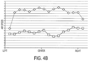
- FIG. 4B is a graph showing air speed measurements taken at locations across the outlets of a fan assembly having partitions, such as the fan assembly of FIG. 3A , in accordance with an exemplary embodiment of the present invention.
- transverse fan assemblies of the present invention are not limited to use in such harvesters, but could equally as well be employed or utilized in or with other harvesters and equipment, including harvesters that employ dual rotor threshing systems and with equipment for other applications, or with other equipment or in other circumstances and situations, consistent with the principles and teachings expounded.
- FIGS. 1 and 2 which are reproduced from U.S. Pat. No. 8,221,064, identify the general location of and depict a conventional transverse fan assembly 10 arranged in operable combination with a typical, conventional, self-propelled agricultural combine harvester 12 of the axial-flow type wherein crop material is threshed and separated while it is advanced by and along a generally longitudinally arranged rotor.
- a threshing apparatus 18 of the combine harvester 12 includes a rotor assembly 20 , including a relatively large diameter rotor 22 that is mounted within a threshing cage 24 . Disposed about the cage 24 is a system of concaves 26 and separating grates 28 which, through the action of the rotor 22 and centrifugal force, act to separate grain material from other crop residue that is too large to pass through the concaves 26 and grates 28 , sometimes hereafter referred to as straw.
- the threshed grain material is delivered to a cleaning system 29 that includes a pair of vertically spaced apart cleaning sieves 30 and 32 while the straw is propelled rearwardly through the rotor assembly 20 where a conventional beater 40 acts upon the crop residue discharged from the rotor assembly 20 .
- Beater 40 propels the crop residue from the rear of the rotor assembly 20 and throws it back for broad discharge from the rear end of the combine.
- an auger 34 moves the threshed grain material to the cleaning sieves 30 and 32 , which sieves form part of the cleaning system 29 and are mounted for oscillation to separate grain from other larger pieces of threshed crop material.
- the sieves 30 and 32 are vibrated or oscillated, the grain falls through the sieves 30 and 32 to an underlying clean grain pan 35 and into a clean grain trough or collector 36 .
- An auger 38 directs the grain from the clean grain trough 36 into a hopper or grain bin (not shown) often housed generally directly behind the cab 12 ( FIG. 1 ) within combine harvester body 14 .
- the threshed grain material that is too large to fall through the sieves 30 and 32 forms a relatively large crop mat or veil extending across substantially the entire sieve construction, as fan assembly 10 provides air that is blown upwardly and rearwardly, as denoted by the arrows, through sieves 30 and 32 .
- Such air flow acts to blow lighter, non-grain elements, sometimes referred to as chaff, away from the crop mat remaining on the sieves 30 and 32 towards the rear of the harvester, where such chaff is handled in conventional and well-known manners.
- one problem with long and wide transverse fans such as the fan assembly 10 of the Prior Art, is that the air blowing through the fan housing will converge towards the center of the fan housing and create a significantly stronger airstream in the center of the fan housing as compared with the sides of the fan housing.
- the air can be unevenly distributed along the width dimension ‘W’ of the fan 10 (the width dimension extends into the sheet of paper in FIG. 2 ).
- FIGS. 3A-3C there is illustrated a transverse fan assembly 300 , in accordance with an exemplary embodiment of the present invention. It is noted that there may be slight structural differences between the fan assemblies 300 shown in FIGS. 3A-3C , and select features of the fan assembly may have been omitted from those figures in order to reveal other features of the exemplary embodiments of the invention described herein.
- the fan assembly 300 is intended to replace the fan assembly 10 of FIGS. 1 and 2 in the combine harvester.
- the fan assembly 300 includes a housing 302 having a series of panels that are mounted together to form an interconnected housing.
- the housing 302 generally includes two side walls 302 a and 302 b defining an exterior width dimension, and a bottom cover 302 c interconnecting the side walls 302 a and 302 b .
- a curved wall 302 d extends to the top side of the fan assembly 300 .
- the curved wall 302 d is connected to the top end of the bottom cover 302 c and is positioned between the side walls 302 a and 302 b .
- the individual walls of the housing 302 including the partitions 320 , which are described in detail below, may be composed of sheet metal, for example.
- the fan assembly 300 includes an air inlet 303 at its top end. Unlike the fan assembly 10 of FIG. 2 , the fan assembly 300 includes two exhaust openings 304 and 306 through which air is exhausted. Air flow 350 through the fan assembly 300 is shown in FIG. 3C .
- the upper opening 304 directs air 354 onto the upper sieve 30 (see FIG. 2 )
- the lower opening 306 directs air 356 onto the lower sieve 32 of the harvester.
- One or more panels 307 connect the side walls 302 a and 302 b to form a top of the lower opening 306 . Behind the panels 307 is disposed a curved divider 308 positioned between the exhaust openings 304 and 306 .
- the curved divider 308 serves to separate the air flow 350 into air flow 354 and air flow 356 .
- the fan assembly 300 includes a single, unitary rotor 310 spanning the entire width W of the fan assembly 300 .
- the rotor 310 includes a series of blades 312 for drawing air through the housing 302 from the inlet 303 to the outlets openings 304 and 306 .
- the rotor 310 may be driven by a single drive.
- a series of partitions 320 a - 320 e are positioned within the housing 302 for segmenting the housing into discrete ducts in order to promote the uniform passage of air across the entire width W of the fan assembly 300 .
- Each partition 320 generally includes a first portion 322 that is disposed over the rotor 310 , a second portion 324 that is at least partially positioned in the upper exhaust opening 304 , and a third portion 326 that is at least partially positioned in the lower exhaust opening 306 .
- Each partition 320 (with the exception of pivoted walls 330 ) is oriented parallel to the side walls 302 a and 302 b and orthogonal to the axis of rotation A of the rotor 310 .
- the first portion 322 extends to an elevation above the rotor 310 and includes a cut-out portion for accommodating the rotor 310 .
- the portions 322 , 324 and 326 may be integral, or connected together by fasteners or welds. Alternatively, the portions 322 , 324 and 326 may be discrete and disconnected.
- the partitions 320 a and 320 e at the ends of the housing 302 may, or may not, include the second and third portions 324 and 326 .
- the first portion 322 of the partitions 320 b and 320 d each include a rotatable wall 330 defined upstream of the fan rotor 310 .
- the wall 330 is hingedly connected to the remainder of the first portion 322 , and is capable of pivoting about a pivot axis to balance the distribution of the air stream across the width W of the housing 302 , as necessary.
- the pivot axis of the wall 330 is oriented orthogonal to the axis ‘A’ of rotation of the rotor 310 .
- FIG. 3A the wall 330 of the partition 320 b is shown pivoted, whereas the wall 330 of the partition 320 d is not shown pivoted.
- the wall 330 may be pivoted by hand, or a separate motor (not shown). It should be understood that any one of the partitions 320 might include the wall 330 . Alternatively, although not shown, the pivotable walls 330 may be replaced by fixed walls (like partition 320 c ).
- the partitions 320 together define separate ducts 340 through which the air flows from the inlet 303 to the outlets 304 and 306 . Separating the air stream into discrete air streams within the ducts 340 promotes even, stable and uniform distribution of the air flow across the entire width W of the fan assembly 300 . In the absence of the separate air flow ducts 340 , the air flow will converge toward the center of the outlets 304 and 306 under heavy or uneven crop load through the combine.
- FIG. 4A is a graph showing air speed measurements taken at locations across the outlets of a conventional fan assembly having upper and lower outlet openings that do not have partitions (i.e., unlike the fan depicted in FIG. 3A ).
- the air speed is non-uniform across the width dimension (shown along the X-axis) of the fan assembly. More particularly, the outlet air speed is comparatively low at the left and right ends of the fan assembly with respect to the center of the fan assembly. In other words, the air is concentrated toward the center of the fan assembly.
- the top line on the graph represents the air speed across an upper opening in the conventional fan assembly, whereas the bottom line on the graph represents the air speed across an lower opening in the conventional fan assembly.
- FIG. 4B is a graph showing air speed measurements taken at locations across the outlets of a fan assembly having partitions, such as the fan assembly 300 .
- the outlet air speed is substantially uniform across the entire width of the fan assembly.
- the air speed is stable (10-14 meters per second) at the center as well as the right and left ends of the fan assembly.
- the top line on the graph represents the air speed across the upper opening 304
- the bottom line on the graph represents the air speed across the lower opening 306 .
Landscapes
- Life Sciences & Earth Sciences (AREA)
- Environmental Sciences (AREA)
- Structures Of Non-Positive Displacement Pumps (AREA)
Priority Applications (3)
| Application Number | Priority Date | Filing Date | Title |
|---|---|---|---|
| US15/726,900 US10561069B2 (en) | 2017-10-06 | 2017-10-06 | Segmented fan housing for cleaning system of combine harvester |
| EP18198423.8A EP3466243B1 (de) | 2017-10-06 | 2018-10-03 | Segmentiertes lüftergehäuse für das reinigungssystem eines mähdreschers |
| BR102018070541-5A BR102018070541B1 (pt) | 2017-10-06 | 2018-10-05 | Conjunto de ventilador para um sistema de limpeza de uma colheitadeira |
Applications Claiming Priority (1)
| Application Number | Priority Date | Filing Date | Title |
|---|---|---|---|
| US15/726,900 US10561069B2 (en) | 2017-10-06 | 2017-10-06 | Segmented fan housing for cleaning system of combine harvester |
Publications (2)
| Publication Number | Publication Date |
|---|---|
| US20190104687A1 US20190104687A1 (en) | 2019-04-11 |
| US10561069B2 true US10561069B2 (en) | 2020-02-18 |
Family
ID=63762267
Family Applications (1)
| Application Number | Title | Priority Date | Filing Date |
|---|---|---|---|
| US15/726,900 Active 2038-02-04 US10561069B2 (en) | 2017-10-06 | 2017-10-06 | Segmented fan housing for cleaning system of combine harvester |
Country Status (2)
| Country | Link |
|---|---|
| US (1) | US10561069B2 (de) |
| EP (1) | EP3466243B1 (de) |
Cited By (4)
| Publication number | Priority date | Publication date | Assignee | Title |
|---|---|---|---|---|
| US20200060093A1 (en) * | 2018-08-23 | 2020-02-27 | Tribine Industries Llc | Air Chute Feed Assembly for A Crossflow Cleaning Fan Assembly |
| RU201950U1 (ru) * | 2020-08-11 | 2021-01-21 | Открытое акционерное общество "Гомсельмаш" | Центробежный вентилятор системы очистки зерноуборочного комбайна |
| US11058055B2 (en) * | 2016-07-06 | 2021-07-13 | Tribine Industries, LLC | Airflow for an agricultural harvesting combine |
| WO2022040503A1 (en) | 2020-08-20 | 2022-02-24 | Cnh Industrial America Llc | Deflector for fan housing of cleaning system of combine harvester |
Families Citing this family (2)
| Publication number | Priority date | Publication date | Assignee | Title |
|---|---|---|---|---|
| EP3566568B1 (de) * | 2018-05-09 | 2022-08-10 | CNH Industrial Belgium N.V. | Luftleitblech für eine mähdrescherreinigungsanordnung |
| US11944040B2 (en) | 2021-02-02 | 2024-04-02 | Cnh Industrial America Llc | Closed loop combine cleaning fan control |
Citations (27)
| Publication number | Priority date | Publication date | Assignee | Title |
|---|---|---|---|---|
| DE289559C (de) | ||||
| US2682951A (en) * | 1952-11-24 | 1954-07-06 | Hamburg Samuel | Fan for combine separators |
| US2849118A (en) * | 1956-02-20 | 1958-08-26 | Massey Ferguson Inc | Fanning mill for combines |
| DE1077368B (de) | 1957-11-21 | 1960-03-10 | Westerasmaskiner Ab | Zentrifugalgeblaese von relativ zum Laufraddurchmesser grosser Breite |
| US2954123A (en) * | 1957-09-12 | 1960-09-27 | Massey Ferguson Australia Ltd | Harvesting machine or combine |
| GB860716A (en) | 1956-09-17 | 1961-02-08 | Massey Ferguson Australia Ltd | Improvements relating to harvesting machines |
| US3049128A (en) * | 1959-06-05 | 1962-08-14 | Massey Ferguson Inc | Straw walkers having inclined plates |
| BE743106A (de) | 1969-12-15 | 1970-05-14 | ||
| GB2051954A (en) | 1979-06-02 | 1981-01-21 | Claas Ohg | Fan for the cleaning apparatus of combine harvesters |
| US4265077A (en) * | 1979-08-03 | 1981-05-05 | Deere & Company | Blower system for an axial flow rotary combine cleaning shoe |
| US4397319A (en) * | 1981-03-31 | 1983-08-09 | Deere & Company | Cleaning device for harvesting machines |
| US5165855A (en) * | 1991-06-25 | 1992-11-24 | Case Corporation | Transverse blower fan and method of assembly |
| US5599162A (en) * | 1995-08-09 | 1997-02-04 | Case Corporation | Transverse blower fan assembly |
| US6558252B2 (en) * | 2000-08-01 | 2003-05-06 | Claas Selbstfahrende Erntemaschinen Gmbh | Blower for combine harvesters having a separation unit |
| JP2004278473A (ja) | 2003-03-18 | 2004-10-07 | Matsushita Electric Ind Co Ltd | 送風装置 |
| US20050013685A1 (en) * | 2003-07-18 | 2005-01-20 | Ricketts Jonathan E. | Cross flow fan |
| US20080004091A1 (en) * | 2006-06-29 | 2008-01-03 | Ricketts Jon E | Chevron inlet for cross flow fan |
| US20080004090A1 (en) * | 2006-06-30 | 2008-01-03 | Ricketts Jon E | Rotating inlet for cross flow fan |
| US20080146299A1 (en) * | 2006-12-13 | 2008-06-19 | Matousek Robert A | Integrated axle and cleaning fan wrapper for an agricultural harvesting machine |
| US7416482B2 (en) * | 2005-06-16 | 2008-08-26 | Deere & Company | Combine harvester blower having convex wind channel side walls |
| WO2008149233A2 (en) | 2007-06-08 | 2008-12-11 | Agco Do Brasil Comercio E Indústria Ltda. | Fan for combines |
| US20090163260A1 (en) | 2007-12-20 | 2009-06-25 | Ulrich Claes | Combine harvester having blower for pneumatic cleaning |
| US8221064B2 (en) | 2008-11-18 | 2012-07-17 | Cnh America Llc | Transverse fan assembly having a supplementary air feed inlet for infill of air flow deficiencies to effect a desired output air flow pattern, and method of use thereof |
| US20120184339A1 (en) * | 2011-01-14 | 2012-07-19 | Waldemar Schulz | Combine harvester |
| US9033779B2 (en) * | 2012-11-29 | 2015-05-19 | Cnh Industrial America Llc | Air diverter for a cleaning system of a combine harvester |
| US9119350B2 (en) * | 2012-12-06 | 2015-09-01 | Cnh Industrial America Llc | Grain cleaning method for an agricultural combine |
| US20180007830A1 (en) * | 2016-07-06 | 2018-01-11 | Tribine Industries Llc | Airflow for an Agricultural Harvesting Combine |
-
2017
- 2017-10-06 US US15/726,900 patent/US10561069B2/en active Active
-
2018
- 2018-10-03 EP EP18198423.8A patent/EP3466243B1/de active Active
Patent Citations (29)
| Publication number | Priority date | Publication date | Assignee | Title |
|---|---|---|---|---|
| DE289559C (de) | ||||
| US2682951A (en) * | 1952-11-24 | 1954-07-06 | Hamburg Samuel | Fan for combine separators |
| US2849118A (en) * | 1956-02-20 | 1958-08-26 | Massey Ferguson Inc | Fanning mill for combines |
| GB860716A (en) | 1956-09-17 | 1961-02-08 | Massey Ferguson Australia Ltd | Improvements relating to harvesting machines |
| US2954123A (en) * | 1957-09-12 | 1960-09-27 | Massey Ferguson Australia Ltd | Harvesting machine or combine |
| DE1077368B (de) | 1957-11-21 | 1960-03-10 | Westerasmaskiner Ab | Zentrifugalgeblaese von relativ zum Laufraddurchmesser grosser Breite |
| US3049128A (en) * | 1959-06-05 | 1962-08-14 | Massey Ferguson Inc | Straw walkers having inclined plates |
| BE743106A (de) | 1969-12-15 | 1970-05-14 | ||
| GB2051954A (en) | 1979-06-02 | 1981-01-21 | Claas Ohg | Fan for the cleaning apparatus of combine harvesters |
| US4303079A (en) | 1979-06-02 | 1981-12-01 | Claas Ohg | Radial blowing device for a cleaning arrangement of a harvester thresher |
| US4265077A (en) * | 1979-08-03 | 1981-05-05 | Deere & Company | Blower system for an axial flow rotary combine cleaning shoe |
| US4397319A (en) * | 1981-03-31 | 1983-08-09 | Deere & Company | Cleaning device for harvesting machines |
| US5165855A (en) * | 1991-06-25 | 1992-11-24 | Case Corporation | Transverse blower fan and method of assembly |
| US5599162A (en) * | 1995-08-09 | 1997-02-04 | Case Corporation | Transverse blower fan assembly |
| US6558252B2 (en) * | 2000-08-01 | 2003-05-06 | Claas Selbstfahrende Erntemaschinen Gmbh | Blower for combine harvesters having a separation unit |
| JP2004278473A (ja) | 2003-03-18 | 2004-10-07 | Matsushita Electric Ind Co Ltd | 送風装置 |
| US20050013685A1 (en) * | 2003-07-18 | 2005-01-20 | Ricketts Jonathan E. | Cross flow fan |
| US7416482B2 (en) * | 2005-06-16 | 2008-08-26 | Deere & Company | Combine harvester blower having convex wind channel side walls |
| US20080004091A1 (en) * | 2006-06-29 | 2008-01-03 | Ricketts Jon E | Chevron inlet for cross flow fan |
| US20080004090A1 (en) * | 2006-06-30 | 2008-01-03 | Ricketts Jon E | Rotating inlet for cross flow fan |
| US20080146299A1 (en) * | 2006-12-13 | 2008-06-19 | Matousek Robert A | Integrated axle and cleaning fan wrapper for an agricultural harvesting machine |
| WO2008149233A2 (en) | 2007-06-08 | 2008-12-11 | Agco Do Brasil Comercio E Indústria Ltda. | Fan for combines |
| US20090163260A1 (en) | 2007-12-20 | 2009-06-25 | Ulrich Claes | Combine harvester having blower for pneumatic cleaning |
| US8221064B2 (en) | 2008-11-18 | 2012-07-17 | Cnh America Llc | Transverse fan assembly having a supplementary air feed inlet for infill of air flow deficiencies to effect a desired output air flow pattern, and method of use thereof |
| US20120184339A1 (en) * | 2011-01-14 | 2012-07-19 | Waldemar Schulz | Combine harvester |
| US9125346B2 (en) | 2011-01-14 | 2015-09-08 | Claas Selbstfahrende Erntemaschinen Gmbh | Combine harvester |
| US9033779B2 (en) * | 2012-11-29 | 2015-05-19 | Cnh Industrial America Llc | Air diverter for a cleaning system of a combine harvester |
| US9119350B2 (en) * | 2012-12-06 | 2015-09-01 | Cnh Industrial America Llc | Grain cleaning method for an agricultural combine |
| US20180007830A1 (en) * | 2016-07-06 | 2018-01-11 | Tribine Industries Llc | Airflow for an Agricultural Harvesting Combine |
Non-Patent Citations (1)
| Title |
|---|
| Extended European Search Report for EP Application No. 18198423.8 dated Mar. 11, 2019 (6 pages). |
Cited By (5)
| Publication number | Priority date | Publication date | Assignee | Title |
|---|---|---|---|---|
| US11058055B2 (en) * | 2016-07-06 | 2021-07-13 | Tribine Industries, LLC | Airflow for an agricultural harvesting combine |
| US20200060093A1 (en) * | 2018-08-23 | 2020-02-27 | Tribine Industries Llc | Air Chute Feed Assembly for A Crossflow Cleaning Fan Assembly |
| US10849276B2 (en) * | 2018-08-23 | 2020-12-01 | Tribine Industries, LLC | Air chute feed assembly for a crossflow cleaning fan assembly |
| RU201950U1 (ru) * | 2020-08-11 | 2021-01-21 | Открытое акционерное общество "Гомсельмаш" | Центробежный вентилятор системы очистки зерноуборочного комбайна |
| WO2022040503A1 (en) | 2020-08-20 | 2022-02-24 | Cnh Industrial America Llc | Deflector for fan housing of cleaning system of combine harvester |
Also Published As
| Publication number | Publication date |
|---|---|
| EP3466243A1 (de) | 2019-04-10 |
| EP3466243B1 (de) | 2023-12-06 |
| BR102018070541A2 (pt) | 2019-04-24 |
| US20190104687A1 (en) | 2019-04-11 |
Similar Documents
| Publication | Publication Date | Title |
|---|---|---|
| US10561069B2 (en) | Segmented fan housing for cleaning system of combine harvester | |
| US8221064B2 (en) | Transverse fan assembly having a supplementary air feed inlet for infill of air flow deficiencies to effect a desired output air flow pattern, and method of use thereof | |
| US6921330B2 (en) | Front chaffer and cleaning fan | |
| US8062109B1 (en) | Dust suppressor for combine harvester feederhouse | |
| US9686916B2 (en) | Cleaning shoe MOG discharge system | |
| US8608534B1 (en) | Rolled secondary cut off in air distribution system of a combine harvester | |
| US9717183B2 (en) | Grain cleaning unit with cleaning airstream vented above grain pan for a combine harvester | |
| PL125114B1 (en) | Combine harvester | |
| US6669558B1 (en) | Tailings conveyor housing | |
| US9736985B2 (en) | Agricultural harvester auger assembly | |
| WO2008149233A2 (en) | Fan for combines | |
| US7025673B2 (en) | Tailings conveyor system | |
| US20090163260A1 (en) | Combine harvester having blower for pneumatic cleaning | |
| WO2013101971A1 (en) | Multiple fan blade angles in a single crossflow fan | |
| US20230389479A1 (en) | Deflector for fan housing of cleaning system of combine harvester | |
| CN107846844B (zh) | 农业收割机的螺旋输送器组件 | |
| US20120315964A1 (en) | Air diverter for combine shoe | |
| EP3566568B1 (de) | Luftleitblech für eine mähdrescherreinigungsanordnung | |
| JP3540932B2 (ja) | 脱穀機 | |
| US20230210055A1 (en) | Variable cross-section vane for transition cone in combine harvester | |
| GB2452240A (en) | Combine harvester fan | |
| BR102018070541B1 (pt) | Conjunto de ventilador para um sistema de limpeza de uma colheitadeira | |
| US20140357332A1 (en) | Geometry for controlling air velocity in a combine harvester | |
| JPH11266675A (ja) | 脱穀機 |
Legal Events
| Date | Code | Title | Description |
|---|---|---|---|
| FEPP | Fee payment procedure |
Free format text: ENTITY STATUS SET TO UNDISCOUNTED (ORIGINAL EVENT CODE: BIG.); ENTITY STATUS OF PATENT OWNER: LARGE ENTITY |
|
| AS | Assignment |
Owner name: CNH INDUSTRIAL AMERICA LLC, PENNSYLVANIA Free format text: ASSIGNMENT OF ASSIGNORS INTEREST;ASSIGNORS:THOMAS, JEFFREY D.;LINDE, KARL;REEL/FRAME:043860/0367 Effective date: 20171006 |
|
| STPP | Information on status: patent application and granting procedure in general |
Free format text: DOCKETED NEW CASE - READY FOR EXAMINATION |
|
| STPP | Information on status: patent application and granting procedure in general |
Free format text: NON FINAL ACTION MAILED |
|
| STPP | Information on status: patent application and granting procedure in general |
Free format text: RESPONSE TO NON-FINAL OFFICE ACTION ENTERED AND FORWARDED TO EXAMINER |
|
| STPP | Information on status: patent application and granting procedure in general |
Free format text: NOTICE OF ALLOWANCE MAILED -- APPLICATION RECEIVED IN OFFICE OF PUBLICATIONS |
|
| STCF | Information on status: patent grant |
Free format text: PATENTED CASE |
|
| AS | Assignment |
Owner name: BLUE LEAF I.P., INC., DELAWARE Free format text: ASSIGNMENT OF ASSIGNORS INTEREST;ASSIGNOR:CNH INDUSTRIAL AMERICA LLC;REEL/FRAME:052741/0936 Effective date: 20200508 |
|
| MAFP | Maintenance fee payment |
Free format text: PAYMENT OF MAINTENANCE FEE, 4TH YEAR, LARGE ENTITY (ORIGINAL EVENT CODE: M1551); ENTITY STATUS OF PATENT OWNER: LARGE ENTITY Year of fee payment: 4 |