US10551301B2 - Brightness colorimeter having measurement error caused by linearly polarized light, which is corrected - Google Patents
Brightness colorimeter having measurement error caused by linearly polarized light, which is corrected Download PDFInfo
- Publication number
- US10551301B2 US10551301B2 US15/588,943 US201715588943A US10551301B2 US 10551301 B2 US10551301 B2 US 10551301B2 US 201715588943 A US201715588943 A US 201715588943A US 10551301 B2 US10551301 B2 US 10551301B2
- Authority
- US
- United States
- Prior art keywords
- light
- directions
- module
- spectral
- brightness
- Prior art date
- Legal status (The legal status is an assumption and is not a legal conclusion. Google has not performed a legal analysis and makes no representation as to the accuracy of the status listed.)
- Active, expires
Links
- 238000005259 measurement Methods 0.000 title claims abstract description 41
- 230000003595 spectral effect Effects 0.000 claims abstract description 68
- 230000010287 polarization Effects 0.000 claims abstract description 38
- 238000006243 chemical reaction Methods 0.000 claims abstract description 31
- 238000001228 spectrum Methods 0.000 claims abstract description 19
- 230000003287 optical effect Effects 0.000 claims description 6
- 230000000007 visual effect Effects 0.000 claims description 2
- 230000007547 defect Effects 0.000 description 4
- 238000005516 engineering process Methods 0.000 description 4
- 230000004075 alteration Effects 0.000 description 3
- 230000000694 effects Effects 0.000 description 3
- 206010010071 Coma Diseases 0.000 description 1
- 239000010408 film Substances 0.000 description 1
- 238000003384 imaging method Methods 0.000 description 1
- 239000004973 liquid crystal related substance Substances 0.000 description 1
- 238000000034 method Methods 0.000 description 1
- 238000004611 spectroscopical analysis Methods 0.000 description 1
- 239000010409 thin film Substances 0.000 description 1
- 238000002834 transmittance Methods 0.000 description 1
Images


Classifications
-
- G—PHYSICS
- G01—MEASURING; TESTING
- G01J—MEASUREMENT OF INTENSITY, VELOCITY, SPECTRAL CONTENT, POLARISATION, PHASE OR PULSE CHARACTERISTICS OF INFRARED, VISIBLE OR ULTRAVIOLET LIGHT; COLORIMETRY; RADIATION PYROMETRY
- G01J5/00—Radiation pyrometry, e.g. infrared or optical thermometry
- G01J5/60—Radiation pyrometry, e.g. infrared or optical thermometry using determination of colour temperature
- G01J5/602—Radiation pyrometry, e.g. infrared or optical thermometry using determination of colour temperature using selective, monochromatic or bandpass filtering
-
- G—PHYSICS
- G01—MEASURING; TESTING
- G01N—INVESTIGATING OR ANALYSING MATERIALS BY DETERMINING THEIR CHEMICAL OR PHYSICAL PROPERTIES
- G01N21/00—Investigating or analysing materials by the use of optical means, i.e. using sub-millimetre waves, infrared, visible or ultraviolet light
- G01N21/17—Systems in which incident light is modified in accordance with the properties of the material investigated
- G01N21/25—Colour; Spectral properties, i.e. comparison of effect of material on the light at two or more different wavelengths or wavelength bands
- G01N21/251—Colorimeters; Construction thereof
-
- G—PHYSICS
- G01—MEASURING; TESTING
- G01J—MEASUREMENT OF INTENSITY, VELOCITY, SPECTRAL CONTENT, POLARISATION, PHASE OR PULSE CHARACTERISTICS OF INFRARED, VISIBLE OR ULTRAVIOLET LIGHT; COLORIMETRY; RADIATION PYROMETRY
- G01J3/00—Spectrometry; Spectrophotometry; Monochromators; Measuring colours
- G01J3/02—Details
- G01J3/0205—Optical elements not provided otherwise, e.g. optical manifolds, diffusers, windows
- G01J3/0224—Optical elements not provided otherwise, e.g. optical manifolds, diffusers, windows using polarising or depolarising elements
-
- G—PHYSICS
- G01—MEASURING; TESTING
- G01J—MEASUREMENT OF INTENSITY, VELOCITY, SPECTRAL CONTENT, POLARISATION, PHASE OR PULSE CHARACTERISTICS OF INFRARED, VISIBLE OR ULTRAVIOLET LIGHT; COLORIMETRY; RADIATION PYROMETRY
- G01J3/00—Spectrometry; Spectrophotometry; Monochromators; Measuring colours
- G01J3/02—Details
- G01J3/0205—Optical elements not provided otherwise, e.g. optical manifolds, diffusers, windows
- G01J3/0208—Optical elements not provided otherwise, e.g. optical manifolds, diffusers, windows using focussing or collimating elements, e.g. lenses or mirrors; performing aberration correction
-
- G—PHYSICS
- G01—MEASURING; TESTING
- G01J—MEASUREMENT OF INTENSITY, VELOCITY, SPECTRAL CONTENT, POLARISATION, PHASE OR PULSE CHARACTERISTICS OF INFRARED, VISIBLE OR ULTRAVIOLET LIGHT; COLORIMETRY; RADIATION PYROMETRY
- G01J3/00—Spectrometry; Spectrophotometry; Monochromators; Measuring colours
- G01J3/46—Measurement of colour; Colour measuring devices, e.g. colorimeters
- G01J3/465—Measurement of colour; Colour measuring devices, e.g. colorimeters taking into account the colour perception of the eye; using tristimulus detection
-
- G—PHYSICS
- G01—MEASURING; TESTING
- G01J—MEASUREMENT OF INTENSITY, VELOCITY, SPECTRAL CONTENT, POLARISATION, PHASE OR PULSE CHARACTERISTICS OF INFRARED, VISIBLE OR ULTRAVIOLET LIGHT; COLORIMETRY; RADIATION PYROMETRY
- G01J3/00—Spectrometry; Spectrophotometry; Monochromators; Measuring colours
- G01J3/46—Measurement of colour; Colour measuring devices, e.g. colorimeters
- G01J3/50—Measurement of colour; Colour measuring devices, e.g. colorimeters using electric radiation detectors
- G01J3/502—Measurement of colour; Colour measuring devices, e.g. colorimeters using electric radiation detectors using a dispersive element, e.g. grating, prism
-
- G—PHYSICS
- G01—MEASURING; TESTING
- G01J—MEASUREMENT OF INTENSITY, VELOCITY, SPECTRAL CONTENT, POLARISATION, PHASE OR PULSE CHARACTERISTICS OF INFRARED, VISIBLE OR ULTRAVIOLET LIGHT; COLORIMETRY; RADIATION PYROMETRY
- G01J3/00—Spectrometry; Spectrophotometry; Monochromators; Measuring colours
- G01J3/46—Measurement of colour; Colour measuring devices, e.g. colorimeters
- G01J3/50—Measurement of colour; Colour measuring devices, e.g. colorimeters using electric radiation detectors
- G01J3/506—Measurement of colour; Colour measuring devices, e.g. colorimeters using electric radiation detectors measuring the colour produced by screens, monitors, displays or CRTs
-
- G—PHYSICS
- G01—MEASURING; TESTING
- G01J—MEASUREMENT OF INTENSITY, VELOCITY, SPECTRAL CONTENT, POLARISATION, PHASE OR PULSE CHARACTERISTICS OF INFRARED, VISIBLE OR ULTRAVIOLET LIGHT; COLORIMETRY; RADIATION PYROMETRY
- G01J3/00—Spectrometry; Spectrophotometry; Monochromators; Measuring colours
- G01J3/46—Measurement of colour; Colour measuring devices, e.g. colorimeters
- G01J3/50—Measurement of colour; Colour measuring devices, e.g. colorimeters using electric radiation detectors
- G01J3/51—Measurement of colour; Colour measuring devices, e.g. colorimeters using electric radiation detectors using colour filters
- G01J3/513—Measurement of colour; Colour measuring devices, e.g. colorimeters using electric radiation detectors using colour filters having fixed filter-detector pairs
-
- G—PHYSICS
- G01—MEASURING; TESTING
- G01J—MEASUREMENT OF INTENSITY, VELOCITY, SPECTRAL CONTENT, POLARISATION, PHASE OR PULSE CHARACTERISTICS OF INFRARED, VISIBLE OR ULTRAVIOLET LIGHT; COLORIMETRY; RADIATION PYROMETRY
- G01J4/00—Measuring polarisation of light
-
- G—PHYSICS
- G01—MEASURING; TESTING
- G01J—MEASUREMENT OF INTENSITY, VELOCITY, SPECTRAL CONTENT, POLARISATION, PHASE OR PULSE CHARACTERISTICS OF INFRARED, VISIBLE OR ULTRAVIOLET LIGHT; COLORIMETRY; RADIATION PYROMETRY
- G01J4/00—Measuring polarisation of light
- G01J4/04—Polarimeters using electric detection means
-
- G—PHYSICS
- G01—MEASURING; TESTING
- G01N—INVESTIGATING OR ANALYSING MATERIALS BY DETERMINING THEIR CHEMICAL OR PHYSICAL PROPERTIES
- G01N21/00—Investigating or analysing materials by the use of optical means, i.e. using sub-millimetre waves, infrared, visible or ultraviolet light
- G01N21/17—Systems in which incident light is modified in accordance with the properties of the material investigated
- G01N21/25—Colour; Spectral properties, i.e. comparison of effect of material on the light at two or more different wavelengths or wavelength bands
- G01N21/255—Details, e.g. use of specially adapted sources, lighting or optical systems
Definitions
- the present disclosure relates to a brightness colorimeter having a measurement error caused by linearly polarized light, which is corrected, and more particularly, to a brightness colorimeter which is configured to convert linearly polarized light for incident light into circularly polarized light and then measure brightness and chromaticity and has a measurement error that may occur due to incidence of the linearly polarized light.
- a general display device has a structure that intersects light emitted from a back light through a polarizer film, to change brightness of pixels by electrically adjusting a parallel direction of liquid crystals for each pixel.
- the linearly-polarized light may be frequently included in light irradiated through the display device, and such linearly polarized light is a cause of errors in measuring the chromaticity and the brightness.
- the linearly polarized light is a cause that when the chromaticity and the brightness are measured through a light source irradiated from the display device, a measurement value largely differs as arrangement of the display device is changed to a lateral direction or a longitudinal direction, and the linearly polarized light thus makes accurate measurement of the chromaticity and the brightness difficult.
- the present disclosure is conceived to solve the above problems according to the related art, and an aspect of the present disclosure is to provide a brightness colorimeter that may overcome errors in resultant values obtained by measuring the chromaticity and the brightness according to polarization characteristics of light input from an object to be measured and thus, more accurately measure the chromaticity and the brightness.
- a brightness colorimeter having a measurement error caused by linearly polarized light which is corrected, according to the present disclosure, may include: a lens module to which light irradiated from one side is input; a polarization conversion module configured to intersect the light input through the lens module to convert polarization characteristics; a spectral module provided in one unit block to reflect and intersect the light input through the polarization conversion module so as to branch the light in different three directions; filter modules arranged on progress paths of the light branched in different three direction through the spectral module to intersect monochromatic light beams having specific spectra among the light branched in the three directions; and measurement modules arranged to correspond to exit angles of the monochromatic light beams passed through the filter modules, to measure at least one of a brightness, a chromaticity, and an error obtained by the monochromatic light beams.
- a brightness colorimeter having a measurement error caused by linearly polarized light which is corrected, according to the present disclosure, may include: a lens module to which light irradiated from one side is input; a spectral module provided in one unit block to reflect and intersect the light input through the polarization conversion module so as to branch the light in different three directions; polarization conversion modules provided on progress paths of the light branched in different three directions through the spectral module, to intersect the light branched in the different three directions; filter modules arranged on the progress paths of the light branched in different three directions via the polarization conversion modules, to convert the received light into monochromatic light beams having specific spectra; and measurement modules arranged to correspond to exit angles of the monochromatic light beams passed through the filter modules, to measure at least one of a brightness, a chromaticity, and an error obtained by the monochromatic light beams.
- the polarization conversion module may include a wavelength plate configured to convert the linearly polarized light into the circularly polarized light.
- the wavelength plate may be a quarter wave plate having a predetermined thickness such that the linearly polarized light vibrating in directions that are vertical to each other generates an optical path difference of a wavelength of ⁇ /4.
- the spectral module may include: a first spectral body configured to branch input light in different two directions by reflecting and intersecting the input light; and a second spectral body configured to branch the light passed through the first spectral body in different two directions by reflecting and intersecting the light, wherein distances from a point at which the light is input to the first spectral body via different three directions to the filter modules are identical to each other.
- the total amount of the light input to the first spectral body is 1, the total amount of the light branched in different three directions may be a third.
- images obtained by the monochromatic light beams passed through the filter modules may have measurement errors caused by the linearly polarized light having the same visual range.
- the filter modules may convert the light branched in the three different directions into a spectrum corresponding to an X value, a spectrum corresponding to a Y value and a spectrum corresponding to a Z value among tri-stimulus.
- a brightness colorimeter having a measurement error caused by linearly polarized light which is corrected, according to the present disclosure for solving the above problems, may measure the chromaticity and the brightness by converting linearly polarized light into circularly polarized light, and may thus identically deduce the chromaticity and the brightness having high reliability regardless of an arrangement direction of an object to be measured.
- the brightness colorimeter is configured such that linearly polarized light that may be generated through a spectral body such as a prism provided in a spectral module is also converted into circularly polarized light and the converted light arrives at a measurement module, so that measurement reliability for the chromaticity and the brightness may be improved.
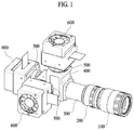
- FIG. 1 is a perspective view illustrating a brightness colorimeter having a measurement error caused by linearly polarized light, which is corrected, according to an embodiment of the present disclosure
- FIG. 2 is an exploded perspective view illustrating a brightness colorimeter having a measurement error caused by linearly polarized light, which is corrected, according to the embodiment of the present disclosure
- FIG. 3 is a sectional view illustrating a brightness colorimeter having a measurement error caused by linearly polarized light, which is corrected, according to the embodiment of the present disclosure
- FIG. 4 is a schematic view illustrating a brightness colorimeter having a measurement error caused by linearly polarized light, which is corrected, according to the embodiment of the present disclosure
- FIG. 5 is a table representing data obtained by measuring tri-stimulus values while arrangement of a subject to be measured is changed through the related art
- FIG. 6 is a table representing data obtained by measuring tri-stimulus values while arrangement of a subject to be measured is changed, through a brightness colorimeter having a measurement error caused by linearly polarized light, which is corrected, according to the embodiment of the present disclosure.
- FIG. 7 is a schematic view illustrating characteristics of a quarter wavelength plate, which is included in a brightness colorimeter having a measurement error caused by linearly polarized light, which is corrected, according to the embodiment of the present disclosure.
- a brightness colorimeter having a measurement error caused by linearly polarized light, which is corrected, according to the present disclosure, will be implemented below.
- FIG. 1 is a perspective view illustrating a brightness colorimeter having a measurement error caused by linearly polarized light, which is corrected, according to an embodiment of the present disclosure
- FIG. 2 is an exploded perspective view illustrating a brightness colorimeter having a measurement error caused by linearly polarized light, which is corrected, according to the embodiment of the present disclosure
- FIG. 3 is a sectional view illustrating a brightness colorimeter having a measurement error caused by linearly polarized light, which is corrected, according to the embodiment of the present disclosure.
- a brightness colorimeter having a measurement error caused by linearly polarized light which is corrected, according to an embodiment of the present disclosure, mainly includes a lens module 100 to which light irradiated from one side is input, a polarization conversion module 200 through which light input through the lens module 100 passes to convert polarization characteristics, a spectral module 400 provided in one unit block to reflect and intersect light input through the polarization conversion module 200 to branch the light into different three paths, filter modules 500 arranged on progress paths of the light branched into the different three paths to intersect monochromatic light beams having specific spectra among the light branched into three directions, and measurement modules 600 arranged to correspond to exit angles of the monochromatic light beams passed through the filter modules 500 to measure at least one of the brightness, the chromaticity and the defect of each of the monochromatic light beams.
- the brightness colorimeter includes a lens module 100 to which light irradiated from one side is input, a spectral module 400 provided in one unit block to reflect and intersect light input through the lens module 100 so as to branch the light into different three directions, a polarization conversion module 200 arranged on progress paths of the light branched into different three paths through the spectral module 400 to intersect the light branched into the different three directions so as to convert polarization characteristics of the light, filter modules 500 arranged on progress paths of the light branched into the different three directions through the polarization conversion module 200 to convert the received light into monochromatic light beams having specific spectra, and measurement modules 600 arranged to correspond to exit angles of the monochromatic light beams passed through the filter modules 500 to measure at least one of the brightness, the chromaticity and the defect of each of the monochromatic light beams.
- a lens module 100 may include a plurality of lens including an object lens (objective lens), an attachment lens and the like.
- the lens module 100 including the plurality of lens may be a combination formed by sequentially arranging a plurality of lens on a path of incident light.
- the lens module 100 may collect light emitted from a display device that is a subject S to be measured, to project the light onto the spectral module 400 or the polarization conversion module 200 , and a plurality of lens 120 are fastened to an inner circumference of the first housing 110 to be coupled to each other, so that spherical aberration, coma aberration and color aberration may be sufficiently corrected.
- Such an object lens used in the lens module 100 may be a Fraunhofer type lens, a Gauss type lens and a Taylor type lens.
- object module 100 may be implemented in various shapes and combinations according to embodiments to which the present disclosure is applied.
- the brightness colorimeter may further include a telecentric module configured to collect light passed through the lens module 100 to improve straightness of light and a light concentrating property.
- the telecentric module may be arranged between the lens module 100 and the spectral module 400 or between the lens module 100 and the polarization conversion module 200 , and the telecentric module may be arranged on a progress path of light that is passed through the lens module 100 and is input to the spectral module 400 or the polarization conversion module 200 .
- the polarization conversion module 200 may include a wavelength plate 220 restrained at an inside of the second housing 210 .
- the wavelength plate 220 may be implemented in a quarter wavelength plate that is a birefringent plate having a predetermined thickness such that an optical path difference corresponding to a wavelength of ⁇ /4 is generated between linearly-polarized light vibrating in directions that are perpendicular to each other.
- the linearly polarized light input from one side of the wavelength plate 220 along a normal line thereof is converted into circularly polarized light and the circularly polarized light is projected into the other side of the wavelength plate 220 along the normal line thereof.
- the linearly polarized light and the circularly polarized light are kinds of polarization.
- the linearly polarized light is light having a vibration direction of a light wave, which is direction 1 and thus having vibrations included in a plane 1 when progress of light is considered, and the circularly polarized light has a vibration direction of a light wave, which corresponds to circular vibration.
- the quarter wavelength plate is configured to convert circularly polarized light into linearly polarized light or linearly polarized light into circularly polarized light to intersect the converted light, and in an embodiment of the present disclosure, is configured to convert linearly polarized light of light input via the lens module 100 from a display device that is a subject S to be measured into circularly polarized light via the polarization conversion module 200 .
- such a polarization conversion module 200 may be arranged to be adjacent to the lens module 100 and may be configured to convert the linearly polarized light of the light input via the lens module 100 into the circularly polarized light, intersect the converted light, and transfer the passed light to the spectral module 400 .
- the polarization conversion modules 200 may be arranged to be adjacent to the filter modules 500 on the paths of the light branched into the different three directions through the spectral module 400 , which will be described below.
- the three polarization conversion modules 200 are provided on the different paths to convert even linearly converted light that may be generated through an optical component such as a prism provided in the spectral module 400 as well as the linearly polarized light of the light input from the display device that is the subject S to be measured and intersect the converted light, more excellent measurement performance may be obtained as compared with the first embodiment.
- the spectral module 400 is provided in one unit block and may be coupled to the lens module 100 or the polarization conversion module 200 through a barrel 300 serving as an optical path for compensating for a path of light input through the lens module 100 or the polarization conversion module 200 .
- the spectral module 400 may branch the light passed through the barrel 300 into different three directions by reflecting some of the light and intersecting some of the light.
- FIG. 4 is a schematic view illustrating a brightness colorimeter having a measurement error caused by linearly polarized light, which is corrected, according to the embodiment of the present disclosure.
- the spectral module 400 may be provided in one unit block including a first spectral body 422 that reflects some of the light passed through the barrel 300 and intersect the other of the light and a second spectral body 424 that reflects some of the light passed through the first spectral body 422 and intersects the other of the light.
- the first spectral body 422 and the second spectral body 424 corresponding to the spectral body 420 provided in one unit block at a predetermined angle are provided, so that the light progressed along a path of the light passed through the barrel 300 may be branched into different three directions.
- directions of the branched light may be changed depending on set angles of the first spectral body 422 and the second spectral body 424 .
- spectral transmittances of the first spectral body 422 and the second spectral body 424 may be constantly configured in a range of 0 degree to 45 degrees.
- incident surfaces of the first spectral body 422 and the second spectral body 424 at which the light input via the barrel 300 arrives and exit surfaces from which the light branched into three directions is output are provided such that incident angles and exit angles of the passed light are perpendicular to each other.
- such a spectral module 400 may branch the light into three directions and output the branched light through the exit surfaces such that an amount of each light is a third of the total amount of the light.
- an incident angle of the light that is input to the spectral module 300 through the lens module 100 or the polarization conversion module 200 by the above-described telecentric module is maintained to be perpendicular to an incident surface of the spectral body 420 and straightness of light and a light concentrating property may be ensured.
- incident angles of the light branched in different three directions and input to the filter modules 500 via the spectral module 400 by the telecentric module may be maintained at specific angles, and the light is input while being collected.
- the spectral module 400 may be formed such that progress distances by which the light branched in different three directions is input to one unit block and is then output therefrom are identical to each other.
- a progress distance of light reflected through the first spectral body 422 , a progress distance of light passing through the first spectral body 422 and reflected through the second spectral body 424 and a progress distance of light passing through the first spectral body 422 and the second spectral body 424 may be equal to each other.
- an angle of the light output from the spectral module and input to an indirect filter module through the telecentric module may be maintained constant and the light may be input to the filter modules 500 while being collected as well.
- the filter modules 500 may be arranged to be adjacent to the spectral module 400 or the polarization conversion module 200 , which will be described, and may include three filters 520 arranged on the progress paths of the light branched in different three directions via the spectral module 400 or the polarization conversion module 200 .
- Such filters 520 which may be coupled to insides of fourth housings 510 and filter only the monochromatic light beams having specific spectra using an interference phenomenon occurring on a thin film, may intersect only the monochromatic light beams having specific spectra among the light branched through the spectral module 400 .
- the monochromatic light beams filtered by the filters 520 may be included in specific spectra of X, Y and Z regions depending on tri-stimulus values according to the standard colorimetric system (CIE 1931) defined by Commission Internationale de l'Eclairage (CIE).
- the filter modules 500 may include a filter 520 through which only a monochromatic light beam having a Z value including a spectrum of 400-550 nm among the tri-stimulus values passes, a filter 520 through which only a monochromatic light beam having an Y value including a spectrum of 450-700 nm passes and a filter 520 through which only a monochromatic light beam having an X value including a spectrum of 500-700 nm passes.
- the filters 520 included in the filter modules 520 should be provided such that incident light may be maintained at specific angles, and a state in which the filters 520 are provided such that the light may be maintained at specific angles is for improving measurement accuracy.
- the measurement modules are arranged to correspond to exit angles of the monochromatic light beams passed through the filter modules 500 , to measure the brightnesses, the chromaticities and the defects of images obtained by the monochromatic light beams.
- Such measurement modules 600 may be provided such that the number thereof corresponds to the number of the filters 520 , and images obtained through the measurement modules 600 may be provided to have the same field of view (FOV).
- FOV field of view
- FIG. 5 is a table representing data obtained by measuring tri-stimulus values while arrangement of an object to be measured is changed, wherein linearly polarized light for the light irradiated through the display device that is the subject S to be measured when the display device is arranged in a longitudinal direction and linearly polarized light for the light when the display device is arranged in a transverse direction.
- FIG. 6 is a table representing data obtained by measuring tri-stimulus values while arrangement of a subject to be measured is changed, through a brightness colorimeter having a measurement error caused by linearly polarized light, which is corrected, according to the embodiment of the present disclosure, wherein measured values of tri-stimulus values at the same point are constantly deduced regardless of an arrangement state and an arrangement angle of the display device that is the subject S to be measured.
- FIG. 7 is a schematic view illustrating characteristics of a quarter wavelength plate, which is included in a brightness colorimeter having a measurement error caused by linearly polarized light, which is corrected, according to the embodiment of the present disclosure.
Landscapes
- Physics & Mathematics (AREA)
- Spectroscopy & Molecular Physics (AREA)
- General Physics & Mathematics (AREA)
- Health & Medical Sciences (AREA)
- Life Sciences & Earth Sciences (AREA)
- Chemical & Material Sciences (AREA)
- Analytical Chemistry (AREA)
- Biochemistry (AREA)
- General Health & Medical Sciences (AREA)
- Immunology (AREA)
- Pathology (AREA)
- Spectrometry And Color Measurement (AREA)
- Investigating Or Analysing Materials By Optical Means (AREA)
- Testing Of Optical Devices Or Fibers (AREA)
- Polarising Elements (AREA)
Applications Claiming Priority (2)
| Application Number | Priority Date | Filing Date | Title |
|---|---|---|---|
| KR1020160079118A KR101825994B1 (ko) | 2016-06-24 | 2016-06-24 | 직선편광으로 인한 계측오차가 보정된 휘도색도계 |
| KR10-2016-0079118 | 2016-06-24 |
Publications (2)
| Publication Number | Publication Date |
|---|---|
| US20170370771A1 US20170370771A1 (en) | 2017-12-28 |
| US10551301B2 true US10551301B2 (en) | 2020-02-04 |
Family
ID=60676832
Family Applications (1)
| Application Number | Title | Priority Date | Filing Date |
|---|---|---|---|
| US15/588,943 Active 2037-07-11 US10551301B2 (en) | 2016-06-24 | 2017-05-08 | Brightness colorimeter having measurement error caused by linearly polarized light, which is corrected |
Country Status (4)
| Country | Link |
|---|---|
| US (1) | US10551301B2 (zh) |
| JP (1) | JP2017227625A (zh) |
| KR (1) | KR101825994B1 (zh) |
| CN (1) | CN107543605B (zh) |
Families Citing this family (2)
| Publication number | Priority date | Publication date | Assignee | Title |
|---|---|---|---|---|
| JP6640149B2 (ja) * | 2017-05-25 | 2020-02-05 | 京セラ株式会社 | 電磁波検出装置および情報取得システム |
| KR102419806B1 (ko) * | 2020-05-14 | 2022-07-14 | (주)에이앤아이 | 필터유닛을 포함하는 색상 및 휘도 측정장치 |
Citations (10)
| Publication number | Priority date | Publication date | Assignee | Title |
|---|---|---|---|---|
| US2607272A (en) * | 1949-02-11 | 1952-08-19 | Bell Telephone Labor Inc | Composite wave plate for light |
| US3924930A (en) * | 1974-08-29 | 1975-12-09 | Hughes Aircraft Co | Optical partial wave plate and method of fabricating and using same |
| US4027949A (en) * | 1971-06-08 | 1977-06-07 | Redifon Limited | Optical systems |
| US4272694A (en) * | 1979-11-15 | 1981-06-09 | The University Of Rochester | System for converting the frequency of coherent radiation |
| EP0065484A1 (de) * | 1981-05-08 | 1982-11-24 | GRETAG Aktiengesellschaft | Messkopf für ein Remissions-Farbmessgerät |
| US5432609A (en) * | 1993-01-06 | 1995-07-11 | Minolta Co., Ltd. | Two-dimensional colorimeter |
| US6529243B1 (en) * | 1997-04-02 | 2003-03-04 | Von Stein Werner Ritter | Method for electronic reduction of the contrast of video images as early as during recording |
| US7382535B2 (en) * | 2005-10-04 | 2008-06-03 | The Boeing Company | Wave plate and associated method |
| US20120026317A1 (en) * | 2010-07-29 | 2012-02-02 | Hitachi-Ge Nuclear Energy, Ltd. | Inspection Apparatus and Method for Producing Image for Inspection |
| US20160234490A1 (en) * | 2015-02-09 | 2016-08-11 | Instrument Systems Optische Messtechnik Gmbh | Colorimetry system for display testing |
Family Cites Families (11)
| Publication number | Priority date | Publication date | Assignee | Title |
|---|---|---|---|---|
| JPS52100756U (zh) * | 1976-01-28 | 1977-07-30 | ||
| JPH0676965B2 (ja) * | 1983-07-25 | 1994-09-28 | 小林 ▼じん▲三 | 旋光性を有する結晶の光学定数を求める方法 |
| US4842404A (en) * | 1988-01-13 | 1989-06-27 | Ilc Technology, Inc. | Dual detector laser beam power monitor |
| JPH03152526A (ja) * | 1989-11-09 | 1991-06-28 | Nippon Avionics Co Ltd | 液晶カラー投射装置 |
| JP3527295B2 (ja) * | 1994-10-14 | 2004-05-17 | エヌエスディ株式会社 | 3色分解プリズム及び3板式カラーカメラ |
| CN101373267A (zh) * | 2008-10-14 | 2009-02-25 | 高秀敏 | 光学微操纵系统及其操控方法 |
| JP2010164355A (ja) * | 2009-01-14 | 2010-07-29 | Topcon Corp | 刺激値直読型計測器 |
| KR101341026B1 (ko) * | 2010-12-10 | 2013-12-13 | 엘지디스플레이 주식회사 | 디지털 표시 장치의 색온도 튜닝 방법 및 장치 |
| DE102013101995B3 (de) * | 2013-02-28 | 2014-06-05 | Khs Gmbh | Inspektionsvorrichtung mit optischem Kanal aus Kanalelementen |
| CN103822712B (zh) * | 2014-03-04 | 2017-01-18 | 中国科学院光电研究院 | 一种基于Wollaston棱镜分光的成像方法及成像光谱仪 |
| WO2016043107A1 (ja) * | 2014-09-18 | 2016-03-24 | オリンパス株式会社 | 内視鏡システム |
-
2016
- 2016-06-24 KR KR1020160079118A patent/KR101825994B1/ko active IP Right Grant
-
2017
- 2017-05-01 JP JP2017090966A patent/JP2017227625A/ja active Pending
- 2017-05-08 US US15/588,943 patent/US10551301B2/en active Active
- 2017-05-11 CN CN201710330806.0A patent/CN107543605B/zh active Active
Patent Citations (11)
| Publication number | Priority date | Publication date | Assignee | Title |
|---|---|---|---|---|
| US2607272A (en) * | 1949-02-11 | 1952-08-19 | Bell Telephone Labor Inc | Composite wave plate for light |
| US4027949A (en) * | 1971-06-08 | 1977-06-07 | Redifon Limited | Optical systems |
| US3924930A (en) * | 1974-08-29 | 1975-12-09 | Hughes Aircraft Co | Optical partial wave plate and method of fabricating and using same |
| US4272694A (en) * | 1979-11-15 | 1981-06-09 | The University Of Rochester | System for converting the frequency of coherent radiation |
| EP0065484A1 (de) * | 1981-05-08 | 1982-11-24 | GRETAG Aktiengesellschaft | Messkopf für ein Remissions-Farbmessgerät |
| US5432609A (en) * | 1993-01-06 | 1995-07-11 | Minolta Co., Ltd. | Two-dimensional colorimeter |
| US6529243B1 (en) * | 1997-04-02 | 2003-03-04 | Von Stein Werner Ritter | Method for electronic reduction of the contrast of video images as early as during recording |
| US7382535B2 (en) * | 2005-10-04 | 2008-06-03 | The Boeing Company | Wave plate and associated method |
| US20120026317A1 (en) * | 2010-07-29 | 2012-02-02 | Hitachi-Ge Nuclear Energy, Ltd. | Inspection Apparatus and Method for Producing Image for Inspection |
| US20160234490A1 (en) * | 2015-02-09 | 2016-08-11 | Instrument Systems Optische Messtechnik Gmbh | Colorimetry system for display testing |
| US20160231175A1 (en) * | 2015-02-09 | 2016-08-11 | Instrument Systems Optische Messtechnik Gmbh | Colorimetry System for Display Testing |
Also Published As
| Publication number | Publication date |
|---|---|
| JP2017227625A (ja) | 2017-12-28 |
| CN107543605A (zh) | 2018-01-05 |
| KR101825994B1 (ko) | 2018-02-06 |
| US20170370771A1 (en) | 2017-12-28 |
| CN107543605B (zh) | 2019-10-22 |
| KR20180000879A (ko) | 2018-01-04 |
Similar Documents
| Publication | Publication Date | Title |
|---|---|---|
| US9316539B1 (en) | Compact spectrometer | |
| US9316540B1 (en) | Compact spectrometer | |
| JPH08122706A (ja) | 偏光解消装置及びこれを用いた分光装置 | |
| US20050007591A1 (en) | Instantaneous polarization measurement system and method | |
| US10551301B2 (en) | Brightness colorimeter having measurement error caused by linearly polarized light, which is corrected | |
| WO2009139133A1 (ja) | 光学歪み計測装置 | |
| US20230042414A1 (en) | Vibration insensitive interferometry for measuring thickness and profile of multilayer thin-film | |
| US4870263A (en) | Device for determining the contrast of a display screen as a function of the observation direction | |
| CN113533254A (zh) | 一种光学材料双折射率的测试装置及测试方法 | |
| CN115597499B (zh) | 线光光谱共焦测量装置 | |
| CN114994079B (zh) | 一种用于晶圆检测的光学组件和光学系统 | |
| KR20190082091A (ko) | 액정 편광 간섭계와 함께 사용되는 컬러 필터 | |
| CN115031928A (zh) | 光学检测系统及其操作方法 | |
| JP2008020231A (ja) | 光学主軸分布測定方法および光学主軸分布測定装置 | |
| CN108180993A (zh) | 红外偏振干涉成像光谱仪及制作方法 | |
| CN211122503U (zh) | 一种大量程成像式双折射分布测量装置 | |
| JP2018044865A (ja) | 光学機器のキャリブレーション法 | |
| CN103176297A (zh) | 液晶单元特性测定装置以及液晶单元特性测定方法 | |
| CN110763633A (zh) | 一种大量程成像式双折射分布测量装置及方法 | |
| CN107314839A (zh) | 基于穆勒矩阵的应力检测装置及方法 | |
| CN116930093B (zh) | 一种双涡旋波片穆勒矩阵椭偏仪的误差校准方法 | |
| CN110596042A (zh) | 一种双轴晶体主轴方向光学均匀性的测试装置及测试方法 | |
| JP2004279365A (ja) | コレステリック液晶光学素子検査装置 | |
| CN110345860B (zh) | 一种干涉仪 | |
| TW414814B (en) | Measure-device and measure-method for the orientation-degree of a fiber |
Legal Events
| Date | Code | Title | Description |
|---|---|---|---|
| AS | Assignment |
Owner name: ANI. CO. LTD., KOREA, REPUBLIC OF Free format text: ASSIGNMENT OF ASSIGNORS INTEREST;ASSIGNORS:LEE, KYU HO;KIM, KYU SEOK;PARK, SANG WOO;AND OTHERS;REEL/FRAME:042272/0764 Effective date: 20170508 |
|
| STPP | Information on status: patent application and granting procedure in general |
Free format text: RESPONSE TO NON-FINAL OFFICE ACTION ENTERED AND FORWARDED TO EXAMINER |
|
| STPP | Information on status: patent application and granting procedure in general |
Free format text: FINAL REJECTION MAILED |
|
| STPP | Information on status: patent application and granting procedure in general |
Free format text: RESPONSE AFTER FINAL ACTION FORWARDED TO EXAMINER |
|
| STPP | Information on status: patent application and granting procedure in general |
Free format text: NOTICE OF ALLOWANCE MAILED -- APPLICATION RECEIVED IN OFFICE OF PUBLICATIONS |
|
| STPP | Information on status: patent application and granting procedure in general |
Free format text: PUBLICATIONS -- ISSUE FEE PAYMENT VERIFIED |
|
| STCF | Information on status: patent grant |
Free format text: PATENTED CASE |
|
| MAFP | Maintenance fee payment |
Free format text: PAYMENT OF MAINTENANCE FEE, 4TH YR, SMALL ENTITY (ORIGINAL EVENT CODE: M2551); ENTITY STATUS OF PATENT OWNER: SMALL ENTITY Year of fee payment: 4 |