US10545320B2 - Zoom lens and image pickup apparatus including the same - Google Patents
Zoom lens and image pickup apparatus including the same Download PDFInfo
- Publication number
- US10545320B2 US10545320B2 US15/581,360 US201715581360A US10545320B2 US 10545320 B2 US10545320 B2 US 10545320B2 US 201715581360 A US201715581360 A US 201715581360A US 10545320 B2 US10545320 B2 US 10545320B2
- Authority
- US
- United States
- Prior art keywords
- lens
- lens unit
- refractive power
- zoom
- zoom lens
- Prior art date
- Legal status (The legal status is an assumption and is not a legal conclusion. Google has not performed a legal analysis and makes no representation as to the accuracy of the status listed.)
- Active
Links
- 230000006641 stabilisation Effects 0.000 claims abstract description 46
- 238000011105 stabilization Methods 0.000 claims abstract description 46
- 230000003287 optical effect Effects 0.000 claims abstract description 35
- 230000014509 gene expression Effects 0.000 claims description 53
- 230000004075 alteration Effects 0.000 description 55
- 238000010586 diagram Methods 0.000 description 42
- 230000003247 decreasing effect Effects 0.000 description 11
- 230000007423 decrease Effects 0.000 description 7
- 230000004907 flux Effects 0.000 description 6
- 230000035945 sensitivity Effects 0.000 description 6
- 230000011514 reflex Effects 0.000 description 4
- 238000004519 manufacturing process Methods 0.000 description 3
- 201000009310 astigmatism Diseases 0.000 description 2
- 230000008901 benefit Effects 0.000 description 2
- 230000000694 effects Effects 0.000 description 2
- 230000007246 mechanism Effects 0.000 description 2
- 238000000034 method Methods 0.000 description 2
- 238000012986 modification Methods 0.000 description 2
- 230000004048 modification Effects 0.000 description 2
- 238000012544 monitoring process Methods 0.000 description 2
- 102000002067 Protein Subunits Human genes 0.000 description 1
- 108010001267 Protein Subunits Proteins 0.000 description 1
- 230000008859 change Effects 0.000 description 1
- 238000006243 chemical reaction Methods 0.000 description 1
- 230000006866 deterioration Effects 0.000 description 1
- 230000002093 peripheral effect Effects 0.000 description 1
- 210000001747 pupil Anatomy 0.000 description 1
Images


Classifications
-
- G—PHYSICS
- G02—OPTICS
- G02B—OPTICAL ELEMENTS, SYSTEMS OR APPARATUS
- G02B15/00—Optical objectives with means for varying the magnification
- G02B15/14—Optical objectives with means for varying the magnification by axial movement of one or more lenses or groups of lenses relative to the image plane for continuously varying the equivalent focal length of the objective
- G02B15/16—Optical objectives with means for varying the magnification by axial movement of one or more lenses or groups of lenses relative to the image plane for continuously varying the equivalent focal length of the objective with interdependent non-linearly related movements between one lens or lens group, and another lens or lens group
- G02B15/163—Optical objectives with means for varying the magnification by axial movement of one or more lenses or groups of lenses relative to the image plane for continuously varying the equivalent focal length of the objective with interdependent non-linearly related movements between one lens or lens group, and another lens or lens group having a first movable lens or lens group and a second movable lens or lens group, both in front of a fixed lens or lens group
-
- G—PHYSICS
- G02—OPTICS
- G02B—OPTICAL ELEMENTS, SYSTEMS OR APPARATUS
- G02B15/00—Optical objectives with means for varying the magnification
- G02B15/14—Optical objectives with means for varying the magnification by axial movement of one or more lenses or groups of lenses relative to the image plane for continuously varying the equivalent focal length of the objective
- G02B15/146—Optical objectives with means for varying the magnification by axial movement of one or more lenses or groups of lenses relative to the image plane for continuously varying the equivalent focal length of the objective having more than five groups
- G02B15/1461—Optical objectives with means for varying the magnification by axial movement of one or more lenses or groups of lenses relative to the image plane for continuously varying the equivalent focal length of the objective having more than five groups the first group being positive
-
- G—PHYSICS
- G02—OPTICS
- G02B—OPTICAL ELEMENTS, SYSTEMS OR APPARATUS
- G02B15/00—Optical objectives with means for varying the magnification
- G02B15/14—Optical objectives with means for varying the magnification by axial movement of one or more lenses or groups of lenses relative to the image plane for continuously varying the equivalent focal length of the objective
- G02B15/16—Optical objectives with means for varying the magnification by axial movement of one or more lenses or groups of lenses relative to the image plane for continuously varying the equivalent focal length of the objective with interdependent non-linearly related movements between one lens or lens group, and another lens or lens group
- G02B15/163—Optical objectives with means for varying the magnification by axial movement of one or more lenses or groups of lenses relative to the image plane for continuously varying the equivalent focal length of the objective with interdependent non-linearly related movements between one lens or lens group, and another lens or lens group having a first movable lens or lens group and a second movable lens or lens group, both in front of a fixed lens or lens group
- G02B15/167—Optical objectives with means for varying the magnification by axial movement of one or more lenses or groups of lenses relative to the image plane for continuously varying the equivalent focal length of the objective with interdependent non-linearly related movements between one lens or lens group, and another lens or lens group having a first movable lens or lens group and a second movable lens or lens group, both in front of a fixed lens or lens group having an additional fixed front lens or group of lenses
- G02B15/173—Optical objectives with means for varying the magnification by axial movement of one or more lenses or groups of lenses relative to the image plane for continuously varying the equivalent focal length of the objective with interdependent non-linearly related movements between one lens or lens group, and another lens or lens group having a first movable lens or lens group and a second movable lens or lens group, both in front of a fixed lens or lens group having an additional fixed front lens or group of lenses arranged +-+
-
- G—PHYSICS
- G02—OPTICS
- G02B—OPTICAL ELEMENTS, SYSTEMS OR APPARATUS
- G02B15/00—Optical objectives with means for varying the magnification
- G02B15/14—Optical objectives with means for varying the magnification by axial movement of one or more lenses or groups of lenses relative to the image plane for continuously varying the equivalent focal length of the objective
- G02B15/16—Optical objectives with means for varying the magnification by axial movement of one or more lenses or groups of lenses relative to the image plane for continuously varying the equivalent focal length of the objective with interdependent non-linearly related movements between one lens or lens group, and another lens or lens group
- G02B15/20—Optical objectives with means for varying the magnification by axial movement of one or more lenses or groups of lenses relative to the image plane for continuously varying the equivalent focal length of the objective with interdependent non-linearly related movements between one lens or lens group, and another lens or lens group having an additional movable lens or lens group for varying the objective focal length
-
- G—PHYSICS
- G02—OPTICS
- G02B—OPTICAL ELEMENTS, SYSTEMS OR APPARATUS
- G02B27/00—Optical systems or apparatus not provided for by any of the groups G02B1/00 - G02B26/00, G02B30/00
- G02B27/64—Imaging systems using optical elements for stabilisation of the lateral and angular position of the image
- G02B27/646—Imaging systems using optical elements for stabilisation of the lateral and angular position of the image compensating for small deviations, e.g. due to vibration or shake
Definitions
- the present invention relates to a zoom lens and an image pickup apparatus including the same, which are suitable for an image pickup optical system to be used in an image pickup apparatus, such as a digital camera, a video camera, a broadcasting camera, a monitoring camera, or a silver-halide film camera.
- image pickup apparatus have increased in functionality. Accordingly, as image pickup optical systems to be used in the image pickup apparatus, zoom lenses having a high magnification ratio and high optical performance over the entire zoom range are sought for. Further, the zoom lenses are demanded to have an image stabilization function.
- Hitherto known positive-lead type zoom lenses in which a lens unit having a positive refractive power is arranged closest to an object side, include a zoom lens configured to correct an image blur by a part of lens units constructing the zoom lens.
- a magnification optical system including, in order from an object side to an image side, a first lens unit to a fifth lens unit having positive, negative, positive, negative, and positive refractive powers, in which the fourth lens unit is configured to move to correct an image blur.
- a zoom lens including, in order from an object side to an image side, a first lens unit to a sixth lens unit having positive, negative, positive, positive, negative, and positive refractive powers, in which the fifth lens unit is configured to move to correct an image blur.
- a zoom lens including, in order from an object side to an image side, a first lens unit to a fifth lens unit having positive, negative, positive, negative, and positive refractive powers, in which a part of the fourth lens unit is configured to move to correct an image blur.
- a zoom lens in which a fourth lens unit having a negative refractive power is divided into two lens sub units having a negative refractive power, and an image blur is corrected by one of the lens sub units.
- the image stabilization sensitivity is easily reduced.
- the lens unit having a negative refractive power is divided into the two lens sub units, the thickness of the lens unit increases, and it is difficult to secure a space for movement of the fourth lens unit having a negative refractive power during zooming, resulting in a difficulty to obtain a high zoom ratio while decreasing the entire system in size.
- the present invention has an object to provide a zoom lens that is compact as a whole, has a high zoom ratio, and easily maintains high optical performance during image stabilization, and an image pickup apparatus including the zoom lens.
- a zoom lens comprising, in order from an object side to an image side: a first lens unit having a positive refractive power; a second lens unit having a negative refractive power; a third lens unit having a positive refractive power; a fourth lens unit having a positive refractive power; a fifth lens unit having a negative refractive power; and a rear lens group including one or more lens units, in which the third lens unit is configured to move toward the object side during zooming from a wide angle end to a telephoto end, in which an interval between each pair of adjacent lens units is changed during zooming, in which the fourth lens unit is configured to move in a direction having a vertical component with respect to an optical axis during image stabilization, and in which the following conditional expression is satisfied: 1.2 ⁇ f 4/ f 3 ⁇ 3.0, where f3 represents a focal length of the third lens unit, and f4 represents a focal length of the fourth lens unit.
- FIG. 1 is a lens cross-sectional view of a zoom lens according to Embodiment 1 of the present invention.
- FIG. 2A is longitudinal aberration diagrams of the zoom lens of Embodiment 1 when focused at infinity at a wide angle end.
- FIG. 2B is longitudinal aberration diagrams of the zoom lens of Embodiment 1 when focused at infinity at a telephoto end.
- FIG. 3A is lateral aberration diagrams of the zoom lens of Embodiment 1 when focused at infinity at the wide angle end.
- FIG. 3B is lateral aberration diagrams of the zoom lens of Embodiment 1 when focused at infinity at the telephoto end.
- FIG. 4A is aberration diagrams of the zoom lens of Embodiment 1 with image stabilization for 0.3 degrees when focused at infinity at the wide angle end.
- FIG. 4B is aberration diagrams of the zoom lens of Embodiment 1 with image stabilization for 0.3 degrees when focused at infinity at the telephoto end.
- FIG. 5 is a lens cross-sectional view of a zoom lens according to Embodiment 2 of the present invention.
- FIG. 6A is longitudinal aberration diagrams of the zoom lens of Embodiment 2 when focused at infinity at the wide angle end.
- FIG. 6B is longitudinal aberration diagrams of the zoom lens of Embodiment 2 when focused at infinity at the telephoto end.
- FIG. 7A is lateral aberration diagrams of the zoom lens of Embodiment 2 when focused at infinity at the wide angle end.
- FIG. 7B is lateral aberration diagrams of the zoom lens of Embodiment 2 when focused at infinity at the telephoto end.
- FIG. 8A is aberration diagrams of the zoom lens of Embodiment 2 with image stabilization for 0.3 degrees when focused at infinity at the wide angle end.
- FIG. 8B is aberration diagrams of the zoom lens of Embodiment 2 with image stabilization for 0.3 degrees when focused at infinity at the telephoto end.
- FIG. 9 is a lens cross-sectional view of a zoom lens according to Embodiment 3 of the present invention.
- FIG. 10A is longitudinal aberration diagrams of the zoom lens of Embodiment 3 when focused at infinity at the wide angle end.
- FIG. 10B is longitudinal aberration diagrams of the zoom lens of Embodiment 3 when focused at infinity at the telephoto end.
- FIG. 11A is lateral aberration diagrams of the zoom lens of Embodiment 3 when focused at infinity at the wide angle end.
- FIG. 11B is lateral aberration diagrams of the zoom lens of Embodiment 3 when focused at infinity at the telephoto end.
- FIG. 12A is aberration diagrams of the zoom lens of Embodiment 3 with image stabilization for 0.3 degrees when focused at infinity at the wide angle end.
- FIG. 12B is aberration diagrams of the zoom lens of Embodiment 3 with image stabilization for 0.3 degrees when focused at infinity at the telephoto end.
- FIG. 13 is a lens cross-sectional view of a zoom lens according to Embodiment 4 of the present invention.
- FIG. 14A is longitudinal aberration diagrams of the zoom lens of Embodiment 4 when focused at infinity at the wide angle end.
- FIG. 14B is longitudinal aberration diagrams of the zoom lens of Embodiment 4 when focused at infinity at the telephoto end.
- FIG. 15A is lateral aberration diagrams of the zoom lens of Embodiment 4 when focused at infinity at the wide angle end.
- FIG. 15B is lateral aberration diagrams of the zoom lens of Embodiment 4 when focused at infinity at the telephoto end.
- FIG. 16A is aberration diagrams of the zoom lens of Embodiment 4 with image stabilization for 0.3 degrees when focused at infinity at the wide angle end.
- FIG. 16B is aberration diagrams of the zoom lens of Embodiment 4 with image stabilization for 0.3 degrees when focused at infinity at the telephoto end.
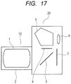
- FIG. 17 is a schematic diagram of a main part of a digital single-lens reflex camera (image pickup apparatus) having the zoom lens of the present invention mounted thereon.
- the zoom lens according to the present invention includes, in order from an object side to an image side: a first lens unit having a positive refractive power; a second lens unit having a negative refractive power; a third lens unit having a positive refractive power; a fourth lens unit having a positive refractive power; a fifth lens unit having a negative refractive power; and a rear lens group including one or more lens units.
- the third lens unit is configured to move toward the object side during zooming from a wide angle end (short focal length end) to a telephoto end (long focal length end), and an interval between each pair of adjacent lens units is changed during zooming.
- the fourth lens unit is configured to move in a direction having a vertical component with respect to an optical axis during image stabilization.
- FIG. 1 is a lens cross-sectional view of Embodiment 1 of the present invention when focused at an object at infinity at the wide angle end.
- FIG. 2A and FIG. 2B are aberration diagrams of Embodiment 1 when focused at an object at infinity at the wide angle end and the telephoto end, respectively.
- FIG. 3A and FIG. 3B are lateral aberration diagrams of Embodiment 1 when focused at an object at infinity at the wide angle end and the telephoto end, respectively.
- FIG. 4A and FIG. 4B are lateral aberration diagrams of Embodiment 1 after image stabilization for 0.3 degrees when focused at an object at infinity at the wide angle end and the telephoto end, respectively.
- a zoom lens of Embodiment 1 has a zoom ratio of 9.41 and an F-number of from 3.40 to 6.46.
- FIG. 5 is a lens cross-sectional view of Embodiment 2 of the present invention when focused at an object at infinity at the wide angle end.
- FIG. 6A and FIG. 6B are aberration diagrams of Embodiment 2 when focused at an object at infinity at the wide angle end and the telephoto end, respectively.
- FIG. 7A and FIG. 7B are lateral aberration diagrams of Embodiment 2 when focused at an object at infinity at the wide angle end and the telephoto end, respectively.
- FIG. 8A and FIG. 8B are lateral aberration diagrams of Embodiment 2 after image stabilization for 0.3 degrees when focused at an object at infinity at the wide angle end and the telephoto end, respectively.
- a zoom lens of Embodiment 2 has a zoom ratio of 8.46 and an F-number of from 3.51 to 6.47.
- FIG. 9 is a lens cross-sectional view of Embodiment 3 of the present invention when focused at an object at infinity at the wide angle end.
- FIG. 10A and FIG. 10B are aberration diagrams of Embodiment 3 when focused at an object at infinity at the wide angle end and the telephoto end, respectively.
- FIG. 11A and FIG. 11B are lateral aberration diagrams of Embodiment 3 when focused at an object at infinity at the wide angle end and the telephoto end, respectively.
- FIG. 12A and FIG. 12B are lateral aberration diagrams of Embodiment 3 after image stabilization for 0.3 degrees when focused at an object at infinity at the wide angle end and the telephoto end, respectively.
- a zoom lens of Embodiment 3 has a zoom ratio of 7.05 and an F-number of from 3.79 to 6.46.
- FIG. 13 is a lens cross-sectional view of Embodiment 4 of the present invention when focused at an object at infinity at the wide angle end.
- FIG. 14A and FIG. 14B are aberration diagrams of Embodiment 4 when focused at an object at infinity at the wide angle end and the telephoto end, respectively.
- FIG. 15A and FIG. 15B are lateral aberration diagrams of Embodiment 4 when focused at an object at infinity at the wide angle end and the telephoto end, respectively.
- FIG. 16A and FIG. 16B are lateral aberration diagrams of Embodiment 4 after image stabilization for 0.3 degrees when focused at an object at infinity at the wide angle end and the telephoto end, respectively.
- a zoom lens of Embodiment 4 has a zoom ratio of 7.05 and an F-number of from 3.73 to 6.47.
- FIG. 17 is a schematic diagram of a main part of a digital single-lens reflex camera (image pickup apparatus) having the zoom lens of the present invention mounted thereon.
- the zoom lens of the present invention is used as an image pickup optical system of image pickup apparatus such as a digital camera, a video camera, a broadcasting camera, a monitoring camera, and a silver-halide film camera.
- the zoom lens of the present invention may also be used as a projection optical system for a projection apparatus (projector).
- a zoom lens L 0 is illustrated in each of the lens cross-sectional views.
- the i-th lens unit is represented by Li.
- a rear lens group LR includes one or more lens units.
- An image stabilization unit IS is configured to move in the direction having the vertical component with respect to the optical axis during image stabilization.
- An aperture stop SP is also illustrated.
- An image plane IP corresponds to an image pickup surface of an image pickup element (photo-electric conversion element) such as a CCD sensor or a CMOS sensor when the zoom lens is used as an image pickup apparatus for a digital camera, a video camera, or the like.
- the image plane IP corresponds to a film surface.
- each lens unit is configured to move as indicated by the arrows.
- the arrow related to “Focus” indicates a movement direction of a focusing lens unit during focusing from infinity to close proximity.
- an F-number is represented by Fno.
- d indicates d-line (wavelength: 587.6 nm)
- g indicates g-line (wavelength: 435.8 nm).
- M indicates a meridional image plane at the d-line
- S indicates a sagittal image plane at the d-line.
- the distortion diagram is an illustration about the d-line.
- the lateral chromatic aberration diagram is an illustration about the g-line.
- a half angle of view (degree) is represented by ⁇ .
- the zoom lens of the present invention includes the following lens units, which are arranged in order from the object side to the image side: a first lens unit L 1 having a positive refractive power, a second lens unit L 2 having a negative refractive power, a third lens unit L 3 having a positive refractive power, a fourth lens unit L 4 having a positive refractive power, a fifth lens unit L 5 having a negative refractive power, and a rear lens group LR including one or more lens units.
- the third lens unit L 3 is configured to move toward the object side during zooming from the wide angle end to the telephoto end.
- the fourth lens unit L 4 is configured to move in the direction having the vertical component with respect to the optical axis during image stabilization.
- the fifth lens unit L 5 (focusing lens unit) is configured to move toward the image side during focusing from infinity to close proximity.
- an image blur is corrected by the fourth lens unit having a positive refractive power.
- a magnification can be effectively varied by the fifth lens unit having a negative refractive power, and it is easy to increase the zoom ratio while decreasing the entire system in size.
- a focal length of the third lens unit L 3 is represented by f3
- a focal length of the fourth lens unit L 4 is represented by f4.
- the following conditional expression is satisfied. 1.2 ⁇ f 4/ f 3 ⁇ 3.0 (1.0)
- Conditional Expression (1) is intended to effectively correct an image blur by the fourth lens unit L 4 , and appropriately adjust refractive power distribution between the positive refractive power of the third lens unit L 3 and the positive refractive power of the fourth lens unit L 4 , thereby reducing deterioration of optical performance due to a manufacturing tolerance of a lens unit having a positive refractive power.
- Conditional Expression (1) When the value exceeds the upper limit value of Conditional Expression (1), the refractive power of the fourth lens unit L 4 is too weak, and hence the decrease in optical performance due to the manufacturing tolerance of the third lens unit L 3 increases. Further, the image stabilization sensitivity of the fourth lens unit L 4 decreases, and hence the entire system increases in size in a radial direction thereof, which is not preferred.
- the value falls below the lower limit value of Conditional Expression (1) the positive refractive power of the fourth lens unit L 4 is too strong, with the result that the image stabilization sensitivity of the fourth lens unit L 4 increases, and decrease in optical performance during image stabilization increases. It is more preferred to set the numerical range of Conditional Expression (1) as follows. 1.25 ⁇ f 4/ f 3 ⁇ 1.8 (1A)
- the fourth lens unit L 4 may include three or less lenses. As the weight of the fourth lens unit L 4 for image stabilization increases, a mechanism for driving the lens unit increases in size, leading to increase in entire system in size. Thus, the fourth lens unit L 4 for image stabilization is preferably light.
- the fourth lens unit L 4 include three or less lenses.
- the fourth lens unit L 4 preferably includes three or less lenses including a positive lens and a negative lens.
- the fourth lens unit L 4 more preferably is constituted by a positive lens and a negative lens.
- an interval between the third lens unit L 3 and the fourth lens unit L 4 be narrower at the telephoto end than at the wide angle end.
- the third lens unit L 3 having a positive refractive power and the fourth lens unit L 4 having a positive refractive power are configured to move toward the object side to effectively move a principal point position of the entire system toward the object side during zooming from the wide angle end to the telephoto end.
- the fourth lens unit L 4 having a refractive power that is weaker than the refractive power of the third lens unit L 3 is configured to move during zooming more than the third lens unit L 3 . That is, the fourth lens unit L 4 is configured to move to narrow the interval between the third lens unit L 3 and the fourth lens unit L 4 so that a high zoom ratio may be effectively obtained while variation in spherical aberration during zooming is reduced.
- a curvature radius of a lens surface of the fourth lens unit L 4 that is closest to the object side is represented by R4a
- a curvature radius of a lens surface of the fourth lens unit L 4 that is closest to the image side is represented by R4b.
- a focal length of the fifth lens unit L 5 is represented by f5.
- a focal length of the entire system at the wide angle end is represented by fw.
- a focal length of the rear lens group LR at the wide angle end is represented by frw.
- a focal length of the first lens unit L 1 is represented by f1.
- a focal length of the second lens unit L 2 is represented by f2.
- Conditional Expressions (2) and (3) are intended to satisfactorily correct an image blur by the fourth lens unit L 4 .
- the curvature radii of the lens surfaces are large to some extent, an incident angle of a light beam entering the lens unit hardly changes during image stabilization, which is preferred.
- the curvature radii of the lens surfaces are too small, with the result that an incident angle of a light beam entering the fourth lens unit L 4 greatly changes during image stabilization, and the optical performance decreases during image stabilization, which is not preferred.
- Conditional Expression (4) is intended to appropriately set the refractive power of the fifth lens unit L 5 having a negative refractive power, thereby obtaining satisfactory optical performance over the entire zoom range while increasing the zoom ratio.
- the negative refractive power of the fifth lens unit L 5 is too weak (the absolute value of the negative refractive power is too small), with the result that a magnification effect of the fifth lens unit L 5 decreases, and it is difficult to increase the zoom ratio.
- Conditional Expression (5) more preferably satisfies Conditional Expression (5A). ⁇ 0.15 ⁇ fw/frw ⁇ 0.25 (5A)
- Conditional Expressions (6), (7), (8), and (9) are intended to optimize the refractive power of each of the first lens unit L 1 , the second lens unit L 2 , the third lens unit L 3 , and the fourth lens unit L 4 , thereby decreasing the entire system in size while suppressing aberration variation during zooming.
- the value exceeds the upper limit value of Conditional Expression (6) the positive refractive power of the first lens unit L 1 is too weak, and hence it is difficult to increase the zoom ratio.
- the positive refractive power of the first lens unit L 1 is too strong, and hence variation in spherical aberration during zooming increases, which is not preferred.
- a preferred focusing method may be the one that moves the fifth lens unit L 5 toward the image side during focusing from infinity to close proximity. It is demanded for digital cameras in recent years to be capable of photographing moving images, and thus image magnification changes due to focusing are demanded to be small. To fulfill this demand, it is preferred that a lens unit for focusing be arranged at a position close to an image plane, and the fifth lens unit L 5 is suitable for the lens unit for focusing in each Embodiment.
- the fifth lens unit L 5 is constituted by two lenses. In order to reduce aberration variation due to zooming and aberration variation due to focusing, and the thickness of the lens unit, thereby efficiently varying the magnification, it is preferred that the fifth lens unit L 5 include one positive lens and one negative lens.
- the zoom lens according to Embodiment 1 includes the following lens units, which are arranged in order from the object side to the image side: a first lens unit L 1 having a positive refractive power, a second lens unit L 2 having a negative refractive power, a third lens unit L 3 having a positive refractive power, a fourth lens unit L 4 having a positive refractive power, a fifth lens unit L 5 having a negative refractive power, a sixth lens unit L 6 having a negative refractive power, and a seventh lens unit L 7 having a positive refractive power.
- Embodiment 1 relates to a seven-unit zoom lens.
- the rear lens group LR includes the sixth lens unit L 6 having a negative refractive power and the seventh lens unit L 7 having a positive refractive power.
- the first lens unit L 1 , the second lens unit L 2 , the third lens unit L 3 , the fourth lens unit L 4 , the fifth lens unit L 5 , and the sixth lens unit L 6 are configured to move toward the object side during zooming from the wide angle end to the telephoto end.
- the seventh lens unit L 7 is configured not to move during zooming.
- the fourth lens unit L 4 is configured to move, as a whole, in the direction having the vertical component with respect to the optical axis, thereby correcting an image blur.
- the third lens unit L 3 having a positive refractive power is configured to move toward the object side to move the principal point of the entire system toward the object side during zooming from the wide angle end to the telephoto end.
- the zoom ratio easily increases.
- a ratio between the refractive power of the third lens unit L 3 and the refractive power of the fourth lens unit L 4 satisfies Conditional Expression (1).
- the image stabilization sensitivity is appropriately set while the positive refractive powers are effectively distributed, and decrease in optical performance due to the manufacturing tolerance is thus reduced.
- the fourth lens unit L 4 having a relatively weak positive refractive power is configured to move toward the object side by a larger amount than the third lens unit L 3 .
- the fourth lens unit L 4 is configured to move to narrow the interval between the third lens unit L 3 and the fourth lens unit L 4 so that variation in spherical aberration may be reduced while the zoom ratio increases.
- the fourth lens unit L 4 includes a positive lens and a negative lens, and the lens surface of the fourth lens unit L 4 that is closest to the object side and the lens surface thereof that is closest to the image side satisfy Conditional Expressions (2) and (3). With this, the zoom lens including an image stabilization drive mechanism is easily decreased in size and weight while the optical performance during image stabilization is satisfactorily maintained.
- the refractive power of the fifth lens unit L 5 satisfies Conditional Expression (4) to effectively increase the zoom ratio.
- the fifth lens unit L 5 includes the two lenses.
- the fifth lens unit L 5 is configured to move toward the image side during focusing from infinity to close proximity. With this, the lens unit for focusing decreases in weight, and a quiet drive is facilitated. Then, variation in image magnification during focusing is reduced so that the zoom lens may also be suitable for moving image photography.
- the rear lens group LR which includes the sixth lens unit L 6 and the seventh lens unit L 7 , has a combined focal length at the wide angle end that satisfies Conditional Expression (5). With this, the entire system is decreased in size while an incident angle of a light flux entering the image plane is restricted.
- the refractive power of the first lens unit L 1 satisfies Conditional Expression (6). With this, the entire system is decreased in size while variation in spherical aberration and variation in lateral chromatic aberration during zooming are suppressed.
- the refractive power of the second lens unit L 2 satisfies Conditional Expression (7). With this, the entire system is decreased in size while variation in spherical aberration, variation in lateral chromatic aberration, and variation in curvature of field during zooming are suppressed.
- the refractive power of the third lens unit L 3 satisfies Conditional Expression (8). With this, the entire system is decreased in size while variation in spherical aberration and variation in axial chromatic aberration during zooming are suppressed.
- the refractive power of the fourth lens unit L 4 satisfies Conditional Expression (9). With this, the entire system is decreased in size while variation in spherical aberration and variation in axial chromatic aberration during zooming are suppressed and the image stabilization sensitivity is appropriately set.
- the zoom lens of Embodiment 2 is the same as that of Embodiment 1 in zoom type including the number of lens units, the sign of the refractive power of each lens unit, and the like.
- the first lens unit L 1 , the second lens unit L 2 , the third lens unit L 3 , the fourth lens unit L 4 , the fifth lens unit L 5 , and the sixth lens unit L 6 are configured to move toward the object side during zooming from the wide angle end to the telephoto end.
- the seventh lens unit L 7 is configured not to move during zooming.
- a change in interval between each pair of lens units between the wide angle end and the telephoto end is the same as that of Embodiment 1.
- the optical action of each lens unit is also the same as that of Embodiment 1.
- the zoom lens according to Embodiment 3 includes the following lens units, which are arranged in order from the object side to the image side: a first lens unit L 1 having a positive refractive power, a second lens unit L 2 having a negative refractive power, a third lens unit L 3 having a positive refractive power, a fourth lens unit L 4 having a positive refractive power, a fifth lens unit L 5 having a negative refractive power, and a sixth lens unit L 6 having a positive refractive power.
- Embodiment 3 relates to a six-unit zoom lens.
- a rear lens group LR includes the sixth lens unit L 6 having a positive refractive power.
- the first lens unit L 1 , the third lens unit L 3 , the fourth lens unit L 4 , and the fifth lens unit L 5 are configured to move toward the object side, and the second lens unit L 2 is configured to move toward the image side along a locus convex to the image side during zooming from the wide angle end to the telephoto end.
- the sixth lens unit L 6 is configured not to move.
- the optical action of each lens unit from the first lens unit L 1 to the fifth lens unit L 5 is the same as that of Embodiment 1.
- the sixth lens unit L 6 satisfies Conditional Expression (5). With this, the entire system is decreased in size while an incident angle of a light flux entering the image plane is restricted.
- the zoom lens of Embodiment 4 includes the following lens units, which are arranged in order from the object side to the image side: a first lens unit L 1 having a positive refractive power, a second lens unit L 2 having a negative refractive power, a third lens unit L 3 having a positive refractive power, a fourth lens unit L 4 having a positive refractive power, a fifth lens unit L 5 having a negative refractive power, and a sixth lens unit L 6 having a negative refractive power.
- Embodiment 4 relates to a six-unit zoom lens.
- a rear lens group LR includes the sixth lens unit L 6 having a negative refractive power.
- the first lens unit L 1 , the third lens unit L 3 , the fourth lens unit L 4 , the fifth lens unit L 5 , and the sixth lens unit L 6 are configured to move toward the object side during zooming from the wide angle end to the telephoto end.
- the second lens unit L 2 is configured to move toward the object side along a locus convex to the image side.
- the optical action of each lens unit from the first lens unit L 1 to the fifth lens unit L 5 is the same as that of Embodiment 1.
- the sixth lens unit L 6 satisfies Conditional Expression (5). With this, the entire system is decreased in size while an incident angle of a light flux entering the image plane is restricted.
- an interchangeable lens 10 includes a zoom lens 1 according to any one of Embodiments 1 to 4.
- the zoom lens 1 is held by a lens barrel 2 , which is a holding member.
- a camera main body 20 includes a quick return mirror 3 , which is configured to reflect a light flux from the interchangeable lens 10 upward, and a focusing plate 4 , which is arranged in an image forming apparatus configured to form an image of the interchangeable lens 10 .
- the camera main body 20 also includes a penta roof prism 5 , which is configured to convert a reverse image formed on the focusing plate 4 into an erect image, an eyepiece lens 6 , which is used to observe the erect image, and other such components.
- an image pickup element such as a CCD sensor or a CMOS sensor configured to receive the image formed by the zoom lens, or a silver-halide film.
- the quick return mirror 3 is retracted from an optical path, and an image is formed on the photosensitive surface 7 by the interchangeable lens 10 .
- Embodiments 1 to 4 are effectively provided to the image pickup apparatus disclosed in this embodiment.
- the image pickup apparatus can also be similarly applied to a mirrorless single-lens reflex camera which does not include a quick return mirror 3 .
- Embodiments 1 to 4 Specific numerical data of Embodiments 1 to 4 are described below.
- i indicates the order from the object side
- ri indicates the curvature radius of an i-th optical surface (i-th surface)
- di indicates an on-axis interval between the i-th surface and an (i+1)th surface
- ndi and ⁇ di indicate the refractive index and Abbe number of a material of an optical member between the i-th surface and the (i+1)th surface with respect to the d-line, respectively.
- An aspherical shape is expressed by the following equation:
- X H 2 / R 1 + 1 - ( 1 + K ) ⁇ ( H / R ) 2 + A ⁇ ⁇ 4 ⁇ ⁇ H 4 + A ⁇ ⁇ 6 ⁇ H 6 + A ⁇ ⁇ 8 ⁇ H 8 + A ⁇ ⁇ 10 ⁇ ⁇ H 10
- the X-axis represents an optical axis direction
- the H-axis represents an axis in a direction perpendicular to the optical axis
- a traveling direction of light is positive
- R represents a paraxial curvature radius
- K represents a conic constant
- A4, A6, A8, and A10 represent aspherical coefficients, respectively.
- a symbol * assigned to a surface number indicates a surface having an aspherical shape.
- the notation “e-x” indicates ⁇ 10 ⁇ x .
- the notation “BF” indicates an air-equivalent back focus.
- the total lens length is a value obtained by adding a value of the back focus BF to a distance from the first lens surface to the last lens surface.
- Table 1 a relationship between each of the conditional expressions given above and the numerical data is shown in Table 1.
Landscapes
- Physics & Mathematics (AREA)
- General Physics & Mathematics (AREA)
- Optics & Photonics (AREA)
- Nonlinear Science (AREA)
- Lenses (AREA)
Applications Claiming Priority (2)
| Application Number | Priority Date | Filing Date | Title |
|---|---|---|---|
| JP2016-093106 | 2016-05-06 | ||
| JP2016093106A JP6818429B2 (ja) | 2016-05-06 | 2016-05-06 | ズームレンズ及びそれを有する撮像装置 |
Publications (2)
| Publication Number | Publication Date |
|---|---|
| US20170322399A1 US20170322399A1 (en) | 2017-11-09 |
| US10545320B2 true US10545320B2 (en) | 2020-01-28 |
Family
ID=60243977
Family Applications (1)
| Application Number | Title | Priority Date | Filing Date |
|---|---|---|---|
| US15/581,360 Active US10545320B2 (en) | 2016-05-06 | 2017-04-28 | Zoom lens and image pickup apparatus including the same |
Country Status (2)
| Country | Link |
|---|---|
| US (1) | US10545320B2 (enExample) |
| JP (1) | JP6818429B2 (enExample) |
Families Citing this family (14)
| Publication number | Priority date | Publication date | Assignee | Title |
|---|---|---|---|---|
| JP6604918B2 (ja) * | 2016-08-04 | 2019-11-13 | キヤノン株式会社 | ズームレンズ及びそれを有する撮像装置 |
| US11175485B2 (en) * | 2016-11-21 | 2021-11-16 | Nikon Corporation | Zoom optical system, optical apparatus, imaging apparatus and method for manufacturing the zoom optical system |
| US11269164B2 (en) | 2016-11-21 | 2022-03-08 | Nikon Corporation | Zoom optical system, optical apparatus, imaging apparatus and method for manufacturing the zoom optical system |
| JP6818546B2 (ja) | 2016-12-28 | 2021-01-20 | キヤノン株式会社 | ズームレンズ及びそれを有する撮像装置 |
| JP6942496B2 (ja) | 2017-03-23 | 2021-09-29 | キヤノン株式会社 | ズームレンズ及びそれを有する撮像装置 |
| JP6953155B2 (ja) | 2017-03-23 | 2021-10-27 | キヤノン株式会社 | ズームレンズ及びそれを有する撮像装置 |
| JP6980430B2 (ja) * | 2017-06-28 | 2021-12-15 | キヤノン株式会社 | ズームレンズ及びそれを有する撮像装置 |
| CN118818740A (zh) | 2017-09-11 | 2024-10-22 | 株式会社尼康 | 变倍光学系统以及光学装置 |
| JPWO2019097716A1 (ja) * | 2017-11-20 | 2020-11-19 | 株式会社ニコン | 変倍光学系、光学装置、および変倍光学系の製造方法 |
| JP7146601B2 (ja) | 2018-12-03 | 2022-10-04 | キヤノン株式会社 | 光学系およびそれを有する撮像装置 |
| JP7006814B2 (ja) * | 2019-01-31 | 2022-01-24 | 株式会社ニコン | 変倍光学系および光学機器 |
| JP7413044B2 (ja) * | 2020-01-27 | 2024-01-15 | キヤノン株式会社 | ズームレンズおよびそれを有する撮像装置、撮像システム |
| JP7577460B2 (ja) * | 2020-05-14 | 2024-11-05 | 株式会社タムロン | ズームレンズ及び撮像装置 |
| JP7739076B2 (ja) * | 2021-07-27 | 2025-09-16 | キヤノン株式会社 | ズームレンズ及びそれを有する撮像装置、撮像システム |
Citations (21)
| Publication number | Priority date | Publication date | Assignee | Title |
|---|---|---|---|---|
| US6061180A (en) * | 1996-10-29 | 2000-05-09 | Canon Kabushiki Kaisha | Zoom lens |
| JP2005242015A (ja) | 2004-02-26 | 2005-09-08 | Canon Inc | ズームレンズ及びそれを有する撮像装置 |
| US20060268428A1 (en) * | 2005-04-25 | 2006-11-30 | Sony Corporation | Zoom lens and image pickup apparatus |
| JP2010015003A (ja) | 2008-07-04 | 2010-01-21 | Nikon Corp | 変倍光学系、この変倍光学系を備えた光学機器、及び、変倍光学系の変倍方法 |
| US20100220400A1 (en) * | 2009-01-30 | 2010-09-02 | Nikon Corporation | Zoom lens, optical apparatus equipped therewith and method for manufacturing the zoom lens |
| JP2012141555A (ja) | 2011-01-06 | 2012-07-26 | Nikon Corp | 変倍光学系、この変倍光学系を備える光学機器、及び、変倍光学系の製造方法 |
| US20130120640A1 (en) * | 2011-11-16 | 2013-05-16 | Canon Kabushiki Kaisha | Zoom lens and image pickup apparatus including the same |
| US20140211029A1 (en) * | 2013-01-30 | 2014-07-31 | Canon Kabushiki Kaisha | Zoom lens and image pickup apparatus including the same |
| US20140240554A1 (en) * | 2013-02-22 | 2014-08-28 | Panasonic Corporation | Zoom lens system, interchangeable lens apparatus and camera system |
| US20140362259A1 (en) * | 2013-06-10 | 2014-12-11 | Konica Minolta, Inc. | Variable-Magnification Optical System, Imaging Optical Device, And Digital Appliance |
| US9110278B2 (en) | 2012-11-06 | 2015-08-18 | Canon Kabushiki Kaisha | Zoom lens and image pickup apparatus including same |
| US20160018630A1 (en) * | 2013-03-27 | 2016-01-21 | Fujifilm Corporation | Zoom lens and imaging apparatus |
| US9250424B2 (en) | 2012-11-22 | 2016-02-02 | Canon Kabushiki Kaisha | Zoom lens and image-pickup apparatus |
| US9268119B2 (en) | 2013-01-11 | 2016-02-23 | Canon Kabushiki Kaisha | Zoom lens and image pickup apparatus including the same |
| US9268118B2 (en) | 2012-10-30 | 2016-02-23 | Canon Kabushiki Kaisha | Zoom lens and image-pickup apparatus |
| US20160131879A1 (en) | 2014-11-06 | 2016-05-12 | Canon Kabushiki Kaisha | Zoom lens and image pickup apparatus including the same |
| US20160209632A1 (en) * | 2015-01-21 | 2016-07-21 | Panasonic Intellectual Property Management Co., Ltd. | Zoom lens system, interchangeable lens device, and camera system |
| US9465203B2 (en) | 2013-11-22 | 2016-10-11 | Canon Kabushiki Kaisha | Zoom lens and image pickup apparatus including the same |
| US9575391B2 (en) | 2014-03-31 | 2017-02-21 | Canon Kabushiki Kaisha | Zoom lens and image pickup apparatus including the same |
| US9638904B2 (en) | 2014-04-01 | 2017-05-02 | Canon Kabushiki Kaisha | Zoom lens and image pickup apparatus including the same |
| US20170242228A1 (en) | 2016-02-24 | 2017-08-24 | Canon Kabushiki Kaisha | Zoom lens and image pickup apparatus including the same |
Family Cites Families (2)
| Publication number | Priority date | Publication date | Assignee | Title |
|---|---|---|---|---|
| JP6127462B2 (ja) * | 2012-11-14 | 2017-05-17 | 株式会社ニコン | 変倍光学系、光学装置 |
| JP6364857B2 (ja) * | 2013-03-29 | 2018-08-01 | 株式会社シグマ | 防振機能を備えた変倍結像光学系 |
-
2016
- 2016-05-06 JP JP2016093106A patent/JP6818429B2/ja active Active
-
2017
- 2017-04-28 US US15/581,360 patent/US10545320B2/en active Active
Patent Citations (22)
| Publication number | Priority date | Publication date | Assignee | Title |
|---|---|---|---|---|
| US6061180A (en) * | 1996-10-29 | 2000-05-09 | Canon Kabushiki Kaisha | Zoom lens |
| JP2005242015A (ja) | 2004-02-26 | 2005-09-08 | Canon Inc | ズームレンズ及びそれを有する撮像装置 |
| US20060119939A1 (en) * | 2004-02-26 | 2006-06-08 | Canon Kabushiki Kaisha | Zoom lens system and imaging apparatus having the same |
| US20060268428A1 (en) * | 2005-04-25 | 2006-11-30 | Sony Corporation | Zoom lens and image pickup apparatus |
| JP2010015003A (ja) | 2008-07-04 | 2010-01-21 | Nikon Corp | 変倍光学系、この変倍光学系を備えた光学機器、及び、変倍光学系の変倍方法 |
| US20100220400A1 (en) * | 2009-01-30 | 2010-09-02 | Nikon Corporation | Zoom lens, optical apparatus equipped therewith and method for manufacturing the zoom lens |
| JP2012141555A (ja) | 2011-01-06 | 2012-07-26 | Nikon Corp | 変倍光学系、この変倍光学系を備える光学機器、及び、変倍光学系の製造方法 |
| US20130120640A1 (en) * | 2011-11-16 | 2013-05-16 | Canon Kabushiki Kaisha | Zoom lens and image pickup apparatus including the same |
| US9268118B2 (en) | 2012-10-30 | 2016-02-23 | Canon Kabushiki Kaisha | Zoom lens and image-pickup apparatus |
| US9110278B2 (en) | 2012-11-06 | 2015-08-18 | Canon Kabushiki Kaisha | Zoom lens and image pickup apparatus including same |
| US9250424B2 (en) | 2012-11-22 | 2016-02-02 | Canon Kabushiki Kaisha | Zoom lens and image-pickup apparatus |
| US9268119B2 (en) | 2013-01-11 | 2016-02-23 | Canon Kabushiki Kaisha | Zoom lens and image pickup apparatus including the same |
| US20140211029A1 (en) * | 2013-01-30 | 2014-07-31 | Canon Kabushiki Kaisha | Zoom lens and image pickup apparatus including the same |
| US20140240554A1 (en) * | 2013-02-22 | 2014-08-28 | Panasonic Corporation | Zoom lens system, interchangeable lens apparatus and camera system |
| US20160018630A1 (en) * | 2013-03-27 | 2016-01-21 | Fujifilm Corporation | Zoom lens and imaging apparatus |
| US20140362259A1 (en) * | 2013-06-10 | 2014-12-11 | Konica Minolta, Inc. | Variable-Magnification Optical System, Imaging Optical Device, And Digital Appliance |
| US9465203B2 (en) | 2013-11-22 | 2016-10-11 | Canon Kabushiki Kaisha | Zoom lens and image pickup apparatus including the same |
| US9575391B2 (en) | 2014-03-31 | 2017-02-21 | Canon Kabushiki Kaisha | Zoom lens and image pickup apparatus including the same |
| US9638904B2 (en) | 2014-04-01 | 2017-05-02 | Canon Kabushiki Kaisha | Zoom lens and image pickup apparatus including the same |
| US20160131879A1 (en) | 2014-11-06 | 2016-05-12 | Canon Kabushiki Kaisha | Zoom lens and image pickup apparatus including the same |
| US20160209632A1 (en) * | 2015-01-21 | 2016-07-21 | Panasonic Intellectual Property Management Co., Ltd. | Zoom lens system, interchangeable lens device, and camera system |
| US20170242228A1 (en) | 2016-02-24 | 2017-08-24 | Canon Kabushiki Kaisha | Zoom lens and image pickup apparatus including the same |
Also Published As
| Publication number | Publication date |
|---|---|
| US20170322399A1 (en) | 2017-11-09 |
| JP2017201365A (ja) | 2017-11-09 |
| JP6818429B2 (ja) | 2021-01-20 |
Similar Documents
| Publication | Publication Date | Title |
|---|---|---|
| US10545320B2 (en) | Zoom lens and image pickup apparatus including the same | |
| US10627610B2 (en) | Zoom lens and image pickup apparatus | |
| US9684155B2 (en) | Optical system and image pickup apparatus including the same | |
| US10073252B2 (en) | Optical system and image pickup apparatus including the same | |
| US9509912B2 (en) | Zoom lens and image pickup apparatus including the same | |
| US9638904B2 (en) | Zoom lens and image pickup apparatus including the same | |
| US9134512B2 (en) | Zoom lens and image pickup apparatus having the same | |
| US9223119B2 (en) | Zoom lens and image pickup apparatus having the same | |
| US9219864B2 (en) | Zoom lens and image pickup apparatus including the same | |
| US10754169B2 (en) | Optical system and image pickup apparatus including the same | |
| US10120170B2 (en) | Zoom lens and image pickup apparatus including the same | |
| US11131829B2 (en) | Zoom lens and image pickup apparatus | |
| US8437090B2 (en) | Zoom lens and image pickup apparatus including the same | |
| US10718930B2 (en) | Fixed focal length lens and image pickup apparatus | |
| US11703661B2 (en) | Optical system and optical apparatus | |
| US9207438B2 (en) | Zoom lens and image pick-up apparatus having the same | |
| US20120113516A1 (en) | Zoom lens and image pickup apparatus including the same | |
| US10353186B2 (en) | Zoom lens and image pickup apparatus including the same | |
| US9557543B2 (en) | Zoom lens and image pickup apparatus including the same | |
| US10663703B2 (en) | Zoom lens and image pickup apparatus | |
| US8792181B2 (en) | Zoom lens and image pickup apparatus including the same | |
| US9995918B2 (en) | Zoom lens and image pickup apparatus including the same | |
| US10495861B2 (en) | Zoom lens and image pickup apparatus | |
| US10571670B2 (en) | Zoom lens and image pickup apparatus including the same | |
| US9151935B2 (en) | Zoom lens and image pickup apparatus including the same |
Legal Events
| Date | Code | Title | Description |
|---|---|---|---|
| AS | Assignment |
Owner name: CANON KABUSHIKI KAISHA, JAPAN Free format text: ASSIGNMENT OF ASSIGNORS INTEREST;ASSIGNOR:SUGITA, SHIGENOBU;REEL/FRAME:043457/0872 Effective date: 20170410 |
|
| STPP | Information on status: patent application and granting procedure in general |
Free format text: FINAL REJECTION MAILED |
|
| STPP | Information on status: patent application and granting procedure in general |
Free format text: RESPONSE AFTER FINAL ACTION FORWARDED TO EXAMINER |
|
| STPP | Information on status: patent application and granting procedure in general |
Free format text: ADVISORY ACTION MAILED |
|
| STPP | Information on status: patent application and granting procedure in general |
Free format text: DOCKETED NEW CASE - READY FOR EXAMINATION |
|
| STPP | Information on status: patent application and granting procedure in general |
Free format text: NOTICE OF ALLOWANCE MAILED -- APPLICATION RECEIVED IN OFFICE OF PUBLICATIONS |
|
| STPP | Information on status: patent application and granting procedure in general |
Free format text: PUBLICATIONS -- ISSUE FEE PAYMENT RECEIVED |
|
| STCF | Information on status: patent grant |
Free format text: PATENTED CASE |
|
| MAFP | Maintenance fee payment |
Free format text: PAYMENT OF MAINTENANCE FEE, 4TH YEAR, LARGE ENTITY (ORIGINAL EVENT CODE: M1551); ENTITY STATUS OF PATENT OWNER: LARGE ENTITY Year of fee payment: 4 |