US10528005B2 - Mechanism for a timepiece and timepiece having such a mechanism - Google Patents
Mechanism for a timepiece and timepiece having such a mechanism Download PDFInfo
- Publication number
- US10528005B2 US10528005B2 US15/534,852 US201515534852A US10528005B2 US 10528005 B2 US10528005 B2 US 10528005B2 US 201515534852 A US201515534852 A US 201515534852A US 10528005 B2 US10528005 B2 US 10528005B2
- Authority
- US
- United States
- Prior art keywords
- energy distribution
- elastic
- blocking
- blocking member
- monostable
- Prior art date
- Legal status (The legal status is an assumption and is not a legal conclusion. Google has not performed a legal analysis and makes no representation as to the accuracy of the status listed.)
- Active
Links
Images


Classifications
-
- G—PHYSICS
- G04—HOROLOGY
- G04B—MECHANICALLY-DRIVEN CLOCKS OR WATCHES; MECHANICAL PARTS OF CLOCKS OR WATCHES IN GENERAL; TIME PIECES USING THE POSITION OF THE SUN, MOON OR STARS
- G04B17/00—Mechanisms for stabilising frequency
- G04B17/04—Oscillators acting by spring tension
- G04B17/045—Oscillators acting by spring tension with oscillating blade springs
-
- G—PHYSICS
- G04—HOROLOGY
- G04B—MECHANICALLY-DRIVEN CLOCKS OR WATCHES; MECHANICAL PARTS OF CLOCKS OR WATCHES IN GENERAL; TIME PIECES USING THE POSITION OF THE SUN, MOON OR STARS
- G04B1/00—Driving mechanisms
- G04B1/10—Driving mechanisms with mainspring
- G04B1/22—Compensation of changes in the motive power of the mainspring
- G04B1/225—Compensation of changes in the motive power of the mainspring with the aid of an interposed power-accumulator (secondary spring) which is always tensioned
-
- G—PHYSICS
- G04—HOROLOGY
- G04B—MECHANICALLY-DRIVEN CLOCKS OR WATCHES; MECHANICAL PARTS OF CLOCKS OR WATCHES IN GENERAL; TIME PIECES USING THE POSITION OF THE SUN, MOON OR STARS
- G04B15/00—Escapements
- G04B15/06—Free escapements
Definitions
- the invention relates to mechanisms for timepieces and to timepieces having such mechanisms.
- Document U.S. Pat. No. 8,303,167B2 discloses a mechanism for a timepiece, comprising a regulator mechanism having a periodical movement, two rotary escapement wheels, a blocking mechanism cooperating with the escapement wheels, said distributor mechanism being controlled by the regulator mechanism to regularly and alternatively hold and release the escapement wheels so that said escapement wheels rotate step by step, and an bistable elastic member configured to be cyclically deformed in a predetermined way to store energy, and to release this energy to the regulator mechanism by elastic return.
- This mechanism is very complex, hence costly, and includes a large number of parts moving with frictional losses, which limits the energetic efficiency of the system.
- One objective of the present invention is to at least mitigate these drawbacks.
- a mechanism for a timepiece comprising:
- the mechanism is simpler in structure and way of operating, thus less costly, more reliable and better in terms of energetic efficiency.
- the invention also concerns a timepiece having a mechanism as defined above.
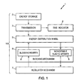
- FIG. 1 is a schematic bloc diagram of a mechanical timepiece, according to the invention.
- FIG. 2 is a plan view of a mechanism for a mechanical timepiece, including a regulator mechanism, a blocking mechanism and an energy distribution wheel according to a first embodiment of the invention
- FIG. 2 a shows details of the blocking mechanism and energy distribution wheel of FIG. 2 ;
- FIGS. 3,3 a to 9 , 9 a are views similar to FIGS. 2 and 2 a , respectively illustrating successive movements of the mechanism of FIG. 2 in substantially half a period of the regulating mechanism;
- FIGS. 10-12 are views similar to FIG. 2 , respectively for second, third and fourth embodiments of the invention.
- FIGS. 13, 13 a - 20 , 20 a are views similar to FIGS. 2, 2 a - 9 , 9 a , in a fifth embodiment of the invention.
- FIG. 1 shows a schematic bloc diagram of a mechanical timepiece 1 , for instance a watch, including at least the following:
- the energy distribution member may be a rotary energy distribution wheel 5 .
- the following description will be made with respect to such energy distribution wheel.
- the mechanical energy storage 2 is usually a spring, for instance a spiral shaped spring usually called main spring.
- This spring may be wound manually through a winding stem and/or automatically through an automatic winding powered by the movements of the user.
- the transmission 3 is usually a gear comprising a series of gear wheels (not shown) meshing with one another and connecting an input shaft to an output shaft (not shown).
- the input shaft is powered by the mechanical energy storage 2 and the output shaft is connected to the energy distribution wheel.
- Some of the gear wheels are connected to the watch hands or other time indicators 4 .
- the transmission 3 is designed so that the energy distribution wheel rotates much more quickly than the input shaft (with a speed ratio which may be for instance of the order of 3000).
- the regulator mechanism 7 is designed to oscillate with a constant frequency, thus ensuring the timepiece's precision.
- the oscillation of the regulator is sustained by regular transfers of mechanical energy from the energy distribution wheel 5 , through a monostable elastic member 9 which may for instance belong to the blocking mechanism 6 .
- the mechanical energy storage 2 , transmission 3 , energy distribution wheel 5 , blocking mechanism 6 and regulator 7 form together a timepiece movement 10 .
- FIGS. 2-9 The particular embodiment of FIGS. 2-9 will now be described in details.
- the blocking mechanism 6 and regulator mechanism 7 may be monolithic and made in a single plate 11 , as shown for instance in FIGS. 2 and 2 a .
- Plate 11 is usually planar.
- the plate 11 may have a small thickness, e.g. about 0.1 to about 0.6 mm, depending of the material thereof.
- the plate 11 may have transversal dimensions, in the plane of said plate (e.g. width and length, or diameter), comprised between about 15 mm and 40 mm.
- the plate 11 may be manufactured in any suitable material, preferably having a relatively high Young modulus to exhibit good elastic properties. Examples of materials usable for plate 11 are: silicon, nickel, steel, titanium. In the case of silicon, the thickness of plate 11 may be for instance comprised between 0.3 and 0.6 mm.
- the various members of the blocking mechanism 6 and regulator mechanism 7 which will be detailed hereafter, are formed by making cutouts in plate 11 . These cutouts may be formed by any manufacturing method known in micromechanics, in particular for the manufacture of MEMS.
- plate 11 may be locally hollowed out for instance by Deep Reactive Ion Etching (DRIE), or in some cases by solid state laser cutting (in particular for prototyping or small series).
- DRIE Deep Reactive Ion Etching
- solid state laser cutting in particular for prototyping or small series.
- the blocking mechanism 6 and regulator mechanism 7 may be obtained for instance by LIGA.
- plate 11 may be locally hollowed out for instance by Wire Electric Discharge Machining (WEDM).
- WEDM Wire Electric Discharge Machining
- the constituting parts of the blocking mechanism 6 and regulator mechanism 7 each formed by portions of plate 11 , by will now be described in details.
- Some of these parts are rigid and others are elastically deformable, usually in flexion.
- the difference between so-called rigid parts and so-called elastic parts is their rigidity in the plane of plate 11 , due to their shape and in particular to their slenderness. Slenderness may be measured for instance by the slenderness ratio (ratio of length of the part on width of the part).
- Parts of high slenderness are elastic (i.e. elastically deformable) and parts of low slenderness are rigid.
- so-called rigid parts may have a rigidity in the plane of plate 11 , which is at least about 1000 times higher than the rigidity of so-called elastic parts in the plane of plate 11 .
- Typical dimensions for the elastic connections, e.g. elastic branches 21 , 33 and elastic links 27 described below, include a length comprised for instance between 5 and 13 mm, and a width comprised for instance between 0.01 mm (10 ⁇ m) and 0.04 mm (40 ⁇ m), e.g. around 0.025 mm (25 ⁇ m).
- Plate 11 forms an outer frame which is fixed to a support plate 11 a for instance by screws or similar through holes 11 b of the plate 11 .
- the support plate 11 a is in turn fixed in the timepiece casing.
- plate 11 forms a closed, rigid frame entirely surrounding the blocking mechanism 6 and regulator mechanism 7 , but this frame could be designed otherwise and in particular could be designed to not surround or not surround totally the blocking mechanism 6 and regulator mechanism 7 .
- such fixed frame includes two substantially parallel sides 12 , 15 extending in a first direction X and two substantially parallel sides 13 , 14 extending in a second direction Y which is substantially perpendicular to the first direction X.
- Frame 12 - 15 , support plate 11 a and all other fixed parts may be referred to herein as “a support”.
- the energy distribution wheel 5 is pivotally mounted relative to the support, around an axis of rotation Z which is perpendicular to the plate 11 .
- the energy distribution wheel 5 is biased by energy storage 2 through transmission 3 in a single direction of rotation 36 .
- the energy distribution wheel 5 has external teeth 5 a , each having a front face 5 b facing the direction of rotation 36 and a rear face 5 c opposite the direction of rotation 36 .
- the front face 5 b can extend in a radial plane which is parallel to the rotation axis Z, while the rear face 5 c may extend parallel to axis Z and slantwise relative to the radial direction (see FIG. 2 a ).
- teeth 5 a do not need to have the complex shape of a classical escapement wheel of a so-called Swiss-lever escapement or Swiss-anchor escapement.
- the monostable elastic member 9 is linked to the regulator mechanism 7 and is adapted to bear on the teeth 5 a of the energy distribution wheel 5 .
- the monostable elastic member 9 normally has a first geometrical configuration (rest position) and the teeth 5 a of the energy distribution wheel are adapted to elastically deform said monostable elastic member 9 by cam effect from said first geometrical configuration to a second geometrical configuration.
- the monostable elastic member 9 is arranged such that during each rotation cycle of the energy distribution wheel 5 :
- the regulator mechanism may have a rigid, inertial regulating member 17 which is connected to the frame of the plate 11 by a first elastic suspension 21 .
- the first elastic suspension may comprise for instance two flexible, first elastic branches 21 extending substantially parallel to the second direction Y, from the side 12 of the plate 11 so that the regulating member 17 is movable in translation substantially parallel to the first direction X with respect to the support.
- the regulating member 17 and the first elastic suspension 21 are arranged so that said regulating member 17 oscillates in two directions from the neutral position shown on FIG. 2 , according to the double arrow 17 a visible on FIG. 2 , between two extreme positions which will be called here “first and second extreme regulating member positions”.
- the translation movement of regulating member 17 may be substantially rectilinear.
- the regulating member 17 is mounted on the support to oscillate in circular translation, with a first amplitude of oscillation in the first direction X and a non-zero, second amplitude of oscillation in the second direction Y.
- the first amplitude of oscillation is at least 10 times the second amplitude, which makes the movement substantially rectilinear.
- the regulating member 17 may have a main rigid body 18 extending longitudinally substantially parallel to the first direction X close to the side 12 of plate 11 , two diverging rigid arms 19 extending from the ends of the main body 18 toward the side 15 of plate 11 , up to respective free ends 20 .
- the free ends 20 may extend outwardly opposite to each other, substantially parallel to the first direction X.
- the first elastic branches 21 may have first ends connected to the side 12 of plate 11 , respectively close to sides 13 , 14 of plate 11 , and second ends respectively connected to the free ends 20 of the arms 19 .
- the first elastic branches 21 may be substantially rectilinear (i.e. not flexed) when the regulating member 17 is at rest in the neutral position.
- first elastic branches 21 and the amplitude of oscillation of regulating member 17 are such that the movement of said regulating member 17 is substantially rectilinear, as explained above.
- the blocking mechanism 6 has a rigid blocking member 8 which is connected to the regulating member 17 by at least an elastic link 27 so as to move in synchronism with said regulating member 17 .
- the blocking member may be connected to the regulating member 17 by two flexible elastic links 27 extending substantially parallel to the second direction Y.
- Said flexible elastic links 27 may be arranged to be substantially rectilinear (non-flexed) when the regulating member 17 is in neutral position.
- the blocking member 8 may be mounted on the frame of the plate 11 by a second elastic suspension 33 .
- the second elastic suspension 33 may be arranged to impose a translational movement to the blocking member 8 in the second direction Y.
- the second elastic suspension may comprise two flexible, second elastic branches 33 extending substantially parallel to the first direction X, so that blocking member 8 is movable in translation substantially parallel to the second direction Y, in direction of double arrows 8 a .
- the blocking member is thus movable in two opposite directions from a neutral position, between two extreme positions called here “first and second extreme blocking member positions”.
- the elastic branches 33 may be arranged so as to be substantially rectilinear (not flexed) when the blocking member 8 is at rest in the neutral position.
- the blocking member 8 may include:
- the elastic links 27 may have first ends connected to main body 18 of regulating member 17 , close to the ends thereof, and second ends respectively connected to the free ends 24 , 26 of the arms 23 , 25 .
- the free end 26 of the lateral arm 25 may be extended toward the other lateral arm 23 , in the first direction X, by a first transversal, rigid arm 30 .
- the lateral arm 25 may also be extended, toward the other lateral arm 23 , in the first direction X, by a second rigid transversal arm 28 which is close to the base 22 .
- the energy distribution wheel 5 is between first and second transversal arms 30 , 28 .
- first and second transversal arms 30 , 28 may have respectively first and second stop members 29 a , 29 b .
- First and second stop members 29 a , 29 b may be in the form of rigid fingers protruding toward each other from the free ends of first and second transversal arms 30 , 28 , in the second direction Y.
- First and second stop members 29 a , 29 b are designed to cooperate with the teeth 5 a of the energy distribution wheel 5 , as will be explained in more details below, to alternately hold and release said energy distribution wheel 5 .
- First and second stop members 29 a , 29 b may have a stop face, respectively 29 a 1 , 29 b 1 , facing the front face 5 b of the teeth, and an opposite rear face, respectively 29 a 2 , 29 b 2 .
- the stop faces 29 a 1 , 29 b 1 may preferably be disposed in a radial plane parallel to axis Z, while the rear faces 29 a 2 , 29 b 2 may extend slantwise so that the stop members 29 a , 29 b have pointed shapes.
- Blocking member 8 may further include a strut 25 a , extending in the second direction Y and joining the lateral arm 25 to the first transversal arm 30 .
- Blocking member 8 may further have a tab 31 extending in the second direction Y from the transversal arm 30 , toward the side 15 of plate 11 .
- the free end 26 and first transversal arm 30 may be received with small play in an indent 26 a cut out in the side 25 of plate 11 .
- tab 31 may be received in a further indent 31 a cut out in the side 15 of plate 11 .
- Plate 11 may further include a rigid tongue 16 , extending in the second direction Y from the side 15 of plate 11 toward side 12 , between the energy distribution wheel 5 and the lateral arm 23 of the blocking member 8 .
- Tongue 16 may have a first edge 16 a facing the energy distribution wheel 5 and extending parallel to the second direction Y.
- the first edge 16 a may have a concave, circular cut out 16 b partly receiving the energy distribution wheel 5 .
- Tongue 16 further has a second edge 16 c opposite the first edge and facing the lateral arm 23 .
- the second edge 16 c may be slanted parallel to the lateral arm 23 , and be in close vicinity to lateral arm 23 .
- One of the second elastic branches 33 may have a first end connected to the first edge 16 a of the tongue 16 , close to the side 15 of plate 11 , and a second end connected to the tab 31 .
- the other of the second elastic branches 33 may have a first end connected to the first edge 16 a of the tongue 16 , close to the free end of the tongue 16 , and a second end connected to the lateral arm 25 close to the base 22 .
- the blocking member 8 may be connected to the monostable elastic member 9 .
- said monostable elastic member may be a flexible tongue 9 which has a first end connected to the blocking member 8 (and therefore linked to the regulator mechanism 7 through flexible links 27 ) and a second, free end bearing on the teeth 5 a of the energy distribution wheel 5 .
- Typical dimensions for the flexible tongue 9 include a length comprised between for instance 3 and 5 mm, and a width comprised for instance between 0.01 mm (10 ⁇ m) and 0.04 mm (40 ⁇ m), for instance around 0.025 mm (25 ⁇ m).
- the flexible tongue 9 may be mounted on the blocking member 8 adjacent the second stop member 29 b .
- the flexible tongue may be connected to the lateral arm 25 of the blocking member 8 , close to the transversal arm 28 .
- the flexible tongue 9 may extend substantially parallel to the first direction X, between the transversal arm 28 and the energy distribution wheel 5 , up to a free end which is close to the second stop member 29 b.
- the flexible tongue 9 and blocking member 8 being two distinct members, the mechanism thus provides a separation between the function of blocking/releasing the distribution wheel 5 (provided by the blocking member 8 ) and the function of transferring energy to the regulator mechanism to sustain oscillation thereof (provided by the flexible tongue 9 ). Thanks to this separation of functions, the design of the blocking member 8 doesn't need to take into account the function of transferring energy (as it is the case in a traditional Swiss-anchor escapement which handles both blocking and energy transferring functions) and the design of the flexible tongue 9 doesn't need to take into account the function of blocking/releasing the distribution wheel 5 .
- regulating member 17 oscillates in translation parallel to the first direction X, with a frequency f comprised for instance between 20 and 30 Hz, and blocking member 8 oscillates with a frequency 2 f , twice the oscillation frequency of the regulating member 17 .
- the elastic links 27 are arranged such that:
- first and second stop members 29 a , 29 b move substantially radially with regard to the energy distribution wheel 5 , alternately toward and away from said energy distribution wheel, and the first and second stop members 29 a , 29 b thus interfere in turn with the teeth 5 a of the energy distribution wheel 5 so as to hold said energy distribution wheel 5 respectively when said blocking member 8 is in the first and second extreme blocking member positions.
- the first stop member 29 a is arranged to:
- the second stop member 29 b is arranged to:
- the second escape position of blocking member 8 may be between the first extreme blocking member position (close to side 12 ) and the first escape position.
- the first and second stop members 29 a , 29 b are arranged such that:
- the flexible tongue 9 may be arranged such that the teeth 5 a of the energy distribution wheel 5 elastically deform said monostable elastic member 9 from said first geometrical configuration to said second geometrical configuration during rotation of the energy distribution wheel 5 when the blocking member 8 is between the first escape position and the second extreme blocking member position.
- the flexible tongue 9 accumulates a predetermined potential mechanical energy, corresponding to the geometrical deformation thereof between the predetermined first geometrical configuration and the predetermined second geometrical configuration. This predetermined energy is the same at each rotation cycle of the energy distribution wheel 5 .
- the flexible tongue 9 may be arranged such that said flexible tongue 9 is in the second geometrical configuration when the blocking member 8 is in the second extreme blocking member position. Thus, the flexible tongue 9 returns to the first geometric configuration and transfers said predetermined amount of mechanical energy to the blocking member 8 during movement of the blocking member 8 from the second extreme blocking member position to the second escape position.
- the elastic links 27 are arranged to transmit said predetermined amount of mechanical energy to the regulating member 17 .
- the flexible tongue 9 may be arranged not to interfere with the teeth 5 a of the energy distribution wheel 5 while the blocking member 8 moves from the second escape position to the first extreme blocking member position and from said first extreme blocking member position to the first escape position.
- the transmission 3 is such that each rotation step of the energy distribution wheel 5 is completed in a time which is not longer than the time necessary for the blocking member 8 to travel from the first escape position to the second extreme blocking member position.
- the energy distribution wheel 5 then quickly turns of one angular step and the mechanism arrives in the position of FIGS. 6, 6 a , where:
- the regulating member 17 and blocking member 8 then change direction and the same steps occur until the mechanism reaches back the position of FIGS. 3, 3 a , and then the cycle is repeated.
- the movement cycle of energy distribution wheel 5 includes two angular steps of rotation, each equivalent to half the angular extent of one tooth 5 a .
- each movement cycle of energy distribution wheel 5 is completed during half an oscillation cycle of regulating member 17 , so that the frequency of movements of energy distribution wheel 5 is 4 times the oscillation frequency of the regulator mechanism 7 .
- the frequency f of the regulator mechanism 7 is 30 Hz
- the invention is not limited to translational movements of the regulating member 17 and blocking member 8 ; in particular, the first elastic suspension 21 may be arranged to impose either a translational movement, or a rotational movement to the regulating member 17 , and the second elastic suspension 33 may be arranged to impose either a translational movement, or a rotational movement to the blocking member 8 .
- FIGS. 10-12 Three variants are shown in FIGS. 10-12 to illustrate these possibilities. These variants are similar to the embodiment of FIGS. 2-9 in their conception and operation, and will therefore not be described in detail here.
- the regulator mechanism 7 has a rigid regulating member 117 which is pivotally mounted around an axis of rotation Z′′ parallel to the axis of rotation Z (axis Z′′ is not a fixed axis and may move under gravity, acceleration or shock), and the blocking mechanism 6 has a pivoting member 108 which is pivotally mounted around an axis of rotation Z′ parallel to the axis of rotation Z (axis Z′′ is not a fixed axis and may move under gravity, acceleration or shock).
- Regulating member 117 may have a central hub 117 connected to the frame of the plate 11 by the first suspension 121 .
- First suspension 121 may have two elastic branches 121 disposed radially relative to the axis of rotation Z′′.
- Regulating member 117 may also have a plurality of rigid arms 117 b extending radially from the hub 117 a , for instance two arms 117 b.
- the blocking member may have first and second arms 108 a , 108 b forming an angle together, each having a stop member 129 a , 129 b adapted to interfere with the energy distribution wheel 5 .
- the axis of rotation Z′ may be at the apex between arms 108 a , 108 b .
- the arm 108 b may support the monostable elastic member 9 , for instance an elastic tongue 9 extending from the free end of the arm 108 b up to a free end close to the stop member 129 b.
- the blocking member 108 is connected to the frame of the plate 11 by a second suspension 133 , for instance by two elastic branches 133 disposed radially with regard to the axis of rotation Z′.
- the blocking member 108 may have a third rigid arm 108 c , disposed radially with respect to the axis of rotation Z′ and connected to the hub 117 a of the regulating member by an elastic link 127 .
- the elastic link 127 controls oscillation of blocking member 108 around axis Z′ according to the double arrow 108 d , so that stop members 129 a , 129 b alternately hold and release energy distribution wheel 5 .
- stop members 129 a , 129 b alternately hold and release energy distribution wheel 5 .
- one of the teeth 5 a of the energy distribution wheel 5 flexes the elastic tongue 9 , which then releases its mechanical energy to the blocking member 108 and the regulating member 117 .
- FIG. 10 operates similarly to the embodiment of FIGS. 2-9 .
- the regulator mechanism 7 is similar to the variant of FIG. 10 and has a rigid regulating member 217 which is pivotally mounted around axis of rotation Z′′ parallel to the axis of rotation Z, while the blocking mechanism 6 has a pivoting member 208 which is movable in translation parallel to the second direction Y as in the embodiment f FIGS. 1-9 .
- Regulating member 217 may have a central hub 217 connected to the frame of the plate 11 by the first suspension 221 .
- First suspension 221 may have two elastic branches 221 disposed radially relative to the axis of rotation Z′′.
- Regulating member 217 may also have a plurality of rigid arms 217 b extending radially from the hub 217 a , for instance two arms 217 b.
- the blocking member 208 may have a rigid body 208 a extending longitudinally in the second direction Y and two transversal arms 208 b , 208 c extending from the body 208 a parallel to the first direction X on both sides of energy distribution wheel 5 , each transversal arm having a stop member 229 a , 2209 b adapted to hold and release the energy distribution wheel 5 as in the embodiment of FIGS. 1-9 .
- the body 208 a of the blocking member may be connected to the frame of the plate 11 by a second suspension 233 , comprising for instance two second elastic branches 233 parallel to the first direction X.
- the blocking member 208 also includes an elastic tongue 9 , extending from the body 208 a substantially parallel to the first direction X, up to a free end close to stop member 229 b.
- the blocking member 208 may further include an additional arm 208 d , extending opposite the transversal arms from the body 208 a and connected to the hub 217 a of the regulating member by an elastic link 227 .
- the elastic link 227 controls oscillation of blocking member 208 in the second direction Y according to the double arrow 208 e , so that stop members 229 a , 229 b alternately hold and release energy distribution wheel 5 .
- stop members 229 a , 229 b alternately hold and release energy distribution wheel 5 .
- one of the teeth 5 a of the energy distribution wheel 5 flexes the elastic tongue 9 , which then releases its mechanical energy to the blocking member 208 and the regulating member 217 .
- FIG. 11 operates similarly to the embodiment of FIGS. 2-9 .
- the regulator mechanism 7 is similar to that of FIGS. 2-9 and has a rigid regulating member 317 which movable in translation parallel to the first direction X, while the blocking mechanism 6 is that of FIG. 10 .
- Regulating member 317 may have main body 318 , two lateral arms 319 and free ends 320 which are similar to parts 18 , 19 , 20 of the embodiment of FIGS. 2-9 and may be connected to the frame of plate 11 by two first elastic branches 321 parallel to the second direction Y, as in the embodiment of FIGS. 2-9 .
- the main body 318 may be connected to the arm 108 c of blocking member 8 by an elastic link 327 .
- the elastic link 327 controls oscillation of blocking member 108 around axis Z′ according to the double arrow 108 d , so that stop members 129 a , 129 b alternately hold and release energy distribution wheel 5 .
- stop members 129 a , 129 b alternately hold and release energy distribution wheel 5 .
- one of the teeth 5 a of the energy distribution wheel 5 flexes the elastic tongue 9 , which then releases its mechanical energy to the blocking member 108 and the regulating member 117 .
- FIG. 12 operates similarly to the embodiment of FIGS. 2-9 .
- FIGS. 13-20 The fifth embodiment of the invention, shown in FIGS. 13-20 , is similar to the first embodiment of FIGS. 2-9 in its structure and operation. Mainly the differences of the fifth embodiment over the first embodiment will now be described in details; the remaining description of the first embodiment still applies to the fifth embodiment.
- plate 11 still forms a frame which may have for example two substantially parallel sides 12 , 15 extending in a first direction X and two substantially parallel sides 13 , 14 extending in the second direction Y, as in the first embodiment.
- the blocking member 8 may still be mounted on the frame of the plate 11 by said second elastic suspension 33 .
- the second elastic suspension may here comprise one flexible, second elastic branch 33 extending substantially parallel to the first direction X, so that blocking member 8 is movable in translation substantially parallel to the second direction Y, in direction of double arrows 8 a .
- the blocking member is thus movable in two opposite directions from a neutral position, between two extreme positions called here “first and second extreme blocking member positions”.
- the elastic branches 33 may be arranged so as to be substantially rectilinear (not flexed) when the blocking member 8 is at rest in the neutral position.
- the blocking member 8 may include:
- the elastic links 27 may have first ends connected to main body 18 of regulating member 17 , close to the ends thereof, and second ends respectively connected to the free ends 424 , 426 of the arms 423 , 425 .
- the free end 426 of the lateral arm 425 may be extended by a rigid arm 430 .
- the rigid arm 430 extends partly around energy distribution wheel 5 , away from the base 422 in the second direction Y and then toward the other lateral arm 423 in the first direction X, up to a free end 430 a.
- the base 422 may also have a rigid portion 428 , for instance extending toward the energy distribution wheel 5 .
- the energy distribution wheel 5 is between the free end 430 a of rigid arm 430 and the free end 428 a of rigid part 428 .
- the respective free ends 430 a , 428 a may have respectively first and second stop members 429 a , 429 b .
- First and second stop members 429 a , 429 b may be in the form of rigid fingers protruding toward each other from the free ends 430 a , 428 , in the second direction Y.
- First and second stop members 429 a , 429 b are designed to cooperate with the teeth 5 a of the energy distribution wheel 5 , as already described in the first embodiment, to alternately hold and release said energy distribution wheel 5 .
- First and second stop members 429 a , 429 b may have a stop face, respectively 429 a 1 , 429 b 1 , facing the front face 5 b of the teeth, and an opposite rear face, respectively 429 a 2 , 429 b 2 .
- the stop faces 429 a 1 , 429 b 1 may preferably be disposed in a radial plane parallel to axis Z, while the rear faces 29 a 2 , 29 b 2 may extend slantwise so that the stop members 429 a , 429 b have pointed shapes.
- the blocking member 8 may be connected to the monostable elastic member 9 , through a decoupled support 439 .
- Decoupled support 439 is a rigid member which is elastically mounted on blocking member 8 in order to be movable relative to blocking member 8 in the second direction Y. More particularly, decoupled support 439 may be mounted on blocking member 8 trough at least one elastic, flexible link 440 , for instance two flexible links 440 , extending in the first direction X between decoupled support 439 and a lateral face 428 b of rigid part 428 facing decoupled support 439 .
- monostable elastic member may be a flexible tongue 9 extending substantially parallel to the first direction X between a first end connected to the blocking member 8 (the first end is here rigid with decoupled member 439 ) and a second, free end which is close to the second stop member 29 b and which is bearing on the teeth 5 a of the energy distribution wheel 5 .
- stop 441 may have a body 441 a and an enlarge head 442 which may be larger than the body 441 a in the second direction Y.
- the enlarged head 442 may have a stop face 442 a facing a lateral face 439 a of decoupled support 439 for limiting movements thereof.
- stop 441 may be adjustable in position relative to plate 11 .
- stop 441 may be fixed to support plate 11 a by a screw going through a hole 444 of body 441 a , said hole being of larger dimension than the stem of the screw.
- Stop 441 may further be connected to plate 11 by at least one flexible link 443 , for instance two such flexible links 443 extending preferably parallel to the first direction X. Flexible links 443 have no effect during operation of the mechanism, the allow stop 441 to be in one piece with plate 11 .
- the operation of the mechanism is similar to the first embodiment, except that the first end of flexible tongue 9 has a predetermined, fixed position relative to plate 11 and relative to the axis of rotation Z of energy distribution wheel 5 while said flexible tongue 9 is elastically deformed by the teeth 5 a of the energy distribution wheel 5 from said first geometrical configuration to said second geometrical configuration.
- the stop 441 is positioned to stop decoupled support 439 before said flexible tongue 9 comes into contact with a tooth 5 a of the energy distribution wheel 5 during rotation of the energy distribution wheel 5 when the blocking member 8 is between the first escape position and the second extreme blocking member position.
- the flexible tongue 9 accumulates a very precise predetermined potential mechanical energy of elastic deformation, corresponding to the geometrical deformation thereof between the predetermined first geometrical configuration and the predetermined second geometrical configuration.
- the decoupled support 439 separates from stop 441 once the energy distribution wheel 5 has been stopped by the second stop member 429 b.
- the energy distribution wheel 5 then quickly turns of one angular step in the direction of rotation 36 and the mechanism arrives in the position of FIGS. 17, 17 a , where:
- the regulating member 17 and blocking member 8 then change direction and the same steps occur until the mechanism reaches back the position of FIGS. 14, 14 a , and then the cycle is repeated.
Landscapes
- Physics & Mathematics (AREA)
- General Physics & Mathematics (AREA)
- Springs (AREA)
- Vibration Dampers (AREA)
- Transmission Devices (AREA)
Applications Claiming Priority (4)
| Application Number | Priority Date | Filing Date | Title |
|---|---|---|---|
| EP14197015.2A EP3032350A1 (en) | 2014-12-09 | 2014-12-09 | Mechanism for a timepiece and timepiece having such a mechanism |
| EP14197015.2 | 2014-12-09 | ||
| EP14197015 | 2014-12-09 | ||
| PCT/EP2015/079119 WO2016091951A1 (en) | 2014-12-09 | 2015-12-09 | Mechanism for a timepiece and timepiece having such a mechanism |
Publications (2)
| Publication Number | Publication Date |
|---|---|
| US20180017941A1 US20180017941A1 (en) | 2018-01-18 |
| US10528005B2 true US10528005B2 (en) | 2020-01-07 |
Family
ID=69631363
Family Applications (1)
| Application Number | Title | Priority Date | Filing Date |
|---|---|---|---|
| US15/534,852 Active US10528005B2 (en) | 2014-12-09 | 2015-12-09 | Mechanism for a timepiece and timepiece having such a mechanism |
Country Status (5)
| Country | Link |
|---|---|
| US (1) | US10528005B2 (ko) |
| EP (1) | EP3230806B1 (ko) |
| JP (1) | JP6715843B2 (ko) |
| KR (1) | KR20170125803A (ko) |
| WO (1) | WO2016091951A1 (ko) |
Cited By (3)
| Publication number | Priority date | Publication date | Assignee | Title |
|---|---|---|---|---|
| US11467542B2 (en) * | 2017-04-25 | 2022-10-11 | Lvmh Swiss Manufactures Sa | Method for manufacturing a mechanism |
| US11650544B2 (en) * | 2019-01-24 | 2023-05-16 | Csem Centre Suisse D'electronique Et De Microtechnique Sa - Recherche Et Developpement | Mechanical timepiece regulator |
| US11934149B2 (en) * | 2016-12-01 | 2024-03-19 | Lvmh Swiss Manufactures Sa | Device for timepiece, timepiece movement and timepiece comprising such a device |
Families Citing this family (1)
| Publication number | Priority date | Publication date | Assignee | Title |
|---|---|---|---|---|
| EP3502803B1 (fr) * | 2017-12-19 | 2020-08-05 | Omega SA | Ensemble réglable d'horlogerie |
Citations (12)
| Publication number | Priority date | Publication date | Assignee | Title |
|---|---|---|---|---|
| US2481213A (en) | 1943-11-13 | 1949-09-06 | Gummersall Thomas Alfred | Escapement mechanism |
| US20080219103A1 (en) * | 2005-09-30 | 2008-09-11 | Jea-Francois Mojon | Detent Escapement for Timepiece |
| US20080279052A1 (en) * | 2005-04-06 | 2008-11-13 | Rolex S.A. | Watch Escapement |
| WO2011120180A1 (fr) | 2010-04-01 | 2011-10-06 | Rolex S.A. | Dispositif de blocage pour roue dentée |
| US8087819B2 (en) * | 2009-02-26 | 2012-01-03 | Rolex S.A. | Direct-impulse escapement, especially of detent type, for a horological movement |
| US8303167B2 (en) | 2008-03-27 | 2012-11-06 | Sowind SA | Escapement mechanism |
| EP2613205A2 (fr) | 2012-01-09 | 2013-07-10 | Lvmh Swiss Manufactures SA | Organe réglant pour montre ou chronographe |
| US8540418B2 (en) * | 2010-07-30 | 2013-09-24 | Eta Sa Manufacture Horlogere Suisse | Wear and shock resistant escapement lever for a timepiece movement |
| EP2645189A1 (fr) | 2012-03-29 | 2013-10-02 | Nivarox-FAR S.A. | Mécanisme d'échappement flexible |
| US20150043313A1 (en) | 2012-03-29 | 2015-02-12 | Nivaroux-FAR S.A. | Flexible escapement mechanism having a balance with no roller |
| US20150103636A1 (en) | 2012-03-29 | 2015-04-16 | Nivarox-Far S.A | Flexible escape mechanism with no pallet lever |
| US9075394B2 (en) * | 2012-03-29 | 2015-07-07 | Nivarox-Far S.A. | Flexible escapement mechanism with movable frame |
Family Cites Families (1)
| Publication number | Priority date | Publication date | Assignee | Title |
|---|---|---|---|---|
| NL1032149C2 (nl) * | 2006-07-11 | 2008-01-14 | Magnetic Motion Systems Mms B | Uurwerk. |
-
2015
- 2015-12-09 EP EP15805539.2A patent/EP3230806B1/en active Active
- 2015-12-09 KR KR1020177018978A patent/KR20170125803A/ko unknown
- 2015-12-09 WO PCT/EP2015/079119 patent/WO2016091951A1/en active Application Filing
- 2015-12-09 JP JP2017531753A patent/JP6715843B2/ja active Active
- 2015-12-09 US US15/534,852 patent/US10528005B2/en active Active
Patent Citations (15)
| Publication number | Priority date | Publication date | Assignee | Title |
|---|---|---|---|---|
| US2481213A (en) | 1943-11-13 | 1949-09-06 | Gummersall Thomas Alfred | Escapement mechanism |
| US20080279052A1 (en) * | 2005-04-06 | 2008-11-13 | Rolex S.A. | Watch Escapement |
| US20080219103A1 (en) * | 2005-09-30 | 2008-09-11 | Jea-Francois Mojon | Detent Escapement for Timepiece |
| US7458717B2 (en) * | 2005-09-30 | 2008-12-02 | Peter Baumberger | Detent escapement for timepiece |
| US8303167B2 (en) | 2008-03-27 | 2012-11-06 | Sowind SA | Escapement mechanism |
| US8087819B2 (en) * | 2009-02-26 | 2012-01-03 | Rolex S.A. | Direct-impulse escapement, especially of detent type, for a horological movement |
| WO2011120180A1 (fr) | 2010-04-01 | 2011-10-06 | Rolex S.A. | Dispositif de blocage pour roue dentée |
| US8540418B2 (en) * | 2010-07-30 | 2013-09-24 | Eta Sa Manufacture Horlogere Suisse | Wear and shock resistant escapement lever for a timepiece movement |
| EP2613205A2 (fr) | 2012-01-09 | 2013-07-10 | Lvmh Swiss Manufactures SA | Organe réglant pour montre ou chronographe |
| EP2645189A1 (fr) | 2012-03-29 | 2013-10-02 | Nivarox-FAR S.A. | Mécanisme d'échappement flexible |
| US20150043313A1 (en) | 2012-03-29 | 2015-02-12 | Nivaroux-FAR S.A. | Flexible escapement mechanism having a balance with no roller |
| US20150103636A1 (en) | 2012-03-29 | 2015-04-16 | Nivarox-Far S.A | Flexible escape mechanism with no pallet lever |
| US9075394B2 (en) * | 2012-03-29 | 2015-07-07 | Nivarox-Far S.A. | Flexible escapement mechanism with movable frame |
| US9207640B2 (en) | 2012-03-29 | 2015-12-08 | Nivarox-Far S.A. | Flexible escape mechanism with no pallet lever |
| US9304493B2 (en) | 2012-03-29 | 2016-04-05 | Nivarox-Far S.A. | Flexible escapement mechanism having a balance with no roller |
Non-Patent Citations (1)
| Title |
|---|
| International Search Report related to Application No. PCT/EP2015/079119 dated Mar. 7, 2016. |
Cited By (3)
| Publication number | Priority date | Publication date | Assignee | Title |
|---|---|---|---|---|
| US11934149B2 (en) * | 2016-12-01 | 2024-03-19 | Lvmh Swiss Manufactures Sa | Device for timepiece, timepiece movement and timepiece comprising such a device |
| US11467542B2 (en) * | 2017-04-25 | 2022-10-11 | Lvmh Swiss Manufactures Sa | Method for manufacturing a mechanism |
| US11650544B2 (en) * | 2019-01-24 | 2023-05-16 | Csem Centre Suisse D'electronique Et De Microtechnique Sa - Recherche Et Developpement | Mechanical timepiece regulator |
Also Published As
| Publication number | Publication date |
|---|---|
| KR20170125803A (ko) | 2017-11-15 |
| EP3230806B1 (en) | 2024-03-13 |
| EP3230806A1 (en) | 2017-10-18 |
| WO2016091951A1 (en) | 2016-06-16 |
| US20180017941A1 (en) | 2018-01-18 |
| JP6715843B2 (ja) | 2020-07-01 |
| JP2017538123A (ja) | 2017-12-21 |
Similar Documents
| Publication | Publication Date | Title |
|---|---|---|
| US10372082B2 (en) | Timepiece mechanism, timepiece movement and timepiece having such a mechanism | |
| US10520890B2 (en) | Timepiece regulator, timepiece movement and timepiece having such a regulator | |
| US10528005B2 (en) | Mechanism for a timepiece and timepiece having such a mechanism | |
| US11934149B2 (en) | Device for timepiece, timepiece movement and timepiece comprising such a device | |
| CN107257944B (zh) | 单片计时器调节器、计时器机芯以及具有这种计时器调节器的计时器 | |
| US11460811B2 (en) | Mechanism for a timepiece and timepiece comprising such a mechanism | |
| JP2019219249A (ja) | 脱進機、時計用ムーブメント及び時計 | |
| EP3032350A1 (en) | Mechanism for a timepiece and timepiece having such a mechanism | |
| JP2020098191A (ja) | 小型時計ムーブメント用の調速装置 | |
| JP2018151251A (ja) | 脱進機、時計用ムーブメント及び時計 |
Legal Events
| Date | Code | Title | Description |
|---|---|---|---|
| STPP | Information on status: patent application and granting procedure in general |
Free format text: RESPONSE AFTER FINAL ACTION FORWARDED TO EXAMINER |
|
| STPP | Information on status: patent application and granting procedure in general |
Free format text: NOTICE OF ALLOWANCE MAILED -- APPLICATION RECEIVED IN OFFICE OF PUBLICATIONS |
|
| AS | Assignment |
Owner name: LVMH SWISS MANUFACTURES SA, SWITZERLAND Free format text: ASSIGNMENT OF ASSIGNORS INTEREST;ASSIGNORS:SEMON, GUY;YPMA, WOUT JOHANNES BENJAMIN;TOLOU, NIMA;SIGNING DATES FROM 20190703 TO 20190704;REEL/FRAME:049689/0316 |
|
| STCB | Information on status: application discontinuation |
Free format text: ABANDONED -- FAILURE TO PAY ISSUE FEE |
|
| STPP | Information on status: patent application and granting procedure in general |
Free format text: PUBLICATIONS -- ISSUE FEE PAYMENT VERIFIED |
|
| STCF | Information on status: patent grant |
Free format text: PATENTED CASE |
|
| MAFP | Maintenance fee payment |
Free format text: PAYMENT OF MAINTENANCE FEE, 4TH YEAR, LARGE ENTITY (ORIGINAL EVENT CODE: M1551); ENTITY STATUS OF PATENT OWNER: LARGE ENTITY Year of fee payment: 4 |