US10464143B2 - Wheel cap section chamfering device - Google Patents
Wheel cap section chamfering device Download PDFInfo
- Publication number
- US10464143B2 US10464143B2 US15/802,896 US201715802896A US10464143B2 US 10464143 B2 US10464143 B2 US 10464143B2 US 201715802896 A US201715802896 A US 201715802896A US 10464143 B2 US10464143 B2 US 10464143B2
- Authority
- US
- United States
- Prior art keywords
- wheel
- station
- shaft
- friction wheel
- bearing
- Prior art date
- Legal status (The legal status is an assumption and is not a legal conclusion. Google has not performed a legal analysis and makes no representation as to the accuracy of the status listed.)
- Active, expires
Links
Images


Classifications
-
- B—PERFORMING OPERATIONS; TRANSPORTING
- B23—MACHINE TOOLS; METAL-WORKING NOT OTHERWISE PROVIDED FOR
- B23C—MILLING
- B23C3/00—Milling particular work; Special milling operations; Machines therefor
- B23C3/12—Trimming or finishing edges, e.g. deburring welded corners
-
- B—PERFORMING OPERATIONS; TRANSPORTING
- B22—CASTING; POWDER METALLURGY
- B22D—CASTING OF METALS; CASTING OF OTHER SUBSTANCES BY THE SAME PROCESSES OR DEVICES
- B22D31/00—Cutting-off surplus material, e.g. gates; Cleaning and working on castings
-
- B—PERFORMING OPERATIONS; TRANSPORTING
- B23—MACHINE TOOLS; METAL-WORKING NOT OTHERWISE PROVIDED FOR
- B23B—TURNING; BORING
- B23B3/00—General-purpose turning-machines or devices, e.g. centre lathes with feed rod and lead screw; Sets of turning-machines
- B23B3/08—Turning-machines characterised by the use of faceplates
- B23B3/10—Turning-machines characterised by the use of faceplates with the faceplate horizontal, i.e. vertical boring and turning machines
-
- B—PERFORMING OPERATIONS; TRANSPORTING
- B23—MACHINE TOOLS; METAL-WORKING NOT OTHERWISE PROVIDED FOR
- B23B—TURNING; BORING
- B23B5/00—Turning-machines or devices specially adapted for particular work; Accessories specially adapted therefor
- B23B5/16—Turning-machines or devices specially adapted for particular work; Accessories specially adapted therefor for bevelling, chamfering, or deburring the ends of bars or tubes
-
- B—PERFORMING OPERATIONS; TRANSPORTING
- B23—MACHINE TOOLS; METAL-WORKING NOT OTHERWISE PROVIDED FOR
- B23B—TURNING; BORING
- B23B9/00—Automatic or semi-automatic turning-machines with a plurality of working-spindles, e.g. automatic multiple-spindle machines with spindles arranged in a drum carrier able to be moved into predetermined positions; Equipment therefor
- B23B9/08—Automatic or semi-automatic machines for turning of workpieces
-
- B—PERFORMING OPERATIONS; TRANSPORTING
- B23—MACHINE TOOLS; METAL-WORKING NOT OTHERWISE PROVIDED FOR
- B23Q—DETAILS, COMPONENTS, OR ACCESSORIES FOR MACHINE TOOLS, e.g. ARRANGEMENTS FOR COPYING OR CONTROLLING; MACHINE TOOLS IN GENERAL CHARACTERISED BY THE CONSTRUCTION OF PARTICULAR DETAILS OR COMPONENTS; COMBINATIONS OR ASSOCIATIONS OF METAL-WORKING MACHINES, NOT DIRECTED TO A PARTICULAR RESULT
- B23Q7/00—Arrangements for handling work specially combined with or arranged in, or specially adapted for use in connection with, machine tools, e.g. for conveying, loading, positioning, discharging, sorting
- B23Q7/02—Arrangements for handling work specially combined with or arranged in, or specially adapted for use in connection with, machine tools, e.g. for conveying, loading, positioning, discharging, sorting by means of drums or rotating tables or discs
-
- B—PERFORMING OPERATIONS; TRANSPORTING
- B24—GRINDING; POLISHING
- B24B—MACHINES, DEVICES, OR PROCESSES FOR GRINDING OR POLISHING; DRESSING OR CONDITIONING OF ABRADING SURFACES; FEEDING OF GRINDING, POLISHING, OR LAPPING AGENTS
- B24B41/00—Component parts such as frames, beds, carriages, headstocks
- B24B41/06—Work supports, e.g. adjustable steadies
- B24B41/068—Table-like supports for panels, sheets or the like
-
- B—PERFORMING OPERATIONS; TRANSPORTING
- B24—GRINDING; POLISHING
- B24B—MACHINES, DEVICES, OR PROCESSES FOR GRINDING OR POLISHING; DRESSING OR CONDITIONING OF ABRADING SURFACES; FEEDING OF GRINDING, POLISHING, OR LAPPING AGENTS
- B24B9/00—Machines or devices designed for grinding edges or bevels on work or for removing burrs; Accessories therefor
-
- B—PERFORMING OPERATIONS; TRANSPORTING
- B23—MACHINE TOOLS; METAL-WORKING NOT OTHERWISE PROVIDED FOR
- B23C—MILLING
- B23C2215/00—Details of workpieces
- B23C2215/08—Automotive parts
- B23C2215/085—Wheels
-
- B—PERFORMING OPERATIONS; TRANSPORTING
- B23—MACHINE TOOLS; METAL-WORKING NOT OTHERWISE PROVIDED FOR
- B23C—MILLING
- B23C2220/00—Details of milling processes
- B23C2220/16—Chamferring
-
- B—PERFORMING OPERATIONS; TRANSPORTING
- B23—MACHINE TOOLS; METAL-WORKING NOT OTHERWISE PROVIDED FOR
- B23C—MILLING
- B23C2220/00—Details of milling processes
- B23C2220/20—Deburring
-
- B—PERFORMING OPERATIONS; TRANSPORTING
- B23—MACHINE TOOLS; METAL-WORKING NOT OTHERWISE PROVIDED FOR
- B23C—MILLING
- B23C2260/00—Details of constructional elements
- B23C2260/08—Bearings
-
- B—PERFORMING OPERATIONS; TRANSPORTING
- B23—MACHINE TOOLS; METAL-WORKING NOT OTHERWISE PROVIDED FOR
- B23Q—DETAILS, COMPONENTS, OR ACCESSORIES FOR MACHINE TOOLS, e.g. ARRANGEMENTS FOR COPYING OR CONTROLLING; MACHINE TOOLS IN GENERAL CHARACTERISED BY THE CONSTRUCTION OF PARTICULAR DETAILS OR COMPONENTS; COMBINATIONS OR ASSOCIATIONS OF METAL-WORKING MACHINES, NOT DIRECTED TO A PARTICULAR RESULT
- B23Q39/00—Metal-working machines incorporating a plurality of sub-assemblies, each capable of performing a metal-working operation
- B23Q39/04—Metal-working machines incorporating a plurality of sub-assemblies, each capable of performing a metal-working operation the sub-assemblies being arranged to operate simultaneously at different stations, e.g. with an annular work-table moved in steps
- B23Q39/042—Metal-working machines incorporating a plurality of sub-assemblies, each capable of performing a metal-working operation the sub-assemblies being arranged to operate simultaneously at different stations, e.g. with an annular work-table moved in steps with circular arrangement of the sub-assemblies
- B23Q39/046—Metal-working machines incorporating a plurality of sub-assemblies, each capable of performing a metal-working operation the sub-assemblies being arranged to operate simultaneously at different stations, e.g. with an annular work-table moved in steps with circular arrangement of the sub-assemblies including a loading and/or unloading station
-
- B—PERFORMING OPERATIONS; TRANSPORTING
- B60—VEHICLES IN GENERAL
- B60B—VEHICLE WHEELS; CASTORS; AXLES FOR WHEELS OR CASTORS; INCREASING WHEEL ADHESION
- B60B7/00—Wheel cover discs, rings, or the like, for ornamenting, protecting, venting, or obscuring, wholly or in part, the wheel body, rim, hub, or tyre sidewall, e.g. wheel cover discs, wheel cover discs with cooling fins
- B60B7/0013—Hub caps
-
- Y—GENERAL TAGGING OF NEW TECHNOLOGICAL DEVELOPMENTS; GENERAL TAGGING OF CROSS-SECTIONAL TECHNOLOGIES SPANNING OVER SEVERAL SECTIONS OF THE IPC; TECHNICAL SUBJECTS COVERED BY FORMER USPC CROSS-REFERENCE ART COLLECTIONS [XRACs] AND DIGESTS
- Y10—TECHNICAL SUBJECTS COVERED BY FORMER USPC
- Y10T—TECHNICAL SUBJECTS COVERED BY FORMER US CLASSIFICATION
- Y10T29/00—Metal working
- Y10T29/51—Plural diverse manufacturing apparatus including means for metal shaping or assembling
- Y10T29/5124—Plural diverse manufacturing apparatus including means for metal shaping or assembling with means to feed work intermittently from one tool station to another
- Y10T29/5127—Blank turret
- Y10T29/5128—Rotary work - vertical axis
-
- Y—GENERAL TAGGING OF NEW TECHNOLOGICAL DEVELOPMENTS; GENERAL TAGGING OF CROSS-SECTIONAL TECHNOLOGIES SPANNING OVER SEVERAL SECTIONS OF THE IPC; TECHNICAL SUBJECTS COVERED BY FORMER USPC CROSS-REFERENCE ART COLLECTIONS [XRACs] AND DIGESTS
- Y10—TECHNICAL SUBJECTS COVERED BY FORMER USPC
- Y10T—TECHNICAL SUBJECTS COVERED BY FORMER US CLASSIFICATION
- Y10T409/00—Gear cutting, milling, or planing
- Y10T409/30—Milling
- Y10T409/3042—Means to remove scale or raised surface imperfection
- Y10T409/304256—Means to remove flash or burr
-
- Y—GENERAL TAGGING OF NEW TECHNOLOGICAL DEVELOPMENTS; GENERAL TAGGING OF CROSS-SECTIONAL TECHNOLOGIES SPANNING OVER SEVERAL SECTIONS OF THE IPC; TECHNICAL SUBJECTS COVERED BY FORMER USPC CROSS-REFERENCE ART COLLECTIONS [XRACs] AND DIGESTS
- Y10—TECHNICAL SUBJECTS COVERED BY FORMER USPC
- Y10T—TECHNICAL SUBJECTS COVERED BY FORMER US CLASSIFICATION
- Y10T409/00—Gear cutting, milling, or planing
- Y10T409/30—Milling
- Y10T409/306048—Milling with means to advance work or product
- Y10T409/306104—Endless or orbital work or product advancing means
-
- Y—GENERAL TAGGING OF NEW TECHNOLOGICAL DEVELOPMENTS; GENERAL TAGGING OF CROSS-SECTIONAL TECHNOLOGIES SPANNING OVER SEVERAL SECTIONS OF THE IPC; TECHNICAL SUBJECTS COVERED BY FORMER USPC CROSS-REFERENCE ART COLLECTIONS [XRACs] AND DIGESTS
- Y10—TECHNICAL SUBJECTS COVERED BY FORMER USPC
- Y10T—TECHNICAL SUBJECTS COVERED BY FORMER US CLASSIFICATION
- Y10T82/00—Turning
- Y10T82/18—Lathe for wheel or axle
-
- Y—GENERAL TAGGING OF NEW TECHNOLOGICAL DEVELOPMENTS; GENERAL TAGGING OF CROSS-SECTIONAL TECHNOLOGIES SPANNING OVER SEVERAL SECTIONS OF THE IPC; TECHNICAL SUBJECTS COVERED BY FORMER USPC CROSS-REFERENCE ART COLLECTIONS [XRACs] AND DIGESTS
- Y10—TECHNICAL SUBJECTS COVERED BY FORMER USPC
- Y10T—TECHNICAL SUBJECTS COVERED BY FORMER US CLASSIFICATION
- Y10T82/00—Turning
- Y10T82/25—Lathe
- Y10T82/2511—Vertical
-
- Y—GENERAL TAGGING OF NEW TECHNOLOGICAL DEVELOPMENTS; GENERAL TAGGING OF CROSS-SECTIONAL TECHNOLOGIES SPANNING OVER SEVERAL SECTIONS OF THE IPC; TECHNICAL SUBJECTS COVERED BY FORMER USPC CROSS-REFERENCE ART COLLECTIONS [XRACs] AND DIGESTS
- Y10—TECHNICAL SUBJECTS COVERED BY FORMER USPC
- Y10T—TECHNICAL SUBJECTS COVERED BY FORMER US CLASSIFICATION
- Y10T82/00—Turning
- Y10T82/25—Lathe
- Y10T82/2524—Multiple
Definitions
- the present application relates to the technical field of burr cleaning, specifically to a device for automatically removing burrs from chamfers at a cap section of a wheel.
- the front side of a cap section is cast, and the depth of the cap section is turned by machining, so a ring of burrs remains at the joint of casting and machining.
- chamfers of C0.5-C1.5 are often designed at the burr part of the cap section, and the chamfers are 30°-60°.
- the chamfers at the burr part are mostly manually removed, so the removal effect is not ideal, the roundness is poor, and the chamfers are not consistent in size and angle; and when a cap is mounted, the appearance is not qualified.
- the aim of the present application is to provide a device for automatically removing burrs from chamfers at a cap section after wheel machining.
- a wheel cap section chamfering device comprises a main frame, a secondary frame, a lower servo motor, a key, a bearing seat, a left bearing seat, a left shaft, a left bearing, a left driven friction wheel, a left sleeve, left corner cylinder pressure claws, a left turntable, a left mandrel seat, a left mandrel, a chamfer mill, a tool apron, a feeding platform, a feeding cylinder, guide sleeves, guide posts, a support plate, guide rails, a compression cylinder, a translation sliding table, an upper servo motor, a driving friction wheel, a right mandrel, a right mandrel seat, a right turntable, right corner cylinder pressure claws, a right sleeve, a right driven friction wheel, a right bearing, a right shaft, a right bearing seat, a station rotating platform, a
- the secondary frame is fixed at the bottom of the main frame, the lower servo motor is mounted on the secondary frame, and the output end of the lower servo motor is connected with the shaft via the key and controls rotation of the shaft under the action of the bearing and the bearing seat.
- the output end of the shaft is fixedly connected with the station rotating platform, and a station I system and a station II system are arranged on the station rotating platform.
- the station I system the left bearing seat is fixed on the left of the station rotating platform, the left shaft and the left bearing are mounted in the left bearing seat, and the left driven friction wheel is mounted on the left shaft and fixed via the left sleeve.
- the output end of the left shaft is fixedly connected with the left turntable, the end face of the left turntable achieves an axial positioning effect, the left mandrel seat is mounted in the center of the left turntable, the left mandrel is mounted on the left mandrel seat to achieve a radial positioning effect, and the three left corner cylinder pressure claws are distributed on the left turntable to clamp a wheel.
- the station II system the right bearing seat is fixed on the right of the station rotating platform, the right shaft and the right bearing are mounted in the right bearing seat, and the right driven friction wheel is mounted on the right shaft and fixed via the right sleeve.
- the output end of the right shaft is fixedly connected with the right turntable, the end face of the right turntable achieves an axial positioning effect, the right mandrel seat is mounted in the center of the right turntable, the right mandrel is mounted on the right mandrel seat to achieve a radial positioning effect, and the three right corner cylinder pressure claws are distributed on the right turntable to clamp the wheel.
- the support plate and the compression cylinder are mounted at the upper part of the main frame, the two guide rails are mounted on the support plate, the translation sliding table is mounted on the guide rails, and the output end of the compression cylinder is connected with the translation sliding table and controls its horizontal motion.
- the upper servo motor is mounted below the translation sliding table, and the driving friction wheel is mounted on the shaft at the output end of the upper servo motor 25 .
- the feeding cylinder and the two guide sleeves are mounted on the main frame above the station I, the output end of the feeding cylinder is connected with the feeding platform, the two guide posts are mounted on the feeding platform, and the feeding cylinder controls the feeding platform to move up and down under the action of the guide posts and the guide sleeves.
- the tool apron is mounted below the feeding platform, the chamfer mill is mounted on the tool apron, angle scales are distributed on the tool apron, and when the angles of chamfers are changed, correspondingly adjusting the mounting angle of the chamfer mill is enough.
- the working process of the device is as follows: firstly, a wheel is put into the station II system, and the right corner cylinder pressure claws clamp the wheel; the lower servo motor is started to drive the station rotating platform to rotate 180°, so that the wheel in the station II system is located directly below the chamfer mill; then the compression cylinder is started to drive the translation sliding table to move left, so that the driving friction wheel contacts the driven friction wheel and is pre-tightened; the upper servo motor is started, and the wheel rotates at a low speed under the action of drive of the friction wheels; the feeding cylinder is started to drive the chamfer mill to be fed, and the chamfer mill begins removing burrs from the chamfers when arriving at the burr part of the cap section; and finally, chamfering is completed after the wheel continuously rotates one circle.
- the station I system When the wheel in the station II system is in a machined state, the station I system is located outside, the operator puts a wheel to be machined onto the station I system; after the wheel in the station II system is machined, the compression cylinder and the feeding cylinder are reset, drive of the friction wheels is released, the lower servo motor is started to drive the station rotating platform to rotate 180°, the wheel on the station I enters a machining state, at the moment, the just machined wheel on the station II rotates to the outside, the operator takes the machined wheel down and puts a wheel to be machined, and so on.
- the present application may meet the requirement for automatically removing burrs from chamfers at the cap section after wheel machining, reduce the labor intensity of workers, improve the production efficiency and improve the chamfer precision of the cap section; and the device has the characteristics of simple structure, stability, high efficiency, easy operation and the like.
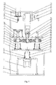
- FIG. 1 is a front view of a wheel cap section chamfering device of the present application.
- FIG. 2 is a left view of the wheel cap section chamfering device of the present application.
- FIG. 3 is a top view of the wheel cap section chamfering device of the present application.
- 1 main frame
- 2 secondary frame
- 3 lower servo motor
- 4 key
- 5 bearing seat
- 6 left bearing seat
- 7 left shaft
- 8 left bearing
- 9 left driven friction wheel
- 10 left sleeve
- 11 left corner cylinder pressure claw
- 12 left turntable
- 13 left mandrel seat
- 14 left mandrel
- 15 chamfer mill
- 16 tool apron
- 17 feeding platform
- 18 feeding cylinder
- 19 guide sleeve
- 20 guide post
- 21 support plate
- 22 guide rail
- 23 compression cylinder
- 24 translation sliding table
- 25 upper servo motor
- 26 driving friction wheel
- 27 right mandrel
- 28 right mandrel seat
- 29 right turntable
- 30 right corner cylinder pressure claw
- 31 right sleeve
- 32 right corner cylinder pressure claw
- a wheel cap section chamfering device comprises a main frame 1 , a secondary frame 2 , a lower servo motor 3 , a key 4 , a bearing seat 5 , a left bearing seat 6 , a left shaft 7 , a left bearing 8 , a left driven friction wheel 9 , a left sleeve 10 , left corner cylinder pressure claws 11 , a left turntable 12 , a left mandrel seat 13 , a left mandrel 14 , a chamfer mill 15 , a tool apron 16 , a feeding platform 17 , a feeding cylinder 18 , guide sleeves 19 , guide posts 20 , a support plate 21 , guide rails 22 , a compression cylinder 23 , a translation sliding table 24 , an upper servo motor 25 , a driving friction wheel 26 , a right mandrel 27 , a right mandrel seat 28 , a right turntable 29 , right corner cylinder pressure claws
- the secondary frame 2 is fixed at the bottom of the main frame 1 , the lower servo motor 3 is mounted on the secondary frame 2 , and the output end of the lower servo motor 3 is connected with the shaft 37 via the key 4 and controls rotation of the shaft 37 under the action of the bearing 38 and the bearing seat 5 .
- the output end of the shaft 37 is fixedly connected with the station rotating platform 36 , and a station I system and a station II system are arranged on the station rotating platform 36 .
- the station I system the left bearing seat 6 is fixed on the left of the station rotating platform 36 , the left shaft 7 and the left bearing 8 are mounted in the left bearing seat 6 , and the left driven friction wheel 9 is mounted on the left shaft 7 and fixed via the left sleeve 10 .
- the output end of the left shaft 7 is fixedly connected with the left turntable 12 , the end face of the left turntable 12 achieves an axial positioning effect, the left mandrel seat 13 is mounted in the center of the left turntable 12 , the left mandrel 14 is mounted on the left mandrel seat 13 to achieve a radial positioning effect, and the three left corner cylinder pressure claws 11 are distributed on the left turntable 12 to clamp a wheel.
- the station II system the right bearing seat 35 is fixed on the right of the station rotating platform 36 , the right shaft 34 and the right bearing 33 are mounted in the right bearing seat 35 , and the right driven friction wheel 32 is mounted on the right shaft 34 and fixed via the right sleeve 31 .
- the output end of the right shaft 34 is fixedly connected with the right turntable 29 , the end face of the right turntable 29 achieves an axial positioning effect, the right mandrel seat 28 is mounted in the center of the right turntable 29 , the right mandrel 27 is mounted on the right mandrel seat 28 to achieve a radial positioning effect, and the three right corner cylinder pressure claws 30 are distributed on the right turntable 29 to clamp the wheel.
- the support plate 21 and the compression cylinder 23 are mounted at the upper part of the main frame 1 , the two guide rails 22 are mounted on the support plate 21 , the translation sliding table 24 is mounted on the guide rails 22 , and the output end of the compression cylinder 23 is connected with the translation sliding table 24 and controls its horizontal motion.
- the upper servo motor 25 is mounted below the translation sliding table 24 , and the driving friction wheel 26 is mounted on the shaft at the output end of the upper servo motor 25 .
- the feeding cylinder 18 and the two guide sleeves 19 are mounted on the main frame 1 above the station I, the output end of the feeding cylinder 18 is connected with the feeding platform 17 , the two guide posts 20 are mounted on the feeding platform 17 , and the feeding cylinder 18 controls the feeding platform 17 to move up and down under the action of the guide posts 20 and the guide sleeves 19 .
- the tool apron 16 is mounted below the feeding platform 17 , the chamfer mill 15 is mounted on the tool apron 16 , angle scales 39 are distributed on the tool apron 16 , and when the angles of chamfers are changed, correspondingly adjusting the mounting angle of the chamfer mill 15 is enough.
- the working process of the device is as follows: firstly, a wheel is put into the station II system, and the right corner cylinder pressure claws 30 clamp the wheel; the lower servo motor 3 is started to drive the station rotating platform 36 to rotate 180°, so that the wheel in the station II system is located directly below the chamfer mill 15 ; then the compression cylinder 23 is started to drive the translation sliding table 24 to move left, so that the driving friction wheel 26 contacts the driven friction wheel and is pre-tightened; the upper servo motor 25 is started, and the wheel rotates at a low speed under the action of drive of the friction wheels; the feeding cylinder 18 is started to drive the chamfer mill 15 to be fed, and the chamfer mill 15 begins removing burrs from the chamfers when arriving at the burr part of the cap section; and finally, chamfering is completed after the wheel continuously rotates one circle.
- the station I system When the wheel in the station II system is in a machined state, the station I system is located outside, the operator puts a wheel to be machined onto the station I system; after the wheel in the station II system is machined, the compression cylinder 23 and the feeding cylinder 18 are reset, drive of the friction wheels is released, the lower servo motor 3 is started to drive the station rotating platform 36 to rotate 180°, the wheel on the station I enters a machining state, at the moment, the just machined wheel on the station II rotates to the outside, the operator takes the machined wheel down and puts a wheel to be machined, and so on.
- the present application may meet the requirement for automatically removing burrs from chamfers at the cap section after wheel machining, reduce the labor intensity of workers, improve the production efficiency and improve the chamfer precision of the cap section; and the device has the characteristics of simple structure, stability, high efficiency, easy operation and the like.
Landscapes
- Engineering & Computer Science (AREA)
- Mechanical Engineering (AREA)
- Milling Processes (AREA)
Applications Claiming Priority (3)
| Application Number | Priority Date | Filing Date | Title |
|---|---|---|---|
| CN201710598333 | 2017-07-21 | ||
| CN2017105983332 | 2017-07-21 | ||
| CN201710598333.2A CN107309416A (zh) | 2017-07-21 | 2017-07-21 | 一种车轮帽口倒角装置 |
Publications (2)
| Publication Number | Publication Date |
|---|---|
| US20190022772A1 US20190022772A1 (en) | 2019-01-24 |
| US10464143B2 true US10464143B2 (en) | 2019-11-05 |
Family
ID=60179238
Family Applications (1)
| Application Number | Title | Priority Date | Filing Date |
|---|---|---|---|
| US15/802,896 Active 2037-12-16 US10464143B2 (en) | 2017-07-21 | 2017-11-03 | Wheel cap section chamfering device |
Country Status (2)
| Country | Link |
|---|---|
| US (1) | US10464143B2 (zh) |
| CN (1) | CN107309416A (zh) |
Families Citing this family (6)
| Publication number | Priority date | Publication date | Assignee | Title |
|---|---|---|---|---|
| CN109663986A (zh) * | 2019-01-28 | 2019-04-23 | 重庆康田齿轮有限公司 | 一种齿圈支座加工设备 |
| CN110238456A (zh) * | 2019-07-24 | 2019-09-17 | 周小玲 | 一种倒角机 |
| CN112247716A (zh) * | 2020-08-27 | 2021-01-22 | 南京涵铭置智能科技有限公司 | 一种端盖去毛刺清洗机以及清洗方法 |
| CN113070770B (zh) * | 2021-04-19 | 2022-06-03 | 陈龙伟 | 用于管件的自动化去毛刺装备 |
| CN117102379A (zh) * | 2023-10-19 | 2023-11-24 | 杭州顿力风机有限公司 | 一种离心风轮的旋压铆紧设备 |
| CN117655406B (zh) * | 2024-02-02 | 2024-04-19 | 杭州安耐特实业有限公司 | 一种刹车片用切割设备 |
Citations (7)
| Publication number | Priority date | Publication date | Assignee | Title |
|---|---|---|---|---|
| US1258089A (en) * | 1914-01-09 | 1918-03-05 | Bullard Machine Tool Company | Automatic machine-tool. |
| US1696027A (en) * | 1928-12-18 | Automatic multiple-spindle lathe | ||
| US1864307A (en) * | 1930-09-25 | 1932-06-21 | Bullard Co | Chip remover and water and dust seal for machine tools |
| US2524170A (en) * | 1947-11-25 | 1950-10-03 | Ernest E Johnson | Lathe tool support |
| US2540186A (en) * | 1944-09-29 | 1951-02-06 | Bullard Co | Machine tool |
| US20010021338A1 (en) * | 2000-03-09 | 2001-09-13 | Toshiba Kikai Kabushiki Kaisha | Machine tool with pivotal spindle head |
| WO2015145345A1 (en) * | 2014-03-27 | 2015-10-01 | M.T. S.R.L. | Swiveling tool-holding module |
Family Cites Families (4)
| Publication number | Priority date | Publication date | Assignee | Title |
|---|---|---|---|---|
| CN103658831B (zh) * | 2013-12-31 | 2016-08-03 | 中信戴卡股份有限公司 | 车轮旋边去除装置 |
| CN105364660A (zh) * | 2015-12-29 | 2016-03-02 | 中信戴卡股份有限公司 | 一种复合式车轮去毛刺装置 |
| CN106271950B (zh) * | 2016-09-24 | 2018-04-10 | 中信戴卡股份有限公司 | 改进的车轮在线去毛刺装置 |
| CN206912230U (zh) * | 2017-07-21 | 2018-01-23 | 中信戴卡股份有限公司 | 一种车轮帽口倒角装置 |
-
2017
- 2017-07-21 CN CN201710598333.2A patent/CN107309416A/zh active Pending
- 2017-11-03 US US15/802,896 patent/US10464143B2/en active Active
Patent Citations (7)
| Publication number | Priority date | Publication date | Assignee | Title |
|---|---|---|---|---|
| US1696027A (en) * | 1928-12-18 | Automatic multiple-spindle lathe | ||
| US1258089A (en) * | 1914-01-09 | 1918-03-05 | Bullard Machine Tool Company | Automatic machine-tool. |
| US1864307A (en) * | 1930-09-25 | 1932-06-21 | Bullard Co | Chip remover and water and dust seal for machine tools |
| US2540186A (en) * | 1944-09-29 | 1951-02-06 | Bullard Co | Machine tool |
| US2524170A (en) * | 1947-11-25 | 1950-10-03 | Ernest E Johnson | Lathe tool support |
| US20010021338A1 (en) * | 2000-03-09 | 2001-09-13 | Toshiba Kikai Kabushiki Kaisha | Machine tool with pivotal spindle head |
| WO2015145345A1 (en) * | 2014-03-27 | 2015-10-01 | M.T. S.R.L. | Swiveling tool-holding module |
Also Published As
| Publication number | Publication date |
|---|---|
| US20190022772A1 (en) | 2019-01-24 |
| CN107309416A (zh) | 2017-11-03 |
Similar Documents
| Publication | Publication Date | Title |
|---|---|---|
| US10464143B2 (en) | Wheel cap section chamfering device | |
| US10399160B2 (en) | Wheel front burr removing device | |
| US20190022815A1 (en) | Automatic wheel front burr removing device | |
| US10737364B2 (en) | Multifunctional wheel burr removing device | |
| CN107283000B (zh) | 一种高精度去车轮帽口毛刺装置 | |
| US10265823B2 (en) | Multi-station wheel burr removing device | |
| US10335868B2 (en) | Pneumatic milling wheel cap section burr device | |
| CN203304703U (zh) | 一种切割装置 | |
| CN105945668A (zh) | 一种可调式车轮去毛刺装置 | |
| CN202824628U (zh) | 一种车轮毛坯去飞边装置 | |
| US10807212B2 (en) | Wheel burr removing device | |
| CN203266375U (zh) | 一种新型的自动外圈滚道和外圆复合超精机 | |
| CN202861454U (zh) | 一种适用于锥形深孔镗削的深孔机床 | |
| CN103878403B (zh) | 一种动力刀台主传动装置 | |
| CN102717121B (zh) | 一种适用于锥形深孔镗削的深孔机床 | |
| CN206912230U (zh) | 一种车轮帽口倒角装置 | |
| CN203804251U (zh) | 一种动力刀座旋转装置 | |
| CN206898401U (zh) | 一种自动去车轮正面毛刺装置 | |
| CN109352554B (zh) | 一种轴承外圈加工用定位调节模具 | |
| CN208438065U (zh) | 一种小内径圆棒刀磨刀机 | |
| CN204383047U (zh) | 一种刻字机装夹装置 | |
| CN103008688A (zh) | 用于机床上车削球面的工装 | |
| CN210756831U (zh) | 一种双面配合调速传动磨床 | |
| CN204526581U (zh) | 一种刻字机通用装夹装置 | |
| CN204353485U (zh) | 主轴头双孔换刀丝杆连接板及主轴套筒前后移动结构 |
Legal Events
| Date | Code | Title | Description |
|---|---|---|---|
| AS | Assignment |
Owner name: CITIC DICASTAL CO., LTD, CHINA Free format text: ASSIGNMENT OF ASSIGNORS INTEREST;ASSIGNORS:LIU, HUIYING;LU, YUEXIN;WU, GUORUI;AND OTHERS;REEL/FRAME:044029/0108 Effective date: 20170914 |
|
| FEPP | Fee payment procedure |
Free format text: ENTITY STATUS SET TO UNDISCOUNTED (ORIGINAL EVENT CODE: BIG.); ENTITY STATUS OF PATENT OWNER: LARGE ENTITY |
|
| STPP | Information on status: patent application and granting procedure in general |
Free format text: NON FINAL ACTION MAILED |
|
| STPP | Information on status: patent application and granting procedure in general |
Free format text: RESPONSE TO NON-FINAL OFFICE ACTION ENTERED AND FORWARDED TO EXAMINER |
|
| STPP | Information on status: patent application and granting procedure in general |
Free format text: NOTICE OF ALLOWANCE MAILED -- APPLICATION RECEIVED IN OFFICE OF PUBLICATIONS |
|
| STPP | Information on status: patent application and granting procedure in general |
Free format text: PUBLICATIONS -- ISSUE FEE PAYMENT VERIFIED |
|
| STCF | Information on status: patent grant |
Free format text: PATENTED CASE |
|
| MAFP | Maintenance fee payment |
Free format text: PAYMENT OF MAINTENANCE FEE, 4TH YEAR, LARGE ENTITY (ORIGINAL EVENT CODE: M1551); ENTITY STATUS OF PATENT OWNER: LARGE ENTITY Year of fee payment: 4 |