US10446764B2 - Organic compound, composition, organic optoelectric device, and display device - Google Patents
Organic compound, composition, organic optoelectric device, and display device Download PDFInfo
- Publication number
- US10446764B2 US10446764B2 US15/307,108 US201515307108A US10446764B2 US 10446764 B2 US10446764 B2 US 10446764B2 US 201515307108 A US201515307108 A US 201515307108A US 10446764 B2 US10446764 B2 US 10446764B2
- Authority
- US
- United States
- Prior art keywords
- substituted
- unsubstituted
- group
- compound
- organic
- Prior art date
- Legal status (The legal status is an assumption and is not a legal conclusion. Google has not performed a legal analysis and makes no representation as to the accuracy of the status listed.)
- Active
Links
- 0 C1=CC=C2C=CC=CC2=C1.CC1=CC=CC(C2=CC=CC(C)=C2)=C1.[1*]C.[2*]C.[3*]C Chemical compound C1=CC=C2C=CC=CC2=C1.CC1=CC=CC(C2=CC=CC(C)=C2)=C1.[1*]C.[2*]C.[3*]C 0.000 description 17
- YBWYFCNIBQZBHW-UHFFFAOYSA-N C1=CC(C2=CC3=C(C=C2)C2=C(C=CC=C2)C2=C3C=CC=C2)=CC(C2=CC=CC(C3=CC(C4=CC(C5=CC=CC6=C5C=CC=C6)=CC=C4)=C4C=CC=CC4=N3)=C2)=C1.C1=CC(C2=CC3=C(C=C2)C2=C(C=CC=C2)C2=C3C=CC=C2)=CC(C2=CC=CC(C3=CC(C4=CC=C(C5=C6C=CC=CC6=CC=C5)C=C4)=C4C=CC=CC4=N3)=C2)=C1.C1=CC=C(C2=CC=CC(C3=C4C=CC=CC4=NC(C4=CC(C5=CC=CC(C6=CC7=C(C=C6)C6=C(C=CC=C6)C6=C7C=CC=C6)=C5)=CC=C4)=C3)=C2)C=C1 Chemical compound C1=CC(C2=CC3=C(C=C2)C2=C(C=CC=C2)C2=C3C=CC=C2)=CC(C2=CC=CC(C3=CC(C4=CC(C5=CC=CC6=C5C=CC=C6)=CC=C4)=C4C=CC=CC4=N3)=C2)=C1.C1=CC(C2=CC3=C(C=C2)C2=C(C=CC=C2)C2=C3C=CC=C2)=CC(C2=CC=CC(C3=CC(C4=CC=C(C5=C6C=CC=CC6=CC=C5)C=C4)=C4C=CC=CC4=N3)=C2)=C1.C1=CC=C(C2=CC=CC(C3=C4C=CC=CC4=NC(C4=CC(C5=CC=CC(C6=CC7=C(C=C6)C6=C(C=CC=C6)C6=C7C=CC=C6)=C5)=CC=C4)=C3)=C2)C=C1 YBWYFCNIBQZBHW-UHFFFAOYSA-N 0.000 description 2
- LHOHDSKDVQQMIO-UHFFFAOYSA-N C1=CC2=C(C=C1)N(C1=CC=NC=C1)C1=C2/C=C(C2=C/C3=C(\C=C/2)N(C2=CC=NC=C2)C2=C3C=CC=C2)\C=C/1.C1=CC2=C(C=C1)N(C1=CN=CN=C1)C1=C2/C=C(C2=C/C3=C(\C=C/2)N(C2=CN=CN=C2)C2=C3C=CC=C2)\C=C/1.C1=CC=C(N2C3=C(C=CC=C3)C3=C2/C=C\C(C2=C\C4=C(/C=C\2)N(C2=CC=CC=C2)C2=C4C=CC=C2)=C/3)C=C1 Chemical compound C1=CC2=C(C=C1)N(C1=CC=NC=C1)C1=C2/C=C(C2=C/C3=C(\C=C/2)N(C2=CC=NC=C2)C2=C3C=CC=C2)\C=C/1.C1=CC2=C(C=C1)N(C1=CN=CN=C1)C1=C2/C=C(C2=C/C3=C(\C=C/2)N(C2=CN=CN=C2)C2=C3C=CC=C2)\C=C/1.C1=CC=C(N2C3=C(C=CC=C3)C3=C2/C=C\C(C2=C\C4=C(/C=C\2)N(C2=CC=CC=C2)C2=C4C=CC=C2)=C/3)C=C1 LHOHDSKDVQQMIO-UHFFFAOYSA-N 0.000 description 2
- CZLIVDYSHDMOFD-UHFFFAOYSA-N C1=CC=C(C2=C3C=CC=CC3=C(C3=C4C=CC=CC4=NC(C4=CC(C5=CC=CC(C6=CC7=C(C=C6)C6=C(C=CC=C6)C6=C7C=CC=C6)=C5)=CC=C4)=C3)C=C2)C=C1.C1=CC=C(C2=CC(C3=CC(C4=CC=CC(C5=CC6=C(C=C5)C5=C(C=CC=C5)C5=C6C=CC=C5)=C4)=CC=C3)=NC3=C2C=CC=C3)C=C1.C1=CC=C(C2=CC=C(C3=C4C=CC=CC4=NC(C4=CC(C5=CC=CC(C6=CC7=C(C=C6)C6=C(C=CC=C6)C6=C7C=CC=C6)=C5)=CC=C4)=C3)C=C2)C=C1 Chemical compound C1=CC=C(C2=C3C=CC=CC3=C(C3=C4C=CC=CC4=NC(C4=CC(C5=CC=CC(C6=CC7=C(C=C6)C6=C(C=CC=C6)C6=C7C=CC=C6)=C5)=CC=C4)=C3)C=C2)C=C1.C1=CC=C(C2=CC(C3=CC(C4=CC=CC(C5=CC6=C(C=C5)C5=C(C=CC=C5)C5=C6C=CC=C5)=C4)=CC=C3)=NC3=C2C=CC=C3)C=C1.C1=CC=C(C2=CC=C(C3=C4C=CC=CC4=NC(C4=CC(C5=CC=CC(C6=CC7=C(C=C6)C6=C(C=CC=C6)C6=C7C=CC=C6)=C5)=CC=C4)=C3)C=C2)C=C1 CZLIVDYSHDMOFD-UHFFFAOYSA-N 0.000 description 2
- QOWXOWRMNWCILA-UHFFFAOYSA-N C1=CC=C(C2=CC(C3=CC=CC=C3)=CC(C3=CC=C(N4C5=CC6=C(C=C5C5=C4C=CC=C5)C4=CC=CC=C4N6C4=CC=CC=C4)C=C3)=C2)C=C1.C1=CC=C(C2=CC(C3=CC=CC=C3)=CC(N3C4=CC5=C(C=C4C4=C3C=CC=C4)C3=CC=CC=C3N5C3=CC=CC=C3)=C2)C=C1.C1=CC=C(C2=CC=C(N3C4=CC5=C(C=C4C4=C3C=CC=C4)C3=CC=CC=C3N5C3=CC=CC=C3)C=C2)C=C1.C1=CC=C(N2C3=CC4=C(C=C3C3=C2C=CC=C3)C2=CC=CC=C2N4C2=CC=CC=C2)C=C1 Chemical compound C1=CC=C(C2=CC(C3=CC=CC=C3)=CC(C3=CC=C(N4C5=CC6=C(C=C5C5=C4C=CC=C5)C4=CC=CC=C4N6C4=CC=CC=C4)C=C3)=C2)C=C1.C1=CC=C(C2=CC(C3=CC=CC=C3)=CC(N3C4=CC5=C(C=C4C4=C3C=CC=C4)C3=CC=CC=C3N5C3=CC=CC=C3)=C2)C=C1.C1=CC=C(C2=CC=C(N3C4=CC5=C(C=C4C4=C3C=CC=C4)C3=CC=CC=C3N5C3=CC=CC=C3)C=C2)C=C1.C1=CC=C(N2C3=CC4=C(C=C3C3=C2C=CC=C3)C2=CC=CC=C2N4C2=CC=CC=C2)C=C1 QOWXOWRMNWCILA-UHFFFAOYSA-N 0.000 description 2
- SAELGKJIUNHQBF-UHFFFAOYSA-N C1=CC=C(C2=CC(C3=CC=CC=C3)=CC(N3C4=C(C=CC=C4)C4=C/C(C5=CC6=C(C=C5)N(C5=CC(C7=CC=CC=C7)=CC(C7=CC=CC=C7)=N5)C5=C6/C=C\C=C/5)=C\C=C\43)=C2)C=C1.C1=CC=C(C2=CC(C3=CC=CC=C3)=CC(N3C4=C(C=CC=C4)C4=C/C(C5=CC6=C(C=C5)N(C5=CC(C7=CC=CC=C7)=NC(C7=CC=CC=C7)=C5)C5=C6/C=C\C=C/5)=C\C=C\43)=C2)C=C1.C1=CC=C(C2=CC(C3=CC=CC=C3)=NC(N3C4=C(C=C(C5=C/C=C6C(=C/5)/C5=C(C=CC=C5)N/6C5=C6C=CC=CC6=CC=C5)C=C4)C4=C3/C=C\C=C/4)=C2)C=C1 Chemical compound C1=CC=C(C2=CC(C3=CC=CC=C3)=CC(N3C4=C(C=CC=C4)C4=C/C(C5=CC6=C(C=C5)N(C5=CC(C7=CC=CC=C7)=CC(C7=CC=CC=C7)=N5)C5=C6/C=C\C=C/5)=C\C=C\43)=C2)C=C1.C1=CC=C(C2=CC(C3=CC=CC=C3)=CC(N3C4=C(C=CC=C4)C4=C/C(C5=CC6=C(C=C5)N(C5=CC(C7=CC=CC=C7)=NC(C7=CC=CC=C7)=C5)C5=C6/C=C\C=C/5)=C\C=C\43)=C2)C=C1.C1=CC=C(C2=CC(C3=CC=CC=C3)=NC(N3C4=C(C=C(C5=C/C=C6C(=C/5)/C5=C(C=CC=C5)N/6C5=C6C=CC=CC6=CC=C5)C=C4)C4=C3/C=C\C=C/4)=C2)C=C1 SAELGKJIUNHQBF-UHFFFAOYSA-N 0.000 description 2
- YHNZPZHUDLAHFJ-UHFFFAOYSA-N C1=CC=C(C2=CC(C3=CC=CC=C3)=CC(N3C4=C(C=CC=C4)C4=C3/C=C\C(C3=CC5=C(C=C3)C3=C(/C=C\C=C/3)N5C3=CC5=C(C=C3)OC3=C5C=CC=C3)=C/4)=C2)C=C1.C1=CC=C(C2=CC=CC(N3C4=C(C=CC=C4)C4=C3/C=C\C(C3=CC5=C(C=C3)C3=C(/C=C\C=C/3)N5C3=CC(C5=CC=NC=C5)=CC(C5=CC=CC=C5)=C3)=C/4)=C2)C=C1.C1=CC=C(C2=CC=CC(N3C4=C(C=CC=C4)C4=C3/C=C\C(C3=CC5=C(C=C3)C3=C(/C=C\C=C/3)N5C3=CC5=C(C=C3)OC3=C5C=CC=C3)=C/4)=C2)C=C1 Chemical compound C1=CC=C(C2=CC(C3=CC=CC=C3)=CC(N3C4=C(C=CC=C4)C4=C3/C=C\C(C3=CC5=C(C=C3)C3=C(/C=C\C=C/3)N5C3=CC5=C(C=C3)OC3=C5C=CC=C3)=C/4)=C2)C=C1.C1=CC=C(C2=CC=CC(N3C4=C(C=CC=C4)C4=C3/C=C\C(C3=CC5=C(C=C3)C3=C(/C=C\C=C/3)N5C3=CC(C5=CC=NC=C5)=CC(C5=CC=CC=C5)=C3)=C/4)=C2)C=C1.C1=CC=C(C2=CC=CC(N3C4=C(C=CC=C4)C4=C3/C=C\C(C3=CC5=C(C=C3)C3=C(/C=C\C=C/3)N5C3=CC5=C(C=C3)OC3=C5C=CC=C3)=C/4)=C2)C=C1 YHNZPZHUDLAHFJ-UHFFFAOYSA-N 0.000 description 2
- QKAVAFMNZPJNIU-UHFFFAOYSA-N C1=CC=C(C2=CC(C3=CC=CC=C3)=CC(N3C4=C(C=CC=C4)C4=C3/C=C\C(C3=CC5=C(C=C3)C3=C(/C=C\C=C/3)N5C3=CC5=C(C=C3)SC3=C5C=CC=C3)=C/4)=C2)C=C1.C1=CC=C(C2=CC=C(N3C4=C(C=CC=C4)C4=C3/C=C\C(C3=CC5=C(C=C3)C3=C(/C=C\C=C/3)N5C3=CC5=C(C=C3)OC3=C5C=CC=C3)=C/4)C=C2)C=C1.C1=CC=C(N2C3=C(C=CC=C3)C3=C2/C=C\C(C2=CC4=C(C=C2)C2=C(/C=C\C=C/2)N4C2=CC4=C(C=C2)OC2=C4C=CC=C2)=C/3)C=C1 Chemical compound C1=CC=C(C2=CC(C3=CC=CC=C3)=CC(N3C4=C(C=CC=C4)C4=C3/C=C\C(C3=CC5=C(C=C3)C3=C(/C=C\C=C/3)N5C3=CC5=C(C=C3)SC3=C5C=CC=C3)=C/4)=C2)C=C1.C1=CC=C(C2=CC=C(N3C4=C(C=CC=C4)C4=C3/C=C\C(C3=CC5=C(C=C3)C3=C(/C=C\C=C/3)N5C3=CC5=C(C=C3)OC3=C5C=CC=C3)=C/4)C=C2)C=C1.C1=CC=C(N2C3=C(C=CC=C3)C3=C2/C=C\C(C2=CC4=C(C=C2)C2=C(/C=C\C=C/2)N4C2=CC4=C(C=C2)OC2=C4C=CC=C2)=C/3)C=C1 QKAVAFMNZPJNIU-UHFFFAOYSA-N 0.000 description 2
- ARZZLOYHXMXYLM-UHFFFAOYSA-N C1=CC=C(C2=CC(C3=CC=CC=C3)=CC(N3C4=C(C=CC=C4)C4=C3C3=C(C=C4)C4=C\C=C/C=C\4N3C3=CC=CC=C3)=C2)C=C1.C1=CC=C(C2=CC(N3C4=CC=CC=C4C4=C3C3=C(C=C4)C4=C(/C=C\C=C/4)N3C3=CC=CC=C3)=CC=C2)C=C1.C1=CC=C(C2=CC=C(N3C4=CC=CC=C4C4=C3C3=C(C=C4)C4=C(/C=C\C=C/4)N3C3=CC=CC=C3)C=C2)C=C1.C1=CC=C(C2=CC=CC(N3C4=C(C=CC=C4)C4=C3C3=C(C=C4)C4=C/C=C/C=C\4N3C3=CC=CC=C3)=N2)C=C1 Chemical compound C1=CC=C(C2=CC(C3=CC=CC=C3)=CC(N3C4=C(C=CC=C4)C4=C3C3=C(C=C4)C4=C\C=C/C=C\4N3C3=CC=CC=C3)=C2)C=C1.C1=CC=C(C2=CC(N3C4=CC=CC=C4C4=C3C3=C(C=C4)C4=C(/C=C\C=C/4)N3C3=CC=CC=C3)=CC=C2)C=C1.C1=CC=C(C2=CC=C(N3C4=CC=CC=C4C4=C3C3=C(C=C4)C4=C(/C=C\C=C/4)N3C3=CC=CC=C3)C=C2)C=C1.C1=CC=C(C2=CC=CC(N3C4=C(C=CC=C4)C4=C3C3=C(C=C4)C4=C/C=C/C=C\4N3C3=CC=CC=C3)=N2)C=C1 ARZZLOYHXMXYLM-UHFFFAOYSA-N 0.000 description 2
- BHYXXMBIDCOQKD-UHFFFAOYSA-N C1=CC=C(C2=CC(C3=CC=CC=C3)=CC(N3C4=C(C=CC=C4)C4=C3C=CC3=C4C4=CC=CC=C4N3C3=CC=CC=C3)=C2)C=C1.C1=CC=C(C2=CC(C3=CC=CC=C3)=NC(N3C4=C(C=CC=C4)C4=C3C=CC3=C4C4=CC=CC=C4N3C3=CC=CC=C3)=C2)C=C1.C1=CC=C(C2=CC(C3=CC=CC=C3)=NC(N3C4=C(C=CC=C4)C4=C3C=CC3=C4C4=CC=CC=C4N3C3=CC=CC=C3)=N2)C=C1 Chemical compound C1=CC=C(C2=CC(C3=CC=CC=C3)=CC(N3C4=C(C=CC=C4)C4=C3C=CC3=C4C4=CC=CC=C4N3C3=CC=CC=C3)=C2)C=C1.C1=CC=C(C2=CC(C3=CC=CC=C3)=NC(N3C4=C(C=CC=C4)C4=C3C=CC3=C4C4=CC=CC=C4N3C3=CC=CC=C3)=C2)C=C1.C1=CC=C(C2=CC(C3=CC=CC=C3)=NC(N3C4=C(C=CC=C4)C4=C3C=CC3=C4C4=CC=CC=C4N3C3=CC=CC=C3)=N2)C=C1 BHYXXMBIDCOQKD-UHFFFAOYSA-N 0.000 description 2
- AKWBUHUKERERJC-UHFFFAOYSA-N C1=CC=C(C2=CC(C3=CC=CC=C3)=CC(N3C4=C(C=CC=C4)C4=C3C=CC3=C4N(C4=CC=CC=C4)/C4=C/C=C/C=C\34)=C2)C=C1.C1=CC=C(C2=CC(C3=CC=CC=C3)=NC(N3C4=C(C=CC=C4)C4=C3C=CC3=C4N(C4=CC=CC=C4)/C4=C/C=C/C=C\34)=N2)C=C1.C1=CC=C(C2=CC(C3=CC=CC=C3)=NC(N3C4=C(C=CC=C4)C4=C3C=CC3=C4N(C4=CC=CC=C4)/C4=C/C=C\C=C\34)=C2)C=C1.C1=CC=C(C2=CC=C(N3C4=CC5=C(C=C4C4=C3C=CC=C4)N(C3=CC=CC=C3)C3=CC=CC=C35)C=C2)C=C1 Chemical compound C1=CC=C(C2=CC(C3=CC=CC=C3)=CC(N3C4=C(C=CC=C4)C4=C3C=CC3=C4N(C4=CC=CC=C4)/C4=C/C=C/C=C\34)=C2)C=C1.C1=CC=C(C2=CC(C3=CC=CC=C3)=NC(N3C4=C(C=CC=C4)C4=C3C=CC3=C4N(C4=CC=CC=C4)/C4=C/C=C/C=C\34)=N2)C=C1.C1=CC=C(C2=CC(C3=CC=CC=C3)=NC(N3C4=C(C=CC=C4)C4=C3C=CC3=C4N(C4=CC=CC=C4)/C4=C/C=C\C=C\34)=C2)C=C1.C1=CC=C(C2=CC=C(N3C4=CC5=C(C=C4C4=C3C=CC=C4)N(C3=CC=CC=C3)C3=CC=CC=C35)C=C2)C=C1 AKWBUHUKERERJC-UHFFFAOYSA-N 0.000 description 2
- VGEJTKMEQBKUSW-UHFFFAOYSA-N C1=CC=C(C2=CC(C3=CC=CC=C3)=CC(N3C4=C(C=CC=C4)C4=C\C(C5=C\C6=C(/C=C\5)N(C5=C\C7=C(\C=C/5)OC5=C7C=CC=C5)C5=C6C=CC=C5)=C/C=C\43)=C2)C=C1.C1=CC=C(C2=CC=C(N3C4=C(C=CC=C4)C4=C\C(C5=C\C6=C(/C=C\5)N(C5=C\C7=C(\C=C/5)OC5=C7C=CC=C5)C5=C6C=CC=C5)=C/C=C\43)C=C2)C=C1.C1=CC=C(N2C3=C(C=CC=C3)C3=C\C(C4=C\C5=C(/C=C\4)N(C4=C\C6=C(\C=C/4)OC4=C6C=CC=C4)C4=C5C=CC=C4)=C/C=C\32)C=C1 Chemical compound C1=CC=C(C2=CC(C3=CC=CC=C3)=CC(N3C4=C(C=CC=C4)C4=C\C(C5=C\C6=C(/C=C\5)N(C5=C\C7=C(\C=C/5)OC5=C7C=CC=C5)C5=C6C=CC=C5)=C/C=C\43)=C2)C=C1.C1=CC=C(C2=CC=C(N3C4=C(C=CC=C4)C4=C\C(C5=C\C6=C(/C=C\5)N(C5=C\C7=C(\C=C/5)OC5=C7C=CC=C5)C5=C6C=CC=C5)=C/C=C\43)C=C2)C=C1.C1=CC=C(N2C3=C(C=CC=C3)C3=C\C(C4=C\C5=C(/C=C\4)N(C4=C\C6=C(\C=C/4)OC4=C6C=CC=C4)C4=C5C=CC=C4)=C/C=C\32)C=C1 VGEJTKMEQBKUSW-UHFFFAOYSA-N 0.000 description 2
- HCSKAWASPNFYJG-UHFFFAOYSA-N C1=CC=C(C2=CC(C3=CC=CC=C3)=CC(N3C4=C(C=CC=C4)C4=C\C(C5=C\C6=C(/C=C\5)N(C5=C\C7=C(\C=C/5)SC5=C7C=CC=C5)C5=C6C=CC=C5)=C/C=C\43)=C2)C=C1.C1=CC=C(C2=CC=C(N3C4=C(C=CC=C4)C4=C\C(C5=C\C6=C(/C=C\5)N(C5=C\C7=C(\C=C/5)SC5=C7C=CC=C5)C5=C6C=CC=C5)=C/C=C\43)C=C2)C=C1.C1=CC=C(N2C3=C(C=CC=C3)C3=C\C(C4=C\C5=C(/C=C\4)N(C4=C\C6=C(\C=C/4)SC4=C6C=CC=C4)C4=C5C=CC=C4)=C/C=C\32)C=C1 Chemical compound C1=CC=C(C2=CC(C3=CC=CC=C3)=CC(N3C4=C(C=CC=C4)C4=C\C(C5=C\C6=C(/C=C\5)N(C5=C\C7=C(\C=C/5)SC5=C7C=CC=C5)C5=C6C=CC=C5)=C/C=C\43)=C2)C=C1.C1=CC=C(C2=CC=C(N3C4=C(C=CC=C4)C4=C\C(C5=C\C6=C(/C=C\5)N(C5=C\C7=C(\C=C/5)SC5=C7C=CC=C5)C5=C6C=CC=C5)=C/C=C\43)C=C2)C=C1.C1=CC=C(N2C3=C(C=CC=C3)C3=C\C(C4=C\C5=C(/C=C\4)N(C4=C\C6=C(\C=C/4)SC4=C6C=CC=C4)C4=C5C=CC=C4)=C/C=C\32)C=C1 HCSKAWASPNFYJG-UHFFFAOYSA-N 0.000 description 2
- LLNCGSCAYIOZEI-UHFFFAOYSA-N C1=CC=C(C2=CC(C3=CC=CC=C3)=CC(N3C4=CC=C(C5=CC6=C(C=C5)N(/C5=C/C=C\C7=C5OC5=C7C=CC=C5)C5=C6C=CC=C5)C=C4C4=C3C=CC=C4)=C2)C=C1.C1=CC=C(C2=CC=C(N3C4=CC=C(C5=CC6=C(C=C5)N(/C5=C/C=C\C7=C5OC5=C7C=CC=C5)C5=C6C=CC=C5)C=C4C4=C3C=CC=C4)C=C2)C=C1.C1=CC=C(N2C3=CC=C(C4=CC5=C(C=C4)N(/C4=C/C=C\C6=C4SC4=C6C=CC=C4)C4=C5C=CC=C4)C=C3C3=C2C=CC=C3)C=C1 Chemical compound C1=CC=C(C2=CC(C3=CC=CC=C3)=CC(N3C4=CC=C(C5=CC6=C(C=C5)N(/C5=C/C=C\C7=C5OC5=C7C=CC=C5)C5=C6C=CC=C5)C=C4C4=C3C=CC=C4)=C2)C=C1.C1=CC=C(C2=CC=C(N3C4=CC=C(C5=CC6=C(C=C5)N(/C5=C/C=C\C7=C5OC5=C7C=CC=C5)C5=C6C=CC=C5)C=C4C4=C3C=CC=C4)C=C2)C=C1.C1=CC=C(N2C3=CC=C(C4=CC5=C(C=C4)N(/C4=C/C=C\C6=C4SC4=C6C=CC=C4)C4=C5C=CC=C4)C=C3C3=C2C=CC=C3)C=C1 LLNCGSCAYIOZEI-UHFFFAOYSA-N 0.000 description 2
- CKADEUBVPDNQCN-UHFFFAOYSA-N C1=CC=C(C2=CC(C3=CC=CC=C3)=CC(N3C4=CC=C(C5=CC6=C(C=C5)N(/C5=C/C=C\C7=C5SC5=C7C=CC=C5)C5=C6C=CC=C5)C=C4C4=C3C=CC=C4)=C2)C=C1.C1=CC=C(C2=CC(N3C4=CC=C(C5=CC6=C(C=C5)N(/C5=C/C=C\C7=C5SC5=C7C=CC=C5)C5=C6C=CC=C5)C=C4C4=C3C=CC=C4)=CC=C2)C=C1.C1=CC=C(C2=CC=C(N3C4=CC=C(C5=CC6=C(C=C5)N(/C5=C/C=C\C7=C5SC5=C7C=CC=C5)C5=C6C=CC=C5)C=C4C4=C3C=CC=C4)C=C2)C=C1 Chemical compound C1=CC=C(C2=CC(C3=CC=CC=C3)=CC(N3C4=CC=C(C5=CC6=C(C=C5)N(/C5=C/C=C\C7=C5SC5=C7C=CC=C5)C5=C6C=CC=C5)C=C4C4=C3C=CC=C4)=C2)C=C1.C1=CC=C(C2=CC(N3C4=CC=C(C5=CC6=C(C=C5)N(/C5=C/C=C\C7=C5SC5=C7C=CC=C5)C5=C6C=CC=C5)C=C4C4=C3C=CC=C4)=CC=C2)C=C1.C1=CC=C(C2=CC=C(N3C4=CC=C(C5=CC6=C(C=C5)N(/C5=C/C=C\C7=C5SC5=C7C=CC=C5)C5=C6C=CC=C5)C=C4C4=C3C=CC=C4)C=C2)C=C1 CKADEUBVPDNQCN-UHFFFAOYSA-N 0.000 description 2
- VODUXIQWKTWBIT-UHFFFAOYSA-N C1=CC=C(C2=CC(C3=CC=CC=C3)=CC(N3C4=CC=CC=C4C4=C3C=C3C(=C4)C4=C(C=CC=C4)N3C3=NC(C4=CC=CC=C4)=NC(C4=CC=CC=C4)=N3)=C2)C=C1.C1=CC=C(C2=CC(C3=CC=CC=C3)=NC(N3C4=CC=CC=C4C4=C3C=C3C(=C4)C4=C(C=CC=C4)N3C3=NC(C4=CC=CC=C4)=NC(C4=CC=CC=C4)=N3)=C2)C=C1.C1=CC=C(C2=CC(C3=CC=CC=C3)=NC(N3C4=CC=CC=C4C4=C3C=C3C(=C4)C4=C(C=CC=C4)N3C3=NC(C4=CC=CC=C4)=NC(C4=CC=CC=C4)=N3)=N2)C=C1.C1=CC=C(C2=NC(C3=CC=CC=C3)=NC(N3C4=CC5=C(C=C4C4=C3C=CC=C4)C3=CC=CC=C3N5C3=NC(C4=CC=CC=C4)=NC(C4=CC=CC=C4)=N3)=N2)C=C1 Chemical compound C1=CC=C(C2=CC(C3=CC=CC=C3)=CC(N3C4=CC=CC=C4C4=C3C=C3C(=C4)C4=C(C=CC=C4)N3C3=NC(C4=CC=CC=C4)=NC(C4=CC=CC=C4)=N3)=C2)C=C1.C1=CC=C(C2=CC(C3=CC=CC=C3)=NC(N3C4=CC=CC=C4C4=C3C=C3C(=C4)C4=C(C=CC=C4)N3C3=NC(C4=CC=CC=C4)=NC(C4=CC=CC=C4)=N3)=C2)C=C1.C1=CC=C(C2=CC(C3=CC=CC=C3)=NC(N3C4=CC=CC=C4C4=C3C=C3C(=C4)C4=C(C=CC=C4)N3C3=NC(C4=CC=CC=C4)=NC(C4=CC=CC=C4)=N3)=N2)C=C1.C1=CC=C(C2=NC(C3=CC=CC=C3)=NC(N3C4=CC5=C(C=C4C4=C3C=CC=C4)C3=CC=CC=C3N5C3=NC(C4=CC=CC=C4)=NC(C4=CC=CC=C4)=N3)=N2)C=C1 VODUXIQWKTWBIT-UHFFFAOYSA-N 0.000 description 2
- QGPBUCUTSMHQAA-UHFFFAOYSA-N C1=CC=C(C2=CC(C3=CC=CC=C3)=NC(N3C4=C(C=C(C5=C/C=C6C(=C/5)/C5=C(C=CC=C5)N/6C5=CC6=C(C=C5)C5=C(C=CC=C5)C5=C6C=CC=C5)C=C4)C4=C3/C=C\C=C/4)=C2)C=C1.C1=CC=C(C2=CC(C3=CC=CC=C3)=NC(N3C4=C(C=C(C5=C/C=C6C(=C/5)/C5=C(C=CC=C5)N/6C5=CC6=C(C=C5)C5=C(C=CC=C5)C5=C6C=CC=C5)C=C4)C4=C3/C=C\C=C/4)=C2)C=C1.C1=CC=C(C2=CC(N3C4=C(C=C(C5=C/C=C6C(=C/5)/C5=C(C=CC=C5)N/6C5=C6C=CC=CC6=CC=C5)C=C4)C4=C3/C=C\C=C/4)=CC(C3=CC=CC=C3)=N2)C=C1 Chemical compound C1=CC=C(C2=CC(C3=CC=CC=C3)=NC(N3C4=C(C=C(C5=C/C=C6C(=C/5)/C5=C(C=CC=C5)N/6C5=CC6=C(C=C5)C5=C(C=CC=C5)C5=C6C=CC=C5)C=C4)C4=C3/C=C\C=C/4)=C2)C=C1.C1=CC=C(C2=CC(C3=CC=CC=C3)=NC(N3C4=C(C=C(C5=C/C=C6C(=C/5)/C5=C(C=CC=C5)N/6C5=CC6=C(C=C5)C5=C(C=CC=C5)C5=C6C=CC=C5)C=C4)C4=C3/C=C\C=C/4)=C2)C=C1.C1=CC=C(C2=CC(N3C4=C(C=C(C5=C/C=C6C(=C/5)/C5=C(C=CC=C5)N/6C5=C6C=CC=CC6=CC=C5)C=C4)C4=C3/C=C\C=C/4)=CC(C3=CC=CC=C3)=N2)C=C1 QGPBUCUTSMHQAA-UHFFFAOYSA-N 0.000 description 2
- TWUUBUILMRJJEN-UHFFFAOYSA-N C1=CC=C(C2=CC(C3=CC=CC=C3)=NC(N3C4=C(C=C(C5=C/C=C6C(=C/5)/C5=C(C=CC=C5)N/6C5=NC(C6=CC=CC=C6)=CC(C6=CC=CC=C6)=C5)C=C4)C4=C3/C=C\C=C/4)=C2)C=C1.C1=CC=C(C2=CC(N3C4=C(C=C(C5=C/C=C6C(=C/5)/C5=C(C=CC=C5)N/6C5=CC(C6=CC=CC=C6)=NC(C6=CC=CC=C6)=C5)C=C4)C4=C3/C=C\C=C/4)=CC(C3=CC=CC=C3)=N2)C=C1.C1=CC=C(C2=CC(N3C4=C(C=CC=C4)C4=C/C(C5=CC6=C(C=C5)N(C5=CC(C7=CC=CC=C7)=NC(C7=CC=CC=C7)=C5)C5=C6/C=C\C=C/5)=C\C=C\43)=NC(C3=CC=CC=C3)=C2)C=C1 Chemical compound C1=CC=C(C2=CC(C3=CC=CC=C3)=NC(N3C4=C(C=C(C5=C/C=C6C(=C/5)/C5=C(C=CC=C5)N/6C5=NC(C6=CC=CC=C6)=CC(C6=CC=CC=C6)=C5)C=C4)C4=C3/C=C\C=C/4)=C2)C=C1.C1=CC=C(C2=CC(N3C4=C(C=C(C5=C/C=C6C(=C/5)/C5=C(C=CC=C5)N/6C5=CC(C6=CC=CC=C6)=NC(C6=CC=CC=C6)=C5)C=C4)C4=C3/C=C\C=C/4)=CC(C3=CC=CC=C3)=N2)C=C1.C1=CC=C(C2=CC(N3C4=C(C=CC=C4)C4=C/C(C5=CC6=C(C=C5)N(C5=CC(C7=CC=CC=C7)=NC(C7=CC=CC=C7)=C5)C5=C6/C=C\C=C/5)=C\C=C\43)=NC(C3=CC=CC=C3)=C2)C=C1 TWUUBUILMRJJEN-UHFFFAOYSA-N 0.000 description 2
- SOSAWUXNNOJCOJ-UHFFFAOYSA-N C1=CC=C(C2=CC(C3=CC=CC=C3)=NC(N3C4=C(C=CC=C4)C4=C3/C=C\C=C/4C3=CC=CC4=C3C3=CC=CC=C3N4C3=CC=CC=C3)=C2)C=C1.C1=CC=C(C2=CC=C(N3C4=C(C=C(C5=C/C=C6C(=C/5)/C5=C(C=CC=C5)N/6C5=CC=C(C6=CC=CC=C6)C=C5)C=C4)C4=C3/C=C\C=C/4)C=C2)C=C1.C1=CC=C(C2=CC=CC(N3C4=CC=C(C5=C/C=C/C6=C\5C5=C(C=CC=C5)N6C5=CC(C6=CC=CC=C6)=CC(C6=CC=CC=C6)=N5)C=C4C4=C3C=CC=C4)=C2)C=C1 Chemical compound C1=CC=C(C2=CC(C3=CC=CC=C3)=NC(N3C4=C(C=CC=C4)C4=C3/C=C\C=C/4C3=CC=CC4=C3C3=CC=CC=C3N4C3=CC=CC=C3)=C2)C=C1.C1=CC=C(C2=CC=C(N3C4=C(C=C(C5=C/C=C6C(=C/5)/C5=C(C=CC=C5)N/6C5=CC=C(C6=CC=CC=C6)C=C5)C=C4)C4=C3/C=C\C=C/4)C=C2)C=C1.C1=CC=C(C2=CC=CC(N3C4=CC=C(C5=C/C=C/C6=C\5C5=C(C=CC=C5)N6C5=CC(C6=CC=CC=C6)=CC(C6=CC=CC=C6)=N5)C=C4C4=C3C=CC=C4)=C2)C=C1 SOSAWUXNNOJCOJ-UHFFFAOYSA-N 0.000 description 2
- ZJZWPUUQVZOHTE-UHFFFAOYSA-N C1=CC=C(C2=CC(C3=CC=CC=C3)=NC(N3C4=C(C=CC=C4)C4=C3C3=C(C=C4)C4=C/C=C/C=C\4N3C3=CC=CC=C3)=N2)C=C1.C1=CC=C(C2=CC(N3C4=C(C=CC=C4)C4=C3C3=C(C=C4)C4=C/C=C/C=C\4N3C3=CC=CC=C3)=NC(C3=CC=CC=C3)=C2)C=C1.C1=CC=C(C2=CC=C(N3C4=CC=CC=C4C4=C3C=C3C(=C4)C4=C(C=CC=C4)N3C3=NC(C4=CC=CC=C4)=NC(C4=CC=CC=C4)=N3)C=N2)C=C1.C1=CC=C(C2=NC(C3=CC=CC=C3)=NC(N3C4=CC=CC=C4C4=C3C3=C(C=C4)C4=C(/C=C\C=C/4)N3C3=CC=CC=C3)=N2)C=C1.C1=CC=C(N2C3=CC=CC=C3C3=C2C2=C(C=C3)C3=C(/C=C\C=C/3)N2C2=CC=CC=C2)C=C1 Chemical compound C1=CC=C(C2=CC(C3=CC=CC=C3)=NC(N3C4=C(C=CC=C4)C4=C3C3=C(C=C4)C4=C/C=C/C=C\4N3C3=CC=CC=C3)=N2)C=C1.C1=CC=C(C2=CC(N3C4=C(C=CC=C4)C4=C3C3=C(C=C4)C4=C/C=C/C=C\4N3C3=CC=CC=C3)=NC(C3=CC=CC=C3)=C2)C=C1.C1=CC=C(C2=CC=C(N3C4=CC=CC=C4C4=C3C=C3C(=C4)C4=C(C=CC=C4)N3C3=NC(C4=CC=CC=C4)=NC(C4=CC=CC=C4)=N3)C=N2)C=C1.C1=CC=C(C2=NC(C3=CC=CC=C3)=NC(N3C4=CC=CC=C4C4=C3C3=C(C=C4)C4=C(/C=C\C=C/4)N3C3=CC=CC=C3)=N2)C=C1.C1=CC=C(N2C3=CC=CC=C3C3=C2C2=C(C=C3)C3=C(/C=C\C=C/3)N2C2=CC=CC=C2)C=C1 ZJZWPUUQVZOHTE-UHFFFAOYSA-N 0.000 description 2
- PQKJSZMDCROPEV-UHFFFAOYSA-N C1=CC=C(C2=CC(C3=CC=CC=C3)=NC(N3C4=CC=C(C5=C/C=C/C6=C\5C5=C(C=CC=C5)N6C5=CC=CC=C5)C=C4C4=C3C=CC=C4)=C2)C=C1.C1=CC=C(C2=CC(C3=CC=CC=C3)=NC(N3C4=CC=CC=C4C4=C3C=C(C3=C/C=C/C5=C\3C3=C(C=CC=C3)N5C3=CC=CC=C3)C=C4)=C2)C=C1.C1=CC=C(C2=CC(N3C4=C(C=CC=C4)C4=C3/C=C/C=C\4C3=CC4=C(C=C3)C3=CC=CC=C3N4C3=CC=CC=C3)=NC(C3=CC=CC=C3)=C2)C=C1 Chemical compound C1=CC=C(C2=CC(C3=CC=CC=C3)=NC(N3C4=CC=C(C5=C/C=C/C6=C\5C5=C(C=CC=C5)N6C5=CC=CC=C5)C=C4C4=C3C=CC=C4)=C2)C=C1.C1=CC=C(C2=CC(C3=CC=CC=C3)=NC(N3C4=CC=CC=C4C4=C3C=C(C3=C/C=C/C5=C\3C3=C(C=CC=C3)N5C3=CC=CC=C3)C=C4)=C2)C=C1.C1=CC=C(C2=CC(N3C4=C(C=CC=C4)C4=C3/C=C/C=C\4C3=CC4=C(C=C3)C3=CC=CC=C3N4C3=CC=CC=C3)=NC(C3=CC=CC=C3)=C2)C=C1 PQKJSZMDCROPEV-UHFFFAOYSA-N 0.000 description 2
- NUISLTZIPZTFEA-UHFFFAOYSA-N C1=CC=C(C2=CC(C3=CC=CC=C3)=NC(N3C4=CC=C(C5=CC6=C(C=C5)N(C5=CC=C7OC8=C(C=CC=C8)C7=C5)C5=C6C=CC=C5)C=C4C4=C3C=CC=C4)=C2)C=C1.CC1(C)C2=CC=C(N3C4=C(C=CC=C4)C4=C3C=CC(C3=CC=C5C(=C3)C3=C(C=CC=C3)N5C3=CC(C5=CC=CC=C5)=CC(C5=CN=CC=C5)=C3)=C4)C=C2C2=C1C=CC=C2.CC1(C)C2=CC=C(N3C4=C(C=CC=C4)C4=C3C=CC(C3=CC=C5C(=C3)C3=C(C=CC=C3)N5C3=CC(C5=CC=CC=C5)=CC(C5=NC=CC=C5)=C3)=C4)C=C2C2=C1C=CC=C2 Chemical compound C1=CC=C(C2=CC(C3=CC=CC=C3)=NC(N3C4=CC=C(C5=CC6=C(C=C5)N(C5=CC=C7OC8=C(C=CC=C8)C7=C5)C5=C6C=CC=C5)C=C4C4=C3C=CC=C4)=C2)C=C1.CC1(C)C2=CC=C(N3C4=C(C=CC=C4)C4=C3C=CC(C3=CC=C5C(=C3)C3=C(C=CC=C3)N5C3=CC(C5=CC=CC=C5)=CC(C5=CN=CC=C5)=C3)=C4)C=C2C2=C1C=CC=C2.CC1(C)C2=CC=C(N3C4=C(C=CC=C4)C4=C3C=CC(C3=CC=C5C(=C3)C3=C(C=CC=C3)N5C3=CC(C5=CC=CC=C5)=CC(C5=NC=CC=C5)=C3)=C4)C=C2C2=C1C=CC=C2 NUISLTZIPZTFEA-UHFFFAOYSA-N 0.000 description 2
- UEBWKCVCOPQQIC-UHFFFAOYSA-N C1=CC=C(C2=CC(C3=CC=CC=C3)=NC(N3C4=CC=C(C5=CC6=C(C=C5)N(C5=CC=C7SC8=C(C=CC=C8)C7=C5)C5=C6C=CC=C5)C=C4C4=C3C=CC=C4)=C2)C=C1.C1=CC=C(C2=CC(C3=CC=CC=N3)=CC(N3C4=CC=C(C5=CC6=C(C=C5)N(C5=CC=C7SC8=C(C=CC=C8)C7=C5)C5=C6C=CC=C5)C=C4C4=C3C=CC=C4)=C2)C=C1.C1=CC=C(C2=CC(C3=CC=NC=C3)=CC(N3C4=CC=C(C5=CC6=C(C=C5)N(C5=CC=C7SC8=C(C=CC=C8)C7=C5)C5=C6C=CC=C5)C=C4C4=C3C=CC=C4)=C2)C=C1 Chemical compound C1=CC=C(C2=CC(C3=CC=CC=C3)=NC(N3C4=CC=C(C5=CC6=C(C=C5)N(C5=CC=C7SC8=C(C=CC=C8)C7=C5)C5=C6C=CC=C5)C=C4C4=C3C=CC=C4)=C2)C=C1.C1=CC=C(C2=CC(C3=CC=CC=N3)=CC(N3C4=CC=C(C5=CC6=C(C=C5)N(C5=CC=C7SC8=C(C=CC=C8)C7=C5)C5=C6C=CC=C5)C=C4C4=C3C=CC=C4)=C2)C=C1.C1=CC=C(C2=CC(C3=CC=NC=C3)=CC(N3C4=CC=C(C5=CC6=C(C=C5)N(C5=CC=C7SC8=C(C=CC=C8)C7=C5)C5=C6C=CC=C5)C=C4C4=C3C=CC=C4)=C2)C=C1 UEBWKCVCOPQQIC-UHFFFAOYSA-N 0.000 description 2
- RWSTWMLKPDHJCX-UHFFFAOYSA-N C1=CC=C(C2=CC(C3=CC=CC=C3)=NC(N3C4=CC=CC=C4C4=C3C(C3=C/C5=C(\C=C/3)N(C3=CC=CC=C3)C3=C5C=CC=C3)=CC=C4)=C2)C=C1.C1=CC=C(C2=CC(N3C4=C(C=CC=C4)C4=C(C5=CC=CC6=C5N(C5=CC=CC=C5)C5=CC=CC=C56)/C=C\C=C\43)=NC(C3=CC=CC=C3)=C2)C=C1.C1=CC=C(C2=CC(N3C4=C(C=CC=C4)C4=C/C=C(C5=CC6=C(C=C5)C5=CC=CC=C5N6C5=CC=CC=C5)/C=C\43)=NC(C3=CC=CC=C3)=C2)C=C1 Chemical compound C1=CC=C(C2=CC(C3=CC=CC=C3)=NC(N3C4=CC=CC=C4C4=C3C(C3=C/C5=C(\C=C/3)N(C3=CC=CC=C3)C3=C5C=CC=C3)=CC=C4)=C2)C=C1.C1=CC=C(C2=CC(N3C4=C(C=CC=C4)C4=C(C5=CC=CC6=C5N(C5=CC=CC=C5)C5=CC=CC=C56)/C=C\C=C\43)=NC(C3=CC=CC=C3)=C2)C=C1.C1=CC=C(C2=CC(N3C4=C(C=CC=C4)C4=C/C=C(C5=CC6=C(C=C5)C5=CC=CC=C5N6C5=CC=CC=C5)/C=C\43)=NC(C3=CC=CC=C3)=C2)C=C1 RWSTWMLKPDHJCX-UHFFFAOYSA-N 0.000 description 2
- ZNTGDXWJKANZKC-UHFFFAOYSA-N C1=CC=C(C2=CC(C3=CC=CC=N3)=CC(N3C4=CC=C(C5=CC6=C(C=C5)N(C5=CC=C7OC8=C(C=CC=C8)C7=C5)C5=C6C=CC=C5)C=C4C4=C3C=CC=C4)=C2)C=C1.C1=CC=C(C2=CC(C3=CC=CN=C3)=CC(N3C4=CC=C(C5=CC6=C(C=C5)N(C5=CC=C7OC8=C(C=CC=C8)C7=C5)C5=C6C=CC=C5)C=C4C4=C3C=CC=C4)=C2)C=C1.C1=CC=C(C2=CC(C3=CC=NC=C3)=CC(N3C4=CC=C(C5=CC6=C(C=C5)N(C5=CC=C7OC8=C(C=CC=C8)C7=C5)C5=C6C=CC=C5)C=C4C4=C3C=CC=C4)=C2)C=C1 Chemical compound C1=CC=C(C2=CC(C3=CC=CC=N3)=CC(N3C4=CC=C(C5=CC6=C(C=C5)N(C5=CC=C7OC8=C(C=CC=C8)C7=C5)C5=C6C=CC=C5)C=C4C4=C3C=CC=C4)=C2)C=C1.C1=CC=C(C2=CC(C3=CC=CN=C3)=CC(N3C4=CC=C(C5=CC6=C(C=C5)N(C5=CC=C7OC8=C(C=CC=C8)C7=C5)C5=C6C=CC=C5)C=C4C4=C3C=CC=C4)=C2)C=C1.C1=CC=C(C2=CC(C3=CC=NC=C3)=CC(N3C4=CC=C(C5=CC6=C(C=C5)N(C5=CC=C7OC8=C(C=CC=C8)C7=C5)C5=C6C=CC=C5)C=C4C4=C3C=CC=C4)=C2)C=C1 ZNTGDXWJKANZKC-UHFFFAOYSA-N 0.000 description 2
- DRKMVTWMNCEQCV-UHFFFAOYSA-N C1=CC=C(C2=CC(C3=CC=CN=C3)=CC(N3C4=CC=C(C5=CC6=C(C=C5)N(C5=CC=C7SC8=C(C=CC=C8)C7=C5)C5=C6C=CC=C5)C=C4C4=C3C=CC=C4)=C2)C=C1.C1=CC=C(C2=CC(N3C4=C(C=CC=C4)C4=C3/C=C\C(C3=CC5=C(C=C3)C3=C(/C=C\C=C/3)N5C3=CC=CC=C3)=C/4)=CC(C3=CC=CC=C3)=N2)C=C1.C1=CC=C(C2=CC(N3C4=C(C=CC=C4)C4=C3/C=C\C(C3=CC5=C(C=C3)C3=C(/C=C\C=C/3)N5C3=CC=CC=C3)=C/4)=CC(C3=CC=NC=C3)=C2)C=C1 Chemical compound C1=CC=C(C2=CC(C3=CC=CN=C3)=CC(N3C4=CC=C(C5=CC6=C(C=C5)N(C5=CC=C7SC8=C(C=CC=C8)C7=C5)C5=C6C=CC=C5)C=C4C4=C3C=CC=C4)=C2)C=C1.C1=CC=C(C2=CC(N3C4=C(C=CC=C4)C4=C3/C=C\C(C3=CC5=C(C=C3)C3=C(/C=C\C=C/3)N5C3=CC=CC=C3)=C/4)=CC(C3=CC=CC=C3)=N2)C=C1.C1=CC=C(C2=CC(N3C4=C(C=CC=C4)C4=C3/C=C\C(C3=CC5=C(C=C3)C3=C(/C=C\C=C/3)N5C3=CC=CC=C3)=C/4)=CC(C3=CC=NC=C3)=C2)C=C1 DRKMVTWMNCEQCV-UHFFFAOYSA-N 0.000 description 2
- NDPGXJNMENARPY-UHFFFAOYSA-N C1=CC=C(C2=CC(N3C4=C(C=CC(C5=C/C6=C(\C=C/5)N(C5=CC(C7=CC=CC=C7)=NC(C7=CC=CC=C7)=C5)C5=C6C=CC=C5)=C4)C4=C3/C=C\C=C/4)=CC=C2)C=C1.C1=CC=C(C2=CC(N3C4=C(C=CC(C5=C/C6=C(\C=C/5)N(C5=NC(C7=CC=CC=C7)=CC(C7=CC=CC=C7)=C5)C5=C6C=CC=C5)=C4)C4=C3/C=C\C=C/4)=CC=C2)C=C1.C1=CC=C(C2=CC=C(N3C4=C(C=CC(C5=C/C6=C(\C=C/5)N(C5=CC(C7=CC=CC=C7)=NC(C7=CC=CC=C7)=C5)C5=C6C=CC=C5)=C4)C4=C3/C=C\C=C/4)C=C2)C=C1 Chemical compound C1=CC=C(C2=CC(N3C4=C(C=CC(C5=C/C6=C(\C=C/5)N(C5=CC(C7=CC=CC=C7)=NC(C7=CC=CC=C7)=C5)C5=C6C=CC=C5)=C4)C4=C3/C=C\C=C/4)=CC=C2)C=C1.C1=CC=C(C2=CC(N3C4=C(C=CC(C5=C/C6=C(\C=C/5)N(C5=NC(C7=CC=CC=C7)=CC(C7=CC=CC=C7)=C5)C5=C6C=CC=C5)=C4)C4=C3/C=C\C=C/4)=CC=C2)C=C1.C1=CC=C(C2=CC=C(N3C4=C(C=CC(C5=C/C6=C(\C=C/5)N(C5=CC(C7=CC=CC=C7)=NC(C7=CC=CC=C7)=C5)C5=C6C=CC=C5)=C4)C4=C3/C=C\C=C/4)C=C2)C=C1 NDPGXJNMENARPY-UHFFFAOYSA-N 0.000 description 2
- ZLXQYISWIAGIDS-UHFFFAOYSA-N C1=CC=C(C2=CC(N3C4=C(C=CC(C5=C/C6=C(\C=C/5)N(C5=CC(C7=CC=NC=C7)=CC(C7=CC=CC=C7)=C5)C5=C6C=CC=C5)=C4)C4=C3/C=C\C=C/4)=CC=C2)C=C1.C1=CC=C(C2=CC(N3C4=C(C=CC(C5=C/C6=C(\C=C/5)N(C5=CC=CC=C5)C5=C6C=CC=C5)=C4)C4=C3/C=C\C=C/4)=CC(C3=CC=CC=C3)=N2)C=C1.C1=CC=C(C2=CC(N3C4=C(C=CC(C5=C/C6=C(\C=C/5)N(C5=CC=CC=C5)C5=C6C=CC=C5)=C4)C4=C3/C=C\C=C/4)=NC(C3=CC=CC=C3)=C2)C=C1 Chemical compound C1=CC=C(C2=CC(N3C4=C(C=CC(C5=C/C6=C(\C=C/5)N(C5=CC(C7=CC=NC=C7)=CC(C7=CC=CC=C7)=C5)C5=C6C=CC=C5)=C4)C4=C3/C=C\C=C/4)=CC=C2)C=C1.C1=CC=C(C2=CC(N3C4=C(C=CC(C5=C/C6=C(\C=C/5)N(C5=CC=CC=C5)C5=C6C=CC=C5)=C4)C4=C3/C=C\C=C/4)=CC(C3=CC=CC=C3)=N2)C=C1.C1=CC=C(C2=CC(N3C4=C(C=CC(C5=C/C6=C(\C=C/5)N(C5=CC=CC=C5)C5=C6C=CC=C5)=C4)C4=C3/C=C\C=C/4)=NC(C3=CC=CC=C3)=C2)C=C1 ZLXQYISWIAGIDS-UHFFFAOYSA-N 0.000 description 2
- SITKWEJINRHSBX-UHFFFAOYSA-N C1=CC=C(C2=CC(N3C4=C(C=CC(C5=C/C6=C(\C=C/5)N(C5=CC=CC=C5)C5=C6C=CC=C5)=C4)C4=C3/C=C\C=C/4)=CC(C3=CC=NC=C3)=C2)C=C1.C1=CC=C(C2=CC=C(N3C4=C(C=CC=C4)C4=C3/C=C\C(C3=CC5=C(C=C3)C3=C(/C=C\C=C/3)N5C3=CC(C5=CC=CC=C5)=NC(C5=CC=CC=C5)=C3)=C/4)C=C2)C=C1.C1=CC=C(C2=CC=C(N3C4=C(C=CC=C4)C4=C3/C=C\C(C3=CC5=C(C=C3)C3=C(/C=C\C=C/3)N5C3=NC(C5=CC=CC=C5)=CC(C5=CC=CC=C5)=C3)=C/4)C=C2)C=C1 Chemical compound C1=CC=C(C2=CC(N3C4=C(C=CC(C5=C/C6=C(\C=C/5)N(C5=CC=CC=C5)C5=C6C=CC=C5)=C4)C4=C3/C=C\C=C/4)=CC(C3=CC=NC=C3)=C2)C=C1.C1=CC=C(C2=CC=C(N3C4=C(C=CC=C4)C4=C3/C=C\C(C3=CC5=C(C=C3)C3=C(/C=C\C=C/3)N5C3=CC(C5=CC=CC=C5)=NC(C5=CC=CC=C5)=C3)=C/4)C=C2)C=C1.C1=CC=C(C2=CC=C(N3C4=C(C=CC=C4)C4=C3/C=C\C(C3=CC5=C(C=C3)C3=C(/C=C\C=C/3)N5C3=NC(C5=CC=CC=C5)=CC(C5=CC=CC=C5)=C3)=C/4)C=C2)C=C1 SITKWEJINRHSBX-UHFFFAOYSA-N 0.000 description 2
- OVEBGQIJZUBJNA-UHFFFAOYSA-N C1=CC=C(C2=CC(N3C4=C(C=CC=C4)C4=C3/C=C(C3=CC=CC5=C3N(C3=CC(C6=CC=CC=C6)=CC(C6=CC=CC=C6)=N3)C3=CC=CC=C35)/C=C\4)=CC=C2)C=C1.C1=CC=C(C2=CC(N3C4=C(C=CC=C4)C4=C\C(C5=CC=CC6=C5N(C5=CC=CC=C5)C5=CC=CC=C56)=C/C=C\43)=NC(C3=CC=CC=C3)=C2)C=C1.C1=CC=C(C2=CC(N3C4=CC=CC=C4C4=C3C(C3=C/C5=C(\C=C/3)C3=C(C=CC=C3)N5C3=CC(C5=CC=CC=C5)=CC(C5=CC=CC=C5)=N3)=CC=C4)=CC=C2)C=C1 Chemical compound C1=CC=C(C2=CC(N3C4=C(C=CC=C4)C4=C3/C=C(C3=CC=CC5=C3N(C3=CC(C6=CC=CC=C6)=CC(C6=CC=CC=C6)=N3)C3=CC=CC=C35)/C=C\4)=CC=C2)C=C1.C1=CC=C(C2=CC(N3C4=C(C=CC=C4)C4=C\C(C5=CC=CC6=C5N(C5=CC=CC=C5)C5=CC=CC=C56)=C/C=C\43)=NC(C3=CC=CC=C3)=C2)C=C1.C1=CC=C(C2=CC(N3C4=CC=CC=C4C4=C3C(C3=C/C5=C(\C=C/3)C3=C(C=CC=C3)N5C3=CC(C5=CC=CC=C5)=CC(C5=CC=CC=C5)=N3)=CC=C4)=CC=C2)C=C1 OVEBGQIJZUBJNA-UHFFFAOYSA-N 0.000 description 2
- YHZCKGFTMJOIRR-UHFFFAOYSA-N C1=CC=C(C2=CC(N3C4=C(C=CC=C4)C4=C3/C=C\C(C3=CC5=C(C=C3)C3=C(/C=C\C=C/3)N5C3=CC=CC=C3)=C/4)=NC(C3=CC=CC=C3)=C2)C=C1.C1=CC=C(C2=CC=C(N3C4=C(C=CC(C5=C/C6=C(\C=C/5)N(C5=CC(C7=CC=NC=C7)=CC(C7=CC=CC=C7)=C5)C5=C6C=CC=C5)=C4)C4=C3/C=C\C=C/4)C=C2)C=C1.C1=CC=C(C2=CC=C(N3C4=C(C=CC(C5=C/C6=C(\C=C/5)N(C5=NC(C7=CC=CC=C7)=CC(C7=CC=CC=C7)=C5)C5=C6C=CC=C5)=C4)C4=C3/C=C\C=C/4)C=C2)C=C1 Chemical compound C1=CC=C(C2=CC(N3C4=C(C=CC=C4)C4=C3/C=C\C(C3=CC5=C(C=C3)C3=C(/C=C\C=C/3)N5C3=CC=CC=C3)=C/4)=NC(C3=CC=CC=C3)=C2)C=C1.C1=CC=C(C2=CC=C(N3C4=C(C=CC(C5=C/C6=C(\C=C/5)N(C5=CC(C7=CC=NC=C7)=CC(C7=CC=CC=C7)=C5)C5=C6C=CC=C5)=C4)C4=C3/C=C\C=C/4)C=C2)C=C1.C1=CC=C(C2=CC=C(N3C4=C(C=CC(C5=C/C6=C(\C=C/5)N(C5=NC(C7=CC=CC=C7)=CC(C7=CC=CC=C7)=C5)C5=C6C=CC=C5)=C4)C4=C3/C=C\C=C/4)C=C2)C=C1 YHZCKGFTMJOIRR-UHFFFAOYSA-N 0.000 description 2
- CIRPMSDFVLFIBQ-UHFFFAOYSA-N C1=CC=C(C2=CC(N3C4=C(C=CC=C4)C4=C3C3=C(C=C4)C4=C/C=C/C=C\4N3C3=CC=CC(C4=CC=CC=C4)=C3)=CC=C2)C=C1.C1=CC=C(C2=CN=C(N3C4=C(C=CC=C4)C4=C3C3=C(C=C4)C4=C\C=C/C=C\4N3C3=CC=CC=C3)N=C2)C=C1.C1=CC=C(C2=NC(C3=CC=CC=C3)=NC(N3C4=C(C=CC=C4)C4=C3C=CC3=C4C4=CC=CC=C4N3C3=CC=CC=C3)=N2)C=C1.C1=CC=C(N2C3=CC=CC=C3C3=C2C=CC2=C3C3=C(C=CC=C3)N2C2=CC=CC=C2)C=C1 Chemical compound C1=CC=C(C2=CC(N3C4=C(C=CC=C4)C4=C3C3=C(C=C4)C4=C/C=C/C=C\4N3C3=CC=CC(C4=CC=CC=C4)=C3)=CC=C2)C=C1.C1=CC=C(C2=CN=C(N3C4=C(C=CC=C4)C4=C3C3=C(C=C4)C4=C\C=C/C=C\4N3C3=CC=CC=C3)N=C2)C=C1.C1=CC=C(C2=NC(C3=CC=CC=C3)=NC(N3C4=C(C=CC=C4)C4=C3C=CC3=C4C4=CC=CC=C4N3C3=CC=CC=C3)=N2)C=C1.C1=CC=C(N2C3=CC=CC=C3C3=C2C=CC2=C3C3=C(C=CC=C3)N2C2=CC=CC=C2)C=C1 CIRPMSDFVLFIBQ-UHFFFAOYSA-N 0.000 description 2
- SNKVFRYJQGNLNW-UHFFFAOYSA-N C1=CC=C(C2=CC(N3C4=C(C=CC=C4)C4=C3C=CC3=C4C4=CC=CC=C4N3C3=CC=CC=C3)=CC=C2)C=C1.C1=CC=C(C2=CC=C(N3C4=C(C=CC=C4)C4=C3C=CC3=C4C4=CC=CC=C4N3C3=CC=CC=C3)C=C2)C=C1.C1=CC=C(C2=CN=C(N3C4=C(C=CC=C4)C4=C3C=CC3=C4C4=CC=CC=C4N3C3=CC=CC=C3)N=C2)C=C1.C1=CC=C(C2=NC(N3C4=C(C=CC=C4)C4=C3C=CC3=C4C4=CC=CC=C4N3C3=CC=CC=C3)=CC=C2)C=C1 Chemical compound C1=CC=C(C2=CC(N3C4=C(C=CC=C4)C4=C3C=CC3=C4C4=CC=CC=C4N3C3=CC=CC=C3)=CC=C2)C=C1.C1=CC=C(C2=CC=C(N3C4=C(C=CC=C4)C4=C3C=CC3=C4C4=CC=CC=C4N3C3=CC=CC=C3)C=C2)C=C1.C1=CC=C(C2=CN=C(N3C4=C(C=CC=C4)C4=C3C=CC3=C4C4=CC=CC=C4N3C3=CC=CC=C3)N=C2)C=C1.C1=CC=C(C2=NC(N3C4=C(C=CC=C4)C4=C3C=CC3=C4C4=CC=CC=C4N3C3=CC=CC=C3)=CC=C2)C=C1 SNKVFRYJQGNLNW-UHFFFAOYSA-N 0.000 description 2
- POGMAGMAIOYTDP-UHFFFAOYSA-N C1=CC=C(C2=CC(N3C4=C(C=CC=C4)C4=C3C=CC3=C4N(C4=CC=CC=C4)/C4=C/C=C/C=C\34)=CC=C2)C=C1.C1=CC=C(C2=CC=C(N3C4=C(C=CC=C4)C4=C3C=CC3=C4N(C4=CC=CC=C4)/C4=C/C=C/C=C\34)C=C2)C=C1.C1=CC=C(C2=CC=CC(N3C4=C(C=CC=C4)C4=C3C=CC3=C4C4=CC=CC=C4N3C3=CC=CC(C4=CC=CC=C4)=C3)=C2)C=C1.C1=CC=C(C2=NC(N3C4=C(C=CC=C4)C4=C3C=CC3=C4N(C4=CC=CC=C4)/C4=C/C=C/C=C\34)=CC=C2)C=C1 Chemical compound C1=CC=C(C2=CC(N3C4=C(C=CC=C4)C4=C3C=CC3=C4N(C4=CC=CC=C4)/C4=C/C=C/C=C\34)=CC=C2)C=C1.C1=CC=C(C2=CC=C(N3C4=C(C=CC=C4)C4=C3C=CC3=C4N(C4=CC=CC=C4)/C4=C/C=C/C=C\34)C=C2)C=C1.C1=CC=C(C2=CC=CC(N3C4=C(C=CC=C4)C4=C3C=CC3=C4C4=CC=CC=C4N3C3=CC=CC(C4=CC=CC=C4)=C3)=C2)C=C1.C1=CC=C(C2=NC(N3C4=C(C=CC=C4)C4=C3C=CC3=C4N(C4=CC=CC=C4)/C4=C/C=C/C=C\34)=CC=C2)C=C1 POGMAGMAIOYTDP-UHFFFAOYSA-N 0.000 description 2
- ICLSLBCYPSEDGK-UHFFFAOYSA-N C1=CC=C(C2=CC(N3C4=CC5=C(C=C4C4=C3C=CC=C4)N(C3=CC=CC(C4=CC=CC=C4)=C3)C3=CC=CC=C35)=CC=C2)C=C1.C1=CC=C(C2=CC(N3C4=CC5=C(C=C4C4=C3C=CC=C4)N(C3=CC=CC=C3)C3=CC=CC=C35)=CC=C2)C=C1.C1=CC=C(C2=CN=C(N3C4=CC5=C(C=C4C4=C3C=CC=C4)N(C3=CC=CC=C3)C3=CC=CC=C35)N=C2)C=C1.C1=CC=C(C2=NC(N3C4=CC5=C(C=C4C4=C3C=CC=C4)N(C3=CC=CC=C3)C3=CC=CC=C35)=CC=C2)C=C1 Chemical compound C1=CC=C(C2=CC(N3C4=CC5=C(C=C4C4=C3C=CC=C4)N(C3=CC=CC(C4=CC=CC=C4)=C3)C3=CC=CC=C35)=CC=C2)C=C1.C1=CC=C(C2=CC(N3C4=CC5=C(C=C4C4=C3C=CC=C4)N(C3=CC=CC=C3)C3=CC=CC=C35)=CC=C2)C=C1.C1=CC=C(C2=CN=C(N3C4=CC5=C(C=C4C4=C3C=CC=C4)N(C3=CC=CC=C3)C3=CC=CC=C35)N=C2)C=C1.C1=CC=C(C2=NC(N3C4=CC5=C(C=C4C4=C3C=CC=C4)N(C3=CC=CC=C3)C3=CC=CC=C35)=CC=C2)C=C1 ICLSLBCYPSEDGK-UHFFFAOYSA-N 0.000 description 2
- IBLDVBQTTJJDCC-UHFFFAOYSA-N C1=CC=C(C2=CC(N3C4=CC=C(C5=CC6=C(C=C5)N(/C5=C/C=C\C7=C5OC5=C7C=CC=C5)C5=C6C=CC=C5)C=C4C4=C3C=CC=C4)=CC=C2)C=C1.C1=CC=C(N2C3=CC=C(C4=CC5=C(C=C4)N(/C4=C/C=C\C6=C4OC4=C6C=CC=C4)C4=C5C=CC=C4)C=C3C3=C2C=CC=C3)C=C1.C1=CC=C(N2C3=CC=C(C4=CC5=C(C=C4)N(C4=C/C=C6C(=C/4)\C4=C(C=CC=C4)N\6C4=CC=CC=C4)C4=C5C=CC=C4)C=C3C3=C2C=CC=C3)C=C1 Chemical compound C1=CC=C(C2=CC(N3C4=CC=C(C5=CC6=C(C=C5)N(/C5=C/C=C\C7=C5OC5=C7C=CC=C5)C5=C6C=CC=C5)C=C4C4=C3C=CC=C4)=CC=C2)C=C1.C1=CC=C(N2C3=CC=C(C4=CC5=C(C=C4)N(/C4=C/C=C\C6=C4OC4=C6C=CC=C4)C4=C5C=CC=C4)C=C3C3=C2C=CC=C3)C=C1.C1=CC=C(N2C3=CC=C(C4=CC5=C(C=C4)N(C4=C/C=C6C(=C/4)\C4=C(C=CC=C4)N\6C4=CC=CC=C4)C4=C5C=CC=C4)C=C3C3=C2C=CC=C3)C=C1 IBLDVBQTTJJDCC-UHFFFAOYSA-N 0.000 description 2
- LMIRZSVCNJVWAB-UHFFFAOYSA-N C1=CC=C(C2=CC(N3C4=CC=C(C5=CC6=C(C=C5)N(C5=CC=C7OC8=C(C=CC=C8)C7=C5)C5=C6C=CC=C5)C=C4C4=C3C=CC=C4)=CC=C2)C=C1.C1=CC=C(C2=CC(N3C4=CC=C(C5=CC6=C(C=C5)N(C5=CC=C7SC8=C(C=CC=C8)C7=C5)C5=C6C=CC=C5)C=C4C4=C3C=CC=C4)=CC=C2)C=C1.CC1(C)C2=CC=C(N3C4=C(C=CC=C4)C4=C3C=CC(C3=CC=C5C(=C3)C3=C(C=CC=C3)N5C3=CC(C5=CC=CC=C5)=CC(C5=CC=CC=C5)=C3)=C4)C=C2C2=C1C=CC=C2 Chemical compound C1=CC=C(C2=CC(N3C4=CC=C(C5=CC6=C(C=C5)N(C5=CC=C7OC8=C(C=CC=C8)C7=C5)C5=C6C=CC=C5)C=C4C4=C3C=CC=C4)=CC=C2)C=C1.C1=CC=C(C2=CC(N3C4=CC=C(C5=CC6=C(C=C5)N(C5=CC=C7SC8=C(C=CC=C8)C7=C5)C5=C6C=CC=C5)C=C4C4=C3C=CC=C4)=CC=C2)C=C1.CC1(C)C2=CC=C(N3C4=C(C=CC=C4)C4=C3C=CC(C3=CC=C5C(=C3)C3=C(C=CC=C3)N5C3=CC(C5=CC=CC=C5)=CC(C5=CC=CC=C5)=C3)=C4)C=C2C2=C1C=CC=C2 LMIRZSVCNJVWAB-UHFFFAOYSA-N 0.000 description 2
- HJIZQQZWWPLDGD-UHFFFAOYSA-N C1=CC=C(C2=CC(N3C4=CC=CC=C4C4=C3C=C3C(=C4)C4=C(C=CC=C4)N3C3=CC(C4=CC=NC=C4)=CC(C4=CC=CC=C4)=C3)=CC=C2)C=C1.C1=CC=C(C2=CC=C(N3C4=CC=CC=C4C4=C3C=C3C(=C4)C4=C(C=CC=C4)N3C3=CC(C4=CC=CC=C4)=CC(C4=CC=CC=C4)=N3)C=C2)C=C1.C1=CC=C(C2=CC=C(N3C4=CC=CC=C4C4=C3C=C3C(=C4)C4=C(C=CC=C4)N3C3=NC(C4=CC=CC=C4)=CC(C4=CC=CC=C4)=N3)C=C2)C=C1.C1=CC=C(C2=CC=C(N3C4=CC=CC=C4C4=C3C=C3C(=C4)C4=C(C=CC=C4)N3C3=NC(C4=CC=CC=C4)=NC(C4=CC=CC=C4)=N3)C=C2)C=C1 Chemical compound C1=CC=C(C2=CC(N3C4=CC=CC=C4C4=C3C=C3C(=C4)C4=C(C=CC=C4)N3C3=CC(C4=CC=NC=C4)=CC(C4=CC=CC=C4)=C3)=CC=C2)C=C1.C1=CC=C(C2=CC=C(N3C4=CC=CC=C4C4=C3C=C3C(=C4)C4=C(C=CC=C4)N3C3=CC(C4=CC=CC=C4)=CC(C4=CC=CC=C4)=N3)C=C2)C=C1.C1=CC=C(C2=CC=C(N3C4=CC=CC=C4C4=C3C=C3C(=C4)C4=C(C=CC=C4)N3C3=NC(C4=CC=CC=C4)=CC(C4=CC=CC=C4)=N3)C=C2)C=C1.C1=CC=C(C2=CC=C(N3C4=CC=CC=C4C4=C3C=C3C(=C4)C4=C(C=CC=C4)N3C3=NC(C4=CC=CC=C4)=NC(C4=CC=CC=C4)=N3)C=C2)C=C1 HJIZQQZWWPLDGD-UHFFFAOYSA-N 0.000 description 2
- GNIDPAZJIPNOEA-UHFFFAOYSA-N C1=CC=C(C2=CC(N3C4=CC=CC=C4C4=C3C=C3C(=C4)C4=C(C=CC=C4)N3C3=CN=C(C4=CC=CC=C4)N=C3)=CC=C2)C=C1.C1=CC=C(C2=NC(C3=CC=CC=C3)=NC(C3=CC=CC(N4C5=CC6=C(C=C5C5=C4C=CC=C5)C4=CC=CC=C4N6C4=CC=CC=C4)=C3)=N2)C=C1.C1=CC=C(N2C3=CC=CC=C3C3=C2C=C2C(=C3)C3=C(C=CC=C3)N2C2=CC(N3C4=C(C=CC=C4)C4=C3C=CC=C4)=CC=C2)C=C1.C1=CC=C(N2C3=CC=CC=C3C3=C2C=C2C(=C3)C3=C(C=CC=C3)N2C2=CC3=C(C=C2)C2=C(C=CC=C2)C2=C3C=CC=C2)C=C1 Chemical compound C1=CC=C(C2=CC(N3C4=CC=CC=C4C4=C3C=C3C(=C4)C4=C(C=CC=C4)N3C3=CN=C(C4=CC=CC=C4)N=C3)=CC=C2)C=C1.C1=CC=C(C2=NC(C3=CC=CC=C3)=NC(C3=CC=CC(N4C5=CC6=C(C=C5C5=C4C=CC=C5)C4=CC=CC=C4N6C4=CC=CC=C4)=C3)=N2)C=C1.C1=CC=C(N2C3=CC=CC=C3C3=C2C=C2C(=C3)C3=C(C=CC=C3)N2C2=CC(N3C4=C(C=CC=C4)C4=C3C=CC=C4)=CC=C2)C=C1.C1=CC=C(N2C3=CC=CC=C3C3=C2C=C2C(=C3)C3=C(C=CC=C3)N2C2=CC3=C(C=C2)C2=C(C=CC=C2)C2=C3C=CC=C2)C=C1 GNIDPAZJIPNOEA-UHFFFAOYSA-N 0.000 description 2
- YPKSCTGZJHWLFY-UHFFFAOYSA-N C1=CC=C(C2=CC=C(N3C4=C(C=CC=C4)C4=C3/C=C\C(C3=CC5=C(C=C3)C3=C(/C=C\C=C/3)N5C3=CC(C5=CC=NC=C5)=CC(C5=CC=CC=C5)=C3)=C/4)C=C2)C=C1.C1=CC=C(C2=CC=CC(N3C4=C(C=CC=C4)C4=C3/C=C\C(C3=CC5=C(C=C3)C3=C(/C=C\C=C/3)N5C3=CC(C5=CC=CC=C5)=NC(C5=CC=CC=C5)=C3)=C/4)=C2)C=C1.C1=CC=C(C2=CC=CC(N3C4=C(C=CC=C4)C4=C3/C=C\C(C3=CC5=C(C=C3)C3=C(/C=C\C=C/3)N5C3=NC(C5=CC=CC=C5)=CC(C5=CC=CC=C5)=C3)=C/4)=C2)C=C1 Chemical compound C1=CC=C(C2=CC=C(N3C4=C(C=CC=C4)C4=C3/C=C\C(C3=CC5=C(C=C3)C3=C(/C=C\C=C/3)N5C3=CC(C5=CC=NC=C5)=CC(C5=CC=CC=C5)=C3)=C/4)C=C2)C=C1.C1=CC=C(C2=CC=CC(N3C4=C(C=CC=C4)C4=C3/C=C\C(C3=CC5=C(C=C3)C3=C(/C=C\C=C/3)N5C3=CC(C5=CC=CC=C5)=NC(C5=CC=CC=C5)=C3)=C/4)=C2)C=C1.C1=CC=C(C2=CC=CC(N3C4=C(C=CC=C4)C4=C3/C=C\C(C3=CC5=C(C=C3)C3=C(/C=C\C=C/3)N5C3=NC(C5=CC=CC=C5)=CC(C5=CC=CC=C5)=C3)=C/4)=C2)C=C1 YPKSCTGZJHWLFY-UHFFFAOYSA-N 0.000 description 2
- BRMKTNMEVUYWPE-UHFFFAOYSA-N C1=CC=C(C2=CC=C(N3C4=C(C=CC=C4)C4=C3/C=C\C(C3=CC5=C(C=C3)C3=C(/C=C\C=C/3)N5C3=CC5=C(C=C3)SC3=C5C=CC=C3)=C/4)C=C2)C=C1.C1=CC=C(C2=CC=CC(N3C4=C(C=CC=C4)C4=C3/C=C\C(C3=CC5=C(C=C3)C3=C(/C=C\C=C/3)N5C3=CC5=C(C=C3)SC3=C5C=CC=C3)=C/4)=C2)C=C1.C1=CC=C(N2C3=C(C=CC=C3)C3=C2/C=C\C(C2=CC4=C(C=C2)C2=C(/C=C\C=C/2)N4C2=CC4=C(C=C2)SC2=C4C=CC=C2)=C/3)C=C1 Chemical compound C1=CC=C(C2=CC=C(N3C4=C(C=CC=C4)C4=C3/C=C\C(C3=CC5=C(C=C3)C3=C(/C=C\C=C/3)N5C3=CC5=C(C=C3)SC3=C5C=CC=C3)=C/4)C=C2)C=C1.C1=CC=C(C2=CC=CC(N3C4=C(C=CC=C4)C4=C3/C=C\C(C3=CC5=C(C=C3)C3=C(/C=C\C=C/3)N5C3=CC5=C(C=C3)SC3=C5C=CC=C3)=C/4)=C2)C=C1.C1=CC=C(N2C3=C(C=CC=C3)C3=C2/C=C\C(C2=CC4=C(C=C2)C2=C(/C=C\C=C/2)N4C2=CC4=C(C=C2)SC2=C4C=CC=C2)=C/3)C=C1 BRMKTNMEVUYWPE-UHFFFAOYSA-N 0.000 description 2
- NIJDHYUYVNIANW-UHFFFAOYSA-N C1=CC=C(C2=CC=C(N3C4=CC5=C(C=C4C4=C3C=CC=C4)C3=CC=CC=C3N5C3=CC=CC(C4=CC=CC=C4)=C3)C=C2)C=C1.C1=CC=C(C2=CC=C(N3C4=CC5=C(C=C4C4=C3C=CC=C4)C3=CC=CC=C3N5C3=CC=NC=C3)C=C2)C=C1.C1=CC=C(C2=CC=CC(N3C4=CC5=C(C=C4C4=C3C=CC=C4)C3=CC=CC=C3N5C3=CC=CC(C4=CC=CC=C4)=C3)=C2)C=C1.C1=CC=C(N2C3=CC=CC=C3C3=C2C=C2C(=C3)C3=C(C=CC=C3)N2C2=CC(C3=CC=C4C(=C3)C3=C(C=CC=C3)C3=C4C=CC=C3)=CC=C2)C=C1 Chemical compound C1=CC=C(C2=CC=C(N3C4=CC5=C(C=C4C4=C3C=CC=C4)C3=CC=CC=C3N5C3=CC=CC(C4=CC=CC=C4)=C3)C=C2)C=C1.C1=CC=C(C2=CC=C(N3C4=CC5=C(C=C4C4=C3C=CC=C4)C3=CC=CC=C3N5C3=CC=NC=C3)C=C2)C=C1.C1=CC=C(C2=CC=CC(N3C4=CC5=C(C=C4C4=C3C=CC=C4)C3=CC=CC=C3N5C3=CC=CC(C4=CC=CC=C4)=C3)=C2)C=C1.C1=CC=C(N2C3=CC=CC=C3C3=C2C=C2C(=C3)C3=C(C=CC=C3)N2C2=CC(C3=CC=C4C(=C3)C3=C(C=CC=C3)C3=C4C=CC=C3)=CC=C2)C=C1 NIJDHYUYVNIANW-UHFFFAOYSA-N 0.000 description 2
- VOGPCWWTAJQRDP-UHFFFAOYSA-N C1=CC=C(C2=CC=C(N3C4=CC5=C(C=C4C4=C3C=CC=C4)C3=CC=CC=C3N5C3=CC=CC=C3)C=N2)C=C1.C1=CC=C(C2=NC(C3=CC=CC=C3)=NC(C3=CC=C(N4C5=CC6=C(C=C5C5=C4C=CC=C5)C4=CC=CC=C4N6C4=CC=CC=C4)C=C3)=N2)C=C1.C1=CC=C(C2=NC(C3=CC=CC=C3)=NC(N3C4=CC5=C(C=C4C4=C3C=CC=C4)C3=CC=CC=C3N5C3=CC=CC=C3)=N2)C=C1.C1=CC=C(N2C3=CC=CC=C3C3=C2C=C2C(=C3)C3=C(C=CC=C3)N2C2=CC=NC=C2)C=C1 Chemical compound C1=CC=C(C2=CC=C(N3C4=CC5=C(C=C4C4=C3C=CC=C4)C3=CC=CC=C3N5C3=CC=CC=C3)C=N2)C=C1.C1=CC=C(C2=NC(C3=CC=CC=C3)=NC(C3=CC=C(N4C5=CC6=C(C=C5C5=C4C=CC=C5)C4=CC=CC=C4N6C4=CC=CC=C4)C=C3)=N2)C=C1.C1=CC=C(C2=NC(C3=CC=CC=C3)=NC(N3C4=CC5=C(C=C4C4=C3C=CC=C4)C3=CC=CC=C3N5C3=CC=CC=C3)=N2)C=C1.C1=CC=C(N2C3=CC=CC=C3C3=C2C=C2C(=C3)C3=C(C=CC=C3)N2C2=CC=NC=C2)C=C1 VOGPCWWTAJQRDP-UHFFFAOYSA-N 0.000 description 2
- QMXKPCASZGNZNE-UHFFFAOYSA-N C1=CC=C(C2=CC=CC(N3C4=C(C=CC=C4)C4=C3C=CC3=C4N(C4=CC=CC(C5=CC=CC=C5)=C4)/C4=C/C=C/C=C\34)=C2)C=C1.C1=CC=C(C2=CN=C(N3C4=C(C=CC=C4)C4=C3C=CC3=C4N(C4=CC=CC=C4)/C4=C/C=C\C=C\34)N=C2)C=C1.C1=CC=C(C2=NC(C3=CC=CC=C3)=NC(N3C4=C(C=CC=C4)C4=C3C=CC3=C4N(C4=CC=CC=C4)/C4=C/C=C/C=C\34)=N2)C=C1.C1=CC=C(N2C3=C(C=CC=C3)C3=C2C=CC2=C3N(C3=CC=CC=C3)/C3=C/C=C/C=C\23)C=C1 Chemical compound C1=CC=C(C2=CC=CC(N3C4=C(C=CC=C4)C4=C3C=CC3=C4N(C4=CC=CC(C5=CC=CC=C5)=C4)/C4=C/C=C/C=C\34)=C2)C=C1.C1=CC=C(C2=CN=C(N3C4=C(C=CC=C4)C4=C3C=CC3=C4N(C4=CC=CC=C4)/C4=C/C=C\C=C\34)N=C2)C=C1.C1=CC=C(C2=NC(C3=CC=CC=C3)=NC(N3C4=C(C=CC=C4)C4=C3C=CC3=C4N(C4=CC=CC=C4)/C4=C/C=C/C=C\34)=N2)C=C1.C1=CC=C(N2C3=C(C=CC=C3)C3=C2C=CC2=C3N(C3=CC=CC=C3)/C3=C/C=C/C=C\23)C=C1 QMXKPCASZGNZNE-UHFFFAOYSA-N 0.000 description 2
- FVGYBZMPDFJMQQ-UHFFFAOYSA-N C1=CC=C(C2=NC(C3=CC=CC=C3)=NC(N3C4=CC5=C(C=C4C4=C3C=CC=C4)C3=CC=CC=C3N5C3=CC=CC4=C3C=CC=C4)=N2)C=C1.C1=CC=C(N2C3=CC=CC=C3C3=C2C=C2C(=C3)C3=C(C=CC=C3)N2C2=C3C=CC=CC3=CC=C2)C=C1.C1=CC=C2C(=C1)C1=C(C=C3C(=C1)C1=C(C=CC=C1)N3C1=CC(C3=CC=C4C(=C3)C3=C(C=CC=C3)C3=C4C=CC=C3)=CC=C1)N2C1=CC=NC=C1.C1=CC=C2C(=C1)C1=C(C=C3C(=C1)C1=C(C=CC=C1)N3C1=CC=NC=C1)N2C1=CC=NC=C1.C1=CC=C2C(=C1)C1=C(C=C3C(=C1)C1=C(C=CC=C1)N3C1=CN=CN=C1)N2C1=CN=CN=C1 Chemical compound C1=CC=C(C2=NC(C3=CC=CC=C3)=NC(N3C4=CC5=C(C=C4C4=C3C=CC=C4)C3=CC=CC=C3N5C3=CC=CC4=C3C=CC=C4)=N2)C=C1.C1=CC=C(N2C3=CC=CC=C3C3=C2C=C2C(=C3)C3=C(C=CC=C3)N2C2=C3C=CC=CC3=CC=C2)C=C1.C1=CC=C2C(=C1)C1=C(C=C3C(=C1)C1=C(C=CC=C1)N3C1=CC(C3=CC=C4C(=C3)C3=C(C=CC=C3)C3=C4C=CC=C3)=CC=C1)N2C1=CC=NC=C1.C1=CC=C2C(=C1)C1=C(C=C3C(=C1)C1=C(C=CC=C1)N3C1=CC=NC=C1)N2C1=CC=NC=C1.C1=CC=C2C(=C1)C1=C(C=C3C(=C1)C1=C(C=CC=C1)N3C1=CN=CN=C1)N2C1=CN=CN=C1 FVGYBZMPDFJMQQ-UHFFFAOYSA-N 0.000 description 2
- CIORAHOLTFBUBJ-UHFFFAOYSA-N C1=CC=C(N2C3=C(C=CC=C3)C3=C2/C=C\C(C2=CC4=C(C=C2)C2=C(C=CC=C2)N4C2=CC=CC(C4=CC5=C(C=C4)C4=CC=CC=C4C4=C5C=CC=C4)=C2)=C/3)C=C1.C1=CC=C2C(=C1)C1=C(C=CC=C1)C1=C2C=CC(C2=CC(N3C4=C(C=CC=C4)C4=C3C=C(C3=C/C5=C(\C=C/3)OC3=C5C=CC=C3)C=C4)=CC=C2)=C1.C1=CC=C2C(=C1)C1=C(C=CC=C1)C1=C2C=CC(C2=CC(N3C4=C(C=CC=C4)C4=C3C=C(C3=C/C5=C(\C=C/3)SC3=C5C=CC=C3)C=C4)=CC=C2)=C1 Chemical compound C1=CC=C(N2C3=C(C=CC=C3)C3=C2/C=C\C(C2=CC4=C(C=C2)C2=C(C=CC=C2)N4C2=CC=CC(C4=CC5=C(C=C4)C4=CC=CC=C4C4=C5C=CC=C4)=C2)=C/3)C=C1.C1=CC=C2C(=C1)C1=C(C=CC=C1)C1=C2C=CC(C2=CC(N3C4=C(C=CC=C4)C4=C3C=C(C3=C/C5=C(\C=C/3)OC3=C5C=CC=C3)C=C4)=CC=C2)=C1.C1=CC=C2C(=C1)C1=C(C=CC=C1)C1=C2C=CC(C2=CC(N3C4=C(C=CC=C4)C4=C3C=C(C3=C/C5=C(\C=C/3)SC3=C5C=CC=C3)C=C4)=CC=C2)=C1 CIORAHOLTFBUBJ-UHFFFAOYSA-N 0.000 description 2
- LRNJZIPXQNLWQU-UHFFFAOYSA-N CC1(C)C2=C(C=CC=C2)C2=C1C=C(N1C3=C(C=CC=C3)C3=C1/C=C\C(C1=C\C=C4C(=C\1)/C1=C(C=CC=C1)N/4C1=CC(C4=CC=CC=C4)=CC(C4=CC=CC=C4)=C1)=C/3)C=C2.CC1(C)C2=C(C=CC=C2)C2=C1C=C(N1C3=C(C=CC=C3)C3=C1/C=C\C(C1=C\C=C4C(=C\1)/C1=C(C=CC=C1)N/4C1=CC=C(C4=CC=CC=C4)C=C1)=C/3)C=C2.CC1(C)C2=C(C=CC=C2)C2=C1C=C(N1C3=C(C=CC=C3)C3=C1/C=C\C(C1=C\C=C4C(=C\1)/C1=C(C=CC=C1)N/4C1=CC=CC=C1)=C/3)C=C2 Chemical compound CC1(C)C2=C(C=CC=C2)C2=C1C=C(N1C3=C(C=CC=C3)C3=C1/C=C\C(C1=C\C=C4C(=C\1)/C1=C(C=CC=C1)N/4C1=CC(C4=CC=CC=C4)=CC(C4=CC=CC=C4)=C1)=C/3)C=C2.CC1(C)C2=C(C=CC=C2)C2=C1C=C(N1C3=C(C=CC=C3)C3=C1/C=C\C(C1=C\C=C4C(=C\1)/C1=C(C=CC=C1)N/4C1=CC=C(C4=CC=CC=C4)C=C1)=C/3)C=C2.CC1(C)C2=C(C=CC=C2)C2=C1C=C(N1C3=C(C=CC=C3)C3=C1/C=C\C(C1=C\C=C4C(=C\1)/C1=C(C=CC=C1)N/4C1=CC=CC=C1)=C/3)C=C2 LRNJZIPXQNLWQU-UHFFFAOYSA-N 0.000 description 2
- FFJAEPRMGPIHIS-UHFFFAOYSA-N CC1(C)C2=CC=C(N3C4=C(C=CC=C4)C4=C3C=CC(C3=CC=C5C(=C3)C3=C(C=CC=C3)N5C3=CC(C5=CC=CC=C5)=CC(C5=CC=CC=C5)=N3)=C4)C=C2C2=C1C=CC=C2.CC1(C)C2=CC=C(N3C4=C(C=CC=C4)C4=C3C=CC(C3=CC=C5C(=C3)C3=C(C=CC=C3)N5C3=CC(C5=CC=CC=C5)=CC(C5=CC=NC=C5)=C3)=C4)C=C2C2=C1C=CC=C2.CC1(C)C2=CC=C(N3C4=C(C=CC=C4)C4=C3C=CC(C3=CC=C5C(=C3)C3=C(C=CC=C3)N5C3=CC(C5=CC=CC=C5)=NC(C5=CC=CC=C5)=C3)=C4)C=C2C2=C1C=CC=C2 Chemical compound CC1(C)C2=CC=C(N3C4=C(C=CC=C4)C4=C3C=CC(C3=CC=C5C(=C3)C3=C(C=CC=C3)N5C3=CC(C5=CC=CC=C5)=CC(C5=CC=CC=C5)=N3)=C4)C=C2C2=C1C=CC=C2.CC1(C)C2=CC=C(N3C4=C(C=CC=C4)C4=C3C=CC(C3=CC=C5C(=C3)C3=C(C=CC=C3)N5C3=CC(C5=CC=CC=C5)=CC(C5=CC=NC=C5)=C3)=C4)C=C2C2=C1C=CC=C2.CC1(C)C2=CC=C(N3C4=C(C=CC=C4)C4=C3C=CC(C3=CC=C5C(=C3)C3=C(C=CC=C3)N5C3=CC(C5=CC=CC=C5)=NC(C5=CC=CC=C5)=C3)=C4)C=C2C2=C1C=CC=C2 FFJAEPRMGPIHIS-UHFFFAOYSA-N 0.000 description 2
- PJRHFWHCLPFGNG-UHFFFAOYSA-N c(cc1)ccc1-c(cc1)ccc1-c1nc(-c2cccc(-c3cc(-c4ccc(c(cccc5)c5c5ccccc55)c5c4)ccc3)c2)c(cccc2)c2n1 Chemical compound c(cc1)ccc1-c(cc1)ccc1-c1nc(-c2cccc(-c3cc(-c4ccc(c(cccc5)c5c5ccccc55)c5c4)ccc3)c2)c(cccc2)c2n1 PJRHFWHCLPFGNG-UHFFFAOYSA-N 0.000 description 2
- JMQSZGZICIUXSR-YOIUIVRPSA-J BCP.BN=P.C1=CC2=C(C=C1)N(C1=CC=C(C3=CC=C(N4C5=C(C=CC=C5)C5=C4/C=C\C=C/5)C=C3)C=C1)C1=C2C=CC=C1.C1=CC=C(N(C2=CC=C(C3=CC=C(N(C4=CC=CC=C4)C4=CC=CC5=C4C=CC=C5)C=C3)C=C2)C2=CC=CC3=C2C=CC=C3)C=C1.CC1=CC(C)=O[Ir]2(O1)C1=C(C=CC=C1)C1=C3C=CC=CC3=CC=N12.CC1=N2C3=C(C=CC=C3C=C1)O[AlH]21(OC2=CC=C(C3=CC=CC=C3)C=C2)OC2=C3C(=CC=C2)C=CC(C)=N31 Chemical compound BCP.BN=P.C1=CC2=C(C=C1)N(C1=CC=C(C3=CC=C(N4C5=C(C=CC=C5)C5=C4/C=C\C=C/5)C=C3)C=C1)C1=C2C=CC=C1.C1=CC=C(N(C2=CC=C(C3=CC=C(N(C4=CC=CC=C4)C4=CC=CC5=C4C=CC=C5)C=C3)C=C2)C2=CC=CC3=C2C=CC=C3)C=C1.CC1=CC(C)=O[Ir]2(O1)C1=C(C=CC=C1)C1=C3C=CC=CC3=CC=N12.CC1=N2C3=C(C=CC=C3C=C1)O[AlH]21(OC2=CC=C(C3=CC=CC=C3)C=C2)OC2=C3C(=CC=C2)C=CC(C)=N31 JMQSZGZICIUXSR-YOIUIVRPSA-J 0.000 description 1
- YMTFYFYALRZPPQ-UHFFFAOYSA-N BrC1=CC(C2=CC=CC(C3=CC=CC=C3)=C2)=CC=C1.BrC1=CC(I)=CC=C1.CC1(C)OB(C2=CC=CC(C3=CC=CC=C3)=C2)OC1(C)C.[I-] Chemical compound BrC1=CC(C2=CC=CC(C3=CC=CC=C3)=C2)=CC=C1.BrC1=CC(I)=CC=C1.CC1(C)OB(C2=CC=CC(C3=CC=CC=C3)=C2)OC1(C)C.[I-] YMTFYFYALRZPPQ-UHFFFAOYSA-N 0.000 description 1
- GFTGGYDZJYTSPE-PBJKEDEQSA-N BrC1=CC(C2=CC=CC(C3=CC=CC=C3)=C2)=CC=C1.CC1(C)OB(B2OC(C)(C)C(C)(C)O2)OC1(C)C.CC1(C)OB(C2=CC(C3=CC=CC(C4=CC=CC=C4)=C3)=CC=C2)OC1(C)C.[2H]CF.[I-].[IH-2] Chemical compound BrC1=CC(C2=CC=CC(C3=CC=CC=C3)=C2)=CC=C1.CC1(C)OB(B2OC(C)(C)C(C)(C)O2)OC1(C)C.CC1(C)OB(C2=CC(C3=CC=CC(C4=CC=CC=C4)=C3)=CC=C2)OC1(C)C.[2H]CF.[I-].[IH-2] GFTGGYDZJYTSPE-PBJKEDEQSA-N 0.000 description 1
- FEUCJSZTYFMVQT-UHFFFAOYSA-N BrC1=CC(C2=CC=CC=C2)=CC(C2=CC=CC=C2)=N1.BrC1=CC2=C(C=C1)CC1=C2/C=C\C=C/1.C.C.C1=CC=C(C2=CC(C3=CC=CC=C3)=NC(N3C4=CC=C(C5=CC6=C(C=C5)N(C5=CC=CC=C5)C5=C6/C=C\C=C/5)C=C4C4=C3C=CC=C4)=C2)C=C1.C1=CC=C(N2C3=C(C=C(C4=CC=C5NC6=C(C=CC=C6)C5=C4)C=C3)C3=C2/C=C\C=C/3)C=C1.CC1(C)OB(C2=CC3=C(C=C2)N(C2=CC=CC=C2)C2=C3/C=C\C=C/2)OC1(C)C.[BH13-10] Chemical compound BrC1=CC(C2=CC=CC=C2)=CC(C2=CC=CC=C2)=N1.BrC1=CC2=C(C=C1)CC1=C2/C=C\C=C/1.C.C.C1=CC=C(C2=CC(C3=CC=CC=C3)=NC(N3C4=CC=C(C5=CC6=C(C=C5)N(C5=CC=CC=C5)C5=C6/C=C\C=C/5)C=C4C4=C3C=CC=C4)=C2)C=C1.C1=CC=C(N2C3=C(C=C(C4=CC=C5NC6=C(C=CC=C6)C5=C4)C=C3)C3=C2/C=C\C=C/3)C=C1.CC1(C)OB(C2=CC3=C(C=C2)N(C2=CC=CC=C2)C2=C3/C=C\C=C/2)OC1(C)C.[BH13-10] FEUCJSZTYFMVQT-UHFFFAOYSA-N 0.000 description 1
- YXLUVRMQRIGWOD-UHFFFAOYSA-N BrC1=CC2=C(C=C1)C1=C(C=CC=C1)C1=C2C=CC=C1.C1=CC=C(N2C3=C(C=CC=C3)C3=C2C=CC(C2=CC4=C(C=C2)C2=C(C=CC=C2)C2=C4C=CC=C2)=C3)C=C1.C1=CC=C(P(C2=CC=CC=C2)C2=CC=CC=C2)C=C1.C1=CC=C(P(C2=CC=CC=C2)C2=CC=CC=C2)C=C1.C1=CC=C(P(C2=CC=CC=C2)C2=CC=CC=C2)C=C1.C1=CC=C(P(C2=CC=CC=C2)C2=CC=CC=C2)C=C1.OB(O)C1=CC2=C(C=C1)N(C1=CC=CC=C1)C1=C2/C=C\C=C/1.[C-10].[Pd] Chemical compound BrC1=CC2=C(C=C1)C1=C(C=CC=C1)C1=C2C=CC=C1.C1=CC=C(N2C3=C(C=CC=C3)C3=C2C=CC(C2=CC4=C(C=C2)C2=C(C=CC=C2)C2=C4C=CC=C2)=C3)C=C1.C1=CC=C(P(C2=CC=CC=C2)C2=CC=CC=C2)C=C1.C1=CC=C(P(C2=CC=CC=C2)C2=CC=CC=C2)C=C1.C1=CC=C(P(C2=CC=CC=C2)C2=CC=CC=C2)C=C1.C1=CC=C(P(C2=CC=CC=C2)C2=CC=CC=C2)C=C1.OB(O)C1=CC2=C(C=C1)N(C1=CC=CC=C1)C1=C2/C=C\C=C/1.[C-10].[Pd] YXLUVRMQRIGWOD-UHFFFAOYSA-N 0.000 description 1
- HNIYRTATILZRSZ-UHFFFAOYSA-N BrC1=CC2=C(C=C1)N(C1=CC3=C(C=C1)C1=C(C=CC=C1)C1=C3C=CC=C1)C1=C2/C=C\C=C/1.C1=CC=C(N2C3=C(C=C(C4=C/C=C5C(=C/4)/C4=C(C=CC=C4)N/5C4=CC5=C(C=C4)C4=C(C=CC=C4)C4=C5C=CC=C4)C=C3)C3=C2/C=C\C=C/3)C=C1.C1=CC=C(P(C2=CC=CC=C2)C2=CC=CC=C2)C=C1.C1=CC=C(P(C2=CC=CC=C2)C2=CC=CC=C2)C=C1.C1=CC=C(P(C2=CC=CC=C2)C2=CC=CC=C2)C=C1.C1=CC=C(P(C2=CC=CC=C2)C2=CC=CC=C2)C=C1.OB(O)C1=CC2=C(C=C1)N(C1=CC=CC=C1)C1=C2/C=C\C=C/1.[BH37-34].[Pd] Chemical compound BrC1=CC2=C(C=C1)N(C1=CC3=C(C=C1)C1=C(C=CC=C1)C1=C3C=CC=C1)C1=C2/C=C\C=C/1.C1=CC=C(N2C3=C(C=C(C4=C/C=C5C(=C/4)/C4=C(C=CC=C4)N/5C4=CC5=C(C=C4)C4=C(C=CC=C4)C4=C5C=CC=C4)C=C3)C3=C2/C=C\C=C/3)C=C1.C1=CC=C(P(C2=CC=CC=C2)C2=CC=CC=C2)C=C1.C1=CC=C(P(C2=CC=CC=C2)C2=CC=CC=C2)C=C1.C1=CC=C(P(C2=CC=CC=C2)C2=CC=CC=C2)C=C1.C1=CC=C(P(C2=CC=CC=C2)C2=CC=CC=C2)C=C1.OB(O)C1=CC2=C(C=C1)N(C1=CC=CC=C1)C1=C2/C=C\C=C/1.[BH37-34].[Pd] HNIYRTATILZRSZ-UHFFFAOYSA-N 0.000 description 1
- ASDCTKBMNHNXCL-UHFFFAOYSA-N BrC1=CC2=C(C=C1)N(C1=CC=C(C3=CC=CC=C3)C=C1)C1=C2/C=C\C=C/1.C1=CC=C(C2=CC=C(N3C4=CC=C(C5=CC6=C(C=C5)N(C5=CC(C7=CC=CC=C7)=CC=C5)C5=C6C=CC=C5)C=C4C4=C3C=CC=C4)C=C2)C=C1.C1=CC=C(P(C2=CC=CC=C2)C2=CC=CC=C2)C=C1.C1=CC=C(P(C2=CC=CC=C2)C2=CC=CC=C2)C=C1.C1=CC=C(P(C2=CC=CC=C2)C2=CC=CC=C2)C=C1.C1=CC=C(P(C2=CC=CC=C2)C2=CC=CC=C2)C=C1.OB(O)C1=CC2=C(C=C1)N(C1=CC(C3=CC=CC=C3)=CC=C1)C1=C2/C=C\C=C/1.[BH46-43].[Pd] Chemical compound BrC1=CC2=C(C=C1)N(C1=CC=C(C3=CC=CC=C3)C=C1)C1=C2/C=C\C=C/1.C1=CC=C(C2=CC=C(N3C4=CC=C(C5=CC6=C(C=C5)N(C5=CC(C7=CC=CC=C7)=CC=C5)C5=C6C=CC=C5)C=C4C4=C3C=CC=C4)C=C2)C=C1.C1=CC=C(P(C2=CC=CC=C2)C2=CC=CC=C2)C=C1.C1=CC=C(P(C2=CC=CC=C2)C2=CC=CC=C2)C=C1.C1=CC=C(P(C2=CC=CC=C2)C2=CC=CC=C2)C=C1.C1=CC=C(P(C2=CC=CC=C2)C2=CC=CC=C2)C=C1.OB(O)C1=CC2=C(C=C1)N(C1=CC(C3=CC=CC=C3)=CC=C1)C1=C2/C=C\C=C/1.[BH46-43].[Pd] ASDCTKBMNHNXCL-UHFFFAOYSA-N 0.000 description 1
- KRLWIDXBSPVFGI-UHFFFAOYSA-N BrC1=CC2=C(C=C1)N(C1=CC=CC=C1)C1=C2/C=C\C=C/1.C1=CC=C(N2C3=C(C=C(C4=C/C=C5C(=C/4)/C4=C(C=CC=C4)N/5C4=CC=CC=C4)C=C3)C3=C2/C=C\C=C/3)C=C1.C1=CC=C(P(C2=CC=CC=C2)C2=CC=CC=C2)C=C1.C1=CC=C(P(C2=CC=CC=C2)C2=CC=CC=C2)C=C1.C1=CC=C(P(C2=CC=CC=C2)C2=CC=CC=C2)C=C1.C1=CC=C(P(C2=CC=CC=C2)C2=CC=CC=C2)C=C1.OB(O)C1=CC2=C(C=C1)N(C1=CC=CC=C1)C1=C2/C=C\C=C/1.[BH34-31].[Pd] Chemical compound BrC1=CC2=C(C=C1)N(C1=CC=CC=C1)C1=C2/C=C\C=C/1.C1=CC=C(N2C3=C(C=C(C4=C/C=C5C(=C/4)/C4=C(C=CC=C4)N/5C4=CC=CC=C4)C=C3)C3=C2/C=C\C=C/3)C=C1.C1=CC=C(P(C2=CC=CC=C2)C2=CC=CC=C2)C=C1.C1=CC=C(P(C2=CC=CC=C2)C2=CC=CC=C2)C=C1.C1=CC=C(P(C2=CC=CC=C2)C2=CC=CC=C2)C=C1.C1=CC=C(P(C2=CC=CC=C2)C2=CC=CC=C2)C=C1.OB(O)C1=CC2=C(C=C1)N(C1=CC=CC=C1)C1=C2/C=C\C=C/1.[BH34-31].[Pd] KRLWIDXBSPVFGI-UHFFFAOYSA-N 0.000 description 1
- GFBWIWJFWMDYII-UHFFFAOYSA-N C.C1=CC=C(C2=CC(C3=CC=CC(C4=CC(C5=CC=CC(C6=NC7=C(C=CC=C7)C(C7=CC=CC=C7)=N6)=C5)=CC=C4)=C3)=CC=C2)C=C1.CC1(C)OB(C2=CC(C3=CC=CC(C4=CC(C5=CC=CC(C6=CC=CC=C6)=C5)=CC=C4)=C3)=CC=C2)OC1(C)C.ClC1=NC(C2=CC=CC=C2)=C2C=CC=CC2=N1.[I-5].[IH-4] Chemical compound C.C1=CC=C(C2=CC(C3=CC=CC(C4=CC(C5=CC=CC(C6=NC7=C(C=CC=C7)C(C7=CC=CC=C7)=N6)=C5)=CC=C4)=C3)=CC=C2)C=C1.CC1(C)OB(C2=CC(C3=CC=CC(C4=CC(C5=CC=CC(C6=CC=CC=C6)=C5)=CC=C4)=C3)=CC=C2)OC1(C)C.ClC1=NC(C2=CC=CC=C2)=C2C=CC=CC2=N1.[I-5].[IH-4] GFBWIWJFWMDYII-UHFFFAOYSA-N 0.000 description 1
- QKSYTDGNAGTSGK-UHFFFAOYSA-N C.C1=CC=C(C2=CC(C3=CC=CC=C3)=CC(C3=CC(C4=CC=CC(C5=NC6=C(C=CC=C6)C(C6=CC=CC=C6)=N5)=C4)=CC=C3)=C2)C=C1.CC1(C)OB(C2=CC(C3=CC=CC(C4=CC(C5=CC=CC=C5)=CC(C5=CC=CC=C5)=C4)=C3)=CC=C2)OC1(C)C.ClC1=NC(C2=CC=CC=C2)=C2C=CC=CC2=N1.[I-5].[I-8] Chemical compound C.C1=CC=C(C2=CC(C3=CC=CC=C3)=CC(C3=CC(C4=CC=CC(C5=NC6=C(C=CC=C6)C(C6=CC=CC=C6)=N5)=C4)=CC=C3)=C2)C=C1.CC1(C)OB(C2=CC(C3=CC=CC(C4=CC(C5=CC=CC=C5)=CC(C5=CC=CC=C5)=C4)=C3)=CC=C2)OC1(C)C.ClC1=NC(C2=CC=CC=C2)=C2C=CC=CC2=N1.[I-5].[I-8] QKSYTDGNAGTSGK-UHFFFAOYSA-N 0.000 description 1
- NVVAWQZIXBPLKM-UHFFFAOYSA-N C.C1=CC=C(C2=CC=C(C3=NC(C4=CC(C5=CC=CC(C6=CC(C7=CC=CC(C8=CC=CC=C8)=C7)=CC=C6)=C5)=CC=C4)=NC4=C3C=CC=C4)C=C2)C=C1.CC1(C)OB(C2=CC(C3=CC=CC(C4=CC(C5=CC=CC(C6=CC=CC=C6)=C5)=CC=C4)=C3)=CC=C2)OC1(C)C.ClC1=NC(C2=CC=C(C3=CC=CC=C3)C=C2)=C2C=CC=CC2=N1.[I-6].[IH-4] Chemical compound C.C1=CC=C(C2=CC=C(C3=NC(C4=CC(C5=CC=CC(C6=CC(C7=CC=CC(C8=CC=CC=C8)=C7)=CC=C6)=C5)=CC=C4)=NC4=C3C=CC=C4)C=C2)C=C1.CC1(C)OB(C2=CC(C3=CC=CC(C4=CC(C5=CC=CC(C6=CC=CC=C6)=C5)=CC=C4)=C3)=CC=C2)OC1(C)C.ClC1=NC(C2=CC=C(C3=CC=CC=C3)C=C2)=C2C=CC=CC2=N1.[I-6].[IH-4] NVVAWQZIXBPLKM-UHFFFAOYSA-N 0.000 description 1
- SMWKGOMLONNBGV-UHFFFAOYSA-N C.C1=CC=C(C2=CC=C(C3=NC(C4=CC(C5=CC=CC(C6=CC(C7=CC=CC=C7)=CC(C7=CC=CC=C7)=C6)=C5)=CC=C4)=C4C=CC=CC4=N3)C=C2)C=C1.CC1(C)OB(C2=CC(C3=CC=CC(C4=CC(C5=CC=CC=C5)=CC(C5=CC=CC=C5)=C4)=C3)=CC=C2)OC1(C)C.ClC1=NC(C2=CC=C(C3=CC=CC=C3)C=C2)=NC2=C1C=CC=C2.[I-8] Chemical compound C.C1=CC=C(C2=CC=C(C3=NC(C4=CC(C5=CC=CC(C6=CC(C7=CC=CC=C7)=CC(C7=CC=CC=C7)=C6)=C5)=CC=C4)=C4C=CC=CC4=N3)C=C2)C=C1.CC1(C)OB(C2=CC(C3=CC=CC(C4=CC(C5=CC=CC=C5)=CC(C5=CC=CC=C5)=C4)=C3)=CC=C2)OC1(C)C.ClC1=NC(C2=CC=C(C3=CC=CC=C3)C=C2)=NC2=C1C=CC=C2.[I-8] SMWKGOMLONNBGV-UHFFFAOYSA-N 0.000 description 1
- GFRQAZLSZGMRJR-UHFFFAOYSA-N C.C1=CC=C(C2=CC=C(C3=NC(C4=CC(C5=CC=CC(C6=CC(C7=CC=CC=C7)=CC(C7=CC=CC=C7)=C6)=C5)=CC=C4)=NC4=C3C=CC=C4)C=C2)C=C1.CC1(C)OB(C2=CC(C3=CC=CC(C4=CC(C5=CC=CC=C5)=CC(C5=CC=CC=C5)=C4)=C3)=CC=C2)OC1(C)C.ClC1=NC(C2=CC=C(C3=CC=CC=C3)C=C2)=C2C=CC=CC2=N1.[I-6].[I-8] Chemical compound C.C1=CC=C(C2=CC=C(C3=NC(C4=CC(C5=CC=CC(C6=CC(C7=CC=CC=C7)=CC(C7=CC=CC=C7)=C6)=C5)=CC=C4)=NC4=C3C=CC=C4)C=C2)C=C1.CC1(C)OB(C2=CC(C3=CC=CC(C4=CC(C5=CC=CC=C5)=CC(C5=CC=CC=C5)=C4)=C3)=CC=C2)OC1(C)C.ClC1=NC(C2=CC=C(C3=CC=CC=C3)C=C2)=C2C=CC=CC2=N1.[I-6].[I-8] GFRQAZLSZGMRJR-UHFFFAOYSA-N 0.000 description 1
- IQKGMBJGPXZXFT-UHFFFAOYSA-N C.C1=CC=C(C2=CC=C(C3=NC(C4=CC(C5=CC=CC(C6=CC7=C(C=C6)C6=C(C=CC=C6)C6=C7C=CC=C6)=C5)=CC=C4)=C4C=CC=CC4=N3)C=C2)C=C1.CC1(C)OB(C2=CC=CC(C3=CC(C4=CC5=C(C=C4)C4=C(C=CC=C4)C4=CC=CC=C45)=CC=C3)=C2)OC1(C)C.ClC1=NC(C2=CC=C(C3=CC=CC=C3)C=C2)=NC2=C1C=CC=C2.[I-10] Chemical compound C.C1=CC=C(C2=CC=C(C3=NC(C4=CC(C5=CC=CC(C6=CC7=C(C=C6)C6=C(C=CC=C6)C6=C7C=CC=C6)=C5)=CC=C4)=C4C=CC=CC4=N3)C=C2)C=C1.CC1(C)OB(C2=CC=CC(C3=CC(C4=CC5=C(C=C4)C4=C(C=CC=C4)C4=CC=CC=C45)=CC=C3)=C2)OC1(C)C.ClC1=NC(C2=CC=C(C3=CC=CC=C3)C=C2)=NC2=C1C=CC=C2.[I-10] IQKGMBJGPXZXFT-UHFFFAOYSA-N 0.000 description 1
- RFTMGMATRXWEDX-UHFFFAOYSA-N C.C1=CC=C(C2=CC=C(C3=NC(C4=CC(C5=CC=CC(C6=CC7=C(C=C6)C6=C(C=CC=C6)C6=C7C=CC=C6)=C5)=CC=C4)=NC4=C3C=CC=C4)C=C2)C=C1.CC1(C)OB(C2=CC=CC(C3=CC(C4=CC5=C(C=C4)C4=C(C=CC=C4)C4=CC=CC=C45)=CC=C3)=C2)OC1(C)C.ClC1=NC(C2=CC=C(C3=CC=CC=C3)C=C2)=C2C=CC=CC2=N1.[I-10].[I-6] Chemical compound C.C1=CC=C(C2=CC=C(C3=NC(C4=CC(C5=CC=CC(C6=CC7=C(C=C6)C6=C(C=CC=C6)C6=C7C=CC=C6)=C5)=CC=C4)=NC4=C3C=CC=C4)C=C2)C=C1.CC1(C)OB(C2=CC=CC(C3=CC(C4=CC5=C(C=C4)C4=C(C=CC=C4)C4=CC=CC=C45)=CC=C3)=C2)OC1(C)C.ClC1=NC(C2=CC=C(C3=CC=CC=C3)C=C2)=C2C=CC=CC2=N1.[I-10].[I-6] RFTMGMATRXWEDX-UHFFFAOYSA-N 0.000 description 1
- UXJKZDFBUAHSCN-JYUHCRIGSA-N C.CC1(C)OB(B2OC(C)(C)C(C)(C)O2)OC1(C)C.CC1(C)OB(C2=CC(C3=CC(C4=CC=C(C5=CC=CC=C5)C=C4)=CC=C3)=CC=C2)OC1(C)C.[2H]CF.[I-11].[I-12] Chemical compound C.CC1(C)OB(B2OC(C)(C)C(C)(C)O2)OC1(C)C.CC1(C)OB(C2=CC(C3=CC(C4=CC=C(C5=CC=CC=C5)C=C4)=CC=C3)=CC=C2)OC1(C)C.[2H]CF.[I-11].[I-12] UXJKZDFBUAHSCN-JYUHCRIGSA-N 0.000 description 1
- VQLOJAZGLNSUFH-UHFFFAOYSA-N C1=CC(C2=CC3=C(C=C2)C2=C(C=CC=C2)C2=C3C=CC=C2)=CC(C2=CC=CC(C3=C4C=CC=CC4=NC(C4=CC=C(/C5=C/C=C\C6=C5C=CC=C6)C=C4)=N3)=C2)=C1.C1=CC=C(C2=CC(C3=CC=CC=C3)=CC(C3=NC(C4=CC(C5=CC=CC(C6=CC7=C(C=C6)C6=C(C=CC=C6)C6=C7C=CC=C6)=C5)=CC=C4)=C4C=CC=CC4=N3)=C2)C=C1.C1=CC=C(C2=CC(C3=NC(C4=CC(C5=CC=CC(C6=CC7=C(C=C6)C6=C(C=CC=C6)C6=C7C=CC=C6)=C5)=CC=C4)=C4C=CC=CC4=N3)=CC=C2)C=C1.C1=CC=C(C2=CC=C(C3=NC(C4=CC(C5=CC=CC(C6=CC7=C(C=C6)C6=C(C=CC=C6)C6=C7C=CC=C6)=C5)=CC=C4)=C4C=CC=CC4=N3)C=C2)C=C1.C1=CC=C(C2=NC(C3=CC=CC=C3)=NC(C3=NC(C4=CC(C5=CC=CC(C6=CC7=C(C=C6)C6=C(C=CC=C6)C6=C7C=CC=C6)=C5)=CC=C4)=C4C=CC=CC4=N3)=N2)C=C1 Chemical compound C1=CC(C2=CC3=C(C=C2)C2=C(C=CC=C2)C2=C3C=CC=C2)=CC(C2=CC=CC(C3=C4C=CC=CC4=NC(C4=CC=C(/C5=C/C=C\C6=C5C=CC=C6)C=C4)=N3)=C2)=C1.C1=CC=C(C2=CC(C3=CC=CC=C3)=CC(C3=NC(C4=CC(C5=CC=CC(C6=CC7=C(C=C6)C6=C(C=CC=C6)C6=C7C=CC=C6)=C5)=CC=C4)=C4C=CC=CC4=N3)=C2)C=C1.C1=CC=C(C2=CC(C3=NC(C4=CC(C5=CC=CC(C6=CC7=C(C=C6)C6=C(C=CC=C6)C6=C7C=CC=C6)=C5)=CC=C4)=C4C=CC=CC4=N3)=CC=C2)C=C1.C1=CC=C(C2=CC=C(C3=NC(C4=CC(C5=CC=CC(C6=CC7=C(C=C6)C6=C(C=CC=C6)C6=C7C=CC=C6)=C5)=CC=C4)=C4C=CC=CC4=N3)C=C2)C=C1.C1=CC=C(C2=NC(C3=CC=CC=C3)=NC(C3=NC(C4=CC(C5=CC=CC(C6=CC7=C(C=C6)C6=C(C=CC=C6)C6=C7C=CC=C6)=C5)=CC=C4)=C4C=CC=CC4=N3)=N2)C=C1 VQLOJAZGLNSUFH-UHFFFAOYSA-N 0.000 description 1
- BVOMMORJWVBDPO-UHFFFAOYSA-N C1=CC(C2=CC3=C(C=C2)C2=C(C=CC=C2)C2=C3C=CC=C2)=CC(C2=CC=CC(C3=C4C=CC=CC4=NC(C4=CC=C(C5=CC=CC6=C5C=CC=C6)C=C4)=N3)=C2)=C1.C1=CC=C(C2=CC(C3=CC=CC=C3)=CC(C3=NC(C4=CC(C5=CC=CC(C6=CC7=C(C=C6)C6=C(C=CC=C6)C6=C7C=CC=C6)=C5)=CC=C4)=C4C=CC=CC4=N3)=C2)C=C1.C1=CC=C(C2=CC(C3=NC(C4=CC(C5=CC=CC(C6=CC7=C(C=C6)C6=C(C=CC=C6)C6=C7C=CC=C6)=C5)=CC=C4)=C4C=CC=CC4=N3)=CC=C2)C=C1.C1=CC=C(C2=CC=C(C3=NC(C4=CC(C5=CC=CC(C6=CC7=C(C=C6)C6=C(C=CC=C6)C6=C7C=CC=C6)=C5)=CC=C4)=C4C=CC=CC4=N3)C=C2)C=C1.C1=CC=C(C2=NC3=C(C=CC=C3)C(C3=CC(C4=CC=CC(C5=CC6=C(C=C5)C5=C(C=CC=C5)C5=C6C=CC=C5)=C4)=CC=C3)=N2)C=C1 Chemical compound C1=CC(C2=CC3=C(C=C2)C2=C(C=CC=C2)C2=C3C=CC=C2)=CC(C2=CC=CC(C3=C4C=CC=CC4=NC(C4=CC=C(C5=CC=CC6=C5C=CC=C6)C=C4)=N3)=C2)=C1.C1=CC=C(C2=CC(C3=CC=CC=C3)=CC(C3=NC(C4=CC(C5=CC=CC(C6=CC7=C(C=C6)C6=C(C=CC=C6)C6=C7C=CC=C6)=C5)=CC=C4)=C4C=CC=CC4=N3)=C2)C=C1.C1=CC=C(C2=CC(C3=NC(C4=CC(C5=CC=CC(C6=CC7=C(C=C6)C6=C(C=CC=C6)C6=C7C=CC=C6)=C5)=CC=C4)=C4C=CC=CC4=N3)=CC=C2)C=C1.C1=CC=C(C2=CC=C(C3=NC(C4=CC(C5=CC=CC(C6=CC7=C(C=C6)C6=C(C=CC=C6)C6=C7C=CC=C6)=C5)=CC=C4)=C4C=CC=CC4=N3)C=C2)C=C1.C1=CC=C(C2=NC3=C(C=CC=C3)C(C3=CC(C4=CC=CC(C5=CC6=C(C=C5)C5=C(C=CC=C5)C5=C6C=CC=C5)=C4)=CC=C3)=N2)C=C1 BVOMMORJWVBDPO-UHFFFAOYSA-N 0.000 description 1
- FCVMMYYZVSLNCW-UHFFFAOYSA-N C1=CC(C2=CC3=C(C=C2)C2=C(C=CC=C2)C2=C3C=CC=C2)=CC(C2=CC=CC(C3=CC(C4=CC(C5=CC=NC=C5)=CC=N4)=C4C=CC=CC4=N3)=C2)=C1.C1=CC=C(C2=CC=C(C3=C4C=CC=CC4=NC(C4=CC(C5=CC=CC(C6=CC7=C(C=C6)C6=C(C=CC=C6)C6=C7C=CC=C6)=C5)=CC=C4)=C3)C=N2)C=C1.C1=CC=C(C2=CC=NC(C3=C4C=CC=CC4=NC(C4=CC(C5=CC=CC(C6=CC7=C(C=C6)C6=C(C=CC=C6)C6=C7C=CC=C6)=C5)=CC=C4)=C3)=C2)C=C1.C1=CC=C(C2=CN=C(C3=C4C=CC=CC4=NC(C4=CC(C5=CC=CC(C6=CC7=C(C=C6)C6=C(C=CC=C6)C6=C7C=CC=C6)=C5)=CC=C4)=C3)C=C2)C=C1 Chemical compound C1=CC(C2=CC3=C(C=C2)C2=C(C=CC=C2)C2=C3C=CC=C2)=CC(C2=CC=CC(C3=CC(C4=CC(C5=CC=NC=C5)=CC=N4)=C4C=CC=CC4=N3)=C2)=C1.C1=CC=C(C2=CC=C(C3=C4C=CC=CC4=NC(C4=CC(C5=CC=CC(C6=CC7=C(C=C6)C6=C(C=CC=C6)C6=C7C=CC=C6)=C5)=CC=C4)=C3)C=N2)C=C1.C1=CC=C(C2=CC=NC(C3=C4C=CC=CC4=NC(C4=CC(C5=CC=CC(C6=CC7=C(C=C6)C6=C(C=CC=C6)C6=C7C=CC=C6)=C5)=CC=C4)=C3)=C2)C=C1.C1=CC=C(C2=CN=C(C3=C4C=CC=CC4=NC(C4=CC(C5=CC=CC(C6=CC7=C(C=C6)C6=C(C=CC=C6)C6=C7C=CC=C6)=C5)=CC=C4)=C3)C=C2)C=C1 FCVMMYYZVSLNCW-UHFFFAOYSA-N 0.000 description 1
- YJOPWUIDBJRLJY-UHFFFAOYSA-N C1=CC(C2=CC3=C(C=C2)C2=C(C=CC=C2)C2=C3C=CC=C2)=CC(C2=CC=CC(C3=CC(C4=CC(C5=CC=NC=C5)=CC=N4)=C4C=CC=CC4=N3)=C2)=C1.C1=CC=C(C2=CC=NC(C3=C4C=CC=CC4=NC(C4=CC(C5=CC=CC(C6=CC7=C(C=C6)C6=C(C=CC=C6)C6=C7C=CC=C6)=C5)=CC=C4)=C3)=C2)C=C1.C1=CC=C(C2=CN=C(C3=C4C=CC=CC4=NC(C4=CC(C5=CC=CC(C6=CC7=C(C=C6)C6=C(C=CC=C6)C6=C7C=CC=C6)=C5)=CC=C4)=C3)C=C2)C=C1 Chemical compound C1=CC(C2=CC3=C(C=C2)C2=C(C=CC=C2)C2=C3C=CC=C2)=CC(C2=CC=CC(C3=CC(C4=CC(C5=CC=NC=C5)=CC=N4)=C4C=CC=CC4=N3)=C2)=C1.C1=CC=C(C2=CC=NC(C3=C4C=CC=CC4=NC(C4=CC(C5=CC=CC(C6=CC7=C(C=C6)C6=C(C=CC=C6)C6=C7C=CC=C6)=C5)=CC=C4)=C3)=C2)C=C1.C1=CC=C(C2=CN=C(C3=C4C=CC=CC4=NC(C4=CC(C5=CC=CC(C6=CC7=C(C=C6)C6=C(C=CC=C6)C6=C7C=CC=C6)=C5)=CC=C4)=C3)C=C2)C=C1 YJOPWUIDBJRLJY-UHFFFAOYSA-N 0.000 description 1
- IOFSOCIUQGGDJY-UHFFFAOYSA-N C1=CC(C2=CC3=C(C=C2)C2=C(C=CC=C2)C2=C3C=CC=C2)=CC(C2=CC=CC(C3=CC(C4=CC=C(C5=CC=NC=C5)C=C4)=C4C=CC=CC4=N3)=C2)=C1.C1=CC(C2=CC3=C(C=C2)C2=C(C=CC=C2)C2=C3C=CC=C2)=CC(C2=CC=CC(C3=NC4=C(C=CC=C4)C(C4=CC=NC=C4)=C3)=C2)=C1.C1=CC=C(C2=CC=C(C3=C4C=CC=CC4=NC(C4=CC(C5=CC=CC(C6=CC7=C(C=C6)C6=C(C=CC=C6)C6=C7C=CC=C6)=C5)=CC=C4)=C3)C=N2)C=C1 Chemical compound C1=CC(C2=CC3=C(C=C2)C2=C(C=CC=C2)C2=C3C=CC=C2)=CC(C2=CC=CC(C3=CC(C4=CC=C(C5=CC=NC=C5)C=C4)=C4C=CC=CC4=N3)=C2)=C1.C1=CC(C2=CC3=C(C=C2)C2=C(C=CC=C2)C2=C3C=CC=C2)=CC(C2=CC=CC(C3=NC4=C(C=CC=C4)C(C4=CC=NC=C4)=C3)=C2)=C1.C1=CC=C(C2=CC=C(C3=C4C=CC=CC4=NC(C4=CC(C5=CC=CC(C6=CC7=C(C=C6)C6=C(C=CC=C6)C6=C7C=CC=C6)=C5)=CC=C4)=C3)C=N2)C=C1 IOFSOCIUQGGDJY-UHFFFAOYSA-N 0.000 description 1
- ICRSLQAZWNNOGW-UHFFFAOYSA-N C1=CC(C2=CC3=C(C=C2)C2=C(C=CC=C2)C2=C3C=CC=C2)=CC(C2=CC=CC(C3=CC(C4=CC=C(C5=CC=NC=C5)C=C4)=C4C=CC=CC4=N3)=C2)=C1.C1=CC(C2=CC3=C(C=C2)C2=C(C=CC=C2)C2=C3C=CC=C2)=CC(C2=CC=CC(C3=NC4=C(C=CC=C4)C(C4=CC=NC=C4)=C3)=C2)=C1.C1=CC=C(C2=CN=CC(C3=C4C=CC=CC4=CC(C4=CC(C5=CC=CC(C6=CC7=C(C=C6)C6=C(C=CC=C6)C6=C7C=CC=C6)=C5)=CC=C4)=N3)=C2)C=C1.C1=CC=C(C2=NC(C3=CC(C4=CC=CC(C5=CC6=C(C=C5)C5=C(C=CC=C5)C5=C6C=CC=C5)=C4)=CC=C3)=CC3=C2C=CC=C3)C(C2=CC=NC=C2)=C1 Chemical compound C1=CC(C2=CC3=C(C=C2)C2=C(C=CC=C2)C2=C3C=CC=C2)=CC(C2=CC=CC(C3=CC(C4=CC=C(C5=CC=NC=C5)C=C4)=C4C=CC=CC4=N3)=C2)=C1.C1=CC(C2=CC3=C(C=C2)C2=C(C=CC=C2)C2=C3C=CC=C2)=CC(C2=CC=CC(C3=NC4=C(C=CC=C4)C(C4=CC=NC=C4)=C3)=C2)=C1.C1=CC=C(C2=CN=CC(C3=C4C=CC=CC4=CC(C4=CC(C5=CC=CC(C6=CC7=C(C=C6)C6=C(C=CC=C6)C6=C7C=CC=C6)=C5)=CC=C4)=N3)=C2)C=C1.C1=CC=C(C2=NC(C3=CC(C4=CC=CC(C5=CC6=C(C=C5)C5=C(C=CC=C5)C5=C6C=CC=C5)=C4)=CC=C3)=CC3=C2C=CC=C3)C(C2=CC=NC=C2)=C1 ICRSLQAZWNNOGW-UHFFFAOYSA-N 0.000 description 1
- QKLJDZOVALDUFE-UHFFFAOYSA-N C1=CC(C2=CC3=C(C=C2)C2=C(C=CC=C2)C2=C3C=CC=C2)=CC(C2=CC=CC(C3=CC4=C(C=CC=C4)C(C4=CC=NC=C4)=N3)=C2)=C1.C1=CC(C2=CC3=C(C=C2)C2=C(C=CC=C2)C2=C3C=CC=C2)=CC(C2=CC=CC(C3=NC(C4=CC=C(C5=CC=NC=C5)C=C4)=C4C=CC=CC4=C3)=C2)=C1.C1=CC=C(C2=CC=C(C3=C4C=CC=CC4=CC(C4=CC(C5=CC=CC(C6=CC7=C(C=C6)C6=C(C=CC=C6)C6=C7C=CC=C6)=C5)=CC=C4)=N3)C=N2)C=C1 Chemical compound C1=CC(C2=CC3=C(C=C2)C2=C(C=CC=C2)C2=C3C=CC=C2)=CC(C2=CC=CC(C3=CC4=C(C=CC=C4)C(C4=CC=NC=C4)=N3)=C2)=C1.C1=CC(C2=CC3=C(C=C2)C2=C(C=CC=C2)C2=C3C=CC=C2)=CC(C2=CC=CC(C3=NC(C4=CC=C(C5=CC=NC=C5)C=C4)=C4C=CC=CC4=C3)=C2)=C1.C1=CC=C(C2=CC=C(C3=C4C=CC=CC4=CC(C4=CC(C5=CC=CC(C6=CC7=C(C=C6)C6=C(C=CC=C6)C6=C7C=CC=C6)=C5)=CC=C4)=N3)C=N2)C=C1 QKLJDZOVALDUFE-UHFFFAOYSA-N 0.000 description 1
- UFWKPFWUPRZSSQ-UHFFFAOYSA-N C1=CC(C2=CC3=C(C=C2)C2=C(C=CC=C2)C2=C3C=CC=C2)=CC(C2=CC=CC(C3=CC4=C(C=CC=C4)C(C4=CC=NC=C4)=N3)=C2)=C1.C1=CC(C2=CC3=C(C=C2)C2=C(C=CC=C2)C2=C3C=CC=C2)=CC(C2=CC=CC(C3=NC(C4=CC=C(C5=CC=NC=C5)C=C4)=C4C=CC=CC4=C3)=C2)=C1.C1=CC=C(C2=CC=C(C3=C4C=CC=CC4=CC(C4=CC(C5=CC=CC(C6=CC7=C(C=C6)C6=C(C=CC=C6)C6=C7C=CC=C6)=C5)=CC=C4)=N3)C=N2)C=C1.C1=CC=C(C2=CC=CC=C2C2=NC(C3=CC(C4=CC=CC(C5=CC6=C(C=C5)C5=C(C=CC=C5)C5=C6C=CC=C5)=C4)=CC=C3)=NC3=C2C=CC=C3)C=C1 Chemical compound C1=CC(C2=CC3=C(C=C2)C2=C(C=CC=C2)C2=C3C=CC=C2)=CC(C2=CC=CC(C3=CC4=C(C=CC=C4)C(C4=CC=NC=C4)=N3)=C2)=C1.C1=CC(C2=CC3=C(C=C2)C2=C(C=CC=C2)C2=C3C=CC=C2)=CC(C2=CC=CC(C3=NC(C4=CC=C(C5=CC=NC=C5)C=C4)=C4C=CC=CC4=C3)=C2)=C1.C1=CC=C(C2=CC=C(C3=C4C=CC=CC4=CC(C4=CC(C5=CC=CC(C6=CC7=C(C=C6)C6=C(C=CC=C6)C6=C7C=CC=C6)=C5)=CC=C4)=N3)C=N2)C=C1.C1=CC=C(C2=CC=CC=C2C2=NC(C3=CC(C4=CC=CC(C5=CC6=C(C=C5)C5=C(C=CC=C5)C5=C6C=CC=C5)=C4)=CC=C3)=NC3=C2C=CC=C3)C=C1 UFWKPFWUPRZSSQ-UHFFFAOYSA-N 0.000 description 1
- VONPRJFXTAONAA-UHFFFAOYSA-N C1=CC(C2=CC3=C(C=C2)C2=C(C=CC=C2)C2=C3C=CC=C2)=CC(C2=CC=CC(C3=NC(C4=CC(/C5=C/C=C\C6=C5C=CC=C6)=CC=C4)=C4C=CC=CC4=C3)=C2)=C1.C1=CC=C(C2=C3\C=CC=C\C3=C/C(C3=C4C=CC=CC4=CC(C4=CC(C5=CC=CC(C6=CC7=C(C=C6)C6=C(C=CC=C6)C6=C7C=CC=C6)=C5)=CC=C4)=N3)=C\2)C=C1.C1=CC=C(C2=CC(C3=CC=CC=C3)=CC(C3=C4C=CC=CC4=CC(C4=CC(C5=CC=CC(C6=CC7=C(C=C6)C6=C(C=CC=C6)C6=C7C=CC=C6)=C5)=CC=C4)=N3)=C2)C=C1.C1=CC=C(C2=CC=CC=C2C2=NC(C3=CC(C4=CC=CC(C5=CC6=C(C=C5)C5=C(C=CC=C5)C5=C6C=CC=C5)=C4)=CC=C3)=CC3=C2C=CC=C3)C=C1 Chemical compound C1=CC(C2=CC3=C(C=C2)C2=C(C=CC=C2)C2=C3C=CC=C2)=CC(C2=CC=CC(C3=NC(C4=CC(/C5=C/C=C\C6=C5C=CC=C6)=CC=C4)=C4C=CC=CC4=C3)=C2)=C1.C1=CC=C(C2=C3\C=CC=C\C3=C/C(C3=C4C=CC=CC4=CC(C4=CC(C5=CC=CC(C6=CC7=C(C=C6)C6=C(C=CC=C6)C6=C7C=CC=C6)=C5)=CC=C4)=N3)=C\2)C=C1.C1=CC=C(C2=CC(C3=CC=CC=C3)=CC(C3=C4C=CC=CC4=CC(C4=CC(C5=CC=CC(C6=CC7=C(C=C6)C6=C(C=CC=C6)C6=C7C=CC=C6)=C5)=CC=C4)=N3)=C2)C=C1.C1=CC=C(C2=CC=CC=C2C2=NC(C3=CC(C4=CC=CC(C5=CC6=C(C=C5)C5=C(C=CC=C5)C5=C6C=CC=C5)=C4)=CC=C3)=CC3=C2C=CC=C3)C=C1 VONPRJFXTAONAA-UHFFFAOYSA-N 0.000 description 1
- JCSMYZSGIKZVNJ-UHFFFAOYSA-N C1=CC(C2=CC3=C(C=C2)C2=C(C=CC=C2)C2=C3C=CC=C2)=CC(C2=CC=CC(C3=NC(C4=CC(/C5=C/C=C\C6=C5C=CC=C6)=CC=C4)=C4C=CC=CC4=N3)=C2)=C1.C1=CC=C(C2=C3\C=CC=C\C3=C/C(C3=C4C=CC=CC4=NC(C4=CC(C5=CC=CC(C6=CC7=C(C=C6)C6=C(C=CC=C6)C6=C7C=CC=C6)=C5)=CC=C4)=N3)=C\2)C=C1.C1=CC=C(C2=CC(C3=CC=CC=C3)=CC(C3=C4C=CC=CC4=NC(C4=CC(C5=CC=CC(C6=CC7=C(C=C6)C6=C(C=CC=C6)C6=C7C=CC=C6)=C5)=CC=C4)=N3)=C2)C=C1.C1=CC=C(C2=CC=CC(C3=C4C=CC=CC4=NC(C4=CC(C5=CC=CC(C6=CC7=C(C=C6)C6=C(C=CC=C6)C6=C7C=CC=C6)=C5)=CC=C4)=N3)=C2)C=C1 Chemical compound C1=CC(C2=CC3=C(C=C2)C2=C(C=CC=C2)C2=C3C=CC=C2)=CC(C2=CC=CC(C3=NC(C4=CC(/C5=C/C=C\C6=C5C=CC=C6)=CC=C4)=C4C=CC=CC4=N3)=C2)=C1.C1=CC=C(C2=C3\C=CC=C\C3=C/C(C3=C4C=CC=CC4=NC(C4=CC(C5=CC=CC(C6=CC7=C(C=C6)C6=C(C=CC=C6)C6=C7C=CC=C6)=C5)=CC=C4)=N3)=C\2)C=C1.C1=CC=C(C2=CC(C3=CC=CC=C3)=CC(C3=C4C=CC=CC4=NC(C4=CC(C5=CC=CC(C6=CC7=C(C=C6)C6=C(C=CC=C6)C6=C7C=CC=C6)=C5)=CC=C4)=N3)=C2)C=C1.C1=CC=C(C2=CC=CC(C3=C4C=CC=CC4=NC(C4=CC(C5=CC=CC(C6=CC7=C(C=C6)C6=C(C=CC=C6)C6=C7C=CC=C6)=C5)=CC=C4)=N3)=C2)C=C1 JCSMYZSGIKZVNJ-UHFFFAOYSA-N 0.000 description 1
- XNZURGNJEMSQHI-UHFFFAOYSA-N C1=CC(C2=CC3=C(C=C2)C2=C(C=CC=C2)C2=C3C=CC=C2)=CC(C2=CC=CC(C3=NC(C4=CC(C5=CC=CC6=C5C=CC=C6)=CC=C4)=C4C=CC=CC4=C3)=C2)=C1.C1=CC(C2=CC3=C(C=C2)C2=C(C=CC=C2)C2=C3C=CC=C2)=CC(C2=CC=CC(C3=NC(C4=CC=C(C5=C6C=CC=CC6=CC=C5)C=C4)=C4C=CC=CC4=C3)=C2)=C1.C1=CC=C(C2=CC=CC(C3=C4C=CC=CC4=CC(C4=CC(C5=CC=CC(C6=CC7=C(C=C6)C6=C(C=CC=C6)C6=C7C=CC=C6)=C5)=CC=C4)=N3)=C2)C=C1 Chemical compound C1=CC(C2=CC3=C(C=C2)C2=C(C=CC=C2)C2=C3C=CC=C2)=CC(C2=CC=CC(C3=NC(C4=CC(C5=CC=CC6=C5C=CC=C6)=CC=C4)=C4C=CC=CC4=C3)=C2)=C1.C1=CC(C2=CC3=C(C=C2)C2=C(C=CC=C2)C2=C3C=CC=C2)=CC(C2=CC=CC(C3=NC(C4=CC=C(C5=C6C=CC=CC6=CC=C5)C=C4)=C4C=CC=CC4=C3)=C2)=C1.C1=CC=C(C2=CC=CC(C3=C4C=CC=CC4=CC(C4=CC(C5=CC=CC(C6=CC7=C(C=C6)C6=C(C=CC=C6)C6=C7C=CC=C6)=C5)=CC=C4)=N3)=C2)C=C1 XNZURGNJEMSQHI-UHFFFAOYSA-N 0.000 description 1
- PFYVALUNZYCBMY-UHFFFAOYSA-N C1=CC(C2=CC3=C(C=C2)C2=C(C=CC=C2)C2=C3C=CC=C2)=CC(C2=CC=CC(C3=NC(C4=CC(C5=CC=CC6=C5C=CC=C6)=CC=C4)=C4C=CC=CC4=N3)=C2)=C1.C1=CC(C2=CC3=C(C=C2)C2=C(C=CC=C2)C2=C3C=CC=C2)=CC(C2=CC=CC(C3=NC(C4=CC=C(C5=C6C=CC=CC6=CC=C5)C=C4)=C4C=CC=CC4=N3)=C2)=C1.C1=CC=C(C2=CC=CC(C3=C4C=CC=CC4=NC(C4=CC(C5=CC=CC(C6=CC7=C(C=C6)C6=C(C=CC=C6)C6=C7C=CC=C6)=C5)=CC=C4)=N3)=C2)C=C1 Chemical compound C1=CC(C2=CC3=C(C=C2)C2=C(C=CC=C2)C2=C3C=CC=C2)=CC(C2=CC=CC(C3=NC(C4=CC(C5=CC=CC6=C5C=CC=C6)=CC=C4)=C4C=CC=CC4=N3)=C2)=C1.C1=CC(C2=CC3=C(C=C2)C2=C(C=CC=C2)C2=C3C=CC=C2)=CC(C2=CC=CC(C3=NC(C4=CC=C(C5=C6C=CC=CC6=CC=C5)C=C4)=C4C=CC=CC4=N3)=C2)=C1.C1=CC=C(C2=CC=CC(C3=C4C=CC=CC4=NC(C4=CC(C5=CC=CC(C6=CC7=C(C=C6)C6=C(C=CC=C6)C6=C7C=CC=C6)=C5)=CC=C4)=N3)=C2)C=C1 PFYVALUNZYCBMY-UHFFFAOYSA-N 0.000 description 1
- NVRNWNXPYYGBRY-UHFFFAOYSA-N C1=CC(C2=CC3=C(C=C2)C2=C(C=CC=C2)C2=C3C=CC=C2)=CC(C2=CC=CC(C3=NC(C4=CC(C5=CC=NC=C5)=CC=N4)=C4C=CC=CC4=C3)=C2)=C1.C1=CC=C(C2=CC(C3=CC=CC=C3)=NC(C3=C4C=CC=CC4=CC(C4=CC(C5=CC=CC(C6=CC7=C(C=C6)C6=C(C=CC=C6)C6=C7C=CC=C6)=C5)=CC=C4)=N3)=C2)C=C1.C1=CC=C(C2=CC=NC(C3=C4C=CC=CC4=CC(C4=CC(C5=CC=CC(C6=CC7=C(C=C6)C6=C(C=CC=C6)C6=C7C=CC=C6)=C5)=CC=C4)=N3)=C2)C=C1.C1=CC=C(C2=CN=C(C3=C4C=CC=CC4=CC(C4=CC(C5=CC=CC(C6=CC7=C(C=C6)C6=C(C=CC=C6)C6=C7C=CC=C6)=C5)=CC=C4)=N3)C=C2)C=C1 Chemical compound C1=CC(C2=CC3=C(C=C2)C2=C(C=CC=C2)C2=C3C=CC=C2)=CC(C2=CC=CC(C3=NC(C4=CC(C5=CC=NC=C5)=CC=N4)=C4C=CC=CC4=C3)=C2)=C1.C1=CC=C(C2=CC(C3=CC=CC=C3)=NC(C3=C4C=CC=CC4=CC(C4=CC(C5=CC=CC(C6=CC7=C(C=C6)C6=C(C=CC=C6)C6=C7C=CC=C6)=C5)=CC=C4)=N3)=C2)C=C1.C1=CC=C(C2=CC=NC(C3=C4C=CC=CC4=CC(C4=CC(C5=CC=CC(C6=CC7=C(C=C6)C6=C(C=CC=C6)C6=C7C=CC=C6)=C5)=CC=C4)=N3)=C2)C=C1.C1=CC=C(C2=CN=C(C3=C4C=CC=CC4=CC(C4=CC(C5=CC=CC(C6=CC7=C(C=C6)C6=C(C=CC=C6)C6=C7C=CC=C6)=C5)=CC=C4)=N3)C=C2)C=C1 NVRNWNXPYYGBRY-UHFFFAOYSA-N 0.000 description 1
- UXWLYOVKCRZVEV-UHFFFAOYSA-N C1=CC(C2=CC3=C(C=C2)C2=C(C=CC=C2)C2=C3C=CC=C2)=CC(C2=CC=CC(C3=NC(C4=CC(C5=CC=NC=C5)=CC=N4)=C4C=CC=CC4=C3)=C2)=C1.C1=CC=C(C2=CC=NC(C3=C4C=CC=CC4=CC(C4=CC(C5=CC=CC(C6=CC7=C(C=C6)C6=C(C=CC=C6)C6=C7C=CC=C6)=C5)=CC=C4)=N3)=C2)C=C1.C1=CC=C(C2=CN=C(C3=C4C=CC=CC4=CC(C4=CC(C5=CC=CC(C6=CC7=C(C=C6)C6=C(C=CC=C6)C6=C7C=CC=C6)=C5)=CC=C4)=N3)C=C2)C=C1 Chemical compound C1=CC(C2=CC3=C(C=C2)C2=C(C=CC=C2)C2=C3C=CC=C2)=CC(C2=CC=CC(C3=NC(C4=CC(C5=CC=NC=C5)=CC=N4)=C4C=CC=CC4=C3)=C2)=C1.C1=CC=C(C2=CC=NC(C3=C4C=CC=CC4=CC(C4=CC(C5=CC=CC(C6=CC7=C(C=C6)C6=C(C=CC=C6)C6=C7C=CC=C6)=C5)=CC=C4)=N3)=C2)C=C1.C1=CC=C(C2=CN=C(C3=C4C=CC=CC4=CC(C4=CC(C5=CC=CC(C6=CC7=C(C=C6)C6=C(C=CC=C6)C6=C7C=CC=C6)=C5)=CC=C4)=N3)C=C2)C=C1 UXWLYOVKCRZVEV-UHFFFAOYSA-N 0.000 description 1
- FGLMEPDFFLLUFJ-UHFFFAOYSA-N C1=CC(C2=CC3=C(C=C2)C2=C(C=CC=C2)C2=C3C=CC=C2)=CC(C2=CC=CC(C3=NC(C4=CC(C5=CC=NC=C5)=CC=N4)=C4C=CC=CC4=N3)=C2)=C1.C1=CC=C(C2=CC(C3=CC=CC=C3)=NC(C3=C4C=CC=CC4=NC(C4=CC(C5=CC=CC(C6=CC7=C(C=C6)C6=C(C=CC=C6)C6=C7C=CC=C6)=C5)=CC=C4)=N3)=C2)C=C1.C1=CC=C(C2=CC=NC(C3=C4C=CC=CC4=NC(C4=CC(C5=CC=CC(C6=CC7=C(C=C6)C6=C(C=CC=C6)C6=C7C=CC=C6)=C5)=CC=C4)=N3)=C2)C=C1.C1=CC=C(C2=CN=CC(C3=C4C=CC=CC4=NC(C4=CC(C5=CC=CC(C6=CC7=C(C=C6)C6=C(C=CC=C6)C6=C7C=CC=C6)=C5)=CC=C4)=N3)=C2)C=C1 Chemical compound C1=CC(C2=CC3=C(C=C2)C2=C(C=CC=C2)C2=C3C=CC=C2)=CC(C2=CC=CC(C3=NC(C4=CC(C5=CC=NC=C5)=CC=N4)=C4C=CC=CC4=N3)=C2)=C1.C1=CC=C(C2=CC(C3=CC=CC=C3)=NC(C3=C4C=CC=CC4=NC(C4=CC(C5=CC=CC(C6=CC7=C(C=C6)C6=C(C=CC=C6)C6=C7C=CC=C6)=C5)=CC=C4)=N3)=C2)C=C1.C1=CC=C(C2=CC=NC(C3=C4C=CC=CC4=NC(C4=CC(C5=CC=CC(C6=CC7=C(C=C6)C6=C(C=CC=C6)C6=C7C=CC=C6)=C5)=CC=C4)=N3)=C2)C=C1.C1=CC=C(C2=CN=CC(C3=C4C=CC=CC4=NC(C4=CC(C5=CC=CC(C6=CC7=C(C=C6)C6=C(C=CC=C6)C6=C7C=CC=C6)=C5)=CC=C4)=N3)=C2)C=C1 FGLMEPDFFLLUFJ-UHFFFAOYSA-N 0.000 description 1
- TYXSPHDDSPLIRZ-UHFFFAOYSA-N C1=CC(C2=CC3=C(C=C2)C2=C(C=CC=C2)C2=C3C=CC=C2)=CC(C2=CC=CC(C3=NC(C4=CC(C5=CC=NC=C5)=CC=N4)=C4C=CC=CC4=N3)=C2)=C1.C1=CC=C(C2=CC=NC(C3=C4C=CC=CC4=NC(C4=CC(C5=CC=CC(C6=CC7=C(C=C6)C6=C(C=CC=C6)C6=C7C=CC=C6)=C5)=CC=C4)=N3)=C2)C=C1.C1=CC=C(C2=CN=C(C3=C4C=CC=CC4=NC(C4=CC(C5=CC=CC(C6=CC7=C(C=C6)C6=C(C=CC=C6)C6=C7C=CC=C6)=C5)=CC=C4)=N3)C=C2)C=C1 Chemical compound C1=CC(C2=CC3=C(C=C2)C2=C(C=CC=C2)C2=C3C=CC=C2)=CC(C2=CC=CC(C3=NC(C4=CC(C5=CC=NC=C5)=CC=N4)=C4C=CC=CC4=N3)=C2)=C1.C1=CC=C(C2=CC=NC(C3=C4C=CC=CC4=NC(C4=CC(C5=CC=CC(C6=CC7=C(C=C6)C6=C(C=CC=C6)C6=C7C=CC=C6)=C5)=CC=C4)=N3)=C2)C=C1.C1=CC=C(C2=CN=C(C3=C4C=CC=CC4=NC(C4=CC(C5=CC=CC(C6=CC7=C(C=C6)C6=C(C=CC=C6)C6=C7C=CC=C6)=C5)=CC=C4)=N3)C=C2)C=C1 TYXSPHDDSPLIRZ-UHFFFAOYSA-N 0.000 description 1
- ZHQPFFVGPUISPR-UHFFFAOYSA-N C1=CC(C2=CC3=C(C=C2)C2=C(C=CC=C2)C2=C3C=CC=C2)=CC(C2=CC=CC(C3=NC(C4=CC=C(C5=C6C=CC=CC6=CC=C5)C=C4)=C4C=CC=CC4=C3)=C2)=C1.C1=CC=C(C2=C3C=CC=CC3=C(C3=C4C=CC=CC4=CC(C4=CC(C5=CC=CC(C6=CC7=C(C=C6)C6=C(C=CC=C6)C6=C7C=CC=C6)=C5)=CC=C4)=N3)C=C2)C=C1.C1=CC=C(C2=CC=CC(C3=C4C=CC=CC4=CC(C4=CC(C5=CC=CC(C6=CC7=C(C=C6)C6=C(C=CC=C6)C6=C7C=CC=C6)=C5)=CC=C4)=N3)=C2)C=C1 Chemical compound C1=CC(C2=CC3=C(C=C2)C2=C(C=CC=C2)C2=C3C=CC=C2)=CC(C2=CC=CC(C3=NC(C4=CC=C(C5=C6C=CC=CC6=CC=C5)C=C4)=C4C=CC=CC4=C3)=C2)=C1.C1=CC=C(C2=C3C=CC=CC3=C(C3=C4C=CC=CC4=CC(C4=CC(C5=CC=CC(C6=CC7=C(C=C6)C6=C(C=CC=C6)C6=C7C=CC=C6)=C5)=CC=C4)=N3)C=C2)C=C1.C1=CC=C(C2=CC=CC(C3=C4C=CC=CC4=CC(C4=CC(C5=CC=CC(C6=CC7=C(C=C6)C6=C(C=CC=C6)C6=C7C=CC=C6)=C5)=CC=C4)=N3)=C2)C=C1 ZHQPFFVGPUISPR-UHFFFAOYSA-N 0.000 description 1
- PVAFDQFYFLKAJB-UHFFFAOYSA-N C1=CC(C2=CC3=C(C=C2)C2=C(C=CC=C2)C2=C3C=CC=C2)=CC(C2=CC=CC(C3=NC(C4=CC=C(C5=C6C=CC=CC6=CC=C5)C=C4)=C4C=CC=CC4=N3)=C2)=C1.C1=CC=C(C2=C3C=CC=CC3=C(C3=C4C=CC=CC4=NC(C4=CC(C5=CC=CC(C6=CC7=C(C=C6)C6=C(C=CC=C6)C6=C7C=CC=C6)=C5)=CC=C4)=N3)C=C2)C=C1.C1=CC=C(C2=CC=C(C3=C4C=CC=CC4=NC(C4=CC(C5=CC=CC(C6=CC7=C(C=C6)C6=C(C=CC=C6)C6=C7C=CC=C6)=C5)=CC=C4)=N3)C=C2)C=C1 Chemical compound C1=CC(C2=CC3=C(C=C2)C2=C(C=CC=C2)C2=C3C=CC=C2)=CC(C2=CC=CC(C3=NC(C4=CC=C(C5=C6C=CC=CC6=CC=C5)C=C4)=C4C=CC=CC4=N3)=C2)=C1.C1=CC=C(C2=C3C=CC=CC3=C(C3=C4C=CC=CC4=NC(C4=CC(C5=CC=CC(C6=CC7=C(C=C6)C6=C(C=CC=C6)C6=C7C=CC=C6)=C5)=CC=C4)=N3)C=C2)C=C1.C1=CC=C(C2=CC=C(C3=C4C=CC=CC4=NC(C4=CC(C5=CC=CC(C6=CC7=C(C=C6)C6=C(C=CC=C6)C6=C7C=CC=C6)=C5)=CC=C4)=N3)C=C2)C=C1 PVAFDQFYFLKAJB-UHFFFAOYSA-N 0.000 description 1
- KFQKWGPPZWCLMI-UHFFFAOYSA-N C1=CC(C2=CC3=C(C=C2)C2=C(C=CC=C2)C2=C3C=CC=C2)=CC(C2=CC=CC(C3=NC(C4=CC=C(C5=CC=NC=C5)C=C4)=C4C=CC=CC4=N3)=C2)=C1.C1=CC(C2=CC3=C(C=C2)C2=C(C=CC=C2)C2=C3C=CC=C2)=CC(C2=CC=CC(C3=NC4=C(C=CC=C4)C(C4=CC=NC=C4)=N3)=C2)=C1.C1=CC=C(C2=CC=C(C3=C4C=CC=CC4=NC(C4=CC(C5=CC=CC(C6=CC7=C(C=C6)C6=C(C=CC=C6)C6=C7C=CC=C6)=C5)=CC=C4)=N3)C=N2)C=C1 Chemical compound C1=CC(C2=CC3=C(C=C2)C2=C(C=CC=C2)C2=C3C=CC=C2)=CC(C2=CC=CC(C3=NC(C4=CC=C(C5=CC=NC=C5)C=C4)=C4C=CC=CC4=N3)=C2)=C1.C1=CC(C2=CC3=C(C=C2)C2=C(C=CC=C2)C2=C3C=CC=C2)=CC(C2=CC=CC(C3=NC4=C(C=CC=C4)C(C4=CC=NC=C4)=N3)=C2)=C1.C1=CC=C(C2=CC=C(C3=C4C=CC=CC4=NC(C4=CC(C5=CC=CC(C6=CC7=C(C=C6)C6=C(C=CC=C6)C6=C7C=CC=C6)=C5)=CC=C4)=N3)C=N2)C=C1 KFQKWGPPZWCLMI-UHFFFAOYSA-N 0.000 description 1
- FJPZSMPPSVLDGO-UHFFFAOYSA-N C1=CC(C2=CC3=C(C=C2)C2=C(C=CC=C2)C2=C3C=CC=C2)=CC(C2=CC=CC(C3=NC(C4=CC=C(C5=CC=NC=C5)C=C4)=C4C=CC=CC4=N3)=C2)=C1.C1=CC=C(C2=CC=C(C3=C4C=CC=CC4=NC(C4=CC(C5=CC=CC(C6=CC7=C(C=C6)C6=C(C=CC=C6)C6=C7C=CC=C6)=C5)=CC=C4)=N3)C=N2)C=C1.C1=CC=C(C2=CN=C(C3=C4C=CC=CC4=NC(C4=CC(C5=CC=CC(C6=CC7=C(C=C6)C6=C(C=CC=C6)C6=C7C=CC=C6)=C5)=CC=C4)=N3)C=C2)C=C1 Chemical compound C1=CC(C2=CC3=C(C=C2)C2=C(C=CC=C2)C2=C3C=CC=C2)=CC(C2=CC=CC(C3=NC(C4=CC=C(C5=CC=NC=C5)C=C4)=C4C=CC=CC4=N3)=C2)=C1.C1=CC=C(C2=CC=C(C3=C4C=CC=CC4=NC(C4=CC(C5=CC=CC(C6=CC7=C(C=C6)C6=C(C=CC=C6)C6=C7C=CC=C6)=C5)=CC=C4)=N3)C=N2)C=C1.C1=CC=C(C2=CN=C(C3=C4C=CC=CC4=NC(C4=CC(C5=CC=CC(C6=CC7=C(C=C6)C6=C(C=CC=C6)C6=C7C=CC=C6)=C5)=CC=C4)=N3)C=C2)C=C1 FJPZSMPPSVLDGO-UHFFFAOYSA-N 0.000 description 1
- JORLKEXSTVYCRD-UHFFFAOYSA-N C1=CC(C2=CC3=C(C=C2)C2=C(C=CC=C2)C2=C3C=CC=C2)=CC(C2=CC=CC(C3=NC4=C(C=CC=C4)C(C4=CC=NC=C4)=N3)=C2)=C1.C1=CC=C(C2=CC(C3=CC(C4=CC=CC(C5=CC6=C(C=C5)C5=C(C=CC=C5)C5=C6C=CC=C5)=C4)=CC=C3)=NC3=C2C=CC=C3)C(C2=CC=NC=C2)=C1.C1=CC=C(C2=CC(C3=CC=CC=C3)=NC(C3=C4C=CC=CC4=NC(C4=CC(C5=CC=CC(C6=CC7=C(C=C6)C6=C(C=CC=C6)C6=C7C=CC=C6)=C5)=CC=C4)=C3)=C2)C=C1.C1=CC=C(C2=CN=CC(C3=C4C=CC=CC4=NC(C4=CC(C5=CC=CC(C6=CC7=C(C=C6)C6=C(C=CC=C6)C6=C7C=CC=C6)=C5)=CC=C4)=C3)=C2)C=C1 Chemical compound C1=CC(C2=CC3=C(C=C2)C2=C(C=CC=C2)C2=C3C=CC=C2)=CC(C2=CC=CC(C3=NC4=C(C=CC=C4)C(C4=CC=NC=C4)=N3)=C2)=C1.C1=CC=C(C2=CC(C3=CC(C4=CC=CC(C5=CC6=C(C=C5)C5=C(C=CC=C5)C5=C6C=CC=C5)=C4)=CC=C3)=NC3=C2C=CC=C3)C(C2=CC=NC=C2)=C1.C1=CC=C(C2=CC(C3=CC=CC=C3)=NC(C3=C4C=CC=CC4=NC(C4=CC(C5=CC=CC(C6=CC7=C(C=C6)C6=C(C=CC=C6)C6=C7C=CC=C6)=C5)=CC=C4)=C3)=C2)C=C1.C1=CC=C(C2=CN=CC(C3=C4C=CC=CC4=NC(C4=CC(C5=CC=CC(C6=CC7=C(C=C6)C6=C(C=CC=C6)C6=C7C=CC=C6)=C5)=CC=C4)=C3)=C2)C=C1 JORLKEXSTVYCRD-UHFFFAOYSA-N 0.000 description 1
- SZUUOXQJSAMMSS-UHFFFAOYSA-N C1=CC2=C(C=C1)C1=C(C=C(C3=C/C4=C(\C=C/3)N(C3=CC=NC=C3)C3=C4C=CC=C3)C=C1)C1=C2C=CC=C1.C1=CC=C(N2C3=C(C=CC=C3)C3=C2C=C(C2=CC4=C(C=C2)C2=C(C=CC=C2)C2=C4/C=C\C=C/2)C=C3)C=C1.C1=CC=C(N2C3=C(C=CC=C3)C3=C2C=CC(C2=CC(C4=CC5=C(C=C4)C4=C(C=CC=C4)C4=C5C=CC=C4)=CC=C2)=C3)C=C1 Chemical compound C1=CC2=C(C=C1)C1=C(C=C(C3=C/C4=C(\C=C/3)N(C3=CC=NC=C3)C3=C4C=CC=C3)C=C1)C1=C2C=CC=C1.C1=CC=C(N2C3=C(C=CC=C3)C3=C2C=C(C2=CC4=C(C=C2)C2=C(C=CC=C2)C2=C4/C=C\C=C/2)C=C3)C=C1.C1=CC=C(N2C3=C(C=CC=C3)C3=C2C=CC(C2=CC(C4=CC5=C(C=C4)C4=C(C=CC=C4)C4=C5C=CC=C4)=CC=C2)=C3)C=C1 SZUUOXQJSAMMSS-UHFFFAOYSA-N 0.000 description 1
- CROXWSMAONCBNW-UHFFFAOYSA-N C1=CC2=C(C=C1)C1=C(C=C(C3=CC4=C(C=C3)N(C3=CC=NC=C3)C3=C4C=CC=C3)C=C1)C1=C2C=CC=C1.C1=CC=C(N2C3=C(C=CC=C3)C3=C2C=C(C2=CC4=C(C=C2)C2=C(C=CC=C2)C2=C4C=CC=C2)C=C3)C=C1.C1=CC=C(N2C3=C(C=CC=C3)C3=C2C=CC(C2=CC(C4=CC5=C(C=C4)C4=C(C=CC=C4)C4=C5C=CC=C4)=CC=C2)=C3)C=C1.C1=CC=C(N2C3=C(C=CC=C3)C3=C2C=CC(C2=CC4=C(C=C2)C2=C(C=CC=C2)C2=C4C=CC=C2)=C3)C=C1 Chemical compound C1=CC2=C(C=C1)C1=C(C=C(C3=CC4=C(C=C3)N(C3=CC=NC=C3)C3=C4C=CC=C3)C=C1)C1=C2C=CC=C1.C1=CC=C(N2C3=C(C=CC=C3)C3=C2C=C(C2=CC4=C(C=C2)C2=C(C=CC=C2)C2=C4C=CC=C2)C=C3)C=C1.C1=CC=C(N2C3=C(C=CC=C3)C3=C2C=CC(C2=CC(C4=CC5=C(C=C4)C4=C(C=CC=C4)C4=C5C=CC=C4)=CC=C2)=C3)C=C1.C1=CC=C(N2C3=C(C=CC=C3)C3=C2C=CC(C2=CC4=C(C=C2)C2=C(C=CC=C2)C2=C4C=CC=C2)=C3)C=C1 CROXWSMAONCBNW-UHFFFAOYSA-N 0.000 description 1
- KCDHZWFTJZVYAF-UHFFFAOYSA-N C1=CC2=C(C=C1)C1=C(C=C(N3C4=C(C=C(C5=C/C6=C(\C=C/5)N(C5=CC=NC=C5)C5=C6C=CC=C5)C=C4)C4=C3/C=C\C=C/4)C=C1)C1=C2C=CC=C1.C1=CC=C(N2C3=C(C=CC=C3)C3=C2/C=C\C(C2=CC4=C(C=C2)N(C2=CC5=C(C=C2)C2=C(C=CC=C2)C2=C5C=CC=C2)C2=C4/C=C\C=C/2)=C/3)C=C1 Chemical compound C1=CC2=C(C=C1)C1=C(C=C(N3C4=C(C=C(C5=C/C6=C(\C=C/5)N(C5=CC=NC=C5)C5=C6C=CC=C5)C=C4)C4=C3/C=C\C=C/4)C=C1)C1=C2C=CC=C1.C1=CC=C(N2C3=C(C=CC=C3)C3=C2/C=C\C(C2=CC4=C(C=C2)N(C2=CC5=C(C=C2)C2=C(C=CC=C2)C2=C5C=CC=C2)C2=C4/C=C\C=C/2)=C/3)C=C1 KCDHZWFTJZVYAF-UHFFFAOYSA-N 0.000 description 1
- NJRBWRBXCPEZNY-UHFFFAOYSA-N C1=CC2=C(C=C1)C1=C(C=C(N3C4=C(C=C(C5=C/C=C6\C7=C(C=CC=C7)N(C7=CC=NC=C7)\C6=C\5)C=C4)C4=C3/C=C\C=C/4)C=C1)C1=C2C=CC=C1.C1=CC=C(C2=CC=C(N3C4=CC=CC=C4C4=C3/C=C\C(C3=C\C5=C(/C=C\3)N(C3=CC(C6=CC=CC=C6)=CC=C3)C3=C5C=CC=C3)=C/4)C=C2)C=C1.C1=CC=C(N2C3=C(C=CC=C3)C3=C\C=C(C4=CC5=C(C=C4)N(C4=CC6=C(C=C4)C4=C(C=CC=C4)C4=C6C=CC=C4)C4=C5/C=C\C=C/4)/C=C\32)C=C1 Chemical compound C1=CC2=C(C=C1)C1=C(C=C(N3C4=C(C=C(C5=C/C=C6\C7=C(C=CC=C7)N(C7=CC=NC=C7)\C6=C\5)C=C4)C4=C3/C=C\C=C/4)C=C1)C1=C2C=CC=C1.C1=CC=C(C2=CC=C(N3C4=CC=CC=C4C4=C3/C=C\C(C3=C\C5=C(/C=C\3)N(C3=CC(C6=CC=CC=C6)=CC=C3)C3=C5C=CC=C3)=C/4)C=C2)C=C1.C1=CC=C(N2C3=C(C=CC=C3)C3=C\C=C(C4=CC5=C(C=C4)N(C4=CC6=C(C=C4)C4=C(C=CC=C4)C4=C6C=CC=C4)C4=C5/C=C\C=C/4)/C=C\32)C=C1 NJRBWRBXCPEZNY-UHFFFAOYSA-N 0.000 description 1
- WLCCLWOXSJEKOD-UHFFFAOYSA-N C1=CC2=C(C=C1)C1=C(C=C(N3C4=C(C=CC(C5=C/C6=C(\C=C/5)C5=C(C=CC=C5)N6C5=CC=NC=C5)=C4)C4=C3/C=C\C=C/4)C=C1)C1=C2C=CC=C1.C1=CC=C(N2C3=C(C=CC=C3)C3=C2/C=C(C2=CC4=C(C=C2)C2=C(/C=C\C=C/2)N4C2=CC4=C(C=C2)C2=C(C=CC=C2)C2=C4C=CC=C2)\C=C/3)C=C1 Chemical compound C1=CC2=C(C=C1)C1=C(C=C(N3C4=C(C=CC(C5=C/C6=C(\C=C/5)C5=C(C=CC=C5)N6C5=CC=NC=C5)=C4)C4=C3/C=C\C=C/4)C=C1)C1=C2C=CC=C1.C1=CC=C(N2C3=C(C=CC=C3)C3=C2/C=C(C2=CC4=C(C=C2)C2=C(/C=C\C=C/2)N4C2=CC4=C(C=C2)C2=C(C=CC=C2)C2=C4C=CC=C2)\C=C/3)C=C1 WLCCLWOXSJEKOD-UHFFFAOYSA-N 0.000 description 1
- QFBHNTHXYNQQHR-UHFFFAOYSA-N C1=CC2=C(C=C1)C1=C(C=C(N3C4=C(C=CC=C4)C4=C3C=C(C3=C/C5=C(\C=C/3)C3=C(C=CC=C3)N5C3=CC=NC=C3)C=C4)C=C1)C1=C2C=CC=C1.C1=CC2=C(C=C1)C1=C(C=C(N3C4=C(C=CC=C4)C4=C3C=CC(C3=C/C=C5\C6=C(C=CC=C6)N(C6=CC=NC=C6)\C5=C\3)=C4)C=C1)C1=C2C=CC=C1.C1=CC=C(N2C3=C(C=CC=C3)C3=C\C=C(C4=CC5=C(C=C4)N(C4=CC6=C(C=C4)C4=C(C=CC=C4)C4=C6C=CC=C4)C4=C5C=CC=C4)/C=C\32)C=C1 Chemical compound C1=CC2=C(C=C1)C1=C(C=C(N3C4=C(C=CC=C4)C4=C3C=C(C3=C/C5=C(\C=C/3)C3=C(C=CC=C3)N5C3=CC=NC=C3)C=C4)C=C1)C1=C2C=CC=C1.C1=CC2=C(C=C1)C1=C(C=C(N3C4=C(C=CC=C4)C4=C3C=CC(C3=C/C=C5\C6=C(C=CC=C6)N(C6=CC=NC=C6)\C5=C\3)=C4)C=C1)C1=C2C=CC=C1.C1=CC=C(N2C3=C(C=CC=C3)C3=C\C=C(C4=CC5=C(C=C4)N(C4=CC6=C(C=C4)C4=C(C=CC=C4)C4=C6C=CC=C4)C4=C5C=CC=C4)/C=C\32)C=C1 QFBHNTHXYNQQHR-UHFFFAOYSA-N 0.000 description 1
- FCDQEQZRRITMDN-UHFFFAOYSA-N C1=CC2=C(C=C1)C1=C(C=C(N3C4=C(C=CC=C4)C4=C3C=CC(C3=C/C5=C(\C=C/3)N(C3=CC=NC=C3)C3=C5C=CC=C3)=C4)C=C1)C1=C2C=CC=C1.C1=CC=C(N2C3=C(C=CC=C3)C3=C2/C=C(C2=CC4=C(C=C2)C2=C(C=CC=C2)N4C2=CC4=C(C=C2)C2=C(C=CC=C2)C2=C4C=CC=C2)\C=C/3)C=C1.C1=CC=C(N2C3=C(C=CC=C3)C3=C2/C=C\C(C2=CC4=C(C=C2)N(C2=CC5=C(C=C2)C2=C(C=CC=C2)C2=C5C=CC=C2)C2=C4C=CC=C2)=C/3)C=C1 Chemical compound C1=CC2=C(C=C1)C1=C(C=C(N3C4=C(C=CC=C4)C4=C3C=CC(C3=C/C5=C(\C=C/3)N(C3=CC=NC=C3)C3=C5C=CC=C3)=C4)C=C1)C1=C2C=CC=C1.C1=CC=C(N2C3=C(C=CC=C3)C3=C2/C=C(C2=CC4=C(C=C2)C2=C(C=CC=C2)N4C2=CC4=C(C=C2)C2=C(C=CC=C2)C2=C4C=CC=C2)\C=C/3)C=C1.C1=CC=C(N2C3=C(C=CC=C3)C3=C2/C=C\C(C2=CC4=C(C=C2)N(C2=CC5=C(C=C2)C2=C(C=CC=C2)C2=C5C=CC=C2)C2=C4C=CC=C2)=C/3)C=C1 FCDQEQZRRITMDN-UHFFFAOYSA-N 0.000 description 1
- APBOMROYHYZWDE-SEXMUPFDSA-N C1=CC2=C(C=C1)C1=CC3=C(C=C1C2)CC1=C3C=CC=C1.C1=CC=C(N/N=C2\CCC/C(=N\NC3=CC=CC=C3)C2)C=C1.C1=CC=C(N2C3=CC4=C(C=C3C3=C2C=CC=C3)C2=C(C=CC=C2)N4C2=CC=CC=C2)C=C1.IC1=CC=CC=C1.NNC1=CC=CC=C1.O=C1CCCC(=O)C1.[KH] Chemical compound C1=CC2=C(C=C1)C1=CC3=C(C=C1C2)CC1=C3C=CC=C1.C1=CC=C(N/N=C2\CCC/C(=N\NC3=CC=CC=C3)C2)C=C1.C1=CC=C(N2C3=CC4=C(C=C3C3=C2C=CC=C3)C2=C(C=CC=C2)N4C2=CC=CC=C2)C=C1.IC1=CC=CC=C1.NNC1=CC=CC=C1.O=C1CCCC(=O)C1.[KH] APBOMROYHYZWDE-SEXMUPFDSA-N 0.000 description 1
- TZQMTOVCDUQEPZ-UHFFFAOYSA-N C1=CC=C(C2=C3C=CC=CC3=C(C3=C4C=CC=CC4=CC(C4=CC(C5=CC=CC(C6=CC7=C(C=C6)C6=C(C=CC=C6)C6=C7C=CC=C6)=C5)=CC=C4)=N3)C=C2)C=C1.C1=CC=C(C2=CC=C(C3=C4C=CC=CC4=CC(C4=CC(C5=CC=CC(C6=CC7=C(C=C6)C6=C(C=CC=C6)C6=C7C=CC=C6)=C5)=CC=C4)=N3)C=C2)C=C1.C1=CC=C(C2=NC(C3=CC(C4=CC=CC(C5=CC6=C(C=C5)C5=C(C=CC=C5)C5=C6C=CC=C5)=C4)=CC=C3)=CC3=C2C=CC=C3)C=C1 Chemical compound C1=CC=C(C2=C3C=CC=CC3=C(C3=C4C=CC=CC4=CC(C4=CC(C5=CC=CC(C6=CC7=C(C=C6)C6=C(C=CC=C6)C6=C7C=CC=C6)=C5)=CC=C4)=N3)C=C2)C=C1.C1=CC=C(C2=CC=C(C3=C4C=CC=CC4=CC(C4=CC(C5=CC=CC(C6=CC7=C(C=C6)C6=C(C=CC=C6)C6=C7C=CC=C6)=C5)=CC=C4)=N3)C=C2)C=C1.C1=CC=C(C2=NC(C3=CC(C4=CC=CC(C5=CC6=C(C=C5)C5=C(C=CC=C5)C5=C6C=CC=C5)=C4)=CC=C3)=CC3=C2C=CC=C3)C=C1 TZQMTOVCDUQEPZ-UHFFFAOYSA-N 0.000 description 1
- LJIJQWPHZMKOIV-UHFFFAOYSA-N C1=CC=C(C2=C3C=CC=CC3=C(C3=C4C=CC=CC4=NC(C4=CC(C5=CC=CC(C6=CC7=C(C=C6)C6=C(C=CC=C6)C6=C7C=CC=C6)=C5)=CC=C4)=N3)C=C2)C=C1.C1=CC=C(C2=CC=C(C3=C4C=CC=CC4=NC(C4=CC(C5=CC=CC(C6=CC7=C(C=C6)C6=C(C=CC=C6)C6=C7C=CC=C6)=C5)=CC=C4)=N3)C=C2)C=C1.C1=CC=C(C2=NC(C3=CC(C4=CC=CC(C5=CC6=C(C=C5)C5=C(C=CC=C5)C5=C6C=CC=C5)=C4)=CC=C3)=NC3=C2C=CC=C3)C=C1 Chemical compound C1=CC=C(C2=C3C=CC=CC3=C(C3=C4C=CC=CC4=NC(C4=CC(C5=CC=CC(C6=CC7=C(C=C6)C6=C(C=CC=C6)C6=C7C=CC=C6)=C5)=CC=C4)=N3)C=C2)C=C1.C1=CC=C(C2=CC=C(C3=C4C=CC=CC4=NC(C4=CC(C5=CC=CC(C6=CC7=C(C=C6)C6=C(C=CC=C6)C6=C7C=CC=C6)=C5)=CC=C4)=N3)C=C2)C=C1.C1=CC=C(C2=NC(C3=CC(C4=CC=CC(C5=CC6=C(C=C5)C5=C(C=CC=C5)C5=C6C=CC=C5)=C4)=CC=C3)=NC3=C2C=CC=C3)C=C1 LJIJQWPHZMKOIV-UHFFFAOYSA-N 0.000 description 1
- DQNZTVSRGQPEJP-UHFFFAOYSA-N C1=CC=C(C2=C3C=CC=CC3=CC(C3=C4C=CC=CC4=CC(C4=CC(C5=CC=CC(C6=CC7=C(C=C6)C6=C(C=CC=C6)C6=C7C=CC=C6)=C5)=CC=C4)=N3)=C2)C=C1.C1=CC=C(C2=CC(C3=CC=CC=C3)=CC(C3=C4C=CC=CC4=CC(C4=CC(C5=CC=CC(C6=CC7=C(C=C6)C6=C(C=CC=C6)C6=C7C=CC=C6)=C5)=CC=C4)=N3)=C2)C=C1.C1=CC=C(C2=CC=CC=C2C2=NC(C3=CC(C4=CC=CC(C5=CC6=C(C=C5)C5=C(C=CC=C5)C5=C6C=CC=C5)=C4)=CC=C3)=CC3=C2C=CC=C3)C=C1 Chemical compound C1=CC=C(C2=C3C=CC=CC3=CC(C3=C4C=CC=CC4=CC(C4=CC(C5=CC=CC(C6=CC7=C(C=C6)C6=C(C=CC=C6)C6=C7C=CC=C6)=C5)=CC=C4)=N3)=C2)C=C1.C1=CC=C(C2=CC(C3=CC=CC=C3)=CC(C3=C4C=CC=CC4=CC(C4=CC(C5=CC=CC(C6=CC7=C(C=C6)C6=C(C=CC=C6)C6=C7C=CC=C6)=C5)=CC=C4)=N3)=C2)C=C1.C1=CC=C(C2=CC=CC=C2C2=NC(C3=CC(C4=CC=CC(C5=CC6=C(C=C5)C5=C(C=CC=C5)C5=C6C=CC=C5)=C4)=CC=C3)=CC3=C2C=CC=C3)C=C1 DQNZTVSRGQPEJP-UHFFFAOYSA-N 0.000 description 1
- MVRXTEWBPHJFEL-UHFFFAOYSA-N C1=CC=C(C2=C3C=CC=CC3=CC(C3=C4C=CC=CC4=NC(C4=CC(C5=CC=CC(C6=CC7=C(C=C6)C6=C(C=CC=C6)C6=C7C=CC=C6)=C5)=CC=C4)=C3)=C2)C=C1.C1=CC=C(C2=CC(C3=CC=CC=C3)=CC(C3=C4C=CC=CC4=NC(C4=CC(C5=CC=CC(C6=CC7=C(C=C6)C6=C(C=CC=C6)C6=C7C=CC=C6)=C5)=CC=C4)=C3)=C2)C=C1.C1=CC=C(C2=CC=CC=C2C2=CC(C3=CC(C4=CC=CC(C5=CC6=C(C=C5)C5=C(C=CC=C5)C5=C6C=CC=C5)=C4)=CC=C3)=NC3=C2C=CC=C3)C=C1 Chemical compound C1=CC=C(C2=C3C=CC=CC3=CC(C3=C4C=CC=CC4=NC(C4=CC(C5=CC=CC(C6=CC7=C(C=C6)C6=C(C=CC=C6)C6=C7C=CC=C6)=C5)=CC=C4)=C3)=C2)C=C1.C1=CC=C(C2=CC(C3=CC=CC=C3)=CC(C3=C4C=CC=CC4=NC(C4=CC(C5=CC=CC(C6=CC7=C(C=C6)C6=C(C=CC=C6)C6=C7C=CC=C6)=C5)=CC=C4)=C3)=C2)C=C1.C1=CC=C(C2=CC=CC=C2C2=CC(C3=CC(C4=CC=CC(C5=CC6=C(C=C5)C5=C(C=CC=C5)C5=C6C=CC=C5)=C4)=CC=C3)=NC3=C2C=CC=C3)C=C1 MVRXTEWBPHJFEL-UHFFFAOYSA-N 0.000 description 1
- QMOAMZQYOLDGME-UHFFFAOYSA-N C1=CC=C(C2=C3C=CC=CC3=CC(C3=C4C=CC=CC4=NC(C4=CC(C5=CC=CC(C6=CC7=C(C=C6)C6=C(C=CC=C6)C6=C7C=CC=C6)=C5)=CC=C4)=N3)=C2)C=C1.C1=CC=C(C2=CC(C3=CC=CC=C3)=CC(C3=C4C=CC=CC4=NC(C4=CC(C5=CC=CC(C6=CC7=C(C=C6)C6=C(C=CC=C6)C6=C7C=CC=C6)=C5)=CC=C4)=N3)=C2)C=C1.C1=CC=C(C2=CC=CC=C2C2=NC(C3=CC(C4=CC=CC(C5=CC6=C(C=C5)C5=C(C=CC=C5)C5=C6C=CC=C5)=C4)=CC=C3)=NC3=C2C=CC=C3)C=C1 Chemical compound C1=CC=C(C2=C3C=CC=CC3=CC(C3=C4C=CC=CC4=NC(C4=CC(C5=CC=CC(C6=CC7=C(C=C6)C6=C(C=CC=C6)C6=C7C=CC=C6)=C5)=CC=C4)=N3)=C2)C=C1.C1=CC=C(C2=CC(C3=CC=CC=C3)=CC(C3=C4C=CC=CC4=NC(C4=CC(C5=CC=CC(C6=CC7=C(C=C6)C6=C(C=CC=C6)C6=C7C=CC=C6)=C5)=CC=C4)=N3)=C2)C=C1.C1=CC=C(C2=CC=CC=C2C2=NC(C3=CC(C4=CC=CC(C5=CC6=C(C=C5)C5=C(C=CC=C5)C5=C6C=CC=C5)=C4)=CC=C3)=NC3=C2C=CC=C3)C=C1 QMOAMZQYOLDGME-UHFFFAOYSA-N 0.000 description 1
- DQRJTJVIPGUXRC-UHFFFAOYSA-N C1=CC=C(C2=C3\C=CC=C\C3=C/C(C3=C4C=CC=CC4=NC(C4=CC(C5=CC=CC(C6=CC7=C(C=C6)C6=C(C=CC=C6)C6=C7C=CC=C6)=C5)=CC=C4)=C3)=C\2)C=C1.C1=CC=C(C2=CC(C3=CC=CC=C3)=CC(C3=C4C=CC=CC4=NC(C4=CC(C5=CC=CC(C6=CC7=C(C=C6)C6=C(C=CC=C6)C6=C7C=CC=C6)=C5)=CC=C4)=C3)=C2)C=C1.C1=CC=C(C2=CC=CC=C2C2=CC(C3=CC(C4=CC=CC(C5=CC6=C(C=C5)C5=C(C=CC=C5)C5=C6C=CC=C5)=C4)=CC=C3)=NC3=C2C=CC=C3)C=C1.C1=CC=C(C2=NC(C3=CC(C4=CC=CC(C5=CC6=C(C=C5)C5=C(C=CC=C5)C5=C6C=CC=C5)=C4)=CC=C3)=NC3=C2C=CC=C3)C=C1 Chemical compound C1=CC=C(C2=C3\C=CC=C\C3=C/C(C3=C4C=CC=CC4=NC(C4=CC(C5=CC=CC(C6=CC7=C(C=C6)C6=C(C=CC=C6)C6=C7C=CC=C6)=C5)=CC=C4)=C3)=C\2)C=C1.C1=CC=C(C2=CC(C3=CC=CC=C3)=CC(C3=C4C=CC=CC4=NC(C4=CC(C5=CC=CC(C6=CC7=C(C=C6)C6=C(C=CC=C6)C6=C7C=CC=C6)=C5)=CC=C4)=C3)=C2)C=C1.C1=CC=C(C2=CC=CC=C2C2=CC(C3=CC(C4=CC=CC(C5=CC6=C(C=C5)C5=C(C=CC=C5)C5=C6C=CC=C5)=C4)=CC=C3)=NC3=C2C=CC=C3)C=C1.C1=CC=C(C2=NC(C3=CC(C4=CC=CC(C5=CC6=C(C=C5)C5=C(C=CC=C5)C5=C6C=CC=C5)=C4)=CC=C3)=NC3=C2C=CC=C3)C=C1 DQRJTJVIPGUXRC-UHFFFAOYSA-N 0.000 description 1
- NFRLPARENICUOK-UHFFFAOYSA-N C1=CC=C(C2=CC(C3=CC(C4=CC=CC(C5=CC6=C(C=C5)C5=C(C=CC=C5)C5=C6C=CC=C5)=C4)=CC=C3)=NC3=C2C=CC=C3)C(C2=CC=NC=C2)=C1.C1=CC=C(C2=CC(C3=CC=CC=C3)=NC(C3=C4C=CC=CC4=NC(C4=CC(C5=CC=CC(C6=CC7=C(C=C6)C6=C(C=CC=C6)C6=C7C=CC=C6)=C5)=CC=C4)=C3)=C2)C=C1.C1=CC=C(C2=CN=CC(C3=C4C=CC=CC4=NC(C4=CC(C5=CC=CC(C6=CC7=C(C=C6)C6=C(C=CC=C6)C6=C7C=CC=C6)=C5)=CC=C4)=C3)=C2)C=C1 Chemical compound C1=CC=C(C2=CC(C3=CC(C4=CC=CC(C5=CC6=C(C=C5)C5=C(C=CC=C5)C5=C6C=CC=C5)=C4)=CC=C3)=NC3=C2C=CC=C3)C(C2=CC=NC=C2)=C1.C1=CC=C(C2=CC(C3=CC=CC=C3)=NC(C3=C4C=CC=CC4=NC(C4=CC(C5=CC=CC(C6=CC7=C(C=C6)C6=C(C=CC=C6)C6=C7C=CC=C6)=C5)=CC=C4)=C3)=C2)C=C1.C1=CC=C(C2=CN=CC(C3=C4C=CC=CC4=NC(C4=CC(C5=CC=CC(C6=CC7=C(C=C6)C6=C(C=CC=C6)C6=C7C=CC=C6)=C5)=CC=C4)=C3)=C2)C=C1 NFRLPARENICUOK-UHFFFAOYSA-N 0.000 description 1
- AJINYTYRYQADQJ-UHFFFAOYSA-N C1=CC=C(C2=CC(C3=CC=CC(C4=CC(C5=CC=CC(C6=C7C=CC=CC7=NC(C7=CC(C8=CC=CC=C8)=CC(C8=CC=CC=C8)=C7)=N6)=C5)=CC=C4)=C3)=CC=C2)C=C1.C1=CC=C(C2=CC(C3=CC=CC(C4=CC(C5=CC=CC(C6=C7C=CC=CC7=NC(C7=CC=C(C8=CC=CC9=C8C=CC=C9)C=C7)=N6)=C5)=CC=C4)=C3)=CC=C2)C=C1.C1=CC=C(C2=CC(C3=CC=CC(C4=CC(C5=CC=CC(C6=C7C=CC=CC7=NC(C7=CC=CC(C8=CC=CC=C8)=C7)=N6)=C5)=CC=C4)=C3)=CC=C2)C=C1.C1=CC=C(C2=CC(C3=CC=CC(C4=CC(C5=CC=CC(C6=NC(C7=CC=CC=C7)=NC7=C6C=CC=C7)=C5)=CC=C4)=C3)=CC=C2)C=C1.C1=CC=C(C2=CC=C(C3=NC(C4=CC(C5=CC=CC(C6=CC(C7=CC=CC(C8=CC=CC=C8)=C7)=CC=C6)=C5)=CC=C4)=C4C=CC=CC4=N3)C=C2)C=C1 Chemical compound C1=CC=C(C2=CC(C3=CC=CC(C4=CC(C5=CC=CC(C6=C7C=CC=CC7=NC(C7=CC(C8=CC=CC=C8)=CC(C8=CC=CC=C8)=C7)=N6)=C5)=CC=C4)=C3)=CC=C2)C=C1.C1=CC=C(C2=CC(C3=CC=CC(C4=CC(C5=CC=CC(C6=C7C=CC=CC7=NC(C7=CC=C(C8=CC=CC9=C8C=CC=C9)C=C7)=N6)=C5)=CC=C4)=C3)=CC=C2)C=C1.C1=CC=C(C2=CC(C3=CC=CC(C4=CC(C5=CC=CC(C6=C7C=CC=CC7=NC(C7=CC=CC(C8=CC=CC=C8)=C7)=N6)=C5)=CC=C4)=C3)=CC=C2)C=C1.C1=CC=C(C2=CC(C3=CC=CC(C4=CC(C5=CC=CC(C6=NC(C7=CC=CC=C7)=NC7=C6C=CC=C7)=C5)=CC=C4)=C3)=CC=C2)C=C1.C1=CC=C(C2=CC=C(C3=NC(C4=CC(C5=CC=CC(C6=CC(C7=CC=CC(C8=CC=CC=C8)=C7)=CC=C6)=C5)=CC=C4)=C4C=CC=CC4=N3)C=C2)C=C1 AJINYTYRYQADQJ-UHFFFAOYSA-N 0.000 description 1
- FZBSPTOOPJTRCL-UHFFFAOYSA-N C1=CC=C(C2=CC(C3=CC=CC(C4=CC(C5=CC=CC(C6=C7C=CC=CC7=NC(C7=CC(C8=CC=CC=C8)=CC(C8=CC=CC=C8)=C7)=N6)=C5)=CC=C4)=C3)=CC=C2)C=C1.C1=CC=C(C2=CC(C3=CC=CC(C4=CC(C5=CC=CC(C6=C7C=CC=CC7=NC(C7=CC=C(C8=CC=CC9=C8C=CC=C9)C=C7)=N6)=C5)=CC=C4)=C3)=CC=C2)C=C1.C1=CC=C(C2=CC(C3=CC=CC(C4=CC(C5=CC=CC(C6=C7C=CC=CC7=NC(C7=CC=CC(C8=CC=CC=C8)=C7)=N6)=C5)=CC=C4)=C3)=CC=C2)C=C1.C1=CC=C(C2=CC(C3=CC=CC(C4=CC(C5=CC=CC(C6=NC(C7=CC=CC=C7)=NC7=C6C=CC=C7)=C5)=CC=C4)=C3)=CC=C2)C=C1.C1=CC=C(C2=CC=C(C3=NC(C4=CC(C5=CC=CC(C6=CC(C7=CC=CC(C8=CC=CC=C8)=C7)=CC=C6)=C5)=CC=C4)=C4C=CC=CC4=N3)C=C2)C=C1.C1=CC=C(C2=NC(C3=CC(C4=CC=CC(C5=CC6=C(C=C5)C5=C(C=CC=C5)C5=C6C=CC=C5)=C4)=CC=C3)=NC3=C2C=CC=C3)C(C2=CC=NC=C2)=C1 Chemical compound C1=CC=C(C2=CC(C3=CC=CC(C4=CC(C5=CC=CC(C6=C7C=CC=CC7=NC(C7=CC(C8=CC=CC=C8)=CC(C8=CC=CC=C8)=C7)=N6)=C5)=CC=C4)=C3)=CC=C2)C=C1.C1=CC=C(C2=CC(C3=CC=CC(C4=CC(C5=CC=CC(C6=C7C=CC=CC7=NC(C7=CC=C(C8=CC=CC9=C8C=CC=C9)C=C7)=N6)=C5)=CC=C4)=C3)=CC=C2)C=C1.C1=CC=C(C2=CC(C3=CC=CC(C4=CC(C5=CC=CC(C6=C7C=CC=CC7=NC(C7=CC=CC(C8=CC=CC=C8)=C7)=N6)=C5)=CC=C4)=C3)=CC=C2)C=C1.C1=CC=C(C2=CC(C3=CC=CC(C4=CC(C5=CC=CC(C6=NC(C7=CC=CC=C7)=NC7=C6C=CC=C7)=C5)=CC=C4)=C3)=CC=C2)C=C1.C1=CC=C(C2=CC=C(C3=NC(C4=CC(C5=CC=CC(C6=CC(C7=CC=CC(C8=CC=CC=C8)=C7)=CC=C6)=C5)=CC=C4)=C4C=CC=CC4=N3)C=C2)C=C1.C1=CC=C(C2=NC(C3=CC(C4=CC=CC(C5=CC6=C(C=C5)C5=C(C=CC=C5)C5=C6C=CC=C5)=C4)=CC=C3)=NC3=C2C=CC=C3)C(C2=CC=NC=C2)=C1 FZBSPTOOPJTRCL-UHFFFAOYSA-N 0.000 description 1
- GOZNVTFKZOFPJN-UHFFFAOYSA-N C1=CC=C(C2=CC(C3=CC=CC(C4=CC(C5=CC=CC(C6=C7C=CC=CC7=NC(C7=CC(C8=CC=CC=C8)=CC(C8=CC=CC=C8)=N7)=N6)=C5)=CC=C4)=C3)=CC=C2)C=C1.C1=CC=C(C2=CC(C3=CC=CC=C3)=CC(C3=CC(C4=CC=CC(C5=C6C=CC=CC6=NC(C6=CC=C(C7=CC=NC=C7)C=C6)=N5)=C4)=CC=C3)=C2)C=C1.C1=CC=C(C2=CC(C3=CC=CC=C3)=CC(C3=CC(C4=CC=CC(C5=C6C=CC=CC6=NC(C6=NC(C7=CC=CC=C7)=CC(C7=CC=CC=C7)=N6)=N5)=C4)=CC=C3)=C2)C=C1.C1=CC=C(C2=CC=C(C3=NC(C4=CC(C5=CC=CC(C6=C(C7=CC=CC=C7C7=CC=CC=C7)C=CC=C6)=C5)=CC=C4)=NC4=C3C=CC=C4)C=C2)C=C1.C1=CC=C(C2=CC=C(C3=NC(C4=CC(C5=CC=CC(C6=CC(C7=CC=CC(C8=C(C9=CC=CC=C9)C=CC=C8)=C7)=CC=C6)=C5)=CC=C4)=NC4=C3C=CC=C4)C=C2)C=C1 Chemical compound C1=CC=C(C2=CC(C3=CC=CC(C4=CC(C5=CC=CC(C6=C7C=CC=CC7=NC(C7=CC(C8=CC=CC=C8)=CC(C8=CC=CC=C8)=N7)=N6)=C5)=CC=C4)=C3)=CC=C2)C=C1.C1=CC=C(C2=CC(C3=CC=CC=C3)=CC(C3=CC(C4=CC=CC(C5=C6C=CC=CC6=NC(C6=CC=C(C7=CC=NC=C7)C=C6)=N5)=C4)=CC=C3)=C2)C=C1.C1=CC=C(C2=CC(C3=CC=CC=C3)=CC(C3=CC(C4=CC=CC(C5=C6C=CC=CC6=NC(C6=NC(C7=CC=CC=C7)=CC(C7=CC=CC=C7)=N6)=N5)=C4)=CC=C3)=C2)C=C1.C1=CC=C(C2=CC=C(C3=NC(C4=CC(C5=CC=CC(C6=C(C7=CC=CC=C7C7=CC=CC=C7)C=CC=C6)=C5)=CC=C4)=NC4=C3C=CC=C4)C=C2)C=C1.C1=CC=C(C2=CC=C(C3=NC(C4=CC(C5=CC=CC(C6=CC(C7=CC=CC(C8=C(C9=CC=CC=C9)C=CC=C8)=C7)=CC=C6)=C5)=CC=C4)=NC4=C3C=CC=C4)C=C2)C=C1 GOZNVTFKZOFPJN-UHFFFAOYSA-N 0.000 description 1
- ZLMLRJGJNUKSIN-UHFFFAOYSA-N C1=CC=C(C2=CC(C3=CC=CC(C4=CC(C5=CC=CC(C6=C7C=CC=CC7=NC(C7=CC(C8=CC=CC=C8)=CC(C8=CC=CC=C8)=N7)=N6)=C5)=CC=C4)=C3)=CC=C2)C=C1.C1=CC=C(C2=CC(C3=CC=CC=C3)=CC(C3=CC(C4=CC=CC(C5=C6C=CC=CC6=NC(C6=CC=C(C7=CC=NC=C7)C=C6)=N5)=C4)=CC=C3)=C2)C=C1.C1=CC=C(C2=CC(C3=CC=CC=C3)=CC(C3=CC(C4=CC=CC(C5=C6C=CC=CC6=NC(C6=NC(C7=CC=CC=C7)=CC(C7=CC=CC=C7)=N6)=N5)=C4)=CC=C3)=C2)C=C1.C1=CC=C(C2=NC(C3=CC=CC=C3)=NC(C3=NC(C4=CC(C5=CC=CC(C6=CC7=C(C=C6)C6=C(C=CC=C6)C6=C7C=CC=C6)=C5)=CC=C4)=C4C=CC=CC4=N3)=N2)C=C1 Chemical compound C1=CC=C(C2=CC(C3=CC=CC(C4=CC(C5=CC=CC(C6=C7C=CC=CC7=NC(C7=CC(C8=CC=CC=C8)=CC(C8=CC=CC=C8)=N7)=N6)=C5)=CC=C4)=C3)=CC=C2)C=C1.C1=CC=C(C2=CC(C3=CC=CC=C3)=CC(C3=CC(C4=CC=CC(C5=C6C=CC=CC6=NC(C6=CC=C(C7=CC=NC=C7)C=C6)=N5)=C4)=CC=C3)=C2)C=C1.C1=CC=C(C2=CC(C3=CC=CC=C3)=CC(C3=CC(C4=CC=CC(C5=C6C=CC=CC6=NC(C6=NC(C7=CC=CC=C7)=CC(C7=CC=CC=C7)=N6)=N5)=C4)=CC=C3)=C2)C=C1.C1=CC=C(C2=NC(C3=CC=CC=C3)=NC(C3=NC(C4=CC(C5=CC=CC(C6=CC7=C(C=C6)C6=C(C=CC=C6)C6=C7C=CC=C6)=C5)=CC=C4)=C4C=CC=CC4=N3)=N2)C=C1 ZLMLRJGJNUKSIN-UHFFFAOYSA-N 0.000 description 1
- BLCQJOZJHHCUIX-UHFFFAOYSA-N C1=CC=C(C2=CC(C3=CC=CC(C4=CC(C5=CC=CC(C6=CC(C7=C/C(C8=CC=CC=C8)=C8/C=CC=C/C8=C\7)=C7C=CC=CC7=N6)=C5)=CC=C4)=C3)=CC=C2)C=C1.C1=CC=C(C2=CC(C3=CC=CC(C4=CC(C5=CC=CC(C6=CC(C7=CC(/C8=C/C=C\C9=C8C=CC=C9)=CC=C7)=C7C=CC=CC7=N6)=C5)=CC=C4)=C3)=CC=C2)C=C1.C1=CC=C(C2=CC(C3=CC=CC(C4=CC(C5=CC=CC(C6=CC(C7=CC(C8=CC=CC=C8)=CC(C8=CC=CC=C8)=C7)=C7C=CC=CC7=N6)=C5)=CC=C4)=C3)=CC=C2)C=C1.C1=CC=C(C2=CC(C3=CC=CC(C4=CC(C5=CC=CC(C6=NC7=C(C=CC=C7)C(C7=CC=CC=C7)=N6)=C5)=CC=C4)=C3)=CC=C2)C=C1.C1=CC=C(C2=CC(C3=CC=CC(C4=CC(C5=CC=CC(C6=NC7=C(C=CC=C7)C(C7=CC=CC=C7C7=CC=CC=C7)=C6)=C5)=CC=C4)=C3)=CC=C2)C=C1 Chemical compound C1=CC=C(C2=CC(C3=CC=CC(C4=CC(C5=CC=CC(C6=CC(C7=C/C(C8=CC=CC=C8)=C8/C=CC=C/C8=C\7)=C7C=CC=CC7=N6)=C5)=CC=C4)=C3)=CC=C2)C=C1.C1=CC=C(C2=CC(C3=CC=CC(C4=CC(C5=CC=CC(C6=CC(C7=CC(/C8=C/C=C\C9=C8C=CC=C9)=CC=C7)=C7C=CC=CC7=N6)=C5)=CC=C4)=C3)=CC=C2)C=C1.C1=CC=C(C2=CC(C3=CC=CC(C4=CC(C5=CC=CC(C6=CC(C7=CC(C8=CC=CC=C8)=CC(C8=CC=CC=C8)=C7)=C7C=CC=CC7=N6)=C5)=CC=C4)=C3)=CC=C2)C=C1.C1=CC=C(C2=CC(C3=CC=CC(C4=CC(C5=CC=CC(C6=NC7=C(C=CC=C7)C(C7=CC=CC=C7)=N6)=C5)=CC=C4)=C3)=CC=C2)C=C1.C1=CC=C(C2=CC(C3=CC=CC(C4=CC(C5=CC=CC(C6=NC7=C(C=CC=C7)C(C7=CC=CC=C7C7=CC=CC=C7)=C6)=C5)=CC=C4)=C3)=CC=C2)C=C1 BLCQJOZJHHCUIX-UHFFFAOYSA-N 0.000 description 1
- BUSVCJGSMYNSNL-UHFFFAOYSA-N C1=CC=C(C2=CC(C3=CC=CC(C4=CC(C5=CC=CC(C6=CC(C7=C8C=CC=CC8=C(C8=CC=CC=C8)C=C7)=C7C=CC=CC7=N6)=C5)=CC=C4)=C3)=CC=C2)C=C1.C1=CC=C(C2=CC(C3=CC=CC(C4=CC(C5=CC=CC(C6=NC7=C(C=CC=C7)C(C7=CC=CC=C7)=C6)=C5)=CC=C4)=C3)=CC=C2)C=C1.C1=CC=C(C2=CC=C(C3=C4C=CC=CC4=NC(C4=CC(C5=CC=CC(C6=CC(C7=CC=CC(C8=CC=CC=C8)=C7)=CC=C6)=C5)=CC=C4)=C3)C=C2)C=C1 Chemical compound C1=CC=C(C2=CC(C3=CC=CC(C4=CC(C5=CC=CC(C6=CC(C7=C8C=CC=CC8=C(C8=CC=CC=C8)C=C7)=C7C=CC=CC7=N6)=C5)=CC=C4)=C3)=CC=C2)C=C1.C1=CC=C(C2=CC(C3=CC=CC(C4=CC(C5=CC=CC(C6=NC7=C(C=CC=C7)C(C7=CC=CC=C7)=C6)=C5)=CC=C4)=C3)=CC=C2)C=C1.C1=CC=C(C2=CC=C(C3=C4C=CC=CC4=NC(C4=CC(C5=CC=CC(C6=CC(C7=CC=CC(C8=CC=CC=C8)=C7)=CC=C6)=C5)=CC=C4)=C3)C=C2)C=C1 BUSVCJGSMYNSNL-UHFFFAOYSA-N 0.000 description 1
- GNRMLNNVDPCHDM-UHFFFAOYSA-N C1=CC=C(C2=CC(C3=CC=CC(C4=CC(C5=CC=CC(C6=CC(C7=C8\C=CC=C\C8=C(C8=CC=CC=C8)\C=C\7)=C7C=CC=CC7=N6)=C5)=CC=C4)=C3)=CC=C2)C=C1.C1=CC=C(C2=CC(C3=CC=CC(C4=CC(C5=CC=CC(C6=CC(C7=CC=C(C8=C9C=CC=CC9=CC=C8)C=C7)=C7C=CC=CC7=N6)=C5)=CC=C4)=C3)=CC=C2)C=C1.C1=CC=C(C2=CC(C3=CC=CC(C4=CC(C5=CC=CC(C6=NC7=C(C=CC=C7)C(C7=CC=CC=C7)=C6)=C5)=CC=C4)=C3)=CC=C2)C=C1.C1=CC=C(C2=CC=C(C3=C4C=CC=CC4=NC(C4=CC(C5=CC=CC(C6=CC(C7=CC=CC(C8=CC=CC=C8)=C7)=CC=C6)=C5)=CC=C4)=C3)C=C2)C=C1.C1=CC=C(C2=CC=CC(C3=C4C=CC=CC4=NC(C4=CC(C5=CC=CC(C6=CC(C7=CC=CC(C8=CC=CC=C8)=C7)=CC=C6)=C5)=CC=C4)=C3)=C2)C=C1 Chemical compound C1=CC=C(C2=CC(C3=CC=CC(C4=CC(C5=CC=CC(C6=CC(C7=C8\C=CC=C\C8=C(C8=CC=CC=C8)\C=C\7)=C7C=CC=CC7=N6)=C5)=CC=C4)=C3)=CC=C2)C=C1.C1=CC=C(C2=CC(C3=CC=CC(C4=CC(C5=CC=CC(C6=CC(C7=CC=C(C8=C9C=CC=CC9=CC=C8)C=C7)=C7C=CC=CC7=N6)=C5)=CC=C4)=C3)=CC=C2)C=C1.C1=CC=C(C2=CC(C3=CC=CC(C4=CC(C5=CC=CC(C6=NC7=C(C=CC=C7)C(C7=CC=CC=C7)=C6)=C5)=CC=C4)=C3)=CC=C2)C=C1.C1=CC=C(C2=CC=C(C3=C4C=CC=CC4=NC(C4=CC(C5=CC=CC(C6=CC(C7=CC=CC(C8=CC=CC=C8)=C7)=CC=C6)=C5)=CC=C4)=C3)C=C2)C=C1.C1=CC=C(C2=CC=CC(C3=C4C=CC=CC4=NC(C4=CC(C5=CC=CC(C6=CC(C7=CC=CC(C8=CC=CC=C8)=C7)=CC=C6)=C5)=CC=C4)=C3)=C2)C=C1 GNRMLNNVDPCHDM-UHFFFAOYSA-N 0.000 description 1
- LROVRTFBVCKMEP-UHFFFAOYSA-N C1=CC=C(C2=CC(C3=CC=CC(C4=CC(C5=CC=CC(C6=CC(C7=CC(C8=CC=CC9=C8C=CC=C9)=CC=C7)=C7C=CC=CC7=N6)=C5)=CC=C4)=C3)=CC=C2)C=C1.C1=CC=C(C2=CC(C3=CC=CC(C4=CC(C5=CC=CC(C6=CC(C7=CC=C(C8=C9C=CC=CC9=CC=C8)C=C7)=C7C=CC=CC7=N6)=C5)=CC=C4)=C3)=CC=C2)C=C1.C1=CC=C(C2=CC=CC(C3=C4C=CC=CC4=NC(C4=CC(C5=CC=CC(C6=CC(C7=CC=CC(C8=CC=CC=C8)=C7)=CC=C6)=C5)=CC=C4)=C3)=C2)C=C1 Chemical compound C1=CC=C(C2=CC(C3=CC=CC(C4=CC(C5=CC=CC(C6=CC(C7=CC(C8=CC=CC9=C8C=CC=C9)=CC=C7)=C7C=CC=CC7=N6)=C5)=CC=C4)=C3)=CC=C2)C=C1.C1=CC=C(C2=CC(C3=CC=CC(C4=CC(C5=CC=CC(C6=CC(C7=CC=C(C8=C9C=CC=CC9=CC=C8)C=C7)=C7C=CC=CC7=N6)=C5)=CC=C4)=C3)=CC=C2)C=C1.C1=CC=C(C2=CC=CC(C3=C4C=CC=CC4=NC(C4=CC(C5=CC=CC(C6=CC(C7=CC=CC(C8=CC=CC=C8)=C7)=CC=C6)=C5)=CC=C4)=C3)=C2)C=C1 LROVRTFBVCKMEP-UHFFFAOYSA-N 0.000 description 1
- YIQNRKWRESLLDH-UHFFFAOYSA-N C1=CC=C(C2=CC(C3=CC=CC(C4=CC(C5=CC=CC(C6=CC(C7=CC(C8=CC=CC=C8)=C8C=CC=CC8=C7)=C7C=CC=CC7=N6)=C5)=CC=C4)=C3)=CC=C2)C=C1.C1=CC=C(C2=CC(C3=CC=CC(C4=CC(C5=CC=CC(C6=CC(C7=CC(C8=CC=CC=C8)=CC(C8=CC=CC=C8)=C7)=C7C=CC=CC7=N6)=C5)=CC=C4)=C3)=CC=C2)C=C1.C1=CC=C(C2=CC(C3=CC=CC(C4=CC(C5=CC=CC(C6=NC7=C(C=CC=C7)C(C7=CC=CC=C7C7=CC=CC=C7)=C6)=C5)=CC=C4)=C3)=CC=C2)C=C1 Chemical compound C1=CC=C(C2=CC(C3=CC=CC(C4=CC(C5=CC=CC(C6=CC(C7=CC(C8=CC=CC=C8)=C8C=CC=CC8=C7)=C7C=CC=CC7=N6)=C5)=CC=C4)=C3)=CC=C2)C=C1.C1=CC=C(C2=CC(C3=CC=CC(C4=CC(C5=CC=CC(C6=CC(C7=CC(C8=CC=CC=C8)=CC(C8=CC=CC=C8)=C7)=C7C=CC=CC7=N6)=C5)=CC=C4)=C3)=CC=C2)C=C1.C1=CC=C(C2=CC(C3=CC=CC(C4=CC(C5=CC=CC(C6=NC7=C(C=CC=C7)C(C7=CC=CC=C7C7=CC=CC=C7)=C6)=C5)=CC=C4)=C3)=CC=C2)C=C1 YIQNRKWRESLLDH-UHFFFAOYSA-N 0.000 description 1
- QTXQFULKAMOWKP-UHFFFAOYSA-N C1=CC=C(C2=CC(C3=CC=CC(C4=CC(C5=CC=CC(C6=CC(C7=CC(C8=CC=CC=C8)=CC(C8=CC=CC=C8)=N7)=C7C=CC=CC7=N6)=C5)=CC=C4)=C3)=CC=C2)C=C1.C1=CC=C(C2=CC(C3=CC=CC(C4=CC(C5=CC=CC(C6=NC(C7=CC=C(C8=CC=NC=C8)C=C7)=C7C=CC=CC7=N6)=C5)=CC=C4)=C3)=CC=C2)C=C1.C1=CC=C(C2=CC(C3=CC=CC(C4=CC(C5=CC=CC(C6=NC7=C(C=CC=C7)C(C7=CC=CC=C7C7=CC=NC=C7)=C6)=C5)=CC=C4)=C3)=CC=C2)C=C1.C1=CC=C(C2=CC(C3=CC=CC(C4=CC(C5=CC=CC(C6=NC7=C(C=CC=C7)C(C7=CC=NC=C7)=N6)=C5)=CC=C4)=C3)=CC=C2)C=C1.C1=CC=C(C2=CN=CC(C3=C4C=CC=CC4=NC(C4=CC(C5=CC=CC(C6=CC(C7=CC=CC(C8=CC=CC=C8)=C7)=CC=C6)=C5)=CC=C4)=C3)=C2)C=C1 Chemical compound C1=CC=C(C2=CC(C3=CC=CC(C4=CC(C5=CC=CC(C6=CC(C7=CC(C8=CC=CC=C8)=CC(C8=CC=CC=C8)=N7)=C7C=CC=CC7=N6)=C5)=CC=C4)=C3)=CC=C2)C=C1.C1=CC=C(C2=CC(C3=CC=CC(C4=CC(C5=CC=CC(C6=NC(C7=CC=C(C8=CC=NC=C8)C=C7)=C7C=CC=CC7=N6)=C5)=CC=C4)=C3)=CC=C2)C=C1.C1=CC=C(C2=CC(C3=CC=CC(C4=CC(C5=CC=CC(C6=NC7=C(C=CC=C7)C(C7=CC=CC=C7C7=CC=NC=C7)=C6)=C5)=CC=C4)=C3)=CC=C2)C=C1.C1=CC=C(C2=CC(C3=CC=CC(C4=CC(C5=CC=CC(C6=NC7=C(C=CC=C7)C(C7=CC=NC=C7)=N6)=C5)=CC=C4)=C3)=CC=C2)C=C1.C1=CC=C(C2=CN=CC(C3=C4C=CC=CC4=NC(C4=CC(C5=CC=CC(C6=CC(C7=CC=CC(C8=CC=CC=C8)=C7)=CC=C6)=C5)=CC=C4)=C3)=C2)C=C1 QTXQFULKAMOWKP-UHFFFAOYSA-N 0.000 description 1
- CTWBSCYBRJMGDD-UHFFFAOYSA-N C1=CC=C(C2=CC(C3=CC=CC(C4=CC(C5=CC=CC(C6=CC(C7=CC(C8=CC=CC=C8)=CC(C8=CC=CC=C8)=N7)=C7C=CC=CC7=N6)=C5)=CC=C4)=C3)=CC=C2)C=C1.C1=CC=C(C2=CC(C3=CC=CC(C4=CC(C5=CC=CC(C6=NC7=C(C=CC=C7)C(C7=CC=CC=C7C7=CC=NC=C7)=C6)=C5)=CC=C4)=C3)=CC=C2)C=C1.C1=CC=C(C2=CN=CC(C3=C4C=CC=CC4=NC(C4=CC(C5=CC=CC(C6=CC(C7=CC=CC(C8=CC=CC=C8)=C7)=CC=C6)=C5)=CC=C4)=C3)=C2)C=C1 Chemical compound C1=CC=C(C2=CC(C3=CC=CC(C4=CC(C5=CC=CC(C6=CC(C7=CC(C8=CC=CC=C8)=CC(C8=CC=CC=C8)=N7)=C7C=CC=CC7=N6)=C5)=CC=C4)=C3)=CC=C2)C=C1.C1=CC=C(C2=CC(C3=CC=CC(C4=CC(C5=CC=CC(C6=NC7=C(C=CC=C7)C(C7=CC=CC=C7C7=CC=NC=C7)=C6)=C5)=CC=C4)=C3)=CC=C2)C=C1.C1=CC=C(C2=CN=CC(C3=C4C=CC=CC4=NC(C4=CC(C5=CC=CC(C6=CC(C7=CC=CC(C8=CC=CC=C8)=C7)=CC=C6)=C5)=CC=C4)=C3)=C2)C=C1 CTWBSCYBRJMGDD-UHFFFAOYSA-N 0.000 description 1
- XMWPGVKVTMVENL-UHFFFAOYSA-N C1=CC=C(C2=CC(C3=CC=CC(C4=CC(C5=CC=CC(C6=CC(C7=CC(C8=CC=NC=C8)=CC=N7)=C7C=CC=CC7=N6)=C5)=CC=C4)=C3)=CC=C2)C=C1.C1=CC=C(C2=CC(C3=CC=CC(C4=CC(C5=CC=CC(C6=CC(C7=CC=C(C8=CC=CC=C8)N=C7)=C7C=CC=CC7=N6)=C5)=CC=C4)=C3)=CC=C2)C=C1.C1=CC=C(C2=CC(C3=CC=CC(C4=CC(C5=CC=CC(C6=CC(C7=CC=C(C8=CC=NC=C8)C=C7)=C7C=CC=CC7=N6)=C5)=CC=C4)=C3)=CC=C2)C=C1.C1=CC=C(C2=CC=NC(C3=C4C=CC=CC4=NC(C4=CC(C5=CC=CC(C6=CC(C7=CC=CC(C8=CC=CC=C8)=C7)=CC=C6)=C5)=CC=C4)=C3)=C2)C=C1.C1=CC=C(C2=CN=C(C3=C4C=CC=CC4=NC(C4=CC(C5=CC=CC(C6=CC(C7=CC=CC(C8=CC=CC=C8)=C7)=CC=C6)=C5)=CC=C4)=C3)C=C2)C=C1 Chemical compound C1=CC=C(C2=CC(C3=CC=CC(C4=CC(C5=CC=CC(C6=CC(C7=CC(C8=CC=NC=C8)=CC=N7)=C7C=CC=CC7=N6)=C5)=CC=C4)=C3)=CC=C2)C=C1.C1=CC=C(C2=CC(C3=CC=CC(C4=CC(C5=CC=CC(C6=CC(C7=CC=C(C8=CC=CC=C8)N=C7)=C7C=CC=CC7=N6)=C5)=CC=C4)=C3)=CC=C2)C=C1.C1=CC=C(C2=CC(C3=CC=CC(C4=CC(C5=CC=CC(C6=CC(C7=CC=C(C8=CC=NC=C8)C=C7)=C7C=CC=CC7=N6)=C5)=CC=C4)=C3)=CC=C2)C=C1.C1=CC=C(C2=CC=NC(C3=C4C=CC=CC4=NC(C4=CC(C5=CC=CC(C6=CC(C7=CC=CC(C8=CC=CC=C8)=C7)=CC=C6)=C5)=CC=C4)=C3)=C2)C=C1.C1=CC=C(C2=CN=C(C3=C4C=CC=CC4=NC(C4=CC(C5=CC=CC(C6=CC(C7=CC=CC(C8=CC=CC=C8)=C7)=CC=C6)=C5)=CC=C4)=C3)C=C2)C=C1 XMWPGVKVTMVENL-UHFFFAOYSA-N 0.000 description 1
- VYFBCXZTVDTRML-UHFFFAOYSA-N C1=CC=C(C2=CC(C3=CC=CC(C4=CC(C5=CC=CC(C6=CC(C7=CC(C8=CC=NC=C8)=CC=N7)=C7C=CC=CC7=N6)=C5)=CC=C4)=C3)=CC=C2)C=C1.C1=CC=C(C2=CC=NC(C3=C4C=CC=CC4=NC(C4=CC(C5=CC=CC(C6=CC(C7=CC=CC(C8=CC=CC=C8)=C7)=CC=C6)=C5)=CC=C4)=C3)=C2)C=C1.C1=CC=C(C2=CN=C(C3=C4C=CC=CC4=NC(C4=CC(C5=CC=CC(C6=CC(C7=CC=CC(C8=CC=CC=C8)=C7)=CC=C6)=C5)=CC=C4)=C3)C=C2)C=C1 Chemical compound C1=CC=C(C2=CC(C3=CC=CC(C4=CC(C5=CC=CC(C6=CC(C7=CC(C8=CC=NC=C8)=CC=N7)=C7C=CC=CC7=N6)=C5)=CC=C4)=C3)=CC=C2)C=C1.C1=CC=C(C2=CC=NC(C3=C4C=CC=CC4=NC(C4=CC(C5=CC=CC(C6=CC(C7=CC=CC(C8=CC=CC=C8)=C7)=CC=C6)=C5)=CC=C4)=C3)=C2)C=C1.C1=CC=C(C2=CN=C(C3=C4C=CC=CC4=NC(C4=CC(C5=CC=CC(C6=CC(C7=CC=CC(C8=CC=CC=C8)=C7)=CC=C6)=C5)=CC=C4)=C3)C=C2)C=C1 VYFBCXZTVDTRML-UHFFFAOYSA-N 0.000 description 1
- FAUPPIAVVNHNEV-UHFFFAOYSA-N C1=CC=C(C2=CC(C3=CC=CC(C4=CC(C5=CC=CC(C6=CC(C7=CC=C(C8=CC=CC=C8)N=C7)=C7C=CC=CC7=N6)=C5)=CC=C4)=C3)=CC=C2)C=C1.C1=CC=C(C2=CC(C3=CC=CC(C4=CC(C5=CC=CC(C6=CC(C7=CC=C(C8=CC=NC=C8)C=C7)=C7C=CC=CC7=N6)=C5)=CC=C4)=C3)=CC=C2)C=C1.C1=CC=C(C2=CC(C3=CC=CC(C4=CC(C5=CC=CC(C6=NC7=C(C=CC=C7)C(C7=CC=NC=C7)=C6)=C5)=CC=C4)=C3)=CC=C2)C=C1 Chemical compound C1=CC=C(C2=CC(C3=CC=CC(C4=CC(C5=CC=CC(C6=CC(C7=CC=C(C8=CC=CC=C8)N=C7)=C7C=CC=CC7=N6)=C5)=CC=C4)=C3)=CC=C2)C=C1.C1=CC=C(C2=CC(C3=CC=CC(C4=CC(C5=CC=CC(C6=CC(C7=CC=C(C8=CC=NC=C8)C=C7)=C7C=CC=CC7=N6)=C5)=CC=C4)=C3)=CC=C2)C=C1.C1=CC=C(C2=CC(C3=CC=CC(C4=CC(C5=CC=CC(C6=NC7=C(C=CC=C7)C(C7=CC=NC=C7)=C6)=C5)=CC=C4)=C3)=CC=C2)C=C1 FAUPPIAVVNHNEV-UHFFFAOYSA-N 0.000 description 1
- OGGPFYGMANAPAZ-UHFFFAOYSA-N C1=CC=C(C2=CC(C3=CC=CC(C4=CC(C5=CC=CC(C6=CC7=C(C=CC=C7)C(C7=CC=CC=C7)=N6)=C5)=CC=C4)=C3)=CC=C2)C=C1.C1=CC=C(C2=CC(C3=CC=CC(C4=CC(C5=CC=CC(C6=NC(C7=C8C=CC=CC8=C(C8=CC=CC=C8)C=C7)=C7C=CC=CC7=C6)=C5)=CC=C4)=C3)=CC=C2)C=C1.C1=CC=C(C2=CC(C3=CC=CC(C4=CC(C5=CC=CC(C6=NC(C7=CC=C(C8=C9C=CC=CC9=CC=C8)C=C7)=C7C=CC=CC7=C6)=C5)=CC=C4)=C3)=CC=C2)C=C1.C1=CC=C(C2=CC=C(C3=C4C=CC=CC4=CC(C4=CC(C5=CC=CC(C6=CC(C7=CC=CC(C8=CC=CC=C8)=C7)=CC=C6)=C5)=CC=C4)=N3)C=C2)C=C1 Chemical compound C1=CC=C(C2=CC(C3=CC=CC(C4=CC(C5=CC=CC(C6=CC7=C(C=CC=C7)C(C7=CC=CC=C7)=N6)=C5)=CC=C4)=C3)=CC=C2)C=C1.C1=CC=C(C2=CC(C3=CC=CC(C4=CC(C5=CC=CC(C6=NC(C7=C8C=CC=CC8=C(C8=CC=CC=C8)C=C7)=C7C=CC=CC7=C6)=C5)=CC=C4)=C3)=CC=C2)C=C1.C1=CC=C(C2=CC(C3=CC=CC(C4=CC(C5=CC=CC(C6=NC(C7=CC=C(C8=C9C=CC=CC9=CC=C8)C=C7)=C7C=CC=CC7=C6)=C5)=CC=C4)=C3)=CC=C2)C=C1.C1=CC=C(C2=CC=C(C3=C4C=CC=CC4=CC(C4=CC(C5=CC=CC(C6=CC(C7=CC=CC(C8=CC=CC=C8)=C7)=CC=C6)=C5)=CC=C4)=N3)C=C2)C=C1 OGGPFYGMANAPAZ-UHFFFAOYSA-N 0.000 description 1
- MOGNOACTHKIZQA-UHFFFAOYSA-N C1=CC=C(C2=CC(C3=CC=CC(C4=CC(C5=CC=CC(C6=CC7=C(C=CC=C7)C(C7=CC=CC=C7)=N6)=C5)=CC=C4)=C3)=CC=C2)C=C1.C1=CC=C(C2=CC(C3=CC=CC(C4=CC(C5=CC=CC(C6=NC(C7=C8C=CC=CC8=C(C8=CC=CC=C8)C=C7)=C7C=CC=CC7=C6)=C5)=CC=C4)=C3)=CC=C2)C=C1.C1=CC=C(C2=CC=C(C3=C4C=CC=CC4=CC(C4=CC(C5=CC=CC(C6=CC(C7=CC=CC(C8=CC=CC=C8)=C7)=CC=C6)=C5)=CC=C4)=N3)C=C2)C=C1 Chemical compound C1=CC=C(C2=CC(C3=CC=CC(C4=CC(C5=CC=CC(C6=CC7=C(C=CC=C7)C(C7=CC=CC=C7)=N6)=C5)=CC=C4)=C3)=CC=C2)C=C1.C1=CC=C(C2=CC(C3=CC=CC(C4=CC(C5=CC=CC(C6=NC(C7=C8C=CC=CC8=C(C8=CC=CC=C8)C=C7)=C7C=CC=CC7=C6)=C5)=CC=C4)=C3)=CC=C2)C=C1.C1=CC=C(C2=CC=C(C3=C4C=CC=CC4=CC(C4=CC(C5=CC=CC(C6=CC(C7=CC=CC(C8=CC=CC=C8)=C7)=CC=C6)=C5)=CC=C4)=N3)C=C2)C=C1 MOGNOACTHKIZQA-UHFFFAOYSA-N 0.000 description 1
- CGXGKFOYSQLOFT-UHFFFAOYSA-N C1=CC=C(C2=CC(C3=CC=CC(C4=CC(C5=CC=CC(C6=CC7=C(C=CC=C7)C(C7=CC=CC=C7C7=CC=CC=C7)=N6)=C5)=CC=C4)=C3)=CC=C2)C=C1.C1=CC=C(C2=CC(C3=CC=CC(C4=CC(C5=CC=CC(C6=NC(C7=C/C(C8=CC=CC=C8)=C8/C=CC=C/C8=C\7)=C7C=CC=CC7=C6)=C5)=CC=C4)=C3)=CC=C2)C=C1.C1=CC=C(C2=CC(C3=CC=CC(C4=CC(C5=CC=CC(C6=NC(C7=CC(C8=CC=CC9=C8C=CC=C9)=CC=C7)=C7C=CC=CC7=C6)=C5)=CC=C4)=C3)=CC=C2)C=C1.C1=CC=C(C2=CC(C3=CC=CC(C4=CC(C5=CC=CC(C6=NC(C7=CC(C8=CC=CC=C8)=CC(C8=CC=CC=C8)=C7)=C7C=CC=CC7=C6)=C5)=CC=C4)=C3)=CC=C2)C=C1.C1=CC=C(C2=CC=CC(C3=C4C=CC=CC4=CC(C4=CC(C5=CC=CC(C6=CC(C7=CC=CC(C8=CC=CC=C8)=C7)=CC=C6)=C5)=CC=C4)=N3)=C2)C=C1 Chemical compound C1=CC=C(C2=CC(C3=CC=CC(C4=CC(C5=CC=CC(C6=CC7=C(C=CC=C7)C(C7=CC=CC=C7C7=CC=CC=C7)=N6)=C5)=CC=C4)=C3)=CC=C2)C=C1.C1=CC=C(C2=CC(C3=CC=CC(C4=CC(C5=CC=CC(C6=NC(C7=C/C(C8=CC=CC=C8)=C8/C=CC=C/C8=C\7)=C7C=CC=CC7=C6)=C5)=CC=C4)=C3)=CC=C2)C=C1.C1=CC=C(C2=CC(C3=CC=CC(C4=CC(C5=CC=CC(C6=NC(C7=CC(C8=CC=CC9=C8C=CC=C9)=CC=C7)=C7C=CC=CC7=C6)=C5)=CC=C4)=C3)=CC=C2)C=C1.C1=CC=C(C2=CC(C3=CC=CC(C4=CC(C5=CC=CC(C6=NC(C7=CC(C8=CC=CC=C8)=CC(C8=CC=CC=C8)=C7)=C7C=CC=CC7=C6)=C5)=CC=C4)=C3)=CC=C2)C=C1.C1=CC=C(C2=CC=CC(C3=C4C=CC=CC4=CC(C4=CC(C5=CC=CC(C6=CC(C7=CC=CC(C8=CC=CC=C8)=C7)=CC=C6)=C5)=CC=C4)=N3)=C2)C=C1 CGXGKFOYSQLOFT-UHFFFAOYSA-N 0.000 description 1
- LMTBDSWPVAXJFU-UHFFFAOYSA-N C1=CC=C(C2=CC(C3=CC=CC(C4=CC(C5=CC=CC(C6=CC7=C(C=CC=C7)C(C7=CC=CC=C7C7=CC=CC=C7)=N6)=C5)=CC=C4)=C3)=CC=C2)C=C1.C1=CC=C(C2=CC(C3=CC=CC(C4=CC(C5=CC=CC(C6=NC(C7=CC(C8=CC=CC=C8)=C8C=CC=CC8=C7)=C7C=CC=CC7=C6)=C5)=CC=C4)=C3)=CC=C2)C=C1.C1=CC=C(C2=CC(C3=CC=CC(C4=CC(C5=CC=CC(C6=NC(C7=CC(C8=CC=CC=C8)=CC(C8=CC=CC=C8)=C7)=C7C=CC=CC7=C6)=C5)=CC=C4)=C3)=CC=C2)C=C1 Chemical compound C1=CC=C(C2=CC(C3=CC=CC(C4=CC(C5=CC=CC(C6=CC7=C(C=CC=C7)C(C7=CC=CC=C7C7=CC=CC=C7)=N6)=C5)=CC=C4)=C3)=CC=C2)C=C1.C1=CC=C(C2=CC(C3=CC=CC(C4=CC(C5=CC=CC(C6=NC(C7=CC(C8=CC=CC=C8)=C8C=CC=CC8=C7)=C7C=CC=CC7=C6)=C5)=CC=C4)=C3)=CC=C2)C=C1.C1=CC=C(C2=CC(C3=CC=CC(C4=CC(C5=CC=CC(C6=NC(C7=CC(C8=CC=CC=C8)=CC(C8=CC=CC=C8)=C7)=C7C=CC=CC7=C6)=C5)=CC=C4)=C3)=CC=C2)C=C1 LMTBDSWPVAXJFU-UHFFFAOYSA-N 0.000 description 1
- GXPOJZICODKWGA-UHFFFAOYSA-N C1=CC=C(C2=CC(C3=CC=CC(C4=CC(C5=CC=CC(C6=CC7=C(C=CC=C7)C(C7=CC=CC=C7C7=CC=NC=C7)=N6)=C5)=CC=C4)=C3)=CC=C2)C=C1.C1=CC=C(C2=CC(C3=CC=CC(C4=CC(C5=CC=CC(C6=NC(C7=CC(C8=CC=CC=C8)=CC(C8=CC=CC=C8)=N7)=C7C=CC=CC7=C6)=C5)=CC=C4)=C3)=CC=C2)C=C1.C1=CC=C(C2=CC(C3=CC=CC(C4=CC(C5=CC=CC(C6=NC(C7=CC(C8=CC=NC=C8)=CC=N7)=C7C=CC=CC7=C6)=C5)=CC=C4)=C3)=CC=C2)C=C1.C1=CC=C(C2=CC(C3=CC=CC(C4=CC(C5=CC=CC(C6=NC7=C(C=CC=C7)C(C7=CC=NC=C7)=C6)=C5)=CC=C4)=C3)=CC=C2)C=C1.C1=CC=C(C2=CN=CC(C3=C4C=CC=CC4=CC(C4=CC(C5=CC=CC(C6=CC(C7=CC=CC(C8=CC=CC=C8)=C7)=CC=C6)=C5)=CC=C4)=N3)=C2)C=C1 Chemical compound C1=CC=C(C2=CC(C3=CC=CC(C4=CC(C5=CC=CC(C6=CC7=C(C=CC=C7)C(C7=CC=CC=C7C7=CC=NC=C7)=N6)=C5)=CC=C4)=C3)=CC=C2)C=C1.C1=CC=C(C2=CC(C3=CC=CC(C4=CC(C5=CC=CC(C6=NC(C7=CC(C8=CC=CC=C8)=CC(C8=CC=CC=C8)=N7)=C7C=CC=CC7=C6)=C5)=CC=C4)=C3)=CC=C2)C=C1.C1=CC=C(C2=CC(C3=CC=CC(C4=CC(C5=CC=CC(C6=NC(C7=CC(C8=CC=NC=C8)=CC=N7)=C7C=CC=CC7=C6)=C5)=CC=C4)=C3)=CC=C2)C=C1.C1=CC=C(C2=CC(C3=CC=CC(C4=CC(C5=CC=CC(C6=NC7=C(C=CC=C7)C(C7=CC=NC=C7)=C6)=C5)=CC=C4)=C3)=CC=C2)C=C1.C1=CC=C(C2=CN=CC(C3=C4C=CC=CC4=CC(C4=CC(C5=CC=CC(C6=CC(C7=CC=CC(C8=CC=CC=C8)=C7)=CC=C6)=C5)=CC=C4)=N3)=C2)C=C1 GXPOJZICODKWGA-UHFFFAOYSA-N 0.000 description 1
- SIIDDXRNXSOFCS-UHFFFAOYSA-N C1=CC=C(C2=CC(C3=CC=CC(C4=CC(C5=CC=CC(C6=CC7=C(C=CC=C7)C(C7=CC=CC=C7C7=CC=NC=C7)=N6)=C5)=CC=C4)=C3)=CC=C2)C=C1.C1=CC=C(C2=CC(C3=CC=CC(C4=CC(C5=CC=CC(C6=NC(C7=CC(C8=CC=CC=C8)=CC(C8=CC=CC=C8)=N7)=C7C=CC=CC7=C6)=C5)=CC=C4)=C3)=CC=C2)C=C1.C1=CC=C(C2=CN=CC(C3=C4C=CC=CC4=CC(C4=CC(C5=CC=CC(C6=CC(C7=CC=CC(C8=CC=CC=C8)=C7)=CC=C6)=C5)=CC=C4)=N3)=C2)C=C1 Chemical compound C1=CC=C(C2=CC(C3=CC=CC(C4=CC(C5=CC=CC(C6=CC7=C(C=CC=C7)C(C7=CC=CC=C7C7=CC=NC=C7)=N6)=C5)=CC=C4)=C3)=CC=C2)C=C1.C1=CC=C(C2=CC(C3=CC=CC(C4=CC(C5=CC=CC(C6=NC(C7=CC(C8=CC=CC=C8)=CC(C8=CC=CC=C8)=N7)=C7C=CC=CC7=C6)=C5)=CC=C4)=C3)=CC=C2)C=C1.C1=CC=C(C2=CN=CC(C3=C4C=CC=CC4=CC(C4=CC(C5=CC=CC(C6=CC(C7=CC=CC(C8=CC=CC=C8)=C7)=CC=C6)=C5)=CC=C4)=N3)=C2)C=C1 SIIDDXRNXSOFCS-UHFFFAOYSA-N 0.000 description 1
- CGYKKWPKOCRPHW-UHFFFAOYSA-N C1=CC=C(C2=CC(C3=CC=CC(C4=CC(C5=CC=CC(C6=CC7=C(C=CC=C7)C(C7=CC=NC=C7)=N6)=C5)=CC=C4)=C3)=CC=C2)C=C1.C1=CC=C(C2=CC(C3=CC=CC(C4=CC(C5=CC=CC(C6=NC(C7=C/C(C8=CC=CC=C8)=C8/C=CC=C/C8=C\7)=C7C=CC=CC7=N6)=C5)=CC=C4)=C3)=CC=C2)C=C1.C1=CC=C(C2=CC(C3=CC=CC(C4=CC(C5=CC=CC(C6=NC(C7=CC(/C8=C/C=C\C9=C8C=CC=C9)=CC=C7)=C7C=CC=CC7=N6)=C5)=CC=C4)=C3)=CC=C2)C=C1.C1=CC=C(C2=CC(C3=CC=CC(C4=CC(C5=CC=CC(C6=NC(C7=CC(C8=CC=CC=C8)=CC(C8=CC=CC=C8)=C7)=C7C=CC=CC7=N6)=C5)=CC=C4)=C3)=CC=C2)C=C1.C1=CC=C(C2=CC(C3=CC=CC(C4=CC(C5=CC=CC(C6=NC7=C(C=CC=C7)C(C7=CC=CC=C7C7=CC=CC=C7)=N6)=C5)=CC=C4)=C3)=CC=C2)C=C1 Chemical compound C1=CC=C(C2=CC(C3=CC=CC(C4=CC(C5=CC=CC(C6=CC7=C(C=CC=C7)C(C7=CC=NC=C7)=N6)=C5)=CC=C4)=C3)=CC=C2)C=C1.C1=CC=C(C2=CC(C3=CC=CC(C4=CC(C5=CC=CC(C6=NC(C7=C/C(C8=CC=CC=C8)=C8/C=CC=C/C8=C\7)=C7C=CC=CC7=N6)=C5)=CC=C4)=C3)=CC=C2)C=C1.C1=CC=C(C2=CC(C3=CC=CC(C4=CC(C5=CC=CC(C6=NC(C7=CC(/C8=C/C=C\C9=C8C=CC=C9)=CC=C7)=C7C=CC=CC7=N6)=C5)=CC=C4)=C3)=CC=C2)C=C1.C1=CC=C(C2=CC(C3=CC=CC(C4=CC(C5=CC=CC(C6=NC(C7=CC(C8=CC=CC=C8)=CC(C8=CC=CC=C8)=C7)=C7C=CC=CC7=N6)=C5)=CC=C4)=C3)=CC=C2)C=C1.C1=CC=C(C2=CC(C3=CC=CC(C4=CC(C5=CC=CC(C6=NC7=C(C=CC=C7)C(C7=CC=CC=C7C7=CC=CC=C7)=N6)=C5)=CC=C4)=C3)=CC=C2)C=C1 CGYKKWPKOCRPHW-UHFFFAOYSA-N 0.000 description 1
- LQXPXJORHPYJPE-UHFFFAOYSA-N C1=CC=C(C2=CC(C3=CC=CC(C4=CC(C5=CC=CC(C6=CC7=C(C=CC=C7)C(C7=CC=NC=C7)=N6)=C5)=CC=C4)=C3)=CC=C2)C=C1.C1=CC=C(C2=CC(C3=CC=CC(C4=CC(C5=CC=CC(C6=NC(C7=CC=C(C8=CC=CC=C8)N=C7)=C7C=CC=CC7=C6)=C5)=CC=C4)=C3)=CC=C2)C=C1.C1=CC=C(C2=CC(C3=CC=CC(C4=CC(C5=CC=CC(C6=NC(C7=CC=C(C8=CC=NC=C8)C=C7)=C7C=CC=CC7=C6)=C5)=CC=C4)=C3)=CC=C2)C=C1 Chemical compound C1=CC=C(C2=CC(C3=CC=CC(C4=CC(C5=CC=CC(C6=CC7=C(C=CC=C7)C(C7=CC=NC=C7)=N6)=C5)=CC=C4)=C3)=CC=C2)C=C1.C1=CC=C(C2=CC(C3=CC=CC(C4=CC(C5=CC=CC(C6=NC(C7=CC=C(C8=CC=CC=C8)N=C7)=C7C=CC=CC7=C6)=C5)=CC=C4)=C3)=CC=C2)C=C1.C1=CC=C(C2=CC(C3=CC=CC(C4=CC(C5=CC=CC(C6=NC(C7=CC=C(C8=CC=NC=C8)C=C7)=C7C=CC=CC7=C6)=C5)=CC=C4)=C3)=CC=C2)C=C1 LQXPXJORHPYJPE-UHFFFAOYSA-N 0.000 description 1
- ZJBMDYBWHKQFDX-UHFFFAOYSA-N C1=CC=C(C2=CC(C3=CC=CC(C4=CC(C5=CC=CC(C6=NC(C7=C8C=CC=CC8=C(C8=CC=CC=C8)C=C7)=C7C=CC=CC7=N6)=C5)=CC=C4)=C3)=CC=C2)C=C1.C1=CC=C(C2=CC(C3=CC=CC(C4=CC(C5=CC=CC(C6=NC(C7=CC=C(C8=C9\C=CC=C\C9=C/C=C\8)C=C7)=C7C=CC=CC7=N6)=C5)=CC=C4)=C3)=CC=C2)C=C1.C1=CC=C(C2=CC=C(C3=C4C=CC=CC4=NC(C4=CC(C5=CC=CC(C6=CC(C7=CC=CC(C8=CC=CC=C8)=C7)=CC=C6)=C5)=CC=C4)=N3)C=C2)C=C1.C1=CC=C(C2=CC=CC(C3=C4C=CC=CC4=NC(C4=CC(C5=CC=CC(C6=CC(C7=CC=CC(C8=CC=CC=C8)=C7)=CC=C6)=C5)=CC=C4)=N3)=C2)C=C1 Chemical compound C1=CC=C(C2=CC(C3=CC=CC(C4=CC(C5=CC=CC(C6=NC(C7=C8C=CC=CC8=C(C8=CC=CC=C8)C=C7)=C7C=CC=CC7=N6)=C5)=CC=C4)=C3)=CC=C2)C=C1.C1=CC=C(C2=CC(C3=CC=CC(C4=CC(C5=CC=CC(C6=NC(C7=CC=C(C8=C9\C=CC=C\C9=C/C=C\8)C=C7)=C7C=CC=CC7=N6)=C5)=CC=C4)=C3)=CC=C2)C=C1.C1=CC=C(C2=CC=C(C3=C4C=CC=CC4=NC(C4=CC(C5=CC=CC(C6=CC(C7=CC=CC(C8=CC=CC=C8)=C7)=CC=C6)=C5)=CC=C4)=N3)C=C2)C=C1.C1=CC=C(C2=CC=CC(C3=C4C=CC=CC4=NC(C4=CC(C5=CC=CC(C6=CC(C7=CC=CC(C8=CC=CC=C8)=C7)=CC=C6)=C5)=CC=C4)=N3)=C2)C=C1 ZJBMDYBWHKQFDX-UHFFFAOYSA-N 0.000 description 1
- XMDAJFZDWSCINV-UHFFFAOYSA-N C1=CC=C(C2=CC(C3=CC=CC(C4=CC(C5=CC=CC(C6=NC(C7=C8C=CC=CC8=C(C8=CC=CC=C8)C=C7)=C7C=CC=CC7=N6)=C5)=CC=C4)=C3)=CC=C2)C=C1.C1=CC=C(C2=CC(C3=CC=CC(C4=CC(C5=CC=CC(C6=NC7=C(C=CC=C7)C(C7=CC=CC=C7)=N6)=C5)=CC=C4)=C3)=CC=C2)C=C1.C1=CC=C(C2=CC=C(C3=C4C=CC=CC4=NC(C4=CC(C5=CC=CC(C6=CC(C7=CC=CC(C8=CC=CC=C8)=C7)=CC=C6)=C5)=CC=C4)=N3)C=C2)C=C1 Chemical compound C1=CC=C(C2=CC(C3=CC=CC(C4=CC(C5=CC=CC(C6=NC(C7=C8C=CC=CC8=C(C8=CC=CC=C8)C=C7)=C7C=CC=CC7=N6)=C5)=CC=C4)=C3)=CC=C2)C=C1.C1=CC=C(C2=CC(C3=CC=CC(C4=CC(C5=CC=CC(C6=NC7=C(C=CC=C7)C(C7=CC=CC=C7)=N6)=C5)=CC=C4)=C3)=CC=C2)C=C1.C1=CC=C(C2=CC=C(C3=C4C=CC=CC4=NC(C4=CC(C5=CC=CC(C6=CC(C7=CC=CC(C8=CC=CC=C8)=C7)=CC=C6)=C5)=CC=C4)=N3)C=C2)C=C1 XMDAJFZDWSCINV-UHFFFAOYSA-N 0.000 description 1
- AVKDNPHNAGOAGZ-UHFFFAOYSA-N C1=CC=C(C2=CC(C3=CC=CC(C4=CC(C5=CC=CC(C6=NC(C7=CC(C8=CC=CC9=C8C=CC=C9)=CC=C7)=C7C=CC=CC7=C6)=C5)=CC=C4)=C3)=CC=C2)C=C1.C1=CC=C(C2=CC(C3=CC=CC(C4=CC(C5=CC=CC(C6=NC(C7=CC=C(C8=C9C=CC=CC9=CC=C8)C=C7)=C7C=CC=CC7=C6)=C5)=CC=C4)=C3)=CC=C2)C=C1.C1=CC=C(C2=CC=CC(C3=C4C=CC=CC4=CC(C4=CC(C5=CC=CC(C6=CC(C7=CC=CC(C8=CC=CC=C8)=C7)=CC=C6)=C5)=CC=C4)=N3)=C2)C=C1 Chemical compound C1=CC=C(C2=CC(C3=CC=CC(C4=CC(C5=CC=CC(C6=NC(C7=CC(C8=CC=CC9=C8C=CC=C9)=CC=C7)=C7C=CC=CC7=C6)=C5)=CC=C4)=C3)=CC=C2)C=C1.C1=CC=C(C2=CC(C3=CC=CC(C4=CC(C5=CC=CC(C6=NC(C7=CC=C(C8=C9C=CC=CC9=CC=C8)C=C7)=C7C=CC=CC7=C6)=C5)=CC=C4)=C3)=CC=C2)C=C1.C1=CC=C(C2=CC=CC(C3=C4C=CC=CC4=CC(C4=CC(C5=CC=CC(C6=CC(C7=CC=CC(C8=CC=CC=C8)=C7)=CC=C6)=C5)=CC=C4)=N3)=C2)C=C1 AVKDNPHNAGOAGZ-UHFFFAOYSA-N 0.000 description 1
- JHRBZIVMYWUPNO-UHFFFAOYSA-N C1=CC=C(C2=CC(C3=CC=CC(C4=CC(C5=CC=CC(C6=NC(C7=CC(C8=CC=CC9=C8C=CC=C9)=CC=C7)=C7C=CC=CC7=N6)=C5)=CC=C4)=C3)=CC=C2)C=C1.C1=CC=C(C2=CC(C3=CC=CC(C4=CC(C5=CC=CC(C6=NC(C7=CC=C(C8=C9C=CC=CC9=CC=C8)C=C7)=C7C=CC=CC7=N6)=C5)=CC=C4)=C3)=CC=C2)C=C1.C1=CC=C(C2=CC=CC(C3=C4C=CC=CC4=NC(C4=CC(C5=CC=CC(C6=CC(C7=CC=CC(C8=CC=CC=C8)=C7)=CC=C6)=C5)=CC=C4)=N3)=C2)C=C1 Chemical compound C1=CC=C(C2=CC(C3=CC=CC(C4=CC(C5=CC=CC(C6=NC(C7=CC(C8=CC=CC9=C8C=CC=C9)=CC=C7)=C7C=CC=CC7=N6)=C5)=CC=C4)=C3)=CC=C2)C=C1.C1=CC=C(C2=CC(C3=CC=CC(C4=CC(C5=CC=CC(C6=NC(C7=CC=C(C8=C9C=CC=CC9=CC=C8)C=C7)=C7C=CC=CC7=N6)=C5)=CC=C4)=C3)=CC=C2)C=C1.C1=CC=C(C2=CC=CC(C3=C4C=CC=CC4=NC(C4=CC(C5=CC=CC(C6=CC(C7=CC=CC(C8=CC=CC=C8)=C7)=CC=C6)=C5)=CC=C4)=N3)=C2)C=C1 JHRBZIVMYWUPNO-UHFFFAOYSA-N 0.000 description 1
- OIEKJVUQEFRPLT-UHFFFAOYSA-N C1=CC=C(C2=CC(C3=CC=CC(C4=CC(C5=CC=CC(C6=NC(C7=CC(C8=CC=CC=C8)=C8C=CC=CC8=C7)=C7C=CC=CC7=N6)=C5)=CC=C4)=C3)=CC=C2)C=C1.C1=CC=C(C2=CC(C3=CC=CC(C4=CC(C5=CC=CC(C6=NC(C7=CC(C8=CC=CC=C8)=CC(C8=CC=CC=C8)=C7)=C7C=CC=CC7=N6)=C5)=CC=C4)=C3)=CC=C2)C=C1.C1=CC=C(C2=CC(C3=CC=CC(C4=CC(C5=CC=CC(C6=NC7=C(C=CC=C7)C(C7=CC=CC=C7C7=CC=CC=C7)=N6)=C5)=CC=C4)=C3)=CC=C2)C=C1 Chemical compound C1=CC=C(C2=CC(C3=CC=CC(C4=CC(C5=CC=CC(C6=NC(C7=CC(C8=CC=CC=C8)=C8C=CC=CC8=C7)=C7C=CC=CC7=N6)=C5)=CC=C4)=C3)=CC=C2)C=C1.C1=CC=C(C2=CC(C3=CC=CC(C4=CC(C5=CC=CC(C6=NC(C7=CC(C8=CC=CC=C8)=CC(C8=CC=CC=C8)=C7)=C7C=CC=CC7=N6)=C5)=CC=C4)=C3)=CC=C2)C=C1.C1=CC=C(C2=CC(C3=CC=CC(C4=CC(C5=CC=CC(C6=NC7=C(C=CC=C7)C(C7=CC=CC=C7C7=CC=CC=C7)=N6)=C5)=CC=C4)=C3)=CC=C2)C=C1 OIEKJVUQEFRPLT-UHFFFAOYSA-N 0.000 description 1
- JEMBUSKJGZPARK-UHFFFAOYSA-N C1=CC=C(C2=CC(C3=CC=CC(C4=CC(C5=CC=CC(C6=NC(C7=CC(C8=CC=CC=C8)=CC(C8=CC=CC=C8)=N7)=C7C=CC=CC7=N6)=C5)=CC=C4)=C3)=CC=C2)C=C1.C1=CC=C(C2=CC(C3=CC=CC(C4=CC(C5=CC=CC(C6=NC(C7=CC(C8=CC=NC=C8)=CC=N7)=C7C=CC=CC7=N6)=C5)=CC=C4)=C3)=CC=C2)C=C1.C1=CC=C(C2=CC(C3=CC=CC(C4=CC(C5=CC=CC(C6=NC(C7=CC=C(C8=CC=CC=C8)N=C7)=C7C=CC=CC7=N6)=C5)=CC=C4)=C3)=CC=C2)C=C1.C1=CC=C(C2=CC=NC(C3=C4C=CC=CC4=NC(C4=CC(C5=CC=CC(C6=CC(C7=CC=CC(C8=CC=CC=C8)=C7)=CC=C6)=C5)=CC=C4)=N3)=C2)C=C1.C1=CC=C(C2=CN=C(C3=C4C=CC=CC4=NC(C4=CC(C5=CC=CC(C6=CC(C7=CC=CC(C8=CC=CC=C8)=C7)=CC=C6)=C5)=CC=C4)=N3)C=C2)C=C1 Chemical compound C1=CC=C(C2=CC(C3=CC=CC(C4=CC(C5=CC=CC(C6=NC(C7=CC(C8=CC=CC=C8)=CC(C8=CC=CC=C8)=N7)=C7C=CC=CC7=N6)=C5)=CC=C4)=C3)=CC=C2)C=C1.C1=CC=C(C2=CC(C3=CC=CC(C4=CC(C5=CC=CC(C6=NC(C7=CC(C8=CC=NC=C8)=CC=N7)=C7C=CC=CC7=N6)=C5)=CC=C4)=C3)=CC=C2)C=C1.C1=CC=C(C2=CC(C3=CC=CC(C4=CC(C5=CC=CC(C6=NC(C7=CC=C(C8=CC=CC=C8)N=C7)=C7C=CC=CC7=N6)=C5)=CC=C4)=C3)=CC=C2)C=C1.C1=CC=C(C2=CC=NC(C3=C4C=CC=CC4=NC(C4=CC(C5=CC=CC(C6=CC(C7=CC=CC(C8=CC=CC=C8)=C7)=CC=C6)=C5)=CC=C4)=N3)=C2)C=C1.C1=CC=C(C2=CN=C(C3=C4C=CC=CC4=NC(C4=CC(C5=CC=CC(C6=CC(C7=CC=CC(C8=CC=CC=C8)=C7)=CC=C6)=C5)=CC=C4)=N3)C=C2)C=C1 JEMBUSKJGZPARK-UHFFFAOYSA-N 0.000 description 1
- YERCLSFGIUJGPC-UHFFFAOYSA-N C1=CC=C(C2=CC(C3=CC=CC(C4=CC(C5=CC=CC(C6=NC(C7=CC(C8=CC=CC=C8)=CC(C8=CC=CC=C8)=N7)=C7C=CC=CC7=N6)=C5)=CC=C4)=C3)=CC=C2)C=C1.C1=CC=C(C2=CC(C3=CC=CC(C4=CC(C5=CC=CC(C6=NC7=C(C=CC=C7)C(C7=CC=CC=C7C7=CC=NC=C7)=N6)=C5)=CC=C4)=C3)=CC=C2)C=C1.C1=CC=C(C2=CN=CC(C3=C4C=CC=CC4=NC(C4=CC(C5=CC=CC(C6=CC(C7=CC=CC(C8=CC=CC=C8)=C7)=CC=C6)=C5)=CC=C4)=N3)=C2)C=C1 Chemical compound C1=CC=C(C2=CC(C3=CC=CC(C4=CC(C5=CC=CC(C6=NC(C7=CC(C8=CC=CC=C8)=CC(C8=CC=CC=C8)=N7)=C7C=CC=CC7=N6)=C5)=CC=C4)=C3)=CC=C2)C=C1.C1=CC=C(C2=CC(C3=CC=CC(C4=CC(C5=CC=CC(C6=NC7=C(C=CC=C7)C(C7=CC=CC=C7C7=CC=NC=C7)=N6)=C5)=CC=C4)=C3)=CC=C2)C=C1.C1=CC=C(C2=CN=CC(C3=C4C=CC=CC4=NC(C4=CC(C5=CC=CC(C6=CC(C7=CC=CC(C8=CC=CC=C8)=C7)=CC=C6)=C5)=CC=C4)=N3)=C2)C=C1 YERCLSFGIUJGPC-UHFFFAOYSA-N 0.000 description 1
- VAGALUSVGWBIQX-UHFFFAOYSA-N C1=CC=C(C2=CC(C3=CC=CC(C4=CC(C5=CC=CC(C6=NC(C7=CC(C8=CC=NC=C8)=CC=N7)=C7C=CC=CC7=C6)=C5)=CC=C4)=C3)=CC=C2)C=C1.C1=CC=C(C2=CC=NC(C3=C4C=CC=CC4=CC(C4=CC(C5=CC=CC(C6=CC(C7=CC=CC(C8=CC=CC=C8)=C7)=CC=C6)=C5)=CC=C4)=N3)=C2)C=C1.C1=CC=C(C2=CN=C(C3=C4C=CC=CC4=CC(C4=CC(C5=CC=CC(C6=CC(C7=CC=CC(C8=CC=CC=C8)=C7)=CC=C6)=C5)=CC=C4)=N3)C=C2)C=C1 Chemical compound C1=CC=C(C2=CC(C3=CC=CC(C4=CC(C5=CC=CC(C6=NC(C7=CC(C8=CC=NC=C8)=CC=N7)=C7C=CC=CC7=C6)=C5)=CC=C4)=C3)=CC=C2)C=C1.C1=CC=C(C2=CC=NC(C3=C4C=CC=CC4=CC(C4=CC(C5=CC=CC(C6=CC(C7=CC=CC(C8=CC=CC=C8)=C7)=CC=C6)=C5)=CC=C4)=N3)=C2)C=C1.C1=CC=C(C2=CN=C(C3=C4C=CC=CC4=CC(C4=CC(C5=CC=CC(C6=CC(C7=CC=CC(C8=CC=CC=C8)=C7)=CC=C6)=C5)=CC=C4)=N3)C=C2)C=C1 VAGALUSVGWBIQX-UHFFFAOYSA-N 0.000 description 1
- WAJYUTYJCHQTNR-UHFFFAOYSA-N C1=CC=C(C2=CC(C3=CC=CC(C4=CC(C5=CC=CC(C6=NC(C7=CC(C8=CC=NC=C8)=CC=N7)=C7C=CC=CC7=N6)=C5)=CC=C4)=C3)=CC=C2)C=C1.C1=CC=C(C2=CC=NC(C3=C4C=CC=CC4=NC(C4=CC(C5=CC=CC(C6=CC(C7=CC=CC(C8=CC=CC=C8)=C7)=CC=C6)=C5)=CC=C4)=N3)=C2)C=C1.C1=CC=C(C2=CN=C(C3=C4C=CC=CC4=NC(C4=CC(C5=CC=CC(C6=CC(C7=CC=CC(C8=CC=CC=C8)=C7)=CC=C6)=C5)=CC=C4)=N3)C=C2)C=C1 Chemical compound C1=CC=C(C2=CC(C3=CC=CC(C4=CC(C5=CC=CC(C6=NC(C7=CC(C8=CC=NC=C8)=CC=N7)=C7C=CC=CC7=N6)=C5)=CC=C4)=C3)=CC=C2)C=C1.C1=CC=C(C2=CC=NC(C3=C4C=CC=CC4=NC(C4=CC(C5=CC=CC(C6=CC(C7=CC=CC(C8=CC=CC=C8)=C7)=CC=C6)=C5)=CC=C4)=N3)=C2)C=C1.C1=CC=C(C2=CN=C(C3=C4C=CC=CC4=NC(C4=CC(C5=CC=CC(C6=CC(C7=CC=CC(C8=CC=CC=C8)=C7)=CC=C6)=C5)=CC=C4)=N3)C=C2)C=C1 WAJYUTYJCHQTNR-UHFFFAOYSA-N 0.000 description 1
- KPHLBQSZSDVAEX-UHFFFAOYSA-N C1=CC=C(C2=CC(C3=CC=CC(C4=CC(C5=CC=CC(C6=NC(C7=CC=C(C8=CC=CC=C8)N=C7)=C7C=CC=CC7=C6)=C5)=CC=C4)=C3)=CC=C2)C=C1.C1=CC=C(C2=CC(C3=CC=CC(C4=CC(C5=CC=CC(C6=NC(C7=CC=C(C8=CC=NC=C8)C=C7)=C7C=CC=CC7=C6)=C5)=CC=C4)=C3)=CC=C2)C=C1.C1=CC=C(C2=CC=NC(C3=C4C=CC=CC4=CC(C4=CC(C5=CC=CC(C6=CC(C7=CC=CC(C8=CC=CC=C8)=C7)=CC=C6)=C5)=CC=C4)=N3)=C2)C=C1.C1=CC=C(C2=CN=C(C3=C4C=CC=CC4=CC(C4=CC(C5=CC=CC(C6=CC(C7=CC=CC(C8=CC=CC=C8)=C7)=CC=C6)=C5)=CC=C4)=N3)C=C2)C=C1 Chemical compound C1=CC=C(C2=CC(C3=CC=CC(C4=CC(C5=CC=CC(C6=NC(C7=CC=C(C8=CC=CC=C8)N=C7)=C7C=CC=CC7=C6)=C5)=CC=C4)=C3)=CC=C2)C=C1.C1=CC=C(C2=CC(C3=CC=CC(C4=CC(C5=CC=CC(C6=NC(C7=CC=C(C8=CC=NC=C8)C=C7)=C7C=CC=CC7=C6)=C5)=CC=C4)=C3)=CC=C2)C=C1.C1=CC=C(C2=CC=NC(C3=C4C=CC=CC4=CC(C4=CC(C5=CC=CC(C6=CC(C7=CC=CC(C8=CC=CC=C8)=C7)=CC=C6)=C5)=CC=C4)=N3)=C2)C=C1.C1=CC=C(C2=CN=C(C3=C4C=CC=CC4=CC(C4=CC(C5=CC=CC(C6=CC(C7=CC=CC(C8=CC=CC=C8)=C7)=CC=C6)=C5)=CC=C4)=N3)C=C2)C=C1 KPHLBQSZSDVAEX-UHFFFAOYSA-N 0.000 description 1
- XLOXHBMZMQUSHX-UHFFFAOYSA-N C1=CC=C(C2=CC(C3=CC=CC(C4=CC(C5=CC=CC(C6=NC(C7=CC=C(C8=CC=CC=C8)N=C7)=C7C=CC=CC7=N6)=C5)=CC=C4)=C3)=CC=C2)C=C1.C1=CC=C(C2=CC(C3=CC=CC(C4=CC(C5=CC=CC(C6=NC(C7=CC=C(C8=CC=NC=C8)C=C7)=C7C=CC=CC7=N6)=C5)=CC=C4)=C3)=CC=C2)C=C1.C1=CC=C(C2=CC(C3=CC=CC(C4=CC(C5=CC=CC(C6=NC7=C(C=CC=C7)C(C7=CC=NC=C7)=N6)=C5)=CC=C4)=C3)=CC=C2)C=C1 Chemical compound C1=CC=C(C2=CC(C3=CC=CC(C4=CC(C5=CC=CC(C6=NC(C7=CC=C(C8=CC=CC=C8)N=C7)=C7C=CC=CC7=N6)=C5)=CC=C4)=C3)=CC=C2)C=C1.C1=CC=C(C2=CC(C3=CC=CC(C4=CC(C5=CC=CC(C6=NC(C7=CC=C(C8=CC=NC=C8)C=C7)=C7C=CC=CC7=N6)=C5)=CC=C4)=C3)=CC=C2)C=C1.C1=CC=C(C2=CC(C3=CC=CC(C4=CC(C5=CC=CC(C6=NC7=C(C=CC=C7)C(C7=CC=NC=C7)=N6)=C5)=CC=C4)=C3)=CC=C2)C=C1 XLOXHBMZMQUSHX-UHFFFAOYSA-N 0.000 description 1
- RBKPAAOZDXVVGL-UHFFFAOYSA-N C1=CC=C(C2=CC(C3=CC=CC(C4=CC(C5=CC=CC(C6=NC7=C(C=CC=C7)C(C7=CC=CC=C7C7=CC=NC=C7)=N6)=C5)=CC=C4)=C3)=CC=C2)C=C1.C1=CC=C(C2=CC(C3=CC=CC=C3)=CC(C3=CC(C4=CC=CC(C5=CC6=C(C=CC=C6)C(C6=CC=CC=C6)=N5)=C4)=CC=C3)=C2)C=C1.C1=CC=C(C2=CC=C(C3=C4C=CC=CC4=CC(C4=CC(C5=CC=CC(C6=CC(C7=CC=CC=C7)=CC(C7=CC=CC=C7)=C6)=C5)=CC=C4)=N3)C=C2)C=C1.C1=CC=C(C2=CN=CC(C3=C4C=CC=CC4=NC(C4=CC(C5=CC=CC(C6=CC(C7=CC=CC(C8=CC=CC=C8)=C7)=CC=C6)=C5)=CC=C4)=N3)=C2)C=C1 Chemical compound C1=CC=C(C2=CC(C3=CC=CC(C4=CC(C5=CC=CC(C6=NC7=C(C=CC=C7)C(C7=CC=CC=C7C7=CC=NC=C7)=N6)=C5)=CC=C4)=C3)=CC=C2)C=C1.C1=CC=C(C2=CC(C3=CC=CC=C3)=CC(C3=CC(C4=CC=CC(C5=CC6=C(C=CC=C6)C(C6=CC=CC=C6)=N5)=C4)=CC=C3)=C2)C=C1.C1=CC=C(C2=CC=C(C3=C4C=CC=CC4=CC(C4=CC(C5=CC=CC(C6=CC(C7=CC=CC=C7)=CC(C7=CC=CC=C7)=C6)=C5)=CC=C4)=N3)C=C2)C=C1.C1=CC=C(C2=CN=CC(C3=C4C=CC=CC4=NC(C4=CC(C5=CC=CC(C6=CC(C7=CC=CC(C8=CC=CC=C8)=C7)=CC=C6)=C5)=CC=C4)=N3)=C2)C=C1 RBKPAAOZDXVVGL-UHFFFAOYSA-N 0.000 description 1
- PNWMLXFXHYOQFC-UHFFFAOYSA-N C1=CC=C(C2=CC(C3=CC=CC(C4=CC(C5=CC=CC(C6=NC7=C(C=CC=C7)N=C6C6=CC=CC=C6)=C5)=CC=C4)=C3)=CC=C2)C=C1.C1=CC=C(C2=CC(C3=CC=CC=C3)=CC(C3=CC(C4=CC=CC(C5=NC6=C(C=CC=C6)N=C5C5=CC=CC=C5)=C4)=CC=C3)=C2)C=C1.C1=CC=C(C2=CC=C(C3=NC(C4=CC(C5=CC=CC(C6=C(C7=CC=CC=C7C7=CC=CC=C7)C=CC=C6)=C5)=CC=C4)=NC4=C3C=CC=C4)C=C2)C=C1.C1=CC=C(C2=CC=C(C3=NC(C4=CC(C5=CC=CC(C6=CC(C7=CC=CC(C8=C(C9=CC=CC=C9)C=CC=C8)=C7)=CC=C6)=C5)=CC=C4)=NC4=C3C=CC=C4)C=C2)C=C1 Chemical compound C1=CC=C(C2=CC(C3=CC=CC(C4=CC(C5=CC=CC(C6=NC7=C(C=CC=C7)N=C6C6=CC=CC=C6)=C5)=CC=C4)=C3)=CC=C2)C=C1.C1=CC=C(C2=CC(C3=CC=CC=C3)=CC(C3=CC(C4=CC=CC(C5=NC6=C(C=CC=C6)N=C5C5=CC=CC=C5)=C4)=CC=C3)=C2)C=C1.C1=CC=C(C2=CC=C(C3=NC(C4=CC(C5=CC=CC(C6=C(C7=CC=CC=C7C7=CC=CC=C7)C=CC=C6)=C5)=CC=C4)=NC4=C3C=CC=C4)C=C2)C=C1.C1=CC=C(C2=CC=C(C3=NC(C4=CC(C5=CC=CC(C6=CC(C7=CC=CC(C8=C(C9=CC=CC=C9)C=CC=C8)=C7)=CC=C6)=C5)=CC=C4)=NC4=C3C=CC=C4)C=C2)C=C1 PNWMLXFXHYOQFC-UHFFFAOYSA-N 0.000 description 1
- HEYIBEFRWZRKFV-UHFFFAOYSA-N C1=CC=C(C2=CC(C3=CC=CC=C3)=CC(C3=CC(C4=CC=CC(C5=C6C=CC=CC6=NC(C6=CC(C7=CC=CC=C7)=CC(C7=CC=CC=C7)=C6)=N5)=C4)=CC=C3)=C2)C=C1.C1=CC=C(C2=CC(C3=CC=CC=C3)=CC(C3=CC(C4=CC=CC(C5=C6C=CC=CC6=NC(C6=CC=C(/C7=C/C=C\C8=C7C=CC=C8)C=C6)=N5)=C4)=CC=C3)=C2)C=C1.C1=CC=C(C2=CC(C3=CC=CC=C3)=CC(C3=CC(C4=CC=CC(C5=C6C=CC=CC6=NC(C6=CC=CC=C6)=N5)=C4)=CC=C3)=C2)C=C1.C1=CC=C(C2=CC=C(C3=NC(C4=CC(C5=CC=CC(C6=CC(C7=CC=CC=C7)=CC(C7=CC=CC=C7)=C6)=C5)=CC=C4)=C4C=CC=CC4=N3)C=C2)C=C1.C1=CC=C(C2=NC3=C(C=CC=C3)C(C3=CC(C4=CC=CC(C5=CC6=C(C=C5)C5=C(C=CC=C5)C5=C6C=CC=C5)=C4)=CC=C3)=N2)C=C1 Chemical compound C1=CC=C(C2=CC(C3=CC=CC=C3)=CC(C3=CC(C4=CC=CC(C5=C6C=CC=CC6=NC(C6=CC(C7=CC=CC=C7)=CC(C7=CC=CC=C7)=C6)=N5)=C4)=CC=C3)=C2)C=C1.C1=CC=C(C2=CC(C3=CC=CC=C3)=CC(C3=CC(C4=CC=CC(C5=C6C=CC=CC6=NC(C6=CC=C(/C7=C/C=C\C8=C7C=CC=C8)C=C6)=N5)=C4)=CC=C3)=C2)C=C1.C1=CC=C(C2=CC(C3=CC=CC=C3)=CC(C3=CC(C4=CC=CC(C5=C6C=CC=CC6=NC(C6=CC=CC=C6)=N5)=C4)=CC=C3)=C2)C=C1.C1=CC=C(C2=CC=C(C3=NC(C4=CC(C5=CC=CC(C6=CC(C7=CC=CC=C7)=CC(C7=CC=CC=C7)=C6)=C5)=CC=C4)=C4C=CC=CC4=N3)C=C2)C=C1.C1=CC=C(C2=NC3=C(C=CC=C3)C(C3=CC(C4=CC=CC(C5=CC6=C(C=C5)C5=C(C=CC=C5)C5=C6C=CC=C5)=C4)=CC=C3)=N2)C=C1 HEYIBEFRWZRKFV-UHFFFAOYSA-N 0.000 description 1
- BVFVBPMMTCOTMS-UHFFFAOYSA-N C1=CC=C(C2=CC(C3=CC=CC=C3)=CC(C3=CC(C4=CC=CC(C5=C6C=CC=CC6=NC(C6=CC(C7=CC=CC=C7)=CC(C7=CC=CC=C7)=C6)=N5)=C4)=CC=C3)=C2)C=C1.C1=CC=C(C2=CC(C3=CC=CC=C3)=CC(C3=CC(C4=CC=CC(C5=C6C=CC=CC6=NC(C6=CC=C(C7=CC=CC8=C7C=CC=C8)C=C6)=N5)=C4)=CC=C3)=C2)C=C1.C1=CC=C(C2=CC(C3=CC=CC=C3)=CC(C3=CC(C4=CC=CC(C5=C6C=CC=CC6=NC(C6=CC=CC=C6)=N5)=C4)=CC=C3)=C2)C=C1.C1=CC=C(C2=CC=C(C3=NC(C4=CC(C5=CC=CC(C6=CC(C7=CC=CC=C7)=CC(C7=CC=CC=C7)=C6)=C5)=CC=C4)=C4C=CC=CC4=N3)C=C2)C=C1 Chemical compound C1=CC=C(C2=CC(C3=CC=CC=C3)=CC(C3=CC(C4=CC=CC(C5=C6C=CC=CC6=NC(C6=CC(C7=CC=CC=C7)=CC(C7=CC=CC=C7)=C6)=N5)=C4)=CC=C3)=C2)C=C1.C1=CC=C(C2=CC(C3=CC=CC=C3)=CC(C3=CC(C4=CC=CC(C5=C6C=CC=CC6=NC(C6=CC=C(C7=CC=CC8=C7C=CC=C8)C=C6)=N5)=C4)=CC=C3)=C2)C=C1.C1=CC=C(C2=CC(C3=CC=CC=C3)=CC(C3=CC(C4=CC=CC(C5=C6C=CC=CC6=NC(C6=CC=CC=C6)=N5)=C4)=CC=C3)=C2)C=C1.C1=CC=C(C2=CC=C(C3=NC(C4=CC(C5=CC=CC(C6=CC(C7=CC=CC=C7)=CC(C7=CC=CC=C7)=C6)=C5)=CC=C4)=C4C=CC=CC4=N3)C=C2)C=C1 BVFVBPMMTCOTMS-UHFFFAOYSA-N 0.000 description 1
- JLFCUOMVNACOOC-UHFFFAOYSA-N C1=CC=C(C2=CC(C3=CC=CC=C3)=CC(C3=CC(C4=CC=CC(C5=CC(C6=C7C=CC=CC7=C(C7=CC=CC=C7)C=C6)=C6C=CC=CC6=N5)=C4)=CC=C3)=C2)C=C1.C1=CC=C(C2=CC(C3=CC=CC=C3)=CC(C3=CC(C4=CC=CC(C5=CC(C6=CC=C(C7=C8C=CC=CC8=CC=C7)C=C6)=C6C=CC=CC6=N5)=C4)=CC=C3)=C2)C=C1.C1=CC=C(C2=CC=C(C3=C4C=CC=CC4=NC(C4=CC(C5=CC=CC(C6=CC(C7=CC=CC=C7)=CC(C7=CC=CC=C7)=C6)=C5)=CC=C4)=C3)C=C2)C=C1 Chemical compound C1=CC=C(C2=CC(C3=CC=CC=C3)=CC(C3=CC(C4=CC=CC(C5=CC(C6=C7C=CC=CC7=C(C7=CC=CC=C7)C=C6)=C6C=CC=CC6=N5)=C4)=CC=C3)=C2)C=C1.C1=CC=C(C2=CC(C3=CC=CC=C3)=CC(C3=CC(C4=CC=CC(C5=CC(C6=CC=C(C7=C8C=CC=CC8=CC=C7)C=C6)=C6C=CC=CC6=N5)=C4)=CC=C3)=C2)C=C1.C1=CC=C(C2=CC=C(C3=C4C=CC=CC4=NC(C4=CC(C5=CC=CC(C6=CC(C7=CC=CC=C7)=CC(C7=CC=CC=C7)=C6)=C5)=CC=C4)=C3)C=C2)C=C1 JLFCUOMVNACOOC-UHFFFAOYSA-N 0.000 description 1
- IQHHHRSARBMWKA-UHFFFAOYSA-N C1=CC=C(C2=CC(C3=CC=CC=C3)=CC(C3=CC(C4=CC=CC(C5=CC(C6=C7C=CC=CC7=C(C7=CC=CC=C7)C=C6)=C6C=CC=CC6=N5)=C4)=CC=C3)=C2)C=C1.C1=CC=C(C2=CC(C3=CC=CC=C3)=CC(C3=CC(C4=CC=CC(C5=NC6=C(C=CC=C6)C(C6=CC=CC=C6)=C5)=C4)=CC=C3)=C2)C=C1.C1=CC=C(C2=CC=C(C3=C4C=CC=CC4=NC(C4=CC(C5=CC=CC(C6=CC(C7=CC=CC=C7)=CC(C7=CC=CC=C7)=C6)=C5)=CC=C4)=C3)C=C2)C=C1 Chemical compound C1=CC=C(C2=CC(C3=CC=CC=C3)=CC(C3=CC(C4=CC=CC(C5=CC(C6=C7C=CC=CC7=C(C7=CC=CC=C7)C=C6)=C6C=CC=CC6=N5)=C4)=CC=C3)=C2)C=C1.C1=CC=C(C2=CC(C3=CC=CC=C3)=CC(C3=CC(C4=CC=CC(C5=NC6=C(C=CC=C6)C(C6=CC=CC=C6)=C5)=C4)=CC=C3)=C2)C=C1.C1=CC=C(C2=CC=C(C3=C4C=CC=CC4=NC(C4=CC(C5=CC=CC(C6=CC(C7=CC=CC=C7)=CC(C7=CC=CC=C7)=C6)=C5)=CC=C4)=C3)C=C2)C=C1 IQHHHRSARBMWKA-UHFFFAOYSA-N 0.000 description 1
- XZFXWOBICPLSAQ-UHFFFAOYSA-N C1=CC=C(C2=CC(C3=CC=CC=C3)=CC(C3=CC(C4=CC=CC(C5=CC(C6=CC(/C7=C/C=C\C8=C7C=CC=C8)=CC=C6)=C6C=CC=CC6=N5)=C4)=CC=C3)=C2)C=C1.C1=CC=C(C2=CC(C3=CC=CC=C3)=CC(C3=CC(C4=CC=CC(C5=CC(C6=CC(C7=CC=CC=C7)=CC(C7=CC=CC=C7)=C6)=C6C=CC=CC6=N5)=C4)=CC=C3)=C2)C=C1.C1=CC=C(C2=CC=CC(C3=C4C=CC=CC4=NC(C4=CC(C5=CC=CC(C6=CC(C7=CC=CC=C7)=CC(C7=CC=CC=C7)=C6)=C5)=CC=C4)=C3)=C2)C=C1 Chemical compound C1=CC=C(C2=CC(C3=CC=CC=C3)=CC(C3=CC(C4=CC=CC(C5=CC(C6=CC(/C7=C/C=C\C8=C7C=CC=C8)=CC=C6)=C6C=CC=CC6=N5)=C4)=CC=C3)=C2)C=C1.C1=CC=C(C2=CC(C3=CC=CC=C3)=CC(C3=CC(C4=CC=CC(C5=CC(C6=CC(C7=CC=CC=C7)=CC(C7=CC=CC=C7)=C6)=C6C=CC=CC6=N5)=C4)=CC=C3)=C2)C=C1.C1=CC=C(C2=CC=CC(C3=C4C=CC=CC4=NC(C4=CC(C5=CC=CC(C6=CC(C7=CC=CC=C7)=CC(C7=CC=CC=C7)=C6)=C5)=CC=C4)=C3)=C2)C=C1 XZFXWOBICPLSAQ-UHFFFAOYSA-N 0.000 description 1
- GCOKGGUGUUHFOH-UHFFFAOYSA-N C1=CC=C(C2=CC(C3=CC=CC=C3)=CC(C3=CC(C4=CC=CC(C5=CC(C6=CC(C7=CC=CC8=C7C=CC=C8)=CC=C6)=C6C=CC=CC6=N5)=C4)=CC=C3)=C2)C=C1.C1=CC=C(C2=CC(C3=CC=CC=C3)=CC(C3=CC(C4=CC=CC(C5=CC(C6=CC=C(C7=C8C=CC=CC8=CC=C7)C=C6)=C6C=CC=CC6=N5)=C4)=CC=C3)=C2)C=C1.C1=CC=C(C2=CC=CC(C3=C4C=CC=CC4=NC(C4=CC(C5=CC=CC(C6=CC(C7=CC=CC=C7)=CC(C7=CC=CC=C7)=C6)=C5)=CC=C4)=C3)=C2)C=C1 Chemical compound C1=CC=C(C2=CC(C3=CC=CC=C3)=CC(C3=CC(C4=CC=CC(C5=CC(C6=CC(C7=CC=CC8=C7C=CC=C8)=CC=C6)=C6C=CC=CC6=N5)=C4)=CC=C3)=C2)C=C1.C1=CC=C(C2=CC(C3=CC=CC=C3)=CC(C3=CC(C4=CC=CC(C5=CC(C6=CC=C(C7=C8C=CC=CC8=CC=C7)C=C6)=C6C=CC=CC6=N5)=C4)=CC=C3)=C2)C=C1.C1=CC=C(C2=CC=CC(C3=C4C=CC=CC4=NC(C4=CC(C5=CC=CC(C6=CC(C7=CC=CC=C7)=CC(C7=CC=CC=C7)=C6)=C5)=CC=C4)=C3)=C2)C=C1 GCOKGGUGUUHFOH-UHFFFAOYSA-N 0.000 description 1
- UFJKWBXJJCPSCQ-UHFFFAOYSA-N C1=CC=C(C2=CC(C3=CC=CC=C3)=CC(C3=CC(C4=CC=CC(C5=CC(C6=CC(C7=CC=CC=C7)=C7C=CC=CC7=C6)=C6C=CC=CC6=N5)=C4)=CC=C3)=C2)C=C1.C1=CC=C(C2=CC(C3=CC=CC=C3)=CC(C3=CC(C4=CC=CC(C5=CC(C6=CC(C7=CC=CC=C7)=CC(C7=CC=CC=C7)=C6)=C6C=CC=CC6=N5)=C4)=CC=C3)=C2)C=C1.C1=CC=C(C2=CC(C3=CC=CC=C3)=CC(C3=CC(C4=CC=CC(C5=NC6=C(C=CC=C6)C(C6=CC=CC=C6C6=CC=CC=C6)=C5)=C4)=CC=C3)=C2)C=C1 Chemical compound C1=CC=C(C2=CC(C3=CC=CC=C3)=CC(C3=CC(C4=CC=CC(C5=CC(C6=CC(C7=CC=CC=C7)=C7C=CC=CC7=C6)=C6C=CC=CC6=N5)=C4)=CC=C3)=C2)C=C1.C1=CC=C(C2=CC(C3=CC=CC=C3)=CC(C3=CC(C4=CC=CC(C5=CC(C6=CC(C7=CC=CC=C7)=CC(C7=CC=CC=C7)=C6)=C6C=CC=CC6=N5)=C4)=CC=C3)=C2)C=C1.C1=CC=C(C2=CC(C3=CC=CC=C3)=CC(C3=CC(C4=CC=CC(C5=NC6=C(C=CC=C6)C(C6=CC=CC=C6C6=CC=CC=C6)=C5)=C4)=CC=C3)=C2)C=C1 UFJKWBXJJCPSCQ-UHFFFAOYSA-N 0.000 description 1
- LEZZLYMZCFUWAV-UHFFFAOYSA-N C1=CC=C(C2=CC(C3=CC=CC=C3)=CC(C3=CC(C4=CC=CC(C5=CC(C6=CC(C7=CC=CC=C7)=C7C=CC=CC7=C6)=C6C=CC=CC6=N5)=C4)=CC=C3)=C2)C=C1.C1=CC=C(C2=CC(C3=CC=CC=C3)=CC(C3=CC(C4=CC=CC(C5=NC6=C(C=CC=C6)C(C6=CC=CC=C6)=N5)=C4)=CC=C3)=C2)C=C1.C1=CC=C(C2=CC(C3=CC=CC=C3)=CC(C3=CC(C4=CC=CC(C5=NC6=C(C=CC=C6)C(C6=CC=CC=C6C6=CC=CC=C6)=C5)=C4)=CC=C3)=C2)C=C1 Chemical compound C1=CC=C(C2=CC(C3=CC=CC=C3)=CC(C3=CC(C4=CC=CC(C5=CC(C6=CC(C7=CC=CC=C7)=C7C=CC=CC7=C6)=C6C=CC=CC6=N5)=C4)=CC=C3)=C2)C=C1.C1=CC=C(C2=CC(C3=CC=CC=C3)=CC(C3=CC(C4=CC=CC(C5=NC6=C(C=CC=C6)C(C6=CC=CC=C6)=N5)=C4)=CC=C3)=C2)C=C1.C1=CC=C(C2=CC(C3=CC=CC=C3)=CC(C3=CC(C4=CC=CC(C5=NC6=C(C=CC=C6)C(C6=CC=CC=C6C6=CC=CC=C6)=C5)=C4)=CC=C3)=C2)C=C1 LEZZLYMZCFUWAV-UHFFFAOYSA-N 0.000 description 1
- VLLIUDCRXZCMFR-UHFFFAOYSA-N C1=CC=C(C2=CC(C3=CC=CC=C3)=CC(C3=CC(C4=CC=CC(C5=CC(C6=CC(C7=CC=CC=C7)=CC(C7=CC=CC=C7)=N6)=C6C=CC=CC6=N5)=C4)=CC=C3)=C2)C=C1.C1=CC=C(C2=CC(C3=CC=CC=C3)=CC(C3=CC(C4=CC=CC(C5=CC(C6=CC(C7=CC=NC=C7)=CC=N6)=C6C=CC=CC6=N5)=C4)=CC=C3)=C2)C=C1.C1=CC=C(C2=CC=NC(C3=C4C=CC=CC4=NC(C4=CC(C5=CC=CC(C6=CC(C7=CC=CC=C7)=CC(C7=CC=CC=C7)=C6)=C5)=CC=C4)=C3)=C2)C=C1 Chemical compound C1=CC=C(C2=CC(C3=CC=CC=C3)=CC(C3=CC(C4=CC=CC(C5=CC(C6=CC(C7=CC=CC=C7)=CC(C7=CC=CC=C7)=N6)=C6C=CC=CC6=N5)=C4)=CC=C3)=C2)C=C1.C1=CC=C(C2=CC(C3=CC=CC=C3)=CC(C3=CC(C4=CC=CC(C5=CC(C6=CC(C7=CC=NC=C7)=CC=N6)=C6C=CC=CC6=N5)=C4)=CC=C3)=C2)C=C1.C1=CC=C(C2=CC=NC(C3=C4C=CC=CC4=NC(C4=CC(C5=CC=CC(C6=CC(C7=CC=CC=C7)=CC(C7=CC=CC=C7)=C6)=C5)=CC=C4)=C3)=C2)C=C1 VLLIUDCRXZCMFR-UHFFFAOYSA-N 0.000 description 1
- ALKTXJIGIWGPLZ-UHFFFAOYSA-N C1=CC=C(C2=CC(C3=CC=CC=C3)=CC(C3=CC(C4=CC=CC(C5=CC(C6=CC(C7=CC=CC=C7)=CC(C7=CC=CC=C7)=N6)=C6C=CC=CC6=N5)=C4)=CC=C3)=C2)C=C1.C1=CC=C(C2=CC(C3=CC=CC=C3)=CC(C3=CC(C4=CC=CC(C5=NC6=C(C=CC=C6)C(C6=CC=CC=C6C6=CC=NC=C6)=C5)=C4)=CC=C3)=C2)C=C1.C1=CC=C(C2=CN=CC(C3=C4C=CC=CC4=NC(C4=CC(C5=CC=CC(C6=CC(C7=CC=CC=C7)=CC(C7=CC=CC=C7)=C6)=C5)=CC=C4)=C3)=C2)C=C1 Chemical compound C1=CC=C(C2=CC(C3=CC=CC=C3)=CC(C3=CC(C4=CC=CC(C5=CC(C6=CC(C7=CC=CC=C7)=CC(C7=CC=CC=C7)=N6)=C6C=CC=CC6=N5)=C4)=CC=C3)=C2)C=C1.C1=CC=C(C2=CC(C3=CC=CC=C3)=CC(C3=CC(C4=CC=CC(C5=NC6=C(C=CC=C6)C(C6=CC=CC=C6C6=CC=NC=C6)=C5)=C4)=CC=C3)=C2)C=C1.C1=CC=C(C2=CN=CC(C3=C4C=CC=CC4=NC(C4=CC(C5=CC=CC(C6=CC(C7=CC=CC=C7)=CC(C7=CC=CC=C7)=C6)=C5)=CC=C4)=C3)=C2)C=C1 ALKTXJIGIWGPLZ-UHFFFAOYSA-N 0.000 description 1
- VXGAIAUCDZWMLQ-UHFFFAOYSA-N C1=CC=C(C2=CC(C3=CC=CC=C3)=CC(C3=CC(C4=CC=CC(C5=CC(C6=CC(C7=CC=NC=C7)=CC=N6)=C6C=CC=CC6=N5)=C4)=CC=C3)=C2)C=C1.C1=CC=C(C2=CC=NC(C3=C4C=CC=CC4=NC(C4=CC(C5=CC=CC(C6=CC(C7=CC=CC=C7)=CC(C7=CC=CC=C7)=C6)=C5)=CC=C4)=C3)=C2)C=C1.C1=CC=C(C2=CN=C(C3=C4C=CC=CC4=NC(C4=CC(C5=CC=CC(C6=CC(C7=CC=CC=C7)=CC(C7=CC=CC=C7)=C6)=C5)=CC=C4)=C3)C=C2)C=C1 Chemical compound C1=CC=C(C2=CC(C3=CC=CC=C3)=CC(C3=CC(C4=CC=CC(C5=CC(C6=CC(C7=CC=NC=C7)=CC=N6)=C6C=CC=CC6=N5)=C4)=CC=C3)=C2)C=C1.C1=CC=C(C2=CC=NC(C3=C4C=CC=CC4=NC(C4=CC(C5=CC=CC(C6=CC(C7=CC=CC=C7)=CC(C7=CC=CC=C7)=C6)=C5)=CC=C4)=C3)=C2)C=C1.C1=CC=C(C2=CN=C(C3=C4C=CC=CC4=NC(C4=CC(C5=CC=CC(C6=CC(C7=CC=CC=C7)=CC(C7=CC=CC=C7)=C6)=C5)=CC=C4)=C3)C=C2)C=C1 VXGAIAUCDZWMLQ-UHFFFAOYSA-N 0.000 description 1
- OHLZZYCAYBRCEK-UHFFFAOYSA-N C1=CC=C(C2=CC(C3=CC=CC=C3)=CC(C3=CC(C4=CC=CC(C5=CC(C6=CC=C(C7=CC=CC=C7)N=C6)=C6C=CC=CC6=N5)=C4)=CC=C3)=C2)C=C1.C1=CC=C(C2=CC(C3=CC=CC=C3)=CC(C3=CC(C4=CC=CC(C5=CC(C6=CC=C(C7=CC=NC=C7)C=C6)=C6C=CC=CC6=N5)=C4)=CC=C3)=C2)C=C1.C1=CC=C(C2=CC(C3=CC=CC=C3)=CC(C3=CC(C4=CC=CC(C5=NC6=C(C=CC=C6)C(C6=CC=NC=C6)=C5)=C4)=CC=C3)=C2)C=C1 Chemical compound C1=CC=C(C2=CC(C3=CC=CC=C3)=CC(C3=CC(C4=CC=CC(C5=CC(C6=CC=C(C7=CC=CC=C7)N=C6)=C6C=CC=CC6=N5)=C4)=CC=C3)=C2)C=C1.C1=CC=C(C2=CC(C3=CC=CC=C3)=CC(C3=CC(C4=CC=CC(C5=CC(C6=CC=C(C7=CC=NC=C7)C=C6)=C6C=CC=CC6=N5)=C4)=CC=C3)=C2)C=C1.C1=CC=C(C2=CC(C3=CC=CC=C3)=CC(C3=CC(C4=CC=CC(C5=NC6=C(C=CC=C6)C(C6=CC=NC=C6)=C5)=C4)=CC=C3)=C2)C=C1 OHLZZYCAYBRCEK-UHFFFAOYSA-N 0.000 description 1
- FEIJKRYKVKZOLS-UHFFFAOYSA-N C1=CC=C(C2=CC(C3=CC=CC=C3)=CC(C3=CC(C4=CC=CC(C5=CC(C6=CC=C(C7=CC=CC=C7)N=C6)=C6C=CC=CC6=N5)=C4)=CC=C3)=C2)C=C1.C1=CC=C(C2=CC(C3=CC=CC=C3)=CC(C3=CC(C4=CC=CC(C5=CC(C6=CC=C(C7=CC=NC=C7)C=C6)=C6C=CC=CC6=N5)=C4)=CC=C3)=C2)C=C1.C1=CC=C(C2=CN=C(C3=C4C=CC=CC4=NC(C4=CC(C5=CC=CC(C6=CC(C7=CC=CC=C7)=CC(C7=CC=CC=C7)=C6)=C5)=CC=C4)=C3)C=C2)C=C1 Chemical compound C1=CC=C(C2=CC(C3=CC=CC=C3)=CC(C3=CC(C4=CC=CC(C5=CC(C6=CC=C(C7=CC=CC=C7)N=C6)=C6C=CC=CC6=N5)=C4)=CC=C3)=C2)C=C1.C1=CC=C(C2=CC(C3=CC=CC=C3)=CC(C3=CC(C4=CC=CC(C5=CC(C6=CC=C(C7=CC=NC=C7)C=C6)=C6C=CC=CC6=N5)=C4)=CC=C3)=C2)C=C1.C1=CC=C(C2=CN=C(C3=C4C=CC=CC4=NC(C4=CC(C5=CC=CC(C6=CC(C7=CC=CC=C7)=CC(C7=CC=CC=C7)=C6)=C5)=CC=C4)=C3)C=C2)C=C1 FEIJKRYKVKZOLS-UHFFFAOYSA-N 0.000 description 1
- KWBXMUTWBCGEOG-UHFFFAOYSA-N C1=CC=C(C2=CC(C3=CC=CC=C3)=CC(C3=CC(C4=CC=CC(C5=CC6=C(C=CC=C6)C(C6=CC=CC=C6)=N5)=C4)=CC=C3)=C2)C=C1.C1=CC=C(C2=CC(C3=CC=CC=C3)=CC(C3=CC(C4=CC=CC(C5=NC(C6=C7C=CC=CC7=C(C7=CC=CC=C7)C=C6)=C6C=CC=CC6=C5)=C4)=CC=C3)=C2)C=C1.C1=CC=C(C2=CC=C(C3=C4C=CC=CC4=CC(C4=CC(C5=CC=CC(C6=CC(C7=CC=CC=C7)=CC(C7=CC=CC=C7)=C6)=C5)=CC=C4)=N3)C=C2)C=C1 Chemical compound C1=CC=C(C2=CC(C3=CC=CC=C3)=CC(C3=CC(C4=CC=CC(C5=CC6=C(C=CC=C6)C(C6=CC=CC=C6)=N5)=C4)=CC=C3)=C2)C=C1.C1=CC=C(C2=CC(C3=CC=CC=C3)=CC(C3=CC(C4=CC=CC(C5=NC(C6=C7C=CC=CC7=C(C7=CC=CC=C7)C=C6)=C6C=CC=CC6=C5)=C4)=CC=C3)=C2)C=C1.C1=CC=C(C2=CC=C(C3=C4C=CC=CC4=CC(C4=CC(C5=CC=CC(C6=CC(C7=CC=CC=C7)=CC(C7=CC=CC=C7)=C6)=C5)=CC=C4)=N3)C=C2)C=C1 KWBXMUTWBCGEOG-UHFFFAOYSA-N 0.000 description 1
- HZFAXAAPGCTVGM-UHFFFAOYSA-N C1=CC=C(C2=CC(C3=CC=CC=C3)=CC(C3=CC(C4=CC=CC(C5=CC6=C(C=CC=C6)C(C6=CC=CC=C6C6=CC=CC=C6)=N5)=C4)=CC=C3)=C2)C=C1.C1=CC=C(C2=CC(C3=CC=CC=C3)=CC(C3=CC(C4=CC=CC(C5=NC(C6=C/C(C7=CC=CC=C7)=C7/C=CC=C/C7=C\6)=C6C=CC=CC6=C5)=C4)=CC=C3)=C2)C=C1.C1=CC=C(C2=CC(C3=CC=CC=C3)=CC(C3=CC(C4=CC=CC(C5=NC6=C(C=CC=C6)C(C6=CC=CC=C6)=C5)=C4)=CC=C3)=C2)C=C1 Chemical compound C1=CC=C(C2=CC(C3=CC=CC=C3)=CC(C3=CC(C4=CC=CC(C5=CC6=C(C=CC=C6)C(C6=CC=CC=C6C6=CC=CC=C6)=N5)=C4)=CC=C3)=C2)C=C1.C1=CC=C(C2=CC(C3=CC=CC=C3)=CC(C3=CC(C4=CC=CC(C5=NC(C6=C/C(C7=CC=CC=C7)=C7/C=CC=C/C7=C\6)=C6C=CC=CC6=C5)=C4)=CC=C3)=C2)C=C1.C1=CC=C(C2=CC(C3=CC=CC=C3)=CC(C3=CC(C4=CC=CC(C5=NC6=C(C=CC=C6)C(C6=CC=CC=C6)=C5)=C4)=CC=C3)=C2)C=C1 HZFAXAAPGCTVGM-UHFFFAOYSA-N 0.000 description 1
- BIFYZKQSAIYUBA-UHFFFAOYSA-N C1=CC=C(C2=CC(C3=CC=CC=C3)=CC(C3=CC(C4=CC=CC(C5=CC6=C(C=CC=C6)C(C6=CC=CC=C6C6=CC=CC=C6)=N5)=C4)=CC=C3)=C2)C=C1.C1=CC=C(C2=CC(C3=CC=CC=C3)=CC(C3=CC(C4=CC=CC(C5=NC(C6=CC(C7=CC=CC=C7)=C7C=CC=CC7=C6)=C6C=CC=CC6=C5)=C4)=CC=C3)=C2)C=C1.C1=CC=C(C2=CC(C3=CC=CC=C3)=CC(C3=CC(C4=CC=CC(C5=NC(C6=CC(C7=CC=CC=C7)=CC(C7=CC=CC=C7)=C6)=C6C=CC=CC6=C5)=C4)=CC=C3)=C2)C=C1 Chemical compound C1=CC=C(C2=CC(C3=CC=CC=C3)=CC(C3=CC(C4=CC=CC(C5=CC6=C(C=CC=C6)C(C6=CC=CC=C6C6=CC=CC=C6)=N5)=C4)=CC=C3)=C2)C=C1.C1=CC=C(C2=CC(C3=CC=CC=C3)=CC(C3=CC(C4=CC=CC(C5=NC(C6=CC(C7=CC=CC=C7)=C7C=CC=CC7=C6)=C6C=CC=CC6=C5)=C4)=CC=C3)=C2)C=C1.C1=CC=C(C2=CC(C3=CC=CC=C3)=CC(C3=CC(C4=CC=CC(C5=NC(C6=CC(C7=CC=CC=C7)=CC(C7=CC=CC=C7)=C6)=C6C=CC=CC6=C5)=C4)=CC=C3)=C2)C=C1 BIFYZKQSAIYUBA-UHFFFAOYSA-N 0.000 description 1
- ADFZDKFLBSGCIH-UHFFFAOYSA-N C1=CC=C(C2=CC(C3=CC=CC=C3)=CC(C3=CC(C4=CC=CC(C5=CC6=C(C=CC=C6)C(C6=CC=CC=C6C6=CC=NC=C6)=N5)=C4)=CC=C3)=C2)C=C1.C1=CC=C(C2=CC(C3=CC=CC=C3)=CC(C3=CC(C4=CC=CC(C5=NC(C6=CC(C7=CC=CC=C7)=CC(C7=CC=CC=C7)=N6)=C6C=CC=CC6=C5)=C4)=CC=C3)=C2)C=C1.C1=CC=C(C2=CN=CC(C3=C4C=CC=CC4=CC(C4=CC(C5=CC=CC(C6=CC(C7=CC=CC=C7)=CC(C7=CC=CC=C7)=C6)=C5)=CC=C4)=N3)=C2)C=C1 Chemical compound C1=CC=C(C2=CC(C3=CC=CC=C3)=CC(C3=CC(C4=CC=CC(C5=CC6=C(C=CC=C6)C(C6=CC=CC=C6C6=CC=NC=C6)=N5)=C4)=CC=C3)=C2)C=C1.C1=CC=C(C2=CC(C3=CC=CC=C3)=CC(C3=CC(C4=CC=CC(C5=NC(C6=CC(C7=CC=CC=C7)=CC(C7=CC=CC=C7)=N6)=C6C=CC=CC6=C5)=C4)=CC=C3)=C2)C=C1.C1=CC=C(C2=CN=CC(C3=C4C=CC=CC4=CC(C4=CC(C5=CC=CC(C6=CC(C7=CC=CC=C7)=CC(C7=CC=CC=C7)=C6)=C5)=CC=C4)=N3)=C2)C=C1 ADFZDKFLBSGCIH-UHFFFAOYSA-N 0.000 description 1
- YESMRJQABHOTNZ-UHFFFAOYSA-N C1=CC=C(C2=CC(C3=CC=CC=C3)=CC(C3=CC(C4=CC=CC(C5=CC6=C(C=CC=C6)C(C6=CC=CC=C6C6=CC=NC=C6)=N5)=C4)=CC=C3)=C2)C=C1.C1=CC=C(C2=CC(C3=CC=CC=C3)=CC(C3=CC(C4=CC=CC(C5=NC6=C(C=CC=C6)C(C6=CC=NC=C6)=C5)=C4)=CC=C3)=C2)C=C1.C1=CC=C(C2=CN=CC(C3=C4C=CC=CC4=CC(C4=CC(C5=CC=CC(C6=CC(C7=CC=CC=C7)=CC(C7=CC=CC=C7)=C6)=C5)=CC=C4)=N3)=C2)C=C1 Chemical compound C1=CC=C(C2=CC(C3=CC=CC=C3)=CC(C3=CC(C4=CC=CC(C5=CC6=C(C=CC=C6)C(C6=CC=CC=C6C6=CC=NC=C6)=N5)=C4)=CC=C3)=C2)C=C1.C1=CC=C(C2=CC(C3=CC=CC=C3)=CC(C3=CC(C4=CC=CC(C5=NC6=C(C=CC=C6)C(C6=CC=NC=C6)=C5)=C4)=CC=C3)=C2)C=C1.C1=CC=C(C2=CN=CC(C3=C4C=CC=CC4=CC(C4=CC(C5=CC=CC(C6=CC(C7=CC=CC=C7)=CC(C7=CC=CC=C7)=C6)=C5)=CC=C4)=N3)=C2)C=C1 YESMRJQABHOTNZ-UHFFFAOYSA-N 0.000 description 1
- FOIYEJFMPDNHTM-UHFFFAOYSA-N C1=CC=C(C2=CC(C3=CC=CC=C3)=CC(C3=CC(C4=CC=CC(C5=CC6=C(C=CC=C6)C(C6=CC=NC=C6)=N5)=C4)=CC=C3)=C2)C=C1.C1=CC=C(C2=CC(C3=CC=CC=C3)=CC(C3=CC(C4=CC=CC(C5=NC(C6=C/C(C7=CC=CC=C7)=C7/C=CC=C/C7=C\6)=C6C=CC=CC6=N5)=C4)=CC=C3)=C2)C=C1.C1=CC=C(C2=CC(C3=CC=CC=C3)=CC(C3=CC(C4=CC=CC(C5=NC6=C(C=CC=C6)C(C6=CC=CC=C6C6=CC=CC=C6)=N5)=C4)=CC=C3)=C2)C=C1 Chemical compound C1=CC=C(C2=CC(C3=CC=CC=C3)=CC(C3=CC(C4=CC=CC(C5=CC6=C(C=CC=C6)C(C6=CC=NC=C6)=N5)=C4)=CC=C3)=C2)C=C1.C1=CC=C(C2=CC(C3=CC=CC=C3)=CC(C3=CC(C4=CC=CC(C5=NC(C6=C/C(C7=CC=CC=C7)=C7/C=CC=C/C7=C\6)=C6C=CC=CC6=N5)=C4)=CC=C3)=C2)C=C1.C1=CC=C(C2=CC(C3=CC=CC=C3)=CC(C3=CC(C4=CC=CC(C5=NC6=C(C=CC=C6)C(C6=CC=CC=C6C6=CC=CC=C6)=N5)=C4)=CC=C3)=C2)C=C1 FOIYEJFMPDNHTM-UHFFFAOYSA-N 0.000 description 1
- DONIKBSOMVVBQI-UHFFFAOYSA-N C1=CC=C(C2=CC(C3=CC=CC=C3)=CC(C3=CC(C4=CC=CC(C5=CC6=C(C=CC=C6)C(C6=CC=NC=C6)=N5)=C4)=CC=C3)=C2)C=C1.C1=CC=C(C2=CC(C3=CC=CC=C3)=CC(C3=CC(C4=CC=CC(C5=NC(C6=CC=C(C7=CC=CC=C7)N=C6)=C6C=CC=CC6=C5)=C4)=CC=C3)=C2)C=C1.C1=CC=C(C2=CC(C3=CC=CC=C3)=CC(C3=CC(C4=CC=CC(C5=NC(C6=CC=C(C7=CC=NC=C7)C=C6)=C6C=CC=CC6=C5)=C4)=CC=C3)=C2)C=C1 Chemical compound C1=CC=C(C2=CC(C3=CC=CC=C3)=CC(C3=CC(C4=CC=CC(C5=CC6=C(C=CC=C6)C(C6=CC=NC=C6)=N5)=C4)=CC=C3)=C2)C=C1.C1=CC=C(C2=CC(C3=CC=CC=C3)=CC(C3=CC(C4=CC=CC(C5=NC(C6=CC=C(C7=CC=CC=C7)N=C6)=C6C=CC=CC6=C5)=C4)=CC=C3)=C2)C=C1.C1=CC=C(C2=CC(C3=CC=CC=C3)=CC(C3=CC(C4=CC=CC(C5=NC(C6=CC=C(C7=CC=NC=C7)C=C6)=C6C=CC=CC6=C5)=C4)=CC=C3)=C2)C=C1 DONIKBSOMVVBQI-UHFFFAOYSA-N 0.000 description 1
- BLYRUASRDJOJLQ-UHFFFAOYSA-N C1=CC=C(C2=CC(C3=CC=CC=C3)=CC(C3=CC(C4=CC=CC(C5=NC(C6=C7C=CC=CC7=C(C7=CC=CC=C7)C=C6)=C6C=CC=CC6=C5)=C4)=CC=C3)=C2)C=C1.C1=CC=C(C2=CC(C3=CC=CC=C3)=CC(C3=CC(C4=CC=CC(C5=NC(C6=CC=C(C7=C8C=CC=CC8=CC=C7)C=C6)=C6C=CC=CC6=C5)=C4)=CC=C3)=C2)C=C1 Chemical compound C1=CC=C(C2=CC(C3=CC=CC=C3)=CC(C3=CC(C4=CC=CC(C5=NC(C6=C7C=CC=CC7=C(C7=CC=CC=C7)C=C6)=C6C=CC=CC6=C5)=C4)=CC=C3)=C2)C=C1.C1=CC=C(C2=CC(C3=CC=CC=C3)=CC(C3=CC(C4=CC=CC(C5=NC(C6=CC=C(C7=C8C=CC=CC8=CC=C7)C=C6)=C6C=CC=CC6=C5)=C4)=CC=C3)=C2)C=C1 BLYRUASRDJOJLQ-UHFFFAOYSA-N 0.000 description 1
- WKWUUJCWHBIPKL-UHFFFAOYSA-N C1=CC=C(C2=CC(C3=CC=CC=C3)=CC(C3=CC(C4=CC=CC(C5=NC(C6=C7C=CC=CC7=C(C7=CC=CC=C7)C=C6)=C6C=CC=CC6=N5)=C4)=CC=C3)=C2)C=C1.C1=CC=C(C2=CC(C3=CC=CC=C3)=CC(C3=CC(C4=CC=CC(C5=NC(C6=CC=C(C7=C8C=CC=CC8=CC=C7)C=C6)=C6C=CC=CC6=N5)=C4)=CC=C3)=C2)C=C1.C1=CC=C(C2=CC=C(C3=C4C=CC=CC4=NC(C4=CC(C5=CC=CC(C6=CC(C7=CC=CC=C7)=CC(C7=CC=CC=C7)=C6)=C5)=CC=C4)=N3)C=C2)C=C1 Chemical compound C1=CC=C(C2=CC(C3=CC=CC=C3)=CC(C3=CC(C4=CC=CC(C5=NC(C6=C7C=CC=CC7=C(C7=CC=CC=C7)C=C6)=C6C=CC=CC6=N5)=C4)=CC=C3)=C2)C=C1.C1=CC=C(C2=CC(C3=CC=CC=C3)=CC(C3=CC(C4=CC=CC(C5=NC(C6=CC=C(C7=C8C=CC=CC8=CC=C7)C=C6)=C6C=CC=CC6=N5)=C4)=CC=C3)=C2)C=C1.C1=CC=C(C2=CC=C(C3=C4C=CC=CC4=NC(C4=CC(C5=CC=CC(C6=CC(C7=CC=CC=C7)=CC(C7=CC=CC=C7)=C6)=C5)=CC=C4)=N3)C=C2)C=C1 WKWUUJCWHBIPKL-UHFFFAOYSA-N 0.000 description 1
- LWFXVKPQANNWCI-UHFFFAOYSA-N C1=CC=C(C2=CC(C3=CC=CC=C3)=CC(C3=CC(C4=CC=CC(C5=NC(C6=C7C=CC=CC7=C(C7=CC=CC=C7)C=C6)=C6C=CC=CC6=N5)=C4)=CC=C3)=C2)C=C1.C1=CC=C(C2=CC(C3=CC=CC=C3)=CC(C3=CC(C4=CC=CC(C5=NC6=C(C=CC=C6)C(C6=CC=CC=C6)=N5)=C4)=CC=C3)=C2)C=C1.C1=CC=C(C2=CC=C(C3=C4C=CC=CC4=NC(C4=CC(C5=CC=CC(C6=CC(C7=CC=CC=C7)=CC(C7=CC=CC=C7)=C6)=C5)=CC=C4)=N3)C=C2)C=C1 Chemical compound C1=CC=C(C2=CC(C3=CC=CC=C3)=CC(C3=CC(C4=CC=CC(C5=NC(C6=C7C=CC=CC7=C(C7=CC=CC=C7)C=C6)=C6C=CC=CC6=N5)=C4)=CC=C3)=C2)C=C1.C1=CC=C(C2=CC(C3=CC=CC=C3)=CC(C3=CC(C4=CC=CC(C5=NC6=C(C=CC=C6)C(C6=CC=CC=C6)=N5)=C4)=CC=C3)=C2)C=C1.C1=CC=C(C2=CC=C(C3=C4C=CC=CC4=NC(C4=CC(C5=CC=CC(C6=CC(C7=CC=CC=C7)=CC(C7=CC=CC=C7)=C6)=C5)=CC=C4)=N3)C=C2)C=C1 LWFXVKPQANNWCI-UHFFFAOYSA-N 0.000 description 1
- BAKOLMJUDYYCMA-UHFFFAOYSA-N C1=CC=C(C2=CC(C3=CC=CC=C3)=CC(C3=CC(C4=CC=CC(C5=NC(C6=CC(/C7=C/C=C\C8=C7C=CC=C8)=CC=C6)=C6C=CC=CC6=C5)=C4)=CC=C3)=C2)C=C1.C1=CC=C(C2=CC(C3=CC=CC=C3)=CC(C3=CC(C4=CC=CC(C5=NC(C6=CC(C7=CC=CC=C7)=CC(C7=CC=CC=C7)=C6)=C6C=CC=CC6=C5)=C4)=CC=C3)=C2)C=C1.C1=CC=C(C2=CC=CC(C3=C4C=CC=CC4=CC(C4=CC(C5=CC=CC(C6=CC(C7=CC=CC=C7)=CC(C7=CC=CC=C7)=C6)=C5)=CC=C4)=N3)=C2)C=C1 Chemical compound C1=CC=C(C2=CC(C3=CC=CC=C3)=CC(C3=CC(C4=CC=CC(C5=NC(C6=CC(/C7=C/C=C\C8=C7C=CC=C8)=CC=C6)=C6C=CC=CC6=C5)=C4)=CC=C3)=C2)C=C1.C1=CC=C(C2=CC(C3=CC=CC=C3)=CC(C3=CC(C4=CC=CC(C5=NC(C6=CC(C7=CC=CC=C7)=CC(C7=CC=CC=C7)=C6)=C6C=CC=CC6=C5)=C4)=CC=C3)=C2)C=C1.C1=CC=C(C2=CC=CC(C3=C4C=CC=CC4=CC(C4=CC(C5=CC=CC(C6=CC(C7=CC=CC=C7)=CC(C7=CC=CC=C7)=C6)=C5)=CC=C4)=N3)=C2)C=C1 BAKOLMJUDYYCMA-UHFFFAOYSA-N 0.000 description 1
- JEMSXJNPBXQJDP-UHFFFAOYSA-N C1=CC=C(C2=CC(C3=CC=CC=C3)=CC(C3=CC(C4=CC=CC(C5=NC(C6=CC(/C7=C/C=C\C8=C7C=CC=C8)=CC=C6)=C6C=CC=CC6=N5)=C4)=CC=C3)=C2)C=C1.C1=CC=C(C2=CC(C3=CC=CC=C3)=CC(C3=CC(C4=CC=CC(C5=NC(C6=CC(C7=CC=CC=C7)=CC(C7=CC=CC=C7)=C6)=C6C=CC=CC6=N5)=C4)=CC=C3)=C2)C=C1.C1=CC=C(C2=CC=CC(C3=C4C=CC=CC4=NC(C4=CC(C5=CC=CC(C6=CC(C7=CC=CC=C7)=CC(C7=CC=CC=C7)=C6)=C5)=CC=C4)=N3)=C2)C=C1 Chemical compound C1=CC=C(C2=CC(C3=CC=CC=C3)=CC(C3=CC(C4=CC=CC(C5=NC(C6=CC(/C7=C/C=C\C8=C7C=CC=C8)=CC=C6)=C6C=CC=CC6=N5)=C4)=CC=C3)=C2)C=C1.C1=CC=C(C2=CC(C3=CC=CC=C3)=CC(C3=CC(C4=CC=CC(C5=NC(C6=CC(C7=CC=CC=C7)=CC(C7=CC=CC=C7)=C6)=C6C=CC=CC6=N5)=C4)=CC=C3)=C2)C=C1.C1=CC=C(C2=CC=CC(C3=C4C=CC=CC4=NC(C4=CC(C5=CC=CC(C6=CC(C7=CC=CC=C7)=CC(C7=CC=CC=C7)=C6)=C5)=CC=C4)=N3)=C2)C=C1 JEMSXJNPBXQJDP-UHFFFAOYSA-N 0.000 description 1
- SOMXMTUYMKYDDR-UHFFFAOYSA-N C1=CC=C(C2=CC(C3=CC=CC=C3)=CC(C3=CC(C4=CC=CC(C5=NC(C6=CC(C7=CC=CC8=C7C=CC=C8)=CC=C6)=C6C=CC=CC6=C5)=C4)=CC=C3)=C2)C=C1.C1=CC=C(C2=CC(C3=CC=CC=C3)=CC(C3=CC(C4=CC=CC(C5=NC(C6=CC=C(C7=C8C=CC=CC8=CC=C7)C=C6)=C6C=CC=CC6=C5)=C4)=CC=C3)=C2)C=C1.C1=CC=C(C2=CC=CC(C3=C4C=CC=CC4=CC(C4=CC(C5=CC=CC(C6=CC(C7=CC=CC=C7)=CC(C7=CC=CC=C7)=C6)=C5)=CC=C4)=N3)=C2)C=C1 Chemical compound C1=CC=C(C2=CC(C3=CC=CC=C3)=CC(C3=CC(C4=CC=CC(C5=NC(C6=CC(C7=CC=CC8=C7C=CC=C8)=CC=C6)=C6C=CC=CC6=C5)=C4)=CC=C3)=C2)C=C1.C1=CC=C(C2=CC(C3=CC=CC=C3)=CC(C3=CC(C4=CC=CC(C5=NC(C6=CC=C(C7=C8C=CC=CC8=CC=C7)C=C6)=C6C=CC=CC6=C5)=C4)=CC=C3)=C2)C=C1.C1=CC=C(C2=CC=CC(C3=C4C=CC=CC4=CC(C4=CC(C5=CC=CC(C6=CC(C7=CC=CC=C7)=CC(C7=CC=CC=C7)=C6)=C5)=CC=C4)=N3)=C2)C=C1 SOMXMTUYMKYDDR-UHFFFAOYSA-N 0.000 description 1
- KPFZMCBOZZSFLQ-UHFFFAOYSA-N C1=CC=C(C2=CC(C3=CC=CC=C3)=CC(C3=CC(C4=CC=CC(C5=NC(C6=CC(C7=CC=CC8=C7C=CC=C8)=CC=C6)=C6C=CC=CC6=N5)=C4)=CC=C3)=C2)C=C1.C1=CC=C(C2=CC(C3=CC=CC=C3)=CC(C3=CC(C4=CC=CC(C5=NC(C6=CC=C(C7=C8C=CC=CC8=CC=C7)C=C6)=C6C=CC=CC6=N5)=C4)=CC=C3)=C2)C=C1.C1=CC=C(C2=CC=CC(C3=C4C=CC=CC4=NC(C4=CC(C5=CC=CC(C6=CC(C7=CC=CC=C7)=CC(C7=CC=CC=C7)=C6)=C5)=CC=C4)=N3)=C2)C=C1 Chemical compound C1=CC=C(C2=CC(C3=CC=CC=C3)=CC(C3=CC(C4=CC=CC(C5=NC(C6=CC(C7=CC=CC8=C7C=CC=C8)=CC=C6)=C6C=CC=CC6=N5)=C4)=CC=C3)=C2)C=C1.C1=CC=C(C2=CC(C3=CC=CC=C3)=CC(C3=CC(C4=CC=CC(C5=NC(C6=CC=C(C7=C8C=CC=CC8=CC=C7)C=C6)=C6C=CC=CC6=N5)=C4)=CC=C3)=C2)C=C1.C1=CC=C(C2=CC=CC(C3=C4C=CC=CC4=NC(C4=CC(C5=CC=CC(C6=CC(C7=CC=CC=C7)=CC(C7=CC=CC=C7)=C6)=C5)=CC=C4)=N3)=C2)C=C1 KPFZMCBOZZSFLQ-UHFFFAOYSA-N 0.000 description 1
- NMCPEIUWNGTJCC-UHFFFAOYSA-N C1=CC=C(C2=CC(C3=CC=CC=C3)=CC(C3=CC(C4=CC=CC(C5=NC(C6=CC(C7=CC=CC=C7)=C7C=CC=CC7=C6)=C6C=CC=CC6=N5)=C4)=CC=C3)=C2)C=C1.C1=CC=C(C2=CC(C3=CC=CC=C3)=CC(C3=CC(C4=CC=CC(C5=NC(C6=CC(C7=CC=CC=C7)=CC(C7=CC=CC=C7)=C6)=C6C=CC=CC6=N5)=C4)=CC=C3)=C2)C=C1.C1=CC=C(C2=CC(C3=CC=CC=C3)=CC(C3=CC(C4=CC=CC(C5=NC6=C(C=CC=C6)C(C6=CC=CC=C6C6=CC=CC=C6)=N5)=C4)=CC=C3)=C2)C=C1 Chemical compound C1=CC=C(C2=CC(C3=CC=CC=C3)=CC(C3=CC(C4=CC=CC(C5=NC(C6=CC(C7=CC=CC=C7)=C7C=CC=CC7=C6)=C6C=CC=CC6=N5)=C4)=CC=C3)=C2)C=C1.C1=CC=C(C2=CC(C3=CC=CC=C3)=CC(C3=CC(C4=CC=CC(C5=NC(C6=CC(C7=CC=CC=C7)=CC(C7=CC=CC=C7)=C6)=C6C=CC=CC6=N5)=C4)=CC=C3)=C2)C=C1.C1=CC=C(C2=CC(C3=CC=CC=C3)=CC(C3=CC(C4=CC=CC(C5=NC6=C(C=CC=C6)C(C6=CC=CC=C6C6=CC=CC=C6)=N5)=C4)=CC=C3)=C2)C=C1 NMCPEIUWNGTJCC-UHFFFAOYSA-N 0.000 description 1
- ILTOQSKILZMEGI-UHFFFAOYSA-N C1=CC=C(C2=CC(C3=CC=CC=C3)=CC(C3=CC(C4=CC=CC(C5=NC(C6=CC(C7=CC=CC=C7)=CC(C7=CC=CC=C7)=N6)=C6C=CC=CC6=C5)=C4)=CC=C3)=C2)C=C1.C1=CC=C(C2=CC(C3=CC=CC=C3)=CC(C3=CC(C4=CC=CC(C5=NC(C6=CC(C7=CC=NC=C7)=CC=N6)=C6C=CC=CC6=C5)=C4)=CC=C3)=C2)C=C1.C1=CC=C(C2=CC=NC(C3=C4C=CC=CC4=CC(C4=CC(C5=CC=CC(C6=CC(C7=CC=CC=C7)=CC(C7=CC=CC=C7)=C6)=C5)=CC=C4)=N3)=C2)C=C1 Chemical compound C1=CC=C(C2=CC(C3=CC=CC=C3)=CC(C3=CC(C4=CC=CC(C5=NC(C6=CC(C7=CC=CC=C7)=CC(C7=CC=CC=C7)=N6)=C6C=CC=CC6=C5)=C4)=CC=C3)=C2)C=C1.C1=CC=C(C2=CC(C3=CC=CC=C3)=CC(C3=CC(C4=CC=CC(C5=NC(C6=CC(C7=CC=NC=C7)=CC=N6)=C6C=CC=CC6=C5)=C4)=CC=C3)=C2)C=C1.C1=CC=C(C2=CC=NC(C3=C4C=CC=CC4=CC(C4=CC(C5=CC=CC(C6=CC(C7=CC=CC=C7)=CC(C7=CC=CC=C7)=C6)=C5)=CC=C4)=N3)=C2)C=C1 ILTOQSKILZMEGI-UHFFFAOYSA-N 0.000 description 1
- VIIILCUPHYTZOB-UHFFFAOYSA-N C1=CC=C(C2=CC(C3=CC=CC=C3)=CC(C3=CC(C4=CC=CC(C5=NC(C6=CC(C7=CC=CC=C7)=CC(C7=CC=CC=C7)=N6)=C6C=CC=CC6=N5)=C4)=CC=C3)=C2)C=C1.C1=CC=C(C2=CC(C3=CC=CC=C3)=CC(C3=CC(C4=CC=CC(C5=NC(C6=CC(C7=CC=NC=C7)=CC=N6)=C6C=CC=CC6=N5)=C4)=CC=C3)=C2)C=C1.C1=CC=C(C2=CC=NC(C3=C4C=CC=CC4=NC(C4=CC(C5=CC=CC(C6=CC(C7=CC=CC=C7)=CC(C7=CC=CC=C7)=C6)=C5)=CC=C4)=N3)=C2)C=C1 Chemical compound C1=CC=C(C2=CC(C3=CC=CC=C3)=CC(C3=CC(C4=CC=CC(C5=NC(C6=CC(C7=CC=CC=C7)=CC(C7=CC=CC=C7)=N6)=C6C=CC=CC6=N5)=C4)=CC=C3)=C2)C=C1.C1=CC=C(C2=CC(C3=CC=CC=C3)=CC(C3=CC(C4=CC=CC(C5=NC(C6=CC(C7=CC=NC=C7)=CC=N6)=C6C=CC=CC6=N5)=C4)=CC=C3)=C2)C=C1.C1=CC=C(C2=CC=NC(C3=C4C=CC=CC4=NC(C4=CC(C5=CC=CC(C6=CC(C7=CC=CC=C7)=CC(C7=CC=CC=C7)=C6)=C5)=CC=C4)=N3)=C2)C=C1 VIIILCUPHYTZOB-UHFFFAOYSA-N 0.000 description 1
- LKKDJADUMMDMPF-UHFFFAOYSA-N C1=CC=C(C2=CC(C3=CC=CC=C3)=CC(C3=CC(C4=CC=CC(C5=NC(C6=CC(C7=CC=CC=C7)=CC(C7=CC=CC=C7)=N6)=C6C=CC=CC6=N5)=C4)=CC=C3)=C2)C=C1.C1=CC=C(C2=CC(C3=CC=CC=C3)=CC(C3=CC(C4=CC=CC(C5=NC6=C(C=CC=C6)C(C6=CC=CC=C6C6=CC=NC=C6)=N5)=C4)=CC=C3)=C2)C=C1.C1=CC=C(C2=CN=CC(C3=C4C=CC=CC4=NC(C4=CC(C5=CC=CC(C6=CC(C7=CC=CC=C7)=CC(C7=CC=CC=C7)=C6)=C5)=CC=C4)=N3)=C2)C=C1 Chemical compound C1=CC=C(C2=CC(C3=CC=CC=C3)=CC(C3=CC(C4=CC=CC(C5=NC(C6=CC(C7=CC=CC=C7)=CC(C7=CC=CC=C7)=N6)=C6C=CC=CC6=N5)=C4)=CC=C3)=C2)C=C1.C1=CC=C(C2=CC(C3=CC=CC=C3)=CC(C3=CC(C4=CC=CC(C5=NC6=C(C=CC=C6)C(C6=CC=CC=C6C6=CC=NC=C6)=N5)=C4)=CC=C3)=C2)C=C1.C1=CC=C(C2=CN=CC(C3=C4C=CC=CC4=NC(C4=CC(C5=CC=CC(C6=CC(C7=CC=CC=C7)=CC(C7=CC=CC=C7)=C6)=C5)=CC=C4)=N3)=C2)C=C1 LKKDJADUMMDMPF-UHFFFAOYSA-N 0.000 description 1
- UYUWWDUSZDSRIY-UHFFFAOYSA-N C1=CC=C(C2=CC(C3=CC=CC=C3)=CC(C3=CC(C4=CC=CC(C5=NC(C6=CC(C7=CC=NC=C7)=CC=N6)=C6C=CC=CC6=C5)=C4)=CC=C3)=C2)C=C1.C1=CC=C(C2=CC=NC(C3=C4C=CC=CC4=CC(C4=CC(C5=CC=CC(C6=CC(C7=CC=CC=C7)=CC(C7=CC=CC=C7)=C6)=C5)=CC=C4)=N3)=C2)C=C1.C1=CC=C(C2=CN=C(C3=C4C=CC=CC4=CC(C4=CC(C5=CC=CC(C6=CC(C7=CC=CC=C7)=CC(C7=CC=CC=C7)=C6)=C5)=CC=C4)=N3)C=C2)C=C1 Chemical compound C1=CC=C(C2=CC(C3=CC=CC=C3)=CC(C3=CC(C4=CC=CC(C5=NC(C6=CC(C7=CC=NC=C7)=CC=N6)=C6C=CC=CC6=C5)=C4)=CC=C3)=C2)C=C1.C1=CC=C(C2=CC=NC(C3=C4C=CC=CC4=CC(C4=CC(C5=CC=CC(C6=CC(C7=CC=CC=C7)=CC(C7=CC=CC=C7)=C6)=C5)=CC=C4)=N3)=C2)C=C1.C1=CC=C(C2=CN=C(C3=C4C=CC=CC4=CC(C4=CC(C5=CC=CC(C6=CC(C7=CC=CC=C7)=CC(C7=CC=CC=C7)=C6)=C5)=CC=C4)=N3)C=C2)C=C1 UYUWWDUSZDSRIY-UHFFFAOYSA-N 0.000 description 1
- AWXSYSSBIDQOJX-UHFFFAOYSA-N C1=CC=C(C2=CC(C3=CC=CC=C3)=CC(C3=CC(C4=CC=CC(C5=NC(C6=CC(C7=CC=NC=C7)=CC=N6)=C6C=CC=CC6=N5)=C4)=CC=C3)=C2)C=C1.C1=CC=C(C2=CC=NC(C3=C4C=CC=CC4=NC(C4=CC(C5=CC=CC(C6=CC(C7=CC=CC=C7)=CC(C7=CC=CC=C7)=C6)=C5)=CC=C4)=N3)=C2)C=C1.C1=CC=C(C2=CN=C(C3=C4C=CC=CC4=NC(C4=CC(C5=CC=CC(C6=CC(C7=CC=CC=C7)=CC(C7=CC=CC=C7)=C6)=C5)=CC=C4)=N3)C=C2)C=C1 Chemical compound C1=CC=C(C2=CC(C3=CC=CC=C3)=CC(C3=CC(C4=CC=CC(C5=NC(C6=CC(C7=CC=NC=C7)=CC=N6)=C6C=CC=CC6=N5)=C4)=CC=C3)=C2)C=C1.C1=CC=C(C2=CC=NC(C3=C4C=CC=CC4=NC(C4=CC(C5=CC=CC(C6=CC(C7=CC=CC=C7)=CC(C7=CC=CC=C7)=C6)=C5)=CC=C4)=N3)=C2)C=C1.C1=CC=C(C2=CN=C(C3=C4C=CC=CC4=NC(C4=CC(C5=CC=CC(C6=CC(C7=CC=CC=C7)=CC(C7=CC=CC=C7)=C6)=C5)=CC=C4)=N3)C=C2)C=C1 AWXSYSSBIDQOJX-UHFFFAOYSA-N 0.000 description 1
- FMBZDPXZXZNFAQ-UHFFFAOYSA-N C1=CC=C(C2=CC(C3=CC=CC=C3)=CC(C3=CC(C4=CC=CC(C5=NC(C6=CC=C(C7=CC=CC=C7)N=C6)=C6C=CC=CC6=C5)=C4)=CC=C3)=C2)C=C1.C1=CC=C(C2=CC(C3=CC=CC=C3)=CC(C3=CC(C4=CC=CC(C5=NC(C6=CC=C(C7=CC=NC=C7)C=C6)=C6C=CC=CC6=C5)=C4)=CC=C3)=C2)C=C1.C1=CC=C(C2=CN=C(C3=C4C=CC=CC4=CC(C4=CC(C5=CC=CC(C6=CC(C7=CC=CC=C7)=CC(C7=CC=CC=C7)=C6)=C5)=CC=C4)=N3)C=C2)C=C1 Chemical compound C1=CC=C(C2=CC(C3=CC=CC=C3)=CC(C3=CC(C4=CC=CC(C5=NC(C6=CC=C(C7=CC=CC=C7)N=C6)=C6C=CC=CC6=C5)=C4)=CC=C3)=C2)C=C1.C1=CC=C(C2=CC(C3=CC=CC=C3)=CC(C3=CC(C4=CC=CC(C5=NC(C6=CC=C(C7=CC=NC=C7)C=C6)=C6C=CC=CC6=C5)=C4)=CC=C3)=C2)C=C1.C1=CC=C(C2=CN=C(C3=C4C=CC=CC4=CC(C4=CC(C5=CC=CC(C6=CC(C7=CC=CC=C7)=CC(C7=CC=CC=C7)=C6)=C5)=CC=C4)=N3)C=C2)C=C1 FMBZDPXZXZNFAQ-UHFFFAOYSA-N 0.000 description 1
- JRSWKSPTJVLRHV-UHFFFAOYSA-N C1=CC=C(C2=CC(C3=CC=CC=C3)=CC(C3=CC(C4=CC=CC(C5=NC(C6=CC=C(C7=CC=CC=C7)N=C6)=C6C=CC=CC6=N5)=C4)=CC=C3)=C2)C=C1.C1=CC=C(C2=CC(C3=CC=CC=C3)=CC(C3=CC(C4=CC=CC(C5=NC(C6=CC=C(C7=CC=NC=C7)C=C6)=C6C=CC=CC6=N5)=C4)=CC=C3)=C2)C=C1.C1=CC=C(C2=CC(C3=CC=CC=C3)=CC(C3=CC(C4=CC=CC(C5=NC6=C(C=CC=C6)C(C6=CC=NC=C6)=N5)=C4)=CC=C3)=C2)C=C1 Chemical compound C1=CC=C(C2=CC(C3=CC=CC=C3)=CC(C3=CC(C4=CC=CC(C5=NC(C6=CC=C(C7=CC=CC=C7)N=C6)=C6C=CC=CC6=N5)=C4)=CC=C3)=C2)C=C1.C1=CC=C(C2=CC(C3=CC=CC=C3)=CC(C3=CC(C4=CC=CC(C5=NC(C6=CC=C(C7=CC=NC=C7)C=C6)=C6C=CC=CC6=N5)=C4)=CC=C3)=C2)C=C1.C1=CC=C(C2=CC(C3=CC=CC=C3)=CC(C3=CC(C4=CC=CC(C5=NC6=C(C=CC=C6)C(C6=CC=NC=C6)=N5)=C4)=CC=C3)=C2)C=C1 JRSWKSPTJVLRHV-UHFFFAOYSA-N 0.000 description 1
- PNXNMKXJSPJJGZ-UHFFFAOYSA-N C1=CC=C(C2=CC(C3=CC=CC=C3)=CC(C3=CC(C4=CC=CC(C5=NC(C6=CC=C(C7=CC=CC=C7)N=C6)=C6C=CC=CC6=N5)=C4)=CC=C3)=C2)C=C1.C1=CC=C(C2=CC(C3=CC=CC=C3)=CC(C3=CC(C4=CC=CC(C5=NC(C6=CC=C(C7=CC=NC=C7)C=C6)=C6C=CC=CC6=N5)=C4)=CC=C3)=C2)C=C1.C1=CC=C(C2=CN=C(C3=C4C=CC=CC4=NC(C4=CC(C5=CC=CC(C6=CC(C7=CC=CC=C7)=CC(C7=CC=CC=C7)=C6)=C5)=CC=C4)=N3)C=C2)C=C1 Chemical compound C1=CC=C(C2=CC(C3=CC=CC=C3)=CC(C3=CC(C4=CC=CC(C5=NC(C6=CC=C(C7=CC=CC=C7)N=C6)=C6C=CC=CC6=N5)=C4)=CC=C3)=C2)C=C1.C1=CC=C(C2=CC(C3=CC=CC=C3)=CC(C3=CC(C4=CC=CC(C5=NC(C6=CC=C(C7=CC=NC=C7)C=C6)=C6C=CC=CC6=N5)=C4)=CC=C3)=C2)C=C1.C1=CC=C(C2=CN=C(C3=C4C=CC=CC4=NC(C4=CC(C5=CC=CC(C6=CC(C7=CC=CC=C7)=CC(C7=CC=CC=C7)=C6)=C5)=CC=C4)=N3)C=C2)C=C1 PNXNMKXJSPJJGZ-UHFFFAOYSA-N 0.000 description 1
- QTAKXCJTZBSONU-UHFFFAOYSA-N C1=CC=C(C2=CC(C3=CC=CC=C3)=CC(C3=CC(C4=CC=CC(C5=NC6=C(C=CC=C6)C(C6=CC=CC=C6C6=CC=NC=C6)=C5)=C4)=CC=C3)=C2)C=C1.C1=CC=C(C2=CC(C3=CC=CC=C3)=CC(C3=CC(C4=CC=CC(C5=NC6=C(C=CC=C6)C(C6=CC=NC=C6)=N5)=C4)=CC=C3)=C2)C=C1.C1=CC=C(C2=CN=CC(C3=C4C=CC=CC4=NC(C4=CC(C5=CC=CC(C6=CC(C7=CC=CC=C7)=CC(C7=CC=CC=C7)=C6)=C5)=CC=C4)=C3)=C2)C=C1 Chemical compound C1=CC=C(C2=CC(C3=CC=CC=C3)=CC(C3=CC(C4=CC=CC(C5=NC6=C(C=CC=C6)C(C6=CC=CC=C6C6=CC=NC=C6)=C5)=C4)=CC=C3)=C2)C=C1.C1=CC=C(C2=CC(C3=CC=CC=C3)=CC(C3=CC(C4=CC=CC(C5=NC6=C(C=CC=C6)C(C6=CC=NC=C6)=N5)=C4)=CC=C3)=C2)C=C1.C1=CC=C(C2=CN=CC(C3=C4C=CC=CC4=NC(C4=CC(C5=CC=CC(C6=CC(C7=CC=CC=C7)=CC(C7=CC=CC=C7)=C6)=C5)=CC=C4)=C3)=C2)C=C1 QTAKXCJTZBSONU-UHFFFAOYSA-N 0.000 description 1
- OWYBFBRICOQCGZ-UHFFFAOYSA-N C1=CC=C(C2=CC(C3=CC=CC=C3)=CC(C3=CC(C4=CC=CC(C5=NC6=C(C=CC=C6)C(C6=CC=CC=C6C6=CC=NC=C6)=N5)=C4)=CC=C3)=C2)C=C1.C1=CC=C(C2=CC=C(C3=C4C=CC=CC4=CC(C4=CC(C5=CC=CC(C6=CC7=C(C=C6)C6=C(C=CC=C6)C6=C7C=CC=C6)=C5)=CC=C4)=N3)C=C2)C=C1.C1=CC=C(C2=CN=CC(C3=C4C=CC=CC4=NC(C4=CC(C5=CC=CC(C6=CC(C7=CC=CC=C7)=CC(C7=CC=CC=C7)=C6)=C5)=CC=C4)=N3)=C2)C=C1.C1=CC=C(C2=NC(C3=CC(C4=CC=CC(C5=CC6=C(C=C5)C5=C(C=CC=C5)C5=C6C=CC=C5)=C4)=CC=C3)=CC3=C2C=CC=C3)C=C1 Chemical compound C1=CC=C(C2=CC(C3=CC=CC=C3)=CC(C3=CC(C4=CC=CC(C5=NC6=C(C=CC=C6)C(C6=CC=CC=C6C6=CC=NC=C6)=N5)=C4)=CC=C3)=C2)C=C1.C1=CC=C(C2=CC=C(C3=C4C=CC=CC4=CC(C4=CC(C5=CC=CC(C6=CC7=C(C=C6)C6=C(C=CC=C6)C6=C7C=CC=C6)=C5)=CC=C4)=N3)C=C2)C=C1.C1=CC=C(C2=CN=CC(C3=C4C=CC=CC4=NC(C4=CC(C5=CC=CC(C6=CC(C7=CC=CC=C7)=CC(C7=CC=CC=C7)=C6)=C5)=CC=C4)=N3)=C2)C=C1.C1=CC=C(C2=NC(C3=CC(C4=CC=CC(C5=CC6=C(C=C5)C5=C(C=CC=C5)C5=C6C=CC=C5)=C4)=CC=C3)=CC3=C2C=CC=C3)C=C1 OWYBFBRICOQCGZ-UHFFFAOYSA-N 0.000 description 1
- RJDMFQZGAICLFB-UHFFFAOYSA-N C1=CC=C(C2=CC(C3=CC=CC=C3)=CC(N3C4=C(C=CC=C4)C4=C3/C=C\C(C3=C\C5=C(/C=C\3)N(C3=CC=CC(C6=CC=CC=C6)=C3)C3=CC=CC=C35)=C/4)=C2)C=C1.C1=CC=C(C2=CC=C(N3C4=CC=CC=C4C4=C3/C=C\C(C3=C\C5=C(/C=C\3)N(C3=CC(C6=CC=CC=C6)=CC(C6=CC=CC=C6)=C3)C3=C5C=CC=C3)=C/4)C=C2)C=C1 Chemical compound C1=CC=C(C2=CC(C3=CC=CC=C3)=CC(N3C4=C(C=CC=C4)C4=C3/C=C\C(C3=C\C5=C(/C=C\3)N(C3=CC=CC(C6=CC=CC=C6)=C3)C3=CC=CC=C35)=C/4)=C2)C=C1.C1=CC=C(C2=CC=C(N3C4=CC=CC=C4C4=C3/C=C\C(C3=C\C5=C(/C=C\3)N(C3=CC(C6=CC=CC=C6)=CC(C6=CC=CC=C6)=C3)C3=C5C=CC=C3)=C/4)C=C2)C=C1 RJDMFQZGAICLFB-UHFFFAOYSA-N 0.000 description 1
- VQNJRWIUBYLDBZ-UHFFFAOYSA-N C1=CC=C(C2=CC(C3=CC=CC=C3)=CC(N3C4=C(C=CC=C4)C4=C3C=CC(C3=CC(C5=CC6=C(C=C5)C5=CC=CC=C5C5=C6C=CC=C5)=CC=C3)=C4)=C2)C=C1.C1=CC=C(C2=CC=C(N3C4=C(C=CC=C4)C4=C3C=CC(C3=CC(C5=CC6=C(C=C5)C5=CC=CC=C5C5=C6C=CC=C5)=CC=C3)=C4)C=C2)C=C1.C1=CC=C(C2=CC=CC(N3C4=C(C=CC=C4)C4=C3C=CC(C3=CC(C5=CC6=C(C=C5)C5=CC=CC=C5C5=C6C=CC=C5)=CC=C3)=C4)=C2)C=C1 Chemical compound C1=CC=C(C2=CC(C3=CC=CC=C3)=CC(N3C4=C(C=CC=C4)C4=C3C=CC(C3=CC(C5=CC6=C(C=C5)C5=CC=CC=C5C5=C6C=CC=C5)=CC=C3)=C4)=C2)C=C1.C1=CC=C(C2=CC=C(N3C4=C(C=CC=C4)C4=C3C=CC(C3=CC(C5=CC6=C(C=C5)C5=CC=CC=C5C5=C6C=CC=C5)=CC=C3)=C4)C=C2)C=C1.C1=CC=C(C2=CC=CC(N3C4=C(C=CC=C4)C4=C3C=CC(C3=CC(C5=CC6=C(C=C5)C5=CC=CC=C5C5=C6C=CC=C5)=CC=C3)=C4)=C2)C=C1 VQNJRWIUBYLDBZ-UHFFFAOYSA-N 0.000 description 1
- KOELBDGYIDXNLE-PYYMFCTGSA-N C1=CC=C(C2=CC(C3=CC=CC=C3)=CC(N3C4=C(C=CC=C4)C4=C3C=CC(C3=CC(C5=CC6=C(C=C5)C5=CC=CC=C5C5=C6C=CC=C5)=CC=C3)=C4)=C2)C=C1.C1=CC=C(C2=CC=C(N3C4=C(C=CC=C4)C4=C3C=CC(C3=CC(C5=CC6=C(C=C5)C5=CC=CC=C5C5=C6C=CC=C5)=CC=C3)=C4)C=C2)C=C1.C=CC1=C(/C=C/C2=CC(C3=CC4=C(C=C3)C3=CC=CC=C3C3=C4C=CC=C3)=CC=C2)C2=C(C=CC=C2)N1C1=CC(C2=CC=CC=C2)=CC=C1 Chemical compound C1=CC=C(C2=CC(C3=CC=CC=C3)=CC(N3C4=C(C=CC=C4)C4=C3C=CC(C3=CC(C5=CC6=C(C=C5)C5=CC=CC=C5C5=C6C=CC=C5)=CC=C3)=C4)=C2)C=C1.C1=CC=C(C2=CC=C(N3C4=C(C=CC=C4)C4=C3C=CC(C3=CC(C5=CC6=C(C=C5)C5=CC=CC=C5C5=C6C=CC=C5)=CC=C3)=C4)C=C2)C=C1.C=CC1=C(/C=C/C2=CC(C3=CC4=C(C=C3)C3=CC=CC=C3C3=C4C=CC=C3)=CC=C2)C2=C(C=CC=C2)N1C1=CC(C2=CC=CC=C2)=CC=C1 KOELBDGYIDXNLE-PYYMFCTGSA-N 0.000 description 1
- JOOUXVIPXWWLBR-UHFFFAOYSA-N C1=CC=C(C2=CC(C3=CC=CC=C3)=CC(N3C4=C(C=CC=C4)C4=C3C=CC(C3=CC5=C(C=C3)C3=CC=CC=C3C3=C5C=CC=C3)=C4)=C2)C=C1.C1=CC=C(C2=CC=C(N3C4=C(C=CC=C4)C4=C3C=CC(C3=CC5=C(C=C3)C3=CC=CC=C3C3=C5C=CC=C3)=C4)C=C2)C=C1.C1=CC=C(C2=CC=CC(N3C4=C(C=CC=C4)C4=C3C=CC(C3=CC5=C(C=C3)C3=CC=CC=C3C3=C5C=CC=C3)=C4)=C2)C=C1 Chemical compound C1=CC=C(C2=CC(C3=CC=CC=C3)=CC(N3C4=C(C=CC=C4)C4=C3C=CC(C3=CC5=C(C=C3)C3=CC=CC=C3C3=C5C=CC=C3)=C4)=C2)C=C1.C1=CC=C(C2=CC=C(N3C4=C(C=CC=C4)C4=C3C=CC(C3=CC5=C(C=C3)C3=CC=CC=C3C3=C5C=CC=C3)=C4)C=C2)C=C1.C1=CC=C(C2=CC=CC(N3C4=C(C=CC=C4)C4=C3C=CC(C3=CC5=C(C=C3)C3=CC=CC=C3C3=C5C=CC=C3)=C4)=C2)C=C1 JOOUXVIPXWWLBR-UHFFFAOYSA-N 0.000 description 1
- COVSSGXNRFXNSK-UHFFFAOYSA-N C1=CC=C(C2=CC(C3=CC=CC=C3)=CC(N3C4=C(C=CC=C4)C4=C3C=CC(C3=CC5=C(C=C3)C3=CC=CC=C3C3=C5C=CC=C3)=C4)=C2)C=C1.C1=CC=C(C2=CC=C(N3C4=C(C=CC=C4)C4=C3C=CC(C3=CC5=C(C=C3)C3=CC=CC=C3C3=C5C=CC=C3)=C4)C=C2)C=C1.C1=CC=C(C2=CC=CC(N3C4=C(C=CC=C4)C4=C3C=CC(C3=CC5=C(C=C3)C3=CC=CC=C3C3=C5C=CC=C3)=C4)=C2)C=C1.CC1(C)C2=C(C=CC=C2)C2=C1/C=C\C(N1C3=C(C=CC=C3)C3=C1C=CC(C1=CC(C4=CC5=C(C=C4)C4=CC=CC=C4C4=C5C=CC=C4)=CC=C1)=C3)=C/2 Chemical compound C1=CC=C(C2=CC(C3=CC=CC=C3)=CC(N3C4=C(C=CC=C4)C4=C3C=CC(C3=CC5=C(C=C3)C3=CC=CC=C3C3=C5C=CC=C3)=C4)=C2)C=C1.C1=CC=C(C2=CC=C(N3C4=C(C=CC=C4)C4=C3C=CC(C3=CC5=C(C=C3)C3=CC=CC=C3C3=C5C=CC=C3)=C4)C=C2)C=C1.C1=CC=C(C2=CC=CC(N3C4=C(C=CC=C4)C4=C3C=CC(C3=CC5=C(C=C3)C3=CC=CC=C3C3=C5C=CC=C3)=C4)=C2)C=C1.CC1(C)C2=C(C=CC=C2)C2=C1/C=C\C(N1C3=C(C=CC=C3)C3=C1C=CC(C1=CC(C4=CC5=C(C=C4)C4=CC=CC=C4C4=C5C=CC=C4)=CC=C1)=C3)=C/2 COVSSGXNRFXNSK-UHFFFAOYSA-N 0.000 description 1
- BUAPEGGHOJBSJG-UHFFFAOYSA-N C1=CC=C(C2=CC(C3=CC=CC=C3)=CC(N3C4=C(C=CC=C4)C4=C3C=CC(C3=CC5=C(C=C3)N(C3=CC=CC(C6=CC=CC=C6)=C3)C3=CC=CC=C35)=C4)=C2)C=C1.CC1(C)C2=CC=C(N3C4=C(C=CC=C4)C4=C3C=CC(C3=CC=C5C(=C3)C3=C(C=CC=C3)N5C3=CC=C(C5=CC=CC=C5)C=C3)=C4)C=C2C2=C1C=CC=C2.CC1(C)C2=CC=C(N3C4=C(C=CC=C4)C4=C3C=CC(C3=CC=C5C(=C3)C3=C(C=CC=C3)N5C3=CC=CC=C3)=C4)C=C2C2=C1C=CC=C2 Chemical compound C1=CC=C(C2=CC(C3=CC=CC=C3)=CC(N3C4=C(C=CC=C4)C4=C3C=CC(C3=CC5=C(C=C3)N(C3=CC=CC(C6=CC=CC=C6)=C3)C3=CC=CC=C35)=C4)=C2)C=C1.CC1(C)C2=CC=C(N3C4=C(C=CC=C4)C4=C3C=CC(C3=CC=C5C(=C3)C3=C(C=CC=C3)N5C3=CC=C(C5=CC=CC=C5)C=C3)=C4)C=C2C2=C1C=CC=C2.CC1(C)C2=CC=C(N3C4=C(C=CC=C4)C4=C3C=CC(C3=CC=C5C(=C3)C3=C(C=CC=C3)N5C3=CC=CC=C3)=C4)C=C2C2=C1C=CC=C2 BUAPEGGHOJBSJG-UHFFFAOYSA-N 0.000 description 1
- IWPWVEKILLOKEW-UHFFFAOYSA-N C1=CC=C(C2=CC(C3=CC=CC=C3)=NC(C3=C4C=CC=CC4=CC(C4=CC(C5=CC=CC(C6=CC7=C(C=C6)C6=C(C=CC=C6)C6=C7C=CC=C6)=C5)=CC=C4)=N3)=C2)C=C1.C1=CC=C(C2=CN=CC(C3=C4C=CC=CC4=CC(C4=CC(C5=CC=CC(C6=CC7=C(C=C6)C6=C(C=CC=C6)C6=C7C=CC=C6)=C5)=CC=C4)=N3)=C2)C=C1.C1=CC=C(C2=NC(C3=CC(C4=CC=CC(C5=CC6=C(C=C5)C5=C(C=CC=C5)C5=C6C=CC=C5)=C4)=CC=C3)=CC3=C2C=CC=C3)C(C2=CC=NC=C2)=C1 Chemical compound C1=CC=C(C2=CC(C3=CC=CC=C3)=NC(C3=C4C=CC=CC4=CC(C4=CC(C5=CC=CC(C6=CC7=C(C=C6)C6=C(C=CC=C6)C6=C7C=CC=C6)=C5)=CC=C4)=N3)=C2)C=C1.C1=CC=C(C2=CN=CC(C3=C4C=CC=CC4=CC(C4=CC(C5=CC=CC(C6=CC7=C(C=C6)C6=C(C=CC=C6)C6=C7C=CC=C6)=C5)=CC=C4)=N3)=C2)C=C1.C1=CC=C(C2=NC(C3=CC(C4=CC=CC(C5=CC6=C(C=C5)C5=C(C=CC=C5)C5=C6C=CC=C5)=C4)=CC=C3)=CC3=C2C=CC=C3)C(C2=CC=NC=C2)=C1 IWPWVEKILLOKEW-UHFFFAOYSA-N 0.000 description 1
- KNYFVNIGKMXXQQ-UHFFFAOYSA-N C1=CC=C(C2=CC(C3=CC=CC=C3)=NC(C3=C4C=CC=CC4=NC(C4=CC(C5=CC=CC(C6=CC7=C(C=C6)C6=C(C=CC=C6)C6=C7C=CC=C6)=C5)=CC=C4)=N3)=C2)C=C1.C1=CC=C(C2=CN=CC(C3=C4C=CC=CC4=NC(C4=CC(C5=CC=CC(C6=CC7=C(C=C6)C6=C(C=CC=C6)C6=C7C=CC=C6)=C5)=CC=C4)=N3)=C2)C=C1.C1=CC=C(C2=NC(C3=CC(C4=CC=CC(C5=CC6=C(C=C5)C5=C(C=CC=C5)C5=C6C=CC=C5)=C4)=CC=C3)=NC3=C2C=CC=C3)C(C2=CC=NC=C2)=C1 Chemical compound C1=CC=C(C2=CC(C3=CC=CC=C3)=NC(C3=C4C=CC=CC4=NC(C4=CC(C5=CC=CC(C6=CC7=C(C=C6)C6=C(C=CC=C6)C6=C7C=CC=C6)=C5)=CC=C4)=N3)=C2)C=C1.C1=CC=C(C2=CN=CC(C3=C4C=CC=CC4=NC(C4=CC(C5=CC=CC(C6=CC7=C(C=C6)C6=C(C=CC=C6)C6=C7C=CC=C6)=C5)=CC=C4)=N3)=C2)C=C1.C1=CC=C(C2=NC(C3=CC(C4=CC=CC(C5=CC6=C(C=C5)C5=C(C=CC=C5)C5=C6C=CC=C5)=C4)=CC=C3)=NC3=C2C=CC=C3)C(C2=CC=NC=C2)=C1 KNYFVNIGKMXXQQ-UHFFFAOYSA-N 0.000 description 1
- CAVKBYUCXKOCDF-UHFFFAOYSA-N C1=CC=C(C2=CC(C3=CC=CC=C3)=NC(N3C4=C(C=C(C5=C/C=C6C(=C/5)/C5=C(C=CC=C5)N/6C5=CC=CC=C5)C=C4)C4=C3/C=C\C=C/4)=C2)C=C1.C1=CC=C(C2=CC=C(N3C4=C(C=CC=C4)C4=C/C(C5=CC6=C(C=C5)N(C5=CC(C7=CC=CC=C7)=CC(C7=CC=CC=C7)=N5)C5=C6/C=C\C=C/5)=C\C=C\43)C=C2)C=C1.C1=CC=C(C2=CC=CC(C3=CC=CC=C3)=N2)C=C1.C1=CC=C(N2C3=C(C=CC=C3)C3=C/C(C4=CC5=C(C=C4)NC4=C5/C=C\C=C/4)=C\C=C\32)C=C1 Chemical compound C1=CC=C(C2=CC(C3=CC=CC=C3)=NC(N3C4=C(C=C(C5=C/C=C6C(=C/5)/C5=C(C=CC=C5)N/6C5=CC=CC=C5)C=C4)C4=C3/C=C\C=C/4)=C2)C=C1.C1=CC=C(C2=CC=C(N3C4=C(C=CC=C4)C4=C/C(C5=CC6=C(C=C5)N(C5=CC(C7=CC=CC=C7)=CC(C7=CC=CC=C7)=N5)C5=C6/C=C\C=C/5)=C\C=C\43)C=C2)C=C1.C1=CC=C(C2=CC=CC(C3=CC=CC=C3)=N2)C=C1.C1=CC=C(N2C3=C(C=CC=C3)C3=C/C(C4=CC5=C(C=C4)NC4=C5/C=C\C=C/4)=C\C=C\32)C=C1 CAVKBYUCXKOCDF-UHFFFAOYSA-N 0.000 description 1
- FBEPMZKHZJNDFM-UHFFFAOYSA-N C1=CC=C(C2=CC(C3=CC=CC=C3)=NC(N3C4=C(C=CC=C4)C4=C3C=CC(C3=C/C=C5C(=C/3)\C3=C(C=CC=C3)N\5C3=CC=CC=C3)=C4)=C2)C=C1.C1=CC=C(C2=CC(N3C4=C(C=CC=C4)C4=C3C=CC(C3=C/C=C5C(=C/3)\C3=C(C=CC=C3)N\5C3=CC=CC=C3)=C4)=CC(C3=CC=CC=C3)=N2)C=C1.C1=CC=C(C2=CC=C(N3C4=C(C=CC=C4)C4=C\C(C5=CC6=C(C=C5)N(C5=CC(C7=CC=CC=C7)=CC(C7=CC=CC=C7)=N5)C5=C6C=CC=C5)=C/C=C\43)C=C2)C=C1 Chemical compound C1=CC=C(C2=CC(C3=CC=CC=C3)=NC(N3C4=C(C=CC=C4)C4=C3C=CC(C3=C/C=C5C(=C/3)\C3=C(C=CC=C3)N\5C3=CC=CC=C3)=C4)=C2)C=C1.C1=CC=C(C2=CC(N3C4=C(C=CC=C4)C4=C3C=CC(C3=C/C=C5C(=C/3)\C3=C(C=CC=C3)N\5C3=CC=CC=C3)=C4)=CC(C3=CC=CC=C3)=N2)C=C1.C1=CC=C(C2=CC=C(N3C4=C(C=CC=C4)C4=C\C(C5=CC6=C(C=C5)N(C5=CC(C7=CC=CC=C7)=CC(C7=CC=CC=C7)=N5)C5=C6C=CC=C5)=C/C=C\43)C=C2)C=C1 FBEPMZKHZJNDFM-UHFFFAOYSA-N 0.000 description 1
- DWGSRCLLPGLQGH-UHFFFAOYSA-N C1=CC=C(C2=CC3=C(C=C2)N(C2=CC4=C(C=C2)C2=C(C=CC=C2)C2=C4C=CC=C2)C2=C3C=C(C3=CC=CC=C3)C=C2)C=C1.C1=CC=C(N2C3=C(C=CC=C3)C3=C/C=C(C4=CC5=C(C=C4)N(C4=CC6=C(C=C4)C4=CC=CC=C4C4=C6C=CC=C4)C4=C5C=CC=C4)\C=C\32)C=C1.C1=CC=C2C(=C1)C1=C(C=CC=C1)C1=C2C=CC(N2C3=C(C=CC=C3)C3=C2C=CC(C2=C/C=C4\OC5=C(C=CC=C5)\C4=C\2)=C3)=C1.C1=CC=C2C(=C1)C1=C(C=CC=C1)C1=C2C=CC(N2C3=C(C=CC=C3)C3=C2C=CC(C2=C/C=C4\SC5=C(C=CC=C5)\C4=C\2)=C3)=C1 Chemical compound C1=CC=C(C2=CC3=C(C=C2)N(C2=CC4=C(C=C2)C2=C(C=CC=C2)C2=C4C=CC=C2)C2=C3C=C(C3=CC=CC=C3)C=C2)C=C1.C1=CC=C(N2C3=C(C=CC=C3)C3=C/C=C(C4=CC5=C(C=C4)N(C4=CC6=C(C=C4)C4=CC=CC=C4C4=C6C=CC=C4)C4=C5C=CC=C4)\C=C\32)C=C1.C1=CC=C2C(=C1)C1=C(C=CC=C1)C1=C2C=CC(N2C3=C(C=CC=C3)C3=C2C=CC(C2=C/C=C4\OC5=C(C=CC=C5)\C4=C\2)=C3)=C1.C1=CC=C2C(=C1)C1=C(C=CC=C1)C1=C2C=CC(N2C3=C(C=CC=C3)C3=C2C=CC(C2=C/C=C4\SC5=C(C=CC=C5)\C4=C\2)=C3)=C1 DWGSRCLLPGLQGH-UHFFFAOYSA-N 0.000 description 1
- HLZJUEZTPUZLML-UHFFFAOYSA-N C1=CC=C(C2=CC3=C(C=C2)N(C2=CC4=C(C=C2)C2=C(C=CC=C2)C2=C4C=CC=C2)C2=C3C=C(C3=CC=CC=C3)C=C2)C=C1.C1=CC=C2C(=C1)C1=C(C=CC=C1)N2C1=CC=CC(C2=CC3=C(C=C2)C2=C(C=CC=C2)C2=C3C=CC=C2)=C1 Chemical compound C1=CC=C(C2=CC3=C(C=C2)N(C2=CC4=C(C=C2)C2=C(C=CC=C2)C2=C4C=CC=C2)C2=C3C=C(C3=CC=CC=C3)C=C2)C=C1.C1=CC=C2C(=C1)C1=C(C=CC=C1)N2C1=CC=CC(C2=CC3=C(C=C2)C2=C(C=CC=C2)C2=C3C=CC=C2)=C1 HLZJUEZTPUZLML-UHFFFAOYSA-N 0.000 description 1
- PMKRMRRWYUWWAN-UHFFFAOYSA-N C1=CC=C(C2=CC3=C(C=C2)N(C2=CC=CC(C4=CC5=C(C=C4)C4=CC=CC=C4C4=C5C=CC=C4)=C2)C2=C3C=C(C3=CC=CC=C3)C=C2)C=C1.C1=CC=C(N2C3=C(C=CC=C3)C3=C/C(C4=CC5=C(C=C4)N(C4=CC=CC(C6=CC7=C(C=C6)C6=CC=CC=C6C6=C7C=CC=C6)=C4)C4=C5C=CC=C4)=C/C=C\32)C=C1.C1=CC=C(N2C3=C(C=CC=C3)C3=C\C=C(C4=CC5=C(C=C4)N(C4=CC=CC(C6=CC7=C(C=C6)C6=CC=CC=C6C6=C7C=CC=C6)=C4)C4=C5C=CC=C4)/C=C\32)C=C1.C1=CC=C2C(=C1)C1=C(C=CC=C1)C1=C2C=CC(C2=CC(N3C4=C(C=CC=C4)C4=C3C=CC(/C3=C/C=C\C5=C3SC3=C5C=CC=C3)=C4)=CC=C2)=C1 Chemical compound C1=CC=C(C2=CC3=C(C=C2)N(C2=CC=CC(C4=CC5=C(C=C4)C4=CC=CC=C4C4=C5C=CC=C4)=C2)C2=C3C=C(C3=CC=CC=C3)C=C2)C=C1.C1=CC=C(N2C3=C(C=CC=C3)C3=C/C(C4=CC5=C(C=C4)N(C4=CC=CC(C6=CC7=C(C=C6)C6=CC=CC=C6C6=C7C=CC=C6)=C4)C4=C5C=CC=C4)=C/C=C\32)C=C1.C1=CC=C(N2C3=C(C=CC=C3)C3=C\C=C(C4=CC5=C(C=C4)N(C4=CC=CC(C6=CC7=C(C=C6)C6=CC=CC=C6C6=C7C=CC=C6)=C4)C4=C5C=CC=C4)/C=C\32)C=C1.C1=CC=C2C(=C1)C1=C(C=CC=C1)C1=C2C=CC(C2=CC(N3C4=C(C=CC=C4)C4=C3C=CC(/C3=C/C=C\C5=C3SC3=C5C=CC=C3)=C4)=CC=C2)=C1 PMKRMRRWYUWWAN-UHFFFAOYSA-N 0.000 description 1
- LJLXOALCQZERBP-UHFFFAOYSA-N C1=CC=C(C2=CC3=C(C=C2)N(C2=CC=CC(C4=CC5=C(C=C4)C4=CC=CC=C4C4=C5C=CC=C4)=C2)C2=C3C=C(C3=CC=CC=C3)C=C2)C=C1.C1=CC=C(N2C3=C(C=CC=C3)C3=C/C(C4=CC5=C(C=C4)N(C4=CC=CC(C6=CC7=C(C=C6)C6=CC=CC=C6C6=C7C=CC=C6)=C4)C4=C5C=CC=C4)=C\C=C\32)C=C1.C1=CC=C(N2C3=C(C=CC=C3)C3=C\C=C(C4=CC5=C(C=C4)N(C4=CC=CC(C6=CC7=C(C=C6)C6=CC=CC=C6C6=C7C=CC=C6)=C4)C4=C5C=CC=C4)/C=C\32)C=C1 Chemical compound C1=CC=C(C2=CC3=C(C=C2)N(C2=CC=CC(C4=CC5=C(C=C4)C4=CC=CC=C4C4=C5C=CC=C4)=C2)C2=C3C=C(C3=CC=CC=C3)C=C2)C=C1.C1=CC=C(N2C3=C(C=CC=C3)C3=C/C(C4=CC5=C(C=C4)N(C4=CC=CC(C6=CC7=C(C=C6)C6=CC=CC=C6C6=C7C=CC=C6)=C4)C4=C5C=CC=C4)=C\C=C\32)C=C1.C1=CC=C(N2C3=C(C=CC=C3)C3=C\C=C(C4=CC5=C(C=C4)N(C4=CC=CC(C6=CC7=C(C=C6)C6=CC=CC=C6C6=C7C=CC=C6)=C4)C4=C5C=CC=C4)/C=C\32)C=C1 LJLXOALCQZERBP-UHFFFAOYSA-N 0.000 description 1
- LQPRVDGVEOAGTR-UHFFFAOYSA-N C1=CC=C(C2=CC=C(C3=CC=CC(C4=CC(C5=N/C6=CC=CC=C6/C(C6=CC(C7=CC=CC(C8=CC=C(C9=CC=CC=C9)C=C8)=C7)=CC=C6)=N\5)=CC=C4)=C3)C=C2)C=C1.C1=CC=C(C2=CC=C(C3=NC4=CC=CC=C4C(C4=CC(C5=CC=CC(C6=CC(C7=CC=CC=C7)=CC(C7=CC=CC=C7)=C6)=C5)=CC=C4)=N3)C=C2)C=C1 Chemical compound C1=CC=C(C2=CC=C(C3=CC=CC(C4=CC(C5=N/C6=CC=CC=C6/C(C6=CC(C7=CC=CC(C8=CC=C(C9=CC=CC=C9)C=C8)=C7)=CC=C6)=N\5)=CC=C4)=C3)C=C2)C=C1.C1=CC=C(C2=CC=C(C3=NC4=CC=CC=C4C(C4=CC(C5=CC=CC(C6=CC(C7=CC=CC=C7)=CC(C7=CC=CC=C7)=C6)=C5)=CC=C4)=N3)C=C2)C=C1 LQPRVDGVEOAGTR-UHFFFAOYSA-N 0.000 description 1
- APEAZIWVIQYAIV-UHFFFAOYSA-N C1=CC=C(C2=CC=C(C3=CC=CC(C4=CC(C5=NC(C6=CC(C7=CC=CC(C8=CC=C(C9=CC=CC=C9)C=C8)=C7)=CC=C6)=C6C=CC=CC6=N5)=CC=C4)=C3)C=C2)C=C1.CC1(C)OB(C2=CC(C3=CC(C4=CC=C(C5=CC=CC=C5)C=C4)=CC=C3)=CC=C2)OC1(C)C.ClC1=NC(Cl)=C2C=CC=CC2=N1.[I-12] Chemical compound C1=CC=C(C2=CC=C(C3=CC=CC(C4=CC(C5=NC(C6=CC(C7=CC=CC(C8=CC=C(C9=CC=CC=C9)C=C8)=C7)=CC=C6)=C6C=CC=CC6=N5)=CC=C4)=C3)C=C2)C=C1.CC1(C)OB(C2=CC(C3=CC(C4=CC=C(C5=CC=CC=C5)C=C4)=CC=C3)=CC=C2)OC1(C)C.ClC1=NC(Cl)=C2C=CC=CC2=N1.[I-12] APEAZIWVIQYAIV-UHFFFAOYSA-N 0.000 description 1
- XCUZERNXCIVJBR-UHFFFAOYSA-N C1=CC=C(C2=CC=C(C3=CC=CC(C4=CC(C5=NC6=CC=CC=C6C(C6=CC(C7=CC=CC(C8=CC=C(C9=CC=CC=C9)C=C8)=C7)=CC=C6)=N5)=CC=C4)=C3)C=C2)C=C1 Chemical compound C1=CC=C(C2=CC=C(C3=CC=CC(C4=CC(C5=NC6=CC=CC=C6C(C6=CC(C7=CC=CC(C8=CC=C(C9=CC=CC=C9)C=C8)=C7)=CC=C6)=N5)=CC=C4)=C3)C=C2)C=C1 XCUZERNXCIVJBR-UHFFFAOYSA-N 0.000 description 1
- LHEMDPBKOKBSDY-UHFFFAOYSA-N C1=CC=C(C2=CC=C(C3=NC4=CC=CC=C4C(C4=CC(C5=CC=CC(C6=CC(C7=CC=CC=C7)=CC(C7=CC=CC=C7)=C6)=C5)=CC=C4)=N3)C=C2)C=C1.C1=CC=C(C2=CC=C(C3=NC4=CC=CC=C4C(C4=CC(C5=CC=CC(C6=CC7=C(C=C6)C6=C(C=CC=C6)C6=C7C=CC=C6)=C5)=CC=C4)=N3)C=C2)C=C1.C1=CC=C(C2=NC3=C(C=CC=C3)N=C2C2=CC(C3=CC=CC(C4=CC5=C(C=C4)C4=C(C=CC=C4)C4=C5C=CC=C4)=C3)=CC=C2)C=C1 Chemical compound C1=CC=C(C2=CC=C(C3=NC4=CC=CC=C4C(C4=CC(C5=CC=CC(C6=CC(C7=CC=CC=C7)=CC(C7=CC=CC=C7)=C6)=C5)=CC=C4)=N3)C=C2)C=C1.C1=CC=C(C2=CC=C(C3=NC4=CC=CC=C4C(C4=CC(C5=CC=CC(C6=CC7=C(C=C6)C6=C(C=CC=C6)C6=C7C=CC=C6)=C5)=CC=C4)=N3)C=C2)C=C1.C1=CC=C(C2=NC3=C(C=CC=C3)N=C2C2=CC(C3=CC=CC(C4=CC5=C(C=C4)C4=C(C=CC=C4)C4=C5C=CC=C4)=C3)=CC=C2)C=C1 LHEMDPBKOKBSDY-UHFFFAOYSA-N 0.000 description 1
- AJSQOWBXTARSKK-UHFFFAOYSA-N C1=CC=C(C2=CC=C(N3C4=CC=CC=C4C4=C3C=CC(C3=CC5=C(C=C3)N(C3=CC(C6=CC=CC=C6)=CC(C6=CC=CC=C6)=C3)C3=C5C=CC=C3)=C4)C=C2)C=C1.C1=CC=C(C2=CC=C(N3C4=CC=CC=C4C4=C3C=CC(C3=CC5=C(C=C3)N(C3=CC(C6=CC=CC=C6)=CC=C3)C3=C5C=CC=C3)=C4)C=C2)C=C1 Chemical compound C1=CC=C(C2=CC=C(N3C4=CC=CC=C4C4=C3C=CC(C3=CC5=C(C=C3)N(C3=CC(C6=CC=CC=C6)=CC(C6=CC=CC=C6)=C3)C3=C5C=CC=C3)=C4)C=C2)C=C1.C1=CC=C(C2=CC=C(N3C4=CC=CC=C4C4=C3C=CC(C3=CC5=C(C=C3)N(C3=CC(C6=CC=CC=C6)=CC=C3)C3=C5C=CC=C3)=C4)C=C2)C=C1 AJSQOWBXTARSKK-UHFFFAOYSA-N 0.000 description 1
- NWGJMBWXVPQQFT-UHFFFAOYSA-N C1=CC=C(C2=CC=CC(N3C4=C(C=C(C5=C/C=C6C(=C/5)/C5=C(C=CC=C5)N/6C5=CC=CC(C6=CC=CC=C6)=C5)C=C4)C4=C3/C=C\C=C/4)=C2)C=C1.C1=CC=C(C2=CC=CC(N3C4=C(C=C(C5=C/C=C6C(=C/5)/C5=C(C=CC=C5)N/6C5=CC=CC=C5)C=C4)C4=C3/C=C\C=C/4)=C2)C=C1.C1=CC=C(N2C3=C(C=CC=C3)C3=C2/C=C\C(C2=CC4=C(C=C2)C2=C(C=CC=C2)C2=C4C=CC=C2)=C/3)C=C1 Chemical compound C1=CC=C(C2=CC=CC(N3C4=C(C=C(C5=C/C=C6C(=C/5)/C5=C(C=CC=C5)N/6C5=CC=CC(C6=CC=CC=C6)=C5)C=C4)C4=C3/C=C\C=C/4)=C2)C=C1.C1=CC=C(C2=CC=CC(N3C4=C(C=C(C5=C/C=C6C(=C/5)/C5=C(C=CC=C5)N/6C5=CC=CC=C5)C=C4)C4=C3/C=C\C=C/4)=C2)C=C1.C1=CC=C(N2C3=C(C=CC=C3)C3=C2/C=C\C(C2=CC4=C(C=C2)C2=C(C=CC=C2)C2=C4C=CC=C2)=C/3)C=C1 NWGJMBWXVPQQFT-UHFFFAOYSA-N 0.000 description 1
- CUGUZSYQYQBLBH-UHFFFAOYSA-N C1=CC=C(C2=CC=CC(N3C4=C(C=C(C5=CC=C6C(=C5)C5=C(C=CC=C5)N6C5=CC=CC(C6=CC=CC=C6)=C5)C=C4)C4=C3/C=C\C=C/4)=C2)C=C1.C1=CC=C(C2=CC=CC(N3C4=C(C=C(C5=CC=C6C(=C5)C5=C(C=CC=C5)N6C5=CC=CC=C5)C=C4)C4=C3/C=C\C=C/4)=C2)C=C1 Chemical compound C1=CC=C(C2=CC=CC(N3C4=C(C=C(C5=CC=C6C(=C5)C5=C(C=CC=C5)N6C5=CC=CC(C6=CC=CC=C6)=C5)C=C4)C4=C3/C=C\C=C/4)=C2)C=C1.C1=CC=C(C2=CC=CC(N3C4=C(C=C(C5=CC=C6C(=C5)C5=C(C=CC=C5)N6C5=CC=CC=C5)C=C4)C4=C3/C=C\C=C/4)=C2)C=C1 CUGUZSYQYQBLBH-UHFFFAOYSA-N 0.000 description 1
- MZRORHSSYSRWRH-UHFFFAOYSA-N C1=CC=C(N2C3=C(C=CC=C3)C3=C2/C=C\C(N2C4=C(C=CC=C4)C4=C2C=CC(C2=CC(C5C=CC6=C(C5)C5=C(C=CCC5)C5=CC=CC=C56)=CC=C2)=C4)=C/3)C=C1.C1=CC=C2C(=C1)C1=C(C=CC=C1)C1=C2C=CC(C2=CC=CC(C3=CC4=C(C=C3)N(C3=C/C5=C(\C=C/3)OC3=C5C=CC=C3)C3=C4C=CC=C3)=C2)=C1.C1=CC=C2C(=C1)C1=C(C=CC=C1)C1=C2C=CC(C2=CC=CC(C3=CC4=C(C=C3)N(C3=C/C5=C(\C=C/3)SC3=C5C=CC=C3)C3=C4C=CC=C3)=C2)=C1.C1=CC=C2C(=C1)C1=C(C=CC=C1)C1=C2C=CC(C2=CC=CC(C3=CC4=C(C=C3)N(C3=C5\OC6=C(C=CC=C6)\C5=C/C=C\3)C3=C4C=CC=C3)=C2)=C1.C1=CC=C2C(=C1)C1=C(C=CC=C1)C1=C2C=CC(C2=CC=CC(C3=CC4=C(C=C3)N(C3=C5\SC6=C(C=CC=C6)\C5=C/C=C\3)C3=C4C=CC=C3)=C2)=C1 Chemical compound C1=CC=C(N2C3=C(C=CC=C3)C3=C2/C=C\C(N2C4=C(C=CC=C4)C4=C2C=CC(C2=CC(C5C=CC6=C(C5)C5=C(C=CCC5)C5=CC=CC=C56)=CC=C2)=C4)=C/3)C=C1.C1=CC=C2C(=C1)C1=C(C=CC=C1)C1=C2C=CC(C2=CC=CC(C3=CC4=C(C=C3)N(C3=C/C5=C(\C=C/3)OC3=C5C=CC=C3)C3=C4C=CC=C3)=C2)=C1.C1=CC=C2C(=C1)C1=C(C=CC=C1)C1=C2C=CC(C2=CC=CC(C3=CC4=C(C=C3)N(C3=C/C5=C(\C=C/3)SC3=C5C=CC=C3)C3=C4C=CC=C3)=C2)=C1.C1=CC=C2C(=C1)C1=C(C=CC=C1)C1=C2C=CC(C2=CC=CC(C3=CC4=C(C=C3)N(C3=C5\OC6=C(C=CC=C6)\C5=C/C=C\3)C3=C4C=CC=C3)=C2)=C1.C1=CC=C2C(=C1)C1=C(C=CC=C1)C1=C2C=CC(C2=CC=CC(C3=CC4=C(C=C3)N(C3=C5\SC6=C(C=CC=C6)\C5=C/C=C\3)C3=C4C=CC=C3)=C2)=C1 MZRORHSSYSRWRH-UHFFFAOYSA-N 0.000 description 1
- QKDRQSNEUFZEPW-UHFFFAOYSA-N C1=CC=C(N2C3=C(C=CC=C3)C3=C2/C=C\C(N2C4=C(C=CC=C4)C4=C2C=CC(C2=CC(C5C=CC6=C(C5)C5=C(C=CCC5)C5=CC=CC=C56)=CC=C2)=C4)=C/3)C=C1.C1=CC=C2C(=C1)C1=C(C=CC=C1)C1=C2C=CC(C2=CC=CC(C3=CC4=C(C=C3)N(C3=C5\SC6=C(C=CC=C6)\C5=C/C=C\3)C3=C4C=CC=C3)=C2)=C1.CC1(C)C2=C(C=CC=C2)C2=C1/C=C\C(N1C3=C(C=CC=C3)C3=C1C=CC(C1=CC(C4=CC5=C(C=C4)C4=CC=CC=C4C4=C5C=CC=C4)=CC=C1)=C3)=C/2 Chemical compound C1=CC=C(N2C3=C(C=CC=C3)C3=C2/C=C\C(N2C4=C(C=CC=C4)C4=C2C=CC(C2=CC(C5C=CC6=C(C5)C5=C(C=CCC5)C5=CC=CC=C56)=CC=C2)=C4)=C/3)C=C1.C1=CC=C2C(=C1)C1=C(C=CC=C1)C1=C2C=CC(C2=CC=CC(C3=CC4=C(C=C3)N(C3=C5\SC6=C(C=CC=C6)\C5=C/C=C\3)C3=C4C=CC=C3)=C2)=C1.CC1(C)C2=C(C=CC=C2)C2=C1/C=C\C(N1C3=C(C=CC=C3)C3=C1C=CC(C1=CC(C4=CC5=C(C=C4)C4=CC=CC=C4C4=C5C=CC=C4)=CC=C1)=C3)=C/2 QKDRQSNEUFZEPW-UHFFFAOYSA-N 0.000 description 1
- VRBGBYIFMZKHMX-UHFFFAOYSA-N C1=CC=C(N2C3=C(C=CC=C3)C3=C2/C=C\C(N2C4=C(C=CC=C4)C4=C2C=CC(C2=CC5=C(C=C2)C2=CC=CC=C2C2=C5C=CC=C2)=C4)=C/3)C=C1.C1=CC=C2C(=C1)C1=C(C=CC=C1)C1=C2C=CC(C2=CC3=C(C=C2)N(C2=C/C4=C(\C=C/2)OC2=C4C=CC=C2)C2=C3C=CC=C2)=C1.C1=CC=C2C(=C1)C1=C(C=CC=C1)C1=C2C=CC(C2=CC3=C(C=C2)N(C2=C/C4=C(\C=C/2)SC2=C4C=CC=C2)C2=C3C=CC=C2)=C1 Chemical compound C1=CC=C(N2C3=C(C=CC=C3)C3=C2/C=C\C(N2C4=C(C=CC=C4)C4=C2C=CC(C2=CC5=C(C=C2)C2=CC=CC=C2C2=C5C=CC=C2)=C4)=C/3)C=C1.C1=CC=C2C(=C1)C1=C(C=CC=C1)C1=C2C=CC(C2=CC3=C(C=C2)N(C2=C/C4=C(\C=C/2)OC2=C4C=CC=C2)C2=C3C=CC=C2)=C1.C1=CC=C2C(=C1)C1=C(C=CC=C1)C1=C2C=CC(C2=CC3=C(C=C2)N(C2=C/C4=C(\C=C/2)SC2=C4C=CC=C2)C2=C3C=CC=C2)=C1 VRBGBYIFMZKHMX-UHFFFAOYSA-N 0.000 description 1
- WUCGFLGDRFEDKJ-UHFFFAOYSA-N C1=CC=C(N2C3=C(C=CC=C3)C3=C2/C=C\C(N2C4=C(C=CC=C4)C4=C2C=CC(C2=CC5=C(C=C2)C2=CC=CC=C2C2=C5C=CC=C2)=C4)=C/3)C=C1.C1=CC=C2C(=C1)C1=C(C=CC=C1)C1=C2C=CC(C2=CC3=C(C=C2)N(C2=C/C4=C(\C=C/2)OC2=C4C=CC=C2)C2=C3C=CC=C2)=C1.C1=CC=C2C(=C1)C1=C(C=CC=C1)C1=C2C=CC(C2=CC3=C(C=C2)N(C2=C/C4=C(\C=C/2)SC2=C4C=CC=C2)C2=C3C=CC=C2)=C1.CC1(C)C2=C(C=CC=C2)C2=C1/C=C\C(N1C3=C(C=CC=C3)C3=C1C=CC(C1=CC4=C(C=C1)C1=CC=CC=C1C1=C4C=CC=C1)=C3)=C/2 Chemical compound C1=CC=C(N2C3=C(C=CC=C3)C3=C2/C=C\C(N2C4=C(C=CC=C4)C4=C2C=CC(C2=CC5=C(C=C2)C2=CC=CC=C2C2=C5C=CC=C2)=C4)=C/3)C=C1.C1=CC=C2C(=C1)C1=C(C=CC=C1)C1=C2C=CC(C2=CC3=C(C=C2)N(C2=C/C4=C(\C=C/2)OC2=C4C=CC=C2)C2=C3C=CC=C2)=C1.C1=CC=C2C(=C1)C1=C(C=CC=C1)C1=C2C=CC(C2=CC3=C(C=C2)N(C2=C/C4=C(\C=C/2)SC2=C4C=CC=C2)C2=C3C=CC=C2)=C1.CC1(C)C2=C(C=CC=C2)C2=C1/C=C\C(N1C3=C(C=CC=C3)C3=C1C=CC(C1=CC4=C(C=C1)C1=CC=CC=C1C1=C4C=CC=C1)=C3)=C/2 WUCGFLGDRFEDKJ-UHFFFAOYSA-N 0.000 description 1
- SMSNDQYMLHOERY-UHFFFAOYSA-N C1=CC=C(N2C3=C(C=CC=C3)C3=C2C(C2=CC=CC(C4=CC5=C(C=C4)C4=CC=CC=C4C4=C5C=CC=C4)=C2)=CC=C3)C=C1.C1=CC=C(N2C3=C(C=CC=C3)C3=C2C=CC=C3C2=CC3=C(C=C2)C2=CC=CC=C2C2=C3C=CC=C2)C=C1.C1=CC=C(N2C3=C(C=CC=C3)C3=C2C=CC=C3C2=CC=CC(C3=CC4=C(C=C3)C3=CC=CC=C3C3=C4C=CC=C3)=C2)C=C1.C1=CC=C(N2C3=CC(C4=CC=CC(C5=CC6=C(C=C5)C5=CC=CC=C5C5=C6C=CCC5)=C4)=CC=C3C3=C2C=CC=C3)C=C1.C1=CC=C2C(=C1)C1=C(C=CC=C1)N2C1=CC=CC(C2=CC3=C(C=C2)C2=C(C=CC=C2)C2=C3C=CC=C2)=C1 Chemical compound C1=CC=C(N2C3=C(C=CC=C3)C3=C2C(C2=CC=CC(C4=CC5=C(C=C4)C4=CC=CC=C4C4=C5C=CC=C4)=C2)=CC=C3)C=C1.C1=CC=C(N2C3=C(C=CC=C3)C3=C2C=CC=C3C2=CC3=C(C=C2)C2=CC=CC=C2C2=C3C=CC=C2)C=C1.C1=CC=C(N2C3=C(C=CC=C3)C3=C2C=CC=C3C2=CC=CC(C3=CC4=C(C=C3)C3=CC=CC=C3C3=C4C=CC=C3)=C2)C=C1.C1=CC=C(N2C3=CC(C4=CC=CC(C5=CC6=C(C=C5)C5=CC=CC=C5C5=C6C=CCC5)=C4)=CC=C3C3=C2C=CC=C3)C=C1.C1=CC=C2C(=C1)C1=C(C=CC=C1)N2C1=CC=CC(C2=CC3=C(C=C2)C2=C(C=CC=C2)C2=C3C=CC=C2)=C1 SMSNDQYMLHOERY-UHFFFAOYSA-N 0.000 description 1
- UAMJURQVCOUOLQ-UHFFFAOYSA-N C1=CC=C(N2C3=C(C=CC=C3)C3=C2C(C2=CC=CC(C4=CC5=C(C=C4)C4=CC=CC=C4C4=C5C=CC=C4)=C2)=CC=C3)C=C1.C1=CC=C(N2C3=C(C=CC=C3)C3=C2C=CC=C3C2=CC3=C(C=C2)C2=CC=CC=C2C2=C3C=CC=C2)C=C1.C1=CC=C(N2C3=C(C=CC=C3)C3=C2C=CC=C3C2=CC=CC(C3=CC4=C(C=C3)C3=CC=CC=C3C3=C4C=CCC3)=C2)C=C1.C1=CC=C(N2C3=CC(C4=CC=CC(C5=CC6=C(C=C5)C5=CC=CC=C5C5=C6C=CCC5)=C4)=CC=C3C3=C2C=CC=C3)C=C1.CC1(C)C2=C(C=CC=C2)C2=C1/C=C\C(N1C3=C(C=CC=C3)C3=C1C=CC(C1=CC4=C(C=C1)C1=CC=CC=C1C1=C4C=CC=C1)=C3)=C/2 Chemical compound C1=CC=C(N2C3=C(C=CC=C3)C3=C2C(C2=CC=CC(C4=CC5=C(C=C4)C4=CC=CC=C4C4=C5C=CC=C4)=C2)=CC=C3)C=C1.C1=CC=C(N2C3=C(C=CC=C3)C3=C2C=CC=C3C2=CC3=C(C=C2)C2=CC=CC=C2C2=C3C=CC=C2)C=C1.C1=CC=C(N2C3=C(C=CC=C3)C3=C2C=CC=C3C2=CC=CC(C3=CC4=C(C=C3)C3=CC=CC=C3C3=C4C=CCC3)=C2)C=C1.C1=CC=C(N2C3=CC(C4=CC=CC(C5=CC6=C(C=C5)C5=CC=CC=C5C5=C6C=CCC5)=C4)=CC=C3C3=C2C=CC=C3)C=C1.CC1(C)C2=C(C=CC=C2)C2=C1/C=C\C(N1C3=C(C=CC=C3)C3=C1C=CC(C1=CC4=C(C=C1)C1=CC=CC=C1C1=C4C=CC=C1)=C3)=C/2 UAMJURQVCOUOLQ-UHFFFAOYSA-N 0.000 description 1
- KTHFQFLSFRZNHY-UHFFFAOYSA-N C1=CC=C(N2C3=C(C=CC=C3)C3=C\C=C(C4=CC5=C(C=C4)N(C4=CC6=C(C=C4)C4=CC=CC=C4C4=C6C=CC=C4)C4=C5C=CC=C4)/C=C\32)C=C1.C1=CC=C2C(=C1)C1=C(C=CC=C1)C1=C2C=CC(N2C3=C(C=CC=C3)C3=C2C=CC(C2=C/C=C4\OC5=C(C=CC=C5)\C4=C\2)=C3)=C1.C1=CC=C2C(=C1)C1=C(C=CC=C1)C1=C2C=CC(N2C3=C(C=CC=C3)C3=C2C=CC(C2=C/C=C4\SC5=C(C=CC=C5)\C4=C\2)=C3)=C1 Chemical compound C1=CC=C(N2C3=C(C=CC=C3)C3=C\C=C(C4=CC5=C(C=C4)N(C4=CC6=C(C=C4)C4=CC=CC=C4C4=C6C=CC=C4)C4=C5C=CC=C4)/C=C\32)C=C1.C1=CC=C2C(=C1)C1=C(C=CC=C1)C1=C2C=CC(N2C3=C(C=CC=C3)C3=C2C=CC(C2=C/C=C4\OC5=C(C=CC=C5)\C4=C\2)=C3)=C1.C1=CC=C2C(=C1)C1=C(C=CC=C1)C1=C2C=CC(N2C3=C(C=CC=C3)C3=C2C=CC(C2=C/C=C4\SC5=C(C=CC=C5)\C4=C\2)=C3)=C1 KTHFQFLSFRZNHY-UHFFFAOYSA-N 0.000 description 1
- KWXNJWLWTGSCNU-UHFFFAOYSA-N C1=CC=C2C(=C1)C1=C(C=CC=C1)C1=C2C=CC(C2=CC(N3C4=C(C=CC=C4)C4=C3C=CC(/C3=C/C=C\C5=C3OC3=C5C=CC=C3)=C4)=CC=C2)=C1.C1=CC=C2C(=C1)C1=C(C=CC=C1)C1=C2C=CC(C2=CC(N3C4=C(C=CC=C4)C4=C3C=CC(/C3=C/C=C\C5=C3SC3=C5C=CC=C3)=C4)=CC=C2)=C1.C1=CC=C2C(=C1)C1=C(C=CC=C1)C1=C2C=CC(N2C3=C(C=CC=C3)C3=C2C=CC(/C2=C/C=C\C4=C2SC2=C4C=CC=C2)=C3)=C1 Chemical compound C1=CC=C2C(=C1)C1=C(C=CC=C1)C1=C2C=CC(C2=CC(N3C4=C(C=CC=C4)C4=C3C=CC(/C3=C/C=C\C5=C3OC3=C5C=CC=C3)=C4)=CC=C2)=C1.C1=CC=C2C(=C1)C1=C(C=CC=C1)C1=C2C=CC(C2=CC(N3C4=C(C=CC=C4)C4=C3C=CC(/C3=C/C=C\C5=C3SC3=C5C=CC=C3)=C4)=CC=C2)=C1.C1=CC=C2C(=C1)C1=C(C=CC=C1)C1=C2C=CC(N2C3=C(C=CC=C3)C3=C2C=CC(/C2=C/C=C\C4=C2SC2=C4C=CC=C2)=C3)=C1 KWXNJWLWTGSCNU-UHFFFAOYSA-N 0.000 description 1
- TWXVXCCQDXMCBV-UHFFFAOYSA-N C1=CC=C2C(=C1)C1=C(C=CC=C1)C1=C2C=CC(C2=CC(N3C4=C(C=CC=C4)C4=C3C=CC(/C3=C/C=C\C5=C3OC3=C5C=CC=C3)=C4)=CC=C2)=C1.C1=CC=C2C(=C1)C1=C(C=CC=C1)C1=C2C=CC(N2C3=C(C=CC=C3)C3=C2C=CC(/C2=C/C=C\C4=C2OC2=C4C=CC=C2)=C3)=C1.C1=CC=C2C(=C1)C1=C(C=CC=C1)C1=C2C=CC(N2C3=C(C=CC=C3)C3=C2C=CC(/C2=C/C=C\C4=C2SC2=C4C=CC=C2)=C3)=C1.CC1(C)C2=CC=C(C3=CC4=C(C=C3)N(C3=CC=CC(C5=CC6=C(C=C5)C5=CC=CC=C5C5=C6C=CC=C5)=C3)C3=C4C=CC=C3)C=C2C2=C1C=CC=C2 Chemical compound C1=CC=C2C(=C1)C1=C(C=CC=C1)C1=C2C=CC(C2=CC(N3C4=C(C=CC=C4)C4=C3C=CC(/C3=C/C=C\C5=C3OC3=C5C=CC=C3)=C4)=CC=C2)=C1.C1=CC=C2C(=C1)C1=C(C=CC=C1)C1=C2C=CC(N2C3=C(C=CC=C3)C3=C2C=CC(/C2=C/C=C\C4=C2OC2=C4C=CC=C2)=C3)=C1.C1=CC=C2C(=C1)C1=C(C=CC=C1)C1=C2C=CC(N2C3=C(C=CC=C3)C3=C2C=CC(/C2=C/C=C\C4=C2SC2=C4C=CC=C2)=C3)=C1.CC1(C)C2=CC=C(C3=CC4=C(C=C3)N(C3=CC=CC(C5=CC6=C(C=C5)C5=CC=CC=C5C5=C6C=CC=C5)=C3)C3=C4C=CC=C3)C=C2C2=C1C=CC=C2 TWXVXCCQDXMCBV-UHFFFAOYSA-N 0.000 description 1
- XNEQDWPVIXFGHQ-UHFFFAOYSA-N C1=CC=C2C(=C1)C1=C(C=CC=C1)C1=C2C=CC(C2=CC(N3C4=C(C=CC=C4)C4=C3C=CC(C3=C/C=C5\OC6=C(C=CC=C6)\C5=C\3)=C4)=CC=C2)=C1.CC1(C)C2=C(C=CC=C2)C2=C/C(C3=CC4=C(C=C3)N(C3=CC5=C(C=C3)C3=CC=CC=C3C3=C5C=CC=C3)C3=C4C=CC=C3)=C\C=C\21.CC1(C)C2=C(C=CC=C2)C2=C\C=C(C3=CC4=C(C=C3)N(C3=CC5=C(C=C3)C3=CC=CC=C3C3=C5C=CC=C3)C3=C4C=CC=C3)/C=C\21 Chemical compound C1=CC=C2C(=C1)C1=C(C=CC=C1)C1=C2C=CC(C2=CC(N3C4=C(C=CC=C4)C4=C3C=CC(C3=C/C=C5\OC6=C(C=CC=C6)\C5=C\3)=C4)=CC=C2)=C1.CC1(C)C2=C(C=CC=C2)C2=C/C(C3=CC4=C(C=C3)N(C3=CC5=C(C=C3)C3=CC=CC=C3C3=C5C=CC=C3)C3=C4C=CC=C3)=C\C=C\21.CC1(C)C2=C(C=CC=C2)C2=C\C=C(C3=CC4=C(C=C3)N(C3=CC5=C(C=C3)C3=CC=CC=C3C3=C5C=CC=C3)C3=C4C=CC=C3)/C=C\21 XNEQDWPVIXFGHQ-UHFFFAOYSA-N 0.000 description 1
- MTHDHXFDXGLFIV-UHFFFAOYSA-N C1=CC=C2C(=C1)C1=C(C=CC=C1)C1=C2C=CC(C2=CC(N3C4=C(C=CC=C4)C4=C3C=CC(C3=CC=C5OC6=C(C=CC=C6)C5=C3)=C4)=CC=C2)=C1.C1=CC=C2C(=C1)C1=C(C=CC=C1)C1=C2C=CC(C2=CC(N3C4=C(C=CC=C4)C4=C3C=CC(C3=CC=C5SC6=C(C=CC=C6)C5=C3)=C4)=CC=C2)=C1.CC1(C)C2=C(C=CC=C2)C2=C/C(C3=CC4=C(C=C3)N(C3=CC5=C(C=C3)C3=CC=CC=C3C3=C5C=CC=C3)C3=C4C=CC=C3)=C\C=C\21.CC1(C)C2=CC(C3=CC4=C(C=C3)N(C3=CC5=C(C=C3)C3=CC=CC=C3C3=C5C=CC=C3)C3=C4C=CC=C3)=CC=C2C2=C1C=CC=C2 Chemical compound C1=CC=C2C(=C1)C1=C(C=CC=C1)C1=C2C=CC(C2=CC(N3C4=C(C=CC=C4)C4=C3C=CC(C3=CC=C5OC6=C(C=CC=C6)C5=C3)=C4)=CC=C2)=C1.C1=CC=C2C(=C1)C1=C(C=CC=C1)C1=C2C=CC(C2=CC(N3C4=C(C=CC=C4)C4=C3C=CC(C3=CC=C5SC6=C(C=CC=C6)C5=C3)=C4)=CC=C2)=C1.CC1(C)C2=C(C=CC=C2)C2=C/C(C3=CC4=C(C=C3)N(C3=CC5=C(C=C3)C3=CC=CC=C3C3=C5C=CC=C3)C3=C4C=CC=C3)=C\C=C\21.CC1(C)C2=CC(C3=CC4=C(C=C3)N(C3=CC5=C(C=C3)C3=CC=CC=C3C3=C5C=CC=C3)C3=C4C=CC=C3)=CC=C2C2=C1C=CC=C2 MTHDHXFDXGLFIV-UHFFFAOYSA-N 0.000 description 1
- PTGPWCNKDJFHQX-UHFFFAOYSA-N C1=CC=C2C(=C1)C1=C(C=CC=C1)C1=C2C=CC(C2=CC(N3C4=C(C=CC=C4)C4=C3C=CC(C3=C\C=C5\SC6=C(C=CC=C6)\C5=C\3)=C4)=CC=C2)=C1.C1=CC=C2C(=C1)C1=C(C=CC=C1)C1=C2C=CC(N2C3=C(C=CC=C3)C3=C2C=CC(/C2=C/C=C\C4=C2OC2=C4C=CC=C2)=C3)=C1.CC1(C)C2=C(C=CC=C2)C2=C/C(C3=CC4=C(C=C3)N(C3=CC=CC(C5=CC6=C(C=C5)C5=CC=CC=C5C5=C6C=CC=C5)=C3)C3=C4C=CC=C3)=C/C=C\21 Chemical compound C1=CC=C2C(=C1)C1=C(C=CC=C1)C1=C2C=CC(C2=CC(N3C4=C(C=CC=C4)C4=C3C=CC(C3=C\C=C5\SC6=C(C=CC=C6)\C5=C\3)=C4)=CC=C2)=C1.C1=CC=C2C(=C1)C1=C(C=CC=C1)C1=C2C=CC(N2C3=C(C=CC=C3)C3=C2C=CC(/C2=C/C=C\C4=C2OC2=C4C=CC=C2)=C3)=C1.CC1(C)C2=C(C=CC=C2)C2=C/C(C3=CC4=C(C=C3)N(C3=CC=CC(C5=CC6=C(C=C5)C5=CC=CC=C5C5=C6C=CC=C5)=C3)C3=C4C=CC=C3)=C/C=C\21 PTGPWCNKDJFHQX-UHFFFAOYSA-N 0.000 description 1
- XBNSSPUKXSEALH-RYVQXXEUSA-N C1=CC=C2C(=C1)C1=C(C=CC=C1)C1=C2C=CC(C2=CC=CC(C3=CC4=C(C=C3)N(C3=C/C5=C(\C=C/3)OC3=C5C=CC=C3)C3=C4C=CC=C3)=C2)=C1.C1=CC=C2C(=C1)C1=C(C=CC=C1)C1=C2C=CC(C2=CC=CC(C3=CC4=C(C=C3)N(C3=C5\OC6=C(C=CC=C6)\C5=C/C=C\3)C3=C4C=CC=C3)=C2)=C1.C=C/C=C\C1=CC2=CC=CC=C2C=C1/C=C(C=C)/C(/C=C/C1=CC2=C(C=C1)N(C1=C/C3=C(\C=C/1)SC1=C3C=CC=C1)C1=C2C=CC=C1)=C/C=C Chemical compound C1=CC=C2C(=C1)C1=C(C=CC=C1)C1=C2C=CC(C2=CC=CC(C3=CC4=C(C=C3)N(C3=C/C5=C(\C=C/3)OC3=C5C=CC=C3)C3=C4C=CC=C3)=C2)=C1.C1=CC=C2C(=C1)C1=C(C=CC=C1)C1=C2C=CC(C2=CC=CC(C3=CC4=C(C=C3)N(C3=C5\OC6=C(C=CC=C6)\C5=C/C=C\3)C3=C4C=CC=C3)=C2)=C1.C=C/C=C\C1=CC2=CC=CC=C2C=C1/C=C(C=C)/C(/C=C/C1=CC2=C(C=C1)N(C1=C/C3=C(\C=C/1)SC1=C3C=CC=C1)C1=C2C=CC=C1)=C/C=C XBNSSPUKXSEALH-RYVQXXEUSA-N 0.000 description 1
- YLAYXAIYNJVVCF-UHFFFAOYSA-N CC1(C)C2=CC=C(N3C4=C(C=CC=C4)C4=C3C=CC(C3=CC=C5C(=C3)C3=C(C=CC=C3)N5C3=CC=C(C5=CC=CC=C5)C=C3)=C4)C=C2C2=C1C=CC=C2.CC1(C)C2=CC=C(N3C4=C(C=CC=C4)C4=C3C=CC(C3=CC=C5C(=C3)C3=C(C=CC=C3)N5C3=CC=CC(C5=CC=CC=C5)=C3)=C4)C=C2C2=C1C=CC=C2.CC1(C)C2=CC=C(N3C4=C(C=CC=C4)C4=C3C=CC(C3=CC=C5C(=C3)C3=C(C=CC=C3)N5C3=CC=CC=C3)=C4)C=C2C2=C1C=CC=C2 Chemical compound CC1(C)C2=CC=C(N3C4=C(C=CC=C4)C4=C3C=CC(C3=CC=C5C(=C3)C3=C(C=CC=C3)N5C3=CC=C(C5=CC=CC=C5)C=C3)=C4)C=C2C2=C1C=CC=C2.CC1(C)C2=CC=C(N3C4=C(C=CC=C4)C4=C3C=CC(C3=CC=C5C(=C3)C3=C(C=CC=C3)N5C3=CC=CC(C5=CC=CC=C5)=C3)=C4)C=C2C2=C1C=CC=C2.CC1(C)C2=CC=C(N3C4=C(C=CC=C4)C4=C3C=CC(C3=CC=C5C(=C3)C3=C(C=CC=C3)N5C3=CC=CC=C3)=C4)C=C2C2=C1C=CC=C2 YLAYXAIYNJVVCF-UHFFFAOYSA-N 0.000 description 1
- HNNNQHMBZJICEM-UHFFFAOYSA-N CC1(C)C2=CC=C(N3C4=C(C=CC=C4)C4=C3C=CC(C3=CC=C5C(=C3)C3=C(C=CC=C3)N5C3=CC=CC(C5=CC=CC=C5)=C3)=C4)C=C2C2=C1C=CC=C2 Chemical compound CC1(C)C2=CC=C(N3C4=C(C=CC=C4)C4=C3C=CC(C3=CC=C5C(=C3)C3=C(C=CC=C3)N5C3=CC=CC(C5=CC=CC=C5)=C3)=C4)C=C2C2=C1C=CC=C2 HNNNQHMBZJICEM-UHFFFAOYSA-N 0.000 description 1
- IPWKHHSGDUIRAH-UHFFFAOYSA-N CC1(C)OB(B2OC(C)(C)C(C)(C)O2)OC1(C)C Chemical compound CC1(C)OB(B2OC(C)(C)C(C)(C)O2)OC1(C)C IPWKHHSGDUIRAH-UHFFFAOYSA-N 0.000 description 1
- WCPWBZJCWCXJHP-PRQZKWGPSA-N CC1(C)OB(B2OC(C)(C)C(C)(C)O2)OC1(C)C.CC1(C)OB(C2=CC(C3=CC=CC(C4=CC(C5=CC=CC(C6=CC=CC=C6)=C5)=CC=C4)=C3)=CC=C2)OC1(C)C.[2H]CF.[I-3].[IH-4] Chemical compound CC1(C)OB(B2OC(C)(C)C(C)(C)O2)OC1(C)C.CC1(C)OB(C2=CC(C3=CC=CC(C4=CC(C5=CC=CC(C6=CC=CC=C6)=C5)=CC=C4)=C3)=CC=C2)OC1(C)C.[2H]CF.[I-3].[IH-4] WCPWBZJCWCXJHP-PRQZKWGPSA-N 0.000 description 1
- LFAHQXIXDRKSTG-JCJDDGPNSA-N CC1(C)OB(B2OC(C)(C)C(C)(C)O2)OC1(C)C.CC1(C)OB(C2=CC(C3=CC=CC(C4=CC(C5=CC=CC=C5)=CC(C5=CC=CC=C5)=C4)=C3)=CC=C2)OC1(C)C.[2H]CF.[I-7].[I-8] Chemical compound CC1(C)OB(B2OC(C)(C)C(C)(C)O2)OC1(C)C.CC1(C)OB(C2=CC(C3=CC=CC(C4=CC(C5=CC=CC=C5)=CC(C5=CC=CC=C5)=C4)=C3)=CC=C2)OC1(C)C.[2H]CF.[I-7].[I-8] LFAHQXIXDRKSTG-JCJDDGPNSA-N 0.000 description 1
- DMWMCSKZLLYRBP-JCJDDGPNSA-N CC1(C)OB(B2OC(C)(C)C(C)(C)O2)OC1(C)C.CC1(C)OB(C2=CC=CC(C3=CC(C4=CC5=C(C=C4)C4=C(C=CC=C4)C4=CC=CC=C45)=CC=C3)=C2)OC1(C)C.[2H]CF.[I-10].[I-9] Chemical compound CC1(C)OB(B2OC(C)(C)C(C)(C)O2)OC1(C)C.CC1(C)OB(C2=CC=CC(C3=CC(C4=CC5=C(C=C4)C4=C(C=CC=C4)C4=CC=CC=C45)=CC=C3)=C2)OC1(C)C.[2H]CF.[I-10].[I-9] DMWMCSKZLLYRBP-JCJDDGPNSA-N 0.000 description 1
- PJAGGLWLPPLNGU-UHFFFAOYSA-N CC1(C)OB(C2=CC(C3=CC=CC(C4=CC=CC=C4)=C3)=CC=C2)OC1(C)C.ClC1=CC(C2=CC(Br)=CC=C2)=CC=C1.ClC1=CC(C2=CC=CC(C3=CC(C4=CC=CC(C5=CC=CC=C5)=C4)=CC=C3)=C2)=CC=C1.[I-3].[IH-2] Chemical compound CC1(C)OB(C2=CC(C3=CC=CC(C4=CC=CC=C4)=C3)=CC=C2)OC1(C)C.ClC1=CC(C2=CC(Br)=CC=C2)=CC=C1.ClC1=CC(C2=CC=CC(C3=CC(C4=CC=CC(C5=CC=CC=C5)=C4)=CC=C3)=C2)=CC=C1.[I-3].[IH-2] PJAGGLWLPPLNGU-UHFFFAOYSA-N 0.000 description 1
- XRJDYWBTXNTXQW-UHFFFAOYSA-N CC1(C)OB(C2=CC(C3=CC=CC=C3)=CC(C3=CC=CC=C3)=C2)OC1(C)C.ClC1=CC(C2=CC(Br)=CC=C2)=CC=C1.ClC1=CC(C2=CC=CC(C3=CC(C4=CC=CC=C4)=CC(C4=CC=CC=C4)=C3)=C2)=CC=C1.[I-7] Chemical compound CC1(C)OB(C2=CC(C3=CC=CC=C3)=CC(C3=CC=CC=C3)=C2)OC1(C)C.ClC1=CC(C2=CC(Br)=CC=C2)=CC=C1.ClC1=CC(C2=CC=CC(C3=CC(C4=CC=CC=C4)=CC(C4=CC=CC=C4)=C3)=C2)=CC=C1.[I-7] XRJDYWBTXNTXQW-UHFFFAOYSA-N 0.000 description 1
- VPDMAJOKOAQZOA-UHFFFAOYSA-N CC1(C)OB(C2=CC=C(C3=CC=CC=C3)C=C2)OC1(C)C.ClC1=NC(C2=CC=C(C3=CC=CC=C3)C=C2)=C2C=CC=CC2=N1.ClC1=NC(Cl)=C2C=CC=CC2=N1.[I-6] Chemical compound CC1(C)OB(C2=CC=C(C3=CC=CC=C3)C=C2)OC1(C)C.ClC1=NC(C2=CC=C(C3=CC=CC=C3)C=C2)=C2C=CC=CC2=N1.ClC1=NC(Cl)=C2C=CC=CC2=N1.[I-6] VPDMAJOKOAQZOA-UHFFFAOYSA-N 0.000 description 1
- NZOIOPPXBIMOPG-UHFFFAOYSA-N CC1(C)OB(C2=CC=CC=C2)OC1(C)C.ClC1=NC(C2=CC=CC=C2)=C2C=CC=CC2=N1.ClC1=NC(Cl)=C2C=CC=CC2=N1.[I-5] Chemical compound CC1(C)OB(C2=CC=CC=C2)OC1(C)C.ClC1=NC(C2=CC=CC=C2)=C2C=CC=CC2=N1.ClC1=NC(Cl)=C2C=CC=CC2=N1.[I-5] NZOIOPPXBIMOPG-UHFFFAOYSA-N 0.000 description 1
- ROQNFNWBLGYYRN-UHFFFAOYSA-N Cc1cc(-c2cccc(-c3cc(-c4ccccc4)cc(-c4ccccc4)c3)c2)ccc1 Chemical compound Cc1cc(-c2cccc(-c3cc(-c4ccccc4)cc(-c4ccccc4)c3)c2)ccc1 ROQNFNWBLGYYRN-UHFFFAOYSA-N 0.000 description 1
- DITNXHZSRHVOMD-UHFFFAOYSA-N ClC1=CC(C2=CC(Br)=CC=C2)=CC=C1.ClC1=CC(C2=CC(C3=CC=C(C4=CC=CC=C4)C=C3)=CC=C2)=CC=C1.OB(O)C1=CC=C(C2=CC=CC=C2)C=C1.[I-11] Chemical compound ClC1=CC(C2=CC(Br)=CC=C2)=CC=C1.ClC1=CC(C2=CC(C3=CC=C(C4=CC=CC=C4)C=C3)=CC=C2)=CC=C1.OB(O)C1=CC=C(C2=CC=CC=C2)C=C1.[I-11] DITNXHZSRHVOMD-UHFFFAOYSA-N 0.000 description 1
- LGIWRHWZLYIUFP-UHFFFAOYSA-N ClC1=CC(C2=CC(Br)=CC=C2)=CC=C1.ClC1=CC=CC(C2=CC(C3=CC4=C(C=C3)C3=C(C=CC=C3)C3=CC=CC=C34)=CC=C2)=C1.OB(O)C1=CC2=C(C=C1)C1=C(C=CC=C1)C1=CC=CC=C12.[I-9] Chemical compound ClC1=CC(C2=CC(Br)=CC=C2)=CC=C1.ClC1=CC=CC(C2=CC(C3=CC4=C(C=C3)C3=C(C=CC=C3)C3=CC=CC=C34)=CC=C2)=C1.OB(O)C1=CC2=C(C=C1)C1=C(C=CC=C1)C1=CC=CC=C12.[I-9] LGIWRHWZLYIUFP-UHFFFAOYSA-N 0.000 description 1
- HQHSAAHXKYFWFQ-UHFFFAOYSA-N c(cc1)cc(c(cc2)c3cc2-c2ccc4[o]c(cccc5)c5c4c2)c1[n]3-c1cc(-c2cc3c(cccc4)c4c(cccc4)c4c3cc2)ccc1 Chemical compound c(cc1)cc(c(cc2)c3cc2-c2ccc4[o]c(cccc5)c5c4c2)c1[n]3-c1cc(-c2cc3c(cccc4)c4c(cccc4)c4c3cc2)ccc1 HQHSAAHXKYFWFQ-UHFFFAOYSA-N 0.000 description 1
- FALKFFMPVRMOTO-UHFFFAOYSA-N c(cc1)cc(c(cc2)c3cc2-c2ccc4[s]c5ccccc5c4c2)c1[n]3-c1cc(-c(cc2)cc3c2c2ccccc2c2ccccc32)ccc1 Chemical compound c(cc1)cc(c(cc2)c3cc2-c2ccc4[s]c5ccccc5c4c2)c1[n]3-c1cc(-c(cc2)cc3c2c2ccccc2c2ccccc32)ccc1 FALKFFMPVRMOTO-UHFFFAOYSA-N 0.000 description 1
- GRXSRLJEIHKSIB-UHFFFAOYSA-N c(cc1)cc2c1c(-c(cc1)ccc1-c1c(cccc3)c3nc(-c3cccc(-c4cc(-c5ccc(c(cccc6)c6c6ccccc66)c6c5)ccc4)c3)n1)ccc2 Chemical compound c(cc1)cc2c1c(-c(cc1)ccc1-c1c(cccc3)c3nc(-c3cccc(-c4cc(-c5ccc(c(cccc6)c6c6ccccc66)c6c5)ccc4)c3)n1)ccc2 GRXSRLJEIHKSIB-UHFFFAOYSA-N 0.000 description 1
- HAMOAGNEJMPMAM-UHFFFAOYSA-N c(cc1)ccc1-[n](c1ccccc1c1c2)c1ccc2-c(cc1)cc2c1c(cccc1)c1[n]2-c1cc(-c(cc2)cc3c2c(cccc2)c2c2ccccc32)ccc1 Chemical compound c(cc1)ccc1-[n](c1ccccc1c1c2)c1ccc2-c(cc1)cc2c1c(cccc1)c1[n]2-c1cc(-c(cc2)cc3c2c(cccc2)c2c2ccccc32)ccc1 HAMOAGNEJMPMAM-UHFFFAOYSA-N 0.000 description 1
- QAKLZPHBHZLSCL-UHFFFAOYSA-N c(cc1)ccc1-c1cc(-c2c(cccc3)c3nc(-c3cccc(-c4cccc(-c5ccc(c(cccc6)c6c6ccccc66)c6c5)c4)c3)n2)ccc1 Chemical compound c(cc1)ccc1-c1cc(-c2c(cccc3)c3nc(-c3cccc(-c4cccc(-c5ccc(c(cccc6)c6c6ccccc66)c6c5)c4)c3)n2)ccc1 QAKLZPHBHZLSCL-UHFFFAOYSA-N 0.000 description 1
- KDLOTPTZRBSZTL-UHFFFAOYSA-N c(cc1)ccc1-c1cc(-c2nc(-c3cccc(-c4cc(-c5ccc(c(cccc6)c6c6ccccc66)c6c5)ccc4)c3)c(cccc3)c3n2)ccc1 Chemical compound c(cc1)ccc1-c1cc(-c2nc(-c3cccc(-c4cc(-c5ccc(c(cccc6)c6c6ccccc66)c6c5)ccc4)c3)c(cccc3)c3n2)ccc1 KDLOTPTZRBSZTL-UHFFFAOYSA-N 0.000 description 1
- QZUIWYYTAVGKEN-UHFFFAOYSA-N c(cc1)ccc1-c1nc(-c2nc(cccc3)c3c(-c3cccc(-c4cccc(-c(cc5)cc6c5c(cccc5)c5c5c6cccc5)c4)c3)n2)nc(-c2ccccc2)n1 Chemical compound c(cc1)ccc1-c1nc(-c2nc(cccc3)c3c(-c3cccc(-c4cccc(-c(cc5)cc6c5c(cccc5)c5c5c6cccc5)c4)c3)n2)nc(-c2ccccc2)n1 QZUIWYYTAVGKEN-UHFFFAOYSA-N 0.000 description 1
- ZGIGKAPTFQLHKA-UHFFFAOYSA-N c1cc2cc(-c3cccc(-c4cc(-c5ccc(c(cccc6)c6c6ccccc66)c6c5)ccc4)c3)nc(-c3nccc(-c4ccncc4)c3)c2cc1 Chemical compound c1cc2cc(-c3cccc(-c4cc(-c5ccc(c(cccc6)c6c6ccccc66)c6c5)ccc4)c3)nc(-c3nccc(-c4ccncc4)c3)c2cc1 ZGIGKAPTFQLHKA-UHFFFAOYSA-N 0.000 description 1
- NIKVTLHVTNICKQ-UHFFFAOYSA-N c1cc2cccc(-c(cc3)ccc3-c3nc(-c4cccc(-c5cc(-c(cc6)cc7c6c6ccccc6c6c7cccc6)ccc5)c4)c(cccc4)c4n3)c2cc1 Chemical compound c1cc2cccc(-c(cc3)ccc3-c3nc(-c4cccc(-c5cc(-c(cc6)cc7c6c6ccccc6c6c7cccc6)ccc5)c4)c(cccc4)c4n3)c2cc1 NIKVTLHVTNICKQ-UHFFFAOYSA-N 0.000 description 1
- FQFJLRJBZFITEZ-UHFFFAOYSA-N c1cc2cccc(-c3cc(-c4c(cccc5)c5nc(-c5cccc(-c6cc(-c7ccc(c(cccc8)c8c8ccccc88)c8c7)ccc6)c5)n4)ccc3)c2cc1 Chemical compound c1cc2cccc(-c3cc(-c4c(cccc5)c5nc(-c5cccc(-c6cc(-c7ccc(c(cccc8)c8c8ccccc88)c8c7)ccc6)c5)n4)ccc3)c2cc1 FQFJLRJBZFITEZ-UHFFFAOYSA-N 0.000 description 1
Images


Classifications
-
- H01L51/0072—
-
- C—CHEMISTRY; METALLURGY
- C07—ORGANIC CHEMISTRY
- C07D—HETEROCYCLIC COMPOUNDS
- C07D209/00—Heterocyclic compounds containing five-membered rings, condensed with other rings, with one nitrogen atom as the only ring hetero atom
- C07D209/56—Ring systems containing three or more rings
- C07D209/80—[b, c]- or [b, d]-condensed
- C07D209/82—Carbazoles; Hydrogenated carbazoles
- C07D209/86—Carbazoles; Hydrogenated carbazoles with only hydrogen atoms, hydrocarbon or substituted hydrocarbon radicals, directly attached to carbon atoms of the ring system
-
- C—CHEMISTRY; METALLURGY
- C07—ORGANIC CHEMISTRY
- C07D—HETEROCYCLIC COMPOUNDS
- C07D239/00—Heterocyclic compounds containing 1,3-diazine or hydrogenated 1,3-diazine rings
- C07D239/70—Heterocyclic compounds containing 1,3-diazine or hydrogenated 1,3-diazine rings condensed with carbocyclic rings or ring systems
- C07D239/72—Quinazolines; Hydrogenated quinazolines
- C07D239/74—Quinazolines; Hydrogenated quinazolines with only hydrogen atoms, hydrocarbon or substituted hydrocarbon radicals, attached to ring carbon atoms of the hetero ring
-
- C—CHEMISTRY; METALLURGY
- C07—ORGANIC CHEMISTRY
- C07D—HETEROCYCLIC COMPOUNDS
- C07D401/00—Heterocyclic compounds containing two or more hetero rings, having nitrogen atoms as the only ring hetero atoms, at least one ring being a six-membered ring with only one nitrogen atom
- C07D401/14—Heterocyclic compounds containing two or more hetero rings, having nitrogen atoms as the only ring hetero atoms, at least one ring being a six-membered ring with only one nitrogen atom containing three or more hetero rings
-
- C—CHEMISTRY; METALLURGY
- C07—ORGANIC CHEMISTRY
- C07D—HETEROCYCLIC COMPOUNDS
- C07D487/00—Heterocyclic compounds containing nitrogen atoms as the only ring hetero atoms in the condensed system, not provided for by groups C07D451/00 - C07D477/00
- C07D487/02—Heterocyclic compounds containing nitrogen atoms as the only ring hetero atoms in the condensed system, not provided for by groups C07D451/00 - C07D477/00 in which the condensed system contains two hetero rings
- C07D487/04—Ortho-condensed systems
-
- C—CHEMISTRY; METALLURGY
- C09—DYES; PAINTS; POLISHES; NATURAL RESINS; ADHESIVES; COMPOSITIONS NOT OTHERWISE PROVIDED FOR; APPLICATIONS OF MATERIALS NOT OTHERWISE PROVIDED FOR
- C09K—MATERIALS FOR MISCELLANEOUS APPLICATIONS, NOT PROVIDED FOR ELSEWHERE
- C09K11/00—Luminescent, e.g. electroluminescent, chemiluminescent materials
- C09K11/02—Use of particular materials as binders, particle coatings or suspension media therefor
- C09K11/025—Use of particular materials as binders, particle coatings or suspension media therefor non-luminescent particle coatings or suspension media
-
- C—CHEMISTRY; METALLURGY
- C09—DYES; PAINTS; POLISHES; NATURAL RESINS; ADHESIVES; COMPOSITIONS NOT OTHERWISE PROVIDED FOR; APPLICATIONS OF MATERIALS NOT OTHERWISE PROVIDED FOR
- C09K—MATERIALS FOR MISCELLANEOUS APPLICATIONS, NOT PROVIDED FOR ELSEWHERE
- C09K11/00—Luminescent, e.g. electroluminescent, chemiluminescent materials
- C09K11/06—Luminescent, e.g. electroluminescent, chemiluminescent materials containing organic luminescent materials
-
- H01L51/0054—
-
- H01L51/0067—
-
- H01L51/0085—
-
- H—ELECTRICITY
- H10—SEMICONDUCTOR DEVICES; ELECTRIC SOLID-STATE DEVICES NOT OTHERWISE PROVIDED FOR
- H10K—ORGANIC ELECTRIC SOLID-STATE DEVICES
- H10K85/00—Organic materials used in the body or electrodes of devices covered by this subclass
- H10K85/30—Coordination compounds
- H10K85/341—Transition metal complexes, e.g. Ru(II)polypyridine complexes
- H10K85/342—Transition metal complexes, e.g. Ru(II)polypyridine complexes comprising iridium
-
- H—ELECTRICITY
- H10—SEMICONDUCTOR DEVICES; ELECTRIC SOLID-STATE DEVICES NOT OTHERWISE PROVIDED FOR
- H10K—ORGANIC ELECTRIC SOLID-STATE DEVICES
- H10K85/00—Organic materials used in the body or electrodes of devices covered by this subclass
- H10K85/60—Organic compounds having low molecular weight
- H10K85/615—Polycyclic condensed aromatic hydrocarbons, e.g. anthracene
- H10K85/622—Polycyclic condensed aromatic hydrocarbons, e.g. anthracene containing four rings, e.g. pyrene
-
- H—ELECTRICITY
- H10—SEMICONDUCTOR DEVICES; ELECTRIC SOLID-STATE DEVICES NOT OTHERWISE PROVIDED FOR
- H10K—ORGANIC ELECTRIC SOLID-STATE DEVICES
- H10K85/00—Organic materials used in the body or electrodes of devices covered by this subclass
- H10K85/60—Organic compounds having low molecular weight
- H10K85/649—Aromatic compounds comprising a hetero atom
- H10K85/654—Aromatic compounds comprising a hetero atom comprising only nitrogen as heteroatom
-
- H—ELECTRICITY
- H10—SEMICONDUCTOR DEVICES; ELECTRIC SOLID-STATE DEVICES NOT OTHERWISE PROVIDED FOR
- H10K—ORGANIC ELECTRIC SOLID-STATE DEVICES
- H10K85/00—Organic materials used in the body or electrodes of devices covered by this subclass
- H10K85/60—Organic compounds having low molecular weight
- H10K85/649—Aromatic compounds comprising a hetero atom
- H10K85/657—Polycyclic condensed heteroaromatic hydrocarbons
- H10K85/6572—Polycyclic condensed heteroaromatic hydrocarbons comprising only nitrogen in the heteroaromatic polycondensed ring system, e.g. phenanthroline or carbazole
-
- C—CHEMISTRY; METALLURGY
- C09—DYES; PAINTS; POLISHES; NATURAL RESINS; ADHESIVES; COMPOSITIONS NOT OTHERWISE PROVIDED FOR; APPLICATIONS OF MATERIALS NOT OTHERWISE PROVIDED FOR
- C09K—MATERIALS FOR MISCELLANEOUS APPLICATIONS, NOT PROVIDED FOR ELSEWHERE
- C09K2211/00—Chemical nature of organic luminescent or tenebrescent compounds
- C09K2211/10—Non-macromolecular compounds
- C09K2211/1003—Carbocyclic compounds
- C09K2211/1007—Non-condensed systems
-
- C—CHEMISTRY; METALLURGY
- C09—DYES; PAINTS; POLISHES; NATURAL RESINS; ADHESIVES; COMPOSITIONS NOT OTHERWISE PROVIDED FOR; APPLICATIONS OF MATERIALS NOT OTHERWISE PROVIDED FOR
- C09K—MATERIALS FOR MISCELLANEOUS APPLICATIONS, NOT PROVIDED FOR ELSEWHERE
- C09K2211/00—Chemical nature of organic luminescent or tenebrescent compounds
- C09K2211/10—Non-macromolecular compounds
- C09K2211/1018—Heterocyclic compounds
- C09K2211/1025—Heterocyclic compounds characterised by ligands
- C09K2211/1029—Heterocyclic compounds characterised by ligands containing one nitrogen atom as the heteroatom
-
- C—CHEMISTRY; METALLURGY
- C09—DYES; PAINTS; POLISHES; NATURAL RESINS; ADHESIVES; COMPOSITIONS NOT OTHERWISE PROVIDED FOR; APPLICATIONS OF MATERIALS NOT OTHERWISE PROVIDED FOR
- C09K—MATERIALS FOR MISCELLANEOUS APPLICATIONS, NOT PROVIDED FOR ELSEWHERE
- C09K2211/00—Chemical nature of organic luminescent or tenebrescent compounds
- C09K2211/18—Metal complexes
- C09K2211/185—Metal complexes of the platinum group, i.e. Os, Ir, Pt, Ru, Rh or Pd
-
- H01L2251/5384—
-
- H01L51/5016—
-
- H—ELECTRICITY
- H10—SEMICONDUCTOR DEVICES; ELECTRIC SOLID-STATE DEVICES NOT OTHERWISE PROVIDED FOR
- H10K—ORGANIC ELECTRIC SOLID-STATE DEVICES
- H10K2101/00—Properties of the organic materials covered by group H10K85/00
- H10K2101/10—Triplet emission
-
- H—ELECTRICITY
- H10—SEMICONDUCTOR DEVICES; ELECTRIC SOLID-STATE DEVICES NOT OTHERWISE PROVIDED FOR
- H10K—ORGANIC ELECTRIC SOLID-STATE DEVICES
- H10K2101/00—Properties of the organic materials covered by group H10K85/00
- H10K2101/90—Multiple hosts in the emissive layer
-
- H—ELECTRICITY
- H10—SEMICONDUCTOR DEVICES; ELECTRIC SOLID-STATE DEVICES NOT OTHERWISE PROVIDED FOR
- H10K—ORGANIC ELECTRIC SOLID-STATE DEVICES
- H10K50/00—Organic light-emitting devices
- H10K50/10—OLEDs or polymer light-emitting diodes [PLED]
- H10K50/11—OLEDs or polymer light-emitting diodes [PLED] characterised by the electroluminescent [EL] layers
Definitions
- An organic compound, a composition, an organic optoelectric device, and a display device are disclosed.
- An organic optoelectric device is a device that converts electrical energy into photoenergy, and vice versa.
- An organic optoelectric device may be classified as follows in accordance with its driving principles.
- One is a photoelectric device where excitons are generated by photoenergy, separated into electrons and holes, and are transferred to different electrodes to generate electrical energy
- the other is a light emitting diode where a voltage or a current is supplied to an electrode to generate photoenergy from electrical energy.
- Examples of the organic optoelectric device may be an organic photoelectric device, an organic light emitting diode, an organic solar cell, an organic photo conductor drum, and the like.
- an organic light emitting diode (OLED) has recently drawn attention due to an increase in demand for flat panel displays.
- the organic light emitting diode converts electrical energy into light by applying current to an organic light emitting material and has a structure in which an organic layer is interposed between an anode and a cathode.
- the organic layer may include an emission layer and optionally an auxiliary layer, and the auxiliary layer may be, for example at least one selected from a hole injection layer, a hole transport layer, an electron blocking layer, an electron transport layer, an electron injection layer, and a hole blocking layer for improving efficiency and stability of an organic light emitting diode.
- Performance of an organic light emitting diode may be affected by characteristics of the organic layer, and among them, may be mainly affected by characteristics of an organic material of the organic layer.
- An embodiment provides an organic compound capable of realizing an organic optoelectric device having high efficiency and a long life-span.
- Another embodiment provides a composition for an organic optoelectric device, which includes the organic compound.
- Yet another embodiment provides an organic optoelectric device including the organic compound or the composition.
- Still another embodiment provides a display device including the organic optoelectric device.
- an organic compound represented by Chemical Formula 1 is provided.
- Z is independently C, N, or CR a ,
- At least one of Z's is N
- R 1 to R 3 and R a are independently hydrogen, deuterium, a substituted or unsubstituted C1 to C20 alkyl group, a substituted or unsubstituted C6 to C20 aryl group, a substituted or unsubstituted C3 to C30 heterocyclic group, or a combination thereof, and
- Ar 1 is a substituted or unsubstituted biphenyl group, a substituted or unsubstituted terphenyl group, a substituted or unsubstituted quarterphenyl group, a substituted or unsubstituted fused ring, or a combination thereof.
- composition for an organic optoelectric device including a first organic compound that is the organic compound and at least one second organic compound having a carbazole moiety.
- an organic optoelectric device including an anode and a cathode facing each other and at least one organic layer between the anode and the cathode, wherein the organic layer includes the organic compound or composition for an organic optoelectric device.
- a display device including the organic optoelectric device.
- An organic optoelectric device having high efficiency and long life-span may be realized.
- FIGS. 1 and 2 are cross-sectional views showing organic light emitting diodes according to an embodiment.
- substituted refers to one substituted with a deuterium, a halogen, a hydroxy group, an amino group, a substituted or unsubstituted C1 to C30 amine group, a nitro group, a substituted or unsubstituted C1 to C40 silyl group, a C1 to C30 alkyl group, a C1 to C10 alkylsilyl group, a C3 to C30 cycloalkyl group, a C3 to C30 heterocycloalkyl group, a C6 to C30 aryl group, a C6 to C30 heterocyclic group, a C1 to C20 alkoxy group, a fluoro group, a C1 to C10 trifluoroalkyl group such as a trifluoromethyl group, or a cyano group, instead of at least one hydrogen of a substituent or a compound.
- the substituted C6 to C30 aryl group may be fused with another adjacent substituted C6 to C30 aryl group to form a substituted or unsubstituted fluorene ring.
- hetero refers to one including at least one hetero atom selected from the group consisting of N, O, S, P, and Si, and remaining carbons in one functional group.
- aryl group refers to a group including at least one hydrocarbon aromatic moiety, and includes carbocyclic aromatic moieties linked by a single bond and carbocyclic aromatic moieties fused directly or indirectly to provide a non-aromatic fused ring.
- the aryl group may include a monocyclic, polycyclic or fused polycyclic (i.e., rings sharing adjacent pairs of carbon atoms) functional group.
- heterocyclic group is a concept including a heteroaryl group, and may include at least one hetero atom selected from N, O, S, P, and Si instead of carbon (C) in a cyclic compound such as an aryl group, a cycloalkyl group, a fused ring thereof, or a combination thereof.
- a cyclic compound such as an aryl group, a cycloalkyl group, a fused ring thereof, or a combination thereof.
- the heterocyclic group is a fused ring, the entire ring or each ring of the heterocyclic group may include one or more heteroatoms.
- the substituted or unsubstituted C6 to C30 aryl group and/or the substituted or unsubstituted C2 to C30 heterocyclic group may be a substituted or unsubstituted phenyl group, a substituted or unsubstituted naphthyl group, a substituted or unsubstituted anthracenyl group, a substituted or unsubstituted phenanthryl group, a substituted or unsubstituted naphthacenyl group, a substituted or unsubstituted pyrenyl group, a substituted or unsubstituted biphenyl group, a substituted or unsubstituted p-terphenyl group, a substituted or unsubstituted m-terphenyl group, a substituted or unsubstituted chrysenyl group, a substituted or unsubstituted triphenylenyl group, a
- the substituted or unsubstituted arylene group or the substituted or unsubstituted heteroarylene group or the substituted or unsubstituted divalent heterocyclic group has two linking groups in the substituted or unsubstituted aryl group or the substituted or unsubstituted heterocyclic group, and may be, for example, a substituted or unsubstituted phenylene group, a substituted or unsubstituted naphthalene group, a substituted or unsubstituted anthracenylene group, a substituted or unsubstituted phenanthrylene group, a substituted or unsubstituted naphthacenylene group, a substituted or unsubstituted pyrenylene group, a substituted or unsubstituted biphenylene group, a substituted or unsubstituted terphenylene group, a substituted or unsubstituted quarterphenylene
- the substituted or unsubstituted arylene group or the substituted or unsubstituted heteroarylene group or the substituted or unsubstituted divalent heterocyclic group may be one of a substituted or unsubstituted phenylene group, a substituted or unsubstituted biphenylene group, a substituted or unsubstituted terphenylene group, a substituted or unsubstituted quarterphenylene group, a substituted or unsubstituted naphthalene group, and a substituted or unsubstituted pyrimidylene group, or a combination thereof.
- hole characteristics refer to an ability to donate an electron to form a hole when an electric field is applied and that a hole formed in the anode may be easily injected into the emission layer and transported in the emission layer due to conductive characteristics according to a highest occupied molecular orbital (HOMO) level.
- HOMO highest occupied molecular orbital
- electron characteristics refer to an ability to accept an electron when an electric field is applied and that electron formed in the cathode may be easily injected into the emission layer and transported in the emission layer due to conductive characteristics according to a lowest unoccupied molecular orbital (LUMO) level.
- LUMO lowest unoccupied molecular orbital
- An organic compound according to an embodiment is represented by Chemical Formula.
- Z is independently C, N, or CR a ,
- At least one of Z's is N
- R 1 to R 3 and R a are independently hydrogen, deuterium, a substituted or unsubstituted C1 to C20 alkyl group, a substituted or unsubstituted C6 to C20 aryl group, a substituted or unsubstituted C3 to C30 heterocyclic group, or a combination thereof, and
- Ar 1 is a substituted or unsubstituted biphenyl group, a substituted or unsubstituted terphenyl group, a substituted or unsubstituted quarterphenyl group, a substituted or unsubstituted fused ring, or a combination thereof.
- the organic compound represented by Chemical Formula 1 includes two phenylene groups in the center, and a substituted or unsubstituted biphenyl group, a substituted or unsubstituted terphenyl group, a substituted or unsubstituted quarterphenyl group, a substituted or unsubstituted fused ring, or a combination thereof, and a fused ring including at least one nitrogen which are linked at each meta position of the two phenylene groups.
- the Ar 1 may be a substituted or unsubstituted o-biphenyl group, a substituted or unsubstituted m-biphenyl group, a substituted or unsubstituted p-biphenyl group, a substituted or unsubstituted o-terphenyl group, a substituted or unsubstituted m-terphenyl group, a substituted or unsubstituted p-terphenyl group, a substituted or unsubstituted o-quarterphenyl group, a substituted or unsubstituted m-quarterphenyl group, a substituted or unsubstituted p-quarterphenyl group, or a substituted or unsubstituted fused ring having hole characteristics
- the a substituted or unsubstituted fused ring having hole characteristics may be, for example a substituted or unsubstituted triphenylene group.
- one or two of the Z's may be nitrogen and at least one of the Z's may be CR a , wherein R a is for example a substituted or unsubstituted C6 to C20 aryl group, a substituted or unsubstituted C3 to C30 heterocyclic group, or a combination thereof.
- the R a may be, for example a phenyl group, a biphenyl group, a terphenyl group, a naphthyl group, a heterocyclic group having at least one nitrogen, or a combination thereof, and the heterocyclic group having at least one nitrogen may be, for example pyridinyl, pyridazinyl, pyrimidinyl, pyrazinyl, or triazinyl but is not limited thereto.
- the organic compound includes a fused ring having at least one nitrogen and thus may have a structure of easily receiving electrons when an electric field is applied thereto and accordingly, lower a driving voltage of an organic optoelectric device.
- the organic compound includes a plurality of substituted or unsubstituted phenyl group moiety or fused ring moiety easily receiving holes and a nitrogen-containing fused ring moiety easily receiving electrons and thus may form a bipolar structure and may balance flows of the holes and the electrons and resultantly, improve efficiency of an organic optoelectric device.
- the organic compound includes two phenylene groups linked in each meta position and thus may appropriately localize a region for the plurality of substituted or unsubstituted aryl group easily receiving holes and for the nitrogen-containing ring moiety easily receiving electrons in the above bipolar structure and control a flow of a conjugation system and resultantly, exhibit excellent bipolar characteristics.
- one or two of the two phenylene groups may be an unsubstituted phenylene group. Accordingly, the organic compound may appropriately improve a life-span of an organic optoelectric device.
- the organic compound has a substantial linear structure and may be self-arranged during the deposition and thus increase process stability thin film uniformity.
- the organic compound may be, for example represented by Chemical Formula 2.
- the two phenylene groups linked in each meta position may be unsubstituted phenylene groups.
- the organic compound may be, for example represented by one of Chemical Formulae 3 to 7.
- R 1 to R 3 and Ar 1 are the same as described above, and R a1 and R a2 are the same as R a .
- R a1 may be, for example a substituted or unsubstituted C6 to C20 aryl group, a substituted or unsubstituted C3 to C30 heterocyclic group, or a combination thereof.
- R a1 may be, for example a phenyl group, a biphenyl group, a terphenyl group, a naphthyl group, a heterocyclic group having at least one nitrogen, or a combination thereof, wherein the heterocyclic group having at least one nitrogen may be for example pyridinyl, pyridazinyl, pyrimidinyl, pyrazinyl, or triazinyl, but is not limited thereto.
- Ar 1 may be, for example a substituted or unsubstituted o-biphenyl group, a substituted or unsubstituted m-biphenyl group, a substituted or unsubstituted p-biphenyl group, a substituted or unsubstituted o-terphenyl group, a substituted or unsubstituted m-terphenyl group, a substituted or unsubstituted p-terphenyl group, a substituted or unsubstituted o-quarterphenyl group, a substituted or unsubstituted m-quarterphenyl group, a substituted or unsubstituted p-quarterphenyl group, or a substituted or unsubstituted fused ring having hole characteristics, and the fused ring having hole characteristics may be, for example a substituted or unsubstituted triphenylene group.
- the organic compound may be, for example represented by one of Chemical Formulae 8 to 10.
- L 1 is a single bond or a substituted or unsubstituted C6 to C20 arylene group
- R 1 to R 20 are independently hydrogen, deuterium, a substituted or unsubstituted C1 to C20 alkyl group, a substituted or unsubstituted C6 to C20 aryl group, a substituted or unsubstituted C3 to C30 heterocyclic group, or a combination thereof, and
- R 4 and R 5 , R 6 and R 7 , R 8 and R 9 , R 10 and R 11 , R 12 and R 13 , R 14 and R 15 , R 16 and R 17 and R 18 and R 19 are independently present or linked with each other to provide a ring.
- one or two of the Z's may be nitrogen and at least one of the Z's may be CR a , wherein R a is for example a substituted or unsubstituted C6 to C20 aryl group, a substituted or unsubstituted C3 to C30 heterocyclic group, or a combination thereof.
- R a may for example be a phenyl group, a biphenyl group, a terphenyl group, a naphthyl group, a heterocyclic group having at least one nitrogen, or a combination thereof, and the heterocyclic group having at least one nitrogen may be, for example pyridinyl, pyridazinyl, pyrimidinyl, pyrazinyl, or triazinyl, but is not limited thereto.
- the organic compound represented by Chemical Formula 8 may be, for example one of Chemical Formulae 8a to 8c, but is not limited thereto.
- the organic compound represented by Chemical Formula 9 may be, for example an organic compound represented by Chemical Formula 9a, but is not limited thereto.
- the organic compound may be, for example an organic compound of Group 1, but is not limited thereto.
- the organic compound may be applied to an organic optoelectric device.
- the organic compound may be employed in an organic optoelectric device alone or with other organic compounds. When the organic compound is employed with other organic compound, it may be employed in a form of a composition.
- the composition for an organic optoelectric device may be, for example a composition of the organic compound and at at least one organic compound having a carbazole moiety.
- the organic compound is referred to as ‘a first organic compound’ and the at least one organic compound having a carbazole moiety is referred to as ‘a second organic compound’.
- the second organic compound may be, for example a compound represented by Chemical Formula 11.
- Y 1 is a single bond, a substituted or unsubstituted C1 to C20 alkylene group, a substituted or unsubstituted C2 to C20 alkenylene group, a substituted or unsubstituted C6 to C30 arylene group, a substituted or unsubstituted C2 to C30 heterocyclic group, or a combination thereof,
- Ar 2 is a substituted or unsubstituted C6 to C30 aryl group, a substituted or unsubstituted C2 to C30 heterocyclic group, or a combination thereof,
- R 21 to R 24 are independently hydrogen, deuterium, a substituted or unsubstituted C1 to C20 alkyl group, a substituted or unsubstituted C6 to C50 aryl group, a substituted or unsubstituted C2 to C50 heterocyclic group, or a combination thereof, and
- At least one of R 21 to R 24 and Ar 2 includes a substituted or unsubstituted triphenylene group or a substituted or unsubstituted carbazole group.
- the second organic compound represented by Chemical Formula 11 may be, for example represented by at least one of Chemical Formulae 11-I to 11-III:
- Y 1 , Y 4 , and Y 5 are independently a single bond, a substituted or unsubstituted C1 to C20 alkylene group, a substituted or unsubstituted C2 to C20 alkenylene group, a substituted or unsubstituted C6 to C30 arylene group, a substituted or unsubstituted C2 to C30 heterocyclic group, or a combination thereof,
- Ar 2 and Ar 5 are independently a substituted or unsubstituted C6 to C30 aryl group, a substituted or unsubstituted C2 to C30 heterocyclic group, or a combination thereof, and
- R 21 to R 24 and R 29 to R 40 are independently hydrogen, deuterium, a substituted or unsubstituted C1 to C20 alkyl group, a substituted or unsubstituted C6 to C50 aryl group, a substituted or unsubstituted C2 to C50 heterocyclic group, or a combination thereof.
- the second organic compound represented by Chemical Formula 11 may be, for example selected from compounds of Group 2, but is not limited thereto.
- the second organic compound may be a compound consisting of a moiety represented by Chemical Formula 12 and a moiety represented by Chemical Formula 13.
- Y 2 and Y 3 are independently a single bond, a substituted or unsubstituted C1 to C20 alkylene group, a substituted or unsubstituted C2 to C20 alkenylene group, a substituted or unsubstituted C6 to C30 arylene group, a substituted or unsubstituted C2 to C30 heterocyclic group, or a combination thereof,
- Ar 3 and Ar 4 are independently a substituted or unsubstituted C6 to C30 aryl group, a substituted or unsubstituted C2 to C30 heterocyclic group, or a combination thereof,
- R 25 to R 28 are independently hydrogen, deuterium, a substituted or unsubstituted C1 to C20 alkyl group, a substituted or unsubstituted C6 to C50 aryl group, a substituted or unsubstituted C2 to C50 heterocyclic group, or a combination thereof, and
- two adjacent *'s of Chemical Formula 12 are bound to two adjacent *'s of Chemical Formula 13 to provide a fused ring, *'s of not providing a fused ring of Chemical Formula 12 are independently CR b wherein R b is hydrogen, deuterium, a substituted or unsubstituted C1 to C10 alkyl group, a substituted or unsubstituted C6 to C12 aryl group, a substituted or unsubstituted C3 to C12 heterocyclic group, or a combination thereof.
- the second organic compound consisting of the moiety represented by Chemical Formula 12 and the moiety represented by Chemical Formula 13 may be, for example selected from compounds of Group 3, but is not limited thereto.
- the second organic compound may include at least one of a compound represented by Chemical Formula 11 and a compound consisting of a moiety represented by Chemical Formula 12 and a moiety represented by Chemical Formula 13.
- the composition may include the first organic compound and the second organic compound in a weight ratio of about 1:10 to 10:1.
- the composition may be applied to an organic layer of an organic optoelectric device, and the first organic compound and the second organic compound may act as a host.
- the first organic compound may be a compound having bipolar characteristics wherein electron characteristics are relatively strong and the second organic compound may be a compound having bipolar characteristics wherein hole characteristics are relatively strong and may be employed with the first organic compound to heighten charge mobility and stability and thus to improve luminous efficiency and life-span characteristics.
- composition may further include one or more organic compounds besides the first organic compound and the second organic compound.
- the composition may further include a dopant.
- the dopant may be a red, green, or blue dopant, for example a phosphorescent dopant.
- the dopant is mixed with the first organic compound and the second organic compound in a small amount to cause light emission, and may be generally a material such as a metal complex that emits light by multiple excitation into a triplet or more.
- the dopant may be, for example an inorganic, organic, or organic/inorganic compound, and one or more kinds thereof may be used.
- Examples of the phosphorescent dopant may be an organic metallic compound including Ir, Pt, Os, Ti, Zr, Hf, Eu, Tb, Tm, Fe, Co, Ni, Ru, Rh, Pd, or a combination thereof.
- the phosphorescent dopant may be, for example a compound represented by Chemical Formula Z, but is not limited thereto. L 2 MX [Chemical Formula Z]
- M is a metal
- L and X are the same or different, and are a ligand to form a complex compound with M.
- the M may be, for example, Ir, Pt, Os, Ti, Zr, Hf, Eu, Tb, Tm, Fe, Co, Ni, Ru, Rh, Pd, or a combination thereof, and the L and X may be, for example a bidendate ligand.
- the composition may be formed using a dry film formation method such as chemical vapor deposition (CVD) or a solution process.
- the dry film formation method may be, for example a chemical vapor deposition (CVD) method, sputtering, plasma plating, and ion plating, and two or more compounds may be simultaneously formed into a film or compound having the same deposition temperature may be mixed and formed into a film.
- the solution process may be, for example inkjet printing, spin coating, slit coating, bar coating and/or dip coating.
- the organic optoelectric device may be any device to convert electrical energy into photoenergy and vice versa without particular limitation, and may be, for example an organic photoelectric device, an organic light emitting diode, an organic solar cell, and an organic photo conductor drum.
- the organic optoelectric device may include an anode and a cathode facing each other, at least one organic layer between the anode and the cathode, and the organic layer includes the organic compound or the composition.
- FIGS. 1 and 2 are cross-sectional views showing organic light emitting diodes according to an embodiment.
- an organic light emitting diode 100 includes an anode 120 and a cathode 110 and an organic layer 105 between the anode 120 and the cathode 110 .
- the anode 120 may be made of a conductor having a large work function to help hole injection, and may be for example metal, metal oxide and/or a conductive polymer.
- the anode 120 may be, for example a metal nickel, platinum, vanadium, chromium, copper, zinc, gold, and the like or an alloy thereof; metal oxide such as zinc oxide, indium oxide, indium tin oxide (ITO), indium zinc oxide (IZO), and the like; a combination of metal and oxide such as ZnO and Al or SnO 2 and Sb; a conductive polymer such as poly(3-methylthiophene), poly(3,4-(ethylene-1,2-dioxy)thiophene) (PEDT), polypyrrole, and polyaniline, but is not limited thereto.
- the cathode 110 may be made of a conductor having a small work function to help electron injection, and may be for example metal, metal oxide and/or a conductive polymer.
- the cathode 110 may be for example a metal or an alloy thereof such as magnesium, calcium, sodium, potassium, titanium, indium, yttrium, lithium, gadolinium, aluminum silver, tin, lead, cesium, barium, and the like; a multi-layer structure material such as LiF/Al, LiO 2 /Al, LiF/Ca, LiF/Al and BaF 2 /Ca, but is not limited thereto.
- the organic layer 105 includes an emission layer 130 including the organic compound or the composition.
- the emission layer 130 may include, for example the organic compound alone and a mixture of two or more of the organic compounds or the composition.
- an organic light emitting diode 200 further includes a hole auxiliary layer 140 in addition to the emission layer 130 .
- the hole auxiliary layer 140 may improve hole injection and/or hole mobility and block electrons between the anode 120 and the emission layer 130 .
- the hole auxiliary layer 140 may be, for example a hole transport layer (HTL), a hole injection layer (HIL), and/or an electron blocking layer, and may include at least one layer.
- the organic layer 105 of FIG. 1 or 2 may further include an electron transport layer (ETL), an electron injection layer (EIL), a hole injection layer (HIL), and the like.
- ETL electron transport layer
- EIL electron injection layer
- HIL hole injection layer
- the organic light emitting diode may be applied to an organic light emitting display device.
- the intermediate I-1 (50 g, 162 mmol) was dissolved in 1 L of dimethylforamide (DMF) under a nitrogen environment, bis(pinacolato)diboron (49 g, 194 mmol), (1,1′-bis(diphenylphosphine)ferrocene)dichloropalladium (II) (Pd(dppf)Cl 2 , 1.3 g, 1.62 mmol), and potassium acetate (KOAc, 40 g, 405 mmol) were added thereto, and the mixture was heated and refluxed at 150° C. for 12 hours. When the reaction was complete, water was added to the reaction solution, and the mixture was filtered and dried in a vacuum oven. This obtained residue was separated and purified through flash column chromatography to obtain an intermediate I-2 (47 g, 82%).
- DMF dimethylforamide
- KOAc potassium acetate
- the intermediate I-2 (50 g, 140 mmol) was dissolved in 1 L of THF under a nitrogen environment, 3-bromo-3′-chlorobiphenyl (56 g, 210 mmol) and tetrakis(triphenylphosphine)palladium (Pd(PPh 3 ) 4 , 8.1 g, 7.02 mmol) were added thereto, and the mixture was stirred. Potassium carbonate saturated in water (K 2 CO 3 , 39 g, 280 mmol) was added thereto, and the obtained mixture was heated and refluxed at 80° C. for 12 hours.
- K 2 CO 3 39 g, 280 mmol
- the intermediate I-3 (55 g, 132 mmol) was dissolved in 1 L of dimethylforamide (DMF) under a nitrogen environment, bis(pinacolato)diboron (40 g, 158 mmol), (1,1′-bis(diphenylphosphine)ferrocene)dichloropalladium (II) (Pd(dppf)Cl 2 , 4.55 g, 7.9 mmol), and potassium acetate (KOAc, 38.8 g, 396 mmol) were added thereto, and the mixture was heated and refluxed at 150° C. for 5 hours. When the reaction was complete, water was added to the reaction solution, and the mixture was filtered and dried in a vacuum oven. This obtained residue was separated and purified through flash column chromatography to obtain an intermediate I-4 (50 g, 75%).
- DMF dimethylforamide
- 2-(biphenyl-4-yl)-4,4,5,5-tetramethyl-1,3,2-dioxaborolane (20 g, 100 mmol) was dissolved in 1 L of THF under a nitrogen environment, 2,4-dichloroquinazoline (28.2 g, 100 mmol) and tetrakis(triphenylphosphine)palladium (Pd(PPh 3 ) 4 , 2.9 g, 2.51 mmol) were added thereto, and the mixture was stirred. Potassium carbonate saturated in water (K 2 CO 3 , 28 g, 200 mmol) was added thereto, and the mixture was heated and refluxed at 80° C. for 12 hours.
- the intermediate I-7 (55 g, 132 mmol) was dissolved in 1 L of dimethylforamide (DMF) under a nitrogen environment, bis(pinacolato)diboron (40 g, 158 mmol), (1,1′-bis(diphenylphosphine)ferrocene)dichloropalladium (II) (Pd(dppf)Cl 2 , 4.55 g, 7.9 mmol), and potassium acetate (KOAc, 38.8 g, 396 mmol) were added thereto, and the obtained mixture was heated and refluxed at 150° C. for 5 hours. When the reaction was complete, water was added to the reaction solution, and the mixture was filtered and dried in a vacuum oven. This obtained residue was separated and purified through flash column chromatography to obtain an intermediate I-8 (47 g, 70%).
- Triphenylen-2-ylboronic acid (20 g, 73.5 mmol) was dissolved in 300 ml of THF under a nitrogen environment, 3-bromo-3′-chlorobiphenyl (30 g, 110 mmol) and tetrakis(triphenylphosphine)palladium (Pd(PPh 3 ) 4 ) (4.25 g, 3.67 mmol) were added thereto, and the mixture was stirred. Potassium carbonate saturated in water (K 2 CO 3 , 20.32 g, 138 mmol) was added thereto, and the obtained mixture was heated and refluxed at 80° C. for 12 hours.
- K 2 CO 3 20.32 g, 138 mmol
- the intermediate I-9 (20 g, 48.2 mmol) was dissolved in 1 L of dimethylforamide (DMF) under a nitrogen environment, bis(pinacolato)diboron (14.7 g, 57.84 mmol), (1,1′-bis(diphenylphosphine)ferrocene)dichloropalladium (II) (Pd(dppf)Cl 2 , 1.66 g, 3 mmol), and potassium acetate (KOAc, 14.2 g, 144 mmol) were added thereto, and the mixture was heated and refluxed at 150° C. for 5 hours. When the reaction was complete, water was added to the reaction solution, and the mixture was filtered and dried in a vacuum oven. This obtained residue was separated and purified through flash column chromatography to obtain an intermediate I-10 (16 g, 65%).
- Biphenyl-4-ylboronic acid (15 g, 75.8 mmol) was dissolved in 300 ml of THF under a nitrogen environment, 3-bromo-3′-chlorobiphenyl (30.4 g, 113.6 mmol) and tetrakis(triphenylphosphine)palladium (Pd(PPh 3 ) 4 ) (4.38 g, 3.8 mmol) were added thereto, and the mixture was stirred. Potassium carbonate saturated in water (K 2 CO 3 , 21 g, 151 mmol) was added thereto, and the mixture was heated and refluxed at 80° C. for 12 hours.
- the intermediate I-11 (20 g, 58.7 mmol) was dissolved in 300 ml of dimethylforamide (DMF) under a nitrogen environment, bis(pinacolato)diboron (17.9 g, 70.4 mmol), (1,1′-bis(diphenylphosphine)ferrocene)dichloropalladium (II) (Pd(dppf)Cl 2 , 2 g, 3.5 mmol), and potassium acetate (KOAc, 17.3 g, 176 mmol) were added thereto, and the obtained mixture was heated and refluxed at 150° C. for 5 hours. When the reaction was complete, water was added to the reaction solution, and the mixture was filtered and dried in a vacuum oven. This obtained residue was separated and purified through flash column chromatography to obtain an intermediate I-12 (20.3 g, 80%).
- the intermediate I-4 (13 g, 25.6 mmol) was dissolved in 100 ml of THF under a nitrogen environment, the intermediate I-5 (6.78 g, 28.1 mmol) and tetrakis(triphenylphosphine)palladium (Pd(PPh 3 ) 4 , 1.5 g, 1.28 mmol) were added thereto, and the mixture was stirred. Potassium carbonate saturated in water (K 2 CO 3 , 7 g, 51.1 mmol) was added thereto, and the obtained mixture was heated and refluxed at 80° C. for 12 hours.
- the intermediate I-4 (13 g, 25.6 mmol) was dissolved in 100 ml of THF under a nitrogen environment, the intermediate I-6 (8.9 g, 28.1 mmol) and tetrakis(triphenylphosphine)palladium (Pd(PPh 3 ) 4 , 1.5 g, 1.28 mmol) were added thereto, and the mixture was stirred. Potassium carbonate saturated in water (K 2 CO 3 , 7 g, 51.1 mmol) was added thereto, and the obtained mixture was heated and refluxed at 80° C. for 12 hours.
- the intermediate I-8 (10 g, 19.7 mmol) was dissolved in 100 ml of THF under a nitrogen environment, the intermediate I-5 (5.21 g, 21.6 mmol) and tetrakis(triphenylphosphine)palladium (Pd(PPh 3 ) 4 , 1.14 g, 0.98 mmol) were added thereto, and the mixture was stirred. Potassium carbonate saturated in water (K 2 CO 3 , 5.4 g, 39.3 mmol) was added thereto, and the obtained mixture was heated and refluxed at 80° C. for 12 hours.
- the intermediate I-8 (10 g, 19.6 mmol) was dissolved in 100 ml of THF under a nitrogen environment, the intermediate I-6 (6.85 g, 21.6 mmol) and tetrakis(triphenylphosphine)palladium (Pd(PPh 3 ) 4 , 1.14 g, 0.98 mmol) were added thereto, and the mixture was stirred. Potassium carbonate saturated in water (K 2 CO 3 , 5.4 g, 39.3 mmol) was added thereto, and the obtained mixture was heated and refluxed at 80° C. for 12 hours.
- the intermediate I-10 (10 g, 19.8 mmol) was dissolved in 100 ml of THF under a nitrogen environment, the intermediate I-6 (6.88 g, 21.7 mmol) and tetrakis(triphenylphosphine)palladium (Pd(PPh 3 ) 4 , 1.14 g, 0.99 mmol) were added thereto, and the obtained mixture was stirred. Potassium carbonate saturated in water (K 2 CO 3 , 5.4 g, 39.5 mmol) was added thereto, and the mixture was heated and refluxed at 80° C. for 12 hours.
- the intermediate I-10 (10 g, 19.8 mmol) was dissolved in 100 ml of THF under a nitrogen environment, 2-(biphenyl-4-yl)-4-chloroquinazoline (6.88 g, 21.7 mmol) and tetrakis(triphenylphosphine)palladium (Pd(PPh 3 ) 4 , 1.14 g, 0.99 mmol) were added thereto, and the mixture was stirred. Potassium carbonate saturated in water (K 2 CO 3 , 5.4 g, 39.5 mmol) was added thereto, and the obtained mixture was heated and refluxed at 80° C. for 12 hours.
- the intermediate I-8 (10 g, 19.6 mmol) was dissolved in 100 ml of THE under a nitrogen environment, 2-(biphenyl-4-yl)-4-chloroquinazoline (6.85 g, 21.6 mmol) and tetrakis(triphenylphosphine)palladium (Pd(PPh 3 ) 4 , 1.14 g, 0.98 mmol) were added thereto, and the mixture was stirred. Potassium carbonate saturated in water (K 2 CO 3 , 5.4 g, 39.3 mmol) was added thereto, and the obtained mixture was heated and refluxed at 80° C. for 12 hours.
- the intermediate I-12 (19 g, 44.2 mmol) was dissolved in 150 ml of THF under a nitrogen environment, 2,4-dichloroquinazoline (4 g, 20.1 mmol) and tetrakis(triphenylphosphine)palladium (Pd(PPh 3 ) 4 , 1.16 g, 1.00 mmol) were added thereto, and the mixture was stirred. Potassium carbonate saturated in water (K 2 CO 3 , 11.11 g, 80.4 mmol) was added thereto, and the obtained mixture was heated and refluxed at 80° C. for 12 hours.
- the compounds according to Synthesis Examples 13 to 17 turned out to have a relatively low LUMO energy level. Accordingly, when the compounds according to Synthesis Examples 13 to 17 were respectively applied to an emission layer for an organic light emitting diode, electrons were expected to easily move, and thus the organic light emitting diode was expected to have a low driving voltage, high luminous efficiency, and sufficient life-span characteristics.
- An organic light emitting diode was manufactured by using the compound 19 of Synthesis Example 13 as a host and (piq) 2 Ir(acac) as a dopant.
- the anode As for an anode, 1000 ⁇ -thick ITO was used, and as for a cathode, 1000 ⁇ -thick aluminum (Al) was used.
- the anode is manufactured by cutting an ITO glass substrate having 15 ⁇ /cm 2 of a sheet resistance into a size of 50 mm ⁇ 50 mm ⁇ 0.7 mm, ultrasonic wave-cleaning them in acetone, isopropylalcohol, and pure water for 15 minutes respectively, and UV ozone cleaning them for 30 minutes.
- an 800 ⁇ -thick hole transport layer (HTL) was formed by depositing N4,N4′-di(naphthalen-1-yl)-N4,N4′-diphenylbiphenyl-4,4′-diamine (NPB) (80 nm) under a vacuum degree of 650 ⁇ 10 ⁇ 7 Pa at a deposition rate of 0.1 to 0.3 nm/s.
- NBP N4,N4′-di(naphthalen-1-yl)-N4,N4′-diphenylbiphenyl-4,4′-diamine
- a 300 ⁇ -thick emission layer was formed by using the compound 19 of Synthesis Example 13 under the same vacuum deposition condition, and a phosphorescent dopant of (piq) 2 Ir(acac) was simultaneously deposited.
- the phosphorescent dopant was deposited to be 2 wt % based on 100 wt % of the total weight of the emission layer by adjusting the deposition rate
- a 50 ⁇ -thick hole blocking layer was formed by depositing bis(2-methyl-8-quinolinolate)-4-(phenylphenolato)aluminum (BAlq) under the same vacuum deposition condition.
- BAlq bis(2-methyl-8-quinolinolate)-4-(phenylphenolato)aluminum
- a 200 ⁇ -thick electron transport layer was formed by depositing Alq3 under the same vacuum deposition condition.
- a cathode is formed by sequentially depositing LiF and Al to manufacture an organic photoelectric device.
- the organic photoelectric device has a structure of ITO/NPB (80 nm)/EML (compound 19 (98 wt %)+(piq) 2 Ir(acac) (2 wt %), 30 nm)/Balq (5 nm)/Alq3 (20 nm)/LiF (1 nm)/Al (100 nm).
- An organic light emitting diode was manufactured according to the same method as Example 1 except that the compound 20 of Synthesis Example 14 was used instead of the compound 19 of Synthesis Example 13.
- An organic light emitting diode was manufactured according to the same method as Example 1 except that the compound 73 of Synthesis Example 15 was used instead of the compound 19 of Synthesis Example 13.
- An organic light emitting diode was manufactured according to the same method as Example 1 except that the compound 74 of Synthesis Example 16 was used instead of the compound 19 of Synthesis Example 13.
- An organic light emitting diode was manufactured according to the same method as Example 1 except that the compound 128 of Synthesis Example 17 was used instead of the compound 19 of Synthesis Example 13.
- An organic light emitting diode was manufactured according to the same method as Example 1 except that the compound 186 of Synthesis Example 18 was used instead of the compound 19 of Synthesis Example 13.
- An organic light emitting diode was manufactured according to the same method as Example 1 except that the compound 187 of Synthesis Example 19 was used instead of the compound 19 of Synthesis Example 13.
- An organic light emitting diode was manufactured according to the same method as Example 1 except that the compound 188 of Synthesis Example 20 was used instead of the compound 19 of Synthesis Example 13.
- An organic light emitting diode was manufactured according to the same method as Example 1 except that CBP was used instead of the compound 19 of Synthesis Example 13.
- NPB NPB
- BAlq CBP
- (piq) 2 Ir(acac) used to manufacture the organic light emitting diodes are as follows.
- Luminance of the manufactured organic light emitting diodes was measured for luminance, while increasing the voltage from 0 V to 10 V using a luminance meter (Minolta Cs-1000A).
- Life-span was obtained by measuring time taken until current efficiency (cd/A) decreased down to 90% while luminance (cd/m 2 ) was maintained at 2200 cd/m 2 .
- the organic light emitting diodes according to Examples 1 to 8 exhibited a low driving voltage, high luminous efficiency, and sufficient life-span characteristics compared with the organic light emitting diode according to Comparative Example 1.
- the organic light emitting diodes according to the present invention exhibited an energy level capable of easily transferring electrons due to electron strong structural electron characteristics and thus exhibited a low driving voltage and high luminous efficiency characteristics.
- the organic light emitting diodes of Examples using compounds including consecutive linear meta bonds showed a little longer life-span. The reason is that a phenyl group having hole characteristics at the terminal end and a quinazoline structure having electron characteristics are sufficiently localized and minimized interference effect therebetween.
- the compound phenylcarbazolyl boronic acid (10 g, 34.83 mmol) was dissolved in 0.2 L 0.2 L of toluene under a nitrogen environment, 2-bromotriphenylene (11.77 g, 38.31 mmol) and tetrakis(triphenylphosphine)palladium (0.80 g, 0.7 mmmol) were added thereto, and the mixture was stirred. Potassium carbonate saturated in water (14.44 g, 104.49 mmol) was added thereto, and the obtained mixture was heated and refluxed at 120° C. for 12 hours.
- the compound J (22.42 g, 54.88 mmol) was dissolved in 0.2 L of toluene under a nitrogen environment, 2-bromo-4,6-diphenylpyridine (20.43 g, 65.85 mmol), NaOtBu (7.92 g, 82.32 mmol), tris(dibenzylideneacetone)dipalladium (0, 1.65 g, 1.65 mmol), and tri-tert-butylphosphine (1.78 g, 4.39 mmol) were added thereto, and the mixture was heated and refluxed at 120° C. for 12 hours.
- phenylcarbazolyl bromide (9.97 g, 30.95 mmol) was dissolved in 0.2 L of toluene under a nitrogen environment, phenylcarbazolylboronic acid (9.78 g, 34.05 mmol) and tetrakis(triphenylphosphine)palladium (1.07 g, 0.93 mmmol) were added thereto, and the mixture was stirred. Potassium carbonate saturated in water (12.83 g, 92.86 mmol) was added thereto, and the obtained mixture was heated and refluxed at 120° C. for 12 hours.
- triphenylcarbazolyl bromide 14.62 g, 30.95 mmol
- phenylcarbazolylboronic acid 9.78 g, 34.05 mmol
- tetrakis(triphenylphosphine)palladium 1.07 g, 0.93 mmmol
- Potassium carbonate saturated in water (12.83 g, 92.86 mmol) was added thereto, and the obtained mixture was heated and refluxed at 120° C. for 12 hours.
- biphenylcarbazolyl bromide (12.33 g, 30.95 mmol) was dissolved in 0.2 L of toluene under a nitrogen environment, biphenylcarbazolylboronic acid (12.37 g, 34.05 mmol) and tetrakis(triphenylphosphine)palladium (1.07 g, 0.93 mmmol) were added thereto, and the mixture was stirred. Potassium carbonate saturated in water (12.83 g, 92.86 mmol) was added thereto, and the obtained mixture was heated and refluxed at 120° C. for 12 hours.
- Phenylhydrazine hydrochloride was dissolved in distilled water, and a 2M NaOH aqueous solution was added thereto. A solid produced therein was filtered to obtain phenylhydrazine.
- the compound, cyclohexane-1,3-dione (30 g, 267.5 mmol) was dissolved in 1000 ml of ethanol under a nitrogen environment, phenylhydrazine was slowly added thereto, and the mixture was reacted for 20 minutes. When the reaction was complete, ice water was added thereto. A solid produced therein was filtered, while washed with ethanol. The solid was dried under a reduced pressure to obtain a compound K (46.2 g, 38%).
- the compound K (46.2 g, 102.6 mmol) was slowly put in 140 ml of mixed solution of acetic acid and sulfuric acid in a ratio of 1:4 under a nitrogen environment at 0° C. The obtained mixture was stirred for 5 minutes and heated fast up to 50° C. and slowly up to 110° C. After 20 minutes, the resultant was cooled down to room temperature and stirred for 12 hours. Ethanol was added thereto, and a solid produced one hour later therein was filtered under a reduced pressure and neutralized. The solid was dried under a reduced pressure to obtain the compound L (21.7 g, 51%).
- the compound L (10 g, 39.0 mmol) was added to iodobenzene (10.4 ml, 93.6 mmol), 18-crown-6 (4.2 g, 15.6 mmol), copper (3 g, 46.8 mmol), and potassium carbonate (48.6 g, 351 mmol) under a nitrogen environment, and the mixture was heated and refluxed at 180° C. for 20 hours.
- water was added to the reaction solution, the mixture was treated with ethyl acetate (e.a) for an extraction, and an extract was filtered after removing moisture with anhydrous MgSO4 and concentrated under a reduced pressure.
- the obtained residue was separated and purified through flash column chromatography to obtain the compound E-1 (6.7 g, 17.3%).
- An organic light emitting diode was manufactured by using the compound 20 of Synthesis Example 14 and the compound B-43 as a second host compound of Synthesis Example 5 as a host and (piq) 2 Ir(acac) as a dopant.
- the anode As for an anode, 1000 ⁇ -thick ITO was used, and as for a cathode, 1000 ⁇ -thick aluminum (Al) was used.
- the anode is manufactured by cutting an ITO glass substrate having 15 ⁇ /cm 2 of a sheet resistance into a size of 50 mm ⁇ 50 mm ⁇ 0.7 mm, ultrasonic wave-cleaning them in acetone, isopropylalcohol, and pure water for 15 minutes respectively, and UV ozone cleaning them for 30 minutes.
- an 800 ⁇ -thick hole transport layer (HTL) was formed by depositing N4,N4′-di(naphthalen-1-yl)-N4,N4′-diphenylbiphenyl-4,4′-diamine (NPB) (80 nm) under a vacuum degree 650 ⁇ 10 ⁇ 7 Pa at a deposition rate of 0.1 to 0.3 nm/s.
- NBP N4,N4′-di(naphthalen-1-yl)-N4,N4′-diphenylbiphenyl-4,4′-diamine
- a 300 ⁇ -thick emission layer was formed by using the compound 20 and the compound B-43 under the same vacuum deposition condition, and a phosphorescent dopant of (piq) 2 Ir(acac) was simultaneously deposited.
- the phosphorescent dopant was deposited to be 2 wt % based on 100 wt % of the total weight of the emission layer by adjusting the deposition rate
- a 50 ⁇ -thick hole blocking layer was formed by depositing bis(2-methyl-8-quinolinolate)-4-(phenylphenolato)aluminum (BAlq) under the same vacuum deposition condition.
- BAlq bis(2-methyl-8-quinolinolate)-4-(phenylphenolato)aluminum
- a 200 ⁇ -thick electron transport layer was formed by depositing Alq3 under the same vacuum deposition condition.
- a cathode was formed by sequentially depositing LiF and Al to manufacture an organic photoelectric device.
- An organic light emitting diode was manufactured according to the same method as Example 1 except that the compound 20 and the compound B-43 were used in a weight ratio of 5:5.
- An organic light emitting diode was manufactured according to the same method as Example 1 except that the compound 20 and the compound B-43 were used in a weight ratio of 3:7.
- An organic light emitting diode was manufactured according to the same method as Example 9 except for using the compound C-10 obtained according to Synthesis Example 1 of a second host compound instead of the compound B-43 in a ratio of 1:1.
- An organic light emitting diode was manufactured according to the same method as Example 9 except for using the compound B-10 obtained according to Synthesis Example 2 of a second host compound instead of the compound B-43 and the compound 20 in a ratio of 1:1.
- An organic light emitting diode was manufactured according to the same method as Example 9 except for using the compound B-31 obtained according to Synthesis Example 3 of a second host compound instead of the compound B-43 and the compound 20 in a ratio of 1:1.
- An organic light emitting diode was manufactured according to the same method as Example 9 except for using the compound B-34 obtained according to Synthesis Example 4 of a second host compound instead of the compound B-43 and the compound 20 in a ratio of 1:1.
- An organic light emitting diode was manufactured according to the same method as Example 9 except for using the compound E-1 obtained according to Synthesis Example 6 of a second host compound instead of the compound B-43 and the compound 20 in a ratio of 1:1.
- An organic light emitting diode was manufactured according to the same method as Example 9 except for using the compound 128 according to Synthesis Example 17 instead of the compound 20.
- An organic light emitting diode was manufactured according to the same method as Example 17 except for using the compound 128 and the compound B-43 in a ratio of 5:5.
- An organic light emitting diode was manufactured according to the same method as Example 17 except for using the compound 128 and the compound B-43 in a ratio of 3:7.
- An organic light emitting diode was manufactured according to the same method as Example 17 except for using the compound C-10 according to Synthesis Example 1 of a second host compound instead of the compound B-43 and the compound C-10 in a ratio of 1:1.
- An organic light emitting diode was manufactured according to the same method as Example 17 except for using the compound B-10 according to Synthesis Example 2 of a second host compound instead of the compound B-43 and the compound 128 in a ratio of 1:1.
- An organic light emitting diode was manufactured according to the same method as Example 17 except for using the compound B-31 according to Synthesis Example 3 of a second host compound instead of the compound B-43 and the compound 128 in a ratio of 1:1.
- An organic light emitting diode was manufactured according to the same method as Example 17 except for using the compound B-34 according to Synthesis Example 4 of a second host compound instead of the compound B-43 and the compound 128 in a ratio of 1:1.
- An organic light emitting diode was manufactured according to the same method as Example 17 except for using the compound E-1 according to Synthesis Example 6 of a second host compound instead of the compound B-43 and the compound 128 in a ratio of 1:1.
- An organic light emitting diode was manufactured according to the same method as Example 17 except for using the compound 187 according to Synthesis Example 19 instead of the compound 20.
- An organic light emitting diode was manufactured according to the same method as Example 17 except for using the compound 187 and the compound B-43 in a ratio of 5:5.
- An organic light emitting diode was manufactured according to the same method as Example 17 except for using the compound 187 and the compound B-43 in a ratio of 3:7.
- An organic light emitting diode was manufactured according to the same method as Example 25 except for using the compound C-10 according to Synthesis Example 1 of a second host compound instead of the compound B-43 and the compound 187 in a ratio of 1:1.
- An organic light emitting diode was manufactured according to the same method as Example 25 except for using the compound B-10 according to Synthesis Example 2 of a second host compound instead of the compound B-43 and the compound 187 in a ratio of 1:1.
- An organic light emitting diode was manufactured according to the same method as Example 25 except for using the compound B-31 according to Synthesis Example 3 of a second host compound instead of the compound B-43 and the compound 187 in a ratio of 1:1.
- An organic light emitting diode was manufactured according to the same method as Example 25 except for using the compound B-34 according to Synthesis Example 4 of a second host compound instead of the compound B-43 and the compound 187 in a ratio of 1:1.
- An organic light emitting diode was manufactured according to the same method as Example 25 except for using the compound E-1 according to Synthesis Example 6 of a second host compound instead of the compound B-43 and the compound 187 in a ratio of 1:1.
- An organic light emitting diode was manufactured according to the same method as Example 9 except for using the compound B-43 as a single host instead of two hosts of the compound 20 and the compound B-43.
- An organic light emitting diode was manufactured according to the same method as Example 12 except for using the compound C-10 as a single host instead of two hosts of the compound 20 and the compound C-10.
- An organic light emitting diode was manufactured according to the same method as Example 13 except for using the compound B-10 as a single host instead of two hosts of the compound 20 and the compound B-10.
- An organic light emitting diode was manufactured according to the same method as Example 14 except for using the compound B-31 as a single host instead of two hosts of the compound 20 and the compound B-31.
- An organic light emitting diode was manufactured according to the same method as Example 15 except for using the compound B-34 as a single host instead of two hosts of the compound 20 and the compound B-34.
- An organic light emitting diode was manufactured according to the same method as Example 16 except for using the compound E-1 as a single host instead of two hosts of the compound 20 and the compound E-1.
- Luminance of the manufactured organic light emitting diodes was measured for luminance, while increasing the voltage from 0 V to 10 V using a luminance meter (Minolta Cs-1000A).
- Life-span was obtained by measuring time taken until current efficiency (cd/A) decreased down to 90% while luminance (cd/m 2 ) was maintained at 2200 cd/m 2 .
- the organic light emitting diodes according to Examples 9 to 32 exhibited remarkably improve luminous efficiency compared with the organic light emitting diodes according to Comparative Examples 2 to 7.
- the organic light emitting diodes according to Examples 9 to 32 exhibited much more excellent life-span characteristics compared with the organic light emitting diodes according to Examples 1 to 8.
- the first organic compound has relatively strong electron characteristics
- the second organic compound has relatively strong hole characteristics
- the first and second organic compounds may be used together to more appropriately balance electron and hole flows and further improve efficiency and life-span characteristics of the organic light emitting diodes.
Abstract
Description


L2MX [Chemical Formula Z]


| TABLE 1 | |||||
| Compound | HOMO | LUMO | |||
| Synthesis Example 13 | compound 19 | −5.835 | −1.923 | ||
| Synthesis Example 14 | compound 20 | −5.833 | −1.967 | ||
| Synthesis Example 15 | compound 73 | −5.851 | −1.926 | ||
| Synthesis Example 16 | compound 74 | −5.849 | −1.971 | ||
| Synthesis Example 17 | compound 128 | −5.626 | −1.973 | ||
| CBP | −5.315 | −1.234 | |||

| TABLE 2 | |||||
| 90% | |||||
| life-span | |||||
| Driving | Color | (h) | |||
| voltage | (EL | Efficiency | at 2200 | ||
| No. | Compound | (V) | color) | (cd/A) | cd/m2 |
| Example 1 | compound 19 | 4.5 | Red | 15.8 | 100 |
| Example 2 | compound 20 | 4.4 | Red | 12.4 | 95 |
| Example 3 | compound 73 | 4.8 | Red | 10.7 | 80 |
| Example 4 | compound 74 | 4.7 | Red | 10.7 | 75 |
| Example 5 | compound 128 | 5.2 | Red | 6.6 | 90 |
| Example 6 | compound 186 | 5.0 | Red | 8.0 | 85 |
| Example 7 | compound 187 | 5.6 | Red | 20.4 | 70 |
| Example 8 | compound 188 | 4.7 | Red | 18.8 | 70 |
| Comparative | CBP | 6.5 | Red | 4.5 | 10 |
| Example 1 | |||||


| TABLE 3 | |||||
| Second | First organic | Luminous | Life- | ||
| First organic | organic | compound:Second | efficiency | span | |
| compound | compound | organic compound | (cd/A) | T90 (h) | |
| Example 9 | compound 20 | B-43 | 7:3 | 12.5 | 380 |
| Example 10 | compound 20 | B-43 | 5:5 | 14.5 | 450 |
| Example 11 | compound 20 | B-43 | 3:7 | 13.2 | 400 |
| Example 12 | compound 20 | C-10 | 1:1 | 12.1 | 250 |
| Example 13 | compound 20 | B-10 | 1:1 | 13.5 | 280 |
| Example 14 | compound 20 | B-31 | 1:1 | 12.5 | 180 |
| Example 15 | compound 20 | B-34 | 1:1 | 12.8 | 250 |
| Example 16 | compound 20 | E-1 | 1:1 | 11.5 | 150 |
| Example 17 | compound 128 | B-43 | 7:3 | 8.4 | 450 |
| Example 18 | compound 128 | B-43 | 5:5 | 12.3 | 550 |
| Example 19 | compound 128 | B-43 | 3:7 | 15.6 | 400 |
| Example 20 | compound 128 | C-10 | 1:1 | 10.8 | 300 |
| Example 21 | compound 128 | B-10 | 1:1 | 11.3 | 280 |
| Example 22 | compound 128 | B-31 | 1:1 | 13.0 | 400 |
| Example 23 | compound 128 | B-34 | 1:1 | 10.5 | 350 |
| Example 24 | compound 128 | E-1 | 1:1 | 11.5 | 200 |
| Example 25 | compound 187 | B-43 | 7:3 | 20.0 | 120 |
| Example 26 | compound 187 | B-43 | 5:5 | 16.8 | 150 |
| Example 27 | compound 187 | B-43 | 3:7 | 14.1 | 250 |
| Example 28 | compound 187 | C-10 | 1:1 | 13.5 | 130 |
| Example 29 | compound 187 | B-10 | 1:1 | 14.5 | 150 |
| Example 30 | compound 187 | B-31 | 1:1 | 15.5 | 180 |
| Example 31 | compound 187 | B-34 | 1:1 | 16.0 | 170 |
| Example 32 | compound 187 | E-1 | 1:1 | 12.5 | 190 |
| Comparative | B-10 | — | 5.0 | — |
| Example 2 | ||||
| Comparative | B-31 | — | 4.0 | — |
| Example 3 | ||||
| Comparative | C-10 | — | 4.0 | — |
| Example 4 | ||||
| Comparative | B-34 | — | 4.2 | — |
| Example 5 | ||||
| Comparative | B-43 | — | 5.5 | — |
| Example 6 | ||||
| Comparative | E-1 | — | 4.0 | — |
| Example 7 | |||||
-
- 100, 200: organic light emitting diode
- 105: organic layer
- 110: cathode
- 120: anode
- 130: emission layer
- 140: hole auxiliary layer
Claims (16)


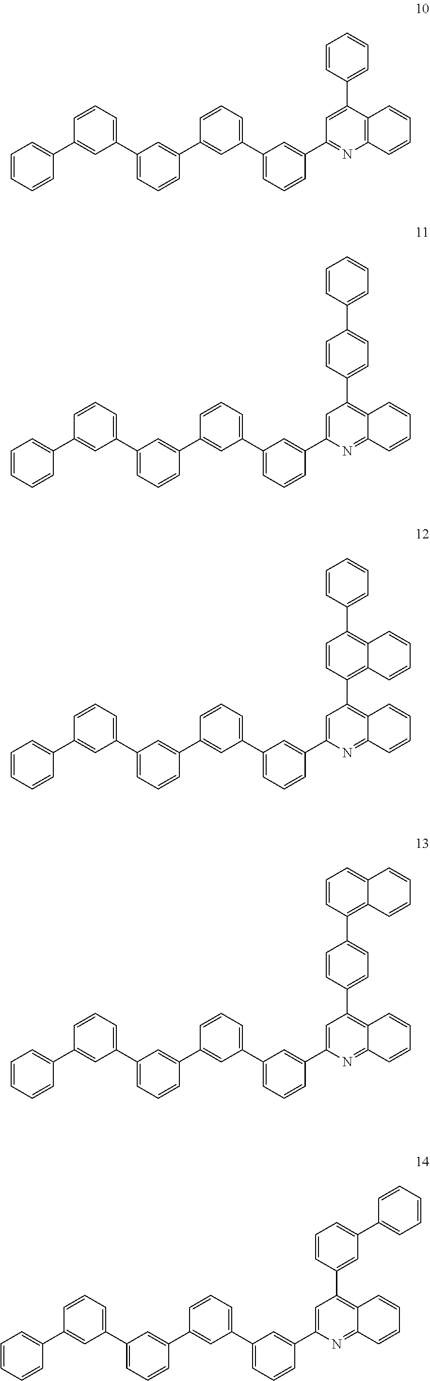


Applications Claiming Priority (5)
| Application Number | Priority Date | Filing Date | Title |
|---|---|---|---|
| KR20140061892 | 2014-05-22 | ||
| KR10-2014-0061892 | 2014-05-22 | ||
| KR10-2015-0053922 | 2015-04-16 | ||
| KR1020150053922A KR101897039B1 (en) | 2014-05-22 | 2015-04-16 | Organic compound and composition and organic optoelectric device and display device |
| PCT/KR2015/003882 WO2015178589A1 (en) | 2014-05-22 | 2015-04-17 | Organic compound, composition, organic electroluminescent device, and display device |
Publications (2)
| Publication Number | Publication Date |
|---|---|
| US20170047529A1 US20170047529A1 (en) | 2017-02-16 |
| US10446764B2 true US10446764B2 (en) | 2019-10-15 |
Family
ID=54883391
Family Applications (1)
| Application Number | Title | Priority Date | Filing Date |
|---|---|---|---|
| US15/307,108 Active US10446764B2 (en) | 2014-05-22 | 2015-04-17 | Organic compound, composition, organic optoelectric device, and display device |
Country Status (3)
| Country | Link |
|---|---|
| US (1) | US10446764B2 (en) |
| KR (1) | KR101897039B1 (en) |
| CN (1) | CN106414407B (en) |
Families Citing this family (6)
| Publication number | Priority date | Publication date | Assignee | Title |
|---|---|---|---|---|
| WO2019139233A1 (en) * | 2018-01-09 | 2019-07-18 | 주식회사 엘지화학 | Heterocyclic compound and organic light emitting element using same |
| KR102126884B1 (en) * | 2018-01-09 | 2020-06-25 | 주식회사 엘지화학 | Hetero-cyclic compound and organic light emitting device comprising the same |
| EP3696167A4 (en) | 2018-07-27 | 2021-03-24 | Idemitsu Kosan Co.,Ltd. | Compound, material for organic electroluminescence element, organic electroluminescence element, and electronic device |
| US20240008354A1 (en) * | 2020-12-11 | 2024-01-04 | Nippon Steel Chemical & Material Co., Ltd. | Organic electroluminescent element |
| CN116710534A (en) * | 2020-12-18 | 2023-09-05 | 日铁化学材料株式会社 | Organic electroluminescent element and method for manufacturing the same |
| CN113583004A (en) * | 2021-08-12 | 2021-11-02 | 陕西维世诺新材料有限公司 | Preparation method and application of biscarbazole and derivatives thereof |
Citations (38)
| Publication number | Priority date | Publication date | Assignee | Title |
|---|---|---|---|---|
| JPH083547A (en) * | 1994-03-31 | 1996-01-09 | Toray Ind Inc | Luminous element |
| JP2003040873A (en) | 2001-07-25 | 2003-02-13 | Idemitsu Kosan Co Ltd | New quinoxaline derivative and organic electroluminescent element utilizing the same |
| JP2003045662A (en) | 2001-08-01 | 2003-02-14 | Konica Corp | Organic electroluminescent element and display device |
| WO2005085387A1 (en) | 2004-03-08 | 2005-09-15 | Idemitsu Kosan Co., Ltd. | Material for organic electroluminescence device and organic electroluminescence device utilizing the same |
| WO2006104118A1 (en) | 2005-03-29 | 2006-10-05 | Konica Minolta Holdings, Inc. | Organic electroluminescent device, display and illuminating device |
| JP2007015993A (en) | 2005-07-08 | 2007-01-25 | Chemiprokasei Kaisha Ltd | New 1,3,5-triphenylbenzene derivative and organic electroluminescent element containing the same |
| JP3945032B2 (en) | 1998-08-10 | 2007-07-18 | 東洋インキ製造株式会社 | Luminescent material for organic electroluminescence device and organic electroluminescence device using the same |
| JP2008127446A (en) | 2006-11-20 | 2008-06-05 | Canon Inc | 1,5-naphthyridine compound and organic light emitting device |
| JP4158426B2 (en) | 2001-06-08 | 2008-10-01 | 東レ株式会社 | Light emitting element |
| US20090045731A1 (en) | 2007-07-07 | 2009-02-19 | Idemitsu Kosan Co., Ltd. | Organic electroluminescence device and material for organic electroluminescence device |
| US20090091240A1 (en) | 2004-11-04 | 2009-04-09 | Idemitsu Kosan Co., Ltd. | Compound containing fused ring and organic electroluminescent element employing the same |
| JP2009227663A (en) * | 2008-02-25 | 2009-10-08 | Mitsubishi Chemicals Corp | Quinoline compound, material for organic electroluminescent device, composition for organic electroluminescent device, organic electroluminescent device, organic el display, and organic el illumination |
| KR20090130008A (en) | 2007-04-12 | 2009-12-17 | 토소가부시키가이샤 | Phenyl-substituted 1,3,5-triazine compound, process for producing the same, and organic electroluminescent device containing the same as component |
| JP2010275255A (en) | 2009-05-29 | 2010-12-09 | Mitsubishi Chemicals Corp | Nitrogen-containing heterocyclic compound, organic electroluminescent element material, composition for organic electroluminescent element, organic electroluminescent element, organic el display and organic el lighting |
| KR20110077930A (en) * | 2009-12-30 | 2011-07-07 | 주식회사 두산 | Organic electroluminescent compounds and organic electroluminescent device comprising same |
| CN102439004A (en) | 2010-04-20 | 2012-05-02 | 出光兴产株式会社 | Bicarbazole derivative, material for organic electroluminescent element, and organic electroluminescent element using same |
| KR101144358B1 (en) | 2009-05-13 | 2012-05-11 | 덕산하이메탈(주) | Compound Containing 5-Membered Heterocycle And Organic Electronic Element Using The Same, Terminal Thereof |
| JP2012092047A (en) | 2010-10-27 | 2012-05-17 | Canon Inc | Pyrazoloindole compound, and organic light emitting element employing the same |
| JP2012121857A (en) | 2010-12-09 | 2012-06-28 | Canon Inc | Novel organic compound and organic light-emitting device including the same |
| KR20120102374A (en) | 2011-03-08 | 2012-09-18 | 롬엔드하스전자재료코리아유한회사 | Novel compounds for organic electronic material and organic electroluminescence device using the same |
| US8278651B2 (en) | 2008-12-22 | 2012-10-02 | E I Du Pont De Nemours And Company | Electronic device including 1,7-phenanthroline derivative |
| KR20120109744A (en) | 2011-03-25 | 2012-10-09 | 롬엔드하스전자재료코리아유한회사 | Novel compounds for organic electronic material and organic electroluminescence device using the same |
| WO2012137958A1 (en) | 2011-04-07 | 2012-10-11 | 三菱化学株式会社 | Organic compound, charge transport material, composition containing said compound, organic electroluminescent element, display device, and lighting device |
| KR101197218B1 (en) | 2009-04-03 | 2012-11-02 | 덕산하이메탈(주) | Quinoxaline DERIVATIVES AND ORGANIC ELECTRORIC ELEMENT USING THE SAME, TERMINAL THEREROF |
| JP5120398B2 (en) | 2010-03-04 | 2013-01-16 | コニカミノルタホールディングス株式会社 | Organic electroluminescence element and display device |
| KR101251624B1 (en) | 2003-04-18 | 2013-04-08 | 가부시키가이샤 한도오따이 에네루기 켄큐쇼 | Quinoxaline derivatives, and organic semiconductor devices, electroluminescent devices made by using the derivatives |
| CN103221406A (en) | 2010-09-17 | 2013-07-24 | 罗门哈斯电子材料韩国有限公司 | Novel organic electroluminescent compounds and organic electroluminescent device using the same |
| JP2013180979A (en) | 2012-03-01 | 2013-09-12 | Mitsubishi Chemicals Corp | Charge transport material, composition for charge transport film, organic electroluminescent device, organic el display, and organic el illumination |
| KR20130102673A (en) | 2012-03-08 | 2013-09-23 | 롬엔드하스전자재료코리아유한회사 | Novel organic electroluminescent compounds and organic electroluminescent device using the same |
| KR20130114785A (en) | 2012-04-10 | 2013-10-21 | 롬엔드하스전자재료코리아유한회사 | Novel organic electroluminescent compounds and organic electroluminescent device containing the same |
| JP5321710B2 (en) | 2012-04-06 | 2013-10-23 | コニカミノルタ株式会社 | Organic electroluminescence element and display device |
| KR20130119740A (en) | 2012-04-24 | 2013-11-01 | 제일모직주식회사 | Compound for organic optoelectronic device, organic light emitting diode including the same and display including the organic light emitting diode |
| JP5340999B2 (en) | 2010-03-04 | 2013-11-13 | コニカミノルタ株式会社 | Organic electroluminescence element and display device |
| KR20130139535A (en) | 2012-06-13 | 2013-12-23 | 롬엔드하스전자재료코리아유한회사 | Novel organic electroluminescence compounds and organic electroluminescence device containing the same |
| WO2014069637A1 (en) | 2012-11-02 | 2014-05-08 | コニカミノルタ株式会社 | Organic electroluminescent element, lighting device and display device |
| US20140131665A1 (en) | 2012-11-12 | 2014-05-15 | Universal Display Corporation | Organic Electroluminescent Device With Delayed Fluorescence |
| KR20140128653A (en) * | 2013-04-29 | 2014-11-06 | 덕산하이메탈(주) | Compound for organic electronic element, organic electronic element using the same, and an electronic device thereof |
| KR20150064410A (en) | 2013-12-03 | 2015-06-11 | 덕산네오룩스 주식회사 | Compound for organic electronic element, organic electronic element using the same, and an electronic device thereof |
Family Cites Families (1)
| Publication number | Priority date | Publication date | Assignee | Title |
|---|---|---|---|---|
| KR101375363B1 (en) * | 2012-07-23 | 2014-04-11 | 안국바이오진단(주) | Apparatus for measuring temperature using thermistor |
-
2015
- 2015-04-16 KR KR1020150053922A patent/KR101897039B1/en active IP Right Grant
- 2015-04-17 CN CN201580026671.8A patent/CN106414407B/en active Active
- 2015-04-17 US US15/307,108 patent/US10446764B2/en active Active
Patent Citations (45)
| Publication number | Priority date | Publication date | Assignee | Title |
|---|---|---|---|---|
| JPH083547A (en) * | 1994-03-31 | 1996-01-09 | Toray Ind Inc | Luminous element |
| JP3945032B2 (en) | 1998-08-10 | 2007-07-18 | 東洋インキ製造株式会社 | Luminescent material for organic electroluminescence device and organic electroluminescence device using the same |
| JP4158426B2 (en) | 2001-06-08 | 2008-10-01 | 東レ株式会社 | Light emitting element |
| JP2003040873A (en) | 2001-07-25 | 2003-02-13 | Idemitsu Kosan Co Ltd | New quinoxaline derivative and organic electroluminescent element utilizing the same |
| JP2003045662A (en) | 2001-08-01 | 2003-02-14 | Konica Corp | Organic electroluminescent element and display device |
| JP5135657B2 (en) | 2001-08-01 | 2013-02-06 | コニカミノルタホールディングス株式会社 | Organic electroluminescence element and display device |
| KR101251624B1 (en) | 2003-04-18 | 2013-04-08 | 가부시키가이샤 한도오따이 에네루기 켄큐쇼 | Quinoxaline derivatives, and organic semiconductor devices, electroluminescent devices made by using the derivatives |
| WO2005085387A1 (en) | 2004-03-08 | 2005-09-15 | Idemitsu Kosan Co., Ltd. | Material for organic electroluminescence device and organic electroluminescence device utilizing the same |
| US20090091240A1 (en) | 2004-11-04 | 2009-04-09 | Idemitsu Kosan Co., Ltd. | Compound containing fused ring and organic electroluminescent element employing the same |
| WO2006104118A1 (en) | 2005-03-29 | 2006-10-05 | Konica Minolta Holdings, Inc. | Organic electroluminescent device, display and illuminating device |
| JP2013038432A (en) | 2005-03-29 | 2013-02-21 | Konica Minolta Holdings Inc | Organic electroluminescent element |
| JP5266514B2 (en) | 2005-03-29 | 2013-08-21 | コニカミノルタ株式会社 | Organic electroluminescence device |
| JP2007015993A (en) | 2005-07-08 | 2007-01-25 | Chemiprokasei Kaisha Ltd | New 1,3,5-triphenylbenzene derivative and organic electroluminescent element containing the same |
| JP2008127446A (en) | 2006-11-20 | 2008-06-05 | Canon Inc | 1,5-naphthyridine compound and organic light emitting device |
| KR20090130008A (en) | 2007-04-12 | 2009-12-17 | 토소가부시키가이샤 | Phenyl-substituted 1,3,5-triazine compound, process for producing the same, and organic electroluminescent device containing the same as component |
| US20090045731A1 (en) | 2007-07-07 | 2009-02-19 | Idemitsu Kosan Co., Ltd. | Organic electroluminescence device and material for organic electroluminescence device |
| JP2009227663A (en) * | 2008-02-25 | 2009-10-08 | Mitsubishi Chemicals Corp | Quinoline compound, material for organic electroluminescent device, composition for organic electroluminescent device, organic electroluminescent device, organic el display, and organic el illumination |
| US8278651B2 (en) | 2008-12-22 | 2012-10-02 | E I Du Pont De Nemours And Company | Electronic device including 1,7-phenanthroline derivative |
| KR101197218B1 (en) | 2009-04-03 | 2012-11-02 | 덕산하이메탈(주) | Quinoxaline DERIVATIVES AND ORGANIC ELECTRORIC ELEMENT USING THE SAME, TERMINAL THEREROF |
| KR101144358B1 (en) | 2009-05-13 | 2012-05-11 | 덕산하이메탈(주) | Compound Containing 5-Membered Heterocycle And Organic Electronic Element Using The Same, Terminal Thereof |
| JP2010275255A (en) | 2009-05-29 | 2010-12-09 | Mitsubishi Chemicals Corp | Nitrogen-containing heterocyclic compound, organic electroluminescent element material, composition for organic electroluminescent element, organic electroluminescent element, organic el display and organic el lighting |
| WO2011081431A2 (en) * | 2009-12-30 | 2011-07-07 | 주식회사 두산 | Organic light emitting compound, and organic electroluminescent device using same |
| KR20110077930A (en) * | 2009-12-30 | 2011-07-07 | 주식회사 두산 | Organic electroluminescent compounds and organic electroluminescent device comprising same |
| JP5340999B2 (en) | 2010-03-04 | 2013-11-13 | コニカミノルタ株式会社 | Organic electroluminescence element and display device |
| JP5120398B2 (en) | 2010-03-04 | 2013-01-16 | コニカミノルタホールディングス株式会社 | Organic electroluminescence element and display device |
| CN102439004A (en) | 2010-04-20 | 2012-05-02 | 出光兴产株式会社 | Bicarbazole derivative, material for organic electroluminescent element, and organic electroluminescent element using same |
| CN103221406A (en) | 2010-09-17 | 2013-07-24 | 罗门哈斯电子材料韩国有限公司 | Novel organic electroluminescent compounds and organic electroluminescent device using the same |
| JP2012092047A (en) | 2010-10-27 | 2012-05-17 | Canon Inc | Pyrazoloindole compound, and organic light emitting element employing the same |
| JP2012121857A (en) | 2010-12-09 | 2012-06-28 | Canon Inc | Novel organic compound and organic light-emitting device including the same |
| KR20120102374A (en) | 2011-03-08 | 2012-09-18 | 롬엔드하스전자재료코리아유한회사 | Novel compounds for organic electronic material and organic electroluminescence device using the same |
| KR20120109744A (en) | 2011-03-25 | 2012-10-09 | 롬엔드하스전자재료코리아유한회사 | Novel compounds for organic electronic material and organic electroluminescence device using the same |
| CN103534251A (en) | 2011-03-25 | 2014-01-22 | 罗门哈斯电子材料韩国有限公司 | Novel compounds for organic electronic material and organic electroluminescent device using the same |
| WO2012137958A1 (en) | 2011-04-07 | 2012-10-11 | 三菱化学株式会社 | Organic compound, charge transport material, composition containing said compound, organic electroluminescent element, display device, and lighting device |
| JP2013180979A (en) | 2012-03-01 | 2013-09-12 | Mitsubishi Chemicals Corp | Charge transport material, composition for charge transport film, organic electroluminescent device, organic el display, and organic el illumination |
| KR20130102673A (en) | 2012-03-08 | 2013-09-23 | 롬엔드하스전자재료코리아유한회사 | Novel organic electroluminescent compounds and organic electroluminescent device using the same |
| JP5321710B2 (en) | 2012-04-06 | 2013-10-23 | コニカミノルタ株式会社 | Organic electroluminescence element and display device |
| KR20130114785A (en) | 2012-04-10 | 2013-10-21 | 롬엔드하스전자재료코리아유한회사 | Novel organic electroluminescent compounds and organic electroluminescent device containing the same |
| KR20130119740A (en) | 2012-04-24 | 2013-11-01 | 제일모직주식회사 | Compound for organic optoelectronic device, organic light emitting diode including the same and display including the organic light emitting diode |
| KR20130139535A (en) | 2012-06-13 | 2013-12-23 | 롬엔드하스전자재료코리아유한회사 | Novel organic electroluminescence compounds and organic electroluminescence device containing the same |
| WO2014069637A1 (en) | 2012-11-02 | 2014-05-08 | コニカミノルタ株式会社 | Organic electroluminescent element, lighting device and display device |
| US20140131665A1 (en) | 2012-11-12 | 2014-05-15 | Universal Display Corporation | Organic Electroluminescent Device With Delayed Fluorescence |
| JP2014096586A (en) | 2012-11-12 | 2014-05-22 | Universal Display Corp | Organic electroluminescent device with delayed fluorescence |
| KR20140128653A (en) * | 2013-04-29 | 2014-11-06 | 덕산하이메탈(주) | Compound for organic electronic element, organic electronic element using the same, and an electronic device thereof |
| WO2014178532A1 (en) * | 2013-04-29 | 2014-11-06 | 덕산하이메탈(주) | Compound for organic electrical element, organic electrical element using same, and electronic device thereof |
| KR20150064410A (en) | 2013-12-03 | 2015-06-11 | 덕산네오룩스 주식회사 | Compound for organic electronic element, organic electronic element using the same, and an electronic device thereof |
Non-Patent Citations (6)
| Title |
|---|
| Chinese Office Action dated Apr. 23, 2018, and the accompanying Search Report dated Apr. 12, 2018, of the corresponding Korean Patent Application No. 201580026671.8. |
| Machine English translation of Goromaru et al. (JP 2009-227663 A). Dec. 30, 2017. * |
| Machine English translation of Himeshima et al. (JP 08-3547). Dec. 30, 2017. * |
| Machine English translation of Lee et al. (KR-10-2011-0077930). (Year: 2018). * |
| Machine English translation of Okaniwa et al. (WO 2014/069637 A1). Dec. 30, 2017. * |
| Machine English translation of Park et al. (KR 10-2014-0128653). Dec. 30, 2017. * |
Also Published As
| Publication number | Publication date |
|---|---|
| CN106414407A (en) | 2017-02-15 |
| US20170047529A1 (en) | 2017-02-16 |
| KR20150135070A (en) | 2015-12-02 |
| CN106414407B (en) | 2019-07-12 |
| KR101897039B1 (en) | 2018-09-10 |
Similar Documents
| Publication | Publication Date | Title |
|---|---|---|
| US10797245B2 (en) | Compound for organic optoelectronic element, organic optoelectronic element, and display device | |
| US10050212B2 (en) | Organic optoelectric device and display device | |
| US10538510B2 (en) | Compound for organic optoelectronic device, composition for organic optoelectronic device and organic optoelectronic device and display device | |
| US10873033B2 (en) | Organic compound, composition, organic optoelectronic diode, and display device | |
| US20230255109A1 (en) | Compound, composition and organic optoelectronic device and display device | |
| US20170104163A1 (en) | Composition for organic optoelectric diode, organic optoelectric diode, and display device | |
| US10522766B2 (en) | Organic optoelectronic device and display device | |
| US10784447B2 (en) | Organic compound, composition, and organic optoelectronic diode | |
| US20160163995A1 (en) | Organic optoelectric device and display device | |
| US20160126472A1 (en) | Composition for organic optoelectronic device, organic optoelectronic device, and display device | |
| US20150349269A1 (en) | Luminescent material for organic optoelectric device and organic optoelectric device and display device | |
| US11844271B2 (en) | Organic compound, composition, organic optoelectronic device, and display apparatus | |
| US10516113B2 (en) | Organic compound, organic optoelectric device and display device | |
| US10644245B2 (en) | Composition for organic photoelectronic element, organic photoelectronic element, and display apparatus | |
| US20170084845A1 (en) | Organic optoelectronic device and display device | |
| US10446764B2 (en) | Organic compound, composition, organic optoelectric device, and display device | |
| US20210217963A1 (en) | Organic light-emitting device | |
| US20170309829A1 (en) | Composition for organic optoelectronic element, organic optoelectronic element, and display device | |
| US20170092873A1 (en) | Composition for organic optoelectronic device, organic optoelectronic device and display device | |
| US11605782B2 (en) | Organic optoelectronic device and display device | |
| US20210070706A1 (en) | Composition, organic optoelectronic device, and display device | |
| US20200144510A1 (en) | Organic optoelectronic device and display device | |
| US20220069226A1 (en) | Composition for organic optoelectronic element, organic optoelectronic element, and display device | |
| US20210257552A1 (en) | Organic light-emitting device | |
| US20200144508A1 (en) | Organic optoelectronic device and display device |
Legal Events
| Date | Code | Title | Description |
|---|---|---|---|
| AS | Assignment |
Owner name: SAMSUNG SDI CO., LTD., KOREA, REPUBLIC OF Free format text: ASSIGNMENT OF ASSIGNORS INTEREST;ASSIGNORS:MIN, SOOHYUN;KIM, YOUNGKWON;KIM, JUN SEOK;AND OTHERS;REEL/FRAME:040148/0956 Effective date: 20161014 |
|
| STPP | Information on status: patent application and granting procedure in general |
Free format text: NON FINAL ACTION MAILED |
|
| STPP | Information on status: patent application and granting procedure in general |
Free format text: RESPONSE TO NON-FINAL OFFICE ACTION ENTERED AND FORWARDED TO EXAMINER |
|
| STPP | Information on status: patent application and granting procedure in general |
Free format text: NOTICE OF ALLOWANCE MAILED -- APPLICATION RECEIVED IN OFFICE OF PUBLICATIONS |
|
| STPP | Information on status: patent application and granting procedure in general |
Free format text: PUBLICATIONS -- ISSUE FEE PAYMENT RECEIVED |
|
| STPP | Information on status: patent application and granting procedure in general |
Free format text: PUBLICATIONS -- ISSUE FEE PAYMENT VERIFIED |
|
| STCF | Information on status: patent grant |
Free format text: PATENTED CASE |
|
| MAFP | Maintenance fee payment |
Free format text: PAYMENT OF MAINTENANCE FEE, 4TH YEAR, LARGE ENTITY (ORIGINAL EVENT CODE: M1551); ENTITY STATUS OF PATENT OWNER: LARGE ENTITY Year of fee payment: 4 |