US10399960B2 - Dicyanopyrazine compound, luminescent material, luminescence device using the same, and method for producing 2,5-dicyano-3,6-dihalogenopyrazine - Google Patents
Dicyanopyrazine compound, luminescent material, luminescence device using the same, and method for producing 2,5-dicyano-3,6-dihalogenopyrazine Download PDFInfo
- Publication number
- US10399960B2 US10399960B2 US15/769,578 US201615769578A US10399960B2 US 10399960 B2 US10399960 B2 US 10399960B2 US 201615769578 A US201615769578 A US 201615769578A US 10399960 B2 US10399960 B2 US 10399960B2
- Authority
- US
- United States
- Prior art keywords
- group
- ring
- substituted
- unsubstituted
- compound
- Prior art date
- Legal status (The legal status is an assumption and is not a legal conclusion. Google has not performed a legal analysis and makes no representation as to the accuracy of the status listed.)
- Active
Links
- 239000000463 material Substances 0.000 title claims description 87
- 238000004020 luminiscence type Methods 0.000 title claims description 16
- -1 Dicyanopyrazine compound Chemical class 0.000 title description 135
- 238000004519 manufacturing process Methods 0.000 title description 9
- 150000001875 compounds Chemical class 0.000 claims abstract description 63
- 125000003118 aryl group Chemical group 0.000 claims abstract description 40
- 125000005549 heteroarylene group Chemical group 0.000 claims abstract description 21
- 125000000732 arylene group Chemical group 0.000 claims abstract description 20
- 125000004432 carbon atom Chemical group C* 0.000 claims abstract description 14
- 125000004435 hydrogen atom Chemical group [H]* 0.000 claims abstract description 10
- 125000001424 substituent group Chemical group 0.000 claims description 25
- 125000001072 heteroaryl group Chemical group 0.000 claims description 19
- 125000003277 amino group Chemical group 0.000 claims description 15
- 125000003373 pyrazinyl group Chemical group 0.000 claims description 15
- 125000005843 halogen group Chemical group 0.000 claims description 10
- 125000003837 (C1-C20) alkyl group Chemical group 0.000 claims description 7
- 125000000304 alkynyl group Chemical group 0.000 claims description 7
- 125000004414 alkyl thio group Chemical group 0.000 claims description 5
- 125000002883 imidazolyl group Chemical group 0.000 claims description 5
- 125000000842 isoxazolyl group Chemical group 0.000 claims description 5
- 125000002971 oxazolyl group Chemical group 0.000 claims description 5
- 125000003226 pyrazolyl group Chemical group 0.000 claims description 5
- 125000000714 pyrimidinyl group Chemical group 0.000 claims description 5
- 125000000168 pyrrolyl group Chemical group 0.000 claims description 5
- 125000003860 C1-C20 alkoxy group Chemical group 0.000 claims description 4
- 125000005103 alkyl silyl group Chemical group 0.000 claims description 4
- 125000002887 hydroxy group Chemical group [H]O* 0.000 claims description 4
- 125000001624 naphthyl group Chemical group 0.000 claims description 4
- GWYPDXLJACEENP-UHFFFAOYSA-N 1,3-cycloheptadiene Chemical group C1CC=CC=CC1 GWYPDXLJACEENP-UHFFFAOYSA-N 0.000 claims description 3
- 125000006374 C2-C10 alkenyl group Chemical group 0.000 claims description 3
- JUJWROOIHBZHMG-UHFFFAOYSA-N Pyridine Chemical group C1=CC=NC=C1 JUJWROOIHBZHMG-UHFFFAOYSA-N 0.000 claims description 3
- FZWLAAWBMGSTSO-UHFFFAOYSA-N Thiazole Chemical group C1=CSC=N1 FZWLAAWBMGSTSO-UHFFFAOYSA-N 0.000 claims description 3
- CHVJITGCYZJHLR-UHFFFAOYSA-N cyclohepta-1,3,5-triene Chemical group C1C=CC=CC=C1 CHVJITGCYZJHLR-UHFFFAOYSA-N 0.000 claims description 3
- 125000001162 cycloheptenyl group Chemical group C1(=CCCCCC1)* 0.000 claims description 3
- MGNZXYYWBUKAII-UHFFFAOYSA-N cyclohexa-1,3-diene Chemical group C1CC=CC=C1 MGNZXYYWBUKAII-UHFFFAOYSA-N 0.000 claims description 3
- 125000000596 cyclohexenyl group Chemical group C1(=CCCCC1)* 0.000 claims description 3
- 125000002433 cyclopentenyl group Chemical group C1(=CCCC1)* 0.000 claims description 3
- 125000002636 imidazolinyl group Chemical group 0.000 claims description 3
- ZLTPDFXIESTBQG-UHFFFAOYSA-N isothiazole Chemical group C=1C=NSC=1 ZLTPDFXIESTBQG-UHFFFAOYSA-N 0.000 claims description 3
- PBMFSQRYOILNGV-UHFFFAOYSA-N pyridazine Chemical group C1=CC=NN=C1 PBMFSQRYOILNGV-UHFFFAOYSA-N 0.000 claims description 3
- 239000010410 layer Substances 0.000 description 80
- 238000006243 chemical reaction Methods 0.000 description 54
- WEVYAHXRMPXWCK-UHFFFAOYSA-N Acetonitrile Chemical compound CC#N WEVYAHXRMPXWCK-UHFFFAOYSA-N 0.000 description 51
- YXFVVABEGXRONW-UHFFFAOYSA-N Toluene Chemical compound CC1=CC=CC=C1 YXFVVABEGXRONW-UHFFFAOYSA-N 0.000 description 45
- 238000005401 electroluminescence Methods 0.000 description 39
- 238000000034 method Methods 0.000 description 37
- 238000005424 photoluminescence Methods 0.000 description 32
- 239000000243 solution Substances 0.000 description 29
- 239000010408 film Substances 0.000 description 27
- VNDBCICANXNQOW-UHFFFAOYSA-N 3,6-diaminopyrazine-2,5-dicarbonitrile Chemical compound NC1=NC(C#N)=C(N)N=C1C#N VNDBCICANXNQOW-UHFFFAOYSA-N 0.000 description 24
- 238000000295 emission spectrum Methods 0.000 description 21
- 125000005842 heteroatom Chemical group 0.000 description 21
- 239000000758 substrate Substances 0.000 description 20
- 230000000903 blocking effect Effects 0.000 description 19
- 229910052799 carbon Inorganic materials 0.000 description 19
- 150000001721 carbon Chemical group 0.000 description 18
- QTMDXZNDVAMKGV-UHFFFAOYSA-L copper(ii) bromide Chemical compound [Cu+2].[Br-].[Br-] QTMDXZNDVAMKGV-UHFFFAOYSA-L 0.000 description 18
- 0 [3*]CC1=C(C[4*])N=C([N+]#[C-])C([N+]#[C-])=N1 Chemical compound [3*]CC1=C(C[4*])N=C([N+]#[C-])C([N+]#[C-])=N1 0.000 description 17
- 238000007792 addition Methods 0.000 description 17
- 239000007787 solid Substances 0.000 description 17
- HEDRZPFGACZZDS-MICDWDOJSA-N Trichloro(2H)methane Chemical compound [2H]C(Cl)(Cl)Cl HEDRZPFGACZZDS-MICDWDOJSA-N 0.000 description 16
- BZVZWWZUTZAEJY-UHFFFAOYSA-N 3,6-dibromopyrazine-2,5-dicarbonitrile Chemical compound BrC1=NC(C#N)=C(Br)N=C1C#N BZVZWWZUTZAEJY-UHFFFAOYSA-N 0.000 description 15
- 230000005525 hole transport Effects 0.000 description 14
- 238000002347 injection Methods 0.000 description 14
- 239000007924 injection Substances 0.000 description 14
- 238000007740 vapor deposition Methods 0.000 description 14
- 239000002904 solvent Substances 0.000 description 13
- IOVCWXUNBOPUCH-UHFFFAOYSA-M Nitrite anion Chemical compound [O-]N=O IOVCWXUNBOPUCH-UHFFFAOYSA-M 0.000 description 12
- 229910052751 metal Inorganic materials 0.000 description 12
- 239000002184 metal Substances 0.000 description 12
- 239000000203 mixture Substances 0.000 description 12
- 239000010409 thin film Substances 0.000 description 12
- 230000001052 transient effect Effects 0.000 description 12
- HEDRZPFGACZZDS-UHFFFAOYSA-N Chloroform Chemical compound ClC(Cl)Cl HEDRZPFGACZZDS-UHFFFAOYSA-N 0.000 description 10
- IAZDPXIOMUYVGZ-UHFFFAOYSA-N Dimethylsulphoxide Chemical compound CS(C)=O IAZDPXIOMUYVGZ-UHFFFAOYSA-N 0.000 description 10
- VYPSYNLAJGMNEJ-UHFFFAOYSA-N Silicium dioxide Chemical compound O=[Si]=O VYPSYNLAJGMNEJ-UHFFFAOYSA-N 0.000 description 10
- 125000003367 polycyclic group Chemical group 0.000 description 10
- XLYOFNOQVPJJNP-UHFFFAOYSA-N water Substances O XLYOFNOQVPJJNP-UHFFFAOYSA-N 0.000 description 10
- 229910021590 Copper(II) bromide Inorganic materials 0.000 description 9
- YMWUJEATGCHHMB-UHFFFAOYSA-N Dichloromethane Chemical compound ClCCl YMWUJEATGCHHMB-UHFFFAOYSA-N 0.000 description 9
- OKKJLVBELUTLKV-UHFFFAOYSA-N Methanol Chemical compound OC OKKJLVBELUTLKV-UHFFFAOYSA-N 0.000 description 9
- ZMXDDKWLCZADIW-UHFFFAOYSA-N N,N-Dimethylformamide Chemical compound CN(C)C=O ZMXDDKWLCZADIW-UHFFFAOYSA-N 0.000 description 9
- 230000021615 conjugation Effects 0.000 description 9
- OTVZGAXESBAAQQ-UHFFFAOYSA-N pyrazine-2,3-dicarbonitrile Chemical group N#CC1=NC=CN=C1C#N OTVZGAXESBAAQQ-UHFFFAOYSA-N 0.000 description 9
- IJGRMHOSHXDMSA-UHFFFAOYSA-N Atomic nitrogen Chemical compound N#N IJGRMHOSHXDMSA-UHFFFAOYSA-N 0.000 description 8
- XTHFKEDIFFGKHM-UHFFFAOYSA-N Dimethoxyethane Chemical compound COCCOC XTHFKEDIFFGKHM-UHFFFAOYSA-N 0.000 description 8
- LFQSCWFLJHTTHZ-UHFFFAOYSA-N Ethanol Chemical compound CCO LFQSCWFLJHTTHZ-UHFFFAOYSA-N 0.000 description 8
- 229910052782 aluminium Inorganic materials 0.000 description 8
- XAGFODPZIPBFFR-UHFFFAOYSA-N aluminium Chemical compound [Al] XAGFODPZIPBFFR-UHFFFAOYSA-N 0.000 description 8
- 229910052757 nitrogen Inorganic materials 0.000 description 8
- 239000012299 nitrogen atmosphere Substances 0.000 description 8
- 125000001997 phenyl group Chemical group [H]C1=C([H])C([H])=C(*)C([H])=C1[H] 0.000 description 8
- 238000003756 stirring Methods 0.000 description 8
- IOVCWXUNBOPUCH-UHFFFAOYSA-N Nitrous acid Chemical compound ON=O IOVCWXUNBOPUCH-UHFFFAOYSA-N 0.000 description 7
- 239000003795 chemical substances by application Substances 0.000 description 7
- 238000000746 purification Methods 0.000 description 7
- 238000004528 spin coating Methods 0.000 description 7
- IOGXOCVLYRDXLW-UHFFFAOYSA-N tert-butyl nitrite Chemical compound CC(C)(C)ON=O IOGXOCVLYRDXLW-UHFFFAOYSA-N 0.000 description 7
- ZWEHNKRNPOVVGH-UHFFFAOYSA-N 2-Butanone Chemical compound CCC(C)=O ZWEHNKRNPOVVGH-UHFFFAOYSA-N 0.000 description 6
- UHOVQNZJYSORNB-UHFFFAOYSA-N Benzene Chemical compound C1=CC=CC=C1 UHOVQNZJYSORNB-UHFFFAOYSA-N 0.000 description 6
- RTZKZFJDLAIYFH-UHFFFAOYSA-N Diethyl ether Chemical compound CCOCC RTZKZFJDLAIYFH-UHFFFAOYSA-N 0.000 description 6
- XEKOWRVHYACXOJ-UHFFFAOYSA-N Ethyl acetate Chemical compound CCOC(C)=O XEKOWRVHYACXOJ-UHFFFAOYSA-N 0.000 description 6
- 125000003342 alkenyl group Chemical group 0.000 description 6
- 230000003111 delayed effect Effects 0.000 description 6
- 239000000706 filtrate Substances 0.000 description 6
- 230000002140 halogenating effect Effects 0.000 description 6
- PQXKHYXIUOZZFA-UHFFFAOYSA-M lithium fluoride Chemical compound [Li+].[F-] PQXKHYXIUOZZFA-UHFFFAOYSA-M 0.000 description 6
- MXQOYLRVSVOCQT-UHFFFAOYSA-N palladium;tritert-butylphosphane Chemical compound [Pd].CC(C)(C)P(C(C)(C)C)C(C)(C)C.CC(C)(C)P(C(C)(C)C)C(C)(C)C MXQOYLRVSVOCQT-UHFFFAOYSA-N 0.000 description 6
- BWHMMNNQKKPAPP-UHFFFAOYSA-L potassium carbonate Chemical compound [K+].[K+].[O-]C([O-])=O BWHMMNNQKKPAPP-UHFFFAOYSA-L 0.000 description 6
- 239000007858 starting material Substances 0.000 description 6
- 238000005160 1H NMR spectroscopy Methods 0.000 description 5
- VEXZGXHMUGYJMC-UHFFFAOYSA-N Hydrochloric acid Chemical compound Cl VEXZGXHMUGYJMC-UHFFFAOYSA-N 0.000 description 5
- 150000001555 benzenes Chemical class 0.000 description 5
- 238000000576 coating method Methods 0.000 description 5
- 229920001940 conductive polymer Polymers 0.000 description 5
- 238000001840 matrix-assisted laser desorption--ionisation time-of-flight mass spectrometry Methods 0.000 description 5
- 239000011259 mixed solution Substances 0.000 description 5
- 125000002950 monocyclic group Chemical group 0.000 description 5
- 239000012044 organic layer Substances 0.000 description 5
- 239000010453 quartz Substances 0.000 description 5
- 229920006395 saturated elastomer Polymers 0.000 description 5
- 239000002356 single layer Substances 0.000 description 5
- 238000006467 substitution reaction Methods 0.000 description 5
- 125000004169 (C1-C6) alkyl group Chemical group 0.000 description 4
- DPZSNGJNFHWQDC-ARJAWSKDSA-N (z)-2,3-diaminobut-2-enedinitrile Chemical compound N#CC(/N)=C(/N)C#N DPZSNGJNFHWQDC-ARJAWSKDSA-N 0.000 description 4
- MYKQKWIPLZEVOW-UHFFFAOYSA-N 11h-benzo[a]carbazole Chemical compound C1=CC2=CC=CC=C2C2=C1C1=CC=CC=C1N2 MYKQKWIPLZEVOW-UHFFFAOYSA-N 0.000 description 4
- 238000001644 13C nuclear magnetic resonance spectroscopy Methods 0.000 description 4
- LSKHCUUIHXQQLK-UHFFFAOYSA-N 5,6-bis(4-bromophenyl)pyrazine-2,3-dicarbonitrile Chemical compound C1=CC(Br)=CC=C1C1=NC(C#N)=C(C#N)N=C1C1=CC=C(Br)C=C1 LSKHCUUIHXQQLK-UHFFFAOYSA-N 0.000 description 4
- CSCPPACGZOOCGX-UHFFFAOYSA-N Acetone Chemical compound CC(C)=O CSCPPACGZOOCGX-UHFFFAOYSA-N 0.000 description 4
- JQJPBYFTQAANLE-UHFFFAOYSA-N Butyl nitrite Chemical compound CCCCON=O JQJPBYFTQAANLE-UHFFFAOYSA-N 0.000 description 4
- FYYHWMGAXLPEAU-UHFFFAOYSA-N Magnesium Chemical compound [Mg] FYYHWMGAXLPEAU-UHFFFAOYSA-N 0.000 description 4
- PXHVJJICTQNCMI-UHFFFAOYSA-N Nickel Chemical compound [Ni] PXHVJJICTQNCMI-UHFFFAOYSA-N 0.000 description 4
- KDLHZDBZIXYQEI-UHFFFAOYSA-N Palladium Chemical compound [Pd] KDLHZDBZIXYQEI-UHFFFAOYSA-N 0.000 description 4
- PCNDJXKNXGMECE-UHFFFAOYSA-N Phenazine Natural products C1=CC=CC2=NC3=CC=CC=C3N=C21 PCNDJXKNXGMECE-UHFFFAOYSA-N 0.000 description 4
- KYQCOXFCLRTKLS-UHFFFAOYSA-N Pyrazine Natural products C1=CN=CC=N1 KYQCOXFCLRTKLS-UHFFFAOYSA-N 0.000 description 4
- BQCADISMDOOEFD-UHFFFAOYSA-N Silver Chemical compound [Ag] BQCADISMDOOEFD-UHFFFAOYSA-N 0.000 description 4
- WYURNTSHIVDZCO-UHFFFAOYSA-N Tetrahydrofuran Chemical compound C1CCOC1 WYURNTSHIVDZCO-UHFFFAOYSA-N 0.000 description 4
- 238000000862 absorption spectrum Methods 0.000 description 4
- 150000008043 acidic salts Chemical class 0.000 description 4
- QVGXLLKOCUKJST-UHFFFAOYSA-N atomic oxygen Chemical compound [O] QVGXLLKOCUKJST-UHFFFAOYSA-N 0.000 description 4
- 230000005587 bubbling Effects 0.000 description 4
- 150000001716 carbazoles Chemical class 0.000 description 4
- 239000011248 coating agent Substances 0.000 description 4
- 239000000470 constituent Substances 0.000 description 4
- 125000004093 cyano group Chemical group *C#N 0.000 description 4
- 125000004122 cyclic group Chemical group 0.000 description 4
- 238000000151 deposition Methods 0.000 description 4
- 239000011521 glass Substances 0.000 description 4
- 238000005658 halogenation reaction Methods 0.000 description 4
- OWFXIOWLTKNBAP-UHFFFAOYSA-N isoamyl nitrite Chemical compound CC(C)CCON=O OWFXIOWLTKNBAP-UHFFFAOYSA-N 0.000 description 4
- 239000011777 magnesium Substances 0.000 description 4
- 229910052749 magnesium Inorganic materials 0.000 description 4
- IBHBKWKFFTZAHE-UHFFFAOYSA-N n-[4-[4-(n-naphthalen-1-ylanilino)phenyl]phenyl]-n-phenylnaphthalen-1-amine Chemical compound C1=CC=CC=C1N(C=1C2=CC=CC=C2C=CC=1)C1=CC=C(C=2C=CC(=CC=2)N(C=2C=CC=CC=2)C=2C3=CC=CC=C3C=CC=2)C=C1 IBHBKWKFFTZAHE-UHFFFAOYSA-N 0.000 description 4
- 230000003287 optical effect Effects 0.000 description 4
- 239000003960 organic solvent Substances 0.000 description 4
- 229910052760 oxygen Inorganic materials 0.000 description 4
- 239000001301 oxygen Substances 0.000 description 4
- BASFCYQUMIYNBI-UHFFFAOYSA-N platinum Chemical compound [Pt] BASFCYQUMIYNBI-UHFFFAOYSA-N 0.000 description 4
- 239000000047 product Substances 0.000 description 4
- 125000001567 quinoxalinyl group Chemical group N1=C(C=NC2=CC=CC=C12)* 0.000 description 4
- 238000010898 silica gel chromatography Methods 0.000 description 4
- 229910052709 silver Inorganic materials 0.000 description 4
- 239000004332 silver Substances 0.000 description 4
- 239000000126 substance Substances 0.000 description 4
- WCXKTQVEKDHQIY-UHFFFAOYSA-N 3-[3-[3-(3,5-dipyridin-3-ylphenyl)phenyl]-5-pyridin-3-ylphenyl]pyridine Chemical compound C1=CN=CC(C=2C=C(C=C(C=2)C=2C=NC=CC=2)C=2C=C(C=CC=2)C=2C=C(C=C(C=2)C=2C=NC=CC=2)C=2C=NC=CC=2)=C1 WCXKTQVEKDHQIY-UHFFFAOYSA-N 0.000 description 3
- ZOKIJILZFXPFTO-UHFFFAOYSA-N 4-methyl-n-[4-[1-[4-(4-methyl-n-(4-methylphenyl)anilino)phenyl]cyclohexyl]phenyl]-n-(4-methylphenyl)aniline Chemical compound C1=CC(C)=CC=C1N(C=1C=CC(=CC=1)C1(CCCCC1)C=1C=CC(=CC=1)N(C=1C=CC(C)=CC=1)C=1C=CC(C)=CC=1)C1=CC=C(C)C=C1 ZOKIJILZFXPFTO-UHFFFAOYSA-N 0.000 description 3
- XLOMVQKBTHCTTD-UHFFFAOYSA-N Zinc monoxide Chemical compound [Zn]=O XLOMVQKBTHCTTD-UHFFFAOYSA-N 0.000 description 3
- 239000002253 acid Substances 0.000 description 3
- 150000001298 alcohols Chemical class 0.000 description 3
- 125000000217 alkyl group Chemical group 0.000 description 3
- 239000012298 atmosphere Substances 0.000 description 3
- 125000004429 atom Chemical group 0.000 description 3
- 230000004888 barrier function Effects 0.000 description 3
- 125000003785 benzimidazolyl group Chemical group N1=C(NC2=C1C=CC=C2)* 0.000 description 3
- 230000015572 biosynthetic process Effects 0.000 description 3
- 125000001246 bromo group Chemical group Br* 0.000 description 3
- 239000012141 concentrate Substances 0.000 description 3
- 230000000694 effects Effects 0.000 description 3
- 238000011156 evaluation Methods 0.000 description 3
- 239000004744 fabric Substances 0.000 description 3
- 239000010419 fine particle Substances 0.000 description 3
- 238000005187 foaming Methods 0.000 description 3
- 239000007789 gas Substances 0.000 description 3
- 125000000623 heterocyclic group Chemical group 0.000 description 3
- VLKZOEOYAKHREP-UHFFFAOYSA-N hexane Substances CCCCCC VLKZOEOYAKHREP-UHFFFAOYSA-N 0.000 description 3
- 239000012456 homogeneous solution Substances 0.000 description 3
- 150000002430 hydrocarbons Chemical group 0.000 description 3
- 229910044991 metal oxide Inorganic materials 0.000 description 3
- 150000004706 metal oxides Chemical class 0.000 description 3
- 150000002826 nitrites Chemical class 0.000 description 3
- 239000012074 organic phase Substances 0.000 description 3
- 150000007978 oxazole derivatives Chemical class 0.000 description 3
- 229910000027 potassium carbonate Inorganic materials 0.000 description 3
- NLKNQRATVPKPDG-UHFFFAOYSA-M potassium iodide Chemical compound [K+].[I-] NLKNQRATVPKPDG-UHFFFAOYSA-M 0.000 description 3
- 150000004322 quinolinols Chemical class 0.000 description 3
- 238000010992 reflux Methods 0.000 description 3
- 229920005989 resin Polymers 0.000 description 3
- 239000011347 resin Substances 0.000 description 3
- 229920003002 synthetic resin Polymers 0.000 description 3
- 239000000057 synthetic resin Substances 0.000 description 3
- RYHBNJHYFVUHQT-UHFFFAOYSA-N 1,4-Dioxane Chemical compound C1COCCO1 RYHBNJHYFVUHQT-UHFFFAOYSA-N 0.000 description 2
- 125000004973 1-butenyl group Chemical group C(=CCC)* 0.000 description 2
- 125000004972 1-butynyl group Chemical group [H]C([H])([H])C([H])([H])C#C* 0.000 description 2
- 125000006039 1-hexenyl group Chemical group 0.000 description 2
- 125000006028 1-methyl-2-butenyl group Chemical group 0.000 description 2
- 125000006021 1-methyl-2-propenyl group Chemical group 0.000 description 2
- 125000001637 1-naphthyl group Chemical group [H]C1=C([H])C([H])=C2C(*)=C([H])C([H])=C([H])C2=C1[H] 0.000 description 2
- 125000006017 1-propenyl group Chemical group 0.000 description 2
- 125000000530 1-propynyl group Chemical group [H]C([H])([H])C#C* 0.000 description 2
- XHLHPRDBBAGVEG-UHFFFAOYSA-N 1-tetralone Chemical compound C1=CC=C2C(=O)CCCC2=C1 XHLHPRDBBAGVEG-UHFFFAOYSA-N 0.000 description 2
- 125000004201 2,4-dichlorophenyl group Chemical group [H]C1=C([H])C(*)=C(Cl)C([H])=C1Cl 0.000 description 2
- 125000004974 2-butenyl group Chemical group C(C=CC)* 0.000 description 2
- 125000000069 2-butynyl group Chemical group [H]C([H])([H])C#CC([H])([H])* 0.000 description 2
- 125000006040 2-hexenyl group Chemical group 0.000 description 2
- 125000006029 2-methyl-2-butenyl group Chemical group 0.000 description 2
- 125000006022 2-methyl-2-propenyl group Chemical group 0.000 description 2
- 125000001622 2-naphthyl group Chemical group [H]C1=C([H])C([H])=C2C([H])=C(*)C([H])=C([H])C2=C1[H] 0.000 description 2
- 125000006024 2-pentenyl group Chemical group 0.000 description 2
- 125000003903 2-propenyl group Chemical group [H]C([*])([H])C([H])=C([H])[H] 0.000 description 2
- 125000001494 2-propynyl group Chemical group [H]C#CC([H])([H])* 0.000 description 2
- 125000004189 3,4-dichlorophenyl group Chemical group [H]C1=C([H])C(Cl)=C(Cl)C([H])=C1* 0.000 description 2
- 125000003762 3,4-dimethoxyphenyl group Chemical group [H]C1=C([H])C(OC([H])([H])[H])=C(OC([H])([H])[H])C([H])=C1* 0.000 description 2
- QENGPZGAWFQWCZ-UHFFFAOYSA-N 3-Methylthiophene Chemical compound CC=1C=CSC=1 QENGPZGAWFQWCZ-UHFFFAOYSA-N 0.000 description 2
- GPIZLEHIVRHDAW-UHFFFAOYSA-N 3-aminopyrazine-2-carbonitrile Chemical compound NC1=NC=CN=C1C#N GPIZLEHIVRHDAW-UHFFFAOYSA-N 0.000 description 2
- 125000004975 3-butenyl group Chemical group C(CC=C)* 0.000 description 2
- 125000000474 3-butynyl group Chemical group [H]C#CC([H])([H])C([H])([H])* 0.000 description 2
- 125000006041 3-hexenyl group Chemical group 0.000 description 2
- AWXGSYPUMWKTBR-UHFFFAOYSA-N 4-carbazol-9-yl-n,n-bis(4-carbazol-9-ylphenyl)aniline Chemical compound C12=CC=CC=C2C2=CC=CC=C2N1C1=CC=C(N(C=2C=CC(=CC=2)N2C3=CC=CC=C3C3=CC=CC=C32)C=2C=CC(=CC=2)N2C3=CC=CC=C3C3=CC=CC=C32)C=C1 AWXGSYPUMWKTBR-UHFFFAOYSA-N 0.000 description 2
- 125000001255 4-fluorophenyl group Chemical group [H]C1=C([H])C(*)=C([H])C([H])=C1F 0.000 description 2
- 125000006042 4-hexenyl group Chemical group 0.000 description 2
- 125000004172 4-methoxyphenyl group Chemical group [H]C1=C([H])C(OC([H])([H])[H])=C([H])C([H])=C1* 0.000 description 2
- 125000004863 4-trifluoromethoxyphenyl group Chemical group [H]C1=C([H])C(OC(F)(F)F)=C([H])C([H])=C1* 0.000 description 2
- 125000004199 4-trifluoromethylphenyl group Chemical group [H]C1=C([H])C(=C([H])C([H])=C1*)C(F)(F)F 0.000 description 2
- CZVMKUGOIQKZTJ-UHFFFAOYSA-N 5,6-bis(4-phenoxazin-10-ylphenyl)pyrazine-2,3-dicarbonitrile Chemical compound C1=CC=CC=2OC3=CC=CC=C3N(C1=2)C1=CC=C(C=C1)C=1N=C(C(=NC=1C1=CC=C(C=C1)N1C2=CC=CC=C2OC=2C=CC=CC1=2)C#N)C#N CZVMKUGOIQKZTJ-UHFFFAOYSA-N 0.000 description 2
- 125000006043 5-hexenyl group Chemical group 0.000 description 2
- 125000006163 5-membered heteroaryl group Chemical group 0.000 description 2
- UPUQYBJFFYMNQK-UHFFFAOYSA-N 6,11-dihydro-5h-benzo[a]carbazole Chemical compound N1C2=CC=CC=C2C2=C1C1=CC=CC=C1CC2 UPUQYBJFFYMNQK-UHFFFAOYSA-N 0.000 description 2
- 125000006164 6-membered heteroaryl group Chemical group 0.000 description 2
- MZYDBGLUVPLRKR-UHFFFAOYSA-N 9-(3-carbazol-9-ylphenyl)carbazole Chemical compound C12=CC=CC=C2C2=CC=CC=C2N1C1=CC(N2C3=CC=CC=C3C3=CC=CC=C32)=CC=C1 MZYDBGLUVPLRKR-UHFFFAOYSA-N 0.000 description 2
- PAYRUJLWNCNPSJ-UHFFFAOYSA-N Aniline Chemical compound NC1=CC=CC=C1 PAYRUJLWNCNPSJ-UHFFFAOYSA-N 0.000 description 2
- ROFVEXUMMXZLPA-UHFFFAOYSA-N Bipyridyl Chemical group N1=CC=CC=C1C1=CC=CC=N1 ROFVEXUMMXZLPA-UHFFFAOYSA-N 0.000 description 2
- WKBOTKDWSSQWDR-UHFFFAOYSA-N Bromine atom Chemical compound [Br] WKBOTKDWSSQWDR-UHFFFAOYSA-N 0.000 description 2
- SAIJUVYQZZJJPP-UHFFFAOYSA-N CC.CC.CC.CC.CC.CC.CC.CC.CC.CC.CC.CC.CC.CC.CN1C2=C(C=CC=C2)/N=C\1C1=CC=CC=C1.CN1C2=C(C=CC=C2)C2=C1/C=C\C=C/2.CN1C2=C(C=CC=C2)CC2=C1C=CC=C2.CN1C2=C(C=CC=C2)N(C2=CC=CC=C2)C2=C1C=CC=C2.CN1C2=C(C=CC=C2)OC2=C1C=CC=C2.CN1C2=C(C=CC=C2)SC2=C1C=CC=C2 Chemical compound CC.CC.CC.CC.CC.CC.CC.CC.CC.CC.CC.CC.CC.CC.CN1C2=C(C=CC=C2)/N=C\1C1=CC=CC=C1.CN1C2=C(C=CC=C2)C2=C1/C=C\C=C/2.CN1C2=C(C=CC=C2)CC2=C1C=CC=C2.CN1C2=C(C=CC=C2)N(C2=CC=CC=C2)C2=C1C=CC=C2.CN1C2=C(C=CC=C2)OC2=C1C=CC=C2.CN1C2=C(C=CC=C2)SC2=C1C=CC=C2 SAIJUVYQZZJJPP-UHFFFAOYSA-N 0.000 description 2
- WFXOHRWMOPZSQW-UHFFFAOYSA-N CC.CC.CN(C1=CC=CC=C1)C1=CC=CC=C1 Chemical compound CC.CC.CN(C1=CC=CC=C1)C1=CC=CC=C1 WFXOHRWMOPZSQW-UHFFFAOYSA-N 0.000 description 2
- AEXSVKUGKIJFCD-UHFFFAOYSA-N CC1(C)c2ccccc2N(c(cc2)ccc2-c2c(C#N)nc(-c(cc3)ccc3N3c4ccccc4C(C)(C)c4ccccc34)c(C#N)n2)c2c1cccc2 Chemical compound CC1(C)c2ccccc2N(c(cc2)ccc2-c2c(C#N)nc(-c(cc3)ccc3N3c4ccccc4C(C)(C)c4ccccc34)c(C#N)n2)c2c1cccc2 AEXSVKUGKIJFCD-UHFFFAOYSA-N 0.000 description 2
- OKTJSMMVPCPJKN-UHFFFAOYSA-N Carbon Chemical compound [C] OKTJSMMVPCPJKN-UHFFFAOYSA-N 0.000 description 2
- 101000837344 Homo sapiens T-cell leukemia translocation-altered gene protein Proteins 0.000 description 2
- WHXSMMKQMYFTQS-UHFFFAOYSA-N Lithium Chemical compound [Li] WHXSMMKQMYFTQS-UHFFFAOYSA-N 0.000 description 2
- CTQNGGLPUBDAKN-UHFFFAOYSA-N O-Xylene Chemical compound CC1=CC=CC=C1C CTQNGGLPUBDAKN-UHFFFAOYSA-N 0.000 description 2
- URLKBWYHVLBVBO-UHFFFAOYSA-N Para-Xylene Chemical group CC1=CC=C(C)C=C1 URLKBWYHVLBVBO-UHFFFAOYSA-N 0.000 description 2
- 229920001609 Poly(3,4-ethylenedioxythiophene) Polymers 0.000 description 2
- XUIMIQQOPSSXEZ-UHFFFAOYSA-N Silicon Chemical group [Si] XUIMIQQOPSSXEZ-UHFFFAOYSA-N 0.000 description 2
- 102100028692 T-cell leukemia translocation-altered gene protein Human genes 0.000 description 2
- 239000003929 acidic solution Substances 0.000 description 2
- 230000002378 acidificating effect Effects 0.000 description 2
- 125000003545 alkoxy group Chemical group 0.000 description 2
- MWPLVEDNUUSJAV-UHFFFAOYSA-N anthracene Chemical compound C1=CC=CC2=CC3=CC=CC=C3C=C21 MWPLVEDNUUSJAV-UHFFFAOYSA-N 0.000 description 2
- 125000003710 aryl alkyl group Chemical group 0.000 description 2
- 125000004104 aryloxy group Chemical group 0.000 description 2
- 125000003828 azulenyl group Chemical group 0.000 description 2
- 125000004618 benzofuryl group Chemical group O1C(=CC2=C1C=CC=C2)* 0.000 description 2
- 125000001164 benzothiazolyl group Chemical group S1C(=NC2=C1C=CC=C2)* 0.000 description 2
- 125000004196 benzothienyl group Chemical group S1C(=CC2=C1C=CC=C2)* 0.000 description 2
- 125000004541 benzoxazolyl group Chemical group O1C(=NC2=C1C=CC=C2)* 0.000 description 2
- 238000007664 blowing Methods 0.000 description 2
- GDTBXPJZTBHREO-UHFFFAOYSA-N bromine Substances BrBr GDTBXPJZTBHREO-UHFFFAOYSA-N 0.000 description 2
- 229910052794 bromium Inorganic materials 0.000 description 2
- 239000007853 buffer solution Substances 0.000 description 2
- XJHCXCQVJFPJIK-UHFFFAOYSA-M caesium fluoride Chemical compound [F-].[Cs+] XJHCXCQVJFPJIK-UHFFFAOYSA-M 0.000 description 2
- 239000006229 carbon black Substances 0.000 description 2
- 239000011203 carbon fibre reinforced carbon Substances 0.000 description 2
- ORTQZVOHEJQUHG-UHFFFAOYSA-L copper(II) chloride Chemical compound Cl[Cu]Cl ORTQZVOHEJQUHG-UHFFFAOYSA-L 0.000 description 2
- GBRBMTNGQBKBQE-UHFFFAOYSA-L copper;diiodide Chemical compound I[Cu]I GBRBMTNGQBKBQE-UHFFFAOYSA-L 0.000 description 2
- 239000013078 crystal Substances 0.000 description 2
- 125000005879 dioxolanyl group Chemical group 0.000 description 2
- 239000002019 doping agent Substances 0.000 description 2
- 150000002148 esters Chemical class 0.000 description 2
- 150000002170 ethers Chemical class 0.000 description 2
- 125000001301 ethoxy group Chemical group [H]C([H])([H])C([H])([H])O* 0.000 description 2
- 125000002534 ethynyl group Chemical group [H]C#C* 0.000 description 2
- 230000005284 excitation Effects 0.000 description 2
- 125000002541 furyl group Chemical group 0.000 description 2
- PCHJSUWPFVWCPO-UHFFFAOYSA-N gold Chemical compound [Au] PCHJSUWPFVWCPO-UHFFFAOYSA-N 0.000 description 2
- 229910052737 gold Inorganic materials 0.000 description 2
- 239000010931 gold Substances 0.000 description 2
- 150000008282 halocarbons Chemical class 0.000 description 2
- 230000020169 heat generation Effects 0.000 description 2
- 229930195733 hydrocarbon Natural products 0.000 description 2
- 125000003392 indanyl group Chemical group C1(CCC2=CC=CC=C12)* 0.000 description 2
- 229910052738 indium Inorganic materials 0.000 description 2
- APFVFJFRJDLVQX-UHFFFAOYSA-N indium atom Chemical compound [In] APFVFJFRJDLVQX-UHFFFAOYSA-N 0.000 description 2
- AMGQUBHHOARCQH-UHFFFAOYSA-N indium;oxotin Chemical compound [In].[Sn]=O AMGQUBHHOARCQH-UHFFFAOYSA-N 0.000 description 2
- 125000001041 indolyl group Chemical group 0.000 description 2
- 239000000543 intermediate Substances 0.000 description 2
- APNSGVMLAYLYCT-UHFFFAOYSA-N isobutyl nitrite Chemical compound CC(C)CON=O APNSGVMLAYLYCT-UHFFFAOYSA-N 0.000 description 2
- 125000005956 isoquinolyl group Chemical group 0.000 description 2
- 125000001786 isothiazolyl group Chemical group 0.000 description 2
- 150000002576 ketones Chemical class 0.000 description 2
- 229910052744 lithium Inorganic materials 0.000 description 2
- 150000002739 metals Chemical class 0.000 description 2
- 229910052759 nickel Inorganic materials 0.000 description 2
- 150000002825 nitriles Chemical class 0.000 description 2
- 150000004866 oxadiazoles Chemical class 0.000 description 2
- 125000001715 oxadiazolyl group Chemical group 0.000 description 2
- 230000001590 oxidative effect Effects 0.000 description 2
- TWNQGVIAIRXVLR-UHFFFAOYSA-N oxo(oxoalumanyloxy)alumane Chemical compound O=[Al]O[Al]=O TWNQGVIAIRXVLR-UHFFFAOYSA-N 0.000 description 2
- 125000003854 p-chlorophenyl group Chemical group [H]C1=C([H])C(*)=C([H])C([H])=C1Cl 0.000 description 2
- 229910052763 palladium Inorganic materials 0.000 description 2
- 125000000843 phenylene group Chemical group C1(=C(C=CC=C1)*)* 0.000 description 2
- 229910052697 platinum Inorganic materials 0.000 description 2
- 229920001467 poly(styrenesulfonates) Polymers 0.000 description 2
- 239000002861 polymer material Substances 0.000 description 2
- 125000002098 pyridazinyl group Chemical group 0.000 description 2
- 125000004076 pyridyl group Chemical group 0.000 description 2
- 125000005493 quinolyl group Chemical group 0.000 description 2
- 229910052710 silicon Inorganic materials 0.000 description 2
- LPXPTNMVRIOKMN-UHFFFAOYSA-M sodium nitrite Chemical compound [Na+].[O-]N=O LPXPTNMVRIOKMN-UHFFFAOYSA-M 0.000 description 2
- 125000003107 substituted aryl group Chemical group 0.000 description 2
- 238000003786 synthesis reaction Methods 0.000 description 2
- 230000002194 synthesizing effect Effects 0.000 description 2
- 229940042055 systemic antimycotics triazole derivative Drugs 0.000 description 2
- YLQBMQCUIZJEEH-UHFFFAOYSA-N tetrahydrofuran Natural products C=1C=COC=1 YLQBMQCUIZJEEH-UHFFFAOYSA-N 0.000 description 2
- 125000005329 tetralinyl group Chemical group C1(CCCC2=CC=CC=C12)* 0.000 description 2
- 125000003831 tetrazolyl group Chemical group 0.000 description 2
- 125000001113 thiadiazolyl group Chemical group 0.000 description 2
- 125000000335 thiazolyl group Chemical group 0.000 description 2
- 125000001544 thienyl group Chemical group 0.000 description 2
- 238000011282 treatment Methods 0.000 description 2
- TVIVIEFSHFOWTE-UHFFFAOYSA-K tri(quinolin-8-yloxy)alumane Chemical compound [Al+3].C1=CN=C2C([O-])=CC=CC2=C1.C1=CN=C2C([O-])=CC=CC2=C1.C1=CN=C2C([O-])=CC=CC2=C1 TVIVIEFSHFOWTE-UHFFFAOYSA-K 0.000 description 2
- 150000003918 triazines Chemical class 0.000 description 2
- 125000004306 triazinyl group Chemical group 0.000 description 2
- 125000001425 triazolyl group Chemical group 0.000 description 2
- 239000013638 trimer Substances 0.000 description 2
- ODHXBMXNKOYIBV-UHFFFAOYSA-N triphenylamine Chemical compound C1=CC=CC=C1N(C=1C=CC=CC=1)C1=CC=CC=C1 ODHXBMXNKOYIBV-UHFFFAOYSA-N 0.000 description 2
- 238000001771 vacuum deposition Methods 0.000 description 2
- 125000000391 vinyl group Chemical group [H]C([*])=C([H])[H] 0.000 description 2
- 239000008096 xylene Substances 0.000 description 2
- 239000011787 zinc oxide Substances 0.000 description 2
- NAWXUBYGYWOOIX-SFHVURJKSA-N (2s)-2-[[4-[2-(2,4-diaminoquinazolin-6-yl)ethyl]benzoyl]amino]-4-methylidenepentanedioic acid Chemical compound C1=CC2=NC(N)=NC(N)=C2C=C1CCC1=CC=C(C(=O)N[C@@H](CC(=C)C(O)=O)C(O)=O)C=C1 NAWXUBYGYWOOIX-SFHVURJKSA-N 0.000 description 1
- 125000004191 (C1-C6) alkoxy group Chemical group 0.000 description 1
- 125000004454 (C1-C6) alkoxycarbonyl group Chemical group 0.000 description 1
- 125000006624 (C1-C6) alkoxycarbonylamino group Chemical group 0.000 description 1
- 125000004844 (C1-C6) alkoxyimino group Chemical group 0.000 description 1
- 125000004738 (C1-C6) alkyl sulfinyl group Chemical group 0.000 description 1
- 125000004890 (C1-C6) alkylamino group Chemical group 0.000 description 1
- 125000004916 (C1-C6) alkylcarbonyl group Chemical group 0.000 description 1
- 125000004739 (C1-C6) alkylsulfonyl group Chemical group 0.000 description 1
- 125000006700 (C1-C6) alkylthio group Chemical group 0.000 description 1
- 125000004737 (C1-C6) haloalkoxy group Chemical group 0.000 description 1
- 125000000171 (C1-C6) haloalkyl group Chemical group 0.000 description 1
- 125000004749 (C1-C6) haloalkylsulfinyl group Chemical group 0.000 description 1
- 125000004741 (C1-C6) haloalkylsulfonyl group Chemical group 0.000 description 1
- 125000006553 (C3-C8) cycloalkenyl group Chemical group 0.000 description 1
- 125000006552 (C3-C8) cycloalkyl group Chemical group 0.000 description 1
- NYCBYBDDECLFPE-UHFFFAOYSA-N 1,2-bis(4-bromophenyl)ethane-1,2-dione Chemical compound C1=CC(Br)=CC=C1C(=O)C(=O)C1=CC=C(Br)C=C1 NYCBYBDDECLFPE-UHFFFAOYSA-N 0.000 description 1
- VERMWGQSKPXSPZ-BUHFOSPRSA-N 1-[(e)-2-phenylethenyl]anthracene Chemical class C=1C=CC2=CC3=CC=CC=C3C=C2C=1\C=C\C1=CC=CC=C1 VERMWGQSKPXSPZ-BUHFOSPRSA-N 0.000 description 1
- 125000006023 1-pentenyl group Chemical group 0.000 description 1
- TZMSYXZUNZXBOL-UHFFFAOYSA-N 10H-phenoxazine Chemical compound C1=CC=C2NC3=CC=CC=C3OC2=C1 TZMSYXZUNZXBOL-UHFFFAOYSA-N 0.000 description 1
- 125000004793 2,2,2-trifluoroethoxy group Chemical group FC(CO*)(F)F 0.000 description 1
- ICHQGWRWEHDLFX-UHFFFAOYSA-N 2,3-diamino-3-phenylsulfanylprop-2-enenitrile Chemical compound N#CC(N)=C(N)SC1=CC=CC=C1 ICHQGWRWEHDLFX-UHFFFAOYSA-N 0.000 description 1
- STTGYIUESPWXOW-UHFFFAOYSA-N 2,9-dimethyl-4,7-diphenyl-1,10-phenanthroline Chemical compound C=12C=CC3=C(C=4C=CC=CC=4)C=C(C)N=C3C2=NC(C)=CC=1C1=CC=CC=C1 STTGYIUESPWXOW-UHFFFAOYSA-N 0.000 description 1
- RIKNNBBGYSDYAX-UHFFFAOYSA-N 2-[1-[2-(4-methyl-n-(4-methylphenyl)anilino)phenyl]cyclohexyl]-n,n-bis(4-methylphenyl)aniline Chemical compound C1=CC(C)=CC=C1N(C=1C(=CC=CC=1)C1(CCCCC1)C=1C(=CC=CC=1)N(C=1C=CC(C)=CC=1)C=1C=CC(C)=CC=1)C1=CC=C(C)C=C1 RIKNNBBGYSDYAX-UHFFFAOYSA-N 0.000 description 1
- JTPXVCKCLBROOJ-UHFFFAOYSA-N 2-amino-6-chloropyrazine Chemical compound NC1=CN=CC(Cl)=N1 JTPXVCKCLBROOJ-UHFFFAOYSA-N 0.000 description 1
- FFNVQNRYTPFDDP-UHFFFAOYSA-N 2-cyanopyridine Chemical compound N#CC1=CC=CC=N1 FFNVQNRYTPFDDP-UHFFFAOYSA-N 0.000 description 1
- NSMJMUQZRGZMQC-UHFFFAOYSA-N 2-naphthalen-1-yl-1H-imidazo[4,5-f][1,10]phenanthroline Chemical compound C12=CC=CN=C2C2=NC=CC=C2C2=C1NC(C=1C3=CC=CC=C3C=CC=1)=N2 NSMJMUQZRGZMQC-UHFFFAOYSA-N 0.000 description 1
- WXNYCQRAJCGMGJ-UHFFFAOYSA-N 2-phenyl-n-(2-phenylphenyl)-n-[4-[4-(2-phenyl-n-(2-phenylphenyl)anilino)phenyl]phenyl]aniline Chemical compound C1=CC=CC=C1C1=CC=CC=C1N(C=1C(=CC=CC=1)C=1C=CC=CC=1)C1=CC=C(C=2C=CC(=CC=2)N(C=2C(=CC=CC=2)C=2C=CC=CC=2)C=2C(=CC=CC=2)C=2C=CC=CC=2)C=C1 WXNYCQRAJCGMGJ-UHFFFAOYSA-N 0.000 description 1
- VQGHOUODWALEFC-UHFFFAOYSA-N 2-phenylpyridine Chemical compound C1=CC=CC=C1C1=CC=CC=N1 VQGHOUODWALEFC-UHFFFAOYSA-N 0.000 description 1
- ZNNWWIMRSATCKZ-UHFFFAOYSA-N 3,5,9,12,15,18-hexazatetracyclo[12.4.0.02,7.08,13]octadeca-1(18),2,4,6,8,10,12,14,16-nonaene Chemical group C1=CN=C2C3=NC=CN=C3C3=CN=CN=C3C2=N1 ZNNWWIMRSATCKZ-UHFFFAOYSA-N 0.000 description 1
- YYRZHBNPCYGDJD-UHFFFAOYSA-N 3,5-diaminopyrazine-2,6-dicarbonitrile Chemical compound NC1=NC(N)=C(C#N)N=C1C#N YYRZHBNPCYGDJD-UHFFFAOYSA-N 0.000 description 1
- DTLBKXRFWUERQN-UHFFFAOYSA-N 3,5-dibromopyrazin-2-amine Chemical compound NC1=NC=C(Br)N=C1Br DTLBKXRFWUERQN-UHFFFAOYSA-N 0.000 description 1
- GOLORTLGFDVFDW-UHFFFAOYSA-N 3-(1h-benzimidazol-2-yl)-7-(diethylamino)chromen-2-one Chemical compound C1=CC=C2NC(C3=CC4=CC=C(C=C4OC3=O)N(CC)CC)=NC2=C1 GOLORTLGFDVFDW-UHFFFAOYSA-N 0.000 description 1
- XXCFWGIRIFRPER-UHFFFAOYSA-N 3-amino-6-bromopyrazine-2-carbonitrile Chemical compound NC1=NC=C(Br)N=C1C#N XXCFWGIRIFRPER-UHFFFAOYSA-N 0.000 description 1
- BFEUGUAUYFATRV-UHFFFAOYSA-N 3-bromopyrazin-2-amine Chemical class NC1=NC=CN=C1Br BFEUGUAUYFATRV-UHFFFAOYSA-N 0.000 description 1
- OGGKVJMNFFSDEV-UHFFFAOYSA-N 3-methyl-n-[4-[4-(n-(3-methylphenyl)anilino)phenyl]phenyl]-n-phenylaniline Chemical compound CC1=CC=CC(N(C=2C=CC=CC=2)C=2C=CC(=CC=2)C=2C=CC(=CC=2)N(C=2C=CC=CC=2)C=2C=C(C)C=CC=2)=C1 OGGKVJMNFFSDEV-UHFFFAOYSA-N 0.000 description 1
- FJXNABNMUQXOHX-UHFFFAOYSA-N 4-(9h-carbazol-1-yl)-n,n-bis[4-(9h-carbazol-1-yl)phenyl]aniline Chemical compound C12=CC=CC=C2NC2=C1C=CC=C2C(C=C1)=CC=C1N(C=1C=CC(=CC=1)C=1C=2NC3=CC=CC=C3C=2C=CC=1)C(C=C1)=CC=C1C1=C2NC3=CC=CC=C3C2=CC=C1 FJXNABNMUQXOHX-UHFFFAOYSA-N 0.000 description 1
- VJUMIWKDLJYPPO-UHFFFAOYSA-N 5,6-bis(4-benzo[a]carbazol-11-ylphenyl)pyrazine-2,3-dicarbonitrile Chemical compound C1=CC=CC=2C1=C1N(C3=CC=CC=C3C1=CC=2)C1=CC=C(C=C1)C=1N=C(C(=NC=1C1=CC=C(C=C1)N1C2=CC=CC=C2C2=CC=C3C(=C12)C=CC=C3)C#N)C#N VJUMIWKDLJYPPO-UHFFFAOYSA-N 0.000 description 1
- LNEPRUZQMSZVIU-UHFFFAOYSA-N 5,6-bis[4-(9,9-dimethylacridin-10-yl)phenyl]pyrazine-2,3-dicarbonitrile Chemical compound CC1(C2=CC=CC=C2N(C=2C=CC=CC1=2)C1=CC=C(C=C1)C=1N=C(C(=NC=1C1=CC=C(C=C1)N1C=2C=CC=CC=2C(C2=CC=CC=C12)(C)C)C#N)C#N)C LNEPRUZQMSZVIU-UHFFFAOYSA-N 0.000 description 1
- FTHBTDDIVWLRLP-UHFFFAOYSA-N 5,6-diaminopyrazine-2,3-dicarbonitrile Chemical compound NC1=NC(C#N)=C(C#N)N=C1N FTHBTDDIVWLRLP-UHFFFAOYSA-N 0.000 description 1
- KRRTXVSBTPCDOS-UHFFFAOYSA-N 5-bromopyrazin-2-amine Chemical compound NC1=CN=C(Br)C=N1 KRRTXVSBTPCDOS-UHFFFAOYSA-N 0.000 description 1
- HWCKAMAVEWVBDO-UHFFFAOYSA-N 5-chloropyrazin-2-amine Chemical compound NC1=CN=C(Cl)C=N1 HWCKAMAVEWVBDO-UHFFFAOYSA-N 0.000 description 1
- PWRYWMWHFOUUBO-UHFFFAOYSA-N 6-aminopyrazine-2,3,5-tricarbonitrile Chemical compound NC1=NC(C#N)=C(C#N)N=C1C#N PWRYWMWHFOUUBO-UHFFFAOYSA-N 0.000 description 1
- JSEQNGYLWKBMJI-UHFFFAOYSA-N 9,9-dimethyl-10h-acridine Chemical compound C1=CC=C2C(C)(C)C3=CC=CC=C3NC2=C1 JSEQNGYLWKBMJI-UHFFFAOYSA-N 0.000 description 1
- FOUNKDBOYUMWNP-UHFFFAOYSA-N 9-[4-[2-(4-carbazol-9-ylphenyl)-2-adamantyl]phenyl]carbazole Chemical compound C12=CC=CC=C2C2=CC=CC=C2N1C(C=C1)=CC=C1C1(C=2C=CC(=CC=2)N2C3=CC=CC=C3C3=CC=CC=C32)C(C2)CC3CC1CC2C3 FOUNKDBOYUMWNP-UHFFFAOYSA-N 0.000 description 1
- GFEWJHOBOWFNRV-UHFFFAOYSA-N 9-[4-[9-(4-carbazol-9-ylphenyl)fluoren-9-yl]phenyl]carbazole Chemical compound C12=CC=CC=C2C2=CC=CC=C2N1C(C=C1)=CC=C1C1(C=2C=CC(=CC=2)N2C3=CC=CC=C3C3=CC=CC=C32)C2=CC=CC=C2C2=CC=CC=C12 GFEWJHOBOWFNRV-UHFFFAOYSA-N 0.000 description 1
- VIJYEGDOKCKUOL-UHFFFAOYSA-N 9-phenylcarbazole Chemical group C1=CC=CC=C1N1C2=CC=CC=C2C2=CC=CC=C21 VIJYEGDOKCKUOL-UHFFFAOYSA-N 0.000 description 1
- 229910001316 Ag alloy Inorganic materials 0.000 description 1
- NHWVXAALICYFLO-UHFFFAOYSA-N BCP.C1=CC2=C(C=C1)N(C1=CC=C(C3=CC=C(N4C5=C(C=CC=C5)C5=C4C=CC=C5)C=C3)C=C1)C1=C2C=CC=C1 Chemical compound BCP.C1=CC2=C(C=C1)N(C1=CC=C(C3=CC=C(N4C5=C(C=CC=C5)C5=C4C=CC=C5)C=C3)C=C1)C1=C2C=CC=C1 NHWVXAALICYFLO-UHFFFAOYSA-N 0.000 description 1
- ULUKOBIKQLWLOL-SDBDDMGISA-G BrC1=CC=C([NH+](C2=CC=C(Br)C=C2)C2=CC=C(Br)C=C2)C=C1.CC1S/C(=C2/S/C(=C3/S/C(=C4/S/C(=C5/SC(C)C6=C5OCCO6)C5=C4OCCO5)C4=C3OCCO4)C3=C2OCCO3)C2=C1OCCC2.CCC(CC(CC(CC(CC(C)C1=CC=C(S(=O)(=O)[O-])C=C1)C1=CC=C(S(=O)(=O)O)C=C1)C1=CC=C(S(=O)(=O)O)C=C1)C1=CC=C(S(=O)(=O)O)C=C1)C1=CC=C(S(=O)(=O)[O-])C=C1.COC1=CC(N(C2=CC=CC=C2)C2=CC=C(N(C3=CC=C(N(C4=CC=CC=C4)C4=CC=CC(OC)=C4)C=C3)C3=CC=C(N(C4=CC=CC=C4)C4=CC=CC(OC)=C4)C=C3)C=C2)=CC=C1.COC1=CC=CC(N(C2=CC=CC=C2)C2=CC=C(C3=CC=C(N(C4=CC=CC=C4)C4=CC=CC(OC(=O)OCCOCCOC(C)=O)=C4)C=C3)C=C2)=C1.CO[Si](CCCC1=CC=C(N(C2=CC=CC=C2)C2=CC=C(C3=CC=C(N(C4=CC=CC=C4)C4=CC=C(CCC[Si](OC)(OC)OC)C=C4)C=C3)C=C2)C=C1)(OC)OC.Cl[SbH](Cl)(Cl)(Cl)(Cl)Cl.Cl[Si](Cl)(Cl)CCCC1=CC=C(N(C2=CC=CC=C2)C2=CC=C(C3=CC=C(N(C4=CC=CC=C4)C4=CC=C(CCC[Si](Cl)(Cl)Cl)C=C4)C=C3)C=C2)C=C1.N#CC(C#N)=C1C(F)=C(F)C(=C(C#N)C#N)C(F)=C1F.N#CC(C#N)C1C(F)=C(F)C(C(C#N)C#N)C(F)=C1F Chemical compound BrC1=CC=C([NH+](C2=CC=C(Br)C=C2)C2=CC=C(Br)C=C2)C=C1.CC1S/C(=C2/S/C(=C3/S/C(=C4/S/C(=C5/SC(C)C6=C5OCCO6)C5=C4OCCO5)C4=C3OCCO4)C3=C2OCCO3)C2=C1OCCC2.CCC(CC(CC(CC(CC(C)C1=CC=C(S(=O)(=O)[O-])C=C1)C1=CC=C(S(=O)(=O)O)C=C1)C1=CC=C(S(=O)(=O)O)C=C1)C1=CC=C(S(=O)(=O)O)C=C1)C1=CC=C(S(=O)(=O)[O-])C=C1.COC1=CC(N(C2=CC=CC=C2)C2=CC=C(N(C3=CC=C(N(C4=CC=CC=C4)C4=CC=CC(OC)=C4)C=C3)C3=CC=C(N(C4=CC=CC=C4)C4=CC=CC(OC)=C4)C=C3)C=C2)=CC=C1.COC1=CC=CC(N(C2=CC=CC=C2)C2=CC=C(C3=CC=C(N(C4=CC=CC=C4)C4=CC=CC(OC(=O)OCCOCCOC(C)=O)=C4)C=C3)C=C2)=C1.CO[Si](CCCC1=CC=C(N(C2=CC=CC=C2)C2=CC=C(C3=CC=C(N(C4=CC=CC=C4)C4=CC=C(CCC[Si](OC)(OC)OC)C=C4)C=C3)C=C2)C=C1)(OC)OC.Cl[SbH](Cl)(Cl)(Cl)(Cl)Cl.Cl[Si](Cl)(Cl)CCCC1=CC=C(N(C2=CC=CC=C2)C2=CC=C(C3=CC=C(N(C4=CC=CC=C4)C4=CC=C(CCC[Si](Cl)(Cl)Cl)C=C4)C=C3)C=C2)C=C1.N#CC(C#N)=C1C(F)=C(F)C(=C(C#N)C#N)C(F)=C1F.N#CC(C#N)C1C(F)=C(F)C(C(C#N)C#N)C(F)=C1F ULUKOBIKQLWLOL-SDBDDMGISA-G 0.000 description 1
- KAKZBPTYRLMSJV-UHFFFAOYSA-N Butadiene Chemical group C=CC=C KAKZBPTYRLMSJV-UHFFFAOYSA-N 0.000 description 1
- DZQDVXNYZHIODM-UHFFFAOYSA-N C(C=CC1)c(cc2)c1c1c2c(cccc2)c2[nH]1 Chemical compound C(C=CC1)c(cc2)c1c1c2c(cccc2)c2[nH]1 DZQDVXNYZHIODM-UHFFFAOYSA-N 0.000 description 1
- VUOWHRMSYKKKHO-UHFFFAOYSA-N C.[C-]#[N+]C1=NC(C2=CC=C(N3C4=C(C=CC=C4)C(C)(C)C4=C3C=CC=C4)C=C2)=C(C2=CC=C(N3C4=C(C=CC=C4)C(C)(C)C4=C3C=CC=C4)C=C2)N=C1C#N Chemical compound C.[C-]#[N+]C1=NC(C2=CC=C(N3C4=C(C=CC=C4)C(C)(C)C4=C3C=CC=C4)C=C2)=C(C2=CC=C(N3C4=C(C=CC=C4)C(C)(C)C4=C3C=CC=C4)C=C2)N=C1C#N VUOWHRMSYKKKHO-UHFFFAOYSA-N 0.000 description 1
- BSHLLKOTQCTLEC-UHFFFAOYSA-N C.[C-]#[N+]C1=NC(C2=CC=C(N3C4=C(C=CC=C4)OC4=C3C=CC=C4)C=C2)=C(C2=CC=C(N3C4=C(C=CC=C4)OC4=C3C=CC=C4)C=C2)N=C1C#N Chemical compound C.[C-]#[N+]C1=NC(C2=CC=C(N3C4=C(C=CC=C4)OC4=C3C=CC=C4)C=C2)=C(C2=CC=C(N3C4=C(C=CC=C4)OC4=C3C=CC=C4)C=C2)N=C1C#N BSHLLKOTQCTLEC-UHFFFAOYSA-N 0.000 description 1
- NSXJEEMTGWMJPY-UHFFFAOYSA-N C1=CC(C2=CC=CC(N3C4=C(C=CC=C4)C4=C3C=CC=C4)=C2)=CC(N2C3=C(C=CC=C3)C3=C2C=CC=C3)=C1 Chemical compound C1=CC(C2=CC=CC(N3C4=C(C=CC=C4)C4=C3C=CC=C4)=C2)=CC(N2C3=C(C=CC=C3)C3=C2C=CC=C3)=C1 NSXJEEMTGWMJPY-UHFFFAOYSA-N 0.000 description 1
- AGUAOHRZNGSMIO-UHFFFAOYSA-N C1=CC(N2C3=C(C=CC=C3)C3=C2C=CC=C3)=CC(N2C3=C(C=CC=C3)C3=C2C=CC=C3)=C1.C1=CC2=C(C=C1)N(C1=CC(N3C4=C(C=CC=C4)C4=C3C=CC=C4)=CC(N3C4=C(C=CC=C4)C4=C3C=CC=C4)=C1)C1=C2C=CC=C1.C1=CC2=C(C=C1)N(CC1=CC=C(CN3C4=C(C=CC=C4)C4=C3C=CC=C4)C=C1)C1=C2C=CC=C1.C1=CC2=C(C=C1)[Si]1(C3=C(C=CC=C3)C2)C2=C(C=CC=C2)CC2=C1C=CC=C2.C1=CC=C(C(=CC2=CC=C(C3=CC=C(C=C(C4=CC=CC=C4)C4=CC=CC=C4)C=C3)C=C2)C2=CC=CC=C2)C=C1.C1=CC=C(C2=CC(C3=CC=CC=C3)=CC(C3=C4C=CC=CC4=C(C4=CC(C5=CC=CC=C5)=CC(C5=CC=CC=C5)=C4)C4=C3C=CC=C4)=C2)C=C1.C1=CC=C([Si](C2=CC=CC=C2)(C2=CC=CC=C2)C2=CC(N3C4=C(C=CC=C4)C4=C3C=CC=C4)=CC(N3C4=C(C=CC=C4)C4=C3C=CC=C4)=C2)C=C1.C1=CC=C([Si](C2=CC=CC=C2)(C2=CC=CC=C2)C2=CC=C([Si](C3=CC=CC=C3)(C3=CC=CC=C3)C3=CC=CC=C3)C=C2)C=C1.C1=CC=C([Si](C2=CC=CC=C2)(C2=CC=CC=C2)C2=CC=CC([Si](C3=CC=CC=C3)(C3=CC=CC=C3)C3=CC=CC=C3)=C2)C=C1.C1=CC=C2C=C(C3=C4CC=CCC4=C(C4=CC5=C(C=CC=C5)C=C4)C4=C3C=CC=C4)C=CC2=C1 Chemical compound C1=CC(N2C3=C(C=CC=C3)C3=C2C=CC=C3)=CC(N2C3=C(C=CC=C3)C3=C2C=CC=C3)=C1.C1=CC2=C(C=C1)N(C1=CC(N3C4=C(C=CC=C4)C4=C3C=CC=C4)=CC(N3C4=C(C=CC=C4)C4=C3C=CC=C4)=C1)C1=C2C=CC=C1.C1=CC2=C(C=C1)N(CC1=CC=C(CN3C4=C(C=CC=C4)C4=C3C=CC=C4)C=C1)C1=C2C=CC=C1.C1=CC2=C(C=C1)[Si]1(C3=C(C=CC=C3)C2)C2=C(C=CC=C2)CC2=C1C=CC=C2.C1=CC=C(C(=CC2=CC=C(C3=CC=C(C=C(C4=CC=CC=C4)C4=CC=CC=C4)C=C3)C=C2)C2=CC=CC=C2)C=C1.C1=CC=C(C2=CC(C3=CC=CC=C3)=CC(C3=C4C=CC=CC4=C(C4=CC(C5=CC=CC=C5)=CC(C5=CC=CC=C5)=C4)C4=C3C=CC=C4)=C2)C=C1.C1=CC=C([Si](C2=CC=CC=C2)(C2=CC=CC=C2)C2=CC(N3C4=C(C=CC=C4)C4=C3C=CC=C4)=CC(N3C4=C(C=CC=C4)C4=C3C=CC=C4)=C2)C=C1.C1=CC=C([Si](C2=CC=CC=C2)(C2=CC=CC=C2)C2=CC=C([Si](C3=CC=CC=C3)(C3=CC=CC=C3)C3=CC=CC=C3)C=C2)C=C1.C1=CC=C([Si](C2=CC=CC=C2)(C2=CC=CC=C2)C2=CC=CC([Si](C3=CC=CC=C3)(C3=CC=CC=C3)C3=CC=CC=C3)=C2)C=C1.C1=CC=C2C=C(C3=C4CC=CCC4=C(C4=CC5=C(C=CC=C5)C=C4)C4=C3C=CC=C4)C=CC2=C1 AGUAOHRZNGSMIO-UHFFFAOYSA-N 0.000 description 1
- NZNUAYHALUGXFZ-UHFFFAOYSA-N C1=CC(N2C3=C(C=CC=C3)C3=C2C=CC=C3)=CC(N2C3=C(C=CC=C3)C3=C2C=CC=C3)=C1.C1=CC=C(C2=CC=C(N(C3=CC=C(C4=CC=CC=C4)C=C3)C3=CC=C(C4=CC=C(N(C5=CC=C(C6=CC=CC=C6)C=C5)C5=CC=C(C6=CC=CC=C6)C=C5)C=C4)C=C3)C=C2)C=C1.CC1=CC=C(N(C2=CC=C(C)C=C2)C2=CC(C3=CC=CC=C3C3=C(C4=CC=CC(N(C5=CC=C(C)C=C5)C5=CC=C(C)C=C5)=C4)C=CC=C3)=CC=C2)C=C1.CC1=CC=C(N(C2=CC=C(C)C=C2)C2=CC=C(C3(C4=CC=C(N(C5=CC=C(C)C=C5)C5=CC=C(C)C=C5)C=C4)CCCCC3)C=C2)C=C1.CC1=CC=CC(N(C2=CC=CC=C2)C2=CC=C(N(C3=CC=C(N(C4=CC=CC=C4)C4=CC=CC(C)=C4)C=C3)C3=CC=C(N(C4=CC=CC=C4)C4=CC=CC(C)=C4)C=C3)C=C2)=C1 Chemical compound C1=CC(N2C3=C(C=CC=C3)C3=C2C=CC=C3)=CC(N2C3=C(C=CC=C3)C3=C2C=CC=C3)=C1.C1=CC=C(C2=CC=C(N(C3=CC=C(C4=CC=CC=C4)C=C3)C3=CC=C(C4=CC=C(N(C5=CC=C(C6=CC=CC=C6)C=C5)C5=CC=C(C6=CC=CC=C6)C=C5)C=C4)C=C3)C=C2)C=C1.CC1=CC=C(N(C2=CC=C(C)C=C2)C2=CC(C3=CC=CC=C3C3=C(C4=CC=CC(N(C5=CC=C(C)C=C5)C5=CC=C(C)C=C5)=C4)C=CC=C3)=CC=C2)C=C1.CC1=CC=C(N(C2=CC=C(C)C=C2)C2=CC=C(C3(C4=CC=C(N(C5=CC=C(C)C=C5)C5=CC=C(C)C=C5)C=C4)CCCCC3)C=C2)C=C1.CC1=CC=CC(N(C2=CC=CC=C2)C2=CC=C(N(C3=CC=C(N(C4=CC=CC=C4)C4=CC=CC(C)=C4)C=C3)C3=CC=C(N(C4=CC=CC=C4)C4=CC=CC(C)=C4)C=C3)C=C2)=C1 NZNUAYHALUGXFZ-UHFFFAOYSA-N 0.000 description 1
- CUQGKGMUSQKHFO-UHFFFAOYSA-N C1=CC(N2C3=C(C=CC=C3)C3=C2C=CC=C3)=NC(N2C3=C(C=CC=C3)C3=C2C=CC=C3)=C1 Chemical compound C1=CC(N2C3=C(C=CC=C3)C3=C2C=CC=C3)=NC(N2C3=C(C=CC=C3)C3=C2C=CC=C3)=C1 CUQGKGMUSQKHFO-UHFFFAOYSA-N 0.000 description 1
- OVLWDAWQVVCUOG-UHFFFAOYSA-N C1=CC2=C(C=C1)/C1=N/C3=N4/C(=N\C5=C6C=CC=CC6=C6/N=C7/C8=C(C=CC=C8)C8=N7[Cu@]4(N65)N1C2=N8)C1=C3C=CC=C1.C1=CC=C(C2=C3C=CC=CC3=C(C3=CC=CC=C3)C3=C(C4=CC=CC=C4)C4=C(C=CC=C4)C(C4=CC=CC=C4)=C23)C=C1.C1=CC=C(C2=C3C=CC=CC3=C(C3=CC=CC=C3)C3=C2C2=C4C5=C(C=C2)/C2=C/C=C\C6=C2C(=CC=C6)/C5=C/C=C\43)C=C1.C1=CC=C2C(=C1)C=C1C3=C2/C=C\C=C/3C2=CC3=C(C=CC=C3)C3=C2/C1=C\C=C/3.O=C1C2=CC3=C(C=C2CC2=C1C=CC=C2)C(=O)C1=CC=CC=C1N3 Chemical compound C1=CC2=C(C=C1)/C1=N/C3=N4/C(=N\C5=C6C=CC=CC6=C6/N=C7/C8=C(C=CC=C8)C8=N7[Cu@]4(N65)N1C2=N8)C1=C3C=CC=C1.C1=CC=C(C2=C3C=CC=CC3=C(C3=CC=CC=C3)C3=C(C4=CC=CC=C4)C4=C(C=CC=C4)C(C4=CC=CC=C4)=C23)C=C1.C1=CC=C(C2=C3C=CC=CC3=C(C3=CC=CC=C3)C3=C2C2=C4C5=C(C=C2)/C2=C/C=C\C6=C2C(=CC=C6)/C5=C/C=C\43)C=C1.C1=CC=C2C(=C1)C=C1C3=C2/C=C\C=C/3C2=CC3=C(C=CC=C3)C3=C2/C1=C\C=C/3.O=C1C2=CC3=C(C=C2CC2=C1C=CC=C2)C(=O)C1=CC=CC=C1N3 OVLWDAWQVVCUOG-UHFFFAOYSA-N 0.000 description 1
- NZDKCVVVAXIHCA-UHFFFAOYSA-N C1=CC2=C(C=C1)OC1=C(C=CC=C1)C2.[C-]#[N+]C1=NC(C2=CC=C(Br)C=C2)=C(C2=CC=C(Br)C=C2)N=C1C#N.[C-]#[N+]C1=NC(C2=CC=C(N3C4=C(C=CC=C4)OC4=C3C=CC=C4)C=C2)=C(C2=CC=C(N3C4=C(C=CC=C4)OC4=C3C=CC=C4)C=C2)N=C1C#N Chemical compound C1=CC2=C(C=C1)OC1=C(C=CC=C1)C2.[C-]#[N+]C1=NC(C2=CC=C(Br)C=C2)=C(C2=CC=C(Br)C=C2)N=C1C#N.[C-]#[N+]C1=NC(C2=CC=C(N3C4=C(C=CC=C4)OC4=C3C=CC=C4)C=C2)=C(C2=CC=C(N3C4=C(C=CC=C4)OC4=C3C=CC=C4)C=C2)N=C1C#N NZDKCVVVAXIHCA-UHFFFAOYSA-N 0.000 description 1
- LBXSBXWOVLUCPI-UHFFFAOYSA-N C1=CC2=CC=CC(N3C4=CC5=C(C=C4C4=C3C=CC=C4)N(C3=C4C=CC=CC4=CC=C3)C3=C5C=CC=C3)=C2C=C1.C1=CC2=CC=CC(N3C4=CC5=C(C=C4C4=C3C=CC=C4)N(C3=C4C=CC=CC4=CC=C3)C3=C5C=CC=C3)=C2C=C1.C1=CC=C2C(=C1)C1=C(C=CC=C1)N2C1=CC=C(N(C2=CC=C(N3C4=CC=CC=C4C4=C3C=CC=C4)C=C2)C2=CC=C(N3C4=C(C=CC=C4)C4=C/C=C/C=C\43)C=C2)C=C1.CC1=CC=CC(N(C2=CC=CC=C2)C2=CC=C(N(C3=CC=C(N(C4=CC=CC=C4)C4=CC(C)=CC=C4)C=C3)C3=CC=C(N(C4=CC=CC=C4)C4=CC(C)=CC=C4)C=C3)C=C2)=C1.CCN1C2=C(C=C(N(C3=CC=CC=C3)C3=C4C=CC5=C6C(=CC=C5)/C=C\C(=C46)C=C3)C=C2)C2=C1/C=C\C(N(C1=CC=CC=C1)C1=CC=CC3=C1C=CC=C3)=C/2.CCN1C2=C(C=CC=C2)C2=C1C=CC(N(C1=CC=CC=C1)C1=CC3=C(C=C1)N(C1=CC=CC=C1)C1=C3/C=C(N(C3=CC=CC=C3)C3=CC4=C(C=C3)N(CC)C3=C4C=CC=C3)\C=C/1)=C2.CCN1C2=CC=C(C=CC3=CC(C=CC4=CC=C5C(=C4)C4=C(C=CC=C4)N5CC)=CC(C=CC4=CC=C5C(=C4)C4=C(C=CC=C4)N5CC)=C3)C=C2C2=C1C=CC=C2 Chemical compound C1=CC2=CC=CC(N3C4=CC5=C(C=C4C4=C3C=CC=C4)N(C3=C4C=CC=CC4=CC=C3)C3=C5C=CC=C3)=C2C=C1.C1=CC2=CC=CC(N3C4=CC5=C(C=C4C4=C3C=CC=C4)N(C3=C4C=CC=CC4=CC=C3)C3=C5C=CC=C3)=C2C=C1.C1=CC=C2C(=C1)C1=C(C=CC=C1)N2C1=CC=C(N(C2=CC=C(N3C4=CC=CC=C4C4=C3C=CC=C4)C=C2)C2=CC=C(N3C4=C(C=CC=C4)C4=C/C=C/C=C\43)C=C2)C=C1.CC1=CC=CC(N(C2=CC=CC=C2)C2=CC=C(N(C3=CC=C(N(C4=CC=CC=C4)C4=CC(C)=CC=C4)C=C3)C3=CC=C(N(C4=CC=CC=C4)C4=CC(C)=CC=C4)C=C3)C=C2)=C1.CCN1C2=C(C=C(N(C3=CC=CC=C3)C3=C4C=CC5=C6C(=CC=C5)/C=C\C(=C46)C=C3)C=C2)C2=C1/C=C\C(N(C1=CC=CC=C1)C1=CC=CC3=C1C=CC=C3)=C/2.CCN1C2=C(C=CC=C2)C2=C1C=CC(N(C1=CC=CC=C1)C1=CC3=C(C=C1)N(C1=CC=CC=C1)C1=C3/C=C(N(C3=CC=CC=C3)C3=CC4=C(C=C3)N(CC)C3=C4C=CC=C3)\C=C/1)=C2.CCN1C2=CC=C(C=CC3=CC(C=CC4=CC=C5C(=C4)C4=C(C=CC=C4)N5CC)=CC(C=CC4=CC=C5C(=C4)C4=C(C=CC=C4)N5CC)=C3)C=C2C2=C1C=CC=C2 LBXSBXWOVLUCPI-UHFFFAOYSA-N 0.000 description 1
- UMFGBOVXEDLBOT-UHFFFAOYSA-N C1=CC=C(C(=CC2=CC=C3C(=C2)C2(C4=C(C=CC(C=C(C5=CC=CC=C5)C5=CC=CC=C5)=C4)C4=C2C=C(C=C(C2=CC=CC=C2)C2=CC=CC=C2)C=C4)/C2=C\C(C=C(C4=CC=CC=C4)C4=CC=CC=C4)=C/C=C\32)C2=CC=CC=C2)C=C1.C1=CC=C(N(C2=CC=CC=C2)C2=CC=C3C(=C2)C2(C4=C(C=CC(N(C5=CC=CC=C5)C5=CC=CC=C5)=C4)C4=C2C=C(N(C2=CC=CC=C2)C2=CC=CC=C2)C=C4)/C2=C/C(N(C4=CC=CC=C4)C4=CC=CC=C4)=C\C=C\32)C=C1.C1=CC=C2C(=C1)C1=CC=CC=C1N2C1=CC2=C(C=C1)C1=C(C=C(N3C4=CC=CC=C4C4=C3C=CC=C4)C=C1)C21C2=CC(N3C4=CC=CC=C4C4=C3C=CC=C4)=CC=C2C2=C\C=C(N3C4=CC=CC=C4C4=C3C=CC=C4)/C=C\21.COC1=CC=C(C2=CC=C(C3=CC=C4C(=C3)C3(C5=C(C=CC(C6=CC=C(C7=CC=C(OC)C=C7)C=C6)=C5)C5=C3C=C(C3=CC=C(C6=CC=C(OC)C=C6)C=C3)C=C5)/C3=C/C(C5=CC=C(C6=CC=C(OC)C=C6)C=C5)=C\C=C\43)C=C2)C=C1 Chemical compound C1=CC=C(C(=CC2=CC=C3C(=C2)C2(C4=C(C=CC(C=C(C5=CC=CC=C5)C5=CC=CC=C5)=C4)C4=C2C=C(C=C(C2=CC=CC=C2)C2=CC=CC=C2)C=C4)/C2=C\C(C=C(C4=CC=CC=C4)C4=CC=CC=C4)=C/C=C\32)C2=CC=CC=C2)C=C1.C1=CC=C(N(C2=CC=CC=C2)C2=CC=C3C(=C2)C2(C4=C(C=CC(N(C5=CC=CC=C5)C5=CC=CC=C5)=C4)C4=C2C=C(N(C2=CC=CC=C2)C2=CC=CC=C2)C=C4)/C2=C/C(N(C4=CC=CC=C4)C4=CC=CC=C4)=C\C=C\32)C=C1.C1=CC=C2C(=C1)C1=CC=CC=C1N2C1=CC2=C(C=C1)C1=C(C=C(N3C4=CC=CC=C4C4=C3C=CC=C4)C=C1)C21C2=CC(N3C4=CC=CC=C4C4=C3C=CC=C4)=CC=C2C2=C\C=C(N3C4=CC=CC=C4C4=C3C=CC=C4)/C=C\21.COC1=CC=C(C2=CC=C(C3=CC=C4C(=C3)C3(C5=C(C=CC(C6=CC=C(C7=CC=C(OC)C=C7)C=C6)=C5)C5=C3C=C(C3=CC=C(C6=CC=C(OC)C=C6)C=C3)C=C5)/C3=C/C(C5=CC=C(C6=CC=C(OC)C=C6)C=C5)=C\C=C\43)C=C2)C=C1 UMFGBOVXEDLBOT-UHFFFAOYSA-N 0.000 description 1
- CSQLKXZQRJGUKX-UHFFFAOYSA-N C1=CC=C(C2=CC=CC(C3=NC(C4=CC(C5=CC=CC=C5)=CC=C4)=NC(C4=CC(C5=CC=CC=C5)=CC=C4)=N3)=C2)C=C1.O=P(C1=CC=CC=C1)(C1=CC=CC=C1)C1=CC=C2OC3=C/C=C(P(=O)(C4=CC=CC=C4)C4=CC=CC=C4)\C=C\3C2=C1.O=P(C1=CC=CC=C1)(C1=CC=CC=C1)C1=CC=C2SC3=C/C=C(P(=O)(C4=CC=CC=C4)C4=CC=CC=C4)\C=C\3C2=C1.O=P(C1=CC=CC=C1)(C1=CC=CC=C1)C1=CC=CC=C1OC1=C(P(=O)(C2=CC=CC=C2)C2=CC=CC=C2)C=CC=C1 Chemical compound C1=CC=C(C2=CC=CC(C3=NC(C4=CC(C5=CC=CC=C5)=CC=C4)=NC(C4=CC(C5=CC=CC=C5)=CC=C4)=N3)=C2)C=C1.O=P(C1=CC=CC=C1)(C1=CC=CC=C1)C1=CC=C2OC3=C/C=C(P(=O)(C4=CC=CC=C4)C4=CC=CC=C4)\C=C\3C2=C1.O=P(C1=CC=CC=C1)(C1=CC=CC=C1)C1=CC=C2SC3=C/C=C(P(=O)(C4=CC=CC=C4)C4=CC=CC=C4)\C=C\3C2=C1.O=P(C1=CC=CC=C1)(C1=CC=CC=C1)C1=CC=CC=C1OC1=C(P(=O)(C2=CC=CC=C2)C2=CC=CC=C2)C=CC=C1 CSQLKXZQRJGUKX-UHFFFAOYSA-N 0.000 description 1
- SVSNOJKMVXUZEI-UHFFFAOYSA-N C1=CC=C(C2=CC=NC3=C2C=CC2=C3N=CC=C2C2=CC=CC=C2)C=C1.C1=CC=C(P(C2=CC=CC=C2)C2=CC=CC=C2OC2=C(P(C3=CC=CC=C3)C3=CC=CC=C3)C=CC=C2)C=C1.C[Si](C)(C)C1=CC(C2=CC3=C(C2)C2=C(/C=C(/C4=CC=CC([Si](C)(C)C)=C4)C2)C3(C2=CC=CC=C2)C2=CC=CC=C2)=CC=C1.C[Si]1(C)C(C2=CC=CC(C3=NC=CC=C3)=N2)=C(C2=CC=CC=C2)C(C2=CC=CC=C2)=C1C1=NC(C2=NC=CC=C2)=CC=C1.O=P(C1=CC=CC=C1)(C1=CC=CC=C1)C1=CC2=C(C=C1)SC1=C2/C=C(P(=O)(C2=CC=CC=C2)C2=CC=CC=C2)\C=C/1 Chemical compound C1=CC=C(C2=CC=NC3=C2C=CC2=C3N=CC=C2C2=CC=CC=C2)C=C1.C1=CC=C(P(C2=CC=CC=C2)C2=CC=CC=C2OC2=C(P(C3=CC=CC=C3)C3=CC=CC=C3)C=CC=C2)C=C1.C[Si](C)(C)C1=CC(C2=CC3=C(C2)C2=C(/C=C(/C4=CC=CC([Si](C)(C)C)=C4)C2)C3(C2=CC=CC=C2)C2=CC=CC=C2)=CC=C1.C[Si]1(C)C(C2=CC=CC(C3=NC=CC=C3)=N2)=C(C2=CC=CC=C2)C(C2=CC=CC=C2)=C1C1=NC(C2=NC=CC=C2)=CC=C1.O=P(C1=CC=CC=C1)(C1=CC=CC=C1)C1=CC2=C(C=C1)SC1=C2/C=C(P(=O)(C2=CC=CC=C2)C2=CC=CC=C2)\C=C/1 SVSNOJKMVXUZEI-UHFFFAOYSA-N 0.000 description 1
- TXONQDZOLZFCDK-UHFFFAOYSA-N C1=CC=C(N(C2=CC=C(C3=CC=C(N(C4=CC=CC=C4)C4=C5C=CC=CC5=C5C=CC=CC5=C4)C=C3)C=C2)C2=C3C=CC=CC3=C3C=CC=CC3=C2)C=C1.C1=CC=C(N(C2=CC=C(C3=CC=C(N(C4=CC=CC=C4)C4=CC=C5C=CC=CC5=C4)C=C3)C=C2)C2=CC=C3C=CC=CC3=C2)C=C1.C1=CC=C(N(C2=CC=C(N3C4=C(C=CC=C4)C4=C3C=CC=C4)C=C2)C2=CC=C(N3C4=C(C=CC=C4)C4=C3C=CC=C4)C=C2)C=C1.CC(C)(C)C1=CC=C(C2=NC=C(C3=CC=C4C(=C3)C3(C5=C(C=CC=C5)C5=C3C=CC=C5)/C3=C/C(C5=CN=C(C6=CC=C(C(C)(C)C)C=C6)N=C5)=C\C=C\43)C=N2)C=C1.CC(C)(C)C1=CC=C(C2=NN=C(C3=CC=C4C(=C3)C3(C5=C(C=CC(C6=CC=C(N(C7=CC=CC=C7)C7=CC=CC=C7)C=C6)=C5)C5=C3C=C(C3=NN=C(C6=CC=C(C(C)(C)C)C=C6)O3)C=C5)/C3=C/C(C5=CC=C(N(C6=CC=CC=C6)C6=CC=CC=C6)C=C5)=C\C=C\43)O2)C=C1.CC(C)(C)C1=CC=C(C2=NN=C(C3=CC=C4C(=C3)C3(C5=C(C=CC=C5)C5=C3C=C(C3=NN=C(C6=CC=C(C(C)(C)C)C=C6)O3)C=C5)/C3=C/C=C\C=C\43)O2)C=C1.CC1=CC=C(N(C2=CC=C(C)C=C2)C2=C(C)C=C(C3=C4C=CC=CC4=C(N(C4=CC=C(C)C=C4)C4=CC=C(C)C=C4)C(C)=C3)C3=C2C=CC=C3)C=C1.CC1=CC=C2C=CC=CC2=C1N(C1=CC=CC=C1)C1=CC=C(C2=CC=C(N(C3=CC=CC=C3)C3=C4C=CC=CC4=CC=C3C)C=C2)C=C1 Chemical compound C1=CC=C(N(C2=CC=C(C3=CC=C(N(C4=CC=CC=C4)C4=C5C=CC=CC5=C5C=CC=CC5=C4)C=C3)C=C2)C2=C3C=CC=CC3=C3C=CC=CC3=C2)C=C1.C1=CC=C(N(C2=CC=C(C3=CC=C(N(C4=CC=CC=C4)C4=CC=C5C=CC=CC5=C4)C=C3)C=C2)C2=CC=C3C=CC=CC3=C2)C=C1.C1=CC=C(N(C2=CC=C(N3C4=C(C=CC=C4)C4=C3C=CC=C4)C=C2)C2=CC=C(N3C4=C(C=CC=C4)C4=C3C=CC=C4)C=C2)C=C1.CC(C)(C)C1=CC=C(C2=NC=C(C3=CC=C4C(=C3)C3(C5=C(C=CC=C5)C5=C3C=CC=C5)/C3=C/C(C5=CN=C(C6=CC=C(C(C)(C)C)C=C6)N=C5)=C\C=C\43)C=N2)C=C1.CC(C)(C)C1=CC=C(C2=NN=C(C3=CC=C4C(=C3)C3(C5=C(C=CC(C6=CC=C(N(C7=CC=CC=C7)C7=CC=CC=C7)C=C6)=C5)C5=C3C=C(C3=NN=C(C6=CC=C(C(C)(C)C)C=C6)O3)C=C5)/C3=C/C(C5=CC=C(N(C6=CC=CC=C6)C6=CC=CC=C6)C=C5)=C\C=C\43)O2)C=C1.CC(C)(C)C1=CC=C(C2=NN=C(C3=CC=C4C(=C3)C3(C5=C(C=CC=C5)C5=C3C=C(C3=NN=C(C6=CC=C(C(C)(C)C)C=C6)O3)C=C5)/C3=C/C=C\C=C\43)O2)C=C1.CC1=CC=C(N(C2=CC=C(C)C=C2)C2=C(C)C=C(C3=C4C=CC=CC4=C(N(C4=CC=C(C)C=C4)C4=CC=C(C)C=C4)C(C)=C3)C3=C2C=CC=C3)C=C1.CC1=CC=C2C=CC=CC2=C1N(C1=CC=CC=C1)C1=CC=C(C2=CC=C(N(C3=CC=CC=C3)C3=C4C=CC=CC4=CC=C3C)C=C2)C=C1 TXONQDZOLZFCDK-UHFFFAOYSA-N 0.000 description 1
- MUINPZQLPYXWJP-UHFFFAOYSA-N C1=CC=C(N(C2=CC=C(C3=CC=C(N(C4=CC=CC=C4)C4=C5C=CC=CC5=C5C=CC=CC5=C4)C=C3)C=C2)C2=CC3=C(C=CC=C3)C3=C2C=CC=C3)C=C1.C1=CC=C(N(C2=CC=C(C3=CC=C(N(C4=CC=CC=C4)C4=C5C=CC=CC5=CC=C4)C=C3)C=C2)C2=CC=CC3=C2C=CC=C3)C=C1.CC1=CC(N(C2=CC=C(C3=CC=C(N(C4=CC=CC=C4)C4=CC=C(C5=CC=C(N(C6=CC=CC=C6)C6=CC=C(C7=CC=C(N(C8=CC=CC(C)=C8)C8=CC=CC(C)=C8)C=C7)C=C6)C=C5)C=C4)C=C3)C=C2)C2=CC=CC(C)=C2)=CC=C1.CC1=CC=C(N(C2=CC=C(C)C=C2)C2=CC=C(C3(C4=CC=C(N(C5=CC=C(C)C=C5)C5=CC=C(C)C=C5)C=C4)CCCCC3)C=C2)C=C1 Chemical compound C1=CC=C(N(C2=CC=C(C3=CC=C(N(C4=CC=CC=C4)C4=C5C=CC=CC5=C5C=CC=CC5=C4)C=C3)C=C2)C2=CC3=C(C=CC=C3)C3=C2C=CC=C3)C=C1.C1=CC=C(N(C2=CC=C(C3=CC=C(N(C4=CC=CC=C4)C4=C5C=CC=CC5=CC=C4)C=C3)C=C2)C2=CC=CC3=C2C=CC=C3)C=C1.CC1=CC(N(C2=CC=C(C3=CC=C(N(C4=CC=CC=C4)C4=CC=C(C5=CC=C(N(C6=CC=CC=C6)C6=CC=C(C7=CC=C(N(C8=CC=CC(C)=C8)C8=CC=CC(C)=C8)C=C7)C=C6)C=C5)C=C4)C=C3)C=C2)C2=CC=CC(C)=C2)=CC=C1.CC1=CC=C(N(C2=CC=C(C)C=C2)C2=CC=C(C3(C4=CC=C(N(C5=CC=C(C)C=C5)C5=CC=C(C)C=C5)C=C4)CCCCC3)C=C2)C=C1 MUINPZQLPYXWJP-UHFFFAOYSA-N 0.000 description 1
- VGAGTQWFCSTMEK-UHFFFAOYSA-N C1=CC=C(N(C2=CC=CC=C2)C2=CC=C(C(=NC3=CC=C(N=C(C4=CC=C(N(C5=CC=CC=C5)C5=CC=CC=C5)C=C4)C4=CC=C(N(C5=CC=CC=C5)C5=CC=CC=C5)C=C4)C=C3)C3=CC=C(N(C4=CC=CC=C4)C4=CC=CC=C4)C=C3)C=C2)C=C1.C1=CC=C(N=C(C2=CC=C(N(C3=CC=C(N(C4=CC=CC=C4)C4=CC=CC=C4)C=C3)C3=CC=C(N(C4=CC=CC=C4)C4=CC=CC=C4)C=C3)C=C2)C2=CC=C(N(C3=CC=C(N(C4=CC=CC=C4)C4=CC=CC=C4)C=C3)C3=CC=C(N(C4=CC=CC=C4)C4=CC=CC=C4)C=C3)C=C2)C=C1.C1=CC=C(N=C(C2=CC=C(N(C3=CC=CC=C3)C3=CC=CC=C3)C=C2)C2=CC=C(N(C3=CC=CC=C3)C3=CC=CC=C3)C=C2)C=C1.C=CC1=CC=C(N(C2=CC3=C(C=C2)C2=C(C=CC=C2)C2=C4C=C(N(C5=CC=C(C=C)C=C5)C5=C6C=CC=CC6=CC=C5)C=CC4=C4C=CC=CC4=C32)C2=C3C=CC=CC3=CC=C2)C=C1.CCCCC1=CC=C(N(C2=CC=CC=C2)C2=CC=C(C3=CC=C(N(C4=CC=C(CC)C=C4)C4=CC=C(CCCC)C=C4)C=C3)C=C2)C=C1 Chemical compound C1=CC=C(N(C2=CC=CC=C2)C2=CC=C(C(=NC3=CC=C(N=C(C4=CC=C(N(C5=CC=CC=C5)C5=CC=CC=C5)C=C4)C4=CC=C(N(C5=CC=CC=C5)C5=CC=CC=C5)C=C4)C=C3)C3=CC=C(N(C4=CC=CC=C4)C4=CC=CC=C4)C=C3)C=C2)C=C1.C1=CC=C(N=C(C2=CC=C(N(C3=CC=C(N(C4=CC=CC=C4)C4=CC=CC=C4)C=C3)C3=CC=C(N(C4=CC=CC=C4)C4=CC=CC=C4)C=C3)C=C2)C2=CC=C(N(C3=CC=C(N(C4=CC=CC=C4)C4=CC=CC=C4)C=C3)C3=CC=C(N(C4=CC=CC=C4)C4=CC=CC=C4)C=C3)C=C2)C=C1.C1=CC=C(N=C(C2=CC=C(N(C3=CC=CC=C3)C3=CC=CC=C3)C=C2)C2=CC=C(N(C3=CC=CC=C3)C3=CC=CC=C3)C=C2)C=C1.C=CC1=CC=C(N(C2=CC3=C(C=C2)C2=C(C=CC=C2)C2=C4C=C(N(C5=CC=C(C=C)C=C5)C5=C6C=CC=CC6=CC=C5)C=CC4=C4C=CC=CC4=C32)C2=C3C=CC=CC3=CC=C2)C=C1.CCCCC1=CC=C(N(C2=CC=CC=C2)C2=CC=C(C3=CC=C(N(C4=CC=C(CC)C=C4)C4=CC=C(CCCC)C=C4)C=C3)C=C2)C=C1 VGAGTQWFCSTMEK-UHFFFAOYSA-N 0.000 description 1
- UDYREAXKUIATRL-UHFFFAOYSA-N C1=CC=C(N(C2=CC=CC=C2)C2=CC=C(C3(C4=CC=C(N(C5=CC=CC=C5)C5=CC=CC=C5)C=C4)CCCCC3)C=C2)C=C1 Chemical compound C1=CC=C(N(C2=CC=CC=C2)C2=CC=C(C3(C4=CC=C(N(C5=CC=CC=C5)C5=CC=CC=C5)C=C4)CCCCC3)C=C2)C=C1 UDYREAXKUIATRL-UHFFFAOYSA-N 0.000 description 1
- FKCFDQVUIJIZIB-UHFFFAOYSA-N C1=CC=C(N(C2=CC=CC=C2)C2=CC=C(C3(C4=CC=C(N(C5=CC=CC=C5)C5=CC=CC=C5)C=C4)CCCCC3)C=C2)C=C1.C1=CC=C(N(C2=CC=CC=C2)C2=CC=C(N(C3=CC=C(C(=NC4=CC=C(N=C(C5=CC=C(N(C6=CC=C(N(C7=CC=CC=C7)C7=CC=CC=C7)C=C6)C6=CC=C(N(C7=CC=CC=C7)C7=CC=CC=C7)C=C6)C=C5)C5=CC=C(N(C6=CC=C(N(C7=CC=CC=C7)C7=CC=CC=C7)C=C6)C6=CC=C(N(C7=CC=CC=C7)C7=CC=CC=C7)C=C6)C=C5)C=C4)C4=CC=C(N(C5=CC=C(N(C6=CC=CC=C6)C6=CC=CC=C6)C=C5)C5=CC=C(N(C6=CC=CC=C6)C6=CC=CC=C6)C=C5)C=C4)C=C3)C3=CC=C(N(C4=CC=CC=C4)C4=CC=CC=C4)C=C3)C=C2)C=C1.C1=CC=C(N2C3=CC=C(C4=C/C5=C(\C=C/4)N(C4=CC=CC=C4)C4=C5C=C(C5=CC6=C(C=C5)N(C5=CC=CC=C5)C5=C6C=CC=C5)C=C4)C=C3C3=C2C=CC=C3)C=C1 Chemical compound C1=CC=C(N(C2=CC=CC=C2)C2=CC=C(C3(C4=CC=C(N(C5=CC=CC=C5)C5=CC=CC=C5)C=C4)CCCCC3)C=C2)C=C1.C1=CC=C(N(C2=CC=CC=C2)C2=CC=C(N(C3=CC=C(C(=NC4=CC=C(N=C(C5=CC=C(N(C6=CC=C(N(C7=CC=CC=C7)C7=CC=CC=C7)C=C6)C6=CC=C(N(C7=CC=CC=C7)C7=CC=CC=C7)C=C6)C=C5)C5=CC=C(N(C6=CC=C(N(C7=CC=CC=C7)C7=CC=CC=C7)C=C6)C6=CC=C(N(C7=CC=CC=C7)C7=CC=CC=C7)C=C6)C=C5)C=C4)C4=CC=C(N(C5=CC=C(N(C6=CC=CC=C6)C6=CC=CC=C6)C=C5)C5=CC=C(N(C6=CC=CC=C6)C6=CC=CC=C6)C=C5)C=C4)C=C3)C3=CC=C(N(C4=CC=CC=C4)C4=CC=CC=C4)C=C3)C=C2)C=C1.C1=CC=C(N2C3=CC=C(C4=C/C5=C(\C=C/4)N(C4=CC=CC=C4)C4=C5C=C(C5=CC6=C(C=C5)N(C5=CC=CC=C5)C5=C6C=CC=C5)C=C4)C=C3C3=C2C=CC=C3)C=C1 FKCFDQVUIJIZIB-UHFFFAOYSA-N 0.000 description 1
- HRYGDUPPDOIFHN-UHFFFAOYSA-N C1=CC=C(N(C2=CC=CC=C2)C2=CC=C3C(=C2)C2(C4=CC(N(C5=CC=CC=C5)C5=CC=CC=C5)=CC=C4C4=C2/C=C(N(C2=CC=CC=C2)C2=CC=CC=C2)\C=C/4)C2=C3C=CC(N(C3=CC=CC=C3)C3=CC=CC=C3)=C2)C=C1.C1=CC=C2C(=C1)C1=CC=CC=C1N2C1=CC=C2C(=C1)C1(C3=CC(N4C5=C(C=CC=C5)C5=C4C=CC=C5)=CC=C3C3=C1C=C(N1C4=CC=CC=C4C4=CC=CC=C41)C=C3)C1=C2/C=C\C(N2C3=CC=CC=C3C3=CC=CC=C32)=C/1.CC(C)(C)C1=CC=C2C(=C1)C1(C3=C2C=CC(C(C)(C)C)=C3)C2=C(C=CC(N(C3=CC=CC=C3)C3=CC=CC=C3)=C2)C2=C\C=C(N(C3=CC=CC=C3)C3=CC=CC=C3)/C=C\21.CC1=CC=C(C(C2=CC=C(N3C(=O)C4=C(/C=C(C(C)(C5=CC6=C(C=C5)C(=O)N(C)C6=O)C(F)(F)F)\C=C/4)C3=O)C=C2)(C(F)(F)F)C(F)(F)F)C=C1.CC1=CC=C(C(C2=CC=C(N3C(=O)C4=C(C=C5C(=O)N(C)C(=O)C5=C4)C3=O)C=C2)(C(F)(F)F)C(F)(F)F)C=C1.CC1=CC=C(N(C2=CC=C(C=C(C3=CC=CC=C3)C3=CC=CC=C3)C=C2)C2=CC=C(C3=CC=C(N(C4=CC=C(C)C=C4)C4=CC=C(C=C(C5=CC=CC=C5)C5=CC=CC=C5)C=C4)C=C3)C=C2)C=C1.CC1=CC=C(OC2=CC=C(N3C(=O)C4=C(/C=C(C(C)(C5=CC6=C(C=C5)C(=O)N(C)C6=O)C(F)(F)F)\C=C/4)C3=O)C=C2)C=C1.CC1=CC=C(OC2=CC=C(N3C(=O)C4=C(C=C5C(=O)N(C)C(=O)C5=C4)C3=O)C=C2)C=C1.CC1=CC=CC(N(C2=CC=CC(C)=C2)C2=CC=C3C(=C2)C2(C4=CC(N(C5=CC=CC(C)=C5)C5=CC(C)=CC=C5)=CC=C4C4=C2/C=C(N(C2=CC=CC(C)=C2)C2=CC(C)=CC=C2)\C=C/4)C2=C3C=CC(N(C3=CC=CC(C)=C3)C3=CC(C)=CC=C3)=C2)=C1 Chemical compound C1=CC=C(N(C2=CC=CC=C2)C2=CC=C3C(=C2)C2(C4=CC(N(C5=CC=CC=C5)C5=CC=CC=C5)=CC=C4C4=C2/C=C(N(C2=CC=CC=C2)C2=CC=CC=C2)\C=C/4)C2=C3C=CC(N(C3=CC=CC=C3)C3=CC=CC=C3)=C2)C=C1.C1=CC=C2C(=C1)C1=CC=CC=C1N2C1=CC=C2C(=C1)C1(C3=CC(N4C5=C(C=CC=C5)C5=C4C=CC=C5)=CC=C3C3=C1C=C(N1C4=CC=CC=C4C4=CC=CC=C41)C=C3)C1=C2/C=C\C(N2C3=CC=CC=C3C3=CC=CC=C32)=C/1.CC(C)(C)C1=CC=C2C(=C1)C1(C3=C2C=CC(C(C)(C)C)=C3)C2=C(C=CC(N(C3=CC=CC=C3)C3=CC=CC=C3)=C2)C2=C\C=C(N(C3=CC=CC=C3)C3=CC=CC=C3)/C=C\21.CC1=CC=C(C(C2=CC=C(N3C(=O)C4=C(/C=C(C(C)(C5=CC6=C(C=C5)C(=O)N(C)C6=O)C(F)(F)F)\C=C/4)C3=O)C=C2)(C(F)(F)F)C(F)(F)F)C=C1.CC1=CC=C(C(C2=CC=C(N3C(=O)C4=C(C=C5C(=O)N(C)C(=O)C5=C4)C3=O)C=C2)(C(F)(F)F)C(F)(F)F)C=C1.CC1=CC=C(N(C2=CC=C(C=C(C3=CC=CC=C3)C3=CC=CC=C3)C=C2)C2=CC=C(C3=CC=C(N(C4=CC=C(C)C=C4)C4=CC=C(C=C(C5=CC=CC=C5)C5=CC=CC=C5)C=C4)C=C3)C=C2)C=C1.CC1=CC=C(OC2=CC=C(N3C(=O)C4=C(/C=C(C(C)(C5=CC6=C(C=C5)C(=O)N(C)C6=O)C(F)(F)F)\C=C/4)C3=O)C=C2)C=C1.CC1=CC=C(OC2=CC=C(N3C(=O)C4=C(C=C5C(=O)N(C)C(=O)C5=C4)C3=O)C=C2)C=C1.CC1=CC=CC(N(C2=CC=CC(C)=C2)C2=CC=C3C(=C2)C2(C4=CC(N(C5=CC=CC(C)=C5)C5=CC(C)=CC=C5)=CC=C4C4=C2/C=C(N(C2=CC=CC(C)=C2)C2=CC(C)=CC=C2)\C=C/4)C2=C3C=CC(N(C3=CC=CC(C)=C3)C3=CC(C)=CC=C3)=C2)=C1 HRYGDUPPDOIFHN-UHFFFAOYSA-N 0.000 description 1
- IABNVZDODQIVSO-UHFFFAOYSA-J C1=CC=C(N2C(C3=CC(/C4=N/C5=C(C=CC=C5)N4C4=CC=CC=C4)=CC(/C4=N/C5=C(C=CC=C5)N4C4=CC=CC=C4)=C3)=NC3=C2C=CC=C3)C=C1.CC1=CC(C2=CC=CC=C2)=C2/C=C\C3=C(N=C(C)C=C3C3=CC=CC=C3)C2=N1.CC1=N2C3=C(C=CC=C3C=C1)O[AlH]21(C2=CC=C(C3=CC=CC=C3)C=C2)OC2=C3C(=CC=C2)C=CC(C)=N31.CC1=N2C3=C(C=CC=C3C=C1)O[AlH]21(O[Si](C2=CC=CC=C2)(C2=CC=CC=C2)C2=CC=CC=C2)OC2=C3C(=CC=C2)C=CC(C)=N31 Chemical compound C1=CC=C(N2C(C3=CC(/C4=N/C5=C(C=CC=C5)N4C4=CC=CC=C4)=CC(/C4=N/C5=C(C=CC=C5)N4C4=CC=CC=C4)=C3)=NC3=C2C=CC=C3)C=C1.CC1=CC(C2=CC=CC=C2)=C2/C=C\C3=C(N=C(C)C=C3C3=CC=CC=C3)C2=N1.CC1=N2C3=C(C=CC=C3C=C1)O[AlH]21(C2=CC=C(C3=CC=CC=C3)C=C2)OC2=C3C(=CC=C2)C=CC(C)=N31.CC1=N2C3=C(C=CC=C3C=C1)O[AlH]21(O[Si](C2=CC=CC=C2)(C2=CC=CC=C2)C2=CC=CC=C2)OC2=C3C(=CC=C2)C=CC(C)=N31 IABNVZDODQIVSO-UHFFFAOYSA-J 0.000 description 1
- WSMUPBBIXQYXRL-UHFFFAOYSA-N C1=CC=C(N2C(C3=CC(C4=NC5=C(C=CC=C5)N4C4=CC=CC=C4)=CC(/C4=N/C5=C(C=CC=C5)N4C4=CC=CC=C4)=C3)=NC3=C2C=CC=C3)C=C1.CC(C)(C)C1=CC=C(C2=NN=C(C3=CC=C(C4=CC=CC=C4)C=C3)N2C2=CC=CC=C2)C=C1.CC1=CC2=C(C=C1)N=C(C1=CC(C3=NC4=C(C=C(C(F)(F)F)C=C4)N=C3C3=CC=CC=C3)=CC(C3=NC4=C(C=C(C(F)(F)F)C=C4)N=C3C3=CC=CC=C3)=C1)C(C1=CC=CC=C1)=N2.CCCCCCC1=CC=C(C2=CC(C3=CC=CC=C3)=C3C=C4N=C(C5=CC=C(CCCCCC)C=C5)C=C(C5=CC=CC=C5)C4=CC3=N2)C=C1 Chemical compound C1=CC=C(N2C(C3=CC(C4=NC5=C(C=CC=C5)N4C4=CC=CC=C4)=CC(/C4=N/C5=C(C=CC=C5)N4C4=CC=CC=C4)=C3)=NC3=C2C=CC=C3)C=C1.CC(C)(C)C1=CC=C(C2=NN=C(C3=CC=C(C4=CC=CC=C4)C=C3)N2C2=CC=CC=C2)C=C1.CC1=CC2=C(C=C1)N=C(C1=CC(C3=NC4=C(C=C(C(F)(F)F)C=C4)N=C3C3=CC=CC=C3)=CC(C3=NC4=C(C=C(C(F)(F)F)C=C4)N=C3C3=CC=CC=C3)=C1)C(C1=CC=CC=C1)=N2.CCCCCCC1=CC=C(C2=CC(C3=CC=CC=C3)=C3C=C4N=C(C5=CC=C(CCCCCC)C=C5)C=C(C5=CC=CC=C5)C4=CC3=N2)C=C1 WSMUPBBIXQYXRL-UHFFFAOYSA-N 0.000 description 1
- PAOTZDVSRYWADM-QFHXTPRBSA-N C1=CC=C(N2C(C3=CC(C4=NC5=C(C=CC=C5)N4C4=CC=CC=C4)=CC(C4=NC5=C(C=CC=C5)N4C4=CC=CC=C4)=C3)=NC3=C2C=CC=C3)C=C1.[3H]P[BiH2] Chemical compound C1=CC=C(N2C(C3=CC(C4=NC5=C(C=CC=C5)N4C4=CC=CC=C4)=CC(C4=NC5=C(C=CC=C5)N4C4=CC=CC=C4)=C3)=NC3=C2C=CC=C3)C=C1.[3H]P[BiH2] PAOTZDVSRYWADM-QFHXTPRBSA-N 0.000 description 1
- FOGHWQMTUOTJGI-UHFFFAOYSA-N C1=CC=C2C(=C1)CC1=C2C=CC2=C1C=CC=C2.C1=CC=C2C(=C1)CC1=C2CCC2=C1C=CC=C2.CCO.Cl.NNC1=CC=CC=C1.O=C1CCCC2=C1C=CC=C2 Chemical compound C1=CC=C2C(=C1)CC1=C2C=CC2=C1C=CC=C2.C1=CC=C2C(=C1)CC1=C2CCC2=C1C=CC=C2.CCO.Cl.NNC1=CC=CC=C1.O=C1CCCC2=C1C=CC=C2 FOGHWQMTUOTJGI-UHFFFAOYSA-N 0.000 description 1
- OXJSLYFMGDKRDR-UHFFFAOYSA-N C1=CN=CC(C2=CC(C3=CN=CC=C3)=CC(C3=CC=CC(C4=CC(C5=CC=CN=C5)=CC(C5=CN=CC=C5)=C4)=C3)=C2)=C1.CC1=C(C)C(C2=CC(C3=CC=CC=C3)=CC(C3=CC=CC=C3)=C2)=C(C)C(C)=C1B(C1=C(C)C(C)=C(C2=CC(C3=CC=CC=C3)=CC(C3=CC=CC=C3)=C2)C(C)=C1C)C1=C(C)C(C)=C(C2=CC(C3=CC=CC=C3)=CC(C3=CC=CC=C3)=C2)C(C)=C1C.FC1=C(F)C(F)=C(C2=C(F)C(F)=C(C3=CC(C4=C(F)C(C5=C(F)C(F)=C(C6=C(F)C(F)=C(F)C(F)=C6F)C(F)=C5F)=C(F)C(C5=C(F)C(F)=C(C6=C(F)C(F)=C(F)C(F)=C6F)C(F)=C5F)=C4F)=C(F)C(C4=C(F)C(F)=C(C5=C(F)C(F)=C(F)C(F)=C5F)C(F)=C4F)=C3F)C(F)=C2F)C(F)=C1F Chemical compound C1=CN=CC(C2=CC(C3=CN=CC=C3)=CC(C3=CC=CC(C4=CC(C5=CC=CN=C5)=CC(C5=CN=CC=C5)=C4)=C3)=C2)=C1.CC1=C(C)C(C2=CC(C3=CC=CC=C3)=CC(C3=CC=CC=C3)=C2)=C(C)C(C)=C1B(C1=C(C)C(C)=C(C2=CC(C3=CC=CC=C3)=CC(C3=CC=CC=C3)=C2)C(C)=C1C)C1=C(C)C(C)=C(C2=CC(C3=CC=CC=C3)=CC(C3=CC=CC=C3)=C2)C(C)=C1C.FC1=C(F)C(F)=C(C2=C(F)C(F)=C(C3=CC(C4=C(F)C(C5=C(F)C(F)=C(C6=C(F)C(F)=C(F)C(F)=C6F)C(F)=C5F)=C(F)C(C5=C(F)C(F)=C(C6=C(F)C(F)=C(F)C(F)=C6F)C(F)=C5F)=C4F)=C(F)C(C4=C(F)C(F)=C(C5=C(F)C(F)=C(F)C(F)=C5F)C(F)=C4F)=C3F)C(F)=C2F)C(F)=C1F OXJSLYFMGDKRDR-UHFFFAOYSA-N 0.000 description 1
- 125000000882 C2-C6 alkenyl group Chemical group 0.000 description 1
- 125000003320 C2-C6 alkenyloxy group Chemical group 0.000 description 1
- 125000003601 C2-C6 alkynyl group Chemical group 0.000 description 1
- 125000000041 C6-C10 aryl group Chemical group 0.000 description 1
- PMWJQKYZCLTKQF-UHFFFAOYSA-N C=C(C)C(=O)OCC1=CC=C(N(C2=CC=C(C)C=C2)C2=CC=C(C3=CC=C(N(C4=CC=CC=C4)C4=CC=C(C)C=C4)C=C3)C=C2)C=C1.C=CC1CC(C=C)C(COC2=CC=C(N(C3=CC=CC=C3)C3=CC=CC(C)=C3)C=C2)C1.CCC1(COCCCCCCC2=CC=C(N(C3=CC=CC=C3)C3=CC=C(C4=CC=C(N(C5=CC=CC=C5)C5=CC=C(CCCCCCOCC6(CC)COC6)C=C5)C=C4)C=C3)C=C2)COC1 Chemical compound C=C(C)C(=O)OCC1=CC=C(N(C2=CC=C(C)C=C2)C2=CC=C(C3=CC=C(N(C4=CC=CC=C4)C4=CC=C(C)C=C4)C=C3)C=C2)C=C1.C=CC1CC(C=C)C(COC2=CC=C(N(C3=CC=CC=C3)C3=CC=CC(C)=C3)C=C2)C1.CCC1(COCCCCCCC2=CC=C(N(C3=CC=CC=C3)C3=CC=C(C4=CC=C(N(C5=CC=CC=C5)C5=CC=C(CCCCCCOCC6(CC)COC6)C=C5)C=C4)C=C3)C=C2)COC1 PMWJQKYZCLTKQF-UHFFFAOYSA-N 0.000 description 1
- FUAITENXEWDCIL-UHFFFAOYSA-N CC(C)(C)C1=CC=C(C2=NN=C(C3=CC=C(C4=CC=CC=C4)C=C3)O2)C=C1.CC(C)(C)C1=CC=C(C2=NN=C(C3=CC=C4C5=CC=CC=C5C5(C6=CC=CC=C6C6=CC=C(C7=NN=C(C8=CC=C(C(C)(C)C)C=C8)O7)C=C65)C4=C3)O2)C=C1.CC(C1=CC=C(OC2=CC=C(C3=NC(C4=CC=CC=C4)=NC(C4=CC=CC=C4)=N3)C=C2)C=C1)(C1=CC=C(OC2=CC=C(C3=NC(C4=CC=CC=C4)=NC(C4=CC=CC=C4)=N3)C=C2)C=C1)C(F)(F)F.CC1=CC=CC(C2=NN=C(C3=CC=C(C(C4=CC=C(C5=NN=C(C6=CC(C)=CC=C6)O5)C=C4)(C4=CC=C(C5=NN=C(C6=CC(C(F)(F)F)=CC=C6)O5)C=C4)C4=CC=C(C5=NN=C(C6=CC(C(F)(F)F)=CC=C6)O5)C=C4)C=C3)O2)=C1.C[Si]1(C)C(C2=CC=CC=C2)=C(C2=CC=CC=C2)C(C2=CC=CC=C2)=C1C1=CC=CC=C1 Chemical compound CC(C)(C)C1=CC=C(C2=NN=C(C3=CC=C(C4=CC=CC=C4)C=C3)O2)C=C1.CC(C)(C)C1=CC=C(C2=NN=C(C3=CC=C4C5=CC=CC=C5C5(C6=CC=CC=C6C6=CC=C(C7=NN=C(C8=CC=C(C(C)(C)C)C=C8)O7)C=C65)C4=C3)O2)C=C1.CC(C1=CC=C(OC2=CC=C(C3=NC(C4=CC=CC=C4)=NC(C4=CC=CC=C4)=N3)C=C2)C=C1)(C1=CC=C(OC2=CC=C(C3=NC(C4=CC=CC=C4)=NC(C4=CC=CC=C4)=N3)C=C2)C=C1)C(F)(F)F.CC1=CC=CC(C2=NN=C(C3=CC=C(C(C4=CC=C(C5=NN=C(C6=CC(C)=CC=C6)O5)C=C4)(C4=CC=C(C5=NN=C(C6=CC(C(F)(F)F)=CC=C6)O5)C=C4)C4=CC=C(C5=NN=C(C6=CC(C(F)(F)F)=CC=C6)O5)C=C4)C=C3)O2)=C1.C[Si]1(C)C(C2=CC=CC=C2)=C(C2=CC=CC=C2)C(C2=CC=CC=C2)=C1C1=CC=CC=C1 FUAITENXEWDCIL-UHFFFAOYSA-N 0.000 description 1
- UTZKTUWYFBXLFB-UHFFFAOYSA-N CC1(C)C2=C(C=CC=C2)CC2=C1C=CC=C2.[C-]#[N+]C1=NC(C2=CC=C(Br)C=C2)=C(C2=CC=C(Br)C=C2)N=C1C#N.[C-]#[N+]C1=NC(C2=CC=C(N3C4=C(C=CC=C4)C(C)(C)C4=C3C=CC=C4)C=C2)=C(C2=CC=C(N3C4=C(C=CC=C4)C(C)(C)C4=C3C=CC=C4)C=C2)N=C1C#N Chemical compound CC1(C)C2=C(C=CC=C2)CC2=C1C=CC=C2.[C-]#[N+]C1=NC(C2=CC=C(Br)C=C2)=C(C2=CC=C(Br)C=C2)N=C1C#N.[C-]#[N+]C1=NC(C2=CC=C(N3C4=C(C=CC=C4)C(C)(C)C4=C3C=CC=C4)C=C2)=C(C2=CC=C(N3C4=C(C=CC=C4)C(C)(C)C4=C3C=CC=C4)C=C2)N=C1C#N UTZKTUWYFBXLFB-UHFFFAOYSA-N 0.000 description 1
- UCPAQJYIRYFHJB-UHFFFAOYSA-N CC1(C)C2=C(C=CC=C2)N(C2=CC=C(C3=NC(C#N)=C(C4=CC=C(N5C6=C(C=CC=C6)C(C)(C)C6=C5C=CC=C6)C=C4)N=C3C#N)C=C2)C2=C1C=CC=C2.CC1(C)C2=C(C=CC=C2)N(C2=CC=C([Sn](C)(C)C)C=C2)C2=C1C=CC=C2.C[Sn](C)(C)C1=CC=C(N2C3=C(C=CC=C3)C3=C2C=CC=C3)C=C1.N#CC1=NC(Br)=C(C#N)N=C1Br.N#CC1=NC(Br)=C(C#N)N=C1Br.[C-]#[N+]C1=NC(C2=CC=C(N3C4=C(C=CC=C4)C4=C3C=CC=C4)C=C2)=C(C#N)N=C1C1=CC=C(N2C3=C(C=CC=C3)C3=C2C=CC=C3)C=C1 Chemical compound CC1(C)C2=C(C=CC=C2)N(C2=CC=C(C3=NC(C#N)=C(C4=CC=C(N5C6=C(C=CC=C6)C(C)(C)C6=C5C=CC=C6)C=C4)N=C3C#N)C=C2)C2=C1C=CC=C2.CC1(C)C2=C(C=CC=C2)N(C2=CC=C([Sn](C)(C)C)C=C2)C2=C1C=CC=C2.C[Sn](C)(C)C1=CC=C(N2C3=C(C=CC=C3)C3=C2C=CC=C3)C=C1.N#CC1=NC(Br)=C(C#N)N=C1Br.N#CC1=NC(Br)=C(C#N)N=C1Br.[C-]#[N+]C1=NC(C2=CC=C(N3C4=C(C=CC=C4)C4=C3C=CC=C4)C=C2)=C(C#N)N=C1C1=CC=C(N2C3=C(C=CC=C3)C3=C2C=CC=C3)C=C1 UCPAQJYIRYFHJB-UHFFFAOYSA-N 0.000 description 1
- MHESUDLKRZQGPD-UHFFFAOYSA-N CC1(C)C2=C(C=CC=C2)N(C2=CC=C(C3=NC(C#N)=C(C4=CC=C(N5C6=C(C=CC=C6)C(C)(C)C6=C5C=CC=C6)C=C4)N=C3C#N)C=C2)C2=C1C=CC=C2.CC1(C)C2=C(C=CC=C2)N(C2=CC=C([Sn](C)(C)C)C=C2)C2=C1C=CC=C2.N#CC1=NC(Br)=C(C#N)N=C1Br Chemical compound CC1(C)C2=C(C=CC=C2)N(C2=CC=C(C3=NC(C#N)=C(C4=CC=C(N5C6=C(C=CC=C6)C(C)(C)C6=C5C=CC=C6)C=C4)N=C3C#N)C=C2)C2=C1C=CC=C2.CC1(C)C2=C(C=CC=C2)N(C2=CC=C([Sn](C)(C)C)C=C2)C2=C1C=CC=C2.N#CC1=NC(Br)=C(C#N)N=C1Br MHESUDLKRZQGPD-UHFFFAOYSA-N 0.000 description 1
- KBMNRVGJIRQILA-VKNUZHCTSA-N CC1(C)C2=C(C=CC=C2)N(C2=CC=C(C3=NC(C#N)=C(C4=CC=C(N5C6=C(C=CC=C6)C(C)(C)C6=C5C=CC=C6)C=C4)N=C3C#N)C=C2)C2=C1C=CC=C2.[2H]P(CP)C(C)=O Chemical compound CC1(C)C2=C(C=CC=C2)N(C2=CC=C(C3=NC(C#N)=C(C4=CC=C(N5C6=C(C=CC=C6)C(C)(C)C6=C5C=CC=C6)C=C4)N=C3C#N)C=C2)C2=C1C=CC=C2.[2H]P(CP)C(C)=O KBMNRVGJIRQILA-VKNUZHCTSA-N 0.000 description 1
- JJIMBJCZSWTHOS-UHFFFAOYSA-N CC1=C(C)N=C(C#N)C(C#N)=N1.CC1=NC2=C(N=C1C)C(C)=C(C)C(C)=C2C.[C-]#[N+]C1=NC2=C(N=C1[N+]#[C-])C1=C(N=C(C#N)C(C#N)=N1)C1=C2N=C(C#N)C(C#N)=N1 Chemical compound CC1=C(C)N=C(C#N)C(C#N)=N1.CC1=NC2=C(N=C1C)C(C)=C(C)C(C)=C2C.[C-]#[N+]C1=NC2=C(N=C1[N+]#[C-])C1=C(N=C(C#N)C(C#N)=N1)C1=C2N=C(C#N)C(C#N)=N1 JJIMBJCZSWTHOS-UHFFFAOYSA-N 0.000 description 1
- CYYOIQDRMCTFNX-UHFFFAOYSA-K CC1=N2[Li]OC3=C2C(=CC=C3)C=C1.[Li]1C2=CC=CC=C2C2=N1N=C(C1=CC=CC=C1)O2.[Li]1OC2=C3C(=CC=C2)C=CC=N13.[Li]1OC2=CC=CC3=C2N1=CC1=C3C=CC=C1 Chemical compound CC1=N2[Li]OC3=C2C(=CC=C3)C=C1.[Li]1C2=CC=CC=C2C2=N1N=C(C1=CC=CC=C1)O2.[Li]1OC2=C3C(=CC=C2)C=CC=N13.[Li]1OC2=CC=CC3=C2N1=CC1=C3C=CC=C1 CYYOIQDRMCTFNX-UHFFFAOYSA-K 0.000 description 1
- SKDTYEXECWIWDS-UHFFFAOYSA-N CC1=NC(C#N)=C(C#N)N=C1C1=CC=CC=C1.[C-]#[N+]C1=NC(C2=CC=CC=C2)=C(C2=CC=CC=C2)N=C1[N+]#[C-] Chemical compound CC1=NC(C#N)=C(C#N)N=C1C1=CC=CC=C1.[C-]#[N+]C1=NC(C2=CC=CC=C2)=C(C2=CC=CC=C2)N=C1[N+]#[C-] SKDTYEXECWIWDS-UHFFFAOYSA-N 0.000 description 1
- SAVYLMXOYWLLCV-UHFFFAOYSA-N CC1C=C(C2(C3=C4C=CC(C)C3)c3ccccc3N(c(cc3)ccc3-c3nc(C#N)c(-c(cc5)ccc5N5c6ccccc6C6(c7ccccc7-c7ccccc67)c6c5cccc6)nc3C#N)c3c2cccc3)C4=CC1 Chemical compound CC1C=C(C2(C3=C4C=CC(C)C3)c3ccccc3N(c(cc3)ccc3-c3nc(C#N)c(-c(cc5)ccc5N5c6ccccc6C6(c7ccccc7-c7ccccc67)c6c5cccc6)nc3C#N)c3c2cccc3)C4=CC1 SAVYLMXOYWLLCV-UHFFFAOYSA-N 0.000 description 1
- MRYPDJHZCZINDQ-NKZKMTPJSA-N CCO.Cl.O=C(C(=O)C1=CC=C(Br)C=C1)C1=CC=C(Br)C=C1.[C-]#[N+]/C(N)=C(/N)C#N.[C-]#[N+]C1=NC(C2=CC=C(Br)C=C2)=C(C2=CC=C(Br)C=C2)N=C1C#N Chemical compound CCO.Cl.O=C(C(=O)C1=CC=C(Br)C=C1)C1=CC=C(Br)C=C1.[C-]#[N+]/C(N)=C(/N)C#N.[C-]#[N+]C1=NC(C2=CC=C(Br)C=C2)=C(C2=CC=C(Br)C=C2)N=C1C#N MRYPDJHZCZINDQ-NKZKMTPJSA-N 0.000 description 1
- PMSQECWMLZSPPI-QLQNRPOYSA-N CCO.Cl.O=C1C(=O)C2=C(C=C(Br)C=C2)C2=C1C=CC(Br)=C2.O=C1C(=O)C2=C(C=C(Br)C=C2)C2=C1C=CC(Br)=C2.O=C1C(=O)C2=C(C=CC=C2)C2=C1C=CC=C2.[C-]#[N+]/C(N)=C(/N)C#N.[C-]#[N+]C1=NC2=C(N=C1C#N)C1=C(C=C(Br)C=C1)C1=C2C=CC(Br)=C1 Chemical compound CCO.Cl.O=C1C(=O)C2=C(C=C(Br)C=C2)C2=C1C=CC(Br)=C2.O=C1C(=O)C2=C(C=C(Br)C=C2)C2=C1C=CC(Br)=C2.O=C1C(=O)C2=C(C=CC=C2)C2=C1C=CC=C2.[C-]#[N+]/C(N)=C(/N)C#N.[C-]#[N+]C1=NC2=C(N=C1C#N)C1=C(C=C(Br)C=C1)C1=C2C=CC(Br)=C1 PMSQECWMLZSPPI-QLQNRPOYSA-N 0.000 description 1
- VAVBGBFTBVPNFS-UHFFFAOYSA-N C[Sn](C)(C)C1=CC=C(N2C3=C(C=CC=C3)C3=C2C=CC=C3)C=C1.N#CC1=NC(Br)=C(C#N)N=C1Br.[C-]#[N+]C1=NC(C2=CC=C(N3C4=C(C=CC=C4)C4=C3C=CC=C4)C=C2)=C(C#N)N=C1C1=CC=C(N2C3=C(C=CC=C3)C3=C2C=CC=C3)C=C1 Chemical compound C[Sn](C)(C)C1=CC=C(N2C3=C(C=CC=C3)C3=C2C=CC=C3)C=C1.N#CC1=NC(Br)=C(C#N)N=C1Br.[C-]#[N+]C1=NC(C2=CC=C(N3C4=C(C=CC=C4)C4=C3C=CC=C4)C=C2)=C(C#N)N=C1C1=CC=C(N2C3=C(C=CC=C3)C3=C2C=CC=C3)C=C1 VAVBGBFTBVPNFS-UHFFFAOYSA-N 0.000 description 1
- OYPRJOBELJOOCE-UHFFFAOYSA-N Calcium Chemical compound [Ca] OYPRJOBELJOOCE-UHFFFAOYSA-N 0.000 description 1
- VYZAMTAEIAYCRO-UHFFFAOYSA-N Chromium Chemical compound [Cr] VYZAMTAEIAYCRO-UHFFFAOYSA-N 0.000 description 1
- 241000284156 Clerodendrum quadriloculare Species 0.000 description 1
- RYGMFSIKBFXOCR-UHFFFAOYSA-N Copper Chemical compound [Cu] RYGMFSIKBFXOCR-UHFFFAOYSA-N 0.000 description 1
- 229910021589 Copper(I) bromide Inorganic materials 0.000 description 1
- 229910021591 Copper(I) chloride Inorganic materials 0.000 description 1
- 229910021592 Copper(II) chloride Inorganic materials 0.000 description 1
- IAZDPXIOMUYVGZ-WFGJKAKNSA-N Dimethyl sulfoxide Chemical compound [2H]C([2H])([2H])S(=O)C([2H])([2H])[2H] IAZDPXIOMUYVGZ-WFGJKAKNSA-N 0.000 description 1
- GFKZWBTWQQUHQZ-UHFFFAOYSA-N FPP.O=P(C1=CC=CC=C1)(C1=CC=CC=C1)C1=CC=C2OC3=C/C=C(P(=O)(C4=CC=CC=C4)C4=CC=CC=C4)\C=C\3C2=C1 Chemical compound FPP.O=P(C1=CC=CC=C1)(C1=CC=CC=C1)C1=CC=C2OC3=C/C=C(P(=O)(C4=CC=CC=C4)C4=CC=CC=C4)\C=C\3C2=C1 GFKZWBTWQQUHQZ-UHFFFAOYSA-N 0.000 description 1
- 101001018064 Homo sapiens Lysosomal-trafficking regulator Proteins 0.000 description 1
- UFHFLCQGNIYNRP-UHFFFAOYSA-N Hydrogen Chemical compound [H][H] UFHFLCQGNIYNRP-UHFFFAOYSA-N 0.000 description 1
- DGAQECJNVWCQMB-PUAWFVPOSA-M Ilexoside XXIX Chemical compound C[C@@H]1CC[C@@]2(CC[C@@]3(C(=CC[C@H]4[C@]3(CC[C@@H]5[C@@]4(CC[C@@H](C5(C)C)OS(=O)(=O)[O-])C)C)[C@@H]2[C@]1(C)O)C)C(=O)O[C@H]6[C@@H]([C@H]([C@@H]([C@H](O6)CO)O)O)O.[Na+] DGAQECJNVWCQMB-PUAWFVPOSA-M 0.000 description 1
- 229910000846 In alloy Inorganic materials 0.000 description 1
- 229910000799 K alloy Inorganic materials 0.000 description 1
- 102100033472 Lysosomal-trafficking regulator Human genes 0.000 description 1
- CSNNHWWHGAXBCP-UHFFFAOYSA-L Magnesium sulfate Chemical compound [Mg+2].[O-][S+2]([O-])([O-])[O-] CSNNHWWHGAXBCP-UHFFFAOYSA-L 0.000 description 1
- 229910000861 Mg alloy Inorganic materials 0.000 description 1
- 235000010703 Modiola caroliniana Nutrition 0.000 description 1
- 244000038561 Modiola caroliniana Species 0.000 description 1
- XPFYWIBDNTWUCH-UHFFFAOYSA-N N#CC1=NC(Br)=CN=C1N.N#CC1=NC(Br)=C[N+]([O-])=C1N.N#CC1=NC=CN=C1N.N#CC1=NC=C[N+]([O-])=C1N.[C-]#[N+]C1=C(Br)N=C(C#N)C(Br)=N1.[C-]#[N+]C1=C(Br)N=C(C#N)C(N)=N1.[C-]#[N+]C1=CN=C(C#N)C(N)=N1 Chemical compound N#CC1=NC(Br)=CN=C1N.N#CC1=NC(Br)=C[N+]([O-])=C1N.N#CC1=NC=CN=C1N.N#CC1=NC=C[N+]([O-])=C1N.[C-]#[N+]C1=C(Br)N=C(C#N)C(Br)=N1.[C-]#[N+]C1=C(Br)N=C(C#N)C(N)=N1.[C-]#[N+]C1=CN=C(C#N)C(N)=N1 XPFYWIBDNTWUCH-UHFFFAOYSA-N 0.000 description 1
- SBZAQVMFQNJOGU-UHFFFAOYSA-N N#CC1=NC(C2=CC=C(N(C3=CC=CC=C3)C3=CC=CC=C3)C=C2)=C(C#N)N=C1C1C=CC(N(C2=CC=CC=C2)C2=CC=CC=C2)=CC1.[C-]#[N+]C1=C(C2=CC=C(N3C4=C(C=CC=C4)C4=C3C=CC=C4)C=C2)N=C(C#N)C(C2=CC=C(N3C4=C(C=CC=C4)C4=C3C=CC=C4)C=C2)=N1.[C-]#[N+]C1=NC2=C(N=C1[N+]#[C-])C1=C(C=C(N3C4=C(C=CC=C4)C4=C3C3=C(C=CC=C3)C=C4)C=C1)C1=C2C=CC(N2C3=C(C=CC=C3)C3=C2C2=C(C=CC=C2)C=C3)=C1 Chemical compound N#CC1=NC(C2=CC=C(N(C3=CC=CC=C3)C3=CC=CC=C3)C=C2)=C(C#N)N=C1C1C=CC(N(C2=CC=CC=C2)C2=CC=CC=C2)=CC1.[C-]#[N+]C1=C(C2=CC=C(N3C4=C(C=CC=C4)C4=C3C=CC=C4)C=C2)N=C(C#N)C(C2=CC=C(N3C4=C(C=CC=C4)C4=C3C=CC=C4)C=C2)=N1.[C-]#[N+]C1=NC2=C(N=C1[N+]#[C-])C1=C(C=C(N3C4=C(C=CC=C4)C4=C3C3=C(C=CC=C3)C=C4)C=C1)C1=C2C=CC(N2C3=C(C=CC=C3)C3=C2C2=C(C=CC=C2)C=C3)=C1 SBZAQVMFQNJOGU-UHFFFAOYSA-N 0.000 description 1
- NFRRGSBXIZKPQT-UHFFFAOYSA-N N#CC1=NC(C2=CC=C(N3C4=C(C=CC=C4)C4(C5=CC=CC=C5C5=C4C=CC=C5)C4=C3C=CC=C4)C=C2)=C(C#N)N=C1C1=CC=C(N2C3=C(C=CC=C3)C3(C4=CC=CC=C4C4=C3C=CC=C4)C3=C2C=CC=C3)C=C1.N#CC1=NC(C2=CC=C(N3C4=C(C=CC=C4)N(C4=CC=CC=C4)C4=C3C=CC=C4)C=C2)=C(C#N)N=C1C1=CC=C(N2C3=C(C=CC=C3)N(C3=CC=CC=C3)C3=C2C=CC=C3)C=C1.[C-]#[N+]C1=C(C2=CC=C(N3C(C4=CC=CC=C4)=NC4=C3C=CC=C4)C=C2)N=C(C#N)C(C2=CC=C(N3C(C4=CC=CC=C4)=NC4=C3C=CC=C4)C=C2)=N1 Chemical compound N#CC1=NC(C2=CC=C(N3C4=C(C=CC=C4)C4(C5=CC=CC=C5C5=C4C=CC=C5)C4=C3C=CC=C4)C=C2)=C(C#N)N=C1C1=CC=C(N2C3=C(C=CC=C3)C3(C4=CC=CC=C4C4=C3C=CC=C4)C3=C2C=CC=C3)C=C1.N#CC1=NC(C2=CC=C(N3C4=C(C=CC=C4)N(C4=CC=CC=C4)C4=C3C=CC=C4)C=C2)=C(C#N)N=C1C1=CC=C(N2C3=C(C=CC=C3)N(C3=CC=CC=C3)C3=C2C=CC=C3)C=C1.[C-]#[N+]C1=C(C2=CC=C(N3C(C4=CC=CC=C4)=NC4=C3C=CC=C4)C=C2)N=C(C#N)C(C2=CC=C(N3C(C4=CC=CC=C4)=NC4=C3C=CC=C4)C=C2)=N1 NFRRGSBXIZKPQT-UHFFFAOYSA-N 0.000 description 1
- KDJHZXREUUCTOR-UHFFFAOYSA-N N#CC1=NC(C2=CC=C(N3C4=C(C=CC=C4)CC4=C3C=CC=C4)C=C2)=C(C#N)N=C1C1=CC=C(N2C3=C(C=CC=C3)CC3=C2C=CC=C3)C=C1.N#CC1=NC(C2=CC=C(N3C4=C(C=CC=C4)OC4=C3C=CC=C4)C=C2)=C(C#N)N=C1C1=CC=C(N2C3=C(C=CC=C3)OC3=C2C=CC=C3)C=C1.N#CC1=NC(C2=CC=C(N3C4=C(C=CC=C4)SC4=C3C=CC=C4)C=C2)=C(C#N)N=C1C1=CC=C(N2C3=C(C=CC=C3)SC3=C2C=CC=C3)C=C1 Chemical compound N#CC1=NC(C2=CC=C(N3C4=C(C=CC=C4)CC4=C3C=CC=C4)C=C2)=C(C#N)N=C1C1=CC=C(N2C3=C(C=CC=C3)CC3=C2C=CC=C3)C=C1.N#CC1=NC(C2=CC=C(N3C4=C(C=CC=C4)OC4=C3C=CC=C4)C=C2)=C(C#N)N=C1C1=CC=C(N2C3=C(C=CC=C3)OC3=C2C=CC=C3)C=C1.N#CC1=NC(C2=CC=C(N3C4=C(C=CC=C4)SC4=C3C=CC=C4)C=C2)=C(C#N)N=C1C1=CC=C(N2C3=C(C=CC=C3)SC3=C2C=CC=C3)C=C1 KDJHZXREUUCTOR-UHFFFAOYSA-N 0.000 description 1
- HNUGCONUTABZML-UHFFFAOYSA-N N#CC1=NC=CN=C1N.NC(=O)C1=NC=CN=C1.NC(=O)C1=NC=C[N+]([O-])=C1.NC1=NC=C[N+]([O-])=C1 Chemical compound N#CC1=NC=CN=C1N.NC(=O)C1=NC=CN=C1.NC(=O)C1=NC=C[N+]([O-])=C1.NC1=NC=C[N+]([O-])=C1 HNUGCONUTABZML-UHFFFAOYSA-N 0.000 description 1
- NGGPUGRASPEWLO-UHFFFAOYSA-N N#Cc(nc1-c(cc2)ccc2N2c3ccccc3N(c3ccccc3)c3c2cccc3)c(-c(cc2)ccc2N2c3ccccc3N(c3ccccc3)c3c2cccc3)nc1C#N Chemical compound N#Cc(nc1-c(cc2)ccc2N2c3ccccc3N(c3ccccc3)c3c2cccc3)c(-c(cc2)ccc2N2c3ccccc3N(c3ccccc3)c3c2cccc3)nc1C#N NGGPUGRASPEWLO-UHFFFAOYSA-N 0.000 description 1
- IJUWDJSIHUIQSH-UHFFFAOYSA-N N#Cc(nc1-c(cc2)ccc2N2c3ccccc3Oc3c2cccc3)c(-c(cc2)ccc2N2c3ccccc3Oc3c2cccc3)nc1C#N Chemical compound N#Cc(nc1-c(cc2)ccc2N2c3ccccc3Oc3c2cccc3)c(-c(cc2)ccc2N2c3ccccc3Oc3c2cccc3)nc1C#N IJUWDJSIHUIQSH-UHFFFAOYSA-N 0.000 description 1
- NRLCBUJTZBEJBD-UHFFFAOYSA-N N#Cc(nc1-c(cc2)ccc2N2c3ccccc3Sc3ccccc23)c(-c(cc2)ccc2N2c3ccccc3Sc3c2cccc3)nc1C#N Chemical compound N#Cc(nc1-c(cc2)ccc2N2c3ccccc3Sc3ccccc23)c(-c(cc2)ccc2N2c3ccccc3Sc3c2cccc3)nc1C#N NRLCBUJTZBEJBD-UHFFFAOYSA-N 0.000 description 1
- HGEGRKIBGXSHKP-UHFFFAOYSA-N N#Cc1c(C#N)nc(c(c(c2cc(Br)ccc22)c3)ccc3Br)c2n1 Chemical compound N#Cc1c(C#N)nc(c(c(c2cc(Br)ccc22)c3)ccc3Br)c2n1 HGEGRKIBGXSHKP-UHFFFAOYSA-N 0.000 description 1
- RBUGKXUDIUMVOC-UHFFFAOYSA-N N#Cc1nc(-c(cc2)ccc2-[n]2c(-c3ccccc3)nc3ccccc23)c(C#N)nc1-c(cc1)ccc1-[n]1c(-c2ccccc2)nc2ccccc12 Chemical compound N#Cc1nc(-c(cc2)ccc2-[n]2c(-c3ccccc3)nc3ccccc23)c(C#N)nc1-c(cc1)ccc1-[n]1c(-c2ccccc2)nc2ccccc12 RBUGKXUDIUMVOC-UHFFFAOYSA-N 0.000 description 1
- SGUHZLZZHAZXQA-UHFFFAOYSA-N N#Cc1nc2c(ccc(-[n]3c(c(cccc4)c4cc4)c4c4ccccc34)c3)c3c(cc(cc3)-[n]4c5c(cccc6)c6ccc5c5c4cccc5)c3c2nc1C#N Chemical compound N#Cc1nc2c(ccc(-[n]3c(c(cccc4)c4cc4)c4c4ccccc34)c3)c3c(cc(cc3)-[n]4c5c(cccc6)c6ccc5c5c4cccc5)c3c2nc1C#N SGUHZLZZHAZXQA-UHFFFAOYSA-N 0.000 description 1
- 238000005481 NMR spectroscopy Methods 0.000 description 1
- 229910002651 NO3 Inorganic materials 0.000 description 1
- NHNBFGGVMKEFGY-UHFFFAOYSA-N Nitrate Chemical compound [O-][N+]([O-])=O NHNBFGGVMKEFGY-UHFFFAOYSA-N 0.000 description 1
- MUBZPKHOEPUJKR-UHFFFAOYSA-N Oxalic acid Chemical compound OC(=O)C(O)=O MUBZPKHOEPUJKR-UHFFFAOYSA-N 0.000 description 1
- NRCMAYZCPIVABH-UHFFFAOYSA-N Quinacridone Chemical compound N1C2=CC=CC=C2C(=O)C2=C1C=C1C(=O)C3=CC=CC=C3NC1=C2 NRCMAYZCPIVABH-UHFFFAOYSA-N 0.000 description 1
- PMZURENOXWZQFD-UHFFFAOYSA-L Sodium Sulfate Chemical compound [Na+].[Na+].[O-]S([O-])(=O)=O PMZURENOXWZQFD-UHFFFAOYSA-L 0.000 description 1
- QAOWNCQODCNURD-UHFFFAOYSA-L Sulfate Chemical compound [O-]S([O-])(=O)=O QAOWNCQODCNURD-UHFFFAOYSA-L 0.000 description 1
- ATJFFYVFTNAWJD-UHFFFAOYSA-N Tin Chemical compound [Sn] ATJFFYVFTNAWJD-UHFFFAOYSA-N 0.000 description 1
- DTQVDTLACAAQTR-UHFFFAOYSA-M Trifluoroacetate Chemical compound [O-]C(=O)C(F)(F)F DTQVDTLACAAQTR-UHFFFAOYSA-M 0.000 description 1
- 239000007983 Tris buffer Substances 0.000 description 1
- AZFNGPAYDKGCRB-XCPIVNJJSA-M [(1s,2s)-2-amino-1,2-diphenylethyl]-(4-methylphenyl)sulfonylazanide;chlororuthenium(1+);1-methyl-4-propan-2-ylbenzene Chemical compound [Ru+]Cl.CC(C)C1=CC=C(C)C=C1.C1=CC(C)=CC=C1S(=O)(=O)[N-][C@@H](C=1C=CC=CC=1)[C@@H](N)C1=CC=CC=C1 AZFNGPAYDKGCRB-XCPIVNJJSA-M 0.000 description 1
- FUHDUDFIRJUPIV-UHFFFAOYSA-N [4-[9-(4-carbazol-9-ylphenyl)fluoren-9-yl]phenyl]-triphenylsilane Chemical group C1=CC=CC=C1[Si](C=1C=CC(=CC=1)C1(C2=CC=CC=C2C2=CC=CC=C21)C=1C=CC(=CC=1)N1C2=CC=CC=C2C2=CC=CC=C21)(C=1C=CC=CC=1)C1=CC=CC=C1 FUHDUDFIRJUPIV-UHFFFAOYSA-N 0.000 description 1
- AGDBTDXJYFLQPW-UHFFFAOYSA-N [C-]#[N+]C1=C(C)N=C(C#N)C(C)=N1.[C-]#[N+]C1=C(N)N=C(C#N)C(N)=N1 Chemical compound [C-]#[N+]C1=C(C)N=C(C#N)C(C)=N1.[C-]#[N+]C1=C(N)N=C(C#N)C(N)=N1 AGDBTDXJYFLQPW-UHFFFAOYSA-N 0.000 description 1
- IYEOMPQODUUKTF-UHFFFAOYSA-N [C-]#[N+]C1=C(C2=CC=C(N3C4=C(C=CC=C4)C4=C3C=CC=C4)C=C2)N=C(C#N)C(C2=CC=C(N3C4=C(C=CC=C4)C4=C3C=CC=C4)C=C2)=N1 Chemical compound [C-]#[N+]C1=C(C2=CC=C(N3C4=C(C=CC=C4)C4=C3C=CC=C4)C=C2)N=C(C#N)C(C2=CC=C(N3C4=C(C=CC=C4)C4=C3C=CC=C4)C=C2)=N1 IYEOMPQODUUKTF-UHFFFAOYSA-N 0.000 description 1
- KXAYVPIJWRUTRO-UHFFFAOYSA-N [C-]#[N+]C1=C(N(CC2=C(C)C=CC=C2)CC2=C(C)C=CC=C2)N=C(C#N)C(N(CC2=CC=CC=C2C)CC2=C(C)C=CC=C2)=N1 Chemical compound [C-]#[N+]C1=C(N(CC2=C(C)C=CC=C2)CC2=C(C)C=CC=C2)N=C(C#N)C(N(CC2=CC=CC=C2C)CC2=C(C)C=CC=C2)=N1 KXAYVPIJWRUTRO-UHFFFAOYSA-N 0.000 description 1
- FQWJCUIPJJLTHG-UHFFFAOYSA-N [C-]#[N+]C1=C(N2C(=O)C3=C(C=CC=C3)C2=O)N=C(C#N)C(N2C(=O)C3=CC=CC=C3C2=O)=N1.[C-]#[N+]C1=C(N2CC3=C(C=CC=C3)C2)N=C(C#N)C(N2CC3=CC=CC=C3C2)=N1 Chemical compound [C-]#[N+]C1=C(N2C(=O)C3=C(C=CC=C3)C2=O)N=C(C#N)C(N2C(=O)C3=CC=CC=C3C2=O)=N1.[C-]#[N+]C1=C(N2CC3=C(C=CC=C3)C2)N=C(C#N)C(N2CC3=CC=CC=C3C2)=N1 FQWJCUIPJJLTHG-UHFFFAOYSA-N 0.000 description 1
- RUSHCGCQKYGQBZ-UHFFFAOYSA-N [C-]#[N+]C1=NC(C2=CC=C(N(C3=CC=CC=C3)C3=CC=CC=C3)C=C2)=C(C2=CC=C(N(C3=CC=CC=C3)C3=CC=CC=C3)C=C2)N=C1C#N.[C-]#[N+]C1=NC(C2=CC=C(N3C4=C(C=CC=C4)C4=C3C=CC=C4)C=C2)=C(C2=CC=C(N3C4=C(C=CC=C4)C4=C3C=CC=C4)C=C2)N=C1[N+]#[C-].[C-]#[N+]C1=NC(C2=CC=C(N3C4=C(C=CC=C4)CC4=C3C=CC=C4)C=C2)=C(C2=CC=C(N3C4=CC=CC=C4CC4=C3C=CC=C4)C=C2)N=C1C#N Chemical compound [C-]#[N+]C1=NC(C2=CC=C(N(C3=CC=CC=C3)C3=CC=CC=C3)C=C2)=C(C2=CC=C(N(C3=CC=CC=C3)C3=CC=CC=C3)C=C2)N=C1C#N.[C-]#[N+]C1=NC(C2=CC=C(N3C4=C(C=CC=C4)C4=C3C=CC=C4)C=C2)=C(C2=CC=C(N3C4=C(C=CC=C4)C4=C3C=CC=C4)C=C2)N=C1[N+]#[C-].[C-]#[N+]C1=NC(C2=CC=C(N3C4=C(C=CC=C4)CC4=C3C=CC=C4)C=C2)=C(C2=CC=C(N3C4=CC=CC=C4CC4=C3C=CC=C4)C=C2)N=C1C#N RUSHCGCQKYGQBZ-UHFFFAOYSA-N 0.000 description 1
- SAGKUARARMCSEL-UHFFFAOYSA-N [C-]#[N+]C1=NC(C2=CC=C(N3C(C4=CC=CC=C4)=NC4=C3C=CC=C4)C=C2)=C(C2=CC=C(N3C(C4=CC=CC=C4)=NC4=C3C=CC=C4)C=C2)N=C1C#N.[C-]#[N+]C1=NC(C2=CC=C(N3C4=C(C=CC=C4)C(C)(C)C4=C3C=CC=C4)C=C2)=C(C2=CC=C(N3C4=C(C=CC=C4)C(C)(C)C4=C3C=CC=C4)C=C2)N=C1C#N.[C-]#[N+]C1=NC(C2=CC=C(N3C4=C(C=CC=C4)C4(C5=C(C=CC=C5)C5=C4C=CC=C5)C4=C3C=CC=C4)C=C2)=C(C2=CC=C(N3C4=C(C=CC=C4)C4(C5=CC=CC=C5C5=C4C=CC=C5)C4=C3C=CC=C4)C=C2)N=C1C#N Chemical compound [C-]#[N+]C1=NC(C2=CC=C(N3C(C4=CC=CC=C4)=NC4=C3C=CC=C4)C=C2)=C(C2=CC=C(N3C(C4=CC=CC=C4)=NC4=C3C=CC=C4)C=C2)N=C1C#N.[C-]#[N+]C1=NC(C2=CC=C(N3C4=C(C=CC=C4)C(C)(C)C4=C3C=CC=C4)C=C2)=C(C2=CC=C(N3C4=C(C=CC=C4)C(C)(C)C4=C3C=CC=C4)C=C2)N=C1C#N.[C-]#[N+]C1=NC(C2=CC=C(N3C4=C(C=CC=C4)C4(C5=C(C=CC=C5)C5=C4C=CC=C5)C4=C3C=CC=C4)C=C2)=C(C2=CC=C(N3C4=C(C=CC=C4)C4(C5=CC=CC=C5C5=C4C=CC=C5)C4=C3C=CC=C4)C=C2)N=C1C#N SAGKUARARMCSEL-UHFFFAOYSA-N 0.000 description 1
- JEIOXMUIWLCKGV-UHFFFAOYSA-N [C-]#[N+]C1=NC(C2=CC=C(N3C4=C(C=CC=C4)C4=C3C3=C(C=CC=C3)C=C4)C=C2)=C(C2=CC=C(N3C4=C(C=CC=C4)C4=C3C3=C(C=CC=C3)C=C4)C=C2)N=C1[N+]#[C-] Chemical compound [C-]#[N+]C1=NC(C2=CC=C(N3C4=C(C=CC=C4)C4=C3C3=C(C=CC=C3)C=C4)C=C2)=C(C2=CC=C(N3C4=C(C=CC=C4)C4=C3C3=C(C=CC=C3)C=C4)C=C2)N=C1[N+]#[C-] JEIOXMUIWLCKGV-UHFFFAOYSA-N 0.000 description 1
- ORUMBIPZHDGHBH-UHFFFAOYSA-N [C-]#[N+]C1=NC(C2=CC=C(N3C4=C(C=CC=C4)C4=C3C3=C(C=CC=C3)C=C4)C=C2)=C(C2=CC=C(N3C4=C(C=CC=C4)C4=C\3C3=C(C=CC=C3)/C=C\4)C=C2)N=C1[N+]#[C-].[C-]#[N+]C1=NC2=C(N=C1C#N)C1=C(C=C(N3C4=C(C=CC=C4)C(C)(C)C4=C3C=CC=C4)C=C1)C1=C2C=CC(N2C3=C(C=CC=C3)C(C)(C)C3=C2C=CC=C3)=C1.[C-]#[N+]C1=NC2=C(N=C1C#N)C1=C(C=C(N3C4=C(C=CC=C4)OC4=C3C=CC=C4)C=C1)C1=C2C=CC(N2C3=C(C=CC=C3)OC3=C2C=CC=C3)=C1 Chemical compound [C-]#[N+]C1=NC(C2=CC=C(N3C4=C(C=CC=C4)C4=C3C3=C(C=CC=C3)C=C4)C=C2)=C(C2=CC=C(N3C4=C(C=CC=C4)C4=C\3C3=C(C=CC=C3)/C=C\4)C=C2)N=C1[N+]#[C-].[C-]#[N+]C1=NC2=C(N=C1C#N)C1=C(C=C(N3C4=C(C=CC=C4)C(C)(C)C4=C3C=CC=C4)C=C1)C1=C2C=CC(N2C3=C(C=CC=C3)C(C)(C)C3=C2C=CC=C3)=C1.[C-]#[N+]C1=NC2=C(N=C1C#N)C1=C(C=C(N3C4=C(C=CC=C4)OC4=C3C=CC=C4)C=C1)C1=C2C=CC(N2C3=C(C=CC=C3)OC3=C2C=CC=C3)=C1 ORUMBIPZHDGHBH-UHFFFAOYSA-N 0.000 description 1
- YVAINCSEJGMGQX-UHFFFAOYSA-N [C-]#[N+]C1=NC(C2=CC=C(N3C4=C(C=CC=C4)N(C4=CC=CC=C4)C4=C3C=CC=C4)C=C2)=C(C2=CC=C(N3C4=C(C=CC=C4)N(C4=CC=CC=C4)C4=C3C=CC=C4)C=C2)N=C1C#N.[C-]#[N+]C1=NC(C2=CC=C(N3C4=C(C=CC=C4)OC4=C3C=CC=C4)C=C2)=C(C2=CC=C(N3C4=C(C=CC=C4)OC4=C3C=CC=C4)C=C2)N=C1C#N.[C-]#[N+]C1=NC(C2=CC=C(N3C4=C(C=CC=C4)SC4=C3C=CC=C4)C=C2)=C(C2=CC=C(N3C4=C(C=CC=C4)SC4=C3C=CC=C4)C=C2)N=C1C#N Chemical compound [C-]#[N+]C1=NC(C2=CC=C(N3C4=C(C=CC=C4)N(C4=CC=CC=C4)C4=C3C=CC=C4)C=C2)=C(C2=CC=C(N3C4=C(C=CC=C4)N(C4=CC=CC=C4)C4=C3C=CC=C4)C=C2)N=C1C#N.[C-]#[N+]C1=NC(C2=CC=C(N3C4=C(C=CC=C4)OC4=C3C=CC=C4)C=C2)=C(C2=CC=C(N3C4=C(C=CC=C4)OC4=C3C=CC=C4)C=C2)N=C1C#N.[C-]#[N+]C1=NC(C2=CC=C(N3C4=C(C=CC=C4)SC4=C3C=CC=C4)C=C2)=C(C2=CC=C(N3C4=C(C=CC=C4)SC4=C3C=CC=C4)C=C2)N=C1C#N YVAINCSEJGMGQX-UHFFFAOYSA-N 0.000 description 1
- JHYLKGDXMUDNEO-UHFFFAOYSA-N [Mg].[In] Chemical compound [Mg].[In] JHYLKGDXMUDNEO-UHFFFAOYSA-N 0.000 description 1
- 125000000738 acetamido group Chemical group [H]C([H])([H])C(=O)N([H])[*] 0.000 description 1
- 125000002777 acetyl group Chemical group [H]C([H])([H])C(*)=O 0.000 description 1
- CUJRVFIICFDLGR-UHFFFAOYSA-N acetylacetonate Chemical compound CC(=O)[CH-]C(C)=O CUJRVFIICFDLGR-UHFFFAOYSA-N 0.000 description 1
- 125000003668 acetyloxy group Chemical group [H]C([H])([H])C(=O)O[*] 0.000 description 1
- 229910052783 alkali metal Inorganic materials 0.000 description 1
- 229910052784 alkaline earth metal Inorganic materials 0.000 description 1
- 125000005136 alkenylsulfinyl group Chemical group 0.000 description 1
- 125000005137 alkenylsulfonyl group Chemical group 0.000 description 1
- 125000005108 alkenylthio group Chemical group 0.000 description 1
- 125000004457 alkyl amino carbonyl group Chemical group 0.000 description 1
- 125000004947 alkyl aryl amino group Chemical group 0.000 description 1
- 125000003806 alkyl carbonyl amino group Chemical group 0.000 description 1
- 125000005196 alkyl carbonyloxy group Chemical group 0.000 description 1
- 125000005107 alkyl diaryl silyl group Chemical group 0.000 description 1
- 125000004683 alkyl sulfoxy imino group Chemical group 0.000 description 1
- 125000005133 alkynyloxy group Chemical group 0.000 description 1
- 125000005134 alkynylsulfinyl group Chemical group 0.000 description 1
- 125000005139 alkynylsulfonyl group Chemical group 0.000 description 1
- 125000005109 alkynylthio group Chemical group 0.000 description 1
- 125000005336 allyloxy group Chemical group 0.000 description 1
- REDXJYDRNCIFBQ-UHFFFAOYSA-N aluminium(3+) Chemical compound [Al+3] REDXJYDRNCIFBQ-UHFFFAOYSA-N 0.000 description 1
- SNAAJJQQZSMGQD-UHFFFAOYSA-N aluminum magnesium Chemical compound [Mg].[Al] SNAAJJQQZSMGQD-UHFFFAOYSA-N 0.000 description 1
- 229960003116 amyl nitrite Drugs 0.000 description 1
- 125000002490 anilino group Chemical group [H]N(*)C1=C([H])C([H])=C([H])C([H])=C1[H] 0.000 description 1
- 150000001454 anthracenes Chemical class 0.000 description 1
- 239000008346 aqueous phase Substances 0.000 description 1
- 239000012300 argon atmosphere Substances 0.000 description 1
- 150000004982 aromatic amines Chemical class 0.000 description 1
- 125000001769 aryl amino group Chemical group 0.000 description 1
- 125000005104 aryl silyl group Chemical group 0.000 description 1
- 125000005110 aryl thio group Chemical group 0.000 description 1
- 125000004069 aziridinyl group Chemical group 0.000 description 1
- HFACYLZERDEVSX-UHFFFAOYSA-N benzidine Chemical class C1=CC(N)=CC=C1C1=CC=C(N)C=C1 HFACYLZERDEVSX-UHFFFAOYSA-N 0.000 description 1
- 150000001562 benzopyrans Chemical class 0.000 description 1
- 239000011230 binding agent Substances 0.000 description 1
- UFVXQDWNSAGPHN-UHFFFAOYSA-K bis[(2-methylquinolin-8-yl)oxy]-(4-phenylphenoxy)alumane Chemical compound [Al+3].C1=CC=C([O-])C2=NC(C)=CC=C21.C1=CC=C([O-])C2=NC(C)=CC=C21.C1=CC([O-])=CC=C1C1=CC=CC=C1 UFVXQDWNSAGPHN-UHFFFAOYSA-K 0.000 description 1
- 230000031709 bromination Effects 0.000 description 1
- 238000005893 bromination reaction Methods 0.000 description 1
- 239000000872 buffer Substances 0.000 description 1
- 125000000484 butyl group Chemical group [H]C([*])([H])C([H])([H])C([H])([H])C([H])([H])[H] 0.000 description 1
- 229910052792 caesium Inorganic materials 0.000 description 1
- TVFDJXOCXUVLDH-UHFFFAOYSA-N caesium atom Chemical compound [Cs] TVFDJXOCXUVLDH-UHFFFAOYSA-N 0.000 description 1
- 239000011575 calcium Substances 0.000 description 1
- 229910052791 calcium Inorganic materials 0.000 description 1
- 125000003917 carbamoyl group Chemical group [H]N([H])C(*)=O 0.000 description 1
- 150000001718 carbodiimides Chemical class 0.000 description 1
- 125000003178 carboxy group Chemical group [H]OC(*)=O 0.000 description 1
- 239000007795 chemical reaction product Substances 0.000 description 1
- 239000007810 chemical reaction solvent Substances 0.000 description 1
- 238000006757 chemical reactions by type Methods 0.000 description 1
- 125000001309 chloro group Chemical group Cl* 0.000 description 1
- 125000002668 chloroacetyl group Chemical group ClCC(=O)* 0.000 description 1
- 125000002603 chloroethyl group Chemical group [H]C([*])([H])C([H])([H])Cl 0.000 description 1
- 125000004218 chloromethyl group Chemical group [H]C([H])(Cl)* 0.000 description 1
- 229910052804 chromium Inorganic materials 0.000 description 1
- 239000011651 chromium Substances 0.000 description 1
- 239000004927 clay Substances 0.000 description 1
- 238000004440 column chromatography Methods 0.000 description 1
- 238000006482 condensation reaction Methods 0.000 description 1
- 239000004020 conductor Substances 0.000 description 1
- 238000001816 cooling Methods 0.000 description 1
- 150000004696 coordination complex Chemical class 0.000 description 1
- 229920001577 copolymer Polymers 0.000 description 1
- 229910052802 copper Inorganic materials 0.000 description 1
- 239000010949 copper Substances 0.000 description 1
- OXBLHERUFWYNTN-UHFFFAOYSA-M copper(I) chloride Chemical compound [Cu]Cl OXBLHERUFWYNTN-UHFFFAOYSA-M 0.000 description 1
- NKNDPYCGAZPOFS-UHFFFAOYSA-M copper(i) bromide Chemical compound Br[Cu] NKNDPYCGAZPOFS-UHFFFAOYSA-M 0.000 description 1
- 238000005859 coupling reaction Methods 0.000 description 1
- 239000012043 crude product Substances 0.000 description 1
- 238000002425 crystallisation Methods 0.000 description 1
- 150000004292 cyclic ethers Chemical group 0.000 description 1
- 125000001995 cyclobutyl group Chemical group [H]C1([H])C([H])([H])C([H])(*)C1([H])[H] 0.000 description 1
- 125000000582 cycloheptyl group Chemical group [H]C1([H])C([H])([H])C([H])([H])C([H])([H])C([H])(*)C([H])([H])C1([H])[H] 0.000 description 1
- 125000000113 cyclohexyl group Chemical group [H]C1([H])C([H])([H])C([H])([H])C([H])(*)C([H])([H])C1([H])[H] 0.000 description 1
- 125000001511 cyclopentyl group Chemical group [H]C1([H])C([H])([H])C([H])([H])C([H])(*)C1([H])[H] 0.000 description 1
- 125000001559 cyclopropyl group Chemical group [H]C1([H])C([H])([H])C1([H])* 0.000 description 1
- 238000000354 decomposition reaction Methods 0.000 description 1
- 125000004663 dialkyl amino group Chemical group 0.000 description 1
- 125000005105 dialkylarylsilyl group Chemical group 0.000 description 1
- 125000004986 diarylamino group Chemical group 0.000 description 1
- 239000012954 diazonium Substances 0.000 description 1
- 150000001989 diazonium salts Chemical class 0.000 description 1
- 238000006193 diazotization reaction Methods 0.000 description 1
- 125000001664 diethylamino group Chemical group [H]C([H])([H])C([H])([H])N(*)C([H])([H])C([H])([H])[H] 0.000 description 1
- 125000002147 dimethylamino group Chemical group [H]C([H])([H])N(*)C([H])([H])[H] 0.000 description 1
- 238000005516 engineering process Methods 0.000 description 1
- 125000003754 ethoxycarbonyl group Chemical group C(=O)(OCC)* 0.000 description 1
- 125000006627 ethoxycarbonylamino group Chemical group 0.000 description 1
- OAYLNYINCPYISS-UHFFFAOYSA-N ethyl acetate;hexane Chemical compound CCCCCC.CCOC(C)=O OAYLNYINCPYISS-UHFFFAOYSA-N 0.000 description 1
- 125000001495 ethyl group Chemical group [H]C([H])([H])C([H])([H])* 0.000 description 1
- 125000006260 ethylaminocarbonyl group Chemical group [H]N(C(*)=O)C([H])([H])C([H])([H])[H] 0.000 description 1
- 125000006125 ethylsulfonyl group Chemical group 0.000 description 1
- 125000004705 ethylthio group Chemical group C(C)S* 0.000 description 1
- 125000005290 ethynyloxy group Chemical group C(#C)O* 0.000 description 1
- 238000000605 extraction Methods 0.000 description 1
- 150000008376 fluorenones Chemical class 0.000 description 1
- 125000001153 fluoro group Chemical group F* 0.000 description 1
- 239000011888 foil Substances 0.000 description 1
- 125000004005 formimidoyl group Chemical group [H]\N=C(/[H])* 0.000 description 1
- 125000002485 formyl group Chemical group [H]C(*)=O 0.000 description 1
- 125000000262 haloalkenyl group Chemical group 0.000 description 1
- 125000005291 haloalkenyloxy group Chemical group 0.000 description 1
- 125000004692 haloalkylcarbonyl group Chemical group 0.000 description 1
- 125000004995 haloalkylthio group Chemical group 0.000 description 1
- 125000000232 haloalkynyl group Chemical group 0.000 description 1
- 125000005347 halocycloalkyl group Chemical group 0.000 description 1
- RBTKNAXYKSUFRK-UHFFFAOYSA-N heliogen blue Chemical compound [Cu].[N-]1C2=C(C=CC=C3)C3=C1N=C([N-]1)C3=CC=CC=C3C1=NC([N-]1)=C(C=CC=C3)C3=C1N=C([N-]1)C3=CC=CC=C3C1=N2 RBTKNAXYKSUFRK-UHFFFAOYSA-N 0.000 description 1
- 125000005553 heteroaryloxy group Chemical group 0.000 description 1
- 150000002391 heterocyclic compounds Chemical class 0.000 description 1
- SGRWGISGVDVSJV-UHFFFAOYSA-N hexyl nitrite Chemical compound CCCCCCON=O SGRWGISGVDVSJV-UHFFFAOYSA-N 0.000 description 1
- 229940083761 high-ceiling diuretics pyrazolone derivative Drugs 0.000 description 1
- 150000007857 hydrazones Chemical class 0.000 description 1
- 239000001257 hydrogen Substances 0.000 description 1
- 229910052739 hydrogen Inorganic materials 0.000 description 1
- 150000002460 imidazoles Chemical class 0.000 description 1
- 125000001841 imino group Chemical group [H]N=* 0.000 description 1
- 239000012535 impurity Substances 0.000 description 1
- 125000005835 indanylene group Chemical group 0.000 description 1
- 229910003437 indium oxide Inorganic materials 0.000 description 1
- PJXISJQVUVHSOJ-UHFFFAOYSA-N indium(iii) oxide Chemical compound [O-2].[O-2].[O-2].[In+3].[In+3] PJXISJQVUVHSOJ-UHFFFAOYSA-N 0.000 description 1
- VVVPGLRKXQSQSZ-UHFFFAOYSA-N indolo[3,2-c]carbazole Chemical class C1=CC=CC2=NC3=C4C5=CC=CC=C5N=C4C=CC3=C21 VVVPGLRKXQSQSZ-UHFFFAOYSA-N 0.000 description 1
- 238000007641 inkjet printing Methods 0.000 description 1
- 229940079865 intestinal antiinfectives imidazole derivative Drugs 0.000 description 1
- 125000002346 iodo group Chemical group I* 0.000 description 1
- 125000000959 isobutyl group Chemical group [H]C([H])([H])C([H])(C([H])([H])[H])C([H])([H])* 0.000 description 1
- 125000001449 isopropyl group Chemical group [H]C([H])([H])C([H])(*)C([H])([H])[H] 0.000 description 1
- 238000010030 laminating Methods 0.000 description 1
- ORUIBWPALBXDOA-UHFFFAOYSA-L magnesium fluoride Chemical compound [F-].[F-].[Mg+2] ORUIBWPALBXDOA-UHFFFAOYSA-L 0.000 description 1
- 229910001635 magnesium fluoride Inorganic materials 0.000 description 1
- SJCKRGFTWFGHGZ-UHFFFAOYSA-N magnesium silver Chemical compound [Mg].[Ag] SJCKRGFTWFGHGZ-UHFFFAOYSA-N 0.000 description 1
- 239000008204 material by function Substances 0.000 description 1
- 239000011159 matrix material Substances 0.000 description 1
- 238000005259 measurement Methods 0.000 description 1
- 125000000956 methoxy group Chemical group [H]C([H])([H])O* 0.000 description 1
- 125000001160 methoxycarbonyl group Chemical group [H]C([H])([H])OC(*)=O 0.000 description 1
- 125000006626 methoxycarbonylamino group Chemical group 0.000 description 1
- 125000002496 methyl group Chemical group [H]C([H])([H])* 0.000 description 1
- 125000000250 methylamino group Chemical group [H]N(*)C([H])([H])[H] 0.000 description 1
- 125000004458 methylaminocarbonyl group Chemical group [H]N(C(*)=O)C([H])([H])[H] 0.000 description 1
- 125000002816 methylsulfanyl group Chemical group [H]C([H])([H])S[*] 0.000 description 1
- 125000006216 methylsulfinyl group Chemical group [H]C([H])([H])S(*)=O 0.000 description 1
- 125000004170 methylsulfonyl group Chemical group [H]C([H])([H])S(*)(=O)=O 0.000 description 1
- 150000007522 mineralic acids Chemical class 0.000 description 1
- 239000012046 mixed solvent Substances 0.000 description 1
- 125000002757 morpholinyl group Chemical group 0.000 description 1
- 238000003541 multi-stage reaction Methods 0.000 description 1
- ILCQYORZHHFLNL-UHFFFAOYSA-N n-bromoaniline Chemical compound BrNC1=CC=CC=C1 ILCQYORZHHFLNL-UHFFFAOYSA-N 0.000 description 1
- 125000006606 n-butoxy group Chemical group 0.000 description 1
- 125000004108 n-butyl group Chemical group [H]C([H])([H])C([H])([H])C([H])([H])C([H])([H])* 0.000 description 1
- 125000004708 n-butylthio group Chemical group C(CCC)S* 0.000 description 1
- 125000001280 n-hexyl group Chemical group C(CCCCC)* 0.000 description 1
- 125000000740 n-pentyl group Chemical group [H]C([H])([H])C([H])([H])C([H])([H])C([H])([H])C([H])([H])* 0.000 description 1
- 125000003506 n-propoxy group Chemical group [H]C([H])([H])C([H])([H])C([H])([H])O* 0.000 description 1
- 125000004123 n-propyl group Chemical group [H]C([H])([H])C([H])([H])C([H])([H])* 0.000 description 1
- 125000004706 n-propylthio group Chemical group C(CC)S* 0.000 description 1
- NTNWKDHZTDQSST-UHFFFAOYSA-N naphthalene-1,2-diamine Chemical class C1=CC=CC2=C(N)C(N)=CC=C21 NTNWKDHZTDQSST-UHFFFAOYSA-N 0.000 description 1
- 125000005184 naphthylamino group Chemical group C1(=CC=CC2=CC=CC=C12)N* 0.000 description 1
- 125000004957 naphthylene group Chemical group 0.000 description 1
- 125000000449 nitro group Chemical group [O-][N+](*)=O 0.000 description 1
- 125000004433 nitrogen atom Chemical group N* 0.000 description 1
- 150000007524 organic acids Chemical class 0.000 description 1
- 150000002903 organophosphorus compounds Chemical class 0.000 description 1
- 150000003961 organosilicon compounds Chemical class 0.000 description 1
- 125000005565 oxadiazolylene group Chemical group 0.000 description 1
- 125000005564 oxazolylene group Chemical group 0.000 description 1
- 238000006025 oxidative dimerization reaction Methods 0.000 description 1
- 125000000466 oxiranyl group Chemical group 0.000 description 1
- 125000004043 oxo group Chemical group O=* 0.000 description 1
- 125000004430 oxygen atom Chemical group O* 0.000 description 1
- VLTRZXGMWDSKGL-UHFFFAOYSA-M perchlorate Inorganic materials [O-]Cl(=O)(=O)=O VLTRZXGMWDSKGL-UHFFFAOYSA-M 0.000 description 1
- VLTRZXGMWDSKGL-UHFFFAOYSA-N perchloric acid Chemical compound OCl(=O)(=O)=O VLTRZXGMWDSKGL-UHFFFAOYSA-N 0.000 description 1
- 125000002080 perylenyl group Chemical group C1(=CC=C2C=CC=C3C4=CC=CC5=CC=CC(C1=C23)=C45)* 0.000 description 1
- CSHWQDPOILHKBI-UHFFFAOYSA-N peryrene Natural products C1=CC(C2=CC=CC=3C2=C2C=CC=3)=C3C2=CC=CC3=C1 CSHWQDPOILHKBI-UHFFFAOYSA-N 0.000 description 1
- XEXYATIPBLUGSF-UHFFFAOYSA-N phenanthro[9,10-b]pyridine-2,3,4,5,6,7-hexacarbonitrile Chemical group N1=C(C#N)C(C#N)=C(C#N)C2=C(C(C#N)=C(C(C#N)=C3)C#N)C3=C(C=CC=C3)C3=C21 XEXYATIPBLUGSF-UHFFFAOYSA-N 0.000 description 1
- 150000005041 phenanthrolines Chemical class 0.000 description 1
- 125000000951 phenoxy group Chemical group [H]C1=C([H])C([H])=C(O*)C([H])=C1[H] 0.000 description 1
- 150000004986 phenylenediamines Chemical class 0.000 description 1
- HKOOXMFOFWEVGF-UHFFFAOYSA-N phenylhydrazine Chemical compound NNC1=CC=CC=C1 HKOOXMFOFWEVGF-UHFFFAOYSA-N 0.000 description 1
- 229940067157 phenylhydrazine Drugs 0.000 description 1
- 125000004437 phosphorous atom Chemical group 0.000 description 1
- 229910052698 phosphorus Inorganic materials 0.000 description 1
- 229940075930 picrate Drugs 0.000 description 1
- OXNIZHLAWKMVMX-UHFFFAOYSA-M picrate anion Chemical compound [O-]C1=C([N+]([O-])=O)C=C([N+]([O-])=O)C=C1[N+]([O-])=O OXNIZHLAWKMVMX-UHFFFAOYSA-M 0.000 description 1
- 125000004193 piperazinyl group Chemical group 0.000 description 1
- 125000005936 piperidyl group Chemical group 0.000 description 1
- 239000002798 polar solvent Substances 0.000 description 1
- 229920003227 poly(N-vinyl carbazole) Polymers 0.000 description 1
- 229920002492 poly(sulfone) Polymers 0.000 description 1
- 229920000767 polyaniline Polymers 0.000 description 1
- 229920000515 polycarbonate Polymers 0.000 description 1
- 239000004417 polycarbonate Substances 0.000 description 1
- 229920000728 polyester Polymers 0.000 description 1
- 229920000642 polymer Polymers 0.000 description 1
- 229920000193 polymethacrylate Polymers 0.000 description 1
- 229920000128 polypyrrole Polymers 0.000 description 1
- BITYAPCSNKJESK-UHFFFAOYSA-N potassiosodium Chemical compound [Na].[K] BITYAPCSNKJESK-UHFFFAOYSA-N 0.000 description 1
- 235000010289 potassium nitrite Nutrition 0.000 description 1
- 239000004304 potassium nitrite Substances 0.000 description 1
- 239000000843 powder Substances 0.000 description 1
- 238000007639 printing Methods 0.000 description 1
- 125000000177 propargylthio group Chemical group [H]C#CC([H])([H])S* 0.000 description 1
- 125000001501 propionyl group Chemical group O=C([*])C([H])([H])C([H])([H])[H] 0.000 description 1
- XFTQRUTUGRCSGO-UHFFFAOYSA-N pyrazin-2-amine Chemical class NC1=CN=CC=N1 XFTQRUTUGRCSGO-UHFFFAOYSA-N 0.000 description 1
- JVOPXXDHVVCVIJ-UHFFFAOYSA-N pyrazine-2,5-dicarbonitrile Chemical compound N#CC1=CN=C(C#N)C=N1 JVOPXXDHVVCVIJ-UHFFFAOYSA-N 0.000 description 1
- 150000003216 pyrazines Chemical class 0.000 description 1
- 125000005550 pyrazinylene group Chemical group 0.000 description 1
- JEXVQSWXXUJEMA-UHFFFAOYSA-N pyrazol-3-one Chemical class O=C1C=CN=N1 JEXVQSWXXUJEMA-UHFFFAOYSA-N 0.000 description 1
- 150000003219 pyrazolines Chemical class 0.000 description 1
- 150000003220 pyrenes Chemical class 0.000 description 1
- 125000005551 pyridylene group Chemical group 0.000 description 1
- 125000005554 pyridyloxy group Chemical group 0.000 description 1
- 125000005576 pyrimidinylene group Chemical group 0.000 description 1
- 125000000719 pyrrolidinyl group Chemical group 0.000 description 1
- 229910052761 rare earth metal Inorganic materials 0.000 description 1
- 150000002910 rare earth metals Chemical class 0.000 description 1
- 239000002994 raw material Substances 0.000 description 1
- 238000005215 recombination Methods 0.000 description 1
- 230000006798 recombination Effects 0.000 description 1
- 238000001953 recrystallisation Methods 0.000 description 1
- PYWVYCXTNDRMGF-UHFFFAOYSA-N rhodamine B Chemical class [Cl-].C=12C=CC(=[N+](CC)CC)C=C2OC2=CC(N(CC)CC)=CC=C2C=1C1=CC=CC=C1C(O)=O PYWVYCXTNDRMGF-UHFFFAOYSA-N 0.000 description 1
- YYMBJDOZVAITBP-UHFFFAOYSA-N rubrene Chemical compound C1=CC=CC=C1C(C1=C(C=2C=CC=CC=2)C2=CC=CC=C2C(C=2C=CC=CC=2)=C11)=C(C=CC=C2)C2=C1C1=CC=CC=C1 YYMBJDOZVAITBP-UHFFFAOYSA-N 0.000 description 1
- 125000002914 sec-butyl group Chemical group [H]C([H])([H])C([H])([H])C([H])(*)C([H])([H])[H] 0.000 description 1
- 239000004065 semiconductor Substances 0.000 description 1
- 229910002027 silica gel Inorganic materials 0.000 description 1
- 239000000741 silica gel Substances 0.000 description 1
- 239000010703 silicon Substances 0.000 description 1
- 229910052814 silicon oxide Inorganic materials 0.000 description 1
- 150000003967 siloles Chemical class 0.000 description 1
- 125000003808 silyl group Chemical group [H][Si]([H])([H])[*] 0.000 description 1
- 229910052708 sodium Inorganic materials 0.000 description 1
- 239000011734 sodium Substances 0.000 description 1
- 235000010288 sodium nitrite Nutrition 0.000 description 1
- 238000001179 sorption measurement Methods 0.000 description 1
- 238000004611 spectroscopical analysis Methods 0.000 description 1
- 238000001228 spectrum Methods 0.000 description 1
- 238000004544 sputter deposition Methods 0.000 description 1
- 230000000087 stabilizing effect Effects 0.000 description 1
- PJANXHGTPQOBST-UHFFFAOYSA-N stilbene Chemical class C=1C=CC=CC=1C=CC1=CC=CC=C1 PJANXHGTPQOBST-UHFFFAOYSA-N 0.000 description 1
- 229910052717 sulfur Inorganic materials 0.000 description 1
- 125000004434 sulfur atom Chemical group 0.000 description 1
- 125000000999 tert-butyl group Chemical group [H]C([H])([H])C(*)(C([H])([H])[H])C([H])([H])[H] 0.000 description 1
- AZAKMLHUDVIDFN-UHFFFAOYSA-N tert-butyl nitrate Chemical compound CC(C)(C)O[N+]([O-])=O AZAKMLHUDVIDFN-UHFFFAOYSA-N 0.000 description 1
- 150000003518 tetracenes Chemical class 0.000 description 1
- 125000003718 tetrahydrofuranyl group Chemical group 0.000 description 1
- 125000005756 tetralinylene group Chemical group 0.000 description 1
- 150000004867 thiadiazoles Chemical class 0.000 description 1
- 150000007979 thiazole derivatives Chemical class 0.000 description 1
- 125000005557 thiazolylene group Chemical group 0.000 description 1
- 125000005556 thienylene group Chemical group 0.000 description 1
- 125000003396 thiol group Chemical group [H]S* 0.000 description 1
- 229910052718 tin Inorganic materials 0.000 description 1
- 239000011135 tin Substances 0.000 description 1
- XOLBLPGZBRYERU-UHFFFAOYSA-N tin dioxide Chemical compound O=[Sn]=O XOLBLPGZBRYERU-UHFFFAOYSA-N 0.000 description 1
- 229910001887 tin oxide Inorganic materials 0.000 description 1
- JOXIMZWYDAKGHI-UHFFFAOYSA-N toluene-4-sulfonic acid Chemical compound CC1=CC=C(S(O)(=O)=O)C=C1 JOXIMZWYDAKGHI-UHFFFAOYSA-N 0.000 description 1
- 238000002834 transmittance Methods 0.000 description 1
- 125000004665 trialkylsilyl group Chemical group 0.000 description 1
- 125000005259 triarylamine group Chemical group 0.000 description 1
- 125000005106 triarylsilyl group Chemical group 0.000 description 1
- 125000005558 triazinylene group Chemical group 0.000 description 1
- 150000003852 triazoles Chemical class 0.000 description 1
- 125000005559 triazolylene group Chemical group 0.000 description 1
- 125000005034 trifluormethylthio group Chemical group FC(S*)(F)F 0.000 description 1
- 125000004044 trifluoroacetyl group Chemical group FC(C(=O)*)(F)F 0.000 description 1
- 125000000876 trifluoromethoxy group Chemical group FC(F)(F)O* 0.000 description 1
- 125000002023 trifluoromethyl group Chemical group FC(F)(F)* 0.000 description 1
- 125000001889 triflyl group Chemical group FC(F)(F)S(*)(=O)=O 0.000 description 1
- 125000000026 trimethylsilyl group Chemical group [H]C([H])([H])[Si]([*])(C([H])([H])[H])C([H])([H])[H] 0.000 description 1
- 150000001651 triphenylamine derivatives Chemical class 0.000 description 1
- 125000006617 triphenylamine group Chemical group 0.000 description 1
- XPFJYKARVSSRHE-UHFFFAOYSA-K trisodium;2-hydroxypropane-1,2,3-tricarboxylate;2-hydroxypropane-1,2,3-tricarboxylic acid Chemical compound [Na+].[Na+].[Na+].OC(=O)CC(O)(C(O)=O)CC(O)=O.[O-]C(=O)CC(O)(CC([O-])=O)C([O-])=O XPFJYKARVSSRHE-UHFFFAOYSA-K 0.000 description 1
Images


Classifications
-
- H—ELECTRICITY
- H10—SEMICONDUCTOR DEVICES; ELECTRIC SOLID-STATE DEVICES NOT OTHERWISE PROVIDED FOR
- H10K—ORGANIC ELECTRIC SOLID-STATE DEVICES
- H10K85/00—Organic materials used in the body or electrodes of devices covered by this subclass
- H10K85/60—Organic compounds having low molecular weight
- H10K85/649—Aromatic compounds comprising a hetero atom
- H10K85/654—Aromatic compounds comprising a hetero atom comprising only nitrogen as heteroatom
-
- C—CHEMISTRY; METALLURGY
- C07—ORGANIC CHEMISTRY
- C07D—HETEROCYCLIC COMPOUNDS
- C07D241/00—Heterocyclic compounds containing 1,4-diazine or hydrogenated 1,4-diazine rings
- C07D241/02—Heterocyclic compounds containing 1,4-diazine or hydrogenated 1,4-diazine rings not condensed with other rings
- C07D241/10—Heterocyclic compounds containing 1,4-diazine or hydrogenated 1,4-diazine rings not condensed with other rings having three double bonds between ring members or between ring members and non-ring members
- C07D241/14—Heterocyclic compounds containing 1,4-diazine or hydrogenated 1,4-diazine rings not condensed with other rings having three double bonds between ring members or between ring members and non-ring members with hetero atoms or with carbon atoms having three bonds to hetero atoms with at the most one bond to halogen, e.g. ester or nitrile radicals, directly attached to ring carbon atoms
- C07D241/24—Carbon atoms having three bonds to hetero atoms with at the most one bond to halogen, e.g. ester or nitrile radicals
-
- C—CHEMISTRY; METALLURGY
- C07—ORGANIC CHEMISTRY
- C07D—HETEROCYCLIC COMPOUNDS
- C07D241/00—Heterocyclic compounds containing 1,4-diazine or hydrogenated 1,4-diazine rings
- C07D241/36—Heterocyclic compounds containing 1,4-diazine or hydrogenated 1,4-diazine rings condensed with carbocyclic rings or ring systems
- C07D241/38—Heterocyclic compounds containing 1,4-diazine or hydrogenated 1,4-diazine rings condensed with carbocyclic rings or ring systems with only hydrogen or carbon atoms directly attached to the ring nitrogen atoms
- C07D241/46—Phenazines
-
- C—CHEMISTRY; METALLURGY
- C07—ORGANIC CHEMISTRY
- C07D—HETEROCYCLIC COMPOUNDS
- C07D401/00—Heterocyclic compounds containing two or more hetero rings, having nitrogen atoms as the only ring hetero atoms, at least one ring being a six-membered ring with only one nitrogen atom
- C07D401/14—Heterocyclic compounds containing two or more hetero rings, having nitrogen atoms as the only ring hetero atoms, at least one ring being a six-membered ring with only one nitrogen atom containing three or more hetero rings
-
- C—CHEMISTRY; METALLURGY
- C07—ORGANIC CHEMISTRY
- C07D—HETEROCYCLIC COMPOUNDS
- C07D403/00—Heterocyclic compounds containing two or more hetero rings, having nitrogen atoms as the only ring hetero atoms, not provided for by group C07D401/00
- C07D403/14—Heterocyclic compounds containing two or more hetero rings, having nitrogen atoms as the only ring hetero atoms, not provided for by group C07D401/00 containing three or more hetero rings
-
- C—CHEMISTRY; METALLURGY
- C07—ORGANIC CHEMISTRY
- C07D—HETEROCYCLIC COMPOUNDS
- C07D413/00—Heterocyclic compounds containing two or more hetero rings, at least one ring having nitrogen and oxygen atoms as the only ring hetero atoms
- C07D413/14—Heterocyclic compounds containing two or more hetero rings, at least one ring having nitrogen and oxygen atoms as the only ring hetero atoms containing three or more hetero rings
-
- C—CHEMISTRY; METALLURGY
- C07—ORGANIC CHEMISTRY
- C07D—HETEROCYCLIC COMPOUNDS
- C07D417/00—Heterocyclic compounds containing two or more hetero rings, at least one ring having nitrogen and sulfur atoms as the only ring hetero atoms, not provided for by group C07D415/00
- C07D417/14—Heterocyclic compounds containing two or more hetero rings, at least one ring having nitrogen and sulfur atoms as the only ring hetero atoms, not provided for by group C07D415/00 containing three or more hetero rings
-
- C—CHEMISTRY; METALLURGY
- C07—ORGANIC CHEMISTRY
- C07D—HETEROCYCLIC COMPOUNDS
- C07D419/00—Heterocyclic compounds containing two or more hetero rings, at least one ring having nitrogen, oxygen, and sulfur atoms as the only ring hetero atoms
- C07D419/14—Heterocyclic compounds containing two or more hetero rings, at least one ring having nitrogen, oxygen, and sulfur atoms as the only ring hetero atoms containing three or more hetero rings
-
- C—CHEMISTRY; METALLURGY
- C09—DYES; PAINTS; POLISHES; NATURAL RESINS; ADHESIVES; COMPOSITIONS NOT OTHERWISE PROVIDED FOR; APPLICATIONS OF MATERIALS NOT OTHERWISE PROVIDED FOR
- C09K—MATERIALS FOR MISCELLANEOUS APPLICATIONS, NOT PROVIDED FOR ELSEWHERE
- C09K11/00—Luminescent, e.g. electroluminescent, chemiluminescent materials
- C09K11/06—Luminescent, e.g. electroluminescent, chemiluminescent materials containing organic luminescent materials
-
- H01L51/50—
-
- H—ELECTRICITY
- H10—SEMICONDUCTOR DEVICES; ELECTRIC SOLID-STATE DEVICES NOT OTHERWISE PROVIDED FOR
- H10K—ORGANIC ELECTRIC SOLID-STATE DEVICES
- H10K50/00—Organic light-emitting devices
-
- H—ELECTRICITY
- H10—SEMICONDUCTOR DEVICES; ELECTRIC SOLID-STATE DEVICES NOT OTHERWISE PROVIDED FOR
- H10K—ORGANIC ELECTRIC SOLID-STATE DEVICES
- H10K50/00—Organic light-emitting devices
- H10K50/10—OLEDs or polymer light-emitting diodes [PLED]
- H10K50/11—OLEDs or polymer light-emitting diodes [PLED] characterised by the electroluminescent [EL] layers
-
- H—ELECTRICITY
- H10—SEMICONDUCTOR DEVICES; ELECTRIC SOLID-STATE DEVICES NOT OTHERWISE PROVIDED FOR
- H10K—ORGANIC ELECTRIC SOLID-STATE DEVICES
- H10K85/00—Organic materials used in the body or electrodes of devices covered by this subclass
- H10K85/60—Organic compounds having low molecular weight
- H10K85/631—Amine compounds having at least two aryl rest on at least one amine-nitrogen atom, e.g. triphenylamine
- H10K85/636—Amine compounds having at least two aryl rest on at least one amine-nitrogen atom, e.g. triphenylamine comprising heteroaromatic hydrocarbons as substituents on the nitrogen atom
-
- H—ELECTRICITY
- H10—SEMICONDUCTOR DEVICES; ELECTRIC SOLID-STATE DEVICES NOT OTHERWISE PROVIDED FOR
- H10K—ORGANIC ELECTRIC SOLID-STATE DEVICES
- H10K85/00—Organic materials used in the body or electrodes of devices covered by this subclass
- H10K85/60—Organic compounds having low molecular weight
- H10K85/649—Aromatic compounds comprising a hetero atom
- H10K85/655—Aromatic compounds comprising a hetero atom comprising only sulfur as heteroatom
-
- H—ELECTRICITY
- H10—SEMICONDUCTOR DEVICES; ELECTRIC SOLID-STATE DEVICES NOT OTHERWISE PROVIDED FOR
- H10K—ORGANIC ELECTRIC SOLID-STATE DEVICES
- H10K85/00—Organic materials used in the body or electrodes of devices covered by this subclass
- H10K85/60—Organic compounds having low molecular weight
- H10K85/649—Aromatic compounds comprising a hetero atom
- H10K85/657—Polycyclic condensed heteroaromatic hydrocarbons
- H10K85/6572—Polycyclic condensed heteroaromatic hydrocarbons comprising only nitrogen in the heteroaromatic polycondensed ring system, e.g. phenanthroline or carbazole
-
- C—CHEMISTRY; METALLURGY
- C09—DYES; PAINTS; POLISHES; NATURAL RESINS; ADHESIVES; COMPOSITIONS NOT OTHERWISE PROVIDED FOR; APPLICATIONS OF MATERIALS NOT OTHERWISE PROVIDED FOR
- C09K—MATERIALS FOR MISCELLANEOUS APPLICATIONS, NOT PROVIDED FOR ELSEWHERE
- C09K2211/00—Chemical nature of organic luminescent or tenebrescent compounds
- C09K2211/10—Non-macromolecular compounds
- C09K2211/1003—Carbocyclic compounds
- C09K2211/1007—Non-condensed systems
-
- C—CHEMISTRY; METALLURGY
- C09—DYES; PAINTS; POLISHES; NATURAL RESINS; ADHESIVES; COMPOSITIONS NOT OTHERWISE PROVIDED FOR; APPLICATIONS OF MATERIALS NOT OTHERWISE PROVIDED FOR
- C09K—MATERIALS FOR MISCELLANEOUS APPLICATIONS, NOT PROVIDED FOR ELSEWHERE
- C09K2211/00—Chemical nature of organic luminescent or tenebrescent compounds
- C09K2211/10—Non-macromolecular compounds
- C09K2211/1003—Carbocyclic compounds
- C09K2211/1014—Carbocyclic compounds bridged by heteroatoms, e.g. N, P, Si or B
-
- C—CHEMISTRY; METALLURGY
- C09—DYES; PAINTS; POLISHES; NATURAL RESINS; ADHESIVES; COMPOSITIONS NOT OTHERWISE PROVIDED FOR; APPLICATIONS OF MATERIALS NOT OTHERWISE PROVIDED FOR
- C09K—MATERIALS FOR MISCELLANEOUS APPLICATIONS, NOT PROVIDED FOR ELSEWHERE
- C09K2211/00—Chemical nature of organic luminescent or tenebrescent compounds
- C09K2211/10—Non-macromolecular compounds
- C09K2211/1018—Heterocyclic compounds
- C09K2211/1025—Heterocyclic compounds characterised by ligands
- C09K2211/1029—Heterocyclic compounds characterised by ligands containing one nitrogen atom as the heteroatom
- C09K2211/1033—Heterocyclic compounds characterised by ligands containing one nitrogen atom as the heteroatom with oxygen
-
- C—CHEMISTRY; METALLURGY
- C09—DYES; PAINTS; POLISHES; NATURAL RESINS; ADHESIVES; COMPOSITIONS NOT OTHERWISE PROVIDED FOR; APPLICATIONS OF MATERIALS NOT OTHERWISE PROVIDED FOR
- C09K—MATERIALS FOR MISCELLANEOUS APPLICATIONS, NOT PROVIDED FOR ELSEWHERE
- C09K2211/00—Chemical nature of organic luminescent or tenebrescent compounds
- C09K2211/10—Non-macromolecular compounds
- C09K2211/1018—Heterocyclic compounds
- C09K2211/1025—Heterocyclic compounds characterised by ligands
- C09K2211/1029—Heterocyclic compounds characterised by ligands containing one nitrogen atom as the heteroatom
- C09K2211/1037—Heterocyclic compounds characterised by ligands containing one nitrogen atom as the heteroatom with sulfur
-
- C—CHEMISTRY; METALLURGY
- C09—DYES; PAINTS; POLISHES; NATURAL RESINS; ADHESIVES; COMPOSITIONS NOT OTHERWISE PROVIDED FOR; APPLICATIONS OF MATERIALS NOT OTHERWISE PROVIDED FOR
- C09K—MATERIALS FOR MISCELLANEOUS APPLICATIONS, NOT PROVIDED FOR ELSEWHERE
- C09K2211/00—Chemical nature of organic luminescent or tenebrescent compounds
- C09K2211/10—Non-macromolecular compounds
- C09K2211/1018—Heterocyclic compounds
- C09K2211/1025—Heterocyclic compounds characterised by ligands
- C09K2211/1044—Heterocyclic compounds characterised by ligands containing two nitrogen atoms as heteroatoms
-
- Y—GENERAL TAGGING OF NEW TECHNOLOGICAL DEVELOPMENTS; GENERAL TAGGING OF CROSS-SECTIONAL TECHNOLOGIES SPANNING OVER SEVERAL SECTIONS OF THE IPC; TECHNICAL SUBJECTS COVERED BY FORMER USPC CROSS-REFERENCE ART COLLECTIONS [XRACs] AND DIGESTS
- Y02—TECHNOLOGIES OR APPLICATIONS FOR MITIGATION OR ADAPTATION AGAINST CLIMATE CHANGE
- Y02E—REDUCTION OF GREENHOUSE GAS [GHG] EMISSIONS, RELATED TO ENERGY GENERATION, TRANSMISSION OR DISTRIBUTION
- Y02E10/00—Energy generation through renewable energy sources
- Y02E10/50—Photovoltaic [PV] energy
- Y02E10/549—Organic PV cells
Definitions
- the present invention relates to a dicyanopyrazine compound, a luminescent material, a luminescence device using the same, and a method for producing a 2,5-dicyano-3,6-dihalogenopyrazine.
- Patent Document 1 discloses an organic solid fluorescent substance containing N, N, N′, N′-tetrakis (2-methylbenzyl)-2,5-diamino-3,6-pyrazinecarbonitrile crystal represented by formula (1), of which the maximum reflectance in a visible light region by a reflectance measurement of a post-dispersive spectroscopy is 100% or more.
- Patent Document 2 discloses a film obtained by adding a compound containing a quinoxaline skeleton represented by formula (3) or 2,3-dicyanopyrazine skeleton represented by formula (4) to 1,4,5,8,9,11-hexaazatriphenylene hexacarbonitrile represented by formula (2).
- the film seems to be usable for organic electronic devices such as organic electroluminescence devices, organic thin film solar cells or the like.
- Patent Document 3 discloses an organic electroluminescence device having a layer containing a dicyanopyrazine compound represented by formula (5) between an anode and cathode which are opposite to each other.
- R 1 and R 2 each independently represent a heterocyclic group which may have a substituent or a hydrocarbon ring group which may have a substituent.
- Patent Document 4 discloses a compound represented by formula (6) or the like. The compound seems to be used for electron transport materials, charge generating materials, optical recording materials, photoelectric conversion materials, and the like.
- Patent Documents 5 and 6 disclose compounds represented by formula (7), Formula (8) and the like. These compounds seem to be usable for functional materials such as electroluminescence and wavelength conversion material or the like.
- Patent Document 7 discloses a luminescent material including a compound in which a cyano pyridine as an electron attractive site and a heteroaryl group as an electron donating site are bonded.
- a pyrazine compound having an amino group and a cyano group such as 6-aminopyrazine-2,3,5-tricarbonitrile, 5,6-diaminopyrazine-2,3-dicarbonitrile, 3,5-diaminopyrazine-2,6-dicarbonitrile, 3,6-diaminopyrazine-2,5-dicarbonitrile or the like can be synthesized from a diamino maleonitrile or a homolog thereof as a starting material (see Non-Patent Document 2, Patent Document 8, Patent Document 9, etc.).
- pyrazine compound having an amino group and a halogeno group for example, 2-amino-6-chloropyrazine, 2-amino-5-chloropyrazine, 2-amino-5-bromopyrazine and 2-amino-3,5-dibromopyrazine are commercially available and readily available.
- the 2-amino-bromopyrazines are likely to be synthesized by a method of reacting 2-aminopyrazines having at least one hydrogen atom in the pyrazine nucleus with bromine in the presence of a dehydrobromide agent in a solvent (Patent Document 11). This bromination is a substitution reaction of hydrogen to bromine.
- 2,5-dicyano-3,6-dibromopyrazine can be prepared from 2-cyano-3-aminopyrazine in a 4-step reaction or from 2-cyano-3-amino-6-bromopyrazine in 3-step reaction (Non-Patent Document 1).
- 2-cyano-3-aminopyrazine can be obtained by a method described in Non-Patent Document 3.
- a multi-step reaction is required for the synthesis of a pyrazine compound having a cyano group and a bromo group.
- An object of the present invention is to provide a novel dicyanopyrazine compound and a luminescent material, and to provide a luminescence device using the luminescent material.
- An object of the present invention is to provide a method for producing a 2,5-dicyano-3,6-dihalogenopyrazine, which is used in a method for producing a compound containing a dicyanopyrazine skeleton having an electron donating group, from an inexpensive starting material with less reaction steps and in a high yield
- the present invention includes the following embodiments.
- R 3 represents an electron donating group
- R 4 represents a hydrogen atom, a substituted or unsubstituted aryl group or an electron donating group
- L 3 represents a substituted or unsubstituted heteroarylene group or a substituted or unsubstituted arylene group
- L 4 represents a single bond, a substituted or unsubstituted heteroarylene group or a substituted or unsubstituted arylene group.
- L 3 and L 4 may bond together to form a ring with the carbon atoms to which they are bonded.
- R 5 represents an electron donating group
- R 6 represents a hydrogen atom, a substituted or unsubstituted aryl group or an electron donating group
- L 5 represents a substituted or unsubstituted heteroarylene group or a substituted or unsubstituted arylene group
- L 6 represents a single bond, a substituted or unsubstituted heteroarylene group or a substituted or unsubstituted arylene group.
- R represents a substituent
- a and b each independently represent a number of R in the parentheses and are an integer of 0 to 4.
- c represents a number of R in the parentheses and is an integer of 0 to 2.
- d represents a number of R in the parentheses and is an integer of 0 to 5.
- Two adjacent Rs may bond together to form a ring with the carbon atoms to which Rs are bonded. * represents a bonding site.
- a luminescent material comprising the compound defined in any one of [1] to [4].
- a luminescence device comprising the luminescent material defined in the above [5].
- X represents a halogen atom.
- R represents a substituted or unsubstituted aryl group, a substituted or unsubstituted alkyl group, a substituted or unsubstituted aralkyl group, or a substituted or unsubstituted alkenyl group.
- a method for producing a 2,5-dicyano-3,6-dihalogenopyrazine including subjecting a 2,5-dicyano-3,6-diaminopyrazine to a halogenation reaction in a solvent in the presence of nitrous acid or nitrite.
- the dicyanopyrazine compound according to the present invention is useful as a luminescent material. Some of the luminescent materials according to the present invention emits delayed fluorescence. The luminescence device including the luminescent material according to the present invention can provide excellent luminescence efficiency.
- a 2,5-dicyano-3,6-dihalogenopyrazine can be produced from an inexpensive starting material with less reaction steps and in a high yield.
- FIG. 1 shows an absorption/emission spectrum of Ac-CNP toluene solution A, Ac-CNP organic photoluminescence device B and Ac-CNP organic photoluminescence device.
- FIG. 2 shows a transient decay curve of Ac-CNP organic photoluminescence device C.
- FIG. 3 shows a film configuration of Ac-CNP organic electroluminescence device.
- FIG. 4 shows a light emission spectrum of Ac-CNP organic electroluminescence device.
- FIG. 5 shows a voltage-current density-light emission intensity characteristic of Ac-CNP organic electroluminescence device.
- FIG. 6 shows a current density-external quantum efficiency characteristic of Ac-CNP organic electroluminescence device.
- FIG. 7 shows a transient decay curve of Px-CNP organic photoluminescence device C.
- FIG. 8 shows a film configuration of Px-CNP organic electroluminescence device.
- FIG. 9 shows a light emission spectrum of Px-CNP organic electroluminescence device.
- FIG. 10 shows a voltage-current density-emission intensity characteristic of Px-CNP organic electroluminescence device.
- FIG. 11 shows a current density-external quantum efficiency characteristic of Px-CNP organic electroluminescence device.
- FIG. 12 shows a transient decay curve of BCz-CNP organic photoluminescence device C.
- FIG. 13 shows a film configuration of a BCz-CNP organic electroluminescence device.
- FIG. 14 shows an absorption/emission spectrum of PCz-DCP organic photoluminescence device B and PCz-DCP organic photoluminescence device C.
- FIG. 15 shows a transient decay curve of PCz-DCP organic photoluminescence device C.
- FIG. 16 shows a film configuration of a PCz-DCP organic electroluminescence device (Device B).
- FIG. 17 shows a film configuration of a PCz-DCP organic electroluminescence device (Device A).
- FIG. 18 shows a light emission spectrum of PCz-DCP organic electroluminescence devices (Device B and Device A).
- FIG. 19 shows a voltage-current density-emission intensity characteristic of PCz-DCP organic electroluminescence devices (Device B and Device A).
- FIG. 20 shows a current density-external quantum efficiency characteristic of PCz-DCP organic electroluminescence devices (Device B and Device A).
- FIG. 21 shows a transient decay curve of PAc-DCP organic photoluminescence device C.
- FIG. 22 shows a film configuration of a PAc-DCP organic electroluminescence device (Device B).
- FIG. 23 shows a film configuration of a PAc-DCP organic electroluminescence device (Device A).
- FIG. 24 shows light emission spectrum of PAc-DCP organic electroluminescence devices (Device B and Device A).
- FIG. 25 is shows a voltage-current density-emission intensity characteristic of PAc-DCP organic electroluminescence devices (Device B and Device A).
- FIG. 26 shows current density-external quantum efficiency characteristic of PAc-DCP organic electroluminescence devices (Device B and Device A).
- the dicyanopyrazine compound of the present invention is a compound represented by formula (I) or formula (II).
- R 3 represents an electron donating group
- R 4 represents a hydrogen atom, a substituted or unsubstituted aryl group or an electron donating group
- L 3 represents a substituted or unsubstituted heteroarylene group or a substituted or unsubstituted arylene group
- L 4 represents a single bond, a substituted or unsubstituted heteroarylene group or a substituted or unsubstituted arylene group.
- L 3 and L 4 may bond together to form a ring with the carbon atoms to which they are bonded.
- R 5 represents an electron donating group
- R 6 represents a hydrogen atom, a substituted or unsubstituted aryl group, or an electron donating group
- L 5 represents a substituted or unsubstituted heteroarylene group, or a substituted or unsubstituted arylene group
- L 6 represents a single bond, a substituted or unsubstituted heteroarylene group, or a substituted or unsubstituted arylene group.
- the term “unsubstituted” means that the group is solely formed of a group serving as a mother nucleus. When it is described only by a name of a group serving as a mother nucleus, it means “unsubstituted” unless otherwise stated.
- substituted means that at least one of hydrogen atoms of a mother nucleus are substituted with a group having a structure same as or different from the mother nucleus. Accordingly, the “substituent” is another group bonded to the group serving as a mother nucleus.
- the number of substituents may be one, or two or more. Two or more substituents may be the same or different.
- the “substituent” is not particularly limited as long as it is chemically acceptable and has the effects of the present invention.
- a halogeno group such as a fluoro group, chloro group, bromo group, iodo group or the like;
- a C1-6 alkyl group such as a methyl group, ethyl group, n-propyl group, i-propyl group, n-butyl group, s-butyl group, i-butyl group, t-butyl group, n-pentyl group, n-hexyl group or the like;
- a C2-6 alkenyl group such as a vinyl group, 1-propenyl group, 2-propenyl group, 1-butenyl group, 2-butenyl group, 3-butenyl group, 1-methyl-2-propenyl group, 2-methyl-2-propenyl group, I-pentenyl group, 2-pentenyl group, 3-pentenyl group, 4-pentenyl group, 1-methyl-2-butenyl group, 2-methyl-2-butenyl group, 1-hexenyl group, 2-hexenyl group, 3-hexenyl group, 4-hexenyl group, 5-hexenyl group or the like;
- a C2-6 alkynyl group such as an ethynyl group, 1-propynyl group, 2-propynyl group, 1-butynyl group, 2-butynyl group, 3-butynyl group, 1-methyl-2-propynyl group, 2-methyl-3-butynyl group, 1-pentynyl group, 2-pentynyl group, 3-pentynyl group, 4-pentynyl group, 1-methyl-2-butynyl group, 2-methyl-3-pentynyl group, 1-hexynyl group, 1,1-dimethyl-2-butynyl group or the like;
- a C3-8 cycloalkyl group such as a cyclopropyl group, cyclobutyl group, cyclopentyl group, cyclohexyl group, cycloheptyl group, cubanyl group or the like;
- a C3-8 cycloalkenyl group such as a 2-cyclopropenyl group, 2-cyclopentenyl group, 3-cyclohexenyl group, 4-cyclooctenyl group or the like;
- a C6-10 aryl group such as a phenyl group, naphthyl group or the like;
- a 5-membered heteroaryl group such as a pyrrolyl group, furyl group, thienyl group, imidazolyl group, pyrazolyl group, oxazolyl group, isoxazolyl group, thiazolyl group, isothiazolyl group, triazolyl group, oxadiazolyl group, thiadiazolyl group, tetrazolyl group or the like;
- a 6-membered heteroaryl group such as a pyridyl group, pyrazinyl group, pyrimidinyl group, pyridazinyl group, triazinyl group or the like;
- a fused ring of heteroaryl group such as an indolyl group, benzofuryl group, benzothienyl group, benzimidazolyl group, benzoxazolyl group, benzothiazolyl group, quinolyl group, isoquinolyl group, quinoxalinyl group or the like;
- a cyclic ether group such as an oxiranyl group, tetrahydrofuryl group, dioxolanyl group, dioxolanyl group or the like;
- a cyclic amino group such as an aziridinyl group, pyrrolidinyl group, piperidyl group, piperazinyl group, morpholinyl group or the like;
- a C1-6 alkoxy group such as a methoxy group, ethoxy group, n-propoxy group, i-propoxy group, n-butoxy group, s-butoxy group, i-butoxy group, t-butoxy group;
- a C2-6 alkenyloxy group such as a vinyloxy group, allyloxy group, propenyloxy group, butenyloxy group or the like;
- a C2-6 alkynyloxy group such as an ethynyloxy group, propargyloxy group or the like;
- a C6-10 aryloxy group such as a phenoxy group, naphthoxy group or the like;
- a 5- to 6-membered heteroaryloxy group such as a thiazolyloxy group, pyridyloxy group or the like;
- a formyl group A C1-6 alkylcarbonyl group such as an acetyl group, propionyl group or the like;
- a formyloxy group A C1-6 alkylcarbonyloxy group such as an acetyloxy group, propionyloxy group or the like;
- a C1-6 alkoxycarbonyl group such as a methoxycarbonyl group, ethoxycarbonyl group, n-propoxycarbonyl group, i-propoxycarbonyl group, n-butoxycarbonyl group, t-butoxycarbonyl group or the like;
- a C1-6 haloalkyl group such as a chloromethyl group, chloroethyl group, trifluoromethyl group, 1,2-dichloro-n-propyl group, 1-fluoro-n-butyl group, perfluoro-n-pentyl group or the like;
- a C2-6 haloalkenyl group such as 2-chloro-1-propenyl group, 2-fluoro-1-butenyl group or the like;
- a C2-6 haloalkynyl group such as a 4,4-dichloro-1-butynyl group, 4-fluoro-1-pentynyl group, 5-bromo-2-pentynyl group or the like;
- a C3-6 halocycloalkyl group such as a 3,3-difluorocyclobutyl group or the like;
- a C1-6 haloalkoxy group such as a 2-chloro-n-propoxy group, 2,3-dichlorobutoxy group, trifluoromethoxy group, 2,2,2-trifluoroethoxy group or the like;
- a C2-6 haloalkenyloxy group such as a 2-chloropropenyloxy group, 3-bromobutenyloxy group or the like;
- a C1-6 haloalkylcarbonyl group such as a chloroacetyl group, trifluoroacetyl group, trichloroacetyl group or the like;
- a cyano group A nitro group; an amino group;
- a C1-6 alkylamino group such as a methylamino group, dimethylamino group, diethylamino group or the like;
- a C6-10 arylamino group such as an anilino group, naphthylamino group or the like;
- a formylamino group A C1-6 alkylcarbonylamino group such as an acetylamino group, propanoylamino group, butyrylamino group, i-propylcarbonylamino group or the like;
- a C1-6 alkoxycarbonylamino group such as a methoxycarbonylamino group, ethoxycarbonylamino group, n-propoxycarbonylamino group, i-propoxycarbonylamino group or the like;
- a C1-6 alkylsulfoxyimino group such as an S,S-dimethylsulfoxyimino group or the like;
- a C1-6 alkylaminocarbonyl group such as a methylaminocarbonyl group, dimethylaminocarbonyl group, ethylaminocarbonyl group, i-propylaminocarbonyl group or the like;
- An imino C1-6 alkyl group such as an iminomethyl group, (1-imino) ethyl group, (1-imino)-n-propyl group or the like;
- a hydroxyimino C1-6 alkyl group such as a hydroxyiminomethyl group, (1-hydroxyimino) ethyl group, (1-hydroxyimino) propyl group or the like;
- a C1-6 alkoxyimino C1-6 alkyl group such as a methoxyiminomethyl group, (1-methoxyimino) ethyl group or the like;
- a C1-6 alkylthio group such as a methylthio group, ethylthio group, n-propylthio group, i-propylthio group, n-butylthio group, i-butylthio group, s-butylthio group, t-butylthio group or the like;
- a C1-6 haloalkylthio group such as a trifluoromethylthio group, 2,2,2-trifluoroethylthio group or the like;
- a C2-6 alkenylthio group such as a vinylthio group, allylthio group or the like;
- a C2-6 alkynylthio group such as an ethenylthio group, propargylthio group or the like;
- a C1-6 alkylsulfinyl group such as a methylsulfinyl group, ethylsulfinyl group, t-butylsulfinyl group or the like;
- a C1-6 haloalkylsulfinyl group such as a trifluoromethylsulfinyl group, 2,2,2-trifluoroethylsulfinyl group or the like;
- a C2-6 alkenylsulfinyl group such as an allylsulfinyl group or the like;
- a C2-6 alkynylsulfinyl group such as a propargylsulfinyl group or the like;
- a C1-6 alkylsulfonyl group such as a methylsulfonyl group, ethylsulfonyl group, t-butylsulfonyl group or the like;
- a C1-6 haloalkylsulfonyl group such as a trifluoromethylsulfonyl group, 2,2,2-trifluoroethylsulfonyl group or the like;
- a C2-6 alkenylsulfonyl group such as an allylsulfonyl group or the like.
- a C2-6 alkynylsulfonyl group such as a propargylsulfonyl group or the like;
- a tri C1-6 alkylsilyl group such as a trimethylsilyl group, triethylsilyl group, t-butyldimethylsilyl group or the like;
- any hydrogen atom in the “substituent” may be substituted with a group having a structure different from the “substituent”.
- C1-6 or the like means that the number of carbon atoms in the group serving as a mother nucleus is 1 to 6. The number of carbon atoms does not include the number of carbon atoms present in the substituents.
- an ethoxybutyl group is classified as a C2 alkoxy C4 alkyl group because the group serving as a mother nucleus is butyl group and the substituent is ethoxy group.
- the electron donating group for R 3 , R 4 , R 5 or R 6 in formula (I) or formula (II) is an atom or atomic group having a property of donating an electron to the pyrazine ring.
- the Hammett's ⁇ p value of the electron donating group is preferably less than 0.
- k is a reaction rate constant of an unsubstituted benzene derivative
- k 0 is a reaction rate constant of a substituted benzene derivative
- K is an equilibrium constant of an unsubstituted benzene derivative
- K 0 is an equilibrium constant of a substituted benzene derivative
- ⁇ is a reaction constant determined by reaction types and conditions.
- Examples of the electron donating group for R 3 , R 4 , R 5 or R 6 include those groups containing a hetero atom and having a Hammett's ⁇ p value of less than 0.
- Examples of the hetero atom include a nitrogen atom, an oxygen atom, a sulfur atom, a silicon atom, a phosphorus atom and the like.
- a preferred electron donating group is a group having a bond at the hetero atom or a group having a structure in which at least one of the hetero atoms is bonded to an sp 2 carbon atom so that a ⁇ conjugation including the sp 2 carbon atom extends to the pyrazine ring.
- Examples of the group having a bond at the hetero atom include a substituted or unsubstituted diarylamino group, a substituted or unsubstituted dialkylamino group, a substituted or unsubstituted alkylarylamino group, a substituted or unsubstituted cyclic amino group, a substituted or unsubstituted aryloxy group, a substituted or unsubstituted alkyloxy group, a substituted or unsubstituted arylthio group, a substituted or unsubstituted alkylthio group, a substituted or unsubstituted triarylsilyl group, a substituted or unsubstituted alkyldiarylsilyl group, a substituted or unsubstituted dialkylarylsilyl group, a substituted or unsubstituted trialkylsilyl group, a substituted or unsubstituted cyclic silyl
- the group having a structure in which at least one of the hetero atoms is bonded to an sp 2 carbon atom so that a ⁇ conjugation including the sp 2 carbon atom extends to the pyrazine ring includes an aryl group substituted with a group having a bond at the hetero atom, a heteroaryl group substituted by a group having a bond at the hetero atom, an aryl group substituted by a group having a structure in which a hetero atom is bonded to an sp 2 carbon atom and having a structure in which a ⁇ conjugation including the sp 2 carbon atom extends to the pyrazine ring via the aryl group, a heteroaryl group substituted by a group having a structure in which a heteroatom is bonded to an sp 2 carbon atom and having a structure in which a it conjugation including the sp 2 carbon atom extends to the pyrazine ring via the heteroaryl group, an alkenyl group
- the electron donating group for R 3 , R 4 , R 5 or R 6 include a group having a bond at a hetero atom, an aryl group substituted by a group having a bond at a hetero atom, a heteroaryl group substituted by a group having a bond at a hetero atom, an aryl group substituted by a group having a structure in which a hetero atom is bonded to an sp 2 carbon atom and having a structure in which a ⁇ conjugation including the sp 2 carbon atom extends to the pyrazine ring via the aryl group, a heteroaryl group substituted by a group having a structure in which a heteroatom is bonded to an sp 2 carbon atom and having a structure in which a ⁇ conjugation including the sp 2 carbon atom extends to the pyrazine ring via the heteroaryl group; and more preferable examples include a group having a bond at a hetero atom, an aryl group substituted
- the aryl group which is a constituent of the electron donating group may be either monocyclic or polycyclic.
- the polycyclic aryl group as long as at least one ring is an aromatic ring, the remaining rings may be a saturated ring, an unsaturated ring or an aromatic ring.
- the number of carbon atoms constituting the unsubstituted aryl group is preferably from 6 to 40, more preferably from 6 to 20, even more preferably from 6 to 14.
- Examples of the unsubstituted aryl group include a phenyl group, 1-naphthyl group, 2-naphthyl group, azulenyl group, indanyl group, tetralinyl group and the like.
- Examples of the substituted aryl group include a 4-fluorophenyl group, 4-chlorophenyl group, 2,4-dichlorophenyl group, 3,4-dichlorophenyl group, 3,5-dichlorophenyl group, 2,6-difluorophenyl group, 4-trifluoromethylphenyl group, 4-methoxyphenyl group, 3,4-dimethoxyphenyl group, 3,4-methylenedioxyphenyl group, 4-trifluoromethoxyphenyl group, 4-methoxy-1-naphthyl group and the like.
- the heteroaryl group which is a constituent of the electron donating group may be either monocyclic or polycyclic.
- the polycyclic heteroaryl group as long as at least one ring is a heteroaromatic ring, the remaining rings may be a saturated ring, an unsaturated ring or an aromatic ring.
- the number of atoms constituting the unsubstituted heteroaryl group is preferably from 5 to 40, more preferably from 5 to 20, even more preferably from 5 to 14.
- Examples of the unsubstituted heteroaryl group include a 5-membered heteroaryl group such as a pyrrolyl group, furyl group, thienyl group, imidazolyl group, pyrazolyl group, oxazolyl group, isoxazolyl group, thiazolyl group, isothiazolyl group, triazolyl group, oxadiazolyl group, thiadiazolyl group, tetrazolyl group or the like; a 6-membered heteroaryl group such as a pyridyl group, pyrazinyl group, pyrimidinyl group, pyridazinyl group, triazinyl group or the like; a fused ring heteroaryl group such as an indolyl group, benzofuryl group, benzothienyl group, benzimidazolyl group, benzoxazolyl group, benzothiazolyl group, quinolyl group, isoquinoly
- the alkenyl group which is a constituent of the electron donating group has at least one carbon-carbon double bond in the molecule.
- the alkenyl group include a vinyl group, 1-propenyl group, 2-propenyl group, 1-butenyl group, 2-butenyl group, 3-butenyl group, 1-methyl-2-propenyl group, 2-methyl-2-propenyl group, 1-pentenyl group, 2-pentenyl group, 3-pentenyl group, 4-pentenyl group, 1-methyl-2-butenyl group, 2-methyl-2-butenyl group, 1-hexenyl group, 2-hexenyl group, 3-hexenyl group, 4-hexenyl group, 5-hexenyl group and the like.
- the alkynyl group which is a constituent of the electron donating group has at least one carbon-carbon triple bond in the molecule.
- the alkynyl group include an ethynyl group, 1-propynyl group, 2-propynyl group, 1-butynyl group, 2-butynyl group, 3-butynyl group, 1-methyl-2-propynyl group, 2-methyl-3-butynyl group, 1-pentynyl group, 2-pentynyl group, 3-pentynyl group, 4-pentynyl group, 1-methyl-2-butynyl group, 2-methyl-3-pentynyl group, 1-hexynyl group, 1,1-dimethyl-2-butynyl group and the like.
- the electron donating group for R 3 , R 4 , R 5 or R 6 is preferably at least one selected from the group consisting of the groups represented by formulas (d1) to (d7), and more preferably at least one selected from the group consisting of the groups represented by formulas (d2), (d3) and (d6).
- R represents a substituent
- a and b each independently represent a number of R in the parenthesis and are an integer of 0 to 4, preferably 0 or 1, and more preferably 0.
- c represents a number of R in the parentheses and is an integer from 0 to 2, and preferably 0.
- d represents a number of R in the parentheses and is an integer of 0 to 5, and preferably 0.
- they may be the same substituents or different substituents.
- Two adjacent Rs may bond together to form a ring with the carbon atoms to which Rs are bonded. * represents a bonding site.
- R include a hydroxy group, halogeno group, C1-20 alkyl group, C1-20 alkoxy group, C1-20 alkylthio group, C1-20 alkyl substituted amino group, C6-40 aryl-substituted amino group, C6-40 aryl group, 5- to 40-membered heteroaryl group, C2-10 alkenyl group, C2-10 alkynyl group, C2-20 alkylamido group, C6-20 arylamide group and tri C1-10 alkylsilyl group; and more preferable examples include a C1-20 alkyl group, C1-20 alkoxy group, C1-20 alkylthio group, C1-20 alkyl-substituted amino group, C6-40 aryl-substituted amino group, C6-40 aryl group and 5- to 40-membered heteroaryl group; and even more preferable examples include a C6-40 aryl group.
- Examples of the ring formed by bonding two adjacent Rs include a benzene ring, naphthalene ring, pyridine ring, pyridazine ring, pyrimidine ring, pyrazine ring, pyrrole ring, imidazole ring, pyrazole ring, imidazoline ring, oxazole ring, isoxazole ring, thiazole ring, isothiazole ring, cyclohexadiene ring, cyclohexene ring, cyclopentene ring, cycloheptatriene ring, cycloheptadiene ring, cycloheptene ring and the like.
- the substituted or unsubstituted aryl group for R 4 or R 6 may be either monocyclic or polycyclic. In the polycyclic aryl group, as long as at least one ring is an aromatic ring, the remaining rings may be a saturated ring, an unsaturated ring or an aromatic ring.
- the number of carbon atoms constituting the unsubstituted aryl group is preferably from 6 to 40, more preferably from 6 to 20, and even more preferably from 6 to 14.
- Examples of the unsubstituted aryl group include a phenyl group, 1-naphthyl group, 2-naphthyl group, azulenyl group, indanyl group, tetralinyl group and the like.
- Examples of the substituted aryl group include a 4-fluorophenyl group, 4-chlorophenyl group, 2,4-dichlorophenyl group, 3,4-dichlorophenyl group, 3,5-dichlorophenyl group, 2,6-difluorophenyl group, 4-trifluoromethylphenyl group, 4-methoxyphenyl group, 3,4-dimethoxyphenyl group, 3,4-methylenedioxyphenyl group, 4-trifluoromethoxyphenyl group, 4-methoxy-1-naphthyl group and the like.
- the substituted or unsubstituted arylene group for L 3 , L 4 , L 5 or L 6 may be monocyclic or polycyclic.
- the polycyclic arylene group as long as at least one ring is an aromatic ring, the remaining rings may be a saturated ring, an unsaturated ring or an aromatic ring.
- the number of carbon atoms constituting the unsubstituted arylene group is preferably from 6 to 40, more preferably from 6 to 20, and even more preferably from 6 to 14.
- arylene group examples include a phenylene group, naphthylene group, azulenylene group, indanylene group, tetralinylene group and the like, and among these examples, a phenylene group is particularly preferable.
- the substituted or unsubstituted heteroarylene group for L 3 , L 4 , L 5 or L 6 may be monocyclic or polycyclic.
- the remaining rings may be a saturated ring, an unsaturated ring or an aromatic ring.
- the number of atoms constituting the unsubstituted heteroarylene group is preferably from 5 to 40, more preferably from 5 to 20, and even more preferably from 5 to 14.
- heteroarylene group examples include a 5-membered heteroarylene group such as a pyrrolylene group, furylene group, thienylene group, imidazolylene group, pyrazolylene group, oxazolylene group, isoxazolylene group, thiazolylene group, isothiazolylene group, triazolylene group, oxadiazolylene group, thiadiazolylene group, tetrazolylene group or the like; a 6-membered heteroarylene group such as a pyridylene group, pyrazinylene group, pyrimidinylene group, pyridazinylene group, triazinylene group or the like; a fused ring heteroarylene group such as an indolylene group, benzofurylene group, benzothienylene group, benzimidazolylene group, benzoxazolylene group, benzothiazolylene group, quinolylene group, isoquinolylene group, quinoxal
- Examples of the ring formed by bonding L 3 and L 4 include a benzene ring, naphthalene ring, pyridine ring, pyridazine ring, pyrimidine ring, pyrazine ring, pyrrole ring, imidazole ring, pyrazole ring, imidazoline ring, oxazole ring, isoxazole ring, thiazole ring, isothiazole ring, cyclohexadiene ring, cyclohexene ring, cyclopentene ring, cycloheptatriene ring, cycloheptadiene ring, cycloheptene ring and the like.
- dicyanopyrazine compound of the present invention include the following compounds. However, these compounds are merely examples, and the present invention is not limited to these exemplified compounds (I-1) to (I-13) and (II-1) to (II-9).
- the dicyanopyrazine compound of the present invention can be obtained by performing known synthetic reactions (for example, coupling reaction, substitution reaction, etc.) in combination.
- the compound represented by formula (I) can be obtained by reacting a diacetyl compound with a diaminomaleonitrile as shown in the following formula.
- Diamino maleonitrile (0.88 g, 8.2 mmol), 1,2-bis (4-bromophenyl) ethane-1,2-dione (3.0 g, 8.2 mmol) and hydrochloric acid (36%, 1.5 g) were reacted in 60 ml of ethanol at 60° C. for 3 hours in a nitrogen atmosphere. After cooling to room temperature, the reaction product was extracted with 100 ml of dichloromethane and 100 ml of water. The separated organic phase was dried over anhydrous magnesium sulfate and then filtered and evaporated to obtain 5,6-bis (4-bromophenyl) pyrazine-2,3-dicarbonitrile (3.2 g, yield of 90%), which is a mauve solid.
- a substituent such as an electron donating group or the like can be introduced by a substitution reaction of a halogeno group on a benzene ring, or the like.
- Phenylhydrazine (10.0 g, 92.5 mmol), ⁇ -tetralone (13.5 g, 92.5 mmol) and ethanol (100 mL) were stirred at room temperature under a nitrogen atmosphere and then hydrochloric acid (35%, 15 mL) was added thereto. The resulting mixture was stirred at 60° C. under a nitrogen atmosphere for 3 hours. Then, the resulting mixture was cooled to room temperature, and solids were filtered. 6,11-dihydro-5H-benzo [a] carbazole (18.2 g, 90%), which is a white solid was obtained.
- the compound represented by formula (I) can be obtained by reacting a diamino maleonitrile with a phenanthrene-9, 10-dione compound as shown in the following formula.
- a substituent such as an electron donating group or the like can be introduced by a substitution reaction of a halogeno group on a benzene ring or the like.
- the compound represented by formula (II) can be obtained by reacting 2,5-dicyano-3,6-dibromopyrazine with a compound having an electron donating group as shown in the following formula.
- 2,5-dicyano-3,6-dibromopyrazine can be obtained by, for example, the method described in Non-Patent Document 1 and the like.
- Purification of these compounds can be carried out by purification by column chromatography, adsorption purification with silica gel, activated carbon, activated clay or the like, extraction with a solvent, recrystallization or crystallization method or the like.
- the structure of the compound can be determined by comparing the spectra of IR, NMR, Mass etc. to known structural isomers.
- the method for producing a 2,5-dicyano-3,6-dihalogenopyrazine of the present invention includes:
- (2E)-2,3-diamino-3-(substituted sulfanyl)-2-propenenitrile (for example, a compound represented by formula (9)) which is a raw material can be easily synthesized by a method described in Patent Document 10 or the like.
- (2E)-2,3-diamino-3-(substituted sulfanyl)-2-propenenitrile may be in the form of an acidic salt in an acidic solution.
- the reaction in the first step can be carried out (a) by dissolving (2E)-2,3-diamino-3-(substituted sulfanyl)-2-propenenitrile in an acidic solution, or (b) by dissolving an acidic salt of (2E)-2,3-diamino-3-(substituted sulfanyl)-2-propenenitrile in a solvent.
- the reaction (a) is usually carried out in the presence of an organic solvent or a mixed type of an organic solvent and water, in the presence of an acid for adjusting the pH or a buffer solution, while blowing air according to need, at around 0 to 30° C. for 1 to a few hour under atmospheric pressure.
- organic solvent examples include hydrocarbons such as a benzene, toluene, xylene or the like, nitriles such as an acetonitrile or the like, halogenated hydrocarbons such as a chloroform and methylene chloride or the like, esters such as an ethyl acetate or the like, alcohols such as a methanol, ethanol or the like, ketones such as an acetone, methyl ethyl ketone or the like, ethers such as a diethyl ether, tetrahydrofuran, dioxane, 1,2-dimethoxyethane (DME), dimethylformamide, dimethyl sulfoxide (DMSO), and the like. These organic solvents may be used alone or in combination of two or more.
- hydrocarbons such as a benzene, toluene, xylene or the like
- nitriles such as an acetonitrile or the like
- the pH which is an index of acidity, is preferably 1 to 5, more preferably 2 to 4.
- any acid such as an inorganic acid or organic acid can be used, it is preferable to use various buffers.
- the reaction in the first step is considered to be an oxidative dimerization condensation reaction. Therefore, it is necessary to make the system an oxidizing atmosphere. Normally, it is only necessary to bring it into contact with atmospheric oxygen, but it is preferable that air, oxygen or the like is actively blown into the reaction system.
- a solvent capable of dissolving the acidic salt of the compound represented by formula (I) for example, a polar solvent such as an acetonitrile, alcohols, dimethylformamide, dimethylsulfoxide or the like, or a mixed solvent thereof can be used. These solvents may contain water.
- a polar solvent such as an acetonitrile, alcohols, dimethylformamide, dimethylsulfoxide or the like, or a mixed solvent thereof
- these solvents may contain water.
- Examples of the acidic salt of the compound represented by formula (I) include inorganic acid salts such as a hydrochloride, sulfate, nitrate, perchlorate or the like, organic acid salts such as a p-toluenesulfonate, oxalate, picrate, trifluoroacetate or the like, and the like.
- nitrite used in the reaction in the second step examples include metal nitrites such as a sodium nitrite, potassium nitrite or the like; nitrite esters such as an n-butyl nitrite, t-butyl nitrite, isobutyl nitrite, amyl nitrite, isoamyl nitrite, hexyl nitrite, isoamyl nitrite or the like, and the like. From the viewpoint of purification, nitrite esters are preferable. Generally, it is said that diazotization of an amino group proceeds by the action of nitrous acid or nitrite to form a diazonium salt.
- the amount of nitrous acid or nitrite to be used is not particularly limited, it is preferably 2 mol or more, and more preferably 2.5 to 5 mol, with respect to 1 mol of 2,5-dicyano-3,6-diaminopyrazine.
- halogenating agent examples include tetrafluoroboric acid, copper (I) bromide, copper (II) bromide, copper (I) chloride, copper (II) chloride, potassium iodide and the like.
- the amount of the halogenating agent to be used is not particularly limited as long as it is an amount sufficient for brominating two amino groups in 2,5-dicyano-3,6-diaminopyrazine.
- reaction solvent examples include hydrocarbons such as a benzene, toluene, xylene or the like, nitriles such as an acetonitrile or the like, halogenated hydrocarbons such as a chloroform, methylene chloride or the like, esters such as an ethyl acetate or the like, alcohols such as a methanol, ethanol or the like, ketones such as acetone, methyl ethyl ketone or the like, ethers such as a diethyl ether, tetrahydrofuran, dioxane, 1,2-dimethoxyethane (DME) or the like, dimethylformamide, dimethylsulfoxide (DMSO), and these solvents can be mixed to use.
- hydrocarbons such as a benzene, toluene, xylene or the like
- nitriles such as an acetonitrile or the like
- halogenated hydrocarbons such
- 2,5-dicyano-3,6-diaminopyrazine may be added to a solution containing a halogenating agent and nitrous acid or nitrite; or nitrite or nitrite may be added to a solution containing 2,5-dicyano-3,6-diaminopyrazine and a halogenating agent; or other addition orders may be used.
- nitrous acid or nitrite to a solution containing 2,5-dicyano-3,6-diaminopyrazine and a halogenating agent to carry out the reaction.
- the addition is preferably carried out slowly to suppress sudden heat generation or foaming.
- the temperature during the reaction in the second step is not particularly limited, it is preferably 10 to 80° C., more preferably 20 to 70° C., and even more preferably 30 to 60° C.
- the reaction in the second step is almost complete when 2,5-dicyano-3,6-diaminopyrazine, halogenating agent, and nitrite or nitrite coexist in one reaction system, specifically at the end of the addition. If the reaction is kept at a high temperature even after completion of the reaction, the product may decompose. Therefore, in order to suppress decomposition of the product after completion of the reaction, it is preferable to cool down to room temperature or lower.
- the compound of the present invention can be used as a luminescent material.
- the luminescent material of the present invention can provide a luminescence device such as an organic photoluminescence device or an organic electroluminescence device. Since the compound of the present invention has a function of assisting luminescence of other luminescent materials (host material), it can be doped with other luminescent materials to use.
- the organic photoluminescence device of the present invention is provided with a luminescent layer containing the luminescent material of the present invention on a substrate.
- the luminescent layer can be obtained by a coating method such as a spin coating or the like, a printing method such as an inkjet printing method or the like, a vapor deposition method, or the like.
- the organic electroluminescence device of the present invention includes an organic layer provided between an anode and a cathode.
- organic layer in the present invention means a layer located between an anode and a cathodes and substantially composed of an organic substance, and these layers may contain an inorganic substance within a range not impairing the performance of the luminescence device of the present invention.
- a structure of one embodiment of the organic electroluminescence device of the present invention a structure in which an anode, a hole injection layer, a hole transport layer, an electron blocking layer, a luminescent layer, a hole blocking layer, an electron transport layer, and a cathode are formed on a substrate in this order, and a structure having an electron injection layer between the electron transport layer and the cathode can be mentioned.
- a structure having an electron injection layer between the electron transport layer and the cathode can be mentioned.
- it can be a structure forming an anode, a hole transport layer, a luminescent layer, an electron transport layer, an electron injection layer and a cathode on a substrate in this order, or a structure forming an anode, a hole transport layer, a luminescent layer, an electron transport layer and a cathode on a substrate in this order.
- the luminescent material of the present invention may be doped in not only the luminescent layer but also the hole injection layer, the hole transport layer, the electron blocking layer, the hole blocking layer, the electron transport layer, or the electron injection layer.
- the substrate serves as a support of the luminescence device, and a silicon plate, a quartz plate, a glass plate, a metal plate, a metal foil, a resin film, a resin sheet or the like can be used.
- a glass plate and a transparent synthetic resin plate such as polyester, polymethacrylate, polycarbonate, polysulfone or the like are preferable.
- a synthetic resin substrate it is necessary to pay attention to gas barrier properties. If the gas barrier property of the substrate is too low, the luminescence device may be deteriorated by the outside air passing through the substrate. Therefore, it is preferable to provide a dense silicon oxide film or the like on either side or both sides of the synthetic resin substrate to ensure gas barrier properties.
- the substrate is provided with an anode.
- a material having a high work function is used for the anode.
- materials for the anode include metals such as aluminum, gold, silver, nickel, palladium and platinum or the like; metal oxides such as indium oxide, tin oxide, ITO, zinc oxide, In 2 O 3 —ZnO, IGZO or the like; halogenated metals such as copper iodide or the like, carbon black, conductive polymers such as poly (3-methylthiophene), polypyrrole, polyaniline or the like, and the like.
- the formation of the anode is performed by a sputtering method, a vacuum evaporation method, or the like.
- the anode can also be formed by dispersing them in an appropriate binder resin solution and coating it on a substrate.
- a conductive polymer it is also possible to form a thin film directly on the substrate by electropolymerization, or to form an anode by coating a conductive polymer on the substrate.
- the thickness of the anode depends on a transparency to be required. In the case where a transparency is required, it is desirable that a transmittance of visible light is usually 60% or more, preferably 80% or more, and in this case, the thickness is usually from 10 to 1000 nm, preferably from 10 to 200 nm. If it can be opaque, the anode may be as thick as the substrate.
- the sheet resistance of the anode is preferably several hundred ⁇ / ⁇ or more.
- naphthalenediamine derivatives starburst type triphenylamine derivatives, triphenylamine trimers and tetramers
- arylamine compounds having three or more triphenylamine structures connected by a single bond or by a divalent group not containing a hetero atom acceptor heterocyclic compounds such as a hexacyanoazatriphenylene and a coating type polymer material
- acceptor heterocyclic compounds such as a hexacyanoazatriphenylene and a coating type polymer material
- these materials can be formed into thin films by a known method such as a spin coating method or an ink jet method.
- the hole transport material used for the hole transport layer provided as necessary, it is preferable that the hole injection efficiency from the anode is high and that the injected holes can be efficiently transported. To that end, it is preferable that the ionization potential is small, the transparency to visible light is high, the hole mobility is high, the stability is excellent, and impurities which become traps are hardly generated at the time of production or use. In addition to the above general requirement, when considering the application for on-vehicle display, it is preferable that the device has higher heat resistance. Therefore, a material having a Tg value of 70° C. or higher is desirable.
- Examples of the hole transport layer provided as necessary include triazole derivatives, oxadiazole derivatives, imidazole derivatives, carbazole derivatives, indolocarbazole derivatives, polyarylalkane derivatives, pyrazoline derivatives, pyrazolone derivatives, phenylenediamine derivatives, arylamine derivatives, amino substituted chalcone derivatives, oxazole derivatives, styryl anthracene derivative, fluorenone derivative, hydrazone derivatives, stilbene derivatives, silazane derivatives, aniline type copolymer, conductive polymer oligomer and the like.
- a compound containing an m-carbazolylphenyl group N, N′-diphenyl-N, N′-di (m-tolyl)-benzidine (hereinafter abbreviated as TPD), N, N′-diphenyl-N, N′-di ( ⁇ -naphthyl)-benzidine (hereinafter abbreviated as NPD), benzidine derivatives such as N, N, N′, N′-tetrabiphenylyl benzidine or the like, 1,1-bis [(di-4-tolylamino) phenyl]cyclohexane (hereinafter abbreviated as TAPC), various triphenylamine trimers, tetramers, carbazole derivatives or the like, and the like.
- TPD N, N′-diphenyl-N, N′-di (m-tolyl)-benzidine
- NPD N, N′-diphenyl-N, N′-di (
- the hole transport layer may be a film of a single layer structure or a film of a laminate structure.
- a coating type polymer material such as poly (3,4-ethylenedioxythiophene) (hereinafter abbreviated as PEDOT)/poly (styrene sulfonate) (hereinafter abbreviated as PSS) can be used.
- PEDOT poly (3,4-ethylenedioxythiophene)
- PSS poly (styrene sulfonate)
- these materials can be formed into thin films by a known method such as a spin coating method or an ink jet method.
- a P-doped tris bromophenylamine hexachloroantimony, a polymer compound having the structure of PD in its partial structure, and the like can be used other than the materials commonly used for the above layer.
- Carbazole derivatives such as CBP, TCTA, mCP and the like can be used as a host material of the hole injection/transport.
- compounds having an electron blocking action for example, carbazole derivatives such as 4,4′,4′′-tri (N-carbazolyl) triphenylamine (hereinafter abbreviated as TCTA), 9,9-bis [4-(carbazol-9-yl) phenyl] fluorene, 1,3-bis (carbazol-9-yl) benzene (hereinafter abbreviated as mCP), 2,2-bis (4-carbazol-9-ylphenyl) adamantane (hereinafter abbreviated as Ad-Cz) or the like, compounds having a triphenylsilyl group typified by 9-[4-(carbazol-9-yl) phenyl]-9-[4-(triphenylsilyl) phenyl]-9H-fluorene and a triarylamine structure can be used.
- carbazole derivatives such as 4,4′,4′′-tri (N-carbazolyl) triphenylamine
- the electron blocking layer may be a film of a single layer structure or a film of a laminated structure.
- these materials can be formed into thin films by a known method such as a spin coating method, an ink jet method or the like.
- the luminescent layer is a layer having a function of generating excitons by recombination of the holes and the electrons injected from the anode and the cathode respectively to emit light.
- the luminescent layer may be formed of the luminescent material of the present invention alone, or may be formed by doping the luminescent material of the present invention in a host material.
- Examples of the host material include metal complexes of quinolinol derivatives such as a tris (8-hydroxyquinoline) aluminum (hereinafter abbreviated as Alq 3), an anthracene derivative, a bisstyrylbenzene derivative, a pyrene derivative, an oxazole derivatives, a polyparaphenylene vinylene derivative, a compound having a bipyridyl group and an orthopterphenyl structure, mCP, a thiazole derivative, a benzimidazole derivative, a polydialkylfluorene derivative and the like.
- the luminescent layer may contain a known dopant.
- a quinacridone, coumarin, rubrene, anthracene, perylene and derivatives thereof, benzopyran derivatives, rhodamine derivatives, aminostyryl derivatives and the like can be mentioned.
- a phosphorescent luminescent body for example, a green phosphorescent luminescent body such as Ir(ppy)3 or the like, a blue phosphorescent luminescent body such as FIrpic, Fir 6 or the like, or a red phosphorescent luminescent body such as Btp2Ir (acac) or the like may be used. These can be used alone or in combination of two or more.
- the luminescent layer may be a film of a single layer structure or a film of a laminated structure.
- these materials can be formed into thin films by a known method such as a spin coating method or an ink jet method.
- the lower limit of the amount of the luminescent material of the present invention that can be contained in the luminescent layer is preferably 0.1% by mass, more preferably 1% by mass, and the upper limit is preferably 50% by mass, more preferably 20% by mass, and even more preferably 10% by mass.
- the hole blocking layer examples include a compound having a hole blocking action, for example, a compound having a bipyridyl group and an orthopterphenyl structure, a phenanthroline derivative such as a bathocuproin (hereinafter abbreviated as BCP), a metal complex of a quinolinol derivative such as an aluminum (III) bis (2-methyl-8-quinolinato)-4-phenylphenolate (hereinafter abbreviated to BAlq), various rare earth complexes, an oxazole derivative, a triazole derivative, a triazine derivative, and the like. These materials may also serve as the material of the electron transport layer. These can be used alone or in combination of two or more.
- the hole blocking layer may be a film of a single layer structure or a film of a laminated structure. In addition to the vapor deposition method, these materials can be formed into thin films by a known method such as a spin coating method or an ink jet method.
- the electron transport layer As the electron transport layer provided as necessary, various metal complexes, triazole derivatives, triazine derivatives, oxadiazole derivatives, thiadiazole derivatives, carbodiimide derivatives, quinoxaline derivatives, phenanthroline derivatives, silole derivatives and the like can be used, in addition to metal complexes of quinolinol derivatives such as Alq3 and Balq. These can be used alone or in combination of two or more.
- the electron transport layer may be a film of a single layer structure or a film of a laminated structure. In addition to the vapor deposition method, these materials can be formed into thin films by a known method such as a spin coating method or an ink jet method.
- an alkali metal salt such as lithium fluoride, cesium fluoride or the like, an alkaline earth metal salt such as magnesium fluoride or the like, a metal oxide such as aluminum oxide or the like can be used, it is preferably to be omitted in the electron transport layer and the cathode.
- an N-doped metal such as N-doped cesium or the like may be used, in addition to the material ordinarily used for the above described layers.
- a material with a small work function is generally used.
- sodium, sodium-potassium alloy, lithium, tin, magnesium, magnesium/copper mixture, magnesium/aluminum mixture, magnesium/indium mixture, aluminum/aluminum oxide mixture, indium, calcium, aluminum, silver, lithium/aluminum mixture, magnesium silver alloy, magnesium indium alloy, aluminum magnesium alloy and the like can be used.
- a transparent conductive material it is possible to obtain a transparent or translucent cathode.
- the thickness of the cathode is usually 10 to 5000 nm, preferably 50 to 200 nm.
- the sheet resistance of the cathode is preferably several hundred ⁇ / ⁇ or more.
- a metal layer having a high work function and stable to the atmosphere such as aluminum, silver, nickel, chromium, gold, platinum or the like, is further laminated thereon for the propose of protecting the cathode made of a low work function metal, the stability of the device increases and thus it is preferable.
- a cathode interface layer may be provided between the cathode and the organic layer.
- an aromatic diamine compound As a material used for the cathode interface layer, an aromatic diamine compound, a quinacridone compound, a naphthacene derivative, an organosilicon compound, an organophosphorus compound, a compound having an N-phenylcarbazole skeleton, an N-vinylcarbazole polymer and the like can be exemplified.
- the luminescence device of the present invention can be applied to either a single device, a device having a structure arranged in an array, or a structure in which an anode and a cathode are arranged in X-Y matrix form.
- Organic photoluminescence devices and organic electroluminescence devices were fabricated using the luminescent materials of the present invention, and light emission characteristics were evaluated.
- Evaluation of the luminescent materials was performed using a source meter (manufactured by Keithley Instruments Inc., 2400 series), a semiconductor parameter analyzer (manufactured by Agilent Technologies, E5273 A), an optical power meter measuring apparatus (manufactured by Newport KK, 1930C), an optical spectrometer (manufactured by Ocean Optics Co., Ltd., USB 2000), a spectroradiometer (manufactured by TOPCON CORPORATION, SR-3), and a streak camera (manufactured by Hamamatsu Photonics KK, C4334 model).
- a source meter manufactured by Keithley Instruments Inc., 2400 series
- a semiconductor parameter analyzer manufactured by Agilent Technologies, E5273 A
- an optical power meter measuring apparatus manufactured by Newport KK, 1930C
- an optical spectrometer manufactured by Ocean Optics Co., Ltd., USB 2000
- a spectroradiometer manufactured by TOPCON CORPORATION, SR-3
- a toluene solution A (concentration: 10 ⁇ 4 mol/l) of Ac-CNP was prepared in a glove box under an argon atmosphere.
- An organic photoluminescence device B including a thin film having a thickness of 100 nm was obtained by depositing on a quartz substrate using Ac-CNP as a vapor deposition source under a condition of vacuum degree of 10 ⁇ 4 Pa or less.
- An organic photoluminescence device C including a thin film having Ac-CNP concentration of 6.0 wt % and a thickness of 100 nm was obtained by depositing on a quartz substrate using Ac-CNP and mCBP respectively as a vapor deposition source under a condition of 10 ⁇ 4 Pa or less.
- the organic photoluminescence device B and the organic photoluminescence device C were measured. The results are shown in FIG. 1 .
- the photoluminescence quantum efficiency was 20.4% in the toluene solution A with nitrogen bubbling, 9.3% in the toluene solution A without nitrogen bubbling, and 67.4% in the organic photoluminescence device C.
- Transient decay curves of the organic photoluminescence device C at 5 K, 50 K, 100 K, 150 K, 200 K, 250 K, and 300 K are shown in FIG. 2 .
- a linear component fluorescence component
- a component delay component
- Ac-CNP is a thermally activated delayed fluorescent material (TADF) because there is a change in the lifetime of the delay component depending on the temperature.
- TADF thermally activated delayed fluorescent material
- a hole transport layer with a thickness of 40 nm, an electron blocking layer with a thickness of 10 nm, a luminescent layer with a thickness of 20 nm, a hole blocking layer with a thickness of 10 nm and an electron transport layer with a thickness of 30 nm were laminated in this order by a vacuum vapor deposition method (5.0 ⁇ 10 ⁇ 4 Pa or less) (see FIG. 3 ).
- ⁇ -NPD was used as the material of the hole transport layer.
- mCP was used as the material of the electron blocking layer.
- mCBP was used as the host material of the luminescent layer.
- Ac-CNP was used as the doping material for the luminescent layer.
- Ac-CNP concentration was set to 6.0% by weight.
- PPF was used as the material of the hole blocking layer.
- TPBi was used as the material for the electron transport layer.
- a lithium fluoride film having a thickness of 0.8 nm and an aluminum film having a thickness of 80 nm were laminated in this order by a vacuum vapor deposition method to form a cathode, thereby obtaining an organic electroluminescence device.
- FIG. 4 shows the emission spectrum. The emission spectrum was in a range of about 500 nm to about 700 nm.
- FIG. 5 shows voltage-current density-emission intensity characteristics. The data indicated by the leftward arrow indicates the voltage-current density characteristic, and the data indicated by the rightward arrow indicates the voltage-emission intensity characteristic.
- FIG. 6 shows the current density-external quantum efficiency characteristic. The maximum external quantum efficiency was 13.3%. Since the theoretical limit value of the external quantum efficiency of an organic electroluminescence device using a fluorescent material is 5 to 7.5%, the organic electroluminescence device of the present invention obtained by using Ac-CNP realizes a high external quantum efficiency exceeding the theoretical limit.
- TADF thermally activated delayed fluorescent material
- FIG. 8 The characteristics of the organic electroluminescence device ( FIG. 8 ) were measured.
- FIG. 9 shows the emission spectrum. As in Example 1, the emission spectrum was in the range of about 500 nm to about 700 nm.
- FIG. 10 shows the voltage-current density-emission intensity characteristics. The data indicated by the leftward arrow indicates the voltage-current density characteristic, and the data indicated by the rightward arrow indicates the voltage-emission intensity characteristic.
- FIG. 11 shows the current density-external quantum efficiency characteristic. The maximum external quantum efficiency was 3.0%.
- BCz-CNP is a thermally activated delayed fluorescent material (TADF) because there is a change in the lifetime of the delay component depending on the temperature.
- TADF thermally activated delayed fluorescent material
- the characteristics of the organic electroluminescence device ( FIG. 13 ) were measured. As in Example 1, the emission spectrum was in the range of about 500 nm to about 700 nm. The maximum external quantum efficiency was 11.9%.
- An organic photoluminescence device B including a thin film having a thickness of 100 nm was obtained by depositing on a quartz substrate under a condition of vacuum degree of 10 ⁇ 4 Pa or less using PCz-DCP as a vapor deposition source.
- An organic photoluminescence device C including a thin film having a PCz-DCP concentration of 6.0% by weight and a thickness of 100 nm was obtained by depositing on a quartz substrate under a condition of 10 ⁇ 4 Pa or less using PCz-DCP and CBP respectively as a vapor deposition source.
- the photoluminescence quantum efficiency was 36.5% in the organic photoluminescence device C.
- Transient decay curves of organic photoluminescence device C at 5 K, 50 K, 100 K, 150 K, 200 K, 250 K, and 300 K are shown in FIG. 15 .
- a linear component fluorescence component
- a component delay component
- TADF thermally activated delayed fluorescent material
- a 35 nm thick hole transport layer, a 15 nm thick luminescent layer, a 10 nm thick hole blocking layer, and a 40 nm thick electron blocking layer were laminated by a vacuum evaporation method (5.0 ⁇ 10 ⁇ 4 Pa or less) in this order on a glass substrate on which an anode made of indium tin oxide (ITO) and having a film thickness of 110 nm was formed.
- ITO indium tin oxide
- TAPC was used as the material for the hole transport layer.
- CBP was used as the host material of the luminescent layer.
- PCz-DCP was used as the doping material for the luminescent layer.
- the PCz-DCP concentration was set to 6.0 wt %.
- PPF was used as the material of the hole blocking layer.
- B3PyPB was used as the material of the electron transport layer.
- a lithium fluoride film having a thickness of 0.8 nm and an aluminum film having a thickness of 80 nm were laminated in this order by a vacuum vapor deposition method to form a cathode, thereby obtaining an organic electroluminescence device (Device B)(see FIG. 16 ).
- FIG. 18 shows the emission spectrum. As in Example 1, the emission spectrum was in the range of about 500 nm to about 700 nm.
- FIG. 19 shows the voltage-current density-emission intensity characteristics. The data indicated by the leftward arrow indicates the voltage-current density characteristic, and the data indicated by the rightward arrow indicates the voltage-emission intensity characteristic.
- FIG. 20 shows the current density-external quantum efficiency characteristic. The maximum external quantum efficiency was 7.8%.
- An organic electroluminescence device (Device A) was obtained in the same manner as in Example 4 (see FIG. 17 ) except that 26 mCPy was used instead of CBP.
- FIG. 18 shows the emission spectrum. As in Example 1, the emission spectrum was in the range of about 500 nm to about 700 nm.
- FIG. 19 shows the voltage-current density-emission intensity characteristics. The data indicated by the leftward arrow indicates the voltage-current density characteristic, and the data indicated by the rightward arrow indicates the voltage-emission intensity characteristic.
- FIG. 20 shows the current density-external quantum efficiency characteristic. The maximum external quantum efficiency was 6.4%.
- TADF thermally activated delayed fluorescent material
- FIG. 24 shows the emission spectrum. As in Example 1, the emission spectrum was in the range of about 500 nm to about 700 nm.
- FIG. 25 shows voltage-current density-emission intensity characteristics. The data indicated by the leftward arrow indicates the voltage-current density characteristic, and the data indicated by the rightward arrow indicates the voltage-emission intensity characteristic.
- FIG. 26 shows the current density-external quantum efficiency characteristic. The maximum external quantum efficiency was 6.9%.
- An organic electroluminescence device (Device A) was obtained in the same manner as in Example 6 except that ⁇ -NPD was used instead of TAPC, 26 mCPy was used instead of CBP, and TPBi was used instead of B3PyPB (see FIG. 23 ).
- FIG. 24 shows the emission spectrum. As in Example 1, the emission spectrum was in the range of about 500 nm to about 700 nm.
- FIG. 25 shows voltage-current density-emission intensity characteristics. The data indicated by the leftward arrow indicates the voltage-current density characteristic, and the data indicated by the rightward arrow indicates the voltage-emission intensity characteristic.
- FIG. 26 shows the current density-external quantum efficiency characteristic. The maximum external quantum efficiency was 2.4%.
- a luminescent material obtained by synthesizing a compound having 2,3-dicyanopyrazine as a central skeleton (a compound represented by formula (I)) was found to have a high EL luminescence characteristic by evaluation based on TADF. Moreover, it was able to achieve an EQE value far higher than the theoretical limit value (5%) of the external quantum efficiency (EQE) of ordinary fluorescent molecules.
- the compound represented by formula (I) is a very promising material as a TADF luminescent material.
- a luminescent material obtained by synthesizing a compound represented by formula (II) having 2,5-dicyanopyrazine as a central skeleton was found to have a high EL luminescence characteristic by evaluation based on TADF. In addition, it was able to achieve an EQE value higher than the theoretical limit value (5%) of the external quantum efficiency (EQE) of ordinary fluorescent molecules.
- the compound represented by formula (II) is a promising material as a TADF luminescent material.
- reaction solution was cooled to room temperature, poured into water, then extracted three times with chloroform, and separated into an organic phase and an aqueous phase.
- the organic phase was washed with water, then dried over anhydrous sodium sulfate, filtered and concentrated.
- the crude product was purified by silica gel chromatography and dried under vacuum to obtain 2,5-dicyano-3,6-dibromopyrazine (4.1 g, yield 67.0 mol %).
- reaction rate (gross yield) of 79.4% The reaction solution at 40° C. was filtered to remove insoluble matter.
- the filtrate was poured into water to precipitate the solid at 10° C. and then filtered.
- the solid content was dissolved in chloroform at 40° C.
- the resulting solution was filtered to remove insoluble matter.
- the filtrate was concentrated under reduced pressure at 40° C. N-hexane was added dropwise to the concentrate at 25° C., and after completion of the dropwise addition, it was cooled to 10° C. and filtered. Light yellow solid on the filter cloth was dried to obtain 2.97 g (yield (net yield) of 72 mol %, purity of 98%) of 2,5-dicyano-3,6-dibromopyrazine.
- reaction rate (gross yield) of 79.2% The reaction solution at 40° C. was filtered to remove insoluble matter. The filtrate was poured into water to precipitate the solid at 10° C. and then filtered. The solid content was dissolved in chloroform at 40° C. The resulting solution was filtered to remove insoluble matter. The filtrate was concentrated under reduced pressure at 40° C. N-hexane was added dropwise to the concentrate at 25° C., and after completion of the dropwise addition, it was cooled to 10° C. and filtered. Light yellow solid on the filter cloth was dried to obtain 2.66 g (yield (net yield) of 69.9 mol %, purity of 94.6%) of 2,5-dicyano-3,6-dibromopyrazine.
- the present invention can provide a novel dicyanopyrazine compound and a luminescent material, and can provide a luminescence device using the luminescent material.
- the present invention can provide 2,5-dicyano-3,6-dihalogenopyrazine which is useful for producing a compound containing a dicyanopyrazine skeleton having an electron donating group from an inexpensive starting material in a small reaction step and in a high yield.
Landscapes
- Chemical & Material Sciences (AREA)
- Organic Chemistry (AREA)
- Engineering & Computer Science (AREA)
- Materials Engineering (AREA)
- Physics & Mathematics (AREA)
- Spectroscopy & Molecular Physics (AREA)
- Optics & Photonics (AREA)
- Plural Heterocyclic Compounds (AREA)
- Electroluminescent Light Sources (AREA)
- Pyridine Compounds (AREA)
- Low-Molecular Organic Synthesis Reactions Using Catalysts (AREA)
Abstract

-
- in formula (I), R3 represents an electron donating group, R4 represents a hydrogen atom, a substituted or unsubstituted aryl group or an electron donating group, L3 represents a substituted or unsubstituted heteroarylene group or a substituted or unsubstituted arylene group, L4 represents a single bond, a substituted or unsubstituted heteroarylene group or a substituted or unsubstituted arylene group, L3 and L4 may bond together to form a ring with the carbon atoms to which they are bonded,

-
- in formula (II), R5 represents an electron donating group, R6 represents a hydrogen atom, a substituted or unsubstituted aryl group or an electron donating group, L5 represents a substituted or unsubstituted heteroarylene group or a substituted or unsubstituted arylene group, L6 represents a single bond, a substituted or unsubstituted heteroarylene group or a substituted or unsubstituted arylene group.
Description


- [Patent Document 1] Japanese Unexamined Patent Application Publication No. 2007-204443
- [Patent Document 2] Japanese Unexamined Patent Application Publication No. 2015-153864
- [Patent Document 3] Japanese Unexamined Patent Application Publication No. 2001-261658
- [Patent Document 4] Japanese Unexamined Patent Application Publication No. 2001-2661
- [Patent Document 5] Japanese Unexamined Patent Application Publication No. Hei 5-32640
- [Patent Document 6] Japanese Unexamined Patent Application Publication No. Hei 11-138974
- [Patent Document 7] Japanese Unexamined Patent Application Publication No. 2015-172166
- [Patent Document 8] Japanese Unexamined Patent Application Publication No. Sho 63-75909
- [Patent Document 9] WO 91/03469 A
- [Patent Document 10] WO 88/01264 A
- [Patent Document 11] Japanese Unexamined Patent Application Publication No. 2001-89460
- Non-patent document 1: N. Sato et al., “Synthesis of 3,6-dibromopyrazine-2,5-dicarbonitrile”, Journal of Heterocyclic Chemistry, Vol. 49, May 2012, 675-
- Non-patent document 2: J. Org. Chem., Vol. 39, 1235-(1974)
- Non-patent document 3: Journal of Heterocyclic Chemistry, Vol. 26, 1989, 817-


Log(k/k0)=ρ·σp (h1)
Log(K/K0)=ρ·σp (h2)


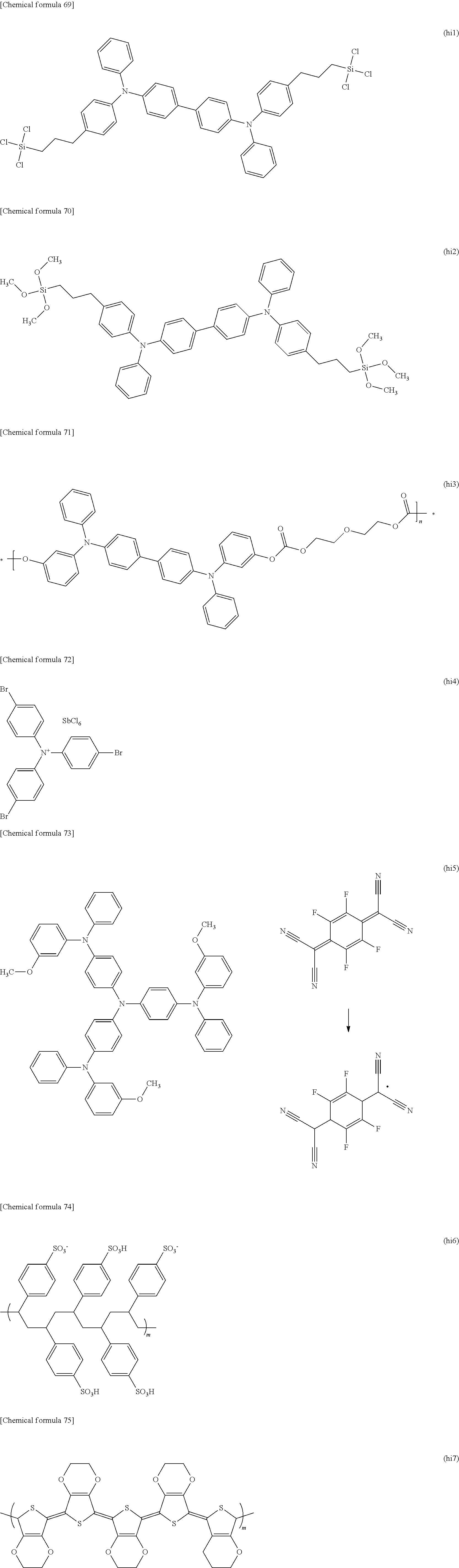


Claims (6)


Applications Claiming Priority (5)
| Application Number | Priority Date | Filing Date | Title |
|---|---|---|---|
| JP2015220371 | 2015-11-10 | ||
| JP2015-220371 | 2015-11-10 | ||
| JP2015242690 | 2015-12-11 | ||
| JP2015-242690 | 2015-12-11 | ||
| PCT/JP2016/083095 WO2017082246A1 (en) | 2015-11-10 | 2016-11-08 | Dicyanopyrazine compound, luminescent material, light transmitter using same, and production method for 2,5-dicyano-3,6-dihalogenopyrazine |
Related Parent Applications (1)
| Application Number | Title | Priority Date | Filing Date |
|---|---|---|---|
| PCT/JP2016/083095 A-371-Of-International WO2017082246A1 (en) | 2015-11-10 | 2016-11-08 | Dicyanopyrazine compound, luminescent material, light transmitter using same, and production method for 2,5-dicyano-3,6-dihalogenopyrazine |
Related Child Applications (2)
| Application Number | Title | Priority Date | Filing Date |
|---|---|---|---|
| US16/260,725 Division US10522763B2 (en) | 2015-11-10 | 2019-01-29 | Dicyanopyrazine compound, luminescent material, luminescence device using the same, and method for producing 2,5-dicyano-3,6-dihalogenopyrazine |
| US16/260,652 Division US10497878B2 (en) | 2015-11-10 | 2019-01-29 | Dicyanopyrazine compound, luminescent material, luminescence device using the same, and method for producing 2,5-dicyano-3,6-dihalogenopyrazine |
Publications (2)
| Publication Number | Publication Date |
|---|---|
| US20180273513A1 US20180273513A1 (en) | 2018-09-27 |
| US10399960B2 true US10399960B2 (en) | 2019-09-03 |
Family
ID=58695639
Family Applications (3)
| Application Number | Title | Priority Date | Filing Date |
|---|---|---|---|
| US15/769,578 Active US10399960B2 (en) | 2015-11-10 | 2016-11-08 | Dicyanopyrazine compound, luminescent material, luminescence device using the same, and method for producing 2,5-dicyano-3,6-dihalogenopyrazine |
| US16/260,652 Active US10497878B2 (en) | 2015-11-10 | 2019-01-29 | Dicyanopyrazine compound, luminescent material, luminescence device using the same, and method for producing 2,5-dicyano-3,6-dihalogenopyrazine |
| US16/260,725 Active US10522763B2 (en) | 2015-11-10 | 2019-01-29 | Dicyanopyrazine compound, luminescent material, luminescence device using the same, and method for producing 2,5-dicyano-3,6-dihalogenopyrazine |
Family Applications After (2)
| Application Number | Title | Priority Date | Filing Date |
|---|---|---|---|
| US16/260,652 Active US10497878B2 (en) | 2015-11-10 | 2019-01-29 | Dicyanopyrazine compound, luminescent material, luminescence device using the same, and method for producing 2,5-dicyano-3,6-dihalogenopyrazine |
| US16/260,725 Active US10522763B2 (en) | 2015-11-10 | 2019-01-29 | Dicyanopyrazine compound, luminescent material, luminescence device using the same, and method for producing 2,5-dicyano-3,6-dihalogenopyrazine |
Country Status (7)
| Country | Link |
|---|---|
| US (3) | US10399960B2 (en) |
| EP (3) | EP3882236B1 (en) |
| JP (3) | JP6850453B2 (en) |
| KR (2) | KR102612136B1 (en) |
| CN (3) | CN111995591B (en) |
| TW (3) | TWI712590B (en) |
| WO (1) | WO2017082246A1 (en) |
Families Citing this family (11)
| Publication number | Priority date | Publication date | Assignee | Title |
|---|---|---|---|---|
| TWI659029B (en) | 2017-01-13 | 2019-05-11 | 國立大學法人九州大學 | Dicyano n-heterocyclic compound, light-emitting material and light-emitting element using the same |
| CN110366548A (en) * | 2017-02-24 | 2019-10-22 | 国立大学法人九州大学 | Compound, luminescent material and light-emitting component |
| CN109593086A (en) * | 2017-09-30 | 2019-04-09 | 北京鼎材科技有限公司 | A kind of new compound and the organic electroluminescence device using the compound |
| CN109599504B (en) * | 2017-09-30 | 2022-02-18 | 北京鼎材科技有限公司 | Novel compound and organic electroluminescent device using same |
| CN110551112A (en) * | 2018-05-31 | 2019-12-10 | 江苏三月光电科技有限公司 | Dicyano pyrazine-containing compound and application thereof in organic electroluminescent device |
| CN112955437A (en) * | 2018-11-05 | 2021-06-11 | 默克专利有限公司 | Compounds useful in organic electronic devices |
| CN109810806B (en) * | 2019-03-14 | 2021-08-10 | 普信氟硅新材料(衢州)有限公司 | Flame-retardant electronic cleaning agent and preparation method thereof |
| CN110240574B (en) * | 2019-06-24 | 2023-04-07 | 武汉华星光电半导体显示技术有限公司 | Electroluminescent material, preparation method of electroluminescent material and luminescent device |
| CN112599676B (en) * | 2020-09-29 | 2022-11-01 | 湖南大学 | Organic ammonium salt p-type dopant |
| WO2023286454A1 (en) * | 2021-07-12 | 2023-01-19 | 東洋紡株式会社 | Method for producing aromatic dihalogen compound |
| CN113816911B (en) * | 2021-11-24 | 2022-03-08 | 季华实验室 | Red light material with multiple light emitting units and preparation method and application thereof |
Citations (33)
| Publication number | Priority date | Publication date | Assignee | Title |
|---|---|---|---|---|
| JPS6084273A (en) | 1983-10-17 | 1985-05-13 | Chisso Corp | 2,3-dicyano-5-substituted pyrazine derivative |
| US4592857A (en) | 1983-08-22 | 1986-06-03 | Chisso Corporation | 2,3-dicyano-5-substituted pyrazines |
| JPS61241727A (en) | 1985-04-19 | 1986-10-28 | Canon Inc | Liquid crystal element |
| JPS6271A (en) | 1985-03-15 | 1987-01-06 | Canon Inc | Liquid crystal compound and liquid crystal composition |
| JPS6210183A (en) | 1985-07-05 | 1987-01-19 | Canon Inc | Liquid crystal device |
| WO1988001264A1 (en) | 1986-08-13 | 1988-02-25 | Nippon Soda Co., Ltd. | 2,3-diaminoacrylonitrile derivatives |
| JPS6377864A (en) | 1986-09-19 | 1988-04-08 | Canon Inc | Liquid crystal compound and liquid crystal composition |
| JPH01252295A (en) | 1988-03-31 | 1989-10-06 | Nippon Soda Co Ltd | Production of 2,3-dicyano-5,6-dicyanopurazine |
| JPH0222609A (en) | 1988-07-11 | 1990-01-25 | Sumitomo Electric Ind Ltd | Coated optical fiber |
| JPH0279307A (en) | 1988-09-15 | 1990-03-19 | Kunio Kanamori | Globe for candle |
| JPH02115874A (en) | 1988-10-26 | 1990-04-27 | Ricoh Co Ltd | Toner replenishing container |
| JPH032973A (en) | 1989-05-31 | 1991-01-09 | Hitachi Ltd | Retrieving process method for data base |
| JPH032971A (en) | 1989-05-30 | 1991-01-09 | Fuji Photo Film Co Ltd | Picture filing system |
| WO1991003469A1 (en) | 1989-08-31 | 1991-03-21 | Nippon Soda Co., Ltd. | 3,6-diamino-2,5-pyrazinedicarbonitrile and production thereof |
| JPH0532640A (en) | 1990-09-06 | 1993-02-09 | Nippon Soda Co Ltd | Cyanopyrazine derivative |
| JPH06100566A (en) | 1992-09-18 | 1994-04-12 | Eastern:Kk | Octakis@(3754/24)alkoxyphenyl)tetrapyrazinoporphyradine compounds and composition containing the same and capable of forming discotic liquid crystal phase |
| JPH09188876A (en) | 1995-09-13 | 1997-07-22 | Lucent Technol Inc | Electroluminescent element |
| JPH11138974A (en) | 1997-11-10 | 1999-05-25 | Nippon Soda Co Ltd | Ink for preventing forgery and toner for electrophotography |
| JP2001002661A (en) | 1999-06-22 | 2001-01-09 | Ricoh Co Ltd | Nitrile compound and its production |
| JP2001089460A (en) | 1999-09-20 | 2001-04-03 | Koei Chem Co Ltd | Production process for 2-aminobromopiperazines |
| JP2001261658A (en) | 2000-03-17 | 2001-09-26 | Mitsubishi Chemicals Corp | Dicyanopyrazine-based compound and organic electric field light-generating element by using the same |
| JP2006241124A (en) | 2005-03-07 | 2006-09-14 | Shinshu Univ | Discotic liquid crystal membrane |
| EP1749822A1 (en) | 2005-08-05 | 2007-02-07 | Hybrigenics S.A. | Novel cysteine protease inhibitors and their therapeutic applications |
| WO2007017758A2 (en) | 2005-08-05 | 2007-02-15 | Hybrigenics Sa | Novel cysteine protease inhibitors and their therapeutic applications |
| JP2007204443A (en) | 2006-02-03 | 2007-08-16 | Nippon Soda Co Ltd | Organic solid fluorescent substance |
| CN101514262A (en) | 2009-03-19 | 2009-08-26 | 大连理工大学 | Ethylene naphthalene and paradiazine dye and application thereof to dye-sensitized solar cells. |
| CN101723907A (en) | 2009-07-25 | 2010-06-09 | 大连理工大学 | O-dicyano-acenaphtho pyrazine compound and anti-tumor application thereof |
| WO2011055911A1 (en) | 2009-11-04 | 2011-05-12 | Rohm And Haas Electronic Materials Korea Ltd. | Novel organic electroluminescent compounds and organic electroluminescent device using the same |
| CN102634333A (en) | 2012-04-01 | 2012-08-15 | 大连理工常熟研究院有限公司 | High-sensitive-polarity fluorescent probe by taking acenaphtho-pyrazine as mother body and preparation method and application thereof |
| KR20140027030A (en) | 2012-08-23 | 2014-03-06 | (주)씨에스엘쏠라 | Organic light compound and organic light device using the same |
| CN104830320A (en) * | 2015-05-24 | 2015-08-12 | 吉林大学 | Phenanthreneopyrazine derivative luminescent material and application thereof in electroluminescent device |
| JP2015153864A (en) | 2014-02-13 | 2015-08-24 | 国立大学法人山形大学 | Organic film and organic electronic device |
| JP2015172166A (en) | 2014-03-12 | 2015-10-01 | 株式会社カネカ | Light emitting material and organic electroluminescence (el) element using the same |
Family Cites Families (18)
| Publication number | Priority date | Publication date | Assignee | Title |
|---|---|---|---|---|
| JPS5522609A (en) * | 1978-08-03 | 1980-02-18 | Kyowa Gas Chem Ind Co Ltd | New herbicide |
| JPS5579307A (en) * | 1978-12-11 | 1980-06-14 | Kyowa Gas Chem Ind Co Ltd | Novel herbicide of pyrazine compound |
| JPS55115874A (en) * | 1979-02-28 | 1980-09-06 | Kyowa Gas Chem Ind Co Ltd | Preparation of 2,3-dicyano-5-hydroxypyrazine derivative |
| JPS562973A (en) * | 1979-06-20 | 1981-01-13 | Kyowa Gas Chem Ind Co Ltd | Preparation of aminopyrazine derivative |
| JPS562971A (en) * | 1979-06-20 | 1981-01-13 | Kyowa Gas Chem Ind Co Ltd | Novel 2,3,-dicyanopyrazine derivative, its preparation, and herbicide comprising it as active ingredient |
| JPS6375909A (en) | 1986-09-19 | 1988-04-06 | Canon Inc | Position controller |
| JP3503403B2 (en) * | 1997-03-17 | 2004-03-08 | 東洋インキ製造株式会社 | Light emitting material for organic electroluminescent device and organic electroluminescent device using the same |
| US7902222B2 (en) * | 2007-11-21 | 2011-03-08 | Abbott Laboratories | Biaryl substituted azabicyclic alkane derivatives |
| KR20120063283A (en) * | 2010-12-07 | 2012-06-15 | 제일약품주식회사 | Novel pyrazolopyridine derivatives or pharmaceutically acceptable salts thereof, process for the preparation thereof and pharmaceutical composition comprising the same |
| JP5522609B2 (en) | 2010-12-22 | 2014-06-18 | 高圧ガス保安協会 | Gas shut-off device |
| US9048367B2 (en) | 2012-06-04 | 2015-06-02 | Brightek Optoelectronic Co., Ltd. | Multichip package structure for generating a symmetrical and uniform light-blending source |
| JP6100566B2 (en) | 2013-03-18 | 2017-03-22 | 日本金銭機械株式会社 | Game medal and its discrimination device |
| JP6362044B2 (en) | 2014-05-19 | 2018-07-25 | 国立大学法人 筑波大学 | Semiconductor device and manufacturing method thereof |
| CN104707247B (en) | 2015-03-16 | 2016-09-28 | 唐强 | A kind of multi-functional electric needle therapeutic instrument |
| JP7083247B2 (en) * | 2015-05-08 | 2022-06-10 | メルク パテント ゲゼルシャフト ミット ベシュレンクテル ハフツング | Luminescent material, luminescent thin film, organic electroluminescence element, display device and lighting device |
| JP6084273B1 (en) | 2015-11-18 | 2017-02-22 | 株式会社Pfu | Document imaging device |
| JP6210183B1 (en) | 2016-04-19 | 2017-10-11 | Jfeスチール株式会社 | Steel sheet, plated steel sheet, and manufacturing method thereof |
| CN109053696B (en) | 2018-09-19 | 2021-09-21 | 西安瑞联新材料股份有限公司 | Bipyrazine derivative and application thereof in organic photoelectric device |
-
2016
- 2016-11-08 EP EP21170330.1A patent/EP3882236B1/en active Active
- 2016-11-08 CN CN202010939992.XA patent/CN111995591B/en active Active
- 2016-11-08 JP JP2017550331A patent/JP6850453B2/en active Active
- 2016-11-08 EP EP16864207.2A patent/EP3375779B1/en active Active
- 2016-11-08 EP EP21170331.9A patent/EP3882243B1/en active Active
- 2016-11-08 CN CN202010940593.5A patent/CN111995589B/en active Active
- 2016-11-08 TW TW109110890A patent/TWI712590B/en active
- 2016-11-08 CN CN201680060940.7A patent/CN108137554B/en active Active
- 2016-11-08 TW TW109110889A patent/TWI708765B/en active
- 2016-11-08 KR KR1020187011000A patent/KR102612136B1/en active IP Right Grant
- 2016-11-08 TW TW105136273A patent/TWI697481B/en active
- 2016-11-08 WO PCT/JP2016/083095 patent/WO2017082246A1/en active Application Filing
- 2016-11-08 US US15/769,578 patent/US10399960B2/en active Active
- 2016-11-08 KR KR1020237020678A patent/KR20230093541A/en not_active Application Discontinuation
-
2019
- 2019-01-29 US US16/260,652 patent/US10497878B2/en active Active
- 2019-01-29 US US16/260,725 patent/US10522763B2/en active Active
-
2020
- 2020-10-23 JP JP2020178379A patent/JP6994724B2/en active Active
- 2020-10-23 JP JP2020178380A patent/JP6994725B2/en active Active
Patent Citations (36)
| Publication number | Priority date | Publication date | Assignee | Title |
|---|---|---|---|---|
| US4592857A (en) | 1983-08-22 | 1986-06-03 | Chisso Corporation | 2,3-dicyano-5-substituted pyrazines |
| JPS6084273A (en) | 1983-10-17 | 1985-05-13 | Chisso Corp | 2,3-dicyano-5-substituted pyrazine derivative |
| JPS6271A (en) | 1985-03-15 | 1987-01-06 | Canon Inc | Liquid crystal compound and liquid crystal composition |
| JPS61241727A (en) | 1985-04-19 | 1986-10-28 | Canon Inc | Liquid crystal element |
| JPS6210183A (en) | 1985-07-05 | 1987-01-19 | Canon Inc | Liquid crystal device |
| WO1988001264A1 (en) | 1986-08-13 | 1988-02-25 | Nippon Soda Co., Ltd. | 2,3-diaminoacrylonitrile derivatives |
| JPS6377864A (en) | 1986-09-19 | 1988-04-08 | Canon Inc | Liquid crystal compound and liquid crystal composition |
| JPH01252295A (en) | 1988-03-31 | 1989-10-06 | Nippon Soda Co Ltd | Production of 2,3-dicyano-5,6-dicyanopurazine |
| JPH0222609A (en) | 1988-07-11 | 1990-01-25 | Sumitomo Electric Ind Ltd | Coated optical fiber |
| JPH0279307A (en) | 1988-09-15 | 1990-03-19 | Kunio Kanamori | Globe for candle |
| JPH02115874A (en) | 1988-10-26 | 1990-04-27 | Ricoh Co Ltd | Toner replenishing container |
| JPH032971A (en) | 1989-05-30 | 1991-01-09 | Fuji Photo Film Co Ltd | Picture filing system |
| JPH032973A (en) | 1989-05-31 | 1991-01-09 | Hitachi Ltd | Retrieving process method for data base |
| WO1991003469A1 (en) | 1989-08-31 | 1991-03-21 | Nippon Soda Co., Ltd. | 3,6-diamino-2,5-pyrazinedicarbonitrile and production thereof |
| US5294711A (en) | 1989-08-31 | 1994-03-15 | Nippon Soda Co., Ltd. | 3,6-diamino-2,5-pyrazinedicarbonitrile |
| JPH0532640A (en) | 1990-09-06 | 1993-02-09 | Nippon Soda Co Ltd | Cyanopyrazine derivative |
| JPH06100566A (en) | 1992-09-18 | 1994-04-12 | Eastern:Kk | Octakis@(3754/24)alkoxyphenyl)tetrapyrazinoporphyradine compounds and composition containing the same and capable of forming discotic liquid crystal phase |
| US5904994A (en) | 1995-09-13 | 1999-05-18 | Lucent Technologies Inc. | Blue-emitting materials and electroluminescent devices containing these materials |
| JPH09188876A (en) | 1995-09-13 | 1997-07-22 | Lucent Technol Inc | Electroluminescent element |
| JPH11138974A (en) | 1997-11-10 | 1999-05-25 | Nippon Soda Co Ltd | Ink for preventing forgery and toner for electrophotography |
| JP2001002661A (en) | 1999-06-22 | 2001-01-09 | Ricoh Co Ltd | Nitrile compound and its production |
| JP2001089460A (en) | 1999-09-20 | 2001-04-03 | Koei Chem Co Ltd | Production process for 2-aminobromopiperazines |
| JP2001261658A (en) | 2000-03-17 | 2001-09-26 | Mitsubishi Chemicals Corp | Dicyanopyrazine-based compound and organic electric field light-generating element by using the same |
| JP2006241124A (en) | 2005-03-07 | 2006-09-14 | Shinshu Univ | Discotic liquid crystal membrane |
| JP2009503052A (en) | 2005-08-05 | 2009-01-29 | ヒブリジェニクス・エスアー | Novel cysteine protease inhibitors and their therapeutic applications |
| EP1749822A1 (en) | 2005-08-05 | 2007-02-07 | Hybrigenics S.A. | Novel cysteine protease inhibitors and their therapeutic applications |
| WO2007017758A2 (en) | 2005-08-05 | 2007-02-15 | Hybrigenics Sa | Novel cysteine protease inhibitors and their therapeutic applications |
| JP2007204443A (en) | 2006-02-03 | 2007-08-16 | Nippon Soda Co Ltd | Organic solid fluorescent substance |
| CN101514262A (en) | 2009-03-19 | 2009-08-26 | 大连理工大学 | Ethylene naphthalene and paradiazine dye and application thereof to dye-sensitized solar cells. |
| CN101723907A (en) | 2009-07-25 | 2010-06-09 | 大连理工大学 | O-dicyano-acenaphtho pyrazine compound and anti-tumor application thereof |
| WO2011055911A1 (en) | 2009-11-04 | 2011-05-12 | Rohm And Haas Electronic Materials Korea Ltd. | Novel organic electroluminescent compounds and organic electroluminescent device using the same |
| CN102634333A (en) | 2012-04-01 | 2012-08-15 | 大连理工常熟研究院有限公司 | High-sensitive-polarity fluorescent probe by taking acenaphtho-pyrazine as mother body and preparation method and application thereof |
| KR20140027030A (en) | 2012-08-23 | 2014-03-06 | (주)씨에스엘쏠라 | Organic light compound and organic light device using the same |
| JP2015153864A (en) | 2014-02-13 | 2015-08-24 | 国立大学法人山形大学 | Organic film and organic electronic device |
| JP2015172166A (en) | 2014-03-12 | 2015-10-01 | 株式会社カネカ | Light emitting material and organic electroluminescence (el) element using the same |
| CN104830320A (en) * | 2015-05-24 | 2015-08-12 | 吉林大学 | Phenanthreneopyrazine derivative luminescent material and application thereof in electroluminescent device |
Non-Patent Citations (7)
| Title |
|---|
| Begland et al., J. Org. Chem., vol. 39, No. 9, 1235 (1974). |
| Chew et al: "Photoluminescence and electroluminescence of a novel green-yellow emitting material-5,6-Bis-[4-(naphthalene-1-yl-phenyl-amino)-phenyl]-pyrazine-2,3-dicarbonitrile", Journal of Luminescence, Elsevier BV North-Holland, Nl, vol. 124, No. 2, 29, Nov. 2006, pp. 221-227. |
| Feb. 14, 2017 International Search Report issued in International Application No. PCT/JP2016/083095. |
| Mar. 20, 2019 Search Report issued in European Patent Application No. 16864207.2. |
| N. Sato et al., "Synthesis of 3,6-Dibromopyrazine-2,5-dicarbonitrile[1]," J. Heterocyclic. Chem., vol. 49, 675 (2012). |
| N. Sato, Journal of Heterocyclic Chemistry, vol. 26, 817 (1989). |
| Wang et al: "Highly Efficient Near-Infrared Delayed Fluorescence Organic Light Emitting Diodes Using a Phenanthrene-Based Charge-Transfer Compound", Angewandte Chemie International Edition, vol. 54, No. 44, 26, Oct. 25, 2015, pp. 13068-13072. |
Also Published As
Similar Documents
| Publication | Publication Date | Title |
|---|---|---|
| US10522763B2 (en) | Dicyanopyrazine compound, luminescent material, luminescence device using the same, and method for producing 2,5-dicyano-3,6-dihalogenopyrazine | |
| US20210332032A1 (en) | Benzonitrile derivative, light-emitting material, and light-emitting element using same | |
| US11279680B2 (en) | Dicyano N-heterocyclic compound, light-emitting material, and light-emitting element in which same is used | |
| EP3985081A1 (en) | Isophthalonitrile compounds, luminescent material, and luminescent element including same | |
| JP2018177647A (en) | Dicyano pentahelicene compound, light emitting material, and light emitting element prepared therewith | |
| KR20230006802A (en) | Boron-containing compound, light-emitting material, and light-emitting device using the same |
Legal Events
| Date | Code | Title | Description |
|---|---|---|---|
| AS | Assignment |
Owner name: KYUSHU UNIVERSITY, NATIONAL UNIVERSITY CORPORATION Free format text: ASSIGNMENT OF ASSIGNORS INTEREST;ASSIGNORS:YASUDA, TAKUMA;PARK, IN SEOB;YANG, YU SEOK;AND OTHERS;REEL/FRAME:045590/0622 Effective date: 20180409 Owner name: NIPPON SODA CO., LTD., JAPAN Free format text: ASSIGNMENT OF ASSIGNORS INTEREST;ASSIGNORS:YASUDA, TAKUMA;PARK, IN SEOB;YANG, YU SEOK;AND OTHERS;REEL/FRAME:045590/0622 Effective date: 20180409 |
|
| FEPP | Fee payment procedure |
Free format text: ENTITY STATUS SET TO UNDISCOUNTED (ORIGINAL EVENT CODE: BIG.); ENTITY STATUS OF PATENT OWNER: LARGE ENTITY |
|
| STPP | Information on status: patent application and granting procedure in general |
Free format text: RESPONSE TO NON-FINAL OFFICE ACTION ENTERED AND FORWARDED TO EXAMINER |
|
| STPP | Information on status: patent application and granting procedure in general |
Free format text: NOTICE OF ALLOWANCE MAILED -- APPLICATION RECEIVED IN OFFICE OF PUBLICATIONS |
|
| STPP | Information on status: patent application and granting procedure in general |
Free format text: AWAITING TC RESP., ISSUE FEE NOT PAID |
|
| STPP | Information on status: patent application and granting procedure in general |
Free format text: PUBLICATIONS -- ISSUE FEE PAYMENT VERIFIED |
|
| STCF | Information on status: patent grant |
Free format text: PATENTED CASE |
|
| MAFP | Maintenance fee payment |
Free format text: PAYMENT OF MAINTENANCE FEE, 4TH YEAR, LARGE ENTITY (ORIGINAL EVENT CODE: M1551); ENTITY STATUS OF PATENT OWNER: LARGE ENTITY Year of fee payment: 4 |