US10375853B2 - Electronic device with cooling fan - Google Patents
Electronic device with cooling fan Download PDFInfo
- Publication number
- US10375853B2 US10375853B2 US15/682,291 US201715682291A US10375853B2 US 10375853 B2 US10375853 B2 US 10375853B2 US 201715682291 A US201715682291 A US 201715682291A US 10375853 B2 US10375853 B2 US 10375853B2
- Authority
- US
- United States
- Prior art keywords
- fan
- inlet opening
- impeller
- enclosure
- external protrusion
- Prior art date
- Legal status (The legal status is an assumption and is not a legal conclusion. Google has not performed a legal analysis and makes no representation as to the accuracy of the status listed.)
- Active
Links
Images


Classifications
-
- H—ELECTRICITY
- H05—ELECTRIC TECHNIQUES NOT OTHERWISE PROVIDED FOR
- H05K—PRINTED CIRCUITS; CASINGS OR CONSTRUCTIONAL DETAILS OF ELECTRIC APPARATUS; MANUFACTURE OF ASSEMBLAGES OF ELECTRICAL COMPONENTS
- H05K7/00—Constructional details common to different types of electric apparatus
- H05K7/20—Modifications to facilitate cooling, ventilating, or heating
- H05K7/20009—Modifications to facilitate cooling, ventilating, or heating using a gaseous coolant in electronic enclosures
- H05K7/20136—Forced ventilation, e.g. by fans
- H05K7/20145—Means for directing air flow, e.g. ducts, deflectors, plenum or guides
-
- F—MECHANICAL ENGINEERING; LIGHTING; HEATING; WEAPONS; BLASTING
- F04—POSITIVE - DISPLACEMENT MACHINES FOR LIQUIDS; PUMPS FOR LIQUIDS OR ELASTIC FLUIDS
- F04D—NON-POSITIVE-DISPLACEMENT PUMPS
- F04D17/00—Radial-flow pumps, e.g. centrifugal pumps; Helico-centrifugal pumps
- F04D17/08—Centrifugal pumps
- F04D17/16—Centrifugal pumps for displacing without appreciable compression
-
- F—MECHANICAL ENGINEERING; LIGHTING; HEATING; WEAPONS; BLASTING
- F04—POSITIVE - DISPLACEMENT MACHINES FOR LIQUIDS; PUMPS FOR LIQUIDS OR ELASTIC FLUIDS
- F04D—NON-POSITIVE-DISPLACEMENT PUMPS
- F04D25/00—Pumping installations or systems
- F04D25/02—Units comprising pumps and their driving means
- F04D25/06—Units comprising pumps and their driving means the pump being electrically driven
- F04D25/0606—Units comprising pumps and their driving means the pump being electrically driven the electric motor being specially adapted for integration in the pump
- F04D25/0613—Units comprising pumps and their driving means the pump being electrically driven the electric motor being specially adapted for integration in the pump the electric motor being of the inside-out type, i.e. the rotor is arranged radially outside a central stator
-
- F—MECHANICAL ENGINEERING; LIGHTING; HEATING; WEAPONS; BLASTING
- F04—POSITIVE - DISPLACEMENT MACHINES FOR LIQUIDS; PUMPS FOR LIQUIDS OR ELASTIC FLUIDS
- F04D—NON-POSITIVE-DISPLACEMENT PUMPS
- F04D29/00—Details, component parts, or accessories
- F04D29/40—Casings; Connections of working fluid
- F04D29/42—Casings; Connections of working fluid for radial or helico-centrifugal pumps
- F04D29/44—Fluid-guiding means, e.g. diffusers
- F04D29/441—Fluid-guiding means, e.g. diffusers especially adapted for elastic fluid pumps
-
- G—PHYSICS
- G06—COMPUTING; CALCULATING OR COUNTING
- G06F—ELECTRIC DIGITAL DATA PROCESSING
- G06F1/00—Details not covered by groups G06F3/00 - G06F13/00 and G06F21/00
- G06F1/16—Constructional details or arrangements
- G06F1/1613—Constructional details or arrangements for portable computers
- G06F1/1633—Constructional details or arrangements of portable computers not specific to the type of enclosures covered by groups G06F1/1615 - G06F1/1626
- G06F1/1656—Details related to functional adaptations of the enclosure, e.g. to provide protection against EMI, shock, water, or to host detachable peripherals like a mouse or removable expansions units like PCMCIA cards, or to provide access to internal components for maintenance or to removable storage supports like CDs or DVDs, or to mechanically mount accessories
- G06F1/1658—Details related to functional adaptations of the enclosure, e.g. to provide protection against EMI, shock, water, or to host detachable peripherals like a mouse or removable expansions units like PCMCIA cards, or to provide access to internal components for maintenance or to removable storage supports like CDs or DVDs, or to mechanically mount accessories related to the mounting of internal components, e.g. disc drive or any other functional module
-
- G—PHYSICS
- G06—COMPUTING; CALCULATING OR COUNTING
- G06F—ELECTRIC DIGITAL DATA PROCESSING
- G06F1/00—Details not covered by groups G06F3/00 - G06F13/00 and G06F21/00
- G06F1/16—Constructional details or arrangements
- G06F1/1613—Constructional details or arrangements for portable computers
- G06F1/1633—Constructional details or arrangements of portable computers not specific to the type of enclosures covered by groups G06F1/1615 - G06F1/1626
- G06F1/1662—Details related to the integrated keyboard
-
- G—PHYSICS
- G06—COMPUTING; CALCULATING OR COUNTING
- G06F—ELECTRIC DIGITAL DATA PROCESSING
- G06F1/00—Details not covered by groups G06F3/00 - G06F13/00 and G06F21/00
- G06F1/16—Constructional details or arrangements
- G06F1/20—Cooling means
-
- G—PHYSICS
- G06—COMPUTING; CALCULATING OR COUNTING
- G06F—ELECTRIC DIGITAL DATA PROCESSING
- G06F1/00—Details not covered by groups G06F3/00 - G06F13/00 and G06F21/00
- G06F1/16—Constructional details or arrangements
- G06F1/20—Cooling means
- G06F1/203—Cooling means for portable computers, e.g. for laptops
-
- H—ELECTRICITY
- H01—ELECTRIC ELEMENTS
- H01L—SEMICONDUCTOR DEVICES NOT COVERED BY CLASS H10
- H01L23/00—Details of semiconductor or other solid state devices
- H01L23/34—Arrangements for cooling, heating, ventilating or temperature compensation ; Temperature sensing arrangements
- H01L23/40—Mountings or securing means for detachable cooling or heating arrangements ; fixed by friction, plugs or springs
- H01L23/4006—Mountings or securing means for detachable cooling or heating arrangements ; fixed by friction, plugs or springs with bolts or screws
-
- H—ELECTRICITY
- H01—ELECTRIC ELEMENTS
- H01L—SEMICONDUCTOR DEVICES NOT COVERED BY CLASS H10
- H01L23/00—Details of semiconductor or other solid state devices
- H01L23/34—Arrangements for cooling, heating, ventilating or temperature compensation ; Temperature sensing arrangements
- H01L23/46—Arrangements for cooling, heating, ventilating or temperature compensation ; Temperature sensing arrangements involving the transfer of heat by flowing fluids
- H01L23/467—Arrangements for cooling, heating, ventilating or temperature compensation ; Temperature sensing arrangements involving the transfer of heat by flowing fluids by flowing gases, e.g. air
Definitions
- This relates generally to electronic devices, and more specifically, to electronic devices with internal cooling fans.
- Electronic devices contain components that produce heat during normal operation. Fans, heat sinks, and/or other heat management components are used to reduce heat. But increasingly faster and more powerful chips and integrated circuitry can generate more heat than previous generations of electronics. Placement of these components into smaller overall volumes can create new challenges.
- a fan assembly is attached to a keyboard assembly of the electronic device.
- the fan assembly includes an impeller at least partially inside a fan enclosure.
- the fan enclosure has, on a surface, an inlet opening and an external protrusion.
- the electronic device further includes a bottom case.
- the fan assembly is positioned between the keyboard assembly and the bottom case and oriented such that the inlet opening and the external protrusion face the bottom case.
- the external protrusion maintains a passage between the fan enclosure and the bottom case that allows air to enter the inlet opening.
- FIG. 1A illustrates a front perspective view of an electronic device, according to various examples.
- FIG. 1B illustrates a partial plan view of an interior region of a base portion of an electronic device with a cooling fan, according to various examples.
- FIG. 1C illustrates a cross-sectional view of a portion of an electronic device with an internal cooling fan, according to various examples.
- FIGS. 2A-2B illustrate top perspective views of a cooling fan of an electronic device, according to various examples.
- FIG. 2C illustrates a bottom perspective view of a cooling fan of an electronic device, according to various examples.
- FIG. 2D illustrates a cross-sectional view of a cooling fan of an electronic device, according to various examples.
- FIG. 3 illustrates a magnified perspective view of an external protrusion on the surface of a cooling fan, according to various examples.
- FIG. 4 illustrates simulated airflow around an external protrusion of a cooling fan, where the external protrusion has a teardrop-shaped cross-section, according to various examples.
- FIG. 5 illustrates simulated airflow around an external protrusion of a cooling fan, where the external protrusion has a circular cross-section, according to various examples.
- FIG. 6 illustrates a cross-sectional view of a diffuser portion of a cooling fan, according to various examples.
- FIG. 7 illustrates a cover portion of a fan enclosure of a cooling fan, according to various examples.
- FIG. 8 illustrates a base plate of a fan enclosure of a cooling fan, according to various examples.
- FIGS. 9A-9B illustrate cross-sectional perspective views of a cover portion of a fan enclosure of a cooling fan, according to various examples.
- FIG. 10 illustrates a cross-sectional view of an electronic device where the motherboard is attached to a cover portion of a fan enclosure of a cooling fan, according to various examples.
- FIG. 11 illustrates a cross-sectional view of an electronic device where the motherboard is attached to a base plate of a fan enclosure of a cooling fan, according to various examples.
- FIG. 12A illustrates a top-down view of a cooling fan attached to a base layer of a keyboard assembly, according to various examples.
- FIG. 12B illustrates a top-down view of a base plate of a fan enclosure of a cooling fan attached to a base layer of a keyboard assembly, according to various examples.
- FIG. 13 illustrates a top-down view of a portion of an electronic device where cooling fans are attached to a keyboard assembly that has one of several possible configurations, according to various examples.
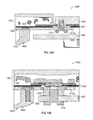
- FIG. 14A illustrates a cross-sectional view of a portion of an electronic device where a cooling fan is attached to a keyboard assembly via a base plate of the cooling fan, according to various examples.
- FIG. 14B illustrates a cross-sectional view of a portion of an electronic device where a motherboard is attached a base plate of a cooling fan, according to various examples.
- Electronic devices contain components that produce heat during normal operation. As such, fans, heat sinks, and other heat diversion components are used to manage operating temperatures in some electronic devices. Heat-producing components generate heat at increasing levels, and ongoing consumer demands require that devices become smaller and thinner, such that fans and other components need to be smaller and more efficient.
- integrating fans into smaller or thinner devices can result in the fans being more susceptible to damage during user handling events.
- fans that are integrated into smaller or thinner devices can have components that are positioned very close together. This increases the likelihood that stationary and moving components in the fan rub against each other and cause damage or unwanted noise during user handling events.
- force exerted on the keyboard or external case of an electronic device can transfer to the fan and cause stationary components of the fan (e.g., the fan enclosure) to rub against moving components of the fan (e.g., the impeller).
- stationary components of the fan e.g., the fan enclosure
- moving components of the fan e.g., the impeller
- fans that are integrated into smaller or thinner devices can be more susceptible to localized obstruction to airflow, which can result in higher friction losses, more turbulent airflow, vortex shedding, and increased aeroacoustic noise.
- a fan assembly is attached to a keyboard assembly of the electronic device.
- the fan assembly includes an impeller at least partially inside a fan enclosure.
- the fan enclosure has, on a surface, an inlet opening and an external protrusion.
- the electronic device further includes a bottom case.
- the fan assembly is positioned between the keyboard assembly and the bottom case and oriented such that the inlet opening and the external protrusion face the bottom case.
- the external protrusion maintains clearance between the fan assembly and the bottom case during user handling events to ensure proper fan operation.
- FIG. 1A illustrates a front perspective view of an exemplary electronic device.
- an electronic device suitable for use with the disclosed cooling fan can include a desktop computing device with a built-in display, a portable computing device, or a video-streaming device, for example.
- electronic device 100 can be a consumer electronic device such as a laptop computer.
- electronic device 100 includes display housing 102 coupled with base portion 104 , allowing display housing 102 to pivot with respect to base portion 104 .
- display housing 102 and base portion 104 are formed from a metal, such as aluminum.
- display housing 102 and base portion 104 are formed from plastic.
- Display housing 102 includes display panel 106 designed to provide visual content.
- Base portion 104 includes top case 112 coupled with a bottom case (e.g., bottom case 122 shown in FIG. 1C ). Top case 112 and the bottom case define a space designed to receive several components of electronic device 100 , such as processor circuits, memory circuits, and one or more battery modules. Also, base portion 104 includes several components allowing a user to input one or more controls to the electronic device 100 , such as touch pad 116 and keyboard assembly 118 .
- base portion 104 can include an internal cooling fan.
- FIG. 1B illustrates a partial plan view of an interior region of base portion 104 of electronic device 100 , according to various examples. The bottom case of base portion 104 is removed to show cooling fan 200 disposed within base portion 104 . In the perspective view shown in FIG. 1B , keys 124 of keyboard assembly 118 are oriented into the plane of the drawing and cooling fan 200 is positioned over the bottom surface of keyboard assembly 118 .
- Cooling fan 200 includes fan enclosure 202 and impeller 206 disposed at least partially inside fan enclosure 202 .
- Fan enclosure 202 forms an exterior surface for the fan and defines inlet opening 212 and outlet opening 210 of cooling fan 200 .
- Heat from at least some of the several components of electronic device 100 can be transported via a heat pipe (not shown) to cooling fins 120 that are disposed adjacent to outlet opening 210 .
- a motor (not shown) of cooling fan 200 is configured to rotate impeller 206 to draw air into inlet opening 212 and expel air through outlet opening 210 into cooling fins 120 , thereby removing heat from cooling fins 120 and cooling electronic device 100 .
- FIG. 1C illustrates a cross-sectional view of a portion of electronic device 100 with cooling fan 200 , according to various examples.
- FIG. 1C is a cross-sectional view of electronic device 100 taken along the portion indicated by dotted line 123 on FIG. 1B .
- Bottom case 122 of base portion 104 is included in the depiction of electronic device 100 in FIG. 1C .
- keyboard assembly 118 and cooling fan 200 are disposed at least partially between top case 112 and bottom case 122 of bottom portion 104 .
- Keyboard assembly 118 in some examples, is attached to top case 112 .
- Cooling fan 200 is attached to base layer 126 of keyboard assembly 118 and is oriented such that inlet opening 212 and external protrusion 214 face bottom case 122 .
- Cooling fan 200 does not directly contact bottom case 122 .
- external protrusion 214 protrudes from outer surface 204 of fan enclosure 202 .
- External protrusion 214 is separated from bottom case 122 by gap 130 and thus does not directly contact bottom case 122 .
- height 134 of gap 130 is approximately 0.8-1.2 mm. In a specific example, height 134 of gap 130 is approximately 1.0 mm.
- External protrusion 214 can serve to increase the amount of force that cooling fan 200 can sustain from user handling of electronic device 100 before damage is incurred.
- top case 112 and/or bottom case 122 can experience compressive forces that cause bottom case 122 to translate toward cooling fan 200 or vice versa.
- external protrusion 214 resists inner surface 132 of bottom case 122 from directly contacting impeller 206 . Direct contact of bottom case 122 with impeller 206 is undesirable as it can interfere with the rotation of impeller 206 , which can generate undesirable frictional noise and also cause damage to cooling fan 200 .
- External protrusion 214 maintains passage 128 between fan enclosure 202 and bottom case 122 that allows air to enter the inlet opening 212 .
- inner surface 132 of bottom case 122 can directly contact external protrusion 214 without inner surface 132 of bottom case 122 directly contacting impeller 206 or portion 216 of fan enclosure 202 .
- External protrusion 214 thus increases the amount of force that top case 112 and/or bottom case 122 can sustain before bottom case 122 interferes with the rotation of impeller 206 .
- external protrusion 214 enables cooling fan 200 to be positioned closer to bottom case 122 because external protrusion 214 serves to limit the motion of cooling fan 200 during a shock event (e.g., electronic device is dropped and impacts a surface). This is desirable because reducing the motion of cooling fan 200 reduces the amount of strain that cooling fan 200 experiences.
- height 136 of passage 128 between portion 216 and bottom case 122 is approximately 1.8-2.0 mm.
- distance 138 between the hub of impeller 206 and bottom case 122 is approximately 1.5-1.8 mm. Additional details regarding external protrusion 214 are described below with reference to FIGS. 2A-D and FIGS. 3-5 .
- cooling fan 200 is positioned between keyboard assembly 118 and bottom case 122 . Cooling fan 200 is attached to base layer 126 of keyboard assembly 118 and keyboard assembly 118 is attached to top case 112 , in some examples.
- keyboard assembly 118 includes keys 124 , support mechanisms 110 , and electronics package 108 . Each key 124 is supported by support mechanism 110 that translates key 124 vertically in response to a downward force on key 124 during a keystroke event.
- each electronics package 108 includes a switch attached to a flexible printed circuit board. The switch of electronics package 108 biases key 124 to be in its natural, non-depressed position.
- each electronics package 108 further includes a light source (e.g., light-emitting diode) for backlighting the respective key 124 .
- Support mechanisms 110 and electronics packages 108 are attached to base layer 126 of keyboard assembly 118 .
- Base layer 126 can provide the platform for the components contained within the keyboard assembly.
- base layer 126 includes openings (e.g., openings 1206 shown in FIGS. 12A-B ) that extend from a top surface to a bottom surface of base layer 126 .
- Base layer 126 includes one or more layers.
- base layer 126 includes one or more of a feature plate, a circuit board, an illumination panel, or a sensor membrane.
- base layer 126 can include other layers necessary for the function of keyboard assembly 118 .
- base layer 126 includes an electromagnetic inference (EMI) shielding layer for shielding the electronic components of keyboard assembly 118 (e.g., electronics packages 108 or the circuit board of base layer 126 ) from EMI generated by components within bottom portion 104 .
- EMI electromagnetic inference
- the EMI shielding layer also shields EMI generated by components within bottom portion 104 , thereby reducing the amount of EMI escaping into free-space.
- the EMI shielding layer in some examples, is the bottommost layer of base layer 126 adjacent to cooling fan 200 .
- the EMI shielding layer includes a metal film that extends across base layer 126 .
- the EMI shielding layer can be grounded.
- the EMI shielding layer includes an aluminized Mylar layer.
- cooling fan 200 is directly attached to keyboard assembly 118 .
- cooling fan 200 is directly attached to the bottom surface of keyboard assembly 118 such that a majority of an outer surface of back wall 232 is positioned substantially flush against the bottom surface of keyboard assembly 118 .
- the majority of the outer surface of back wall 232 is thus in direct contact with the bottom surface of keyboard assembly 118 .
- the bottom surface of keyboard assembly 118 corresponds to the bottom surface of base layer 126 .
- the bottom surface of base layer 126 is oriented toward bottom case 122 and away from keys 124 .
- Back wall 232 of fan enclosure 202 is disposed on a side of the fan enclosure 202 opposite of inlet opening 212 . Back wall 232 is thus oriented toward top case 112 .
- Positioning back wall 232 of fan enclosure 202 directly against the bottom surface of keyboard assembly 118 can be desirable to reduce the vertical space occupied by the fan, which enables a thinner base portion 104 of electronic device 100 . Additionally, the amount of noise generated during operation of cooling fan 200 is reduced. Specifically, when back wall 232 is positioned directly against base layer 126 of keyboard assembly 118 , the vibration of back wall 232 caused by the rotation of the motor and impeller 206 is dampened by base layer 126 and other components of keyboard assembly 118 . This reduces the amplitude of vibration generated by cooling fan 200 .
- cooling fan 200 were attached to keyboard assembly 118 with spacers that maintain a gap (e.g., greater than 0.2 mm gap) between the outer surface of back wall 232 and the bottom surface of keyboard assembly 118 , back wall 232 is less supported and various vibration modes can develop on back wall 232 during operation of cooling fan 200 . This could result in increased vibrational noise from cooling fan 200 . Additional aspects regarding positioning back wall 232 of cooling fan 200 against the bottom surface of keyboard assembly 118 are described below with reference to FIGS. 12A-B .
- FIGS. 2A-D illustrate top perspective views of cooling fan 200 , according to various examples.
- FIG. 2C illustrates a bottom perspective view of cooling fan 200 , according to various examples.
- FIG. 2D illustrates a cross-section view of cooling fan 200 with the motor and bearing not shown, according to various examples. The cross-sectional view of cooling fan 200 in FIG. 2D is taken along dotted line 240 shown in FIG. 2B .
- Cooling fan 200 can also be referred to as a fan assembly.
- cooling fan 200 is a centrifugal fan designed to draw air through inlet opening 212 into the center of the fan and drive the air radially outward from the center of the fan and out through outlet opening 210 of the fan.
- Cooling fan 200 includes fan enclosure 202 that forms an exterior surface for the fan and impeller 206 that is disposed at least partially inside fan enclosure 202 .
- Fan enclosure 202 also defines a fan cavity that at least partially houses impeller 206 .
- Impeller 206 includes a plurality of blades 222 positioned around hub 238 . A portion of impeller 206 extends out from the interior of fan enclosure 202 through inlet opening 212 . Specifically, as shown in FIGS.
- hub 238 of impeller 206 extends at least partially out through inlet opening 212 .
- the impeller can be entirely disposed within the fan enclosure such that the hub of the impeller does not extend beyond the plane of inlet opening 212 .
- cooling fan 200 is a centrifugal fan, it should be recognized that at least some of the features of cooling fan 200 described herein are applicable to other mechanical fan configurations.
- Cooling fan 200 further includes a motor and bearing (not shown) disposed within fan hub 238 that rotates impeller 206 with respect to rotation axis 226 that is aligned to the center of hub 238 .
- Power is transmitted to the motor via flexible printed circuit (FPC) 236 of cooling fan 200 (shown in FIG. 2C ).
- FPC flexible printed circuit
- the motor emits a back electromotive force (EMF) signal that is transmitted through FPC 236 to a driver circuit separate from cooling fan 200 .
- FPC 236 is thus configured to transmit a back EMF signal generated by the motor of cooling fan 200 to the driver circuit.
- the back EMF signal indicates the rotational speed of the motor.
- One end of FPC 236 is attached to the motor within fan enclosure 202 .
- FPC 236 extends out from fan enclosure 202 through opening 237 (e.g., similar or identical to opening 802 shown in FIG. 8 ) on back wall 232 .
- An external portion of FPC 236 is positioned along the outer surface of back wall 232 of fan enclosure 202 .
- Fan enclosure 202 includes front wall 224 disposed on one side of impeller 206 and back wall 232 disposed on an opposite side of impeller 206 .
- Fan housing 202 also includes sidewalls 234 that surround most of the perimeter of impeller 206 .
- Sidewalls 234 couple back wall 232 to front wall 224 .
- front wall 224 and side wall 234 are formed integrally as one part.
- Front wall 224 defines inlet opening 212 for allowing air to enter into fan enclosure 202 of cooling fan 200 .
- a second inlet opening for allowing air into the fan enclosure can be included on the back wall of the fan enclosure.
- Fan enclosure 202 further includes diffuser portion 230 disposed on one side of cooling fan 200 .
- cooling fan 200 air is directed through a diffuser channel (e.g., diffuser channel 606 shown in FIG. 6 ) of diffuser portion 230 and expelled out from outlet opening 210 .
- Outlet opening 210 is disposed at the end of the diffuser channel and is oriented approximately perpendicularly to inlet opening 212 . It should be recognized that various alternative air inlet and air outlet arrangements may also be used.
- fan enclosure 202 The dimensions of fan enclosure 202 are suitably designed to address the challenges discussed above.
- the vertical profile of fan enclosure is small to enable a thinner and sleeker electronic device.
- distance 248 from outer surface 204 of front wall 224 adjacent to blade 222 to outer surface of back wall 232 is approximately 4.0-4.4 mm
- distance 252 from outer surface 204 of front wall 224 at outlet opening 210 to outer surface of back wall 232 at outlet opening is approximately 5.0-6.0 mm
- distance 250 from end surface of external protrusion 214 to outer surface of back wall 232 is approximately 5.0-6.0 mm.
- fan enclosure 202 includes external protrusion 214 that protrudes from outer surface 204 of fan enclosure 202 .
- external protrusion 214 is approximately perpendicular to outer surface 204 of fan enclosure 202 .
- External protrusion 214 is configured to resist bottom case 122 from directly contacting impeller 206 or outer surface 204 of fan enclosure 202 , thereby increasing the amount of force that cooling fan 200 can sustain during user handling events before damage or unwanted rubbing noise is incurred.
- passage 128 is maintained between outer surface 204 of fan enclosure 202 and bottom case 122 and allows air to enter inlet opening 212 .
- external protrusion 214 protrudes from outer surface 204 , external protrusion can partially obstruct airflow toward inlet opening 212 . Excessive obstruction to the airflow can cause the formation of turbulent airflow upstream of inlet opening 212 .
- the turbulent airflow can be intensified by impeller 206 after entering inlet opening and can cause airflow exiting outlet opening 210 to become even more turbulent. Turbulent airflow entering or exiting cooling fan 200 is undesirable as it produces undesirable aeroacoustic noise.
- external protrusion 214 can be positioned away from areas where airflow is the strongest.
- external protrusion 214 can be positioned on outer surface 204 where airflow toward inlet opening 212 is minimal. In the present example, airflow toward inlet opening 212 is the strongest near diffuser portion 230 and near inlet opening 212 . Thus, as shown in FIGS. 2A-B , external protrusion 214 is positioned proximate to a side opposite of diffuser portion 230 such that inlet opening 212 is positioned between external protrusion 214 and diffuser portion 230 . Additionally, external protrusion 214 is positioned proximate to sidewall 234 and thus away from inlet opening 212 where airflow is stronger. Specifically, external protrusion 214 is positioned closer to sidewall 234 of fan enclosure 202 than inlet opening 212 .
- external protrusion 214 directly overlaps with a portion of sidewall 234 .
- Positioning external protrusion 214 at the perimeter of outer surface 204 and above sidewall 234 can be desirable for providing greater support and strength to external protrusion 214 .
- a force applied to external protrusion 214 by bottom case 122 would thus be distributed through sidewall 234 rather than cause front wall 224 to translate toward blades 222 . This is advantageous for providing further resistance against front wall 224 contacting blades 222 .
- FIG. 3 illustrates a magnified perspective view of external protrusion 214 on outer surface 204 of cooling fan 200 , according to various examples.
- the cross-section of external protrusion 214 has a teardrop shape to reduce the disturbance to the surrounding air flow field caused by external protrusion 214 .
- the teardrop-shaped cross-section is symmetric, with its axis of symmetry aligned with the local air flow direction. In other examples, the teardrop shaped cross-section can be asymmetric.
- the cross-section of external protrusion 214 is tapered toward the inlet opening 212 .
- the wider end of the teardrop cross-section is proximate to sidewall 234 and the narrower end of the teardrop cross-section is proximate to inlet opening.
- Both the wider end and the narrower end of external protrusion 214 are rounded.
- diameter 306 at the wider rounded end of external protrusion 214 is 1.5-3.0 mm and diameter 308 at the narrower rounded end of external protrusion 214 is 0.5-1.5 mm.
- long dimension 302 of external protrusion 214 is aligned radially with respect to the center of impeller 206 or the center of inlet opening 212 .
- long dimension 302 of external protrusion 214 is aligned with the local direction of the air flow, which is towards the center of impeller 206 or the center of inlet opening 212 .
- long dimension 302 of external protrusion 214 is approximately 5-7 mm
- height 304 of external protrusion 214 is approximately 1-3 mm.
- external protrusion 214 can generally have an elongated cross-section with a narrow end and a wider end.
- external protrusion 214 has an elliptical cross-section with narrower opposite ends and a wider middle portion.
- FIG. 4 illustrates simulated airflow around external protrusion 402 of a cooling fan, where external protrusion 402 has a teardrop-shaped cross-section. As air flows around external protrusion 402 , only a relatively small region 404 of separated wake flow is formed downstream of the narrow end of external protrusion 402 .
- FIG. 5 illustrates simulated airflow around external protrusion 502 of a cooling fan, where external protrusion 502 has a circular cross-section.
- an aerodynamically shaped (e.g., teardrop-shaped) external protrusion can be advantageous as it reduces the formation of unsteady and turbulent airflow in its wake and thus reduces the amount of aeroacoustic noise generated by the cooling fan.
- cooling fan 200 is depicted as having only one external protrusion 502 on surface 204 of fan enclosure 202 , it should be recognized that in some examples, the cooling fan can have more than one external protrusion on the surface of the fan enclosure. In some examples, more than one external protrusion can be desirable to distribute any applied force over a larger surface. This may, for example, reduce the likelihood that any applied force would cause an external protrusion to damage (e.g., cause an indentation or crack in) the bottom case of the electronic device. The additional structural support from multiple external protrusions may also reduce the likelihood that a user handling event would cause the bottom case to directly contact the impeller or front wall 224 of the fan enclosure.
- the external protrusion(s) can act together with the raised diffuser portion 230 with height 252 to provide additional support against deflection of bottom case 122 .
- having more than one external protrusion may not be desirable from an aerodynamic point of view.
- the additional external protrusions can cause additional obstruction and produce significant undesirable air flow structures or turbulent airflow that generates excessive aeroacoustic noise.
- the cooling fan 200 has only one external protrusion on an outer surface of the fan enclosure.
- front wall 224 of fan enclosure 202 adjacent to blades 222 is discussed in greater detail. Specifically, front wall 224 of fan enclosure 202 adjacent to blades 222 may not have a uniform thickness. In some examples at least a portion 216 of front wall 224 of fan enclosure 202 increases in thickness radially outward from the inlet opening 212 . As shown, portion 216 includes the portion of front wall 224 surrounding inlet opening 212 and adjacent to blades 222 of impeller. The thickness variation can be desirable to improve clearance 228 between inner surface 218 of portion 216 of front wall 224 and blades 222 .
- the applied force can cause base layer 126 of keyboard assembly 118 to deflect toward cooling fan 200 , which can in turn cause back wall 232 of fan enclosure 202 to translate impeller 206 toward portion 216 of front wall 224 .
- the thickness variation of portion 216 of front wall 224 increases clearance 228 between front wall 224 and impeller 206 , which increases the amount of force required to cause impeller 206 to contact front wall 224 and reduces the likelihood that impeller 206 contacts front wall 224 .
- each blade 222 of impeller 206 is tapered such that height 254 of each blade decreases toward the perimeter of impeller 206 along the length of the blade.
- each blade 222 includes edge 220 proximate to portion 216 of front wall 224 .
- Edge 220 of each blade 222 is sloped away from a rotation axis 226 of impeller 206 to form a tapered blade.
- edge 220 has a linear slope.
- the thickness of portion 216 of front wall 224 varies such that inner surface 218 of portion 216 of front wall 224 has a slope that is similar to edge 220 of each blade.
- inner surface 218 of portion 216 of front wall 224 is approximately parallel to edge 220 of each blade 222 , in that the slope of the taper to inner surface 218 matches the slope of the taper to edge 220 of blade 222 .
- inner surface 218 of portion 216 has a linear slope in a radial direction with respect to a center of inlet opening 212 .
- inner surface 218 of portion 216 is sloped in a radial direction with respect to a center of inlet opening 212 at an angle of approximately 5-9 degrees with respect to the plane of rotation of impeller 206 .
- edge 220 of each blade 222 is positioned no more than approximately 0.6 mm from inner surface 218 of portion 216 of front wall 224 . In some examples, edge 220 of each blade 222 is positioned approximately 0.3-0.6 mm from inner surface 218 of portion 216 of front wall 224 . In some examples, the average distance of edge 220 of each blade 222 to inner surface 218 of portion 216 of front wall 224 is approximately 0.4-0.6 mm.
- the outer surface of portion 216 of front wall 224 has a slope that is different than inner surface 218 of portion 216 of front wall 224 .
- the slope of the outer surface of portion 216 of front wall 224 can be configured based on aesthetic considerations or aerodynamic considerations of airflow over the outer surface 204 .
- outer surface of portion 216 has a curved slope.
- the outer surface of portion 216 of front wall 224 can be sloped in a manner that reduces the thickness profile of cooling fan 200 .
- the outer surface of portion 216 of front wall 224 is approximately parallel to the rotation plane of impeller 206 .
- the outer surface of portion 216 of front wall 224 is sloped toward rotation axis 226 .
- thickness 256 of portion 216 at inlet opening 212 is 0.3-0.5 mm and thickness 258 of portion 216 at the perimeter of impeller 206 is 0.4-0.6 mm.
- FIG. 6 illustrates a cross-section view of diffuser portion 230 of cooling fan 200 , according to various examples.
- diffuser portion 230 channels airflow out through outlet opening 210 .
- Diffuser portion 230 includes the portion of fan enclosure 202 that extends from an outer edge of impeller 206 to outlet opening 210 .
- Diffuser portion 230 includes diffuser channel 606 that is defined by front wall 224 , sidewall 234 , and back wall 232 of fan enclosure 202 .
- Outlet opening 210 is disposed at an end of diffuser channel 606 .
- Diffuser portion 230 and outlet opening 210 are suitably designed to reduce the use of space (e.g., in the horizontal direction with fan 200 lying on back wall 232 ). Diffuser portion 230 and outlet opening 210 are suitably designed to reduce the occurrence of flow separation from wall surfaces, or formation of turbulent airflow while providing sufficient volume of airflow to cool the cooling fins.
- length 612 of diffuser channel 606 is less than the radius of impeller 206 .
- length 612 of diffuser channel 606 is 6-11 mm.
- the width (not shown) of diffuser channel 606 is greater than the diameter of impeller 206 .
- the width of diffuser channel 606 is perpendicular to the plane of the drawing and parallel to the plane of rotation of impeller 206 .
- the width of diffuser channel 606 refers to the distance between opposite sidewalls of diffuser channel 606 .
- the cross-section of diffuser channel 606 along a plane perpendicular to the drawing of FIG. 6 has an aspect ratio of greater than 12, where the aspect ratio is the ratio of the width of the diffuser channel to the height of the diffuser channel.
- Diffuser channel 606 diverges such that the height of diffuser channel 606 increases towards outlet opening 210 (e.g., from the edge of impeller 206 ).
- height 614 of diffuser channel 606 at the edge of impeller 206 is 3.1-3.8 mm and height 616 of diffuser channel 606 at outlet opening 210 is approximately 4.1-5.1 mm.
- a diverging diffuser channel can enable outlet opening 210 to be suitably adapted to the height of cooling fins 120 ( FIG. 1B ) while keeping the vertical profile of the remainder of cooling fan thin so that air can enter the fan inlet with reduced impedance.
- front wall 224 along diffuser channel 606 diverges toward outlet opening 210 with respect to back wall 232 .
- inner surface 602 of front wall 224 diverges at an angle of 5-10 degrees, 5-7 degrees, or 6-7 degrees with respect to the plane of rotation of impeller 206 .
- inner surface 602 of front wall 224 diverges at an angle of 5-10 degrees, 5-7 degrees, or 6-7 degrees with respect to the plane of back wall 232 .
- the plane of rotation of impeller 206 is perpendicular to rotation axis 226 .
- back wall 232 along diffuser channel 606 can (additionally or alternatively) diverge toward outlet opening 210 with respect to front wall 224 .
- Diffuser portion 230 diverges in a manner that reduces flow separation within diffuser channel 606 and thus reduces turbulent airflow exiting outlet opening 210 . Less turbulent airflow can result in less aeroacoustic noise.
- inner surface 602 of diffuser portion 230 is linearly sloped toward the outlet opening and with respect to the plane of rotation of the impeller.
- a curved slope for inner surface 602 can, in some examples, cause undesirable flow separation.
- a gradual divergence angle can be desirable to reduce flow separation.
- the linear slope of inner surface is 5-10 degrees, 5-7 degrees, or 6-7 degrees.
- the slope of inner surface 602 of diffuser portion 230 is different from the slope of inner surface 218 of portion 216 of front wall 224 .
- the transition between inner surface 218 of portion 216 and inner surface 602 of diffuser portion 230 is substantially abrupt rather than gradual where a distinct inflection region 608 exists adjacent to outer edge 610 of impeller between inner surface 218 of portion 216 and inner surface 602 of diffuser portion 230 .
- the slope of outer surface 604 of front wall 224 at portion 216 and diffuser portion 230 is independent from the slope of inner surfaces 218 and 602 of front wall 224 .
- the slope of outer surface 604 of front wall 224 is aerodynamically optimized for airflow toward inlet opening 212 .
- outer surface 604 of front wall 224 gradually slopes from inlet opening 212 to outlet opening and does not have an inflection region. Additionally, outer surface 604 of front wall 224 has a gradual curved slope rather than a linear slope along diffuser portion 230 .
- FIG. 7 illustrates a perspective view of cover portion 700 of fan enclosure 202 , according to various examples.
- the perspective view of FIG. 7 shows the surface of cover portion 700 that corresponds to the inner surface of fan enclosure 202 .
- FIG. 8 illustrates base plate 800 of fan enclosure 202 , according to various examples.
- the perspective view of FIG. 8 shows the surface of base plate 800 that corresponds to the inner surface of fan enclosure 202 .
- fan enclosure 202 of cooling fan 200 is constructed of only two discrete pieces: cover portion 700 and base plate 800 which are attached to each other using one or more attaching components (e.g., one or more of fasteners, adhesive, etc.)
- cover portion 700 and base plate 800 form front wall 224 , sidewalls 234 , and back wall 232 of cooling fan 200 that define the fan cavity in which impeller 206 is at least partially housed.
- Cover portion 700 and base plate 800 are each single-piece members.
- neither cover portion 700 nor base plate 800 is constructed of two or more parts connected together. It should be recognized that in other examples, the fan enclosure can be constructed with two or more discrete pieces.
- cover portion or the base plate of the fan enclosure can include two or more parts connected together.
- each of cover portion 700 and base plate 800 is formed from a single material.
- cover portion 700 is formed from die-cast aluminum or injection molded plastic.
- Base plate 800 is formed from steel or aluminum.
- Base plate 800 includes wall 806 that forms the back wall of the fan enclosure (e.g., back wall 232 of fan enclosure 202 ).
- Inner surface of wall 806 is, in some examples, substantially planar.
- outer surface (not shown in FIG. 8 ) of wall 806 includes a recessed channel for the FPC (e.g., recessed channel 268 for FPC 236 shown in FIG. 2C ).
- the recessed channel is recessed by approximately 0.10-0.16 mm.
- Wall 806 includes opening 802 through which FPC 236 connects to the motor of the cooling fan.
- the thickness of wall 806 is approximately 0.4-0.6 mm. In a specific example, the thickness of wall 806 is approximately 0.5 mm.
- wall 806 has a substantially uniform thickness (excluding the recessed channel).
- base plate 800 can include a spacer layer attached to a main layer.
- the spacer layer can include an opening that defines the recessed channel when attached to the main layer.
- the spacer layer can comprise a plastic film and the main layer can comprise a metal plate.
- Base plate 800 further includes one or more vertical tabs 808 that each extend from an edge along the perimeter of base plate 800 .
- Vertical tabs 808 are adapted to fit into slots 714 of cover portion 700 , thereby increasing the stiffness and strength of the adhesive joint between cover 700 and base plate 800 .
- Base plate 800 also includes one or more horizontal tabs 804 a - b .
- horizontal tabs 804 a are adapted to attach a motherboard (sometimes called a main board, main logic board, or MLB) to base plate 800 .
- horizontal tabs 804 a include protruding threaded inserts to which a motherboard can be attached using one or more attaching components (e.g., one or more fasteners).
- horizontal tabs 804 b are adapted to attach base plate 800 to the base layer (e.g., base layer 126 ) of the keyboard assembly. In the present example shown in FIG. 8 , horizontal tabs 804 b do not include protruding threaded inserts.
- Cover portion 700 includes front wall 702 and sidewalls 704 , which form, for example, front wall 224 and sidewalls 234 of fan enclosure 202 .
- Front wall 702 and sidewalls 704 are integrally formed as a single-piece member and are not two discrete pieces that are connected together. Because front wall 702 and sidewalls 704 are integrated as a single piece and not assembled together from two separate pieces, additional tolerance or margin need not be provided for assembly. This enables cover portion 700 to be constructed with a smaller thickness 706 and enables a reduced clearance 228 .
- Cover portion 700 also occupies a smaller horizontal area since additional attaching components (e.g., fasteners, flanges, rivets, adhesives, etc.) to connect front wall 702 and sidewalls 704 are not needed. Moreover, because front wall 702 and sidewalls 704 are integrally formed as one piece, cover portion 700 is, as a whole, structurally stiffer. This enables cover portion 700 to better support base plate 800 to resist translation of the impeller against the front wall of the fan enclosure during keystroke events on the keyboard. Cover portion 700 also includes tabs 708 that are adapted to attach cover portion 700 to base plate 800 or to base layer 126 of keyboard assembly 118 using one or more attaching components (e.g., one or more fasteners or adhesives).
- attaching components e.g., one or more fasteners or adhesives
- cover portion 700 is die-casted to integrate front wall 702 and sidewalls 704 as a single-piece member. Die-casting can be desirable to form the inner surface of cover portion 700 independent from the outer surface of cover portion 700 .
- the inner surface of cover portion 700 can be optimized for the airflow characteristics within the fan enclosure whereas the outer surface of cover portion 700 can be optimized for aesthetics and for airflow characteristics toward the inlet opening of the fan enclosure.
- the inner and outer surfaces of diffuser portion 710 of cover portion 700 can be independently shaped.
- cover portion 700 with die-casting can be desirable to integrate the external protrusion (e.g., external protrusion 214 ) on the outer surface of cover portion 700 .
- the external protrusion e.g., external protrusion 214
- Injection molding of cover portion 700 using a plastic material can provide similar benefits, though the stiffness tends to be less than that associated with die-cast materials (e.g., metal).
- FIGS. 9A-B illustrate cross-sectional perspective views of cover portion 700 , according to various examples.
- FIG. 9B is a cross-sectional perspective view of cover portion 700 along dotted line 902 indicated on FIG. 9A .
- the thickness of sidewall 704 is greater than the thickness of front wall 702 .
- a thicker sidewall 704 can be desirable for providing greater structural support and stiffness whereas a thinner front wall 702 can be desirable to reduce the overall thickness of cooling fan, thereby enabling a thinner electronic device.
- the thickness gradually reduces and tapers from sidewall 704 to front wall 702 . The gradual taper can be desirable for improved mold flow and manufacturing process yield during die-casting.
- cover portion 700 transition smoothly from sidewalls 704 to front wall 702 and do not include any gap or interface that would be characteristic of front wall 702 and sidewalls 704 being two separate pieces that are joined together.
- internal and external corners 914 and 912 between front wall 702 and sidewalls 704 are smooth and gradually rounded (e.g., with radius of 1-3 mm).
- the thickness of front wall 702 varies from one sidewall to the opposite sidewall of cover portion 700 at diffuser portion 710 .
- the height of the diffuser channel e.g., diffuser channel 606 of FIG. 6
- the diffuser portion of the fan enclosure e.g., diffuser portion 230 of FIGS. 2A-2B
- height 242 of outlet opening 210 varies across width 244 of outlet opening 210 , where height 242 is perpendicular to width 244 .
- Width 244 is parallel to the plane of rotation of impeller 206 .
- Varying the thickness of front wall 702 of cover portion 700 and thus the height of the diffuser channel across the width of the diffuser channel can be desirable to optimize the aerodynamics of the diffuser channel. This in turn can reduce the generation of aeroacoustic noise.
- airflow proximate to the center portion of the diffuser channel between the opposite sidewalls of fan enclosure 202 may have a strong cross-flow component due to the tangential velocity induced by the rotation of impeller 206 .
- the cross-flow component can lead to flow separation along the inner surface of diffuser portion 230 .
- Increasing the thickness of front wall 702 of cover portion 700 and thus reducing height 242 of outlet opening 210 proximate to the center of the diffuser channel can reduce flow separation by accelerating the flow in that region and thus reduce the formation of turbulence.
- varying the thickness of front wall 702 of cover portion 700 and thus the height of the diffuser channel can enable airflow to exit outlet opening 210 with a more uniform velocity across width 244 of outlet opening 210 .
- height 242 of outlet opening 210 can be greatest where airflow rate is the greatest and smallest where airflow rate is the lowest at outlet opening 210 .
- height 242 of outlet opening 210 is the greatest adjacent to sidewalls 234 and smallest at position 246 of outlet opening 210 that is between sidewalls 234 . Height 242 gradually reduces from sidewalls 234 toward position 246 of outlet opening 210 .
- height 242 of outlet opening adjacent to sidewalls is approximately 3.5-4.2 mm and height 242 of outlet opening at position 246 is approximately 2.5-3.5 mm.
- Position 246 is disposed between sidewalls 260 and 262 of outlet opening 210 . In particular, position 246 is disposed closer to sidewall 260 than to sidewall 262 . Sidewall 260 is closer to impeller 206 than sidewall 262 . In some examples, the ratio of the distance between position 246 and sidewall 260 to the distance between position 246 and sidewall 262 is 0.20-0.40. Alternatively, in other examples (not shown), height 242 of outlet opening 210 is approximately uniform across width 244 , where height 242 of outlet opening 210 is not reduced at position 246 .
- thickest portion 916 of front wall 702 in diffuser portion 710 is where dotted line 902 intersects with edge 904 of cover portion 700 .
- the thickness of front wall 702 in diffuser portion 710 tapers from thickest portion 916 toward each sidewall of opposite sidewalls 704 .
- the thickness of front wall 702 in diffuser portion 710 increases from inlet opening 712 to thickest portion 916 .
- the inner surface of front wall 702 in diffuser portion 710 has a topography that is independent of the topography on the outer surface of front wall 702 in diffuser portion 710 . In particular, as shown in FIGS.
- the inner surface of front wall 702 in diffuser portion 710 slopes away from thickest portion 916 toward sidewalls 704 and inlet opening 712 .
- the topography on the outer surface of front wall 702 in diffuser portion 710 is more uniform and is not dependent on the position of thickest portion 916 .
- FIGS. 10 and 11 two different mounting configurations with respect to a cooling fan in an electronic device are described.
- FIG. 10 illustrates a cross-sectional view of electronic device 1000 where motherboard 1006 is attached to cover portion 1008 of the fan enclosure of cooling fan 1004 , according to various examples.
- FIG. 11 illustrates a cross-sectional view of electronic device 1100 where motherboard 1106 is attached to base plate 1110 of the fan enclosure of cooling fan 1104 , according to various examples.
- the cooling fan is disposed between the keyboard assembly and the motherboard where the motherboard is mounted to the cooling fan and the cooling fan is mounted to the keyboard assembly.
- the cooling fan is thus a mounting point for the motherboard and functions as an integral structural component for the motherboard.
- the motherboard includes at least a printed circuit board and a plurality of electrical components that include at least a central processing unit (CPU) and memory.
- CPU central processing unit
- the fan enclosure of cooling fan 1004 is constructed of two separate pieces: cover portion 1008 and base plate 1010 , which can be similar or identical to cover portion 700 and base plate 800 , respectively.
- motherboard 1006 is attached to cover portion 1008 of cooling fan 1004 .
- cover portion 1008 includes one or more tabs 1016 that extend from the main body of cover portion 1008 .
- One or more tabs 1016 can be similar or identical to tabs 708 of cover portion 700 ( FIG. 7 ).
- Motherboard 1006 is directly attached to one or more tabs 1016 of cover portion 1008 without directly contacting any portion of base plate 1010 .
- one or more attaching components 1018 directly attach: motherboard 1006 to cooling fan 1004 , cooling fan 1004 to keyboard assembly 1002 (via base layer 1020 ), and keyboard assembly 1002 to top case 1012 .
- Motherboard 1006 and cooling fan 1004 are disposed between top case 1012 and bottom case 1014 .
- base plate 1010 is directly attached to keyboard assembly 1002 and top case 1012 using one or more attaching components via one or more tabs of base plate 1010 (e.g., tabs 804 b of FIG. 8 ).
- motherboard 1006 is directly attached to cover portion 1008 using one or more attaching components via one or more tabs of cover portion 1008 (e.g., tabs 708 of FIG. 7 ).
- motherboard 1006 is directly attached to one or more tabs of cover portion 1008 without being directly attached to base plate 1010 .
- electronic device 1100 is similar to electronic device 1000 except that cover portion 1108 and base plate 1110 have a different mounting configuration with respect to motherboard 1106 .
- motherboard 1106 is attached to base plate 1110 of the fan enclosure of electronic device 1100 without being directly attached to cover portion 1108 .
- base plate 1110 includes one or more tabs 1116 that extend from the main body of base plate 1110 .
- One or more tabs 1116 can be similar or identical to tabs 804 a of base plate 800 .
- one or more tabs 1116 include threaded inserts 1118 .
- Motherboard 1106 is attached to one or more tabs 1116 of base plate 1110 via threaded inserts 1118 without directly contacting cover portion 1108 .
- one or more attaching components 1120 directly attach: motherboard 1106 to cooling fan 1104 , cooling fan 1104 to keyboard assembly 1102 (via base layer 1122 ), and keyboard assembly 1102 to top case 1112 .
- attaching components 1120 are positioned through tabs 1116 of base plate 1110 without being positioned through cover portion 1108 .
- Motherboard 1106 and cooling fan 1104 are disposed between top case 1112 and bottom case 1114 .
- FIG. 12A illustrates a top-down view of cooling fan 1202 attached to base layer 1204 of a keyboard assembly, according to various examples. Cooling fan 1202 and base layer 1204 are similar or identical to cooling fan 200 and base layer 126 of FIG. 1C , respectively. In the top-down view of FIG. 12A , the bottom surface of base layer 1204 is shown. The keys (not shown) of the keyboard assembly are facing into the plane of the drawing. Base layer 1204 includes plurality of openings 1206 that extend from the top surface to the bottom surface of base layer 1204 .
- cooling fan 1202 has a fan enclosure that includes cover portion 1214 and base plate 1208 .
- FIG. 12B illustrates a similar configuration as FIG. 12A , except that most of the components of cooling fan 1202 (including cover portion 1214 and the impeller) have been removed to more clearly show the features between base layer 1204 of the keyboard assembly and base plate 1208 of cooling fan 1202 . As shown, only base plate 1208 and FPC 1210 of cooling fan 1202 remain.
- the top-down view of base plate 1208 in FIG. 12B shows the inner surface of base plate 1208 and the bottom surface of base layer 1204 .
- the outer surface (not shown) of base plate 1208 is oriented toward the bottom surface of base layer 1204 .
- Cooling fan 1202 is attached to the keyboard assembly such that a majority of the outer surface of base plate 1208 is positioned substantially flush against the bottom surface of base layer 1204 .
- FPC 1210 is disposed between base plate 1208 and base layer 1204 such that FPC 1210 directly contacts the outer surface of base plate 1208 and the bottom surface of base layer 1204 . Because base plate 1208 is positioned directly against base layer 1204 , base plate 1208 and base layer 1204 provide EMI shielding to FPC 1210 .
- each base plate 1208 and base layer 1204 comprises a metal layer that inherently shields FPC 1210 from EMI generated by the electronic components within the electronic device.
- FPC 1210 need not include a separate EMI shielding layer.
- FPC 1210 does not include an EMI shielding layer, such as a metal layer.
- a thinner FPC also enables the recessed channel (e.g., recessed channel 268 ) of base plate 1208 to be shallower, which can reduce the extent that the recessed channel detracts from the stiffness of base plate 1208 .
- a stiffer base plate 1208 is desirable for resisting against deflection under user loading and associated rubbing between the impeller and the cover portion.
- base layer 1204 includes recessed portion 1212 .
- recessed portion 1212 has a recessed depth of 0.1-0.2 mm with respect to bottom surface of base layer 1204 .
- Two or more openings 1206 a of plurality of openings 1206 coincide with recessed portion 1212 .
- Recessed portion 1212 and the outer surface of base plate 1208 form a venting channel.
- One or more edges 1216 of recessed portion 1212 extend beyond a perimeter of base plate 1208 . The one or more edges 1216 thus form openings 1218 with base plate 1208 to allow air to exit from venting channel.
- the venting channel couples two or more openings 1206 a such that during keystroke events, air can vent through each of two or more openings 1206 a into the venting channel and out through the one or more openings 1218 at edges 1216 of recessed portion 1212 .
- Venting channel can be desirable to provide a desirable tactile response to the user when the user depresses a key positioned directly above cooling fan 1202 . Additionally, it enables the keys positioned directly above cooling fan 1202 to have a similar tactile response as other keys on the keyboard assembly, which improves the user experience.
- recessed portion 1212 can be advantageous for reducing movement of base plate 1208 during a keystroke event. This reduces the likelihood that base plate 1208 would cause the impeller to directly contact the cover portion of the fan assembly.
- recessed portion 1212 is positioned to correspond to one or more components of the keyboard assembly that coincide with a load path during a keystroke event.
- a load is transmitted from the key through the one or more components to a portion of base layer 1204 that corresponds to recessed portion 1212 .
- the load causes base layer 1204 to locally depress toward base plate 1208 of cooling fan 1202 .
- base layer 1204 locally deforms into the venting channel, which reduces the likelihood that base plate 1208 is translated by the key depression event. This in turn reduces the likelihood that the impeller is forced into the cover portion.
- recessed portion 1212 coincides with the path along which FPC 1210 is routed between base plate 1208 and base layer 1204 .
- FPC 1210 is routed through the channel formed by recessed portion 1212 and base plate 1208 .
- the depth of the recessed channel (e.g., recessed channel 268 ) of base plate 1208 can thus be reduced or, alternatively, the recessed channel of base plate 1208 can be completely eliminated. Eliminating the recessed channel (or reducing its depth) of base plate 1208 can be desirable for improving the overall stiffness of base plate 1208 , which enables base plate 1208 to better resist against deflection under user loading and associated rubbing between the impeller and the cover portion.
- tabs 708 of cover portion 700 or tabs 804 b of base plate 800 are, in some examples, configured to enable the cooling fan to be attached to approximately the same location of the keyboard regardless of the mechanical layout (e.g., ANSI, ISO, or JIS) of the keys of the keyboard and without having to customize tabs 708 or 804 b for each mechanical layout.
- FIG. 13 illustrates a top-down view of a portion of electronic device 1300 where cooling fans 1304 , 1306 are attached to keyboard assembly 1308 that has one of three possible configurations. Cooling fans 1304 , 1306 are similar or identical to cooling fan 200 , described above.
- keys 1302 of keyboard assembly 1308 are facing into the plane of the drawing and cooling fans 1304 , 1306 are disposed over keyboard assembly 1308 such that the inlet opening of each cooling fan is facing away from keyboard assembly 1308 .
- three possible mechanical layouts e.g., ANSI, ISO, or JIS
- solid lines 1312 depict the configuration of the keyboard web of the top case (e.g., top case 112 ) of electronic device 1300 surrounding the keys 1302 of keyboard assembly for the ANSI keyboard layout.
- Dotted lines 1310 depict differences in the configuration of the keyboard web of the top case for ISO and JIS keyboard layouts relative to the ANSI keyboard layout.
- the overall area occupied by each keyboard layout is approximately the same.
- each cooling fan 1304 , 1306 includes four tabs (e.g., tabs 1314 of cooling fan 1304 and tabs 1316 of cooling fan 1306 ).
- Tabs 1314 , 1316 are similar or identical to tabs 804 b , described above with reference to FIG. 8 .
- Each of tabs 1314 , 1316 includes an opening for receiving a fastener (e.g., fastener 1416 shown in FIG. 14A ).
- the openings of one or more of tabs 1314 , 1316 have an elliptical shape to provide flexibility for the mounting position to the keyboard web.
- Each tab of tabs 1314 , 1316 is configured such that the center of each opening coincides with a respective mounting point on the keyboard web of the top case.
- the mounting points are positioned where a horizontal portion (e.g., 1318 ) and a vertical portion (e.g., 1320 ) of the keyboard web intersect between keys 1302 of keyboard assembly 1308 .
- the same mounting points are chosen such that they are present on the keyboard web regardless of the keyboard layout (e.g., ANSI, ISO, or JIS) that is implemented.
- cooling fans 1304 , 1306 can be attached at approximately the same location with respect to keyboard assembly 1308 for multiple keyboard layouts (e.g., ANSI, ISO, or JIS) using the same fan configuration. This is technically desirable as it beneficially reduces manufacturing variations for the cooling fan and the electronic device.
- the openings of tabs 1314 are aligned with fourth specific mounting points on the keyboard web that are position between specific keys 1302 of keyboard assembly 1308 , which has an ANSI (American English) layout.
- a first mounting point is disposed at an intersection in the keyboard web between three keys 1302 corresponding to the number “1,” the symbol “ ⁇ ,” and the “tab” function, respectively.
- a second mounting point is disposed at an intersection in the keyboard web between three keys 1302 corresponding to the letters “E” and “R” and the number “4”, respectively.
- a third mounting point is disposed at an intersection in the keyboard web between three keys 1302 corresponding to the letters “D,” “S,” and “X,” respectively.
- a fourth mounting point is disposed at an intersection in the keyboard web between three keys 1302 corresponding to the “shift,” “control,” and “option” functions, respectively.
- the openings of tabs 1316 are aligned with fourth specific mounting points on the keyboard web that are position between specific keys 1302 of keyboard assembly 1308 , which has an ANSI (American English) layout.
- a first mounting point is disposed at an intersection in the keyboard web between three keys 1302 corresponding to the numbers “9” and “0” and the letter “O,” respectively.
- a second mounting point is disposed at an intersection in the keyboard web between three keys 1302 corresponding to the symbols “]” and “ ⁇ ” and the “delete” function, respectively.
- a third mounting point is disposed at an intersection in the keyboard web between three keys 1302 corresponding to the letter “L” and the punctuation marks “.” and “;”, respectively.
- a fourth mounting point is disposed at an intersection in the keyboard web between three keys 1302 corresponding to the “shift,” “left arrow,” and “up/down arrow” functions, respectively.
- cooling fans 1304 , 1306 shown in FIG. 13 each have four tabs 1314 , 1316 for attaching cooling fans 1304 , 1306 to keyboard assembly 1308 , it should be recognized that in other examples, the number of tabs 1314 , 1316 can vary.
- cooling fans 1304 , 1306 are attached to keyboard assembly 1308 via tabs 1314 , 1316 extending from the base plate of the cooling fans, it should be appreciated that in other examples, the configuration describe above with respect to FIG. 13 can similarly be implemented using tabs (e.g., tabs 708 in FIG. 7 ) extending from the cover portion of the cooling fans.
- tabs 1314 , 1316 can extend from the cover portion rather than from the base plate of the cooling fans.
- FIGS. 14A-B cross-sectional views of a portion of electronic device 1400 are shown, according to various examples.
- FIG. 14A illustrates an exemplary mounting configuration of cooling fan 1403 in electronic device 1400
- FIG. 14B illustrates an exemplary mounting configuration of motherboard 1408 to cooling fan 1403
- cooling fan 1403 includes base plate 1406 that is attached to cover portion 1404 by fastener 1410 .
- Base plate 1406 includes one or more tabs 1412 b that are similar or identical to tabs 804 b of FIG. 8 .
- Fastener 1416 attaches cooling fan 1403 through an opening of tab 1412 b and threads into a portion of keyboard web 1414 of the top case.
- the portion of keyboard web 1414 that receives fastener 1416 corresponds to one of the mounting points on the keyboard web discussed above in FIG. 13 .
- the portion of keyboard web 1414 includes mini boss 1415 that extends toward tab 1412 b .
- Mini boss 1415 serves to increase the threading and thus strengthen the threaded joint.
- Mini boss 1415 is in clearance to tab 1412 b of base plate 1406 such that cooling fan 1403 is fixed against base layer 1407 of keyboard assembly 1401 , thereby clamping keyboard assembly 1401 against keyboard web 1414 of the top case.
- tab 1412 b is laser etched around the opening of tab 1412 b such that fastener 1416 creates a conductive path between cooling fan 1403 and the top case of electronic device 1400 .
- motherboard 1408 is structurally tied to the top case of electronic device 1400 through one or more tabs 1412 a of base plate 1406 . This is a desirable design feature that enables flexibility for mounting motherboard 1408 in electronic device 1400 and allows more efficient layout of motherboard 1408 within electronic device 1400 . In contrast, if motherboard 1406 were to be mounted to keyboard web 1414 of the top case rather than to tabs 1412 a of base plate 1406 , the mounting points of motherboard 1408 would need to align with common intersections on keyboard web 1414 for various keyboard layouts, thereby restricting the mounting options for motherboard 1408 . As shown in FIG. 14B , motherboard 1408 is attached to tab 1412 a of base plate 1406 using fastener 1418 .
- fastener 1418 passes through an opening in motherboard 1408 and ties into threaded insert 1420 that is attached to tab 1412 b of base plate 1406 .
- a circular piece of conductive foam is disposed between tab 1412 a and base layer 1407 of keyboard assembly 1401 .
- the conductive foam creates an additional conductive path between cooling fan 1403 and base layer 1407 of keyboard assembly 1401 .
- a cooling fan includes a single-piece cover portion (e.g., cover portion 700 ) having independently optimized aerodynamic internal and external surfaces.
- the cover portion includes sidewalls (e.g., sidewall 704 ) that gradually taper to the front wall (e.g., front wall 702 ).
- the cover portion also includes a sloped portion surrounding the inlet opening (e.g., inner surface 218 of portion 216 ) to provide additional margin to the blades of the impeller.
- An external protrusion e.g., external protrusion 214
- the cover portion includes a diffuser portion (e.g., diffuser portion 710 ) with an internal surface topography designed to reduce localized flow separation.
- the slope of the inner surface of the diffuser portion is independent of the slope of the outer surface of the diffuser portion.
- an electronic device includes a cooling fan that is directly mounted to a keyboard assembly such that a majority of the outer surface of the base plate (e.g., base plate 1208 ) is flush against the base layer (e.g., base layer 1204 ) of the keyboard assembly.
- the FPC e.g., FPC 236
- the FPC is further positioned between the base layer of the keyboard assembly and the base plate of the cooling fan.
- the FPC is shielded from EMI by being positioned between the base plate and the base layer and does not have a separate EMI shielding layer.
- the cooling fan is attached to the keyboard assembly via tabs (e.g., tabs 708 ) that extend from the cover portion of the cooling fan.
- the cooling fan is attached to keyboard assembly via tabs (e.g., tabs 804 ) that extend from the base plate of the cooling fan.
- the tabs of the cover portion or the base portion include threaded inserts.
- the base layer of the keyboard assembly includes a recessed portion (e.g., recessed portion 1212 ) that forms a venting channel with the base plate of the cooling fan.
Landscapes
- Engineering & Computer Science (AREA)
- Computer Hardware Design (AREA)
- General Engineering & Computer Science (AREA)
- Theoretical Computer Science (AREA)
- Physics & Mathematics (AREA)
- General Physics & Mathematics (AREA)
- Human Computer Interaction (AREA)
- Microelectronics & Electronic Packaging (AREA)
- Mechanical Engineering (AREA)
- Condensed Matter Physics & Semiconductors (AREA)
- Power Engineering (AREA)
- Thermal Sciences (AREA)
- Cooling Or The Like Of Electrical Apparatus (AREA)
- Structures Of Non-Positive Displacement Pumps (AREA)
Priority Applications (1)
| Application Number | Priority Date | Filing Date | Title |
|---|---|---|---|
| US15/682,291 US10375853B2 (en) | 2016-09-06 | 2017-08-21 | Electronic device with cooling fan |
Applications Claiming Priority (3)
| Application Number | Priority Date | Filing Date | Title |
|---|---|---|---|
| US201662384041P | 2016-09-06 | 2016-09-06 | |
| US201662413395P | 2016-10-26 | 2016-10-26 | |
| US15/682,291 US10375853B2 (en) | 2016-09-06 | 2017-08-21 | Electronic device with cooling fan |
Publications (2)
| Publication Number | Publication Date |
|---|---|
| US20180070472A1 US20180070472A1 (en) | 2018-03-08 |
| US10375853B2 true US10375853B2 (en) | 2019-08-06 |
Family
ID=59799484
Family Applications (1)
| Application Number | Title | Priority Date | Filing Date |
|---|---|---|---|
| US15/682,291 Active US10375853B2 (en) | 2016-09-06 | 2017-08-21 | Electronic device with cooling fan |
Country Status (4)
| Country | Link |
|---|---|
| US (1) | US10375853B2 (zh) |
| CN (1) | CN109792853B (zh) |
| SG (1) | SG10201609616TA (zh) |
| WO (1) | WO2018048636A1 (zh) |
Cited By (2)
| Publication number | Priority date | Publication date | Assignee | Title |
|---|---|---|---|---|
| US20190301485A1 (en) * | 2018-03-28 | 2019-10-03 | Asustek Computer Inc. | Fan module and electronic device |
| US11281265B2 (en) * | 2019-09-25 | 2022-03-22 | Lenovo (Singapore) Pte. Ltd. | Electronic device with reduced chassis thickness |
Families Citing this family (8)
| Publication number | Priority date | Publication date | Assignee | Title |
|---|---|---|---|---|
| US10285303B2 (en) | 2017-07-14 | 2019-05-07 | Apple Inc. | Electronic device with integrated passive and active cooling |
| CN117072471A (zh) | 2017-12-22 | 2023-11-17 | 台达电子工业股份有限公司 | 风扇 |
| US11294435B2 (en) | 2018-12-14 | 2022-04-05 | Dell Products L.P. | Information handling system high density motherboard |
| CN112735890A (zh) * | 2019-10-28 | 2021-04-30 | 群光电子股份有限公司 | 键盘 |
| US11304329B2 (en) * | 2019-12-20 | 2022-04-12 | Intel Corporation | Movable inlet for a fan |
| JP6846547B1 (ja) * | 2020-01-09 | 2021-03-24 | レノボ・シンガポール・プライベート・リミテッド | 電子機器 |
| CN113672039A (zh) * | 2021-08-23 | 2021-11-19 | 联想(北京)有限公司 | 一种电子设备 |
| CN116241482B (zh) * | 2023-03-31 | 2023-12-19 | 荣耀终端有限公司 | 一种散热风扇及电子设备 |
Citations (55)
| Publication number | Priority date | Publication date | Assignee | Title |
|---|---|---|---|---|
| US6241007B1 (en) * | 1998-06-23 | 2001-06-05 | Kabushiki Kaisha Toshiba | Electronic apparatus with a flat cooling unit for cooling heat-generating components |
| US6407921B1 (en) * | 1999-01-22 | 2002-06-18 | Kabushiki Kaisha Toshiba | Cooling unit for cooling a heat-generating component in an electronic apparatus |
| US20020080579A1 (en) | 2000-12-27 | 2002-06-27 | Kabushiki Kaisha Toshiba | Cooling unit for cooling a heat-generating component, and electronic apparatus having a cooling unit |
| US6442025B2 (en) * | 2000-01-07 | 2002-08-27 | Kabushiki Kaisha Toshiba | Cooling unit for cooling heat generating component and electronic apparatus having the cooling unit |
| US20020172008A1 (en) | 2001-05-15 | 2002-11-21 | Mihalis Michael | High-performance heat sink for printed circuit boards |
| US6496369B2 (en) * | 2000-06-29 | 2002-12-17 | Kabushiki Kaisha Toshiba | Electronic apparatus having heat sink for cooling heat generating component |
| US20030024693A1 (en) | 2001-07-31 | 2003-02-06 | Petty Eric Hayes | Counter flow two pass active heat sink with heat spreader |
| US20060079169A1 (en) | 2004-10-08 | 2006-04-13 | Kuo Wei-Chen | Frame device of a fan |
| US20060078428A1 (en) * | 2004-10-08 | 2006-04-13 | Wen-Chun Zheng | Bi-directional blowers for cooling computers |
| US20060133048A1 (en) * | 2003-05-07 | 2006-06-22 | Fujitsu Limited | Cooling device, substrate, and electronic equipment |
| US20070041157A1 (en) * | 2005-08-18 | 2007-02-22 | Wang David G | Heat dissipation apparatus |
| US20080062645A1 (en) * | 2006-09-13 | 2008-03-13 | Fujitsu Limited | Printed circuit board unit having void for receiving fan |
| US20080138134A1 (en) * | 2006-12-07 | 2008-06-12 | Wilde Wendy J | Keyboard assembly with integral air circulator |
| US20080174957A1 (en) * | 2007-01-23 | 2008-07-24 | Lev Jeffrey A | Electronic device cooling system |
| US20080266782A1 (en) | 2007-04-27 | 2008-10-30 | Qin Zhang | Waterproof keyboard device |
| US20090175003A1 (en) * | 2008-01-04 | 2009-07-09 | Apple Inc. | Systems and methods for cooling electronic devices using airflow dividers |
| US20090310296A1 (en) | 2008-06-13 | 2009-12-17 | Fu Zhun Precision Industry (Shen Zhen) Co., Ltd. | Heat dissipation device for computer add-on cards |
| US20090316425A1 (en) | 2008-06-23 | 2009-12-24 | Koito Manufacturing Co., Ltd. | Automotive lamp |
| US20090314465A1 (en) | 2008-06-20 | 2009-12-24 | Fu Zhun Precision Industry (Shen Zhen) Co., Ltd. | Heat dissipation device |
| US20100073853A1 (en) | 2008-09-22 | 2010-03-25 | Fujitsu Limited | Housing and electronic device |
| US20100142146A1 (en) * | 2008-12-07 | 2010-06-10 | Furui Precise Component (Kunshan) Co., Ltd. | Centrifugal fan and electronic device using same |
| US20100294463A1 (en) | 2009-05-21 | 2010-11-25 | Fu Zhun Precision Industry (Shen Zhen) Co., Ltd. | Heat dissipation device having a fan thereon |
| US7934540B2 (en) * | 2007-02-01 | 2011-05-03 | Delphi Technologies, Inc. | Integrated liquid cooling unit for computers |
| US20110149504A1 (en) * | 2009-12-18 | 2011-06-23 | Wikander Jered H | Fan casing integrated heat spreader for active cooling of computing system skins |
| US20110157824A1 (en) | 2009-12-25 | 2011-06-30 | Nobuto Fujiwara | Centrifugal fan and electronic apparatus |
| US20120000625A1 (en) | 2010-07-05 | 2012-01-05 | Hon Hai Precision Industry Co., Ltd. | Heat dissipation device |
| US20120113585A1 (en) | 2008-06-26 | 2012-05-10 | Stanley Gavin D | Blower fan for low profile environment |
| US20120160462A1 (en) | 2010-12-27 | 2012-06-28 | Hon Hai Precision Industry Co., Ltd. | Heat dissipation device |
| US20120186961A1 (en) * | 2011-01-21 | 2012-07-26 | Sony Corporation | Information processing apparatus and operation input device |
| US20120294109A1 (en) * | 2011-05-16 | 2012-11-22 | Boozer Richard D | Blender base |
| US20120308417A1 (en) | 2011-05-30 | 2012-12-06 | Adda Corp. | Heat-dissipation fan |
| US20130027881A1 (en) * | 2011-07-25 | 2013-01-31 | Panasonic Corporation | Electronic Device |
| US20130057776A1 (en) | 2011-09-01 | 2013-03-07 | Kabushiki Kaisha Toshiba | Television and electronic apparatus |
| US20130192802A1 (en) * | 2009-01-23 | 2013-08-01 | Wistron Corporation | Thermal module with airflow guiding function |
| US20130250515A1 (en) * | 2012-03-22 | 2013-09-26 | Compal Electronics, Inc. | Electronic device |
| US20130279112A1 (en) * | 2012-04-23 | 2013-10-24 | Fujitsu Limited | Electronic apparatus |
| US20130327507A1 (en) | 2012-06-08 | 2013-12-12 | Apple Inc. | Optimized vent walls in electronic devices |
| US20140086762A1 (en) * | 2012-09-25 | 2014-03-27 | Sunon Electronics (Kunshan) Co., Ltd. | Centrifugal Fan |
| US20140118939A1 (en) * | 2012-10-31 | 2014-05-01 | Inventec Corporation | Heat dissipation module, electronic device and its dust removal method |
| US20140154067A1 (en) | 2012-12-03 | 2014-06-05 | Hon Hai Precision Industry Co., Ltd. | Electronic device assembly with fan |
| WO2014103371A1 (ja) | 2012-12-28 | 2014-07-03 | 株式会社東芝 | 電子機器 |
| US20140185223A1 (en) * | 2012-12-28 | 2014-07-03 | Kabushiki Kaisha Toshiba | Electronic device |
| US20140314558A1 (en) * | 2013-04-17 | 2014-10-23 | Delta Electronics, Inc. | Centrifugal fan |
| US20150016987A1 (en) | 2013-07-03 | 2015-01-15 | Fanuc Corporation | Fan cover having vibration suppressing mechanism of fan motor, and motor drive unit |
| US20150023784A1 (en) | 2013-07-22 | 2015-01-22 | Sony Corporation | Rotation drive device |
| US20150152883A1 (en) * | 2013-12-04 | 2015-06-04 | Apple Inc. | Shrouded fan impeller with reduced cover overlap |
| US20150275901A1 (en) * | 2014-03-26 | 2015-10-01 | Hon Hai Precision Industry Co., Ltd. | Heat dissipating module for electronic device |
| US20150342091A1 (en) | 2014-05-23 | 2015-11-26 | Fronius International Gmbh | Heat sink and housing for an inverter with such a heat sink |
| US20150377238A1 (en) * | 2014-06-27 | 2015-12-31 | Minebea Co., Ltd. | Centrifugal fan |
| US20160013696A1 (en) * | 2014-07-09 | 2016-01-14 | Apple Inc. | Motor interconnect device |
| US20170067470A1 (en) * | 2015-09-03 | 2017-03-09 | Apple Inc. | Peripheral drive centrifugal fan |
| US9861005B2 (en) * | 2013-02-21 | 2018-01-02 | Sunonwealth Electric Machine Industry Co., Ltd. | Cooling system for a hand-held electronic device |
| US20180023589A1 (en) * | 2015-02-03 | 2018-01-25 | Mitsubishi Heavy Industries, Ltd. | Centrifugal compressor |
| US20180135647A1 (en) * | 2015-05-21 | 2018-05-17 | Mitsubishi Heavy Industries, Ltd. | Compressor |
| US20180283198A1 (en) * | 2017-03-28 | 2018-10-04 | Korea Institute Of Science And Technology | Centrifugal turbo machine having stretchable and variable diffuser vane |
Family Cites Families (8)
| Publication number | Priority date | Publication date | Assignee | Title |
|---|---|---|---|---|
| US7314613B2 (en) * | 2002-11-18 | 2008-01-01 | Maxygen, Inc. | Interferon-alpha polypeptides and conjugates |
| US20060193113A1 (en) * | 2005-02-28 | 2006-08-31 | International Business Machines Corporation | Controlling a surface temperature of a portable computer for user comfort in response to motion detection |
| JP5355687B2 (ja) * | 2009-04-23 | 2013-11-27 | パナソニック株式会社 | 高周波電力検波回路及び無線通信装置 |
| TWI573519B (zh) * | 2010-09-24 | 2017-03-01 | 鴻準精密工業股份有限公司 | 可攜帶式電子裝置及其散熱模組 |
| TW201230939A (en) * | 2010-11-08 | 2012-07-16 | Compal Electronics Inc | Electronic apparatus |
| CN202126658U (zh) * | 2011-06-09 | 2012-01-25 | 协禧电机股份有限公司 | 散热风扇 |
| US9530244B2 (en) * | 2014-11-11 | 2016-12-27 | Intergraph Corporation | Method and apparatus for shadow estimation and spreading |
| EP3292101B1 (en) * | 2015-05-07 | 2021-07-28 | Bristol-Myers Squibb Company | Tricyclic sulfones as ror-gamma modulators |
-
2016
- 2016-11-16 SG SG10201609616TA patent/SG10201609616TA/en unknown
-
2017
- 2017-08-21 US US15/682,291 patent/US10375853B2/en active Active
- 2017-08-24 CN CN201780057706.3A patent/CN109792853B/zh active Active
- 2017-08-24 WO PCT/US2017/048504 patent/WO2018048636A1/en active Application Filing
Patent Citations (55)
| Publication number | Priority date | Publication date | Assignee | Title |
|---|---|---|---|---|
| US6241007B1 (en) * | 1998-06-23 | 2001-06-05 | Kabushiki Kaisha Toshiba | Electronic apparatus with a flat cooling unit for cooling heat-generating components |
| US6407921B1 (en) * | 1999-01-22 | 2002-06-18 | Kabushiki Kaisha Toshiba | Cooling unit for cooling a heat-generating component in an electronic apparatus |
| US6442025B2 (en) * | 2000-01-07 | 2002-08-27 | Kabushiki Kaisha Toshiba | Cooling unit for cooling heat generating component and electronic apparatus having the cooling unit |
| US6496369B2 (en) * | 2000-06-29 | 2002-12-17 | Kabushiki Kaisha Toshiba | Electronic apparatus having heat sink for cooling heat generating component |
| US20020080579A1 (en) | 2000-12-27 | 2002-06-27 | Kabushiki Kaisha Toshiba | Cooling unit for cooling a heat-generating component, and electronic apparatus having a cooling unit |
| US20020172008A1 (en) | 2001-05-15 | 2002-11-21 | Mihalis Michael | High-performance heat sink for printed circuit boards |
| US20030024693A1 (en) | 2001-07-31 | 2003-02-06 | Petty Eric Hayes | Counter flow two pass active heat sink with heat spreader |
| US20060133048A1 (en) * | 2003-05-07 | 2006-06-22 | Fujitsu Limited | Cooling device, substrate, and electronic equipment |
| US20060079169A1 (en) | 2004-10-08 | 2006-04-13 | Kuo Wei-Chen | Frame device of a fan |
| US20060078428A1 (en) * | 2004-10-08 | 2006-04-13 | Wen-Chun Zheng | Bi-directional blowers for cooling computers |
| US20070041157A1 (en) * | 2005-08-18 | 2007-02-22 | Wang David G | Heat dissipation apparatus |
| US20080062645A1 (en) * | 2006-09-13 | 2008-03-13 | Fujitsu Limited | Printed circuit board unit having void for receiving fan |
| US20080138134A1 (en) * | 2006-12-07 | 2008-06-12 | Wilde Wendy J | Keyboard assembly with integral air circulator |
| US20080174957A1 (en) * | 2007-01-23 | 2008-07-24 | Lev Jeffrey A | Electronic device cooling system |
| US7934540B2 (en) * | 2007-02-01 | 2011-05-03 | Delphi Technologies, Inc. | Integrated liquid cooling unit for computers |
| US20080266782A1 (en) | 2007-04-27 | 2008-10-30 | Qin Zhang | Waterproof keyboard device |
| US20090175003A1 (en) * | 2008-01-04 | 2009-07-09 | Apple Inc. | Systems and methods for cooling electronic devices using airflow dividers |
| US20090310296A1 (en) | 2008-06-13 | 2009-12-17 | Fu Zhun Precision Industry (Shen Zhen) Co., Ltd. | Heat dissipation device for computer add-on cards |
| US20090314465A1 (en) | 2008-06-20 | 2009-12-24 | Fu Zhun Precision Industry (Shen Zhen) Co., Ltd. | Heat dissipation device |
| US20090316425A1 (en) | 2008-06-23 | 2009-12-24 | Koito Manufacturing Co., Ltd. | Automotive lamp |
| US20120113585A1 (en) | 2008-06-26 | 2012-05-10 | Stanley Gavin D | Blower fan for low profile environment |
| US20100073853A1 (en) | 2008-09-22 | 2010-03-25 | Fujitsu Limited | Housing and electronic device |
| US20100142146A1 (en) * | 2008-12-07 | 2010-06-10 | Furui Precise Component (Kunshan) Co., Ltd. | Centrifugal fan and electronic device using same |
| US20130192802A1 (en) * | 2009-01-23 | 2013-08-01 | Wistron Corporation | Thermal module with airflow guiding function |
| US20100294463A1 (en) | 2009-05-21 | 2010-11-25 | Fu Zhun Precision Industry (Shen Zhen) Co., Ltd. | Heat dissipation device having a fan thereon |
| US20110149504A1 (en) * | 2009-12-18 | 2011-06-23 | Wikander Jered H | Fan casing integrated heat spreader for active cooling of computing system skins |
| US20110157824A1 (en) | 2009-12-25 | 2011-06-30 | Nobuto Fujiwara | Centrifugal fan and electronic apparatus |
| US20120000625A1 (en) | 2010-07-05 | 2012-01-05 | Hon Hai Precision Industry Co., Ltd. | Heat dissipation device |
| US20120160462A1 (en) | 2010-12-27 | 2012-06-28 | Hon Hai Precision Industry Co., Ltd. | Heat dissipation device |
| US20120186961A1 (en) * | 2011-01-21 | 2012-07-26 | Sony Corporation | Information processing apparatus and operation input device |
| US20120294109A1 (en) * | 2011-05-16 | 2012-11-22 | Boozer Richard D | Blender base |
| US20120308417A1 (en) | 2011-05-30 | 2012-12-06 | Adda Corp. | Heat-dissipation fan |
| US20130027881A1 (en) * | 2011-07-25 | 2013-01-31 | Panasonic Corporation | Electronic Device |
| US20130057776A1 (en) | 2011-09-01 | 2013-03-07 | Kabushiki Kaisha Toshiba | Television and electronic apparatus |
| US20130250515A1 (en) * | 2012-03-22 | 2013-09-26 | Compal Electronics, Inc. | Electronic device |
| US20130279112A1 (en) * | 2012-04-23 | 2013-10-24 | Fujitsu Limited | Electronic apparatus |
| US20130327507A1 (en) | 2012-06-08 | 2013-12-12 | Apple Inc. | Optimized vent walls in electronic devices |
| US20140086762A1 (en) * | 2012-09-25 | 2014-03-27 | Sunon Electronics (Kunshan) Co., Ltd. | Centrifugal Fan |
| US20140118939A1 (en) * | 2012-10-31 | 2014-05-01 | Inventec Corporation | Heat dissipation module, electronic device and its dust removal method |
| US20140154067A1 (en) | 2012-12-03 | 2014-06-05 | Hon Hai Precision Industry Co., Ltd. | Electronic device assembly with fan |
| WO2014103371A1 (ja) | 2012-12-28 | 2014-07-03 | 株式会社東芝 | 電子機器 |
| US20140185223A1 (en) * | 2012-12-28 | 2014-07-03 | Kabushiki Kaisha Toshiba | Electronic device |
| US9861005B2 (en) * | 2013-02-21 | 2018-01-02 | Sunonwealth Electric Machine Industry Co., Ltd. | Cooling system for a hand-held electronic device |
| US20140314558A1 (en) * | 2013-04-17 | 2014-10-23 | Delta Electronics, Inc. | Centrifugal fan |
| US20150016987A1 (en) | 2013-07-03 | 2015-01-15 | Fanuc Corporation | Fan cover having vibration suppressing mechanism of fan motor, and motor drive unit |
| US20150023784A1 (en) | 2013-07-22 | 2015-01-22 | Sony Corporation | Rotation drive device |
| US20150152883A1 (en) * | 2013-12-04 | 2015-06-04 | Apple Inc. | Shrouded fan impeller with reduced cover overlap |
| US20150275901A1 (en) * | 2014-03-26 | 2015-10-01 | Hon Hai Precision Industry Co., Ltd. | Heat dissipating module for electronic device |
| US20150342091A1 (en) | 2014-05-23 | 2015-11-26 | Fronius International Gmbh | Heat sink and housing for an inverter with such a heat sink |
| US20150377238A1 (en) * | 2014-06-27 | 2015-12-31 | Minebea Co., Ltd. | Centrifugal fan |
| US20160013696A1 (en) * | 2014-07-09 | 2016-01-14 | Apple Inc. | Motor interconnect device |
| US20180023589A1 (en) * | 2015-02-03 | 2018-01-25 | Mitsubishi Heavy Industries, Ltd. | Centrifugal compressor |
| US20180135647A1 (en) * | 2015-05-21 | 2018-05-17 | Mitsubishi Heavy Industries, Ltd. | Compressor |
| US20170067470A1 (en) * | 2015-09-03 | 2017-03-09 | Apple Inc. | Peripheral drive centrifugal fan |
| US20180283198A1 (en) * | 2017-03-28 | 2018-10-04 | Korea Institute Of Science And Technology | Centrifugal turbo machine having stretchable and variable diffuser vane |
Non-Patent Citations (5)
| Title |
|---|
| International Preliminary Report on Patentability received for PCT Patent Application No. PCT/US2017/048504, dated Mar. 21, 2019, 21 pages. |
| International Search Report and Written Opinion received for PCT Patent Application No. PCT/US2017/048504, dated Nov. 6, 2017, 25 pages. |
| Invitation to Respond to Written Opinion received for Singapore Patent Application No. 10201609616T, dated Jan. 18, 2018, 5 pages. |
| Notice of Allowance received for Singapore Patent Application No. 10201609616T, dated Mar. 15, 2018, 6 pages. |
| Search Report and Written Opinion received for Singaporean Patent Application No. 10201609616T, completed on Mar. 14, 2017, 10 pages. |
Cited By (3)
| Publication number | Priority date | Publication date | Assignee | Title |
|---|---|---|---|---|
| US20190301485A1 (en) * | 2018-03-28 | 2019-10-03 | Asustek Computer Inc. | Fan module and electronic device |
| US10927848B2 (en) * | 2018-03-28 | 2021-02-23 | Asustek Computer Inc. | Fan module and electronic device |
| US11281265B2 (en) * | 2019-09-25 | 2022-03-22 | Lenovo (Singapore) Pte. Ltd. | Electronic device with reduced chassis thickness |
Also Published As
| Publication number | Publication date |
|---|---|
| US20180070472A1 (en) | 2018-03-08 |
| SG10201609616TA (en) | 2018-04-27 |
| WO2018048636A1 (en) | 2018-03-15 |
| CN109792853B (zh) | 2020-06-26 |
| CN109792853A (zh) | 2019-05-21 |
Similar Documents
| Publication | Publication Date | Title |
|---|---|---|
| US10375853B2 (en) | Electronic device with cooling fan | |
| US8251642B2 (en) | Centrifugal fan | |
| JP4458800B2 (ja) | ファン及びこれを備えた情報機器 | |
| TWI488374B (zh) | 擴充座 | |
| US8238100B2 (en) | Centrifugal fan and electronic apparatus | |
| US11375647B2 (en) | Cooling fan and electronic devices with a cooling fan | |
| TWI458892B (zh) | 離心式風扇 | |
| US20140099197A1 (en) | Centrifugal fan with ancillary airflow opening | |
| EP3287639B1 (en) | Fan module and electronic device using the same | |
| US8727717B2 (en) | Serial fan module and frame structure thereof | |
| US20140099207A1 (en) | Fan blade system with multiple spaced layers of blades and centrifugal fan using same | |
| US9051942B2 (en) | Fan with fluid diversion mechanism | |
| US8109718B2 (en) | Centrifugal blower | |
| US11452232B2 (en) | Electronic device | |
| US20080174957A1 (en) | Electronic device cooling system | |
| US20100214738A1 (en) | Portable electronic device and dissipating structure thereof | |
| CN111963480B (zh) | 离心风扇框体结构 | |
| JP4631867B2 (ja) | 遠心ファン装置及びそれを備えた電子機器 | |
| TWI402425B (zh) | 離心式風扇 | |
| TWI394030B (zh) | 散熱模組及採用該散熱模組之電子裝置 | |
| EP4195001A1 (en) | Fan and electronic device | |
| EP3670923A1 (en) | Heat dissipation fan | |
| US9429168B2 (en) | Fan and frame thereof | |
| US20070275650A1 (en) | Quiescent computer casing | |
| CN111212544A (zh) | 电子装置 |
Legal Events
| Date | Code | Title | Description |
|---|---|---|---|
| AS | Assignment |
Owner name: APPLE INC., CALIFORNIA Free format text: ASSIGNMENT OF ASSIGNORS INTEREST;ASSIGNORS:AIELLO, ANTHONY J.;BERK, JONATHAN L.;CHENG, KAREN;AND OTHERS;SIGNING DATES FROM 20171114 TO 20171218;REEL/FRAME:044546/0739 |
|
| STPP | Information on status: patent application and granting procedure in general |
Free format text: NOTICE OF ALLOWANCE MAILED -- APPLICATION RECEIVED IN OFFICE OF PUBLICATIONS |
|
| STPP | Information on status: patent application and granting procedure in general |
Free format text: AWAITING TC RESP., ISSUE FEE NOT PAID |
|
| STPP | Information on status: patent application and granting procedure in general |
Free format text: NOTICE OF ALLOWANCE MAILED -- APPLICATION RECEIVED IN OFFICE OF PUBLICATIONS |
|
| STCF | Information on status: patent grant |
Free format text: PATENTED CASE |
|
| MAFP | Maintenance fee payment |
Free format text: PAYMENT OF MAINTENANCE FEE, 4TH YEAR, LARGE ENTITY (ORIGINAL EVENT CODE: M1551); ENTITY STATUS OF PATENT OWNER: LARGE ENTITY Year of fee payment: 4 |