US10341066B2 - System and method for common phase error and inter-carrier interference estimation and compensation - Google Patents
System and method for common phase error and inter-carrier interference estimation and compensation Download PDFInfo
- Publication number
- US10341066B2 US10341066B2 US15/880,419 US201815880419A US10341066B2 US 10341066 B2 US10341066 B2 US 10341066B2 US 201815880419 A US201815880419 A US 201815880419A US 10341066 B2 US10341066 B2 US 10341066B2
- Authority
- US
- United States
- Prior art keywords
- subcarriers
- ptrs
- received signal
- inter
- phase error
- Prior art date
- Legal status (The legal status is an assumption and is not a legal conclusion. Google has not performed a legal analysis and makes no representation as to the accuracy of the status listed.)
- Active
Links
Images

Classifications
-
- H—ELECTRICITY
- H04—ELECTRIC COMMUNICATION TECHNIQUE
- H04L—TRANSMISSION OF DIGITAL INFORMATION, e.g. TELEGRAPHIC COMMUNICATION
- H04L5/00—Arrangements affording multiple use of the transmission path
- H04L5/0001—Arrangements for dividing the transmission path
- H04L5/0003—Two-dimensional division
- H04L5/0005—Time-frequency
- H04L5/0007—Time-frequency the frequencies being orthogonal, e.g. OFDM(A), DMT
-
- H—ELECTRICITY
- H04—ELECTRIC COMMUNICATION TECHNIQUE
- H04L—TRANSMISSION OF DIGITAL INFORMATION, e.g. TELEGRAPHIC COMMUNICATION
- H04L27/00—Modulated-carrier systems
- H04L27/26—Systems using multi-frequency codes
- H04L27/2601—Multicarrier modulation systems
- H04L27/2647—Arrangements specific to the receiver only
- H04L27/2655—Synchronisation arrangements
- H04L27/2689—Link with other circuits, i.e. special connections between synchronisation arrangements and other circuits for achieving synchronisation
- H04L27/2691—Link with other circuits, i.e. special connections between synchronisation arrangements and other circuits for achieving synchronisation involving interference determination or cancellation
-
- H—ELECTRICITY
- H04—ELECTRIC COMMUNICATION TECHNIQUE
- H04L—TRANSMISSION OF DIGITAL INFORMATION, e.g. TELEGRAPHIC COMMUNICATION
- H04L25/00—Baseband systems
- H04L25/02—Details ; arrangements for supplying electrical power along data transmission lines
- H04L25/0202—Channel estimation
-
- H—ELECTRICITY
- H04—ELECTRIC COMMUNICATION TECHNIQUE
- H04L—TRANSMISSION OF DIGITAL INFORMATION, e.g. TELEGRAPHIC COMMUNICATION
- H04L25/00—Baseband systems
- H04L25/02—Details ; arrangements for supplying electrical power along data transmission lines
- H04L25/0202—Channel estimation
- H04L25/0224—Channel estimation using sounding signals
- H04L25/0226—Channel estimation using sounding signals sounding signals per se
-
- H—ELECTRICITY
- H04—ELECTRIC COMMUNICATION TECHNIQUE
- H04L—TRANSMISSION OF DIGITAL INFORMATION, e.g. TELEGRAPHIC COMMUNICATION
- H04L25/00—Baseband systems
- H04L25/02—Details ; arrangements for supplying electrical power along data transmission lines
- H04L25/03—Shaping networks in transmitter or receiver, e.g. adaptive shaping networks
- H04L25/03006—Arrangements for removing intersymbol interference
- H04L25/03821—Inter-carrier interference cancellation [ICI]
-
- H—ELECTRICITY
- H04—ELECTRIC COMMUNICATION TECHNIQUE
- H04L—TRANSMISSION OF DIGITAL INFORMATION, e.g. TELEGRAPHIC COMMUNICATION
- H04L27/00—Modulated-carrier systems
- H04L27/26—Systems using multi-frequency codes
- H04L27/2601—Multicarrier modulation systems
- H04L27/2647—Arrangements specific to the receiver only
- H04L27/2655—Synchronisation arrangements
- H04L27/2657—Carrier synchronisation
- H04L27/266—Fine or fractional frequency offset determination and synchronisation
-
- H—ELECTRICITY
- H04—ELECTRIC COMMUNICATION TECHNIQUE
- H04L—TRANSMISSION OF DIGITAL INFORMATION, e.g. TELEGRAPHIC COMMUNICATION
- H04L27/00—Modulated-carrier systems
- H04L27/32—Carrier systems characterised by combinations of two or more of the types covered by groups H04L27/02, H04L27/10, H04L27/18 or H04L27/26
- H04L27/34—Amplitude- and phase-modulated carrier systems, e.g. quadrature-amplitude modulated carrier systems
- H04L27/38—Demodulator circuits; Receiver circuits
- H04L27/3845—Demodulator circuits; Receiver circuits using non - coherent demodulation, i.e. not using a phase synchronous carrier
- H04L27/3854—Demodulator circuits; Receiver circuits using non - coherent demodulation, i.e. not using a phase synchronous carrier using a non - coherent carrier, including systems with baseband correction for phase or frequency offset
-
- H—ELECTRICITY
- H04—ELECTRIC COMMUNICATION TECHNIQUE
- H04L—TRANSMISSION OF DIGITAL INFORMATION, e.g. TELEGRAPHIC COMMUNICATION
- H04L5/00—Arrangements affording multiple use of the transmission path
- H04L5/003—Arrangements for allocating sub-channels of the transmission path
- H04L5/0048—Allocation of pilot signals, i.e. of signals known to the receiver
- H04L5/005—Allocation of pilot signals, i.e. of signals known to the receiver of common pilots, i.e. pilots destined for multiple users or terminals
-
- H—ELECTRICITY
- H04—ELECTRIC COMMUNICATION TECHNIQUE
- H04L—TRANSMISSION OF DIGITAL INFORMATION, e.g. TELEGRAPHIC COMMUNICATION
- H04L5/00—Arrangements affording multiple use of the transmission path
- H04L5/003—Arrangements for allocating sub-channels of the transmission path
- H04L5/0048—Allocation of pilot signals, i.e. of signals known to the receiver
- H04L5/0051—Allocation of pilot signals, i.e. of signals known to the receiver of dedicated pilots, i.e. pilots destined for a single user or terminal
-
- H—ELECTRICITY
- H04—ELECTRIC COMMUNICATION TECHNIQUE
- H04L—TRANSMISSION OF DIGITAL INFORMATION, e.g. TELEGRAPHIC COMMUNICATION
- H04L5/00—Arrangements affording multiple use of the transmission path
- H04L5/02—Channels characterised by the type of signal
- H04L5/12—Channels characterised by the type of signal the signals being represented by different phase modulations of a single carrier
-
- H—ELECTRICITY
- H04—ELECTRIC COMMUNICATION TECHNIQUE
- H04L—TRANSMISSION OF DIGITAL INFORMATION, e.g. TELEGRAPHIC COMMUNICATION
- H04L27/00—Modulated-carrier systems
- H04L27/0014—Carrier regulation
- H04L2027/0044—Control loops for carrier regulation
- H04L2027/0063—Elements of loops
- H04L2027/0067—Phase error detectors
Definitions
- One or more aspects of embodiments according to the present disclosure relate to communication systems, and more particularly, to a system and method for common phase error and inter-carrier interference estimation and compensation.
- phase noise caused by oscillator imperfections, affects the orthogonality of subcarriers in an orthogonal frequency-division multiplexing (OFDM) system.
- the phase noise process may be random in nature and for a phase-locked loop (PLL) based oscillator, it effectively causes a rotation of time domain baseband samples of the in-phase and quadrature components (IQ samples) by a small amount, and the randomness can be characterized by a power spectral density (PSD) in the frequency domain.
- PLL phase-locked loop
- PSD power spectral density
- CPE common phase error
- ICI inter-carrier interference
- the total power of CPE and ICI observed at the center tone may be the integrated phase noise PN (IPN), which may also be obtained by integrating the PSD of the PN process over the occupied bandwidth (BW). If the phase noise PSD is wide compared to the subcarrier spacing, more of the total power of the phase noise (IPN) will be contributed as ICI instead of as CPE.
- the phase noise may be particularly severe for higher carrier frequencies such as millimeter-wave frequency bands above 6 GHz.
- a phase tracking reference signal has been introduced in the New Radio (NR) standard, to enable compensation of oscillator phase noise.
- PTRS may be utilized at high carrier frequencies (such as millimeter-wave) to mitigate phase noise.
- NR New Radio
- a fully distributed PTRS structure may be suitable only for CPE estimation and compensation, and may not be of use in mitigating ICI.
- aspects of embodiments of the present disclosure are directed toward a system and method for transmitting an orthogonal frequency-division multiplexed signal with a group distributed phase tracking reference signal subcarrier structure, and for estimating, and compensating for, both common phase error, and inter-carrier interference.
- a method including: estimating a channel using demodulation reference signal subcarriers from a received signal; estimating a common phase error term using the estimated channel and phase tracking reference signal subcarriers; and estimating one or more inter-carrier interference terms, including: canceling, from the received signal, the estimated common phase error term to form a first compensated received signal; and estimating, based on the first compensated received signal, a first inter-carrier interference term.
- the method further includes calculating a value of the transmitted signal in a subcarrier using known PTRS pilots.
- the estimating of the inter-carrier interference terms further includes: iteratively, for a range of values of an integer i greater than 1 and less than a set integer L: canceling, from a received signal, the estimated common phase error, and the first through (i ⁇ 1)-th inter-carrier interference terms, to form an i-th compensated received signal; and estimating, using the i-th compensated received signal, an i-th inter-carrier interference term.
- the estimating of the common phase error further includes setting an amplitude of the estimated common phase error to be equal to 1.
- the phase tracking reference signal subcarriers include N c N PTRS subcarriers, arranged in N c groups, each of the N c groups including N PTRS adjacent subcarriers.
- k pq is the q-th subcarrier of the p-th group of subcarriers of the phase tracking reference signal subcarriers
- ⁇ [ ij ] is a diagonal matrix the p-th diagonal element of which is equal to the estimated channel response for the p-th subcarrier from among the set ij
- X[ pq ] is the transmitted signal in subcarriers from among the set pq
- Y[ ii ] is the received signal in subcarriers from among the set ii
- ⁇ [0] is the estimated common phase error
- ⁇ [p] for p not equal to zero, is the estimated p-th inter-carrier interference term.
- the estimating, based on the i-th compensated received signal, of the i-th inter-carrier interference term includes calculating the i-th estimated inter-carrier interference term ⁇ [i] according to
- the method further includes calculating a final compensated received signal Y ICI comp [l] based on a matched filter, wherein an order of the filter is dependent on a number of estimated inter-carrier interference terms.
- a method including: estimating a channel using demodulation reference signal subcarriers from a received signal; estimating a common phase error term using the estimated channel and phase tracking reference signal subcarriers; and estimating one or more inter-carrier interference terms, including: canceling, from the received signal, the estimated common phase error term to form a first compensated received signal; and jointly estimating, based on the first compensated received signal, L inter-carrier interference terms, L being a set integer greater than 0.
- the method further includes calculating a value of the transmitted signal in a subcarrier using known PTRS pilots.
- the estimating of the common phase error further includes setting an amplitude of the common phase error to be equal to 1.
- the phase tracking reference signal subcarriers include N c N PTRS subcarriers, arranged in N c groups, each of the N c groups including N PTRS adjacent subcarriers.
- k pq is the q-th subcarrier of the p-th group of subcarriers of the phase tracking reference signal subcarriers
- ⁇ [ LL ] is a diagonal matrix the p-th diagonal element of which is equal to the estimated channel response for the p-th subcarrier from among the set LL
- X[ LL ] is the transmitted signal in subcarriers from among the set LL
- Y[ LL ] is the received signal in subcarriers from among the set LL
- ⁇ [0] is the estimated common phase error.
- the jointly estimating, based on the first compensated received signal, of L inter-carrier interference terms includes calculating the L estimated inter-carrier interference terms ⁇ according to
- phase tracking reference signal subcarriers including transmitting the orthogonal frequency-division multiplexed signal, wherein the phase tracking reference signal subcarriers are in a plurality of subcarriers, arranged in N c groups, each of the N c groups including a plurality of adjacent subcarriers.
- each group includes exactly N PTRS adjacent phase tracking reference signal subcarriers, N PTRS being an integer greater than 0.
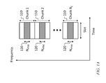
- FIG. 1A is a time-frequency diagram of a phase tracking reference signal structure, according to an embodiment of the present disclosure
- FIG. 1B is a time-frequency diagram of a phase tracking reference signal structure, according to an embodiment of the present disclosure
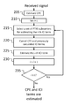
- FIG. 2 is a flowchart of a method for estimating common phase error and inter-carrier interference, according to an embodiment of the present disclosure
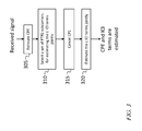
- FIG. 3 is a flowchart of a method for estimating common phase error and inter-carrier interference, according to an embodiment of the present disclosure
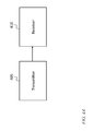
- FIG. 4A is a block diagram of a transmitter and a receiver, according to an embodiment of the present disclosure.
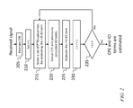
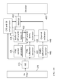
- FIG. 4B is a block diagram of a system for estimating, and compensating for, common phase error and inter-carrier interference, according to an embodiment of the present disclosure
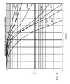
- FIG. 5 is a graph of simulated performance, according to an embodiment of the present disclosure.
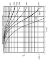
- FIG. 6 is a graph of simulated performance, according to an embodiment of the present disclosure.
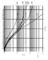
- FIG. 7 is a graph of simulated performance, according to an embodiment of the present disclosure.
- FIG. 8 is a graph of simulated performance, according to an embodiment of the present disclosure.
- An OFDM transmission structure may include a plurality of uniformly spaced subcarriers, e.g., 1024 subcarriers, separated by 15 kHz from each other. Of these subcarriers, a subset, e.g., 600 subcarriers, may be used to transmit data and PTRS subcarriers; this subset may be referred to as the resource block (RB) allocation. The remainder of the subcarriers may be reserved for other purposes such as guard bands. Each subcarrier may be numbered with an index. For example, the subcarriers may be given consecutive numbers beginning with 1 for the lowest-frequency subcarrier in the resource block allocation.
- the center of the frequency range spanned by the plurality of subcarriers may be at microwave or millimeter-wave frequencies, e.g., at 40 GHz or at 60 GHz.
- Each subcarrier may be independently modulated, e.g., using 8 ⁇ 8 quadrature amplitude modulation (64 QAM) for data subcarriers, and using quadrature phase shift keying (QPSK) modulation for the PTRS subcarriers.
- Each subcarrier may transmit a stream of symbols (each corresponding to an interval of time).
- the length of the symbol interval may be selected to be the reciprocal of the spacing between subcarriers (e.g., the symbol interval may be selected to be 1/15,000 seconds) so that each of the subcarriers is orthogonal to all of the other subcarriers during each symbol interval.
- the New Radio standard uses OFDM.
- Y[l] is the received signal at subcarrier l
- X[k] is the transmitted signal at subcarrier k
- H[k] is the channel at subcarrier k
- J[k] is the k-th term of inter-carrier interference
- N is the FFT size
- ⁇ n is the phase noise realization at time sample n.
- J[0] is the common phase error
- J[l ⁇ k] is inter-carrier interference
- the channel at subcarrier k (i.e., the transfer function of the channel, at the center frequency of subcarrier k) may be estimated using a demodulation reference signal (DMRS) that may be transmitted along with data and the PTRS subcarriers.
- DMRS demodulation reference signal
- the PTRS structure i.e., the set of subcarriers used to transmit the PTRS signals, may affect the ability of a receiver to perform interference cancellation, e.g., in particular, the ability of a receiver to compensate for inter-carrier interference. Accordingly, in some embodiments a group distributed structure is used. This structure is shown in FIGS. 1A and 1B , in one embodiment.
- the subcarriers within the resource block allocation are grouped into N c groups of adjacent subcarriers; these groups may be referred to as “chunks”. Each chunk includes N PTRS adjacent PTRS subcarriers.
- FIG. 1A is a time-frequency diagram of a phase tracking reference signal structure, according to an embodiment of the present disclosure.
- 1A shows the grouping of subcarriers into chunks 110 and the allocation, within each chunk, to PTRS signals, of a set 120 of N PTRS adjacent subcarriers.
- FIG. 1B is a time-frequency diagram of a phase tracking reference signal structure, according to an embodiment of the present disclosure.
- FIG. 1B shows this numbering convention for the set 120 of PTRS subcarriers in one of the chunks 110 , chunk 1 .
- inter-carrier interference estimation and common phase error estimation and compensation may be performed according to two alternate methods, one of which is referred to herein as successive interference cancellation (SIC) and the other of which is referred to as joint estimation of inter-carrier interference.
- SIC successive interference cancellation
- FIG. 2 is a flowchart of a method for estimating common phase error and inter-carrier interference, according to an embodiment of the present disclosure.
- ⁇ [0] (( ⁇ [ ]X[ ] ) H Y[ ])
- ⁇ [ ] is a diagonal matrix the p-th diagonal element of which is equal to the estimated channel response for the p-th subcarrier from among the set ,
- X[ ] is the transmitted signal in subcarriers from among the set ,
- Y[ ] is the received signal in subcarriers from among the set .
- H as a superscript denotes a conjugate transpose.
- a set of L inter-carrier interference terms may be iteratively estimated, in a loop including 210 through 235 .
- the value of L providing acceptable performance may depend on N PTRS , on N c , and on the phase noise characteristics. L may be selected offline (e.g., using simulations to identify a value that provides good performance that is relatively insensitive to the phase noise characteristics) and stored in a buffer.
- the loop index i is initialized to 1.
- the estimated common phase error, and the first through (i ⁇ 1)-th inter-carrier interference terms may be canceled from the received signal according to:
- ij ⁇ k 1(i+1) , . . . , k 1(N PTRS ⁇ j) , . . . , k N c (i+1) , . . . k N c (N PTRS ⁇ j) ⁇ (where k pq is the q-th subcarrier of the p-th group of subcarriers of the phase tracking reference signal subcarriers),
- ⁇ [ ij ] is a diagonal matrix the p-th diagonal element of which is equal to the estimated channel response for the p-th subcarrier from among the set ij ,
- X[ pq ] is the transmitted signal in subcarriers from among the set pq ,
- Y[ ii ] is the received signal in subcarriers from among the set ii ,
- ⁇ [0] is the estimated common phase error
- ⁇ [p] for p not equal to zero, is the estimated p-th inter-carrier interference term.
- Y SIC [ ii ] may be referred to as the i-th compensated received signal.
- the next (i-th) inter-carrier interference term may then be estimated, at 225 , based on the i-th compensated received signal, according to:
- the index i may then be incremented (at 230 ) and compared to the loop limit L (at 235 ), and the loop may repeat until i exceeds L.
- Y ICI comp [l] ⁇ *[0] Y[l]+ ⁇ *[1] Y[l+ 1]+ ⁇ *[ ⁇ 1] Y[l ⁇ 1]+ . . . + ⁇ *[L]Y[l+L]+ ⁇ *[ ⁇ L]Y[l ⁇ L].
- the above expression may be seen to be a finite impulse response (FIR) filter.
- FIG. 3 is a flowchart of a method for estimating common phase error and inter-carrier interference, according to an embodiment of the present disclosure.
- ⁇ [0] (( ⁇ [ ] X[ ] ) H Y[ ] ).
- a set of PTRS subcarriers suitable for jointly estimating the L inter-carrier interference terms is selected. This may be done by selecting the set LL as the set of PTRS subcarriers to be used for jointly estimating the L inter-carrier interference terms.
- k pq is the q-th subcarrier of the p th group of subcarriers of the phase tracking reference signal subcarriers
- ⁇ [ LL ] is a diagonal matrix the p th diagonal element of which is equal to the estimated channel response for the p th subcarrier from among the set LL ,
- X[ LL ] is the transmitted signal in subcarriers from among the set LL ,
- Y[ LL ] is the received signal in subcarriers from among the set LL .
- ⁇ [0] is the estimated common phase error.
- the L inter-carrier interference terms may then be estimated jointly according to
- a i Re ⁇ [ (L ⁇ i)(L+i) ]X[ (L ⁇ i)(L+i) ] ⁇ Re ⁇ [ (L+i)(L ⁇ i) ]X[ (L+i)(L ⁇ i) ] ⁇
- B i ⁇ m ⁇ [ (L ⁇ i)(L+i) ]X[ (L ⁇ i)(L+i) ] ⁇ Im ⁇ [ (L+i)(L ⁇ i) ]X[ (L+i)(L ⁇ i) ] ⁇
- C i Im ⁇ [ (L ⁇ i)(L+i) ]X[ (L ⁇ i)(L+i) ] ⁇ Im ⁇ [ (L+i)(L ⁇ i) ]X[ (L+i)(L ⁇ i) ] ⁇
- D i Re ⁇ [ (L ⁇ i)(L+i)
- FIG. 4A is a block diagram of a transmitter 405 and a receiver 410 , according to an embodiment of the present disclosure.
- FIG. 4A shows a block diagram of a transmitter (which may transmit a PTRS structure according to an embodiment of the present disclosure) and a receiver (which may employ a system and method, according to an embodiment of the present disclosure, for estimating, and compensating for, both common phase error, and inter-carrier interference).
- FIG. 4B is a block diagram of a system for estimating, and compensating for, common phase error and inter-carrier interference, according to an embodiment of the present disclosure.
- FIG. 4B shows a block diagram for two embodiments, one of which employs successive interference cancellation (SIC) and the other of which employs joint estimation of inter-carrier interference.
- SIC successive interference cancellation
- PTRS subcarriers are extracted from a frequency-domain signal (the output of the FFT 415 ) by a PTRS subcarrier extractor 420 , and the transmitted PTRS signal (X[ pq ]) is generated in the PTRS symbol generator 425 using the known PTRS pilots.
- Common phase error and inter-carrier interference terms are estimated by the CPE and ICI terms estimator 430 and buffered in the buffer 435 of CPE and ICI terms.
- the CPE and ICI terms estimator receives the estimated channel response ( ⁇ [k]) from the channel estimator 440 , l which estimates the response of each channel using demodulation reference signals (DMRSs) received from the DMRS subcarriers extractor 445 .
- DMRSs demodulation reference signals
- the dashed arrow 450 indicating a flow of information from the buffer of CPE and ICI terms back to the CPE and ICI terms estimator, is used (i.e., the information flow is present) in the embodiment employing successive interference cancellation and absent from the embodiment employing joint estimation of inter-carrier interference.
- the final compensated received signal Y ICI comp [l] is calculated by the CPE and ICI compensator 455 , the output of which is fed (along with the output of the channel estimator) to the detector 460 (the output of which is fed to the decoder 465 ).
- Rx (receive) filter 470 may be a separate processing circuit (discussed in further detail below), or each of these blocks may (equivalently) be implemented as a separate portion of a single processing circuit, or some or all of them may be implemented in hardware or firmware executed by a processing circuit that is configured to operate as a stored-program computer.
- processing circuit is used herein to mean any combination of hardware, firmware, and software, employed to process data or digital signals.
- Processing circuit hardware may include, for example, application specific integrated circuits (ASICs), general purpose or special purpose central processing units (CPUs), digital signal processors (DSPs), graphics processing units (GPUs), and programmable logic devices such as field programmable gate arrays (FPGAs).
- ASICs application specific integrated circuits
- CPUs general purpose or special purpose central processing units
- DSPs digital signal processors
- GPUs graphics processing units
- FPGAs programmable logic devices
- each function is performed either by hardware configured, i.e., hard-wired, to perform that function, or by more general purpose hardware, such as a CPU, configured to execute instructions stored in a non-transitory storage medium.
- a processing circuit may be fabricated on a single printed circuit board (PCB) or distributed over several interconnected PCBs.
- a processing circuit may contain other processing circuits; for example a processing circuit may include two processing circuits, an FPGA and a CPU, interconnected on a PCB.
- FIGS. 5-8 is a graph of simulated performance, according to an embodiment of the present disclosure.
- FIGS. 5-8 show simulated performance for various embodiments. The simulations illustrate that significant improvements in performance are possible, using common phase error and inter-carrier interference compensation according to embodiments of the present disclosure.
- FIGS. 5 and 6 use simulations in which the effective code rate is fixed, and FIGS. 7 and 8 use simulations in which the transmit block size is fixed.
- FIGS. 5 and 7 use simulations in which successive interference cancellation is employed, and
- FIGS. 6 and 8 use simulations in which joint estimation of inter-carrier interference is employed.
- Each of the graphs of FIGS. 5-8 shows a plurality of curves, numbered in order.
- the first curve in each of FIGS. 5 and 6 i.e., each of curves 501 and 601 ) shows the results for a simulation in which no compensation is performed.
- curves 508 and 608 show the results for a simulation in which “genie” compensation is performed, i.e., in which the true common phase error and inter-carrier interference (which are known within the simulation) are used in the compensation.
- the second through seventh curves in FIGS. 5 and 6 show the results for simulations in which N c is 50, 25, 10, 5, 2, and 1, respectively.
- the first seven curves of each of FIGS. 5 and 6 have 1 resource element (RE) per resource block (RB), 1 RE per 1 RB, 2 REs per 2 RBs, 5 REs per 5 RBs, 10 REs per 10 RBs, 25 REs per 25 RBs, and 50 REs per 50 RBs, respectively.
- RE resource element
- curves 701 - 707 the numbers of PTRS subcarriers are 0, 5, 10, 25, 25, 50, and 50, respectively, and the numbers of chunks are 0, 5, 10, 25, 1, 50, 2, respectively.
- Curves 701 , 702 , and 703 show the results for simulations in which no compensation is used. Compensation is used in the simulations for curves 704 - 707 , with curves 704 and 706 having common phase error compensation only, and curves 705 and 707 also having compensation for 3 and 6 inter-carrier interference terms, respectively.
- curves 801 - 805 in curves 801 - 805 , the numbers of PTRS subcarriers are 0, 5, 10, 25, and 25 , respectively, and the numbers of chunks are 0, 5, 10, 25, and 1, respectively.
- Curves 801 and 802 show the results for simulations in which no compensation is used. Compensation is used in the simulations for curves 803 - 805 , with curves 803 and 804 having common phase error compensation only, and curve 805 also having compensation for 4 inter-carrier interference terms.
- the group distributed PTRS structure may make it possible to handle those phase noise models with wide PSD relative to the subcarrier spacing.
- the group distributed PTRS structure may also have an advantage over a fully localized PTRS structure which may suffer from a deep fading problem if the allocated PTRS subcarriers are experiencing a poor quality channel condition.
- Some embodiments further provide a frequency domain successive interference cancellation method and joint method for inter-carrier interference estimation, and a frequency domain FIR filter for inter-carrier interference compensation that may improve the performance significantly compared to common phase error compensation only.
- calculating a first value “based on” a second value means calculating the first value as the output of a function the input to which includes the second value.
- “canceling” an estimated error from a signal, or “compensating” a signal for an error means making a correction to a signal based on the estimated error; this need not result in entirely eliminating, from the signal, the effect of the error.
- two subcarriers are “adjacent” if there are no other subcarriers between them in frequency.
- a group of carriers is referred to as a group of “adjacent subcarriers” if, for every two carriers in the group there are no subcarriers, not in the group, between the two carriers in frequency.
- first”, “second”, “third”, etc. may be used herein to describe various elements, components, regions, layers and/or sections, these elements, components, regions, layers and/or sections should not be limited by these terms. These terms are only used to distinguish one element, component, region, layer or section from another element, component, region, layer or section. Thus, a first element, component, region, layer or section discussed herein could be termed a second element, component, region, layer or section, without departing from the spirit and scope of the inventive concept.
- the terms “major component” refers to a component that is present in a composition, polymer, or product in an amount greater than an amount of any other single component in the composition or product.
- the term “primary component” refers to a component that makes up at least 50% by weight or more of the composition, polymer, or product.
- the term “major portion”, when applied to a plurality of items, means at least half of the items.
Landscapes
- Engineering & Computer Science (AREA)
- Signal Processing (AREA)
- Computer Networks & Wireless Communication (AREA)
- Power Engineering (AREA)
- Noise Elimination (AREA)
- Radio Transmission System (AREA)
Priority Applications (6)
| Application Number | Priority Date | Filing Date | Title |
|---|---|---|---|
| US15/880,419 US10341066B2 (en) | 2017-08-03 | 2018-01-25 | System and method for common phase error and inter-carrier interference estimation and compensation |
| KR1020180026241A KR102513092B1 (ko) | 2017-08-03 | 2018-03-06 | 공통 위상 오차 및 부반송파간 간섭 추정 및 보상 방법, 및 데이터 송신 방법 |
| TW107112342A TWI749210B (zh) | 2017-08-03 | 2018-04-11 | 共同相位誤差和載波間干擾估計與補償的方法、以及傳送及接收資料的方法 |
| CN201810621014.3A CN109391579B (zh) | 2017-08-03 | 2018-06-15 | 用于共同相位误差及载波间干扰估测及补偿的方法 |
| US16/403,926 US10868644B2 (en) | 2017-08-03 | 2019-05-06 | System and method for common phase error and inter-carrier interference estimation and compensation |
| US16/403,889 US10944520B2 (en) | 2017-08-03 | 2019-05-06 | System and method for common phase error and inter-carrier interference estimation and compensation |
Applications Claiming Priority (2)
| Application Number | Priority Date | Filing Date | Title |
|---|---|---|---|
| US201762541035P | 2017-08-03 | 2017-08-03 | |
| US15/880,419 US10341066B2 (en) | 2017-08-03 | 2018-01-25 | System and method for common phase error and inter-carrier interference estimation and compensation |
Related Child Applications (2)
| Application Number | Title | Priority Date | Filing Date |
|---|---|---|---|
| US16/403,889 Division US10944520B2 (en) | 2017-08-03 | 2019-05-06 | System and method for common phase error and inter-carrier interference estimation and compensation |
| US16/403,926 Continuation US10868644B2 (en) | 2017-08-03 | 2019-05-06 | System and method for common phase error and inter-carrier interference estimation and compensation |
Publications (2)
| Publication Number | Publication Date |
|---|---|
| US20190044673A1 US20190044673A1 (en) | 2019-02-07 |
| US10341066B2 true US10341066B2 (en) | 2019-07-02 |
Family
ID=65230100
Family Applications (3)
| Application Number | Title | Priority Date | Filing Date |
|---|---|---|---|
| US15/880,419 Active US10341066B2 (en) | 2017-08-03 | 2018-01-25 | System and method for common phase error and inter-carrier interference estimation and compensation |
| US16/403,889 Active 2038-03-10 US10944520B2 (en) | 2017-08-03 | 2019-05-06 | System and method for common phase error and inter-carrier interference estimation and compensation |
| US16/403,926 Active US10868644B2 (en) | 2017-08-03 | 2019-05-06 | System and method for common phase error and inter-carrier interference estimation and compensation |
Family Applications After (2)
| Application Number | Title | Priority Date | Filing Date |
|---|---|---|---|
| US16/403,889 Active 2038-03-10 US10944520B2 (en) | 2017-08-03 | 2019-05-06 | System and method for common phase error and inter-carrier interference estimation and compensation |
| US16/403,926 Active US10868644B2 (en) | 2017-08-03 | 2019-05-06 | System and method for common phase error and inter-carrier interference estimation and compensation |
Country Status (4)
| Country | Link |
|---|---|
| US (3) | US10341066B2 (zh) |
| KR (1) | KR102513092B1 (zh) |
| CN (1) | CN109391579B (zh) |
| TW (1) | TWI749210B (zh) |
Cited By (1)
| Publication number | Priority date | Publication date | Assignee | Title |
|---|---|---|---|---|
| US20190327043A1 (en) * | 2017-08-03 | 2019-10-24 | Samsung Electronics Co., Ltd. | System and method for common phase error and inter-carrier interference estimation and compensation |
Families Citing this family (16)
| Publication number | Priority date | Publication date | Assignee | Title |
|---|---|---|---|---|
| EP3665878B1 (en) * | 2017-08-11 | 2022-06-22 | Nokia Technologies Oy | Inter-carrier interference compensation |
| US10952187B2 (en) * | 2018-05-04 | 2021-03-16 | Cavium, Llc | Methods and apparatus for providing a demapping system to demap uplink transmissions |
| US11683203B2 (en) | 2018-05-04 | 2023-06-20 | Marvell Asia Pte, Ltd. | Methods and apparatus for providing a demapping system with phase compensation to demap uplink transmissions |
| US20220060361A1 (en) * | 2019-03-14 | 2022-02-24 | Apple Inc. | Systems and methods of phase-tracking reference signal transmission for ofdm |
| US20230006783A1 (en) * | 2019-09-30 | 2023-01-05 | Nec Corporation | Methods for communication, terminal device, network device, and computer readable medium |
| CN114070682B (zh) * | 2020-07-31 | 2022-10-04 | 华为技术有限公司 | 相位噪声估计方法和装置 |
| CN116938651A (zh) * | 2020-08-07 | 2023-10-24 | 瑞典爱立信有限公司 | Ptrs与nr参考信号的共存 |
| US11855814B2 (en) | 2020-08-07 | 2023-12-26 | Telefonaktiebolaget Lm Ericsson (Publ) | De-ICI filter estimation for phase noise mitigation |
| CN114338306B (zh) * | 2020-09-29 | 2024-05-03 | 大唐移动通信设备有限公司 | 相位噪声补偿方法及装置 |
| CN114337951B (zh) * | 2020-09-29 | 2024-01-16 | 大唐移动通信设备有限公司 | 信号传输方法及装置、终端、网络侧设备 |
| WO2022081078A1 (en) * | 2020-10-16 | 2022-04-21 | Telefonaktiebolaget Lm Ericsson (Publ) | Enabling inter carrier interface compensation for interleaved mapping from virtual to physical resource blocks |
| CN112688891B (zh) * | 2020-12-30 | 2023-09-01 | 中电科思仪科技(安徽)有限公司 | 一种5g毫米波上行信号相位噪声估计与补偿装置及方法 |
| US11824691B2 (en) * | 2021-03-25 | 2023-11-21 | Telefonaktiebolaget Lm Ericsson (Publ) | Receiver for a wireless communication network |
| US11637726B2 (en) * | 2021-03-25 | 2023-04-25 | Telefonaktiebolaget Lm Ericsson (Publ) | Receiver for a wireless communication network |
| CN115499112A (zh) * | 2021-06-19 | 2022-12-20 | 华为技术有限公司 | 符号传输的方法和通信装置 |
| CN114726689B (zh) * | 2022-06-06 | 2022-09-30 | 新华三技术有限公司 | 一种信号估计的方法及装置 |
Citations (7)
| Publication number | Priority date | Publication date | Assignee | Title |
|---|---|---|---|---|
| US20050078599A1 (en) * | 2003-10-10 | 2005-04-14 | Sergei Zhidkov | Apparatus, method and computer program for correcting common phase error of OFDM signal symbols |
| US20070025461A1 (en) * | 2005-07-29 | 2007-02-01 | Samsung Electronics Co., Ltd. | Phase noise compensation apparatus and an OFDM system having the apparatus and method thereof |
| US20070223359A1 (en) | 2006-03-24 | 2007-09-27 | Shupeng Li | Method of OFDMA tone interference cancellation |
| KR101089502B1 (ko) | 2009-12-30 | 2011-12-05 | 전자부품연구원 | Ofdm시스템에서 시변채널 정보를 이용한 ici 제거 방법 |
| US8261169B2 (en) | 2006-05-19 | 2012-09-04 | Panasonic Corporation | Wireless communication apparatus and wireless communication method |
| US8311550B2 (en) | 2007-06-19 | 2012-11-13 | Ntt Docomo, Inc. | Radio communication control method, base station apparatus and user apparatus |
| US9722768B2 (en) | 2013-11-15 | 2017-08-01 | National Institute Of Advanced Industrial Science And Technology | Received signal processing device, communication system, and received signal processing method |
Family Cites Families (18)
| Publication number | Priority date | Publication date | Assignee | Title |
|---|---|---|---|---|
| WO2001020818A1 (en) * | 1999-09-17 | 2001-03-22 | Qualcomm Incorporated | System and method for synchronizing base stations in cellular and pcs networks |
| CN101771656B (zh) * | 2001-06-22 | 2014-07-23 | 汤姆森许可公司 | 在ofdm接收机中补偿载波频率偏移的方法和系统 |
| KR100530262B1 (ko) * | 2003-12-27 | 2005-11-22 | 한국전자통신연구원 | 무선 랜 시스템의 위상잡음 제거 장치 및 그 방법 |
| KR100752641B1 (ko) * | 2005-01-25 | 2007-08-29 | 삼성전자주식회사 | 데이터 서브캐리어를 이용하여 공통 위상을 추정하는ofdm 신호 수신기 및 방법 |
| JP2006352746A (ja) * | 2005-06-20 | 2006-12-28 | Fujitsu Ltd | 直交周波数分割多重伝送用受信機 |
| CN101594338A (zh) * | 2008-05-30 | 2009-12-02 | 泰鼎多媒体技术(上海)有限公司 | 用于减小公共相位误差的方法及装置 |
| WO2014124097A2 (en) | 2013-02-06 | 2014-08-14 | Content Delivery Ads, Inc. | Internet vending machine/mobile vending machine system and method |
| US9154338B1 (en) * | 2014-04-18 | 2015-10-06 | Entropic Communications, Llc | System and method for IQ imbalance estimation |
| US9106472B1 (en) * | 2014-06-27 | 2015-08-11 | Ibiquity Digital Corporation | Channel state information (CSI) estimation and applications for in-band on-channel radio receivers |
| CN104683280B (zh) * | 2014-12-02 | 2018-04-24 | 北京星河亮点技术股份有限公司 | DFT-s-OFDM系统大频偏的精确估计方法 |
| KR101674832B1 (ko) * | 2015-11-13 | 2016-11-09 | 고려대학교 산학협력단 | 각 안테나 단마다 독립적인 발진기를 가지는 2×2 다중 입출력 시스템에서 위상잡음제거 방법 및 장치 |
| WO2017188591A1 (ko) * | 2016-04-25 | 2017-11-02 | 엘지전자 주식회사 | 무선 통신 시스템에서 위상 잡음 추정을 위한 신호 전송 방법 |
| CN110024315B (zh) | 2016-11-04 | 2022-05-03 | 瑞典爱立信有限公司 | 取决于调度参数的pt-rs配置 |
| JP7091329B2 (ja) * | 2016-11-18 | 2022-06-27 | オッポ広東移動通信有限公司 | 基準信号の伝送方法及び通信装置 |
| CN108259401B (zh) * | 2016-12-28 | 2020-09-15 | 电信科学技术研究院 | 参考信号发送方法和相位噪声确定方法及相关装置 |
| WO2018126633A1 (en) * | 2017-01-05 | 2018-07-12 | Telefonaktiebolaget Lm Ericsson (Publ) | Methods and devices for facilitating discontinuous reception |
| CN108632189B (zh) * | 2017-03-22 | 2021-01-08 | 展讯通信(上海)有限公司 | 上行数据的发送方法、装置及用户设备 |
| US10341066B2 (en) * | 2017-08-03 | 2019-07-02 | Samsung Electronics Co., Ltd. | System and method for common phase error and inter-carrier interference estimation and compensation |
-
2018
- 2018-01-25 US US15/880,419 patent/US10341066B2/en active Active
- 2018-03-06 KR KR1020180026241A patent/KR102513092B1/ko active IP Right Grant
- 2018-04-11 TW TW107112342A patent/TWI749210B/zh active
- 2018-06-15 CN CN201810621014.3A patent/CN109391579B/zh active Active
-
2019
- 2019-05-06 US US16/403,889 patent/US10944520B2/en active Active
- 2019-05-06 US US16/403,926 patent/US10868644B2/en active Active
Patent Citations (7)
| Publication number | Priority date | Publication date | Assignee | Title |
|---|---|---|---|---|
| US20050078599A1 (en) * | 2003-10-10 | 2005-04-14 | Sergei Zhidkov | Apparatus, method and computer program for correcting common phase error of OFDM signal symbols |
| US20070025461A1 (en) * | 2005-07-29 | 2007-02-01 | Samsung Electronics Co., Ltd. | Phase noise compensation apparatus and an OFDM system having the apparatus and method thereof |
| US20070223359A1 (en) | 2006-03-24 | 2007-09-27 | Shupeng Li | Method of OFDMA tone interference cancellation |
| US8261169B2 (en) | 2006-05-19 | 2012-09-04 | Panasonic Corporation | Wireless communication apparatus and wireless communication method |
| US8311550B2 (en) | 2007-06-19 | 2012-11-13 | Ntt Docomo, Inc. | Radio communication control method, base station apparatus and user apparatus |
| KR101089502B1 (ko) | 2009-12-30 | 2011-12-05 | 전자부품연구원 | Ofdm시스템에서 시변채널 정보를 이용한 ici 제거 방법 |
| US9722768B2 (en) | 2013-11-15 | 2017-08-01 | National Institute Of Advanced Industrial Science And Technology | Received signal processing device, communication system, and received signal processing method |
Cited By (2)
| Publication number | Priority date | Publication date | Assignee | Title |
|---|---|---|---|---|
| US20190327043A1 (en) * | 2017-08-03 | 2019-10-24 | Samsung Electronics Co., Ltd. | System and method for common phase error and inter-carrier interference estimation and compensation |
| US10868644B2 (en) * | 2017-08-03 | 2020-12-15 | Samsung Electronics Co., Ltd. | System and method for common phase error and inter-carrier interference estimation and compensation |
Also Published As
| Publication number | Publication date |
|---|---|
| CN109391579B (zh) | 2023-04-14 |
| TWI749210B (zh) | 2021-12-11 |
| US10868644B2 (en) | 2020-12-15 |
| TW201921849A (zh) | 2019-06-01 |
| US10944520B2 (en) | 2021-03-09 |
| US20190044673A1 (en) | 2019-02-07 |
| KR20190015072A (ko) | 2019-02-13 |
| KR102513092B1 (ko) | 2023-03-22 |
| US20190327043A1 (en) | 2019-10-24 |
| US20190327042A1 (en) | 2019-10-24 |
| CN109391579A (zh) | 2019-02-26 |
Similar Documents
| Publication | Publication Date | Title |
|---|---|---|
| US10868644B2 (en) | System and method for common phase error and inter-carrier interference estimation and compensation | |
| CN100596131C (zh) | 多载波信号发射方法和设备及多载波信号接收方法和设备 | |
| US20120014465A1 (en) | Iterative channel estimation method and apparatus for ici cancellation in multi-carrier | |
| US8718208B2 (en) | Recovery of data from a multi carrier signal | |
| US8811505B2 (en) | Radio channel model for ICI cancellation in multi-carrier systems | |
| CN101257470A (zh) | 正交频分复用系统中利用插入导频抑制相位噪声的方法 | |
| US20170265202A1 (en) | Time domain pilot of single-carrier mimo system and synchronization method thereof | |
| US8411773B2 (en) | Simplified equalization scheme for distributed resource allocation in multi-carrier systems | |
| JP6743327B2 (ja) | 無線通信システム、無線送信装置および無線受信装置 | |
| Kumar et al. | Evaluation of conventional and wavelet based OFDM system for ICI cancellation | |
| CN105119857B (zh) | 一种雷达站间低抖动、抗干扰信号通信链路技术 | |
| KR20100054987A (ko) | Ofdm 시스템에서의 주파수 추정을 위한 장치 및 방법 | |
| Khare et al. | Effect of Doppler frequency and ber in FFT based OFDM system with Rayleigh fading channel | |
| Jhingan et al. | Performance Analysis of FFT-OFDM and DWT-OFDM over AWGN Channel under the Effect of CFO | |
| Chen et al. | Partial fractional Fourier transform (PFRFT)-OFDM for underwater acoustic communication | |
| Munshi et al. | Design Simulation and Evaluation of SISO/MISO/MIMO OFDM Systems | |
| JP5645613B2 (ja) | 無線通信システム、送信機および受信機 | |
| US8737544B2 (en) | Method and apparatus of estimating frequency offset based on partial periodogram in wireless communication system | |
| Jhingan et al. | Performance assessment of OFDM utilizing FFT/DWT over rician channel effected by CFO | |
| Thabet et al. | Synchronization error reduction using guard-band allocation for wireless communication systems | |
| US8917585B2 (en) | Method for estimating a received signal and corresponding device | |
| Azmy et al. | Performance improvement of the OFDM system based on fractional Fourier transform over doubly dispersive channels | |
| Haripriya et al. | Analysis of carrier frequency offset in WFRFT-OFDM systems using MLE | |
| Nigam et al. | Performance evaluation of CFO in single carrier-FDMA | |
| Kalra et al. | Inter carrier interference analysis of scfdma system using frequency domain equalization |
Legal Events
| Date | Code | Title | Description |
|---|---|---|---|
| FEPP | Fee payment procedure |
Free format text: ENTITY STATUS SET TO UNDISCOUNTED (ORIGINAL EVENT CODE: BIG.); ENTITY STATUS OF PATENT OWNER: LARGE ENTITY |
|
| AS | Assignment |
Owner name: SAMSUNG ELECTRONICS CO., LTD., KOREA, REPUBLIC OF Free format text: ASSIGNMENT OF ASSIGNORS INTEREST;ASSIGNORS:MALEKI, HAMED;DAYAL, PRANAV;SONG, KEE-BONG;REEL/FRAME:047764/0227 Effective date: 20180125 |
|
| STPP | Information on status: patent application and granting procedure in general |
Free format text: NOTICE OF ALLOWANCE MAILED -- APPLICATION RECEIVED IN OFFICE OF PUBLICATIONS |
|
| STPP | Information on status: patent application and granting procedure in general |
Free format text: PUBLICATIONS -- ISSUE FEE PAYMENT VERIFIED |
|
| STCF | Information on status: patent grant |
Free format text: PATENTED CASE |
|
| MAFP | Maintenance fee payment |
Free format text: PAYMENT OF MAINTENANCE FEE, 4TH YEAR, LARGE ENTITY (ORIGINAL EVENT CODE: M1551); ENTITY STATUS OF PATENT OWNER: LARGE ENTITY Year of fee payment: 4 |