US1028362A - Shingle-bracket. - Google Patents
Shingle-bracket. Download PDFInfo
- Publication number
- US1028362A US1028362A US60095511A US1911600955A US1028362A US 1028362 A US1028362 A US 1028362A US 60095511 A US60095511 A US 60095511A US 1911600955 A US1911600955 A US 1911600955A US 1028362 A US1028362 A US 1028362A
- Authority
- US
- United States
- Prior art keywords
- platform
- housings
- shingle
- secured
- teeth
- Prior art date
- Legal status (The legal status is an assumption and is not a legal conclusion. Google has not performed a legal analysis and makes no representation as to the accuracy of the status listed.)
- Expired - Lifetime
Links
- 210000000078 claw Anatomy 0.000 description 3
- JCCNYMKQOSZNPW-UHFFFAOYSA-N loratadine Chemical compound C1CN(C(=O)OCC)CCC1=C1C2=NC=CC=C2CCC2=CC(Cl)=CC=C21 JCCNYMKQOSZNPW-UHFFFAOYSA-N 0.000 description 1
- 239000002184 metal Substances 0.000 description 1
- 239000002023 wood Substances 0.000 description 1
Images

Classifications
-
- E—FIXED CONSTRUCTIONS
- E06—DOORS, WINDOWS, SHUTTERS, OR ROLLER BLINDS IN GENERAL; LADDERS
- E06C—LADDERS
- E06C7/00—Component parts, supporting parts, or accessories
- E06C7/42—Ladder feet; Supports therefor
- E06C7/426—Height adjustable supports for receiving both ladder feet
-
- E—FIXED CONSTRUCTIONS
- E04—BUILDING
- E04G—SCAFFOLDING; FORMS; SHUTTERING; BUILDING IMPLEMENTS OR AIDS, OR THEIR USE; HANDLING BUILDING MATERIALS ON THE SITE; REPAIRING, BREAKING-UP OR OTHER WORK ON EXISTING BUILDINGS
- E04G3/00—Scaffolds essentially supported by building constructions, e.g. adjustable in height
- E04G3/24—Scaffolds essentially supported by building constructions, e.g. adjustable in height specially adapted for particular parts of buildings or for buildings of particular shape, e.g. chimney stacks or pylons
- E04G3/26—Scaffolds essentially supported by building constructions, e.g. adjustable in height specially adapted for particular parts of buildings or for buildings of particular shape, e.g. chimney stacks or pylons specially adapted for working on roofs
Definitions
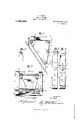
- This invention relates to scaffolds of the type which are principally used in shingling a roof and the principal object of the same is to provide a means whereby the scaffold nay be adjusted so that the scaffold may be used on roofs slanting to different degrees and yet have the platform of the scaffold horizontal.
- Figure 1 is a perspective view of the improved scaffold and shows the same positioned upon a roof.
- Fig. 2 is a side view of the scaffold.
- Fig. 3 is a bottom plan view of the scaffold.
- Fig. l is an enlarged view of one of the struts.
- Fig. 5 is a view of one of the struts looking from the opposite side from that shown in Fig. 4;.
- Fig. 6 is an enlarged sectional view of a portion of one of the struts and shows the manner of connecting the two sections.
- Fig. 7 is an enlarged fragmentary view of the end of one of the struts.
- the improved scafiold comprises a platform 1, which is preferably made from wood.
- a pair of supporting bars 2 and 3 are secured to the under surfaces of the platform 1 by means of the bolts A which pass through the platform and bars.
- the supporting bars are secured at one end near the center of the platform and are outwardly curved and have their ends positioned near the sides of the platform.
- the ends of the braces are rolled to provide housings 5 and 6, the housings at each end of the braces being in alinement.
- the rods 6 and 7 are passed through the alined housings, and have their outer ends extending beyond the outer ends of the housings.
- a strut is positioned upon each outer end portion of the rod 7 and holds the platform in a horizontal position.
- the strut comprises an upper section 8 and a lower section 9.
- the section 8 has its upper portion rolled to form a housing 8 which surrounds the outer end Specification of Letters Patent.
- the lower section 9 is provided with a pair of arms 10 which surround the section 8 and form a means for slidably connecting the sections together.
- the section 8 is provided with an opening near its lower end and the section 9 is provided with a longitudinal series of openings 11.
- a bolt 12 passes through one of the openings 11 and through the opening formed in the end of the section 8 to hold the strut in an adjusted position, the bolt being held in place by a wing nut 13.
- the lower ends of the section 9 are rolled to form housings I L through which there is passed the rod 15, which extends to either side of the housings.
- a pair of ties 16 each has its ends filed to provide a pair of upper claw teeth 17 and lower claw teeth 18.
- the upper teeth are bent back upon the body of the tie at approximately an angle of 45 degrees and the lower teeth are curved downwardly and approximately at an angle parallel with the angle of the upper teeth.
- a strip of metal 19 is secured to the upper portion of each of the ties and has its free end curved to form a housing 20, which surrounds the outer ends of the rod 6 and which is held in place by means of nuts, or other desired securing means.
- a similar strip 21 is secured near the lower end of each of the ties and has its free end rolled to provide housings 21 which are mounted upon the outer ends of the rods 15 where they are held by means of nuts or other desired securing means.
- the angle of the roof is ascertained and the struts are moved to bring the ties at approximately the same angle to the platform.
- the platform is then placed upon the roof and the claw teeth 17 and 18 sink into the roof as clearly shown in Fig. 2.
- the upper teeth and the lower teeth positioned at an angle shown there is no danger of the platform slipping as the greater strain there is placed upon the platform, the deeper the teeth will sink into the roof, and the tighter the platform will hold. It should be noted however, that the teeth do not sink deep enough into the roof to cause the same to leak.
- a device of the character described comprising an adjustable platform, curved supporting bars secured to the under side of said platform, the inner Widely spaced ends of said supporting bars being secured upon a transverse rod at the inner side of said platform and the other more narrowly spaced ends being secured upon a transverse rod which is carried by the upper sections of adjustable struts which support the outer portion of the platform, and means to connect the lower ends of said adjustable struts with an inner transverse rod secured upon toothed ties which are also secured upon the first mentioned transverse rod.
Landscapes
- Engineering & Computer Science (AREA)
- Architecture (AREA)
- Mechanical Engineering (AREA)
- Civil Engineering (AREA)
- Structural Engineering (AREA)
- Joining Of Building Structures In Genera (AREA)
Description
V. D. KING.
SHINGLE BRACKET.
APPLICATION FILED JAN. 6, 1911.
Patented June 4, 1912.
2 SHEETS-SHEET l.
Hi M lk INVENTOR \f. D. m
Altornzy WITNESSES COLUMBIA PMNOGRAPH C0-.WASHXNGTON. D. C.
V. D. KING.
SHINGLE BRACKET.
APPLICATION FILED JAN. 6, 1911.
Patented June 4, 1912.
2 SHEETS-SHEETZ.
TAT PATENT SHINGLE-BRACKET.
To all whom it may concern:
Be it known that I, VERSAL D. Kine, a citizen of the United States, residing at Greensboro, in the county of Orleans and State of Vermont, have invented certain new and useful Improvements in Shingle- Brackets, of which the following is a specification, reference being had therein to the accompanying drawing.
This invention relates to scaffolds of the type which are principally used in shingling a roof and the principal object of the same is to provide a means whereby the scaffold nay be adjusted so that the scaffold may be used on roofs slanting to different degrees and yet have the platform of the scaffold horizontal.
This invention is illustrated in the accompanying drawings, wherein Figure 1 is a perspective view of the improved scaffold and shows the same positioned upon a roof. Fig. 2 is a side view of the scaffold. Fig. 3 is a bottom plan view of the scaffold. Fig. l is an enlarged view of one of the struts. Fig. 5 is a view of one of the struts looking from the opposite side from that shown in Fig. 4;. Fig. 6 is an enlarged sectional view of a portion of one of the struts and shows the manner of connecting the two sections. Fig. 7 is an enlarged fragmentary view of the end of one of the struts.
Referring to the accompanying drawings by numerals it will be seen that the improved scafiold comprises a platform 1, which is preferably made from wood. A pair of supporting bars 2 and 3 are secured to the under surfaces of the platform 1 by means of the bolts A which pass through the platform and bars. The supporting bars are secured at one end near the center of the platform and are outwardly curved and have their ends positioned near the sides of the platform. The ends of the braces are rolled to provide housings 5 and 6, the housings at each end of the braces being in alinement. The rods 6 and 7 are passed through the alined housings, and have their outer ends extending beyond the outer ends of the housings.
A strut is positioned upon each outer end portion of the rod 7 and holds the platform in a horizontal position. The strut comprises an upper section 8 and a lower section 9. The section 8 has its upper portion rolled to form a housing 8 which surrounds the outer end Specification of Letters Patent.
Application filed January 5, 1911.
Patented June a, 1912. Serial No. 600,955.
portion of the rod 7, and by means of which the strut is pivotally connected with the rod. The struts are held upon the rods by means of nuts, or any other desired means. The lower section 9 is provided with a pair of arms 10 which surround the section 8 and form a means for slidably connecting the sections together. The section 8 is provided with an opening near its lower end and the section 9 is provided with a longitudinal series of openings 11. A bolt 12 passes through one of the openings 11 and through the opening formed in the end of the section 8 to hold the strut in an adjusted position, the bolt being held in place by a wing nut 13. The lower ends of the section 9 are rolled to form housings I L through which there is passed the rod 15, which extends to either side of the housings. The fact that the ends of the braces having the housings 5 curve toward the sides of the platform brings the housings 5 and 14: in alinement and, as the rods 6 and 15 are of approximately the same length, there is an equal amount of rod extending to the sides of the two sets of housings.
A pair of ties 16, each has its ends filed to provide a pair of upper claw teeth 17 and lower claw teeth 18. The upper teeth are bent back upon the body of the tie at approximately an angle of 45 degrees and the lower teeth are curved downwardly and approximately at an angle parallel with the angle of the upper teeth. A strip of metal 19 is secured to the upper portion of each of the ties and has its free end curved to form a housing 20, which surrounds the outer ends of the rod 6 and which is held in place by means of nuts, or other desired securing means. A similar strip 21 is secured near the lower end of each of the ties and has its free end rolled to provide housings 21 which are mounted upon the outer ends of the rods 15 where they are held by means of nuts or other desired securing means.
In the operation the angle of the roof is ascertained and the struts are moved to bring the ties at approximately the same angle to the platform. The platform is then placed upon the roof and the claw teeth 17 and 18 sink into the roof as clearly shown in Fig. 2. By means of having the upper teeth and the lower teeth positioned at an angle shown there is no danger of the platform slipping as the greater strain there is placed upon the platform, the deeper the teeth will sink into the roof, and the tighter the platform will hold. It should be noted however, that the teeth do not sink deep enough into the roof to cause the same to leak.
lVhat I claim is A device of the character described, comprising an adjustable platform, curved supporting bars secured to the under side of said platform, the inner Widely spaced ends of said supporting bars being secured upon a transverse rod at the inner side of said platform and the other more narrowly spaced ends being secured upon a transverse rod which is carried by the upper sections of adjustable struts which support the outer portion of the platform, and means to connect the lower ends of said adjustable struts with an inner transverse rod secured upon toothed ties which are also secured upon the first mentioned transverse rod.
In testimony whereof I hereunto affix my signature in presence of two witnesses.
VERSAL D. KING. Witnesses WV. W. REIRDEN, P. L. W'EBsTnR.
Copies of this patent may be obtained for five cents each, by addressing the Commissioner of Patents, Washington, I). C.
Priority Applications (1)
| Application Number | Priority Date | Filing Date | Title |
|---|---|---|---|
| US60095511A US1028362A (en) | 1911-01-05 | 1911-01-05 | Shingle-bracket. |
Applications Claiming Priority (1)
| Application Number | Priority Date | Filing Date | Title |
|---|---|---|---|
| US60095511A US1028362A (en) | 1911-01-05 | 1911-01-05 | Shingle-bracket. |
Publications (1)
| Publication Number | Publication Date |
|---|---|
| US1028362A true US1028362A (en) | 1912-06-04 |
Family
ID=3096655
Family Applications (1)
| Application Number | Title | Priority Date | Filing Date |
|---|---|---|---|
| US60095511A Expired - Lifetime US1028362A (en) | 1911-01-05 | 1911-01-05 | Shingle-bracket. |
Country Status (1)
| Country | Link |
|---|---|
| US (1) | US1028362A (en) |
Cited By (17)
| Publication number | Priority date | Publication date | Assignee | Title |
|---|---|---|---|---|
| US2549638A (en) * | 1946-09-12 | 1951-04-17 | John C Rogghe | Scaffold |
| US2729517A (en) * | 1951-11-16 | 1956-01-03 | Sr Liday Elury Hamilton | Safety roof bracket |
| US2848282A (en) * | 1955-11-30 | 1958-08-19 | William M Weber | Ladder platform |
| US4632219A (en) * | 1985-08-12 | 1986-12-30 | Rayer Paul H | Roof ladder |
| US5050705A (en) * | 1990-08-08 | 1991-09-24 | Natwick Peter J | Roof creeper kit apparatus |
| US5211411A (en) * | 1991-03-13 | 1993-05-18 | Peter Oleksiuk | Roofing material carrier |
| US5249397A (en) * | 1992-01-16 | 1993-10-05 | Monaco Gary J | Knockdown roof platform for use on an inclined roof |
| US5570864A (en) * | 1994-05-13 | 1996-11-05 | Flores; Juan R. | Adjustable roofing stool |
| US5771992A (en) * | 1996-09-20 | 1998-06-30 | Snyder; Harry A. | Safety support structure for leveling a ladder |
| US6732480B1 (en) | 2003-06-18 | 2004-05-11 | Derek J. Smith | Adjustable roof platform |
| US20060226310A1 (en) * | 2004-03-29 | 2006-10-12 | Hall Peter V | Method of supporting tools and supplies upon a sloped surface |
| US20080142302A1 (en) * | 2006-12-14 | 2008-06-19 | World Way Safety S.R.O. | Step for temporary installation |
| US20110012002A1 (en) * | 2006-08-29 | 2011-01-20 | Steven Le Masurier | Safety device |
| US9016433B1 (en) | 2012-01-19 | 2015-04-28 | Robert S. Duffy | Firefighter safety device |
| US9404305B1 (en) | 2014-03-26 | 2016-08-02 | Mark S. Messick | Portable and adaptable platform |
| US9587408B1 (en) * | 2013-03-13 | 2017-03-07 | Troy Ray Brannon | Roof workman's utility box |
| US20220381034A1 (en) * | 2021-05-25 | 2022-12-01 | Dwight Smith | Roofing shingle delivery system |
-
1911
- 1911-01-05 US US60095511A patent/US1028362A/en not_active Expired - Lifetime
Cited By (19)
| Publication number | Priority date | Publication date | Assignee | Title |
|---|---|---|---|---|
| US2549638A (en) * | 1946-09-12 | 1951-04-17 | John C Rogghe | Scaffold |
| US2729517A (en) * | 1951-11-16 | 1956-01-03 | Sr Liday Elury Hamilton | Safety roof bracket |
| US2848282A (en) * | 1955-11-30 | 1958-08-19 | William M Weber | Ladder platform |
| US4632219A (en) * | 1985-08-12 | 1986-12-30 | Rayer Paul H | Roof ladder |
| US5050705A (en) * | 1990-08-08 | 1991-09-24 | Natwick Peter J | Roof creeper kit apparatus |
| US5211411A (en) * | 1991-03-13 | 1993-05-18 | Peter Oleksiuk | Roofing material carrier |
| US5249397A (en) * | 1992-01-16 | 1993-10-05 | Monaco Gary J | Knockdown roof platform for use on an inclined roof |
| US5570864A (en) * | 1994-05-13 | 1996-11-05 | Flores; Juan R. | Adjustable roofing stool |
| US5771992A (en) * | 1996-09-20 | 1998-06-30 | Snyder; Harry A. | Safety support structure for leveling a ladder |
| US6732480B1 (en) | 2003-06-18 | 2004-05-11 | Derek J. Smith | Adjustable roof platform |
| US20060226310A1 (en) * | 2004-03-29 | 2006-10-12 | Hall Peter V | Method of supporting tools and supplies upon a sloped surface |
| US20110012002A1 (en) * | 2006-08-29 | 2011-01-20 | Steven Le Masurier | Safety device |
| US8382056B2 (en) * | 2006-08-29 | 2013-02-26 | Steven Le Masurier | Safety device |
| US20080142302A1 (en) * | 2006-12-14 | 2008-06-19 | World Way Safety S.R.O. | Step for temporary installation |
| US9016433B1 (en) | 2012-01-19 | 2015-04-28 | Robert S. Duffy | Firefighter safety device |
| US9587408B1 (en) * | 2013-03-13 | 2017-03-07 | Troy Ray Brannon | Roof workman's utility box |
| US9404305B1 (en) | 2014-03-26 | 2016-08-02 | Mark S. Messick | Portable and adaptable platform |
| US20220381034A1 (en) * | 2021-05-25 | 2022-12-01 | Dwight Smith | Roofing shingle delivery system |
| US12371909B2 (en) * | 2021-05-25 | 2025-07-29 | Dwight Smith | Roofing shingle delivery system |
Similar Documents
| Publication | Publication Date | Title |
|---|---|---|
| US1028362A (en) | Shingle-bracket. | |
| US960565A (en) | Adjustable and reversible roof and ladder scaffolding-bracket. | |
| US1189514A (en) | Ladder structure. | |
| US826582A (en) | Scaffold. | |
| US505343A (en) | Edgar a | |
| US598100A (en) | Folding horse | |
| US988593A (en) | Folding fire-escape ladder. | |
| US590949A (en) | Adjustable roof-jack | |
| US667992A (en) | Scaffold-bracket. | |
| US781898A (en) | Ladder. | |
| US1662667A (en) | Bracket | |
| US657648A (en) | Knockdown trestle. | |
| US991182A (en) | Portable extension-scaffold. | |
| US680402A (en) | Combined ladder and truck. | |
| US1330162A (en) | Scaffold | |
| US1167988A (en) | Scaffold. | |
| US353768A (en) | Scaffold-bracket | |
| US1036945A (en) | Scaffold-bracket. | |
| US585506A (en) | Trestle | |
| US988086A (en) | Folding step-ladder. | |
| US1139990A (en) | Orchard-ladder. | |
| US980240A (en) | Window and roof jack. | |
| US1194025A (en) | Trestle | |
| US471762A (en) | Scaffold-bracket for painters | |
| US495920A (en) | Ladder |