US10234629B2 - Method for reducing threading dislocation of semiconductor device - Google Patents

Method for reducing threading dislocation of semiconductor device Download PDF

Info

Publication number
US10234629B2
US10234629B2 US15/975,496 US201815975496A US10234629B2 US 10234629 B2 US10234629 B2 US 10234629B2 US 201815975496 A US201815975496 A US 201815975496A US 10234629 B2 US10234629 B2 US 10234629B2
Authority
US
United States
Prior art keywords
window
layer
dielectric layer
silicon
semiconductor
Prior art date
Legal status (The legal status is an assumption and is not a legal conclusion. Google has not performed a legal analysis and makes no representation as to the accuracy of the status listed.)
Active
Application number
US15/975,496
Other versions
US20180259708A1 (en
Inventor
Yourui HuangFu
Current Assignee (The listed assignees may be inaccurate. Google has not performed a legal analysis and makes no representation or warranty as to the accuracy of the list.)
Huawei Technologies Co Ltd
Original Assignee
Huawei Technologies Co Ltd
Priority date (The priority date is an assumption and is not a legal conclusion. Google has not performed a legal analysis and makes no representation as to the accuracy of the date listed.)
Filing date
Publication date
Application filed by Huawei Technologies Co Ltd filed Critical Huawei Technologies Co Ltd
Priority to US15/975,496 priority Critical patent/US10234629B2/en
Assigned to HUAWEI TECHNOLOGIES CO., LTD. reassignment HUAWEI TECHNOLOGIES CO., LTD. ASSIGNMENT OF ASSIGNORS INTEREST (SEE DOCUMENT FOR DETAILS). Assignors: HUANGFU, Yourui
Publication of US20180259708A1 publication Critical patent/US20180259708A1/en
Application granted granted Critical
Publication of US10234629B2 publication Critical patent/US10234629B2/en
Active legal-status Critical Current
Anticipated expiration legal-status Critical

Links

Images

Classifications

    • GPHYSICS
    • G02OPTICS
    • G02BOPTICAL ELEMENTS, SYSTEMS OR APPARATUS
    • G02B6/00Light guides; Structural details of arrangements comprising light guides and other optical elements, e.g. couplings
    • G02B6/10Light guides; Structural details of arrangements comprising light guides and other optical elements, e.g. couplings of the optical waveguide type
    • G02B6/12Light guides; Structural details of arrangements comprising light guides and other optical elements, e.g. couplings of the optical waveguide type of the integrated circuit kind
    • G02B6/122Basic optical elements, e.g. light-guiding paths
    • GPHYSICS
    • G02OPTICS
    • G02BOPTICAL ELEMENTS, SYSTEMS OR APPARATUS
    • G02B6/00Light guides; Structural details of arrangements comprising light guides and other optical elements, e.g. couplings
    • G02B6/10Light guides; Structural details of arrangements comprising light guides and other optical elements, e.g. couplings of the optical waveguide type
    • G02B6/12Light guides; Structural details of arrangements comprising light guides and other optical elements, e.g. couplings of the optical waveguide type of the integrated circuit kind
    • G02B6/13Integrated optical circuits characterised by the manufacturing method
    • HELECTRICITY
    • H01ELECTRIC ELEMENTS
    • H01LSEMICONDUCTOR DEVICES NOT COVERED BY CLASS H10
    • H01L21/00Processes or apparatus adapted for the manufacture or treatment of semiconductor or solid state devices or of parts thereof
    • H01L21/02Manufacture or treatment of semiconductor devices or of parts thereof
    • H01L21/02104Forming layers
    • H01L21/02365Forming inorganic semiconducting materials on a substrate
    • H01L21/02367Substrates
    • H01L21/0237Materials
    • H01L21/02373Group 14 semiconducting materials
    • H01L21/02381Silicon, silicon germanium, germanium
    • HELECTRICITY
    • H01ELECTRIC ELEMENTS
    • H01LSEMICONDUCTOR DEVICES NOT COVERED BY CLASS H10
    • H01L21/00Processes or apparatus adapted for the manufacture or treatment of semiconductor or solid state devices or of parts thereof
    • H01L21/02Manufacture or treatment of semiconductor devices or of parts thereof
    • H01L21/02104Forming layers
    • H01L21/02365Forming inorganic semiconducting materials on a substrate
    • H01L21/02518Deposited layers
    • H01L21/02521Materials
    • H01L21/02538Group 13/15 materials
    • HELECTRICITY
    • H01ELECTRIC ELEMENTS
    • H01LSEMICONDUCTOR DEVICES NOT COVERED BY CLASS H10
    • H01L21/00Processes or apparatus adapted for the manufacture or treatment of semiconductor or solid state devices or of parts thereof
    • H01L21/02Manufacture or treatment of semiconductor devices or of parts thereof
    • H01L21/02104Forming layers
    • H01L21/02365Forming inorganic semiconducting materials on a substrate
    • H01L21/02612Formation types
    • H01L21/02617Deposition types
    • H01L21/02636Selective deposition, e.g. simultaneous growth of mono- and non-monocrystalline semiconductor materials
    • H01L21/02639Preparation of substrate for selective deposition
    • HELECTRICITY
    • H01ELECTRIC ELEMENTS
    • H01LSEMICONDUCTOR DEVICES NOT COVERED BY CLASS H10
    • H01L21/00Processes or apparatus adapted for the manufacture or treatment of semiconductor or solid state devices or of parts thereof
    • H01L21/02Manufacture or treatment of semiconductor devices or of parts thereof
    • H01L21/027Making masks on semiconductor bodies for further photolithographic processing not provided for in group H01L21/18 or H01L21/34
    • H01L21/0271Making masks on semiconductor bodies for further photolithographic processing not provided for in group H01L21/18 or H01L21/34 comprising organic layers
    • H01L21/0273Making masks on semiconductor bodies for further photolithographic processing not provided for in group H01L21/18 or H01L21/34 comprising organic layers characterised by the treatment of photoresist layers
    • HELECTRICITY
    • H01ELECTRIC ELEMENTS
    • H01LSEMICONDUCTOR DEVICES NOT COVERED BY CLASS H10
    • H01L21/00Processes or apparatus adapted for the manufacture or treatment of semiconductor or solid state devices or of parts thereof
    • H01L21/02Manufacture or treatment of semiconductor devices or of parts thereof
    • H01L21/04Manufacture or treatment of semiconductor devices or of parts thereof the devices having potential barriers, e.g. a PN junction, depletion layer or carrier concentration layer
    • H01L21/18Manufacture or treatment of semiconductor devices or of parts thereof the devices having potential barriers, e.g. a PN junction, depletion layer or carrier concentration layer the devices having semiconductor bodies comprising elements of Group IV of the Periodic Table or AIIIBV compounds with or without impurities, e.g. doping materials
    • H01L21/30Treatment of semiconductor bodies using processes or apparatus not provided for in groups H01L21/20 - H01L21/26
    • H01L21/302Treatment of semiconductor bodies using processes or apparatus not provided for in groups H01L21/20 - H01L21/26 to change their surface-physical characteristics or shape, e.g. etching, polishing, cutting
    • H01L21/306Chemical or electrical treatment, e.g. electrolytic etching
    • H01L21/308Chemical or electrical treatment, e.g. electrolytic etching using masks
    • HELECTRICITY
    • H01ELECTRIC ELEMENTS
    • H01LSEMICONDUCTOR DEVICES NOT COVERED BY CLASS H10
    • H01L21/00Processes or apparatus adapted for the manufacture or treatment of semiconductor or solid state devices or of parts thereof
    • H01L21/02Manufacture or treatment of semiconductor devices or of parts thereof
    • H01L21/04Manufacture or treatment of semiconductor devices or of parts thereof the devices having potential barriers, e.g. a PN junction, depletion layer or carrier concentration layer
    • H01L21/18Manufacture or treatment of semiconductor devices or of parts thereof the devices having potential barriers, e.g. a PN junction, depletion layer or carrier concentration layer the devices having semiconductor bodies comprising elements of Group IV of the Periodic Table or AIIIBV compounds with or without impurities, e.g. doping materials
    • H01L21/30Treatment of semiconductor bodies using processes or apparatus not provided for in groups H01L21/20 - H01L21/26
    • H01L21/31Treatment of semiconductor bodies using processes or apparatus not provided for in groups H01L21/20 - H01L21/26 to form insulating layers thereon, e.g. for masking or by using photolithographic techniques; After treatment of these layers; Selection of materials for these layers
    • H01L21/3105After-treatment
    • H01L21/311Etching the insulating layers by chemical or physical means
    • H01L21/31144Etching the insulating layers by chemical or physical means using masks
    • HELECTRICITY
    • H01ELECTRIC ELEMENTS
    • H01LSEMICONDUCTOR DEVICES NOT COVERED BY CLASS H10
    • H01L21/00Processes or apparatus adapted for the manufacture or treatment of semiconductor or solid state devices or of parts thereof
    • H01L21/70Manufacture or treatment of devices consisting of a plurality of solid state components formed in or on a common substrate or of parts thereof; Manufacture of integrated circuit devices or of parts thereof
    • H01L21/71Manufacture of specific parts of devices defined in group H01L21/70
    • H01L21/76Making of isolation regions between components
    • H01L21/762Dielectric regions, e.g. EPIC dielectric isolation, LOCOS; Trench refilling techniques, SOI technology, use of channel stoppers
    • H01L21/7624Dielectric regions, e.g. EPIC dielectric isolation, LOCOS; Trench refilling techniques, SOI technology, use of channel stoppers using semiconductor on insulator [SOI] technology
    • H01L29/20
    • H01L29/78
    • H01L31/02325
    • H01L31/1035
    • H01L33/00
    • HELECTRICITY
    • H01ELECTRIC ELEMENTS
    • H01SDEVICES USING THE PROCESS OF LIGHT AMPLIFICATION BY STIMULATED EMISSION OF RADIATION [LASER] TO AMPLIFY OR GENERATE LIGHT; DEVICES USING STIMULATED EMISSION OF ELECTROMAGNETIC RADIATION IN WAVE RANGES OTHER THAN OPTICAL
    • H01S5/00Semiconductor lasers
    • H01S5/02Structural details or components not essential to laser action
    • H01S5/0206Substrates, e.g. growth, shape, material, removal or bonding
    • H01S5/021Silicon based substrates
    • HELECTRICITY
    • H01ELECTRIC ELEMENTS
    • H01SDEVICES USING THE PROCESS OF LIGHT AMPLIFICATION BY STIMULATED EMISSION OF RADIATION [LASER] TO AMPLIFY OR GENERATE LIGHT; DEVICES USING STIMULATED EMISSION OF ELECTROMAGNETIC RADIATION IN WAVE RANGES OTHER THAN OPTICAL
    • H01S5/00Semiconductor lasers
    • H01S5/02Structural details or components not essential to laser action
    • H01S5/0206Substrates, e.g. growth, shape, material, removal or bonding
    • H01S5/0218Substrates comprising semiconducting materials from other groups of the Periodic Table than the materials of the active layer
    • HELECTRICITY
    • H01ELECTRIC ELEMENTS
    • H01SDEVICES USING THE PROCESS OF LIGHT AMPLIFICATION BY STIMULATED EMISSION OF RADIATION [LASER] TO AMPLIFY OR GENERATE LIGHT; DEVICES USING STIMULATED EMISSION OF ELECTROMAGNETIC RADIATION IN WAVE RANGES OTHER THAN OPTICAL
    • H01S5/00Semiconductor lasers
    • H01S5/02Structural details or components not essential to laser action
    • H01S5/022Mountings; Housings
    • H01S5/0225Out-coupling of light
    • H01S5/02257Out-coupling of light using windows, e.g. specially adapted for back-reflecting light to a detector inside the housing
    • H01S5/02296
    • HELECTRICITY
    • H01ELECTRIC ELEMENTS
    • H01SDEVICES USING THE PROCESS OF LIGHT AMPLIFICATION BY STIMULATED EMISSION OF RADIATION [LASER] TO AMPLIFY OR GENERATE LIGHT; DEVICES USING STIMULATED EMISSION OF ELECTROMAGNETIC RADIATION IN WAVE RANGES OTHER THAN OPTICAL
    • H01S5/00Semiconductor lasers
    • H01S5/02Structural details or components not essential to laser action
    • H01S5/026Monolithically integrated components, e.g. waveguides, monitoring photo-detectors, drivers
    • HELECTRICITY
    • H01ELECTRIC ELEMENTS
    • H01SDEVICES USING THE PROCESS OF LIGHT AMPLIFICATION BY STIMULATED EMISSION OF RADIATION [LASER] TO AMPLIFY OR GENERATE LIGHT; DEVICES USING STIMULATED EMISSION OF ELECTROMAGNETIC RADIATION IN WAVE RANGES OTHER THAN OPTICAL
    • H01S5/00Semiconductor lasers
    • H01S5/30Structure or shape of the active region; Materials used for the active region
    • H01S5/3013AIIIBV compounds
    • HELECTRICITY
    • H01ELECTRIC ELEMENTS
    • H01SDEVICES USING THE PROCESS OF LIGHT AMPLIFICATION BY STIMULATED EMISSION OF RADIATION [LASER] TO AMPLIFY OR GENERATE LIGHT; DEVICES USING STIMULATED EMISSION OF ELECTROMAGNETIC RADIATION IN WAVE RANGES OTHER THAN OPTICAL
    • H01S5/00Semiconductor lasers
    • H01S5/30Structure or shape of the active region; Materials used for the active region
    • H01S5/32Structure or shape of the active region; Materials used for the active region comprising PN junctions, e.g. hetero- or double- heterostructures
    • H01S5/323Structure or shape of the active region; Materials used for the active region comprising PN junctions, e.g. hetero- or double- heterostructures in AIIIBV compounds, e.g. AlGaAs-laser, InP-based laser
    • HELECTRICITY
    • H10SEMICONDUCTOR DEVICES; ELECTRIC SOLID-STATE DEVICES NOT OTHERWISE PROVIDED FOR
    • H10DINORGANIC ELECTRIC SEMICONDUCTOR DEVICES
    • H10D30/00Field-effect transistors [FET]
    • H10D30/60Insulated-gate field-effect transistors [IGFET]
    • HELECTRICITY
    • H10SEMICONDUCTOR DEVICES; ELECTRIC SOLID-STATE DEVICES NOT OTHERWISE PROVIDED FOR
    • H10FINORGANIC SEMICONDUCTOR DEVICES SENSITIVE TO INFRARED RADIATION, LIGHT, ELECTROMAGNETIC RADIATION OF SHORTER WAVELENGTH OR CORPUSCULAR RADIATION
    • H10F30/00Individual radiation-sensitive semiconductor devices in which radiation controls the flow of current through the devices, e.g. photodetectors
    • H10F30/20Individual radiation-sensitive semiconductor devices in which radiation controls the flow of current through the devices, e.g. photodetectors the devices having potential barriers, e.g. phototransistors
    • H10F30/21Individual radiation-sensitive semiconductor devices in which radiation controls the flow of current through the devices, e.g. photodetectors the devices having potential barriers, e.g. phototransistors the devices being sensitive to infrared, visible or ultraviolet radiation
    • H10F30/22Individual radiation-sensitive semiconductor devices in which radiation controls the flow of current through the devices, e.g. photodetectors the devices having potential barriers, e.g. phototransistors the devices being sensitive to infrared, visible or ultraviolet radiation the devices having only one potential barrier, e.g. photodiodes
    • H10F30/221Individual radiation-sensitive semiconductor devices in which radiation controls the flow of current through the devices, e.g. photodetectors the devices having potential barriers, e.g. phototransistors the devices being sensitive to infrared, visible or ultraviolet radiation the devices having only one potential barrier, e.g. photodiodes the potential barrier being a PN homojunction
    • H10F30/2215Individual radiation-sensitive semiconductor devices in which radiation controls the flow of current through the devices, e.g. photodetectors the devices having potential barriers, e.g. phototransistors the devices being sensitive to infrared, visible or ultraviolet radiation the devices having only one potential barrier, e.g. photodiodes the potential barrier being a PN homojunction the devices comprising active layers made of only Group III-V materials
    • HELECTRICITY
    • H10SEMICONDUCTOR DEVICES; ELECTRIC SOLID-STATE DEVICES NOT OTHERWISE PROVIDED FOR
    • H10FINORGANIC SEMICONDUCTOR DEVICES SENSITIVE TO INFRARED RADIATION, LIGHT, ELECTROMAGNETIC RADIATION OF SHORTER WAVELENGTH OR CORPUSCULAR RADIATION
    • H10F77/00Constructional details of devices covered by this subclass
    • H10F77/40Optical elements or arrangements
    • H10F77/407Optical elements or arrangements indirectly associated with the devices
    • HELECTRICITY
    • H10SEMICONDUCTOR DEVICES; ELECTRIC SOLID-STATE DEVICES NOT OTHERWISE PROVIDED FOR
    • H10HINORGANIC LIGHT-EMITTING SEMICONDUCTOR DEVICES HAVING POTENTIAL BARRIERS
    • H10H20/00Individual inorganic light-emitting semiconductor devices having potential barriers, e.g. light-emitting diodes [LED]
    • H10H20/80Constructional details
    • H10P14/27
    • H10P14/271
    • H10P14/2905
    • H10P14/3414
    • H10P50/691
    • H10P50/73
    • H10P76/204
    • H10P90/1906
    • H10W10/181
    • GPHYSICS
    • G02OPTICS
    • G02BOPTICAL ELEMENTS, SYSTEMS OR APPARATUS
    • G02B6/00Light guides; Structural details of arrangements comprising light guides and other optical elements, e.g. couplings
    • G02B6/10Light guides; Structural details of arrangements comprising light guides and other optical elements, e.g. couplings of the optical waveguide type
    • G02B6/12Light guides; Structural details of arrangements comprising light guides and other optical elements, e.g. couplings of the optical waveguide type of the integrated circuit kind
    • G02B2006/12083Constructional arrangements
    • G02B2006/12123Diode
    • HELECTRICITY
    • H01ELECTRIC ELEMENTS
    • H01LSEMICONDUCTOR DEVICES NOT COVERED BY CLASS H10
    • H01L21/00Processes or apparatus adapted for the manufacture or treatment of semiconductor or solid state devices or of parts thereof
    • H01L21/02Manufacture or treatment of semiconductor devices or of parts thereof
    • H01L21/02104Forming layers
    • H01L21/02365Forming inorganic semiconducting materials on a substrate
    • H01L21/02436Intermediate layers between substrates and deposited layers
    • H01L21/02439Materials
    • H01L21/02488Insulating materials
    • HELECTRICITY
    • H01ELECTRIC ELEMENTS
    • H01LSEMICONDUCTOR DEVICES NOT COVERED BY CLASS H10
    • H01L21/00Processes or apparatus adapted for the manufacture or treatment of semiconductor or solid state devices or of parts thereof
    • H01L21/02Manufacture or treatment of semiconductor devices or of parts thereof
    • H01L21/02104Forming layers
    • H01L21/02365Forming inorganic semiconducting materials on a substrate
    • H01L21/02436Intermediate layers between substrates and deposited layers
    • H01L21/02494Structure
    • HELECTRICITY
    • H01ELECTRIC ELEMENTS
    • H01SDEVICES USING THE PROCESS OF LIGHT AMPLIFICATION BY STIMULATED EMISSION OF RADIATION [LASER] TO AMPLIFY OR GENERATE LIGHT; DEVICES USING STIMULATED EMISSION OF ELECTROMAGNETIC RADIATION IN WAVE RANGES OTHER THAN OPTICAL
    • H01S5/00Semiconductor lasers
    • HELECTRICITY
    • H10SEMICONDUCTOR DEVICES; ELECTRIC SOLID-STATE DEVICES NOT OTHERWISE PROVIDED FOR
    • H10DINORGANIC ELECTRIC SEMICONDUCTOR DEVICES
    • H10D62/00Semiconductor bodies, or regions thereof, of devices having potential barriers
    • H10D62/80Semiconductor bodies, or regions thereof, of devices having potential barriers characterised by the materials
    • H10D62/85Semiconductor bodies, or regions thereof, of devices having potential barriers characterised by the materials being Group III-V materials, e.g. GaAs
    • H10P14/3238
    • H10P14/3242

Definitions

  • the present disclosure relates to the field of information technologies, and in particular, to a semiconductor device and a method for producing a semiconductor device.
  • an integrated circuit always keeps high-speed development of miniaturization and diversification.
  • a reduction in device size and an increase in device density also cause some inevitable problems, for example, a signal delay and interconnect crosstalk.
  • Due to high power consumption and a waste of energy caused by usage of an electrical interconnection medium a requirement of high performance and low costs for a device in the semiconductor industry gradually cannot be met.
  • optical interconnection can effectively resolve these problems and bring about many new functions to a conventional integrated circuit. Therefore, silicon photonics becomes an important research subject of a future optoelectronic integrated circuit.
  • Silicon is a foundation stone of a microelectronic platform, is also indispensable for optoelectronic integration, and has advantages of high integration and low costs.
  • Oxides of the silicon are excellent insulating materials, have a relatively high refractive-index difference, and may be used to guide light.
  • the silicon is an indirect bandgap semiconductor and has very low efficiency in light absorption and emission; in addition, carrier mobility of the silicon is not high, leading to limitations to an application involving a high speed.
  • a III-V compound semiconductor has a direct bandgap structure and high electron mobility, and a low dimensional system of the III-V compound semiconductor, for example, a multi-quantum well or a quantum dot, brings about much excellent performance to an optical gain, and brings about diverse changes to a device performance parameter by means of adjustment on material composition and optimization on a low dimensional structure.
  • the III-V compound semiconductor may be used to produce a optoelectronic device such as a laser or a solar cell, and an electronic device, such as a high electron mobility transistor.
  • a monolithic integration technology for producing a III-V semiconductor device is epitaxially growing a III-V material on a silicon substrate, to produce a device.
  • a III-V material such as gallium arsenide or indium phosphide
  • directly growing the III-V material on the silicon leads to high-density threading dislocations, causing a degradation of device performance and a reduction in reliability.
  • Embodiments of the present disclosure provide a semiconductor device and a method for producing a semiconductor device, which can provide a III-V semiconductor device without a threading dislocation.
  • a semiconductor device including a first silicon layer; a first dielectric layer, where the first dielectric layer is located on the first silicon layer, the first dielectric layer has a window, and a bottom horizontal size of the window of the first dielectric layer is not greater than 20 nanometer (nm); and a III-V semiconductor layer, where the III-V semiconductor layer is distributed on the first dielectric layer, goes deeply into the window of the first dielectric layer, and is connected to the first silicon layer in the window of the first dielectric layer.
  • the window of the first dielectric layer is in a shape of an inverted taper or of a cylinder.
  • the first silicon layer is a silicon substrate; and the semiconductor device further includes a second silicon layer, where the second silicon layer includes a waveguide, the second silicon layer is located on the first dielectric layer, a part, between the second silicon layer and the first silicon layer, of the first dielectric layer has no window, and the second silicon layer is directly or indirectly connected to the III-V semiconductor layer.
  • the first silicon layer includes a waveguide, where the window of the first dielectric layer is located on the waveguide; and the semiconductor device further includes a second dielectric layer and a third silicon layer, where the third silicon layer is a silicon substrate, and the second dielectric layer is located under the first silicon layer and on the third silicon layer.
  • the semiconductor device is a laser;
  • the III-V semiconductor layer includes a buffer layer, an active region, an interlayer, an N-type doped transition layer, and a P-type doped transition layer; and the semiconductor device further includes an N electrode and a P electrode, where the N electrode is connected to the N-type doped transition layer, and the P electrode is connected to the P-type doped transition layer.
  • the semiconductor device is an optical amplifier;
  • the III-V semiconductor layer includes a buffer layer, an active region, an interlayer, an N-type doped transition layer, and a P-type doped transition layer; and the semiconductor device further includes an N electrode, a P electrode, and an antireflective film, where the N electrode is connected to the N-type doped transition layer, the P electrode is connected to the P-type doped transition layer, and the antireflective film is located on an end face of the III-V semiconductor layer.
  • the semiconductor device is a photodetector; the III-V semiconductor layer includes an N region, a P region, and an intrinsic region; and the semiconductor device further includes an N electrode and a P electrode, where the N electrode is connected to the N region, and the P electrode is connected to the P region.
  • the semiconductor device is a transistor; the III-V semiconductor layer is a channel material of the transistor; and the semiconductor device further includes a source, a drain, a gate, and a gate dielectric layer, where the source, the drain, and the gate dielectric layer are connected to the III-V semiconductor layer, and the gate is connected to the gate dielectric layer.
  • a method for producing a semiconductor device including etching a silicon layer of silicon on insulator (SOI) using a patterned template as a mask, where the SOI includes a silicon substrate, a dielectric layer on the silicon substrate, and the silicon layer on the dielectric layer; and when the dielectric layer is exposed, stopping the etching and removing the patterned template so that the silicon layer has a window; etching the dielectric layer using the silicon layer having the window as a template, and when the silicon substrate is exposed, stopping the etching and removing the silicon layer having the window so that the dielectric layer has a window, where a bottom horizontal size of the window of the dielectric layer is not greater than 20 nm; and growing a semiconductor material in the window of the dielectric layer to form a buffer layer, and continuing to grow the semiconductor material on the buffer layer to obtain a semiconductor layer.
  • SOI silicon on insulator
  • the semiconductor material is a III-V semiconductor material.
  • the semiconductor material includes a preset quantity of doped materials.
  • the method before the etching a silicon layer of SOI using a patterned template as a mask, the method further includes sheltering a partial region of the patterned template using a photoresist so that the silicon layer under the sheltered region is not etched.
  • the method further includes producing a waveguide in the silicon layer that is not etched.
  • a method for producing a semiconductor device including producing a waveguide in a silicon layer of SOI, where the SOI includes a silicon substrate, a first dielectric layer on the silicon substrate, and the silicon layer on the first dielectric layer; forming a second dielectric layer on the silicon layer; etching the second dielectric layer using a patterned template as a mask, and when the silicon layer is exposed, stopping the etching and removing the patterned template so that the second dielectric layer has a window, where a bottom horizontal size of the window of the second dielectric layer is not greater than 20 nm; and growing a semiconductor material in the window of the second dielectric layer to form a buffer layer, and continuing to grow the semiconductor material on the buffer layer to obtain a semiconductor layer.
  • the patterned template is a porous alumina membrane or a photoresist after exposure to extreme ultraviolet and development.
  • the semiconductor material is a III-V semiconductor material.
  • the semiconductor material includes a preset quantity of doped materials.
  • the producing a waveguide in a silicon layer of SOI includes producing a ridge waveguide in the silicon layer.
  • the method before the etching the second dielectric layer using a patterned template as a mask, the method further includes sheltering a partial region of the patterned template using a photoresist, where a region that is not sheltered by the photoresist corresponds to a position of the ridge waveguide.
  • the semiconductor device in the embodiments of the present disclosure a III-V semiconductor material is used, and the III-V semiconductor material of the semiconductor device in the embodiments of the present disclosure has no threading dislocations; therefore, the semiconductor device has relatively high performance.
  • FIG. 1 is a schematic structural diagram of a semiconductor device according to an embodiment of the present disclosure
  • FIG. 2 is a schematic structural diagram of a semiconductor device according to another embodiment of the present disclosure.
  • FIG. 3 is a schematic structural diagram of a laser according to an embodiment of the present disclosure.
  • FIG. 4 is a schematic structural diagram of an optical amplifier according to an embodiment of the present disclosure.
  • FIG. 5 is a schematic structural diagram of a detector according to an embodiment of the present disclosure.
  • FIG. 6 is a schematic structural diagram of a detector according to another embodiment of the present disclosure.
  • FIG. 7 is a schematic structural diagram of a transistor according to an embodiment of the present disclosure.
  • FIG. 8 is a schematic structural diagram of monolithic integration of a transistor according to an embodiment of the present disclosure.
  • FIG. 9 is a schematic structural diagram of a semiconductor device according to another embodiment of the present disclosure.
  • FIG. 10 is a schematic structural diagram of a laser according to another embodiment of the present disclosure.
  • FIG. 11 is a schematic structural diagram of an optical amplifier according to another embodiment of the present disclosure.
  • FIG. 12 is a schematic structural diagram of a detector according to another embodiment of the present disclosure.
  • FIG. 13 is a schematic structural diagram of a detector according to another embodiment of the present disclosure.
  • FIG. 14 is a schematic flowchart of a method for producing a semiconductor device according to an embodiment of the present disclosure
  • FIG. 15 is schematic diagrams of a semiconductor device at different stages in a method for producing a semiconductor device according to an embodiment of the present disclosure
  • FIG. 16 is a schematic flowchart of a method for producing a semiconductor device according to another embodiment of the present disclosure.
  • FIG. 17 is schematic diagrams of a semiconductor device at different stages in a method for producing a semiconductor device according to another embodiment of the present disclosure.
  • FIG. 1 is a schematic structural diagram of a semiconductor device 100 according to an embodiment of the present disclosure. As shown in FIG. 1 , the semiconductor device 100 includes a first silicon layer 110 , a first dielectric layer 120 , and a III-V semiconductor layer 130 .
  • the first silicon layer 110 is a silicon substrate.
  • the first dielectric layer 120 is located on the first silicon layer 110 .
  • a material of the first dielectric layer 120 may be silicon oxide, or silicon nitride, or a mixture thereof.
  • the first dielectric layer 120 has a window 121 , and a bottom horizontal size of the window 121 is not greater than 20 nm.
  • a quantity of windows 121 is not limited, and may change according to a size of the semiconductor device 100 .
  • the III-V semiconductor layer 130 is distributed on the first dielectric layer 120 and goes deeply into the window 121 of the first dielectric layer 120 .
  • the III-V semiconductor layer 130 is connected to the first silicon layer 110 in the window 121 of the first dielectric layer 120 .
  • the III-V semiconductor layer 130 may be obtained by first growing a III-V semiconductor material in the window 121 and then continuing to grow the III-V semiconductor material on the first dielectric layer 120 .
  • the III-V semiconductor material may include one or more of the following: aluminium phosphide (AlP), gallium phosphide (GaP), indium phosphide (InP), aluminium arsenide (AlAs), gallium arsenide (GaAs), indium arsenide (InAs), aluminium antimonide (AlSb), gallium antimonide (GaSb), indium antimonide (InSb), aluminium nitride (AlN), gallium nitride (GaN), indium nitride (InN), and ternary and quaternary compounds thereof.
  • the bottom horizontal size of the window 121 of the first dielectric layer 120 is not greater than 20 nm, that is, a size of a contact surface between the III-V semiconductor layer 130 and the first silicon layer 110 is not greater than 20 nm in any direction; in this way, the III-V semiconductor material in the window 121 (this means, the III-V semiconductor material on the contact surface) has no threading dislocations. That is, the semiconductor device in this embodiment of the present disclosure is a III-V semiconductor device without a threading dislocation. Because the III-V semiconductor material has a direct bandgap structure and relatively high electron mobility, which can improve performance of the semiconductor device, the semiconductor device in this embodiment of the present disclosure has relatively high crystalline quality and device performance.
  • the III-V semiconductor material has no threading dislocations, and therefore has relatively high performance.
  • the window 121 of the first dielectric layer 120 may be in a shape of an inverted taper or of a cylinder.
  • the window 121 may be in a shape of an inverted taper or of a cylinder.
  • a shape of the window 121 is not limited, that is, the window 121 may also be in another shape.
  • a bottom diameter of the window 121 is not greater than 20 nm; when the window 121 is in another shape, the bottom horizontal size of the window 121 is not greater than 20 nm.
  • the semiconductor device 100 further includes a second silicon layer 140 .
  • the second silicon layer 140 is located on the first dielectric layer 120 , and a part, between the second silicon layer 140 and the first silicon layer 110 , of the first dielectric layer 120 has no window. That is, the second silicon layer 140 is located on the part that has no window and that is of the first dielectric layer 120 .
  • the second silicon layer 140 is directly or indirectly connected to the III-V semiconductor layer 130 .
  • the second silicon layer 140 includes a waveguide, and light output from the III-V semiconductor layer 130 may be coupled into the waveguide.
  • the semiconductor device 100 may further include a filling layer 150 .
  • the filling layer 150 is used to fill a gap between the III-V semiconductor layer 130 and the second silicon layer 140 .
  • a material such as amorphous silicon may be used to fill the gap.
  • the semiconductor device 100 in this embodiment of the present disclosure may be a laser, an optical amplifier, a photodetector, a transistor, a solar cell, or the like.
  • FIG. 3 is a schematic structural diagram of a laser according to an embodiment of the present disclosure.
  • the semiconductor device 100 is a laser.
  • the III-V semiconductor layer 130 constitutes a main structure of the laser, including a buffer layer 131 , an active region 134 , an interlayer 133 , an N-type doped transition layer 132 , and a P-type doped transition layer 135 .
  • the III-V semiconductor material in the window 121 forms the buffer layer 131 , and the semiconductor material in the buffer layer 131 has no threading dislocations.
  • the active region 134 may include a multi-quantum well or a quantum dot, to improve an optical gain.
  • the semiconductor device 100 further includes an N electrode 160 and a P electrode 170 , where the N electrode 160 is connected to the N-type doped transition layer 132 , and the P electrode 170 is connected to the P-type doped transition layer 135 .
  • the semiconductor device 100 may further include a grating structure.
  • Light output from the main structure of the laser is coupled into the waveguide in the second silicon layer 140 .
  • a III-V semiconductor material is used to form a main structure of the laser, and the III-V semiconductor material has no threading dislocations; therefore, the laser has relatively high performance.
  • FIG. 4 is a schematic structural diagram of an optical amplifier according to an embodiment of the present disclosure.
  • the semiconductor device 100 is an optical amplifier, which is also referred to as a semiconductor optical amplifier (SOA).
  • SOA semiconductor optical amplifier
  • the III-V semiconductor layer 130 constitutes a main structure of the optical amplifier, including a buffer layer 131 , an active region 134 , an interlayer 133 , an N-type doped transition layer 132 , and a P-type doped transition layer 135 .
  • the III-V semiconductor material in the window 121 forms the buffer layer 131 , and the semiconductor material in the buffer layer 131 has no threading dislocations.
  • the active region 134 may include a bulk material, a multi-quantum well, a quantum dot, a quantum wire, or the like.
  • the semiconductor device 100 further includes an N electrode 160 , a P electrode 170 , and an antireflective film 180 .
  • the N electrode 160 is connected to the N-type doped transition layer 132
  • the P electrode 170 is connected to the P-type doped transition layer 135 .
  • the antireflective film 180 is located on an end face of the III-V semiconductor layer 130 , and the antireflective film is also referred to as an anti-reflection coating.
  • Light output from the main structure of the optical amplifier is coupled into the waveguide in the second silicon layer 140 .
  • a III-V semiconductor material is used to form a main structure of the optical amplifier, and the III-V semiconductor material has no threading dislocations; therefore, the optical amplifier has relatively high performance.
  • FIG. 5 and FIG. 6 are schematic structural diagrams of a photodetector according to an embodiment of the present disclosure.
  • the semiconductor device 100 is a photodetector.
  • the III-V semiconductor layer 130 includes an N region 136 , a P region 137 , and an intrinsic region 138 .
  • the N region 136 and the P region 137 are doped regions.
  • the N region 136 and the P region 137 may be vertically distributed (as shown in FIG. 5 ), and may also be distributed on a device surface (as shown in FIG. 6 ).
  • the semiconductor device 100 further includes an N electrode 160 and a P electrode 170 .
  • the N electrode 160 is connected to the N region 136
  • the P electrode 170 is connected to the P region 137 .
  • Light is coupled into the detector from the waveguide in the second silicon layer 140 in order to be detected.
  • the photodetector in this embodiment a III-V semiconductor material is used, and the III-V semiconductor material has no threading dislocations; therefore, the photodetector has relatively high performance.
  • FIG. 7 is a schematic structural diagram of a transistor according to an embodiment of the present disclosure.
  • the semiconductor device 100 is a transistor.
  • the III-V semiconductor layer 130 is a channel material of the transistor, that is, the transistor in this embodiment of the present disclosure is a III-V semiconductor transistor.
  • the channel material may include a multi-quantum well or a quantum dot.
  • the semiconductor device 100 further includes a source 181 , a drain 182 , a gate 183 , and a gate dielectric layer 184 .
  • the source 181 , the drain 182 , and the gate dielectric layer 184 are connected to the III-V semiconductor layer 130 , and the gate 183 is connected to the gate dielectric layer 184 .
  • III-V semiconductor transistor in this embodiment of the present disclosure may be monolithically integrated with a Si transistor, as shown in FIG. 8 .
  • Multiple transistors may be obtained by selecting different III-V semiconductor materials as channel materials. For example, a heterojunction constituted by two different bandgap materials is used as a channel material, and a high electron mobility transistor (HEMT) may be obtained.
  • HEMT high electron mobility transistor
  • a metal-semiconductor field effect transistor (MESFET), a fin field effect transistor (FinFET), a modulation doped field effect transistor (MODFET), and the like may be further obtained.
  • the transistor in this embodiment a III-V semiconductor material is used, and the III-V semiconductor material has no threading dislocations; therefore, the transistor has relatively high performance.
  • FIG. 9 is a schematic structural diagram of a semiconductor device 200 according to another embodiment of the present disclosure. As shown in FIG. 9 , the semiconductor device 200 includes a first silicon layer 210 , a first dielectric layer 220 , and a III-V semiconductor layer 230 .
  • the first dielectric layer 220 is located on the first silicon layer 210 .
  • a material of the first dielectric layer 220 may be silicon oxide, or silicon nitride, or a mixture thereof.
  • the first dielectric layer 220 has a window 221 , and a bottom horizontal size of the window 221 is not greater than 20 nm.
  • a quantity of windows 221 is not limited, and may vary with a size of the semiconductor device 200 .
  • the III-V semiconductor layer 230 is distributed on the first dielectric layer 220 and goes deeply into the window 221 of the first dielectric layer 220 .
  • the III-V semiconductor layer 230 is connected to the first silicon layer 210 in the window 221 of the first dielectric layer 220 .
  • the III-V semiconductor layer 230 may be obtained by first growing a III-V semiconductor material in the window 221 , and continuing to grow the III-V semiconductor material on the first dielectric layer 220 .
  • the III-V semiconductor material may include one or more of the following: aluminium phosphide (AlP), gallium phosphide (GaP), indium phosphide (InP), aluminium arsenide (AlAs), gallium arsenide (GaAs), indium arsenide (InAs), aluminium antimonide (AlSb), gallium antimonide (GaSb), indium antimonide (InSb), aluminium nitride (AlN), gallium nitride (GaN), indium nitride (InN), and ternary and quaternary compounds thereof.
  • the first silicon layer 210 includes a waveguide, for example, a ridge waveguide.
  • the window 221 of the first dielectric layer 220 is located on the waveguide.
  • the semiconductor device 200 further includes a second dielectric layer 240 and a third silicon layer 250 .
  • the third silicon layer 250 is a silicon substrate.
  • the second dielectric layer 240 is located under the first silicon layer 210 and on the third silicon layer 250 .
  • a material of the second dielectric layer 240 is similar to that of the first dielectric layer 220 , and may be silicon oxide, or silicon nitride, or a mixture thereof.
  • the bottom horizontal size of the window 221 of the first dielectric layer 220 is not greater than 20 nm, that is, a size of a contact surface between the III-V semiconductor layer 230 and the first silicon layer 210 is not greater than 20 nm in any direction; in this way, the III-V semiconductor material in the window 221 (this means, the III-V semiconductor material on the contact surface) has no threading dislocations. That is, the semiconductor device in this embodiment of the present disclosure is a III-V semiconductor device without a threading dislocation. Because the III-V semiconductor material has a direct bandgap structure and relatively high electron mobility, which can improve performance of the semiconductor device, the semiconductor device in this embodiment of the present disclosure has relatively high crystalline quality and device performance.
  • the window 221 of the first dielectric layer 220 may be in a shape of an inverted taper or of a cylinder.
  • the window 221 may also be in another shape.
  • a bottom diameter of the window 221 is not greater than 20 nm; when the window 221 is in another shape, the bottom horizontal size of the window 221 is not greater than 20 nm in any direction.
  • the semiconductor device 200 in this embodiment of the present disclosure may be a laser, an optical amplifier, a photodetector, a transistor, a solar cell, or the like.
  • FIG. 10 is a schematic structural diagram of a laser according to another embodiment of the present disclosure.
  • the semiconductor device 200 is a laser.
  • the III-V semiconductor layer 230 constitutes a main structure of the laser, including a buffer layer 231 , an active region 234 , an interlayer 233 , an N-type doped transition layer 232 , and a P-type doped transition layer 235 .
  • the III-V semiconductor material in the window 221 forms the buffer layer 231 , and the semiconductor material in the buffer layer 231 has no threading dislocations.
  • the active region 234 may include a multi-quantum well or a quantum dot, to improve an optical gain.
  • the semiconductor device 200 further includes an N electrode 260 and a P electrode 270 , where the N electrode 260 is connected to the N-type doped transition layer 232 , and the P electrode 270 is connected to the P-type doped transition layer 235 .
  • the semiconductor device 200 may further include a grating structure.
  • Light output from the main structure of the laser is coupled into the waveguide in the first silicon layer 210 .
  • a III-V semiconductor material is used to form a main structure of the laser, and the III-V semiconductor material has no threading dislocations; therefore, the laser has relatively high performance.
  • FIG. 11 is a schematic structural diagram of an optical amplifier according to another embodiment of the present disclosure.
  • the semiconductor device 200 is an optical amplifier, which is also referred to as a SOA.
  • the III-V semiconductor layer 230 constitutes a main structure of the optical amplifier, including a buffer layer 231 , an active region 234 , an interlayer 233 , an N-type doped transition layer 232 , and a P-type doped transition layer 235 .
  • the III-V semiconductor material in the window 221 forms the buffer layer 231 , and the semiconductor material in the buffer layer 231 has no threading dislocations.
  • the active region 234 may include a semiconductor material, a multi-quantum well, a quantum dot, a quantum wire, or the like.
  • the semiconductor device 200 further includes an N electrode 260 and a P electrode 270 .
  • the N electrode 260 is connected to the N-type doped transition layer 232
  • the P electrode 270 is connected to the P-type doped transition layer 235 .
  • the semiconductor device 200 further includes an antireflective film, located on an end face of the III-V semiconductor layer.
  • Light output from the main structure of the optical amplifier is coupled into the waveguide in the first silicon layer 210 .
  • a III-V semiconductor material is used to form a main structure of the optical amplifier, and the III-V semiconductor material has no threading dislocations; therefore, the optical amplifier has relatively high performance.
  • FIG. 12 and FIG. 13 are schematic structural diagrams of a photodetector according to another embodiment of the present disclosure.
  • the semiconductor device 200 is a photodetector.
  • the III-V semiconductor layer 230 includes an N region 236 , a P region 237 , and an intrinsic region 238 .
  • the N region 236 and the P region 237 are doped regions.
  • the N region 236 and the P region 237 may be vertically distributed (as shown in FIG. 12 ), and may also be distributed on a device surface (as shown in FIG. 13 ).
  • the semiconductor device 200 further includes an N electrode 260 and a P electrode 270 .
  • the N electrode 260 is connected to the N region 236
  • the P electrode 270 is connected to the P region 237 .
  • Light is coupled into the detector from the waveguide in the first silicon layer 210 in order to be detected.
  • the photodetector in this embodiment a III-V semiconductor material is used, and the III-V semiconductor material has no threading dislocations; therefore, the photodetector has relatively high performance.
  • FIG. 14 is a schematic flowchart of a method 300 for producing a semiconductor device according to an embodiment of the present disclosure. As shown in FIG. 14 , the method 300 includes the following steps.
  • S 310 Etch a silicon layer of SOI using a patterned template as a mask, where the SOI includes a silicon substrate, a dielectric layer on the silicon substrate, and the silicon layer on the dielectric layer; and when the dielectric layer is exposed, stop the etching and remove the patterned template so that the silicon layer has a window.
  • FIG. 15 is schematic diagrams of a semiconductor device at different stages in the method 300 .
  • SOI includes a silicon substrate 410 , a dielectric layer 420 , and a silicon layer 440 . Different thicknesses of the dielectric layer 420 and the silicon layer 440 may be selected according to different requirements and application of the device.
  • a patterned template 490 is used first to etch the silicon layer of the SOI.
  • the patterned template 490 is a porous alumina membrane or a photoresist after exposure to extreme ultraviolet and development. If a porous alumina membrane is used, the porous alumina membrane is directly stuck on the silicon layer 440 of the SOI (as shown in figure a in FIG. 15 ). A thin oxide layer may be formed in advance on the silicon layer 440 , facilitating subsequent removing of the porous alumina film. If a photoresist after exposure to extreme ultraviolet and development is used, the photoresist is first coated on the silicon layer 440 , then a light source for extreme ultraviolet lithography is used to expose the photoresist, and the patterned template 490 is obtained after development.
  • a partial region of the patterned template 490 may be sheltered using a photoresist (as shown in figure b in FIG. 15 ) so that the silicon layer under the sheltered region is not etched.
  • the silicon layer 440 may be selectively etched by controlling an etching parameter, without etching the dielectric layer 420 under the silicon layer 440 . When the dielectric layer 420 is exposed, etching is stopped.
  • a window 441 whose aperture is gradually reduced is formed in the silicon layer 440 , that is, a top horizontal size of the window 441 is greater than a bottom horizontal size of the window 441 (as shown in figure b in FIG. 15 ).
  • a removing method may be a chemical method.
  • the patterned silicon layer 440 having the window 441 is used as a template to etch the dielectric layer 420 .
  • a window 421 is formed in the dielectric layer 420 (as shown in figure c in FIG. 15 ). Because of the shadow effect, a bottom horizontal size of the window 421 is less than a top horizontal size of the window 421 , that is, the bottom horizontal size of the window 421 of the dielectric layer 420 is quite less than a size of a window of the patterned template 490 . Then the silicon layer that is not sheltered is removed (as shown in figure d in FIG. 15 ).
  • a semiconductor material is selectively grown in the window 421 of the dielectric layer 420 so that a buffer layer is formed first; then, the semiconductor material continues to be grown in the buffer layer so that a semiconductor layer 430 is obtained (as shown in figure e in FIG. 15 ).
  • a medium protective layer 155 is formed using silicon oxide, silicon nitride, or the like.
  • the semiconductor material is a III-V semiconductor material, which, for example, may be one or more of the following: aluminium phosphide (AlP), gallium phosphide (GaP), indium phosphide (InP), aluminium arsenide (AlAs), gallium arsenide (GaAs), indium arsenide (InAs), aluminium antimonide (AlSb), gallium antimonide (GaSb), indium antimonide (InSb), aluminium nitride (AlN), gallium nitride (GaN), indium nitride (InN), and ternary and quaternary compounds thereof.
  • AlP aluminium phosphide
  • GaP gallium phosphide
  • InP indium phosphide
  • AlAs aluminium arsenide
  • GaAs gallium arsenide
  • InAs aluminium antimonide
  • AlSb aluminium antimonide
  • the growth method may include molecular beam epitaxy (MBE), chemical vapor deposition (CVD), atomic layer deposition (ALD), and variations thereof.
  • the CVD may include metal-organic chemical vapor deposition (MOCVD), plasma enhanced chemical vapor deposition (PECVD), low pressure chemical vapor deposition (LPCVD), ultra high vacuum chemical vapor deposition (UHVCVD), reactive plasma chemical vapor deposition (RPCVD), and the like.
  • MOCVD metal-organic chemical vapor deposition
  • PECVD plasma enhanced chemical vapor deposition
  • LPCVD low pressure chemical vapor deposition
  • UHVCVD ultra high vacuum chemical vapor deposition
  • RPCVD reactive plasma chemical vapor deposition
  • the semiconductor material may further include a preset quantity of doped materials, to form a PN or PIN structure.
  • the grown semiconductor material may form an active region, where the active region may include a structure such as a multi-quantum well or a quantum dot.
  • the method 300 further includes producing a waveguide in the silicon layer that is not etched.
  • a waveguide is produced in the remaining part of the silicon layer 440 .
  • the medium protective layer 155 further needs to be removed, and a gap left behind needs to be filled, to form a filling layer 150 .
  • a material such as amorphous silicon may be used to fill the gap.
  • a size of a window in a dielectric layer obtained using the method for producing a semiconductor device in this embodiment of the present disclosure is quite less than a size of a window of a patterned template
  • a relatively small window may be formed in the dielectric layer by controlling the size of the window of the patterned template in order to meet a condition for growing different III-V semiconductor materials without a threading dislocation.
  • a bottom horizontal size of the window formed in the dielectric layer is not greater than 20 nm, or may be less than 10 nm, or may be even less than 2 nm.
  • a window whose bottom horizontal size is not greater than 20 nm may be formed in a dielectric layer according to the method for producing a semiconductor device in this embodiment of the present disclosure
  • a III-V semiconductor material in a semiconductor device produced using the method for producing a semiconductor device in this embodiment of the present disclosure has no threading dislocations. Therefore, a semiconductor device with relatively high performance can be produced according to the method for producing a semiconductor device in this embodiment of the present disclosure.
  • the semiconductor device 100 in the foregoing embodiment of the present disclosure can be produced, and furthermore, with reference to the specific structure of the laser, the optical amplifier, the photodetector, or the transistor provided in the foregoing embodiment, a corresponding semiconductor device can be produced.
  • FIG. 16 is a schematic flowchart of another method 400 for producing a semiconductor device according to another embodiment of the present disclosure. As shown in FIG. 16 , the method 400 includes the following steps.
  • S 410 Produce a waveguide in a silicon layer of SOI, where the SOI includes a silicon substrate, a first dielectric layer on the silicon substrate, and the silicon layer on the first dielectric layer.
  • FIG. 17 is schematic diagrams of a semiconductor device at different stages in the method 400 .
  • SOI includes a silicon substrate 510 , a first dielectric layer 520 , and a silicon layer 540 .
  • a waveguide is produced in the silicon layer 540 of the SOI, for example, a ridge waveguide is produced, as shown in figure a in FIG. 17 .
  • a second dielectric layer 550 is formed on the silicon layer 540 having the waveguide.
  • the second dielectric layer 550 is etched using a patterned template 590 .
  • the patterned template 590 is a porous alumina membrane or a photoresist after exposure to extreme ultraviolet and development. Before etching, a partial region of the patterned template 590 may be sheltered using a photoresist, where a region that is not sheltered by the photoresist corresponds to a position of the waveguide (as shown in figure b in FIG. 17 ).
  • the second dielectric layer 550 is etched, to expose the silicon layer 540 , and form a window 551 on the second dielectric layer 550 (as shown in figure c in FIG. 17 ).
  • a bottom horizontal size of the window 551 formed on the second dielectric layer 550 is less than a top horizontal size of the window 551 . Therefore, a relatively small window may be formed in the second dielectric layer 550 by controlling a size of a window of the patterned template 590 , for example, a window whose bottom horizontal size is not greater than 20 nm is formed.
  • a semiconductor material is selectively grown in the window 551 of the second dielectric layer 550 so that a buffer layer is formed first, and then the semiconductor material continues to be grown in the buffer layer so that a semiconductor layer 530 is obtained (as shown in figure d in FIG. 17 ).
  • the semiconductor material is a III-V semiconductor material, which, for example, may be one or more of the following: aluminium phosphide (AlP), gallium phosphide (GaP), indium phosphide (InP), aluminium arsenide (AlAs), gallium arsenide (GaAs), indium arsenide (InAs), aluminium antimonide (AlSb), gallium antimonide (GaSb), indium antimonide (InSb), aluminium nitride (AlN), gallium nitride (GaN), indium nitride (InN), and ternary and quaternary compounds thereof.
  • AlP aluminium phosphide
  • GaP gallium phosphide
  • InP indium phosphide
  • AlAs aluminium arsenide
  • GaAs gallium arsenide
  • InAs aluminium antimonide
  • AlSb aluminium antimonide
  • the semiconductor material may further include a preset quantity of doped materials.
  • a window whose bottom horizontal size is not greater than 20 nm may be formed in a dielectric layer according to the method for producing a semiconductor device in this embodiment of the present disclosure
  • a III-V semiconductor material in a semiconductor device produced using the method for producing a semiconductor device in this embodiment of the present disclosure has no threading dislocations. Therefore, a semiconductor device with relatively high performance can be produced according to the method for producing a semiconductor device in this embodiment of the present disclosure.
  • the semiconductor device 200 in the foregoing embodiment of the present disclosure can be produced, and furthermore, with reference to the specific structure of the laser, the optical amplifier, the photodetector, or the transistor provided in the foregoing embodiment, a corresponding semiconductor device can be produced.
  • sequence numbers of the foregoing processes do not mean execution sequences in various embodiments of the present disclosure.
  • the execution sequences of the processes should be determined according to functions and internal logic of the processes, and should not be construed as any limitation on the implementation processes of the embodiments of the present disclosure.
  • the disclosed system, apparatus, and method may be implemented in other manners.
  • the described apparatus embodiment is merely exemplary.
  • the unit division is merely logical function division and may be other division in an embodiment of implementation.
  • a plurality of units or components may be combined or integrated into another system, or some features may be ignored or not performed.
  • the displayed or discussed mutual couplings or direct couplings or communication connections may be implemented through some interfaces.
  • the indirect couplings or communication connections between the apparatuses or units may be implemented in electronic, mechanical, or other forms.
  • the units described as separate parts may or may not be physically separate, and parts displayed as units may or may not be physical units, may be located in one position, or may be distributed on a plurality of network units. A part or all of the units may be selected according to actual needs to achieve the objectives of the solutions of the embodiments of the present disclosure.
  • functional units in the embodiments of the present disclosure may be integrated into one processing unit, or each of the units may exist alone physically, or two or more units are integrated into one unit.
  • the integrated unit may be implemented in a form of hardware, or may be implemented in a form of a software functional unit.
  • the integrated unit When the integrated unit is implemented in the form of a software functional unit and sold or used as an independent product, the integrated unit may be stored in a computer-readable storage medium.
  • the software product is stored in a storage medium and includes several instructions for instructing a computer device (which may be a personal computer, a server, or a network device) to perform all or a part of the steps of the methods described in the embodiments of the present disclosure.
  • the foregoing storage medium includes any medium that can store program code, such as a universal serial bus (USB) flash drive, a removable hard disk, a read-only memory (ROM), a random access memory (RAM), a magnetic disk, or an optical disc.

Landscapes

  • Physics & Mathematics (AREA)
  • General Physics & Mathematics (AREA)
  • Optics & Photonics (AREA)
  • Condensed Matter Physics & Semiconductors (AREA)
  • Electromagnetism (AREA)
  • Engineering & Computer Science (AREA)
  • Microelectronics & Electronic Packaging (AREA)
  • Manufacturing & Machinery (AREA)
  • Computer Hardware Design (AREA)
  • Power Engineering (AREA)
  • Light Receiving Elements (AREA)
  • Recrystallisation Techniques (AREA)
  • Chemical & Material Sciences (AREA)
  • Materials Engineering (AREA)
  • Crystals, And After-Treatments Of Crystals (AREA)
  • Drying Of Semiconductors (AREA)
  • Metal-Oxide And Bipolar Metal-Oxide Semiconductor Integrated Circuits (AREA)
  • Insulated Gate Type Field-Effect Transistor (AREA)
  • Optical Integrated Circuits (AREA)
  • Thin Film Transistor (AREA)
  • Semiconductor Lasers (AREA)

Abstract

A semiconductor device and a method for producing a semiconductor device are disclosed. The semiconductor device includes a first silicon layer; a first dielectric layer, located on the first silicon layer, where the first dielectric layer includes a window, and a bottom horizontal size of the window of the first dielectric layer is not greater than 20 nm; and a III-V semiconductor layer, located on the first dielectric layer and in the window of the first dielectric layer, and connected to the first silicon layer in the window of the first dielectric layer. A III-V semiconductor material of the semiconductor device has no threading dislocations, and therefore has relatively high performance.

Description

CROSS-REFERENCE TO RELATED APPLICATIONS
This application is a divisional application of U.S. patent application Ser. No. 15/186,681, filed on Jun. 20, 2016, which is a continuation of International Application No. PCT/CN2013/090099, filed on Dec. 20, 2013, both of which are hereby incorporated by reference in their entireties.
TECHNICAL FIELD
The present disclosure relates to the field of information technologies, and in particular, to a semiconductor device and a method for producing a semiconductor device.
BACKGROUND
To improve performance of a microprocessor, an integrated circuit always keeps high-speed development of miniaturization and diversification. However, a reduction in device size and an increase in device density also cause some inevitable problems, for example, a signal delay and interconnect crosstalk. Due to high power consumption and a waste of energy caused by usage of an electrical interconnection medium, a requirement of high performance and low costs for a device in the semiconductor industry gradually cannot be met. It is found that optical interconnection can effectively resolve these problems and bring about many new functions to a conventional integrated circuit. Therefore, silicon photonics becomes an important research subject of a future optoelectronic integrated circuit.
Silicon is a foundation stone of a microelectronic platform, is also indispensable for optoelectronic integration, and has advantages of high integration and low costs. Oxides of the silicon are excellent insulating materials, have a relatively high refractive-index difference, and may be used to guide light. However, the silicon is an indirect bandgap semiconductor and has very low efficiency in light absorption and emission; in addition, carrier mobility of the silicon is not high, leading to limitations to an application involving a high speed. On the contrary, a III-V compound semiconductor has a direct bandgap structure and high electron mobility, and a low dimensional system of the III-V compound semiconductor, for example, a multi-quantum well or a quantum dot, brings about much excellent performance to an optical gain, and brings about diverse changes to a device performance parameter by means of adjustment on material composition and optimization on a low dimensional structure. The III-V compound semiconductor may be used to produce a optoelectronic device such as a laser or a solar cell, and an electronic device, such as a high electron mobility transistor.
A monolithic integration technology for producing a III-V semiconductor device is epitaxially growing a III-V material on a silicon substrate, to produce a device. However, because there are significant lattice mismatch and thermal mismatch between the silicon and a III-V material such as gallium arsenide or indium phosphide, directly growing the III-V material on the silicon leads to high-density threading dislocations, causing a degradation of device performance and a reduction in reliability.
SUMMARY
Embodiments of the present disclosure provide a semiconductor device and a method for producing a semiconductor device, which can provide a III-V semiconductor device without a threading dislocation.
According to a first aspect, a semiconductor device is provided, including a first silicon layer; a first dielectric layer, where the first dielectric layer is located on the first silicon layer, the first dielectric layer has a window, and a bottom horizontal size of the window of the first dielectric layer is not greater than 20 nanometer (nm); and a III-V semiconductor layer, where the III-V semiconductor layer is distributed on the first dielectric layer, goes deeply into the window of the first dielectric layer, and is connected to the first silicon layer in the window of the first dielectric layer.
With reference to the first aspect, in a first possible implementation manner, the window of the first dielectric layer is in a shape of an inverted taper or of a cylinder.
With reference to the first aspect or the first possible implementation manner of the first aspect, in a second possible implementation manner, the first silicon layer is a silicon substrate; and the semiconductor device further includes a second silicon layer, where the second silicon layer includes a waveguide, the second silicon layer is located on the first dielectric layer, a part, between the second silicon layer and the first silicon layer, of the first dielectric layer has no window, and the second silicon layer is directly or indirectly connected to the III-V semiconductor layer.
With reference to the first aspect or the first possible implementation manner of the first aspect, in a third possible implementation manner, the first silicon layer includes a waveguide, where the window of the first dielectric layer is located on the waveguide; and the semiconductor device further includes a second dielectric layer and a third silicon layer, where the third silicon layer is a silicon substrate, and the second dielectric layer is located under the first silicon layer and on the third silicon layer.
With reference to the first aspect or any possible implementation manner of the first to third possible implementation manners of the first aspect, in a fourth possible implementation manner, the semiconductor device is a laser; the III-V semiconductor layer includes a buffer layer, an active region, an interlayer, an N-type doped transition layer, and a P-type doped transition layer; and the semiconductor device further includes an N electrode and a P electrode, where the N electrode is connected to the N-type doped transition layer, and the P electrode is connected to the P-type doped transition layer.
With reference to the first aspect or any possible implementation manner of the first to third possible implementation manners of the first aspect, in a fifth possible implementation manner, the semiconductor device is an optical amplifier; the III-V semiconductor layer includes a buffer layer, an active region, an interlayer, an N-type doped transition layer, and a P-type doped transition layer; and the semiconductor device further includes an N electrode, a P electrode, and an antireflective film, where the N electrode is connected to the N-type doped transition layer, the P electrode is connected to the P-type doped transition layer, and the antireflective film is located on an end face of the III-V semiconductor layer.
With reference to the first aspect or any possible implementation manner of the first to third possible implementation manners of the first aspect, in a sixth possible implementation manner, the semiconductor device is a photodetector; the III-V semiconductor layer includes an N region, a P region, and an intrinsic region; and the semiconductor device further includes an N electrode and a P electrode, where the N electrode is connected to the N region, and the P electrode is connected to the P region.
With reference to the first aspect or the first possible implementation manner of the first aspect, in a seventh possible implementation manner, the semiconductor device is a transistor; the III-V semiconductor layer is a channel material of the transistor; and the semiconductor device further includes a source, a drain, a gate, and a gate dielectric layer, where the source, the drain, and the gate dielectric layer are connected to the III-V semiconductor layer, and the gate is connected to the gate dielectric layer.
According to a second aspect, a method for producing a semiconductor device is provided, including etching a silicon layer of silicon on insulator (SOI) using a patterned template as a mask, where the SOI includes a silicon substrate, a dielectric layer on the silicon substrate, and the silicon layer on the dielectric layer; and when the dielectric layer is exposed, stopping the etching and removing the patterned template so that the silicon layer has a window; etching the dielectric layer using the silicon layer having the window as a template, and when the silicon substrate is exposed, stopping the etching and removing the silicon layer having the window so that the dielectric layer has a window, where a bottom horizontal size of the window of the dielectric layer is not greater than 20 nm; and growing a semiconductor material in the window of the dielectric layer to form a buffer layer, and continuing to grow the semiconductor material on the buffer layer to obtain a semiconductor layer.
With reference to the second aspect, in a first possible implementation manner, the patterned template is a porous alumina membrane or a photoresist after exposure to extreme ultraviolet and development.
With reference to the second aspect or the first possible implementation manner of the second aspect, in a second possible implementation manner, the semiconductor material is a III-V semiconductor material.
With reference to the second aspect or the first or second possible implementation manner of the second aspect, in a third possible implementation manner, the semiconductor material includes a preset quantity of doped materials.
With reference to the second aspect or any possible implementation manner of the first to third possible implementation manners of the second aspect, in a fourth possible implementation manner, before the etching a silicon layer of SOI using a patterned template as a mask, the method further includes sheltering a partial region of the patterned template using a photoresist so that the silicon layer under the sheltered region is not etched.
With reference to the fourth possible implementation manner of the second aspect, in a fifth possible implementation manner, the method further includes producing a waveguide in the silicon layer that is not etched.
According to a third aspect, a method for producing a semiconductor device is provided, including producing a waveguide in a silicon layer of SOI, where the SOI includes a silicon substrate, a first dielectric layer on the silicon substrate, and the silicon layer on the first dielectric layer; forming a second dielectric layer on the silicon layer; etching the second dielectric layer using a patterned template as a mask, and when the silicon layer is exposed, stopping the etching and removing the patterned template so that the second dielectric layer has a window, where a bottom horizontal size of the window of the second dielectric layer is not greater than 20 nm; and growing a semiconductor material in the window of the second dielectric layer to form a buffer layer, and continuing to grow the semiconductor material on the buffer layer to obtain a semiconductor layer.
With reference to the third aspect, in a first possible implementation manner, the patterned template is a porous alumina membrane or a photoresist after exposure to extreme ultraviolet and development.
With reference to the third aspect or the first possible implementation manner of the third aspect, in a second possible implementation manner, the semiconductor material is a III-V semiconductor material.
With reference to the third aspect or the first or second possible implementation manner of the third aspect, in a third possible implementation manner, the semiconductor material includes a preset quantity of doped materials.
With reference to the third aspect or any possible implementation manner of the first to third possible implementation manners of the third aspect, in a fourth possible implementation manner, the producing a waveguide in a silicon layer of SOI includes producing a ridge waveguide in the silicon layer.
With reference to the fourth possible implementation manner of the third aspect, in a fifth possible implementation manner, before the etching the second dielectric layer using a patterned template as a mask, the method further includes sheltering a partial region of the patterned template using a photoresist, where a region that is not sheltered by the photoresist corresponds to a position of the ridge waveguide.
Based on the foregoing technical solutions, for the semiconductor device in the embodiments of the present disclosure, a III-V semiconductor material is used, and the III-V semiconductor material of the semiconductor device in the embodiments of the present disclosure has no threading dislocations; therefore, the semiconductor device has relatively high performance.
BRIEF DESCRIPTION OF DRAWINGS
The following briefly describes the accompanying drawings required for describing the embodiments of the present disclosure.
FIG. 1 is a schematic structural diagram of a semiconductor device according to an embodiment of the present disclosure;
FIG. 2 is a schematic structural diagram of a semiconductor device according to another embodiment of the present disclosure;
FIG. 3 is a schematic structural diagram of a laser according to an embodiment of the present disclosure;
FIG. 4 is a schematic structural diagram of an optical amplifier according to an embodiment of the present disclosure;
FIG. 5 is a schematic structural diagram of a detector according to an embodiment of the present disclosure;
FIG. 6 is a schematic structural diagram of a detector according to another embodiment of the present disclosure;
FIG. 7 is a schematic structural diagram of a transistor according to an embodiment of the present disclosure;
FIG. 8 is a schematic structural diagram of monolithic integration of a transistor according to an embodiment of the present disclosure;
FIG. 9 is a schematic structural diagram of a semiconductor device according to another embodiment of the present disclosure;
FIG. 10 is a schematic structural diagram of a laser according to another embodiment of the present disclosure;
FIG. 11 is a schematic structural diagram of an optical amplifier according to another embodiment of the present disclosure;
FIG. 12 is a schematic structural diagram of a detector according to another embodiment of the present disclosure;
FIG. 13 is a schematic structural diagram of a detector according to another embodiment of the present disclosure;
FIG. 14 is a schematic flowchart of a method for producing a semiconductor device according to an embodiment of the present disclosure;
FIG. 15 is schematic diagrams of a semiconductor device at different stages in a method for producing a semiconductor device according to an embodiment of the present disclosure;
FIG. 16 is a schematic flowchart of a method for producing a semiconductor device according to another embodiment of the present disclosure; and
FIG. 17 is schematic diagrams of a semiconductor device at different stages in a method for producing a semiconductor device according to another embodiment of the present disclosure.
DESCRIPTION OF EMBODIMENTS
The following describes the technical solutions in the embodiments of the present disclosure with reference to the accompanying drawings in the embodiments of the present disclosure.
It should be understood that the terms “first” and “second” in the embodiments of the present disclosure are only used to distinguish different content, and no other limitation is set to the embodiments of the present disclosure.
FIG. 1 is a schematic structural diagram of a semiconductor device 100 according to an embodiment of the present disclosure. As shown in FIG. 1, the semiconductor device 100 includes a first silicon layer 110, a first dielectric layer 120, and a III-V semiconductor layer 130.
The first silicon layer 110 is a silicon substrate.
The first dielectric layer 120 is located on the first silicon layer 110. A material of the first dielectric layer 120 may be silicon oxide, or silicon nitride, or a mixture thereof.
The first dielectric layer 120 has a window 121, and a bottom horizontal size of the window 121 is not greater than 20 nm. A quantity of windows 121 is not limited, and may change according to a size of the semiconductor device 100.
The III-V semiconductor layer 130 is distributed on the first dielectric layer 120 and goes deeply into the window 121 of the first dielectric layer 120. The III-V semiconductor layer 130 is connected to the first silicon layer 110 in the window 121 of the first dielectric layer 120.
The III-V semiconductor layer 130 may be obtained by first growing a III-V semiconductor material in the window 121 and then continuing to grow the III-V semiconductor material on the first dielectric layer 120. The III-V semiconductor material may include one or more of the following: aluminium phosphide (AlP), gallium phosphide (GaP), indium phosphide (InP), aluminium arsenide (AlAs), gallium arsenide (GaAs), indium arsenide (InAs), aluminium antimonide (AlSb), gallium antimonide (GaSb), indium antimonide (InSb), aluminium nitride (AlN), gallium nitride (GaN), indium nitride (InN), and ternary and quaternary compounds thereof.
In this embodiment of the present disclosure, the bottom horizontal size of the window 121 of the first dielectric layer 120 is not greater than 20 nm, that is, a size of a contact surface between the III-V semiconductor layer 130 and the first silicon layer 110 is not greater than 20 nm in any direction; in this way, the III-V semiconductor material in the window 121 (this means, the III-V semiconductor material on the contact surface) has no threading dislocations. That is, the semiconductor device in this embodiment of the present disclosure is a III-V semiconductor device without a threading dislocation. Because the III-V semiconductor material has a direct bandgap structure and relatively high electron mobility, which can improve performance of the semiconductor device, the semiconductor device in this embodiment of the present disclosure has relatively high crystalline quality and device performance.
Therefore, for the semiconductor device in this embodiment of the present disclosure, a III-V semiconductor material is used; the III-V semiconductor material has no threading dislocations, and therefore has relatively high performance.
In this embodiment of the present disclosure, optionally, the window 121 of the first dielectric layer 120 may be in a shape of an inverted taper or of a cylinder. In other words, in this embodiment of the present disclosure, only the bottom horizontal size of the window 121 is limited to be not greater than 20 nm, but a shape of the window 121 is not limited, that is, the window 121 may also be in another shape. Furthermore, when the window 121 is in a shape of an inverted taper or of a cylinder, a bottom diameter of the window 121 is not greater than 20 nm; when the window 121 is in another shape, the bottom horizontal size of the window 121 is not greater than 20 nm.
In this embodiment of the present disclosure, optionally, as shown in FIG. 2, the semiconductor device 100 further includes a second silicon layer 140.
The second silicon layer 140 is located on the first dielectric layer 120, and a part, between the second silicon layer 140 and the first silicon layer 110, of the first dielectric layer 120 has no window. That is, the second silicon layer 140 is located on the part that has no window and that is of the first dielectric layer 120. The second silicon layer 140 is directly or indirectly connected to the III-V semiconductor layer 130. The second silicon layer 140 includes a waveguide, and light output from the III-V semiconductor layer 130 may be coupled into the waveguide.
Optionally, the semiconductor device 100 may further include a filling layer 150. The filling layer 150 is used to fill a gap between the III-V semiconductor layer 130 and the second silicon layer 140. For example, a material such as amorphous silicon may be used to fill the gap.
Optionally, the semiconductor device 100 in this embodiment of the present disclosure may be a laser, an optical amplifier, a photodetector, a transistor, a solar cell, or the like.
FIG. 3 is a schematic structural diagram of a laser according to an embodiment of the present disclosure.
As shown in FIG. 3, in this embodiment, the semiconductor device 100 is a laser.
In this embodiment, the III-V semiconductor layer 130 constitutes a main structure of the laser, including a buffer layer 131, an active region 134, an interlayer 133, an N-type doped transition layer 132, and a P-type doped transition layer 135.
The III-V semiconductor material in the window 121 forms the buffer layer 131, and the semiconductor material in the buffer layer 131 has no threading dislocations.
Light of the laser is generated and amplified in the active region 134. The active region 134 may include a multi-quantum well or a quantum dot, to improve an optical gain.
In this embodiment, the semiconductor device 100 further includes an N electrode 160 and a P electrode 170, where the N electrode 160 is connected to the N-type doped transition layer 132, and the P electrode 170 is connected to the P-type doped transition layer 135. Optionally, the semiconductor device 100 may further include a grating structure.
Light output from the main structure of the laser is coupled into the waveguide in the second silicon layer 140.
For the laser in this embodiment, a III-V semiconductor material is used to form a main structure of the laser, and the III-V semiconductor material has no threading dislocations; therefore, the laser has relatively high performance.
FIG. 4 is a schematic structural diagram of an optical amplifier according to an embodiment of the present disclosure.
As shown in FIG. 4, in this embodiment, the semiconductor device 100 is an optical amplifier, which is also referred to as a semiconductor optical amplifier (SOA).
Similar to the forgoing embodiment of the laser, the III-V semiconductor layer 130 constitutes a main structure of the optical amplifier, including a buffer layer 131, an active region 134, an interlayer 133, an N-type doped transition layer 132, and a P-type doped transition layer 135.
The III-V semiconductor material in the window 121 forms the buffer layer 131, and the semiconductor material in the buffer layer 131 has no threading dislocations.
Light input into the optical amplifier from outside is amplified in the active region 134. The active region 134 may include a bulk material, a multi-quantum well, a quantum dot, a quantum wire, or the like.
In this embodiment, the semiconductor device 100 further includes an N electrode 160, a P electrode 170, and an antireflective film 180. The N electrode 160 is connected to the N-type doped transition layer 132, and the P electrode 170 is connected to the P-type doped transition layer 135. The antireflective film 180 is located on an end face of the III-V semiconductor layer 130, and the antireflective film is also referred to as an anti-reflection coating.
Light output from the main structure of the optical amplifier is coupled into the waveguide in the second silicon layer 140.
For the optical amplifier in this embodiment, a III-V semiconductor material is used to form a main structure of the optical amplifier, and the III-V semiconductor material has no threading dislocations; therefore, the optical amplifier has relatively high performance.
FIG. 5 and FIG. 6 are schematic structural diagrams of a photodetector according to an embodiment of the present disclosure.
In this embodiment, the semiconductor device 100 is a photodetector.
As shown in FIG. 5 and FIG. 6, the III-V semiconductor layer 130 includes an N region 136, a P region 137, and an intrinsic region 138.
The N region 136 and the P region 137 are doped regions. The N region 136 and the P region 137 may be vertically distributed (as shown in FIG. 5), and may also be distributed on a device surface (as shown in FIG. 6).
The semiconductor device 100 further includes an N electrode 160 and a P electrode 170. The N electrode 160 is connected to the N region 136, and the P electrode 170 is connected to the P region 137.
Light is coupled into the detector from the waveguide in the second silicon layer 140 in order to be detected.
For the photodetector in this embodiment, a III-V semiconductor material is used, and the III-V semiconductor material has no threading dislocations; therefore, the photodetector has relatively high performance.
FIG. 7 is a schematic structural diagram of a transistor according to an embodiment of the present disclosure.
As shown in FIG. 7, in this embodiment, the semiconductor device 100 is a transistor.
The III-V semiconductor layer 130 is a channel material of the transistor, that is, the transistor in this embodiment of the present disclosure is a III-V semiconductor transistor. The channel material may include a multi-quantum well or a quantum dot.
The semiconductor device 100 further includes a source 181, a drain 182, a gate 183, and a gate dielectric layer 184. The source 181, the drain 182, and the gate dielectric layer 184 are connected to the III-V semiconductor layer 130, and the gate 183 is connected to the gate dielectric layer 184.
The III-V semiconductor transistor in this embodiment of the present disclosure may be monolithically integrated with a Si transistor, as shown in FIG. 8.
Multiple transistors may be obtained by selecting different III-V semiconductor materials as channel materials. For example, a heterojunction constituted by two different bandgap materials is used as a channel material, and a high electron mobility transistor (HEMT) may be obtained. In addition, a metal-semiconductor field effect transistor (MESFET), a fin field effect transistor (FinFET), a modulation doped field effect transistor (MODFET), and the like may be further obtained.
For the transistor in this embodiment, a III-V semiconductor material is used, and the III-V semiconductor material has no threading dislocations; therefore, the transistor has relatively high performance.
FIG. 9 is a schematic structural diagram of a semiconductor device 200 according to another embodiment of the present disclosure. As shown in FIG. 9, the semiconductor device 200 includes a first silicon layer 210, a first dielectric layer 220, and a III-V semiconductor layer 230.
The first dielectric layer 220 is located on the first silicon layer 210. A material of the first dielectric layer 220 may be silicon oxide, or silicon nitride, or a mixture thereof.
The first dielectric layer 220 has a window 221, and a bottom horizontal size of the window 221 is not greater than 20 nm. A quantity of windows 221 is not limited, and may vary with a size of the semiconductor device 200.
The III-V semiconductor layer 230 is distributed on the first dielectric layer 220 and goes deeply into the window 221 of the first dielectric layer 220. The III-V semiconductor layer 230 is connected to the first silicon layer 210 in the window 221 of the first dielectric layer 220.
The III-V semiconductor layer 230 may be obtained by first growing a III-V semiconductor material in the window 221, and continuing to grow the III-V semiconductor material on the first dielectric layer 220. The III-V semiconductor material may include one or more of the following: aluminium phosphide (AlP), gallium phosphide (GaP), indium phosphide (InP), aluminium arsenide (AlAs), gallium arsenide (GaAs), indium arsenide (InAs), aluminium antimonide (AlSb), gallium antimonide (GaSb), indium antimonide (InSb), aluminium nitride (AlN), gallium nitride (GaN), indium nitride (InN), and ternary and quaternary compounds thereof.
In this embodiment of the present disclosure, optionally, the first silicon layer 210 includes a waveguide, for example, a ridge waveguide. The window 221 of the first dielectric layer 220 is located on the waveguide.
Optionally, the semiconductor device 200 further includes a second dielectric layer 240 and a third silicon layer 250.
The third silicon layer 250 is a silicon substrate.
The second dielectric layer 240 is located under the first silicon layer 210 and on the third silicon layer 250. A material of the second dielectric layer 240 is similar to that of the first dielectric layer 220, and may be silicon oxide, or silicon nitride, or a mixture thereof.
In this embodiment of the present disclosure, the bottom horizontal size of the window 221 of the first dielectric layer 220 is not greater than 20 nm, that is, a size of a contact surface between the III-V semiconductor layer 230 and the first silicon layer 210 is not greater than 20 nm in any direction; in this way, the III-V semiconductor material in the window 221 (this means, the III-V semiconductor material on the contact surface) has no threading dislocations. That is, the semiconductor device in this embodiment of the present disclosure is a III-V semiconductor device without a threading dislocation. Because the III-V semiconductor material has a direct bandgap structure and relatively high electron mobility, which can improve performance of the semiconductor device, the semiconductor device in this embodiment of the present disclosure has relatively high crystalline quality and device performance.
In this embodiment of the present disclosure, optionally, the window 221 of the first dielectric layer 220 may be in a shape of an inverted taper or of a cylinder. In other words, in this embodiment of the present disclosure, only the bottom horizontal size of the window 221 is limited to be not greater than 20 nm, but a shape of the window 221 is not limited, that is, the window 221 may also be in another shape. Furthermore, when the window 221 is in a shape of an inverted taper or of a cylinder, a bottom diameter of the window 221 is not greater than 20 nm; when the window 221 is in another shape, the bottom horizontal size of the window 221 is not greater than 20 nm in any direction.
Similar to the semiconductor device 100 described above, the semiconductor device 200 in this embodiment of the present disclosure may be a laser, an optical amplifier, a photodetector, a transistor, a solar cell, or the like.
FIG. 10 is a schematic structural diagram of a laser according to another embodiment of the present disclosure.
As shown in FIG. 10, in this embodiment, the semiconductor device 200 is a laser.
In this embodiment, the III-V semiconductor layer 230 constitutes a main structure of the laser, including a buffer layer 231, an active region 234, an interlayer 233, an N-type doped transition layer 232, and a P-type doped transition layer 235.
The III-V semiconductor material in the window 221 forms the buffer layer 231, and the semiconductor material in the buffer layer 231 has no threading dislocations.
Light of the laser is generated and amplified in the active region 234. The active region 234 may include a multi-quantum well or a quantum dot, to improve an optical gain.
In this embodiment, the semiconductor device 200 further includes an N electrode 260 and a P electrode 270, where the N electrode 260 is connected to the N-type doped transition layer 232, and the P electrode 270 is connected to the P-type doped transition layer 235. Optionally, the semiconductor device 200 may further include a grating structure.
Light output from the main structure of the laser is coupled into the waveguide in the first silicon layer 210.
For the laser in this embodiment, a III-V semiconductor material is used to form a main structure of the laser, and the III-V semiconductor material has no threading dislocations; therefore, the laser has relatively high performance.
FIG. 11 is a schematic structural diagram of an optical amplifier according to another embodiment of the present disclosure.
As shown in FIG. 11, in this embodiment, the semiconductor device 200 is an optical amplifier, which is also referred to as a SOA.
The III-V semiconductor layer 230 constitutes a main structure of the optical amplifier, including a buffer layer 231, an active region 234, an interlayer 233, an N-type doped transition layer 232, and a P-type doped transition layer 235.
The III-V semiconductor material in the window 221 forms the buffer layer 231, and the semiconductor material in the buffer layer 231 has no threading dislocations.
Light input into the optical amplifier from outside is amplified in the active region 234. The active region 234 may include a semiconductor material, a multi-quantum well, a quantum dot, a quantum wire, or the like.
In this embodiment, the semiconductor device 200 further includes an N electrode 260 and a P electrode 270. The N electrode 260 is connected to the N-type doped transition layer 232, and the P electrode 270 is connected to the P-type doped transition layer 235. The semiconductor device 200 further includes an antireflective film, located on an end face of the III-V semiconductor layer.
Light output from the main structure of the optical amplifier is coupled into the waveguide in the first silicon layer 210.
For the optical amplifier in this embodiment, a III-V semiconductor material is used to form a main structure of the optical amplifier, and the III-V semiconductor material has no threading dislocations; therefore, the optical amplifier has relatively high performance.
FIG. 12 and FIG. 13 are schematic structural diagrams of a photodetector according to another embodiment of the present disclosure.
In this embodiment, the semiconductor device 200 is a photodetector.
As shown in FIG. 12 and FIG. 13, the III-V semiconductor layer 230 includes an N region 236, a P region 237, and an intrinsic region 238.
The N region 236 and the P region 237 are doped regions. The N region 236 and the P region 237 may be vertically distributed (as shown in FIG. 12), and may also be distributed on a device surface (as shown in FIG. 13).
The semiconductor device 200 further includes an N electrode 260 and a P electrode 270. The N electrode 260 is connected to the N region 236, and the P electrode 270 is connected to the P region 237.
Light is coupled into the detector from the waveguide in the first silicon layer 210 in order to be detected.
For the photodetector in this embodiment, a III-V semiconductor material is used, and the III-V semiconductor material has no threading dislocations; therefore, the photodetector has relatively high performance.
The foregoing describes in detail the semiconductor device in the embodiments of the present disclosure, and a method for producing a semiconductor device in an embodiment of the present disclosure is described in detail in the following.
FIG. 14 is a schematic flowchart of a method 300 for producing a semiconductor device according to an embodiment of the present disclosure. As shown in FIG. 14, the method 300 includes the following steps.
S310: Etch a silicon layer of SOI using a patterned template as a mask, where the SOI includes a silicon substrate, a dielectric layer on the silicon substrate, and the silicon layer on the dielectric layer; and when the dielectric layer is exposed, stop the etching and remove the patterned template so that the silicon layer has a window.
S320: Etch the dielectric layer using the silicon layer having the window as a template, and when the silicon substrate is exposed, stop the etching and remove the silicon layer having the window so that the dielectric layer has a window, where a bottom horizontal size of the window of the dielectric layer is not greater than 20 nm.
S330: Grow a semiconductor material in the window of the dielectric layer to form a buffer layer, and continue to grow the semiconductor material on the buffer layer to obtain a semiconductor layer.
FIG. 15 is schematic diagrams of a semiconductor device at different stages in the method 300. As shown in FIG. 15, SOI includes a silicon substrate 410, a dielectric layer 420, and a silicon layer 440. Different thicknesses of the dielectric layer 420 and the silicon layer 440 may be selected according to different requirements and application of the device.
In S310, a patterned template 490 is used first to etch the silicon layer of the SOI.
Optionally, the patterned template 490 is a porous alumina membrane or a photoresist after exposure to extreme ultraviolet and development. If a porous alumina membrane is used, the porous alumina membrane is directly stuck on the silicon layer 440 of the SOI (as shown in figure a in FIG. 15). A thin oxide layer may be formed in advance on the silicon layer 440, facilitating subsequent removing of the porous alumina film. If a photoresist after exposure to extreme ultraviolet and development is used, the photoresist is first coated on the silicon layer 440, then a light source for extreme ultraviolet lithography is used to expose the photoresist, and the patterned template 490 is obtained after development.
Before etching, a partial region of the patterned template 490 may be sheltered using a photoresist (as shown in figure b in FIG. 15) so that the silicon layer under the sheltered region is not etched.
The silicon layer 440 may be selectively etched by controlling an etching parameter, without etching the dielectric layer 420 under the silicon layer 440. When the dielectric layer 420 is exposed, etching is stopped.
Because the patterned template 490 exerts a shadow effect on an etched beam current, a window 441 whose aperture is gradually reduced is formed in the silicon layer 440, that is, a top horizontal size of the window 441 is greater than a bottom horizontal size of the window 441 (as shown in figure b in FIG. 15).
Next, the patterned template 490 is removed, and a patterned silicon layer 440 having the window 441 is obtained. A removing method may be a chemical method.
In S320, the patterned silicon layer 440 having the window 441 is used as a template to etch the dielectric layer 420. A window 421 is formed in the dielectric layer 420 (as shown in figure c in FIG. 15). Because of the shadow effect, a bottom horizontal size of the window 421 is less than a top horizontal size of the window 421, that is, the bottom horizontal size of the window 421 of the dielectric layer 420 is quite less than a size of a window of the patterned template 490. Then the silicon layer that is not sheltered is removed (as shown in figure d in FIG. 15).
In S330, a semiconductor material is selectively grown in the window 421 of the dielectric layer 420 so that a buffer layer is formed first; then, the semiconductor material continues to be grown in the buffer layer so that a semiconductor layer 430 is obtained (as shown in figure e in FIG. 15).
Before growing the semiconductor material, a remaining part of the silicon layer 440 is protected first, for example, a medium protective layer 155 is formed using silicon oxide, silicon nitride, or the like.
Preferably, the semiconductor material is a III-V semiconductor material, which, for example, may be one or more of the following: aluminium phosphide (AlP), gallium phosphide (GaP), indium phosphide (InP), aluminium arsenide (AlAs), gallium arsenide (GaAs), indium arsenide (InAs), aluminium antimonide (AlSb), gallium antimonide (GaSb), indium antimonide (InSb), aluminium nitride (AlN), gallium nitride (GaN), indium nitride (InN), and ternary and quaternary compounds thereof.
Optionally, the growth method may include molecular beam epitaxy (MBE), chemical vapor deposition (CVD), atomic layer deposition (ALD), and variations thereof. For example, the CVD may include metal-organic chemical vapor deposition (MOCVD), plasma enhanced chemical vapor deposition (PECVD), low pressure chemical vapor deposition (LPCVD), ultra high vacuum chemical vapor deposition (UHVCVD), reactive plasma chemical vapor deposition (RPCVD), and the like.
Optionally, the semiconductor material may further include a preset quantity of doped materials, to form a PN or PIN structure. The grown semiconductor material may form an active region, where the active region may include a structure such as a multi-quantum well or a quantum dot.
Optionally, the method 300 further includes producing a waveguide in the silicon layer that is not etched.
As shown in figure f in FIG. 15, a waveguide is produced in the remaining part of the silicon layer 440. In addition, the medium protective layer 155 further needs to be removed, and a gap left behind needs to be filled, to form a filling layer 150. For example, a material such as amorphous silicon may be used to fill the gap.
Because a size of a window in a dielectric layer obtained using the method for producing a semiconductor device in this embodiment of the present disclosure is quite less than a size of a window of a patterned template, a relatively small window may be formed in the dielectric layer by controlling the size of the window of the patterned template in order to meet a condition for growing different III-V semiconductor materials without a threading dislocation. For example, a bottom horizontal size of the window formed in the dielectric layer is not greater than 20 nm, or may be less than 10 nm, or may be even less than 2 nm.
Because a window whose bottom horizontal size is not greater than 20 nm may be formed in a dielectric layer according to the method for producing a semiconductor device in this embodiment of the present disclosure, a III-V semiconductor material in a semiconductor device produced using the method for producing a semiconductor device in this embodiment of the present disclosure has no threading dislocations. Therefore, a semiconductor device with relatively high performance can be produced according to the method for producing a semiconductor device in this embodiment of the present disclosure.
According to the method 300 for producing a semiconductor device in this embodiment of the present disclosure, the semiconductor device 100 in the foregoing embodiment of the present disclosure can be produced, and furthermore, with reference to the specific structure of the laser, the optical amplifier, the photodetector, or the transistor provided in the foregoing embodiment, a corresponding semiconductor device can be produced.
FIG. 16 is a schematic flowchart of another method 400 for producing a semiconductor device according to another embodiment of the present disclosure. As shown in FIG. 16, the method 400 includes the following steps.
S410: Produce a waveguide in a silicon layer of SOI, where the SOI includes a silicon substrate, a first dielectric layer on the silicon substrate, and the silicon layer on the first dielectric layer.
S420: Form a second dielectric layer on the silicon layer.
S430: Etch the second dielectric layer using a patterned template as a mask, and when the silicon layer is exposed, stop the etching and remove the patterned template so that the second dielectric layer has a window, where a bottom horizontal size of the window of the second dielectric layer is not greater than 20 nm.
S440: Grow a semiconductor material in the window of the second dielectric layer to form a buffer layer, and continue to grow the semiconductor material on the buffer layer to obtain a semiconductor layer.
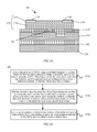
FIG. 17 is schematic diagrams of a semiconductor device at different stages in the method 400. As shown in FIG. 17, SOI includes a silicon substrate 510, a first dielectric layer 520, and a silicon layer 540.
In S410, a waveguide is produced in the silicon layer 540 of the SOI, for example, a ridge waveguide is produced, as shown in figure a in FIG. 17.
In S420, a second dielectric layer 550 is formed on the silicon layer 540 having the waveguide.
In S430, the second dielectric layer 550 is etched using a patterned template 590.
Optionally, the patterned template 590 is a porous alumina membrane or a photoresist after exposure to extreme ultraviolet and development. Before etching, a partial region of the patterned template 590 may be sheltered using a photoresist, where a region that is not sheltered by the photoresist corresponds to a position of the waveguide (as shown in figure b in FIG. 17).
The second dielectric layer 550 is etched, to expose the silicon layer 540, and form a window 551 on the second dielectric layer 550 (as shown in figure c in FIG. 17).
Because the patterned template 590 exerts a shadow effect on an etched beam current, a bottom horizontal size of the window 551 formed on the second dielectric layer 550 is less than a top horizontal size of the window 551. Therefore, a relatively small window may be formed in the second dielectric layer 550 by controlling a size of a window of the patterned template 590, for example, a window whose bottom horizontal size is not greater than 20 nm is formed.
Next, the photoresist and the patterned template 590 are removed.
In S440, a semiconductor material is selectively grown in the window 551 of the second dielectric layer 550 so that a buffer layer is formed first, and then the semiconductor material continues to be grown in the buffer layer so that a semiconductor layer 530 is obtained (as shown in figure d in FIG. 17).
Preferably, the semiconductor material is a III-V semiconductor material, which, for example, may be one or more of the following: aluminium phosphide (AlP), gallium phosphide (GaP), indium phosphide (InP), aluminium arsenide (AlAs), gallium arsenide (GaAs), indium arsenide (InAs), aluminium antimonide (AlSb), gallium antimonide (GaSb), indium antimonide (InSb), aluminium nitride (AlN), gallium nitride (GaN), indium nitride (InN), and ternary and quaternary compounds thereof.
Optionally, the semiconductor material may further include a preset quantity of doped materials.
Because a window whose bottom horizontal size is not greater than 20 nm may be formed in a dielectric layer according to the method for producing a semiconductor device in this embodiment of the present disclosure, a III-V semiconductor material in a semiconductor device produced using the method for producing a semiconductor device in this embodiment of the present disclosure has no threading dislocations. Therefore, a semiconductor device with relatively high performance can be produced according to the method for producing a semiconductor device in this embodiment of the present disclosure.
According to the method 400 for producing a semiconductor device in this embodiment of the present disclosure, the semiconductor device 200 in the foregoing embodiment of the present disclosure can be produced, and furthermore, with reference to the specific structure of the laser, the optical amplifier, the photodetector, or the transistor provided in the foregoing embodiment, a corresponding semiconductor device can be produced.
It should be understood that sequence numbers of the foregoing processes do not mean execution sequences in various embodiments of the present disclosure. The execution sequences of the processes should be determined according to functions and internal logic of the processes, and should not be construed as any limitation on the implementation processes of the embodiments of the present disclosure.
A person of ordinary skill in the art may be aware that, in combination with the examples described in the embodiments disclosed in this specification, units and algorithm steps may be implemented by electronic hardware, computer software, or a combination thereof. To clearly describe the interchangeability between the hardware and the software, the foregoing has generally described compositions and steps of each example according to functions. Whether the functions are performed by hardware or software depends on particular applications and design constraint conditions of the technical solutions. A person skilled in the art may use different methods to implement the described functions for each particular application, but it should not be considered that the implementation goes beyond the scope of the present disclosure.
It may be clearly understood by a person skilled in the art that, for the purpose of convenient and brief description, for a detailed working process of the foregoing system, apparatus, and unit, reference may be made to a corresponding process in the foregoing method embodiments, and details are not described herein again.
In the several embodiments provided in the present application, it should be understood that the disclosed system, apparatus, and method may be implemented in other manners. For example, the described apparatus embodiment is merely exemplary. For example, the unit division is merely logical function division and may be other division in an embodiment of implementation. For example, a plurality of units or components may be combined or integrated into another system, or some features may be ignored or not performed. In addition, the displayed or discussed mutual couplings or direct couplings or communication connections may be implemented through some interfaces. The indirect couplings or communication connections between the apparatuses or units may be implemented in electronic, mechanical, or other forms.
The units described as separate parts may or may not be physically separate, and parts displayed as units may or may not be physical units, may be located in one position, or may be distributed on a plurality of network units. A part or all of the units may be selected according to actual needs to achieve the objectives of the solutions of the embodiments of the present disclosure.
In addition, functional units in the embodiments of the present disclosure may be integrated into one processing unit, or each of the units may exist alone physically, or two or more units are integrated into one unit. The integrated unit may be implemented in a form of hardware, or may be implemented in a form of a software functional unit.
When the integrated unit is implemented in the form of a software functional unit and sold or used as an independent product, the integrated unit may be stored in a computer-readable storage medium. Based on such an understanding, the technical solutions of the present disclosure essentially, or the part contributing to the prior art, or all or a part of the technical solutions may be implemented in the form of a software product. The software product is stored in a storage medium and includes several instructions for instructing a computer device (which may be a personal computer, a server, or a network device) to perform all or a part of the steps of the methods described in the embodiments of the present disclosure. The foregoing storage medium includes any medium that can store program code, such as a universal serial bus (USB) flash drive, a removable hard disk, a read-only memory (ROM), a random access memory (RAM), a magnetic disk, or an optical disc.
The foregoing descriptions are merely specific embodiments of the present disclosure, but are not intended to limit the protection scope of the present disclosure. Any modification or replacement readily figured out by a person skilled in the art within the technical scope disclosed in the present disclosure shall fall within the protection scope of the present disclosure. Therefore, the protection scope of the present disclosure shall be subject to the protection scope of the claims.

Claims (7)

What is claimed is:
1. A method for producing a semiconductor device, comprising:
etching a silicon layer of silicon on insulator (SOI) using a patterned template as a mask, the SOI comprising a silicon substrate, a dielectric layer on the silicon substrate, and the silicon layer on the dielectric layer, a first window of the silicon layer being etched to expose the dielectric layer, and a bottom horizontal size of the first window being less than a top horizontal size of the first window;
etching the dielectric layer using the silicon layer having the first window as a template, a second window of the dielectric layer being etched to expose the silicon substrate, the second window of the dielectric layer being shaped to limit a size of contact surface exposed over the silicon substrate, and a bottom horizontal size of the second window being less than a top horizontal size of the second windows; and
growing a semiconductor material in the second window of the dielectric layer to form a buffer layer, the semiconductor material being further grown on the buffer layer to obtain a semiconductor layer, the limited size of the contact surface to reduce threading dislocations of the semiconductor material within the second window of the dielectric layer, the size of the contact surface being based on the bottom horizontal size of the second window of the dielectric layer, and the bottom horizontal size of the second window not being grater than twenty nanometers (nm).
2. The method of claim 1, wherein the semiconductor material is a III-V semiconductor material.
3. The method of claim 1, further comprising sheltering a partial region of the patterned template using a photoresist so that the silicon layer under the sheltered region is not etched.
4. The method of claim 3, further comprising producing a waveguide in the silicon layer that is not etched.
5. A non-transitory computer readable medium, comprising computer program code, which, when executed by a computer unit, will cause the computer unit to:
etch a silicon layer of silicon on insulator (SOI) using a patterned template as a mask, the SOI comprising a silicon substrate, a dielectric layer on the silicon substrate, and the silicon layer on the dielectric layer, a first window of the silicon layer being etched to expose the dielectric layer, and a bottom horizontal size of the first window being less than a top horizontal size of the first window;
etch the dielectric layer using the silicon layer having the first window as a template, a second window of the dielectric layer being etched to expose the silicon substrate, the window of the dielectric layer being shaped to limit a size of contact surface exposed over the silicon substrate, and a bottom horizontal size of the second window being less than a top horizontal size of the second window; and
grow a semiconductor material in the second window of the dielectric layer to form a buffer layer, the semiconductor material being further grown on the buffer layer to obtain a semiconductor layer, the limited size of the contact surface to reduce threading dislocations of the semiconductor material within the second window of the dielectric layer, the size of the contact surface being based on the bottom horizontal size of the second window of the dielectric layer, and the bottom horizontal size of the second window not being greater than twenty nanometers (nm).
6. The computer readable medium of the claim 5, the computer program code further causing the computer unit to shelter a partial region of the patterned template using a photoresist so that the silicon layer under the sheltered region is not etched.
7. The computer readable medium of the claim 6, the computer program code further causing the computer unit to produce a waveguide in the silicon layer that is not etched.
US15/975,496 2013-12-20 2018-05-09 Method for reducing threading dislocation of semiconductor device Active US10234629B2 (en)

Priority Applications (1)

Application Number Priority Date Filing Date Title
US15/975,496 US10234629B2 (en) 2013-12-20 2018-05-09 Method for reducing threading dislocation of semiconductor device

Applications Claiming Priority (3)

Application Number Priority Date Filing Date Title
PCT/CN2013/090099 WO2015089826A1 (en) 2013-12-20 2013-12-20 Semiconductor device and method for manufacturing same
US15/186,681 US20160291248A1 (en) 2013-12-20 2016-06-20 Semiconductor device and method for producing semiconductor device
US15/975,496 US10234629B2 (en) 2013-12-20 2018-05-09 Method for reducing threading dislocation of semiconductor device

Related Parent Applications (1)

Application Number Title Priority Date Filing Date
US15/186,681 Division US20160291248A1 (en) 2013-12-20 2016-06-20 Semiconductor device and method for producing semiconductor device

Publications (2)

Publication Number Publication Date
US20180259708A1 US20180259708A1 (en) 2018-09-13
US10234629B2 true US10234629B2 (en) 2019-03-19

Family

ID=53401994

Family Applications (2)

Application Number Title Priority Date Filing Date
US15/186,681 Abandoned US20160291248A1 (en) 2013-12-20 2016-06-20 Semiconductor device and method for producing semiconductor device
US15/975,496 Active US10234629B2 (en) 2013-12-20 2018-05-09 Method for reducing threading dislocation of semiconductor device

Family Applications Before (1)

Application Number Title Priority Date Filing Date
US15/186,681 Abandoned US20160291248A1 (en) 2013-12-20 2016-06-20 Semiconductor device and method for producing semiconductor device

Country Status (6)

Country Link
US (2) US20160291248A1 (en)
EP (2) EP3070751A4 (en)
JP (1) JP2017511596A (en)
KR (1) KR20160089519A (en)
CN (2) CN105264674B (en)
WO (1) WO2015089826A1 (en)

Families Citing this family (15)

* Cited by examiner, † Cited by third party
Publication number Priority date Publication date Assignee Title
FR3060772B1 (en) * 2016-12-20 2022-12-30 Thales Sa OPTIMIZED INTEGRATED PHOTONIC CIRCUIT
CN108054182B (en) * 2017-12-19 2024-04-12 苏州矩阵光电有限公司 Compound semiconductor silicon-based hybrid device and preparation method thereof
US11257672B2 (en) * 2018-05-14 2022-02-22 Globalfoundries U.S. Inc. Semiconductor devices including active regions in RAM areas with deposition determined pitch
JP7139960B2 (en) * 2019-01-10 2022-09-21 株式会社デンソー semiconductor equipment
CN112186050A (en) * 2019-07-04 2021-01-05 上海新微技术研发中心有限公司 III-V/Si heterostructure based on wafer bonding technology and integration method
GB2586889B (en) * 2019-08-26 2022-11-02 Rockley Photonics Ltd Method of manufacturing a III-V based optoelectronic device
EP4022724A1 (en) * 2019-08-30 2022-07-06 Aalto University Foundation sr Waveguide amplifier
CN114981714A (en) 2019-11-15 2022-08-30 洛克利光子有限公司 Optoelectronic device and method of making the same
WO2021111521A1 (en) * 2019-12-03 2021-06-10 日本電信電話株式会社 Method for forming semiconductor layer
CN114171394B (en) * 2021-06-18 2025-04-11 李勇 Semiconductor device manufacturing method and semiconductor device
US12189181B2 (en) 2021-09-22 2025-01-07 Rockley Photonics Limited Optoelectronic device
CN114050199B (en) * 2021-11-03 2025-03-18 昆明物理研究所 An InSb2 planar focal plane detector chip and its preparation
US12345915B1 (en) * 2022-06-28 2025-07-01 Seagate Technology Llc Heterogeneous integration of active layers on a heat-assisted magnetic recording slider
US12511463B2 (en) 2022-08-31 2025-12-30 Apple Inc. Backside contacts for signal routing
CN116632652A (en) * 2023-05-19 2023-08-22 常州承芯半导体有限公司 Formation method of vertical cavity surface emitting laser

Citations (24)

* Cited by examiner, † Cited by third party
Publication number Priority date Publication date Assignee Title
US4806996A (en) 1986-04-10 1989-02-21 American Telephone And Telegraph Company, At&T Bell Laboratories Dislocation-free epitaxial layer on a lattice-mismatched porous or otherwise submicron patterned single crystal substrate
JPH10170773A (en) 1996-12-13 1998-06-26 Kyocera Corp Method of manufacturing optical device mounting substrate and optical module
JPH1197796A (en) 1997-07-24 1999-04-09 Samsung Electron Co Ltd III-V compound surface emitting laser and method of manufacturing the same
US6461935B2 (en) * 1999-01-14 2002-10-08 Mitsubishi Denki Kabushiki Kaisha Method of manufacturing trench-shaped isolator
CN1445986A (en) 2002-03-18 2003-10-01 夏普株式会社 Display device and its manufacturing method
US6730588B1 (en) * 2001-12-20 2004-05-04 Lsi Logic Corporation Method of forming SiGe gate electrode
EP1522612A1 (en) 2003-05-08 2005-04-13 Sumitomo Electric Industries, Ltd. Iii-v compound semiconductor crystal and method for production thereof
US7029959B1 (en) * 2003-05-06 2006-04-18 Advanced Micro Devices, Inc. Source and drain protection and stringer-free gate formation in semiconductor devices
KR20060077807A (en) 2004-12-31 2006-07-05 엘지전자 주식회사 Lateral grown light emitting diodes and method of manufacturing the same
CN1983656A (en) 2005-12-15 2007-06-20 Lg电子株式会社 Light emitting diode with vertical structure and manufacturing method thereof
US20080153267A1 (en) 2006-12-21 2008-06-26 Commissariat A L'energie Atomique Method for manufacturing a soi substrate associating silicon based areas and gaas based areas
US20080187018A1 (en) * 2006-10-19 2008-08-07 Amberwave Systems Corporation Distributed feedback lasers formed via aspect ratio trapping
US7638842B2 (en) 2005-09-07 2009-12-29 Amberwave Systems Corporation Lattice-mismatched semiconductor structures on insulators
US7812357B2 (en) * 2005-12-15 2010-10-12 Lg Electronics Inc. LED having vertical structure and method for fabricating the same
JP2010536170A (en) 2007-08-08 2010-11-25 エージェンシー フォー サイエンス,テクノロジー アンド リサーチ Semiconductor structure and manufacturing method
US7893798B2 (en) * 2007-05-09 2011-02-22 Innovative Micro Technology Dual substrate MEMS plate switch and method of manufacture
CN102332423A (en) 2011-05-25 2012-01-25 湖南红太阳光电科技有限公司 Process for reducing chemical-mechanical polishing crack on buried layer cavity silicon-on-insulator (SOI) wafer
US20120028444A1 (en) * 2010-07-29 2012-02-02 Taiwan Semiconductor Manufacturing Company, Ltd. Defect-free hetero-epitaxy of lattice mismatched semiconductors
US20120270378A1 (en) 2009-10-31 2012-10-25 Gabriel Kittler Method for Producing Silicon Semiconductor Wafers Comprising a Layer for Integrating III-V Semiconductor Components
CN103390698A (en) 2012-05-08 2013-11-13 华夏光股份有限公司 Light-emitting diode and manufacturing method thereof
US20150262818A1 (en) * 2014-03-12 2015-09-17 International Business Machines Corporation Planar iii-v field effect transistor (fet) on dielectric layer
US9704958B1 (en) * 2015-12-18 2017-07-11 International Business Machines Corporation III-V field effect transistor on a dielectric layer
US9837302B1 (en) * 2016-08-26 2017-12-05 Qualcomm Incorporated Methods of forming a device having semiconductor devices on two sides of a buried dielectric layer
US10090409B2 (en) * 2016-09-28 2018-10-02 Monolithic Power Systems, Inc. Method for fabricating LDMOS with self-aligned body

Family Cites Families (4)

* Cited by examiner, † Cited by third party
Publication number Priority date Publication date Assignee Title
US187018A (en) * 1877-02-06 Improvement in harrows
WO2010038461A1 (en) * 2008-10-02 2010-04-08 住友化学株式会社 Semiconductor substrate, electronic device and method for manufacturing semiconductor substrate
CN102107852B (en) * 2009-12-24 2013-05-22 中国科学院微电子研究所 Semiconductor nanostructures and fabrication methods and their applications
CN102882129A (en) * 2012-10-25 2013-01-16 中国科学院半导体研究所 Method for preparing multi-wavelength silica-based hybrid laser array by changing width of silicon waveguide

Patent Citations (31)

* Cited by examiner, † Cited by third party
Publication number Priority date Publication date Assignee Title
US4806996A (en) 1986-04-10 1989-02-21 American Telephone And Telegraph Company, At&T Bell Laboratories Dislocation-free epitaxial layer on a lattice-mismatched porous or otherwise submicron patterned single crystal substrate
JPH10170773A (en) 1996-12-13 1998-06-26 Kyocera Corp Method of manufacturing optical device mounting substrate and optical module
JPH1197796A (en) 1997-07-24 1999-04-09 Samsung Electron Co Ltd III-V compound surface emitting laser and method of manufacturing the same
US6306672B1 (en) * 1997-07-24 2001-10-23 Samsung Electronics Co., Ltd. Group III-V complex vertical cavity surface emitting laser diode and method for manufacturing the same
US6461935B2 (en) * 1999-01-14 2002-10-08 Mitsubishi Denki Kabushiki Kaisha Method of manufacturing trench-shaped isolator
US6730588B1 (en) * 2001-12-20 2004-05-04 Lsi Logic Corporation Method of forming SiGe gate electrode
US7309880B2 (en) 2002-03-18 2007-12-18 Sharp Kabushiki Kaisha Display apparatus and method for producing the same
CN1445986A (en) 2002-03-18 2003-10-01 夏普株式会社 Display device and its manufacturing method
US7029959B1 (en) * 2003-05-06 2006-04-18 Advanced Micro Devices, Inc. Source and drain protection and stringer-free gate formation in semiconductor devices
CN101071794A (en) 2003-05-08 2007-11-14 住友电气工业株式会社 III-V crystal and production method
US7297625B2 (en) 2003-05-08 2007-11-20 Sumitomo Electric Industries, Ltd. Group III-V crystal and manufacturing method thereof
EP1522612A1 (en) 2003-05-08 2005-04-13 Sumitomo Electric Industries, Ltd. Iii-v compound semiconductor crystal and method for production thereof
KR20060077807A (en) 2004-12-31 2006-07-05 엘지전자 주식회사 Lateral grown light emitting diodes and method of manufacturing the same
US7638842B2 (en) 2005-09-07 2009-12-29 Amberwave Systems Corporation Lattice-mismatched semiconductor structures on insulators
CN1983656A (en) 2005-12-15 2007-06-20 Lg电子株式会社 Light emitting diode with vertical structure and manufacturing method thereof
US7812357B2 (en) * 2005-12-15 2010-10-12 Lg Electronics Inc. LED having vertical structure and method for fabricating the same
US8502263B2 (en) 2006-10-19 2013-08-06 Taiwan Semiconductor Manufacturing Company, Ltd. Light-emitter-based devices with lattice-mismatched semiconductor structures
US20080187018A1 (en) * 2006-10-19 2008-08-07 Amberwave Systems Corporation Distributed feedback lasers formed via aspect ratio trapping
US20080153267A1 (en) 2006-12-21 2008-06-26 Commissariat A L'energie Atomique Method for manufacturing a soi substrate associating silicon based areas and gaas based areas
JP2008166776A (en) 2006-12-21 2008-07-17 Commiss Energ Atom Method for manufacturing an SOI substrate associating a silicon-based region and a GaAs-based region
US7893798B2 (en) * 2007-05-09 2011-02-22 Innovative Micro Technology Dual substrate MEMS plate switch and method of manufacture
JP2010536170A (en) 2007-08-08 2010-11-25 エージェンシー フォー サイエンス,テクノロジー アンド リサーチ Semiconductor structure and manufacturing method
US20110084308A1 (en) * 2007-08-08 2011-04-14 Ter-Hoe Loh Semiconductor arrangement and a method for manufacturing the same
US20120270378A1 (en) 2009-10-31 2012-10-25 Gabriel Kittler Method for Producing Silicon Semiconductor Wafers Comprising a Layer for Integrating III-V Semiconductor Components
US20120028444A1 (en) * 2010-07-29 2012-02-02 Taiwan Semiconductor Manufacturing Company, Ltd. Defect-free hetero-epitaxy of lattice mismatched semiconductors
CN102332423A (en) 2011-05-25 2012-01-25 湖南红太阳光电科技有限公司 Process for reducing chemical-mechanical polishing crack on buried layer cavity silicon-on-insulator (SOI) wafer
CN103390698A (en) 2012-05-08 2013-11-13 华夏光股份有限公司 Light-emitting diode and manufacturing method thereof
US20150262818A1 (en) * 2014-03-12 2015-09-17 International Business Machines Corporation Planar iii-v field effect transistor (fet) on dielectric layer
US9704958B1 (en) * 2015-12-18 2017-07-11 International Business Machines Corporation III-V field effect transistor on a dielectric layer
US9837302B1 (en) * 2016-08-26 2017-12-05 Qualcomm Incorporated Methods of forming a device having semiconductor devices on two sides of a buried dielectric layer
US10090409B2 (en) * 2016-09-28 2018-10-02 Monolithic Power Systems, Inc. Method for fabricating LDMOS with self-aligned body

Non-Patent Citations (17)

* Cited by examiner, † Cited by third party
Title
Foreign Communication From a Counterpart Application, Chinese Application No. 201380004030.3, Chinese Office Action dated Mar. 1, 2017, 4 pages.
Foreign Communication From a Counterpart Application, Chinese Application No. 2013800040303, Chinese Search Report dated Feb. 21, 2017, 2 pages.
Foreign Communication From a Counterpart Application, European Application No. 13899857.0, Extended European Search Report dated Dec. 9, 2016, 7 pages.
Foreign Communication From a Counterpart Application, European Application No. 18160118.8, Extended European Search Report dated Dec. 13, 2018, 7 pages.
Foreign Communication From a Counterpart Application, Japanese Application No. 2016-541187, English Translation of Japanese Office Action dated Sep. 12, 2017, 5 pages.
Foreign Communication From a Counterpart Application, Japanese Application No. 2016-541187, Japanese Office Action dated Sep. 12, 2017, 5 pages.
Foreign Communication From a Counterpart Application, Korean Application No. 10-2016-7017473, English Translation of Korean Office Action dated Mar. 22, 2018, 6 pages.
Foreign Communication From a Counterpart Application, Korean Application No. 10-2016-7017473, Korean Office Action dated Mar. 22, 2018, 8 pages.
Foreign Communication From a Counterpart Application, PCT Application No. PCT/CN2013/090099, English Translation of International Search Report dated Sep. 17, 2014, 2 pages.
Foreign Communication From a Counterpart Application, PCT Application No. PCT/CN2013/090099, English Translation of Written Opinion dated Sep. 17, 2014, 5 pages.
Huangfu, Y., et al., "Heteroepitaxy of Ge on Si(001) with pits and windows transferred from free-standing porous alumina mask," IOP Publishing, Nanotechnology 24 (2013) 185302, Apr. 11, 2013, 8 pages.
KATSUHIRO TOMIOKA ; TOMOTAKA TANAKA ; SHINJIRO HARA ; KENJI HIRUMA ; TAKASHI FUKUI: "III V Nanowires on Si Substrate: Selective-Area Growth and Device Applications", IEEE JOURNAL OF SELECTED TOPICS IN QUANTUM ELECTRONICS., IEEE SERVICE CENTER, PISCATAWAY, NJ., US, vol. 17, no. 4, 1 July 2011 (2011-07-01), US, pages 1112 - 1129, XP011386487, ISSN: 1077-260X, DOI: 10.1109/JSTQE.2010.2068280
Machine Translation and Abstract of Chinese Publication No. CN102332423, Jan. 25, 2012, 11 pages.
Machine Translation and Abstract of Chinese Publication No. CN103390698, Nov. 13, 2013, 8 pages.
Machine Translation and Abstract of Japanese Publication No. JPH10170773, Jun. 26, 1998, 15 pages.
Machine Translation and Abstract of Korean Publication No. KR20060077807, Jul. 5, 2006, 5 pages.
Tomioka, K, et al., "III-V Nanowires on Si Substrate: Selective-Area Growth and Device Applications," XP11386487, IEEE Journal of Selected Topics in Quantum Electronics, vol. 17, No. 4, Jul. 1, 2011, pp. 1112-1129.

Also Published As

Publication number Publication date
US20160291248A1 (en) 2016-10-06
KR20160089519A (en) 2016-07-27
EP3070751A1 (en) 2016-09-21
JP2017511596A (en) 2017-04-20
CN109860022A (en) 2019-06-07
EP3070751A4 (en) 2017-01-11
CN105264674A (en) 2016-01-20
WO2015089826A1 (en) 2015-06-25
US20180259708A1 (en) 2018-09-13
EP3428957B1 (en) 2021-12-08
EP3428957A1 (en) 2019-01-16
CN105264674B (en) 2019-01-18
CN109860022B (en) 2022-09-23

Similar Documents

Publication Publication Date Title
US10234629B2 (en) Method for reducing threading dislocation of semiconductor device
US8278687B2 (en) Semiconductor heterostructures to reduce short channel effects
CN106033724A (en) III-family nitride reinforced HEMT and preparation method thereof
US10056251B2 (en) Hetero-integration of III-N material on silicon
JP2014204125A (en) Substrate structure and semiconductor element including the same
JP2013110160A (en) Semiconductor nanodevice
US20130105946A1 (en) Semiconductor device including group iii-v compound semiconductor layer, and method of manufacturing the semiconductor device
TW202018770A (en) Method for manufacturing semiconductor arrangement
US9589791B2 (en) Compound finFET device including oxidized III-V fin isolator
JP2015088756A (en) Substrate structure, cmos device including the same, and method of manufacturing the same
CN102107852A (en) Semiconductor nanostructures and fabrication methods and their applications
JPH06342811A (en) Field effect transistor and its manufacture
CN109801930B (en) Heterogeneous semiconductor structure and method of manufacturing the same
US20150129926A1 (en) Semiconductor device and manufacturing method thereof
US11164939B2 (en) Tunnel field-effect transistor and method for forming the same
US11728448B2 (en) Fabrication of a semiconductor device including a quantum dot structure
JP5367637B2 (en) Semiconductor element
WO2018094711A1 (en) Tunnel field effect transistor, and manufacturing method thereof
CN106328519A (en) Semiconductor device forming method
CN106876460B (en) The forming method of transistor with dissymmetrical structure
CN220753434U (en) GaN-based PN junction gate p-channel device
JP2005150136A (en) Method for manufacturing a semiconductor device comprising a nitride compound
CN119069350A (en) Self-aligned structure gallium nitride p-channel enhancement device and preparation method
CN118508237A (en) A method for lateral selective heteroepitaxial high-quality buried quantum well on SOI
CN105576012A (en) Semiconductor device, and preparation method and application thereof

Legal Events

Date Code Title Description
AS Assignment

Owner name: HUAWEI TECHNOLOGIES CO., LTD., CHINA

Free format text: ASSIGNMENT OF ASSIGNORS INTEREST;ASSIGNOR:HUANGFU, YOURUI;REEL/FRAME:045757/0517

Effective date: 20160722

FEPP Fee payment procedure

Free format text: ENTITY STATUS SET TO UNDISCOUNTED (ORIGINAL EVENT CODE: BIG.); ENTITY STATUS OF PATENT OWNER: LARGE ENTITY

STCF Information on status: patent grant

Free format text: PATENTED CASE

MAFP Maintenance fee payment

Free format text: PAYMENT OF MAINTENANCE FEE, 4TH YEAR, LARGE ENTITY (ORIGINAL EVENT CODE: M1551); ENTITY STATUS OF PATENT OWNER: LARGE ENTITY

Year of fee payment: 4