US10184454B2 - Wind turbine for generating electricity with naval technology - Google Patents
Wind turbine for generating electricity with naval technology Download PDFInfo
- Publication number
- US10184454B2 US10184454B2 US14/773,158 US201414773158A US10184454B2 US 10184454 B2 US10184454 B2 US 10184454B2 US 201414773158 A US201414773158 A US 201414773158A US 10184454 B2 US10184454 B2 US 10184454B2
- Authority
- US
- United States
- Prior art keywords
- vertical shaft
- tower
- wind
- wind turbine
- rotor
- Prior art date
- Legal status (The legal status is an assumption and is not a legal conclusion. Google has not performed a legal analysis and makes no representation as to the accuracy of the status listed.)
- Active, expires
Links
- 238000005516 engineering process Methods 0.000 title abstract description 15
- 230000005611 electricity Effects 0.000 title abstract 2
- 230000005540 biological transmission Effects 0.000 claims abstract description 55
- 230000009467 reduction Effects 0.000 claims abstract description 7
- 230000008878 coupling Effects 0.000 claims description 8
- 238000010168 coupling process Methods 0.000 claims description 8
- 238000005859 coupling reaction Methods 0.000 claims description 8
- 238000001816 cooling Methods 0.000 claims description 5
- 230000005405 multipole Effects 0.000 claims description 5
- 238000005057 refrigeration Methods 0.000 claims description 5
- 239000012530 fluid Substances 0.000 claims description 4
- 230000008859 change Effects 0.000 claims description 3
- 230000006698 induction Effects 0.000 claims description 3
- 238000005086 pumping Methods 0.000 claims description 3
- 230000004308 accommodation Effects 0.000 claims description 2
- 230000003213 activating effect Effects 0.000 claims description 2
- 230000005674 electromagnetic induction Effects 0.000 claims description 2
- 239000010687 lubricating oil Substances 0.000 claims description 2
- 230000000694 effects Effects 0.000 claims 1
- 238000002955 isolation Methods 0.000 claims 1
- 238000005259 measurement Methods 0.000 claims 1
- 238000004891 communication Methods 0.000 abstract description 10
- 230000005570 vertical transmission Effects 0.000 abstract description 6
- 238000012423 maintenance Methods 0.000 abstract description 5
- 239000000463 material Substances 0.000 abstract description 3
- 229940112112 capex Drugs 0.000 abstract description 2
- FEBLZLNTKCEFIT-VSXGLTOVSA-N fluocinolone acetonide Chemical compound C1([C@@H](F)C2)=CC(=O)C=C[C@]1(C)[C@]1(F)[C@@H]2[C@@H]2C[C@H]3OC(C)(C)O[C@@]3(C(=O)CO)[C@@]2(C)C[C@@H]1O FEBLZLNTKCEFIT-VSXGLTOVSA-N 0.000 abstract description 2
- 230000008602 contraction Effects 0.000 abstract 1
- 230000009471 action Effects 0.000 description 10
- 230000008901 benefit Effects 0.000 description 8
- 238000010248 power generation Methods 0.000 description 7
- 238000013461 design Methods 0.000 description 6
- XLYOFNOQVPJJNP-UHFFFAOYSA-N water Substances O XLYOFNOQVPJJNP-UHFFFAOYSA-N 0.000 description 4
- 238000005452 bending Methods 0.000 description 3
- 230000005672 electromagnetic field Effects 0.000 description 3
- 230000009347 mechanical transmission Effects 0.000 description 3
- 241001494479 Pecora Species 0.000 description 2
- 239000000919 ceramic Substances 0.000 description 2
- 230000006835 compression Effects 0.000 description 2
- 238000007906 compression Methods 0.000 description 2
- 238000011161 development Methods 0.000 description 2
- 210000003746 feather Anatomy 0.000 description 2
- 230000002459 sustained effect Effects 0.000 description 2
- OKTJSMMVPCPJKN-UHFFFAOYSA-N Carbon Chemical compound [C] OKTJSMMVPCPJKN-UHFFFAOYSA-N 0.000 description 1
- 229910052581 Si3N4 Inorganic materials 0.000 description 1
- 238000013473 artificial intelligence Methods 0.000 description 1
- 239000003990 capacitor Substances 0.000 description 1
- 229910052799 carbon Inorganic materials 0.000 description 1
- 239000012141 concentrate Substances 0.000 description 1
- 239000012809 cooling fluid Substances 0.000 description 1
- 230000002349 favourable effect Effects 0.000 description 1
- 238000001914 filtration Methods 0.000 description 1
- 239000005431 greenhouse gas Substances 0.000 description 1
- 238000010438 heat treatment Methods 0.000 description 1
- 238000009434 installation Methods 0.000 description 1
- 230000001050 lubricating effect Effects 0.000 description 1
- 239000011159 matrix material Substances 0.000 description 1
- 229910052751 metal Inorganic materials 0.000 description 1
- 239000002184 metal Substances 0.000 description 1
- 150000002739 metals Chemical class 0.000 description 1
- 238000000034 method Methods 0.000 description 1
- 230000000116 mitigating effect Effects 0.000 description 1
- 230000003472 neutralizing effect Effects 0.000 description 1
- 239000003921 oil Substances 0.000 description 1
- 238000010422 painting Methods 0.000 description 1
- 230000035515 penetration Effects 0.000 description 1
- 230000000737 periodic effect Effects 0.000 description 1
- 238000001228 spectrum Methods 0.000 description 1
- 230000003068 static effect Effects 0.000 description 1
- 230000004083 survival effect Effects 0.000 description 1
- 238000012546 transfer Methods 0.000 description 1
- 230000007704 transition Effects 0.000 description 1
- 230000001960 triggered effect Effects 0.000 description 1
- 238000009423 ventilation Methods 0.000 description 1
- 238000003466 welding Methods 0.000 description 1
Images


Classifications
-
- F—MECHANICAL ENGINEERING; LIGHTING; HEATING; WEAPONS; BLASTING
- F03—MACHINES OR ENGINES FOR LIQUIDS; WIND, SPRING, OR WEIGHT MOTORS; PRODUCING MECHANICAL POWER OR A REACTIVE PROPULSIVE THRUST, NOT OTHERWISE PROVIDED FOR
- F03D—WIND MOTORS
- F03D1/00—Wind motors with rotation axis substantially parallel to the air flow entering the rotor
- F03D1/06—Rotors
- F03D1/065—Rotors characterised by their construction elements
- F03D1/0658—Arrangements for fixing wind-engaging parts to a hub
-
- F03D11/02—
-
- F—MECHANICAL ENGINEERING; LIGHTING; HEATING; WEAPONS; BLASTING
- F03—MACHINES OR ENGINES FOR LIQUIDS; WIND, SPRING, OR WEIGHT MOTORS; PRODUCING MECHANICAL POWER OR A REACTIVE PROPULSIVE THRUST, NOT OTHERWISE PROVIDED FOR
- F03D—WIND MOTORS
- F03D1/00—Wind motors with rotation axis substantially parallel to the air flow entering the rotor
- F03D1/06—Rotors
-
- F—MECHANICAL ENGINEERING; LIGHTING; HEATING; WEAPONS; BLASTING
- F03—MACHINES OR ENGINES FOR LIQUIDS; WIND, SPRING, OR WEIGHT MOTORS; PRODUCING MECHANICAL POWER OR A REACTIVE PROPULSIVE THRUST, NOT OTHERWISE PROVIDED FOR
- F03D—WIND MOTORS
- F03D15/00—Transmission of mechanical power
-
- F—MECHANICAL ENGINEERING; LIGHTING; HEATING; WEAPONS; BLASTING
- F03—MACHINES OR ENGINES FOR LIQUIDS; WIND, SPRING, OR WEIGHT MOTORS; PRODUCING MECHANICAL POWER OR A REACTIVE PROPULSIVE THRUST, NOT OTHERWISE PROVIDED FOR
- F03D—WIND MOTORS
- F03D80/00—Details, components or accessories not provided for in groups F03D1/00 - F03D17/00
- F03D80/70—Bearing or lubricating arrangements
-
- F—MECHANICAL ENGINEERING; LIGHTING; HEATING; WEAPONS; BLASTING
- F03—MACHINES OR ENGINES FOR LIQUIDS; WIND, SPRING, OR WEIGHT MOTORS; PRODUCING MECHANICAL POWER OR A REACTIVE PROPULSIVE THRUST, NOT OTHERWISE PROVIDED FOR
- F03D—WIND MOTORS
- F03D80/00—Details, components or accessories not provided for in groups F03D1/00 - F03D17/00
- F03D80/80—Arrangement of components within nacelles or towers
- F03D80/88—Arrangement of components within nacelles or towers of mechanical components
-
- F—MECHANICAL ENGINEERING; LIGHTING; HEATING; WEAPONS; BLASTING
- F03—MACHINES OR ENGINES FOR LIQUIDS; WIND, SPRING, OR WEIGHT MOTORS; PRODUCING MECHANICAL POWER OR A REACTIVE PROPULSIVE THRUST, NOT OTHERWISE PROVIDED FOR
- F03D—WIND MOTORS
- F03D9/00—Adaptations of wind motors for special use; Combinations of wind motors with apparatus driven thereby; Wind motors specially adapted for installation in particular locations
- F03D9/20—Wind motors characterised by the driven apparatus
- F03D9/25—Wind motors characterised by the driven apparatus the apparatus being an electrical generator
- F03D9/255—Wind motors characterised by the driven apparatus the apparatus being an electrical generator connected to electrical distribution networks; Arrangements therefor
- F03D9/257—Wind motors characterised by the driven apparatus the apparatus being an electrical generator connected to electrical distribution networks; Arrangements therefor the wind motor being part of a wind farm
-
- F—MECHANICAL ENGINEERING; LIGHTING; HEATING; WEAPONS; BLASTING
- F03—MACHINES OR ENGINES FOR LIQUIDS; WIND, SPRING, OR WEIGHT MOTORS; PRODUCING MECHANICAL POWER OR A REACTIVE PROPULSIVE THRUST, NOT OTHERWISE PROVIDED FOR
- F03D—WIND MOTORS
- F03D80/00—Details, components or accessories not provided for in groups F03D1/00 - F03D17/00
- F03D80/60—Cooling or heating of wind motors
-
- F—MECHANICAL ENGINEERING; LIGHTING; HEATING; WEAPONS; BLASTING
- F03—MACHINES OR ENGINES FOR LIQUIDS; WIND, SPRING, OR WEIGHT MOTORS; PRODUCING MECHANICAL POWER OR A REACTIVE PROPULSIVE THRUST, NOT OTHERWISE PROVIDED FOR
- F03D—WIND MOTORS
- F03D9/00—Adaptations of wind motors for special use; Combinations of wind motors with apparatus driven thereby; Wind motors specially adapted for installation in particular locations
- F03D9/10—Combinations of wind motors with apparatus storing energy
- F03D9/11—Combinations of wind motors with apparatus storing energy storing electrical energy
-
- F—MECHANICAL ENGINEERING; LIGHTING; HEATING; WEAPONS; BLASTING
- F05—INDEXING SCHEMES RELATING TO ENGINES OR PUMPS IN VARIOUS SUBCLASSES OF CLASSES F01-F04
- F05B—INDEXING SCHEME RELATING TO WIND, SPRING, WEIGHT, INERTIA OR LIKE MOTORS, TO MACHINES OR ENGINES FOR LIQUIDS COVERED BY SUBCLASSES F03B, F03D AND F03G
- F05B2260/00—Function
- F05B2260/40—Transmission of power
- F05B2260/403—Transmission of power through the shape of the drive components
-
- Y—GENERAL TAGGING OF NEW TECHNOLOGICAL DEVELOPMENTS; GENERAL TAGGING OF CROSS-SECTIONAL TECHNOLOGIES SPANNING OVER SEVERAL SECTIONS OF THE IPC; TECHNICAL SUBJECTS COVERED BY FORMER USPC CROSS-REFERENCE ART COLLECTIONS [XRACs] AND DIGESTS
- Y02—TECHNOLOGIES OR APPLICATIONS FOR MITIGATION OR ADAPTATION AGAINST CLIMATE CHANGE
- Y02E—REDUCTION OF GREENHOUSE GAS [GHG] EMISSIONS, RELATED TO ENERGY GENERATION, TRANSMISSION OR DISTRIBUTION
- Y02E10/00—Energy generation through renewable energy sources
- Y02E10/70—Wind energy
- Y02E10/72—Wind turbines with rotation axis in wind direction
-
- Y02E10/721—
-
- Y02E10/726—
-
- Y—GENERAL TAGGING OF NEW TECHNOLOGICAL DEVELOPMENTS; GENERAL TAGGING OF CROSS-SECTIONAL TECHNOLOGIES SPANNING OVER SEVERAL SECTIONS OF THE IPC; TECHNICAL SUBJECTS COVERED BY FORMER USPC CROSS-REFERENCE ART COLLECTIONS [XRACs] AND DIGESTS
- Y02—TECHNOLOGIES OR APPLICATIONS FOR MITIGATION OR ADAPTATION AGAINST CLIMATE CHANGE
- Y02E—REDUCTION OF GREENHOUSE GAS [GHG] EMISSIONS, RELATED TO ENERGY GENERATION, TRANSMISSION OR DISTRIBUTION
- Y02E70/00—Other energy conversion or management systems reducing GHG emissions
- Y02E70/30—Systems combining energy storage with energy generation of non-fossil origin
Definitions
- the present invention is about a large-sized wind turbine for generation of electric power.
- the main objective of this document is to present the technical provisions of a large-sized aerogenerator based on the innovative arrangement of its components.
- the power is the essential basic infrastructure for the human survival and development, and the wind power has the differential of being clean, renewable and with low cost.
- the technologies for clean and renewable power generation, such as wind can perform a relevant role in this transition.
- the use of wind power has globally grown in the last five years at very high rates, increasingly representing higher share in the Brazilian and the global energetic matrix.
- Another disadvantage of having the generator and different components used at more than 100 m height is the difficulty to perform periodic maintenance necessary for the good functioning of this kind of equipment, in addition to representing additional risk to the involved workers.
- the present invention was developed aiming at using latest technology innovative systems in wind equipment for generation of electric power, with the purpose to reduce the value of the installed power (installed MW) in a wind farm, proposing a wind turbine likely to be used in industrial application, quite different from the already known projects, which use vertical transmission along the tower and also transferred big part of the equipment traditionally housed in the Nacelle to the ground.
- the wind turbine for generation of electric power with naval technology object of the present invention, enables scale gain in the wind designs, thus allowing the increase of the turbine power, without corresponding increase of the whole structure due to the drastic reduction of materials in the Nacelle, in the tower, in the foundation, taking big part of the equipment to the tower base.
- this technology allows achieving higher power than those achieved in conventional wind turbines, with lower cost of installed MW.
- FIG. 1 a higher perspective view with detailing of the transmission of the wind turbine with naval technology.
- FIG. 2 a general view of the wind turbine in cross section.
- FIG. 3 a view of the wind farm with the air interface of the “Radio Tele Supervision Inter-communicator Spark” functioning.
- FIG. 4 a detailed lower view of the “YAW Drive System for Self-Locking Servo-positioner Spark”.
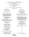
- FIG. 5 a basic functioning flow chart of the “YAW Drive System for Self-Locking Servo-positioner Spark”.
- FIG. 6 a cross section View with detailing of the bunker with direct drive generator.
- FIG. 7 a “shaft line” of a large-sized ship.
- FIG. 8 a general view of the transmission of a large-sized container ship with “motor shaft line” technology.
- the transmission of the wind turbine consists of: Support platforms ( 1 ) of the vertical shaft ( 6 ) along the tower over the harmonic points to neutralize the vibrations and the noises, shrinkage and expansion joint ( 2 ), that couples the upper transmission system H/Vst ( 3 ) to the vertical shaft ( 6 ), which adjusts the expansion and thermal shrinkage issues and the structural distortions due to the air elastic forces, upper transmission system H/Vst ( 3 ) with torque sensor (Horizontal/Vertical with coupled torque sensor), lower transmission system V/Hmvst ( 4 )—Vertical/Horizontal—with speed multiplication and torque sensor), upper brake disk ( 5 ) next to its hydraulic control, mechanical vertical shaft transmission ( 6 ) (Shaft line), which uses naval technology, a second set of disk brakes ( 7 )—Lower brake system—that are coupled to the transmission at the tower base, driven by hydraulic clamps, whose hydraulic control system is close to this system, propeller pitch control ( 8 ), main shaft ( 9
- FIG. 2 presents a general view of the wind turbine in cross section.
- An underground Bunker ( 11 ) can be seen there (on the ground), which is connected to a concrete foundation or “monopile”, axial bearing for the vertical shaft ( 12 ) sustaining, a diesel generating set ( 13 ), firefighting system ( 14 ), low friction couplings of the vertical shaft ( 15 ), rotor ( 16 ), Nacelle with YAW control ( 17 ), anemometric tower ( 18 ), antenna ( 19 ) of the “Tele supervision radio inter-communicator Spark”, refrigeration fluid cooling tower ( 20 ), control cabinet ( 21 ).
- FIG. 3 presents a view of the wind farm with the air interface of the “Tele supervision radio inter-communicator Spark” functioning.
- the air interface of the “Tele supervision radio inter-communicator Spark” consists of radio antennas ( 19 ) installed in each turbine, which communicate in among the other towers, these towers communicated with an information concentrating tower ( 28 ), that exchanges information with the control center ( 27 ), located in the control cabinet ( 21 ) in the Bunker, with a direct connection to the center ( 27 ) (point-to-point radio) and with one more redundancy, as well, using a radio equal to the turbines', the wind turbines in question allow the passage of a signal from the telecommunication operators (telephone, TV, AM and FM radio) ( 24 ), allowing the crossing of the radio signal ( 25 ) within the wind farm, the physical means of data exchange (data cables) consist of connections ( 26 ), which concentrate this physical means of data exchange until the radio center ( 27 ).
- the arrangement of the turbines is only illust
- FIG. 4 displays in detail the “YAW Drive System for Self-Locking Servo-positioner Spark”, which comprehends a YAW drive control system ( 29 ), electro-mechanical and/or hydraulic systems for locking ( 30 ), hydraulic brake systems ( 31 ), “shrinkage and expansion joint” ( 2 ).
- FIG. 5 presents the Flow chart of the “YAW Drive System for Self-Locking Servo-positioner Spark” consisted in basic logics of the system operation.
- the wind turbine with horizontal shaft and vertical transmission uses the force of the wind to drive an active Axial multi-blade rotor ( 16 ), which changes the pitch of such propellers (Hub with active propeller pitch control), and which communicates with a meteorological station close to the Rotor to use the wind better and brakes as well, taking the attack angle to zero degrees (propeller feather), or negative angle, to brake the turbine (force, opposite to the rotation direction).
- This rotor is fixed to a main shaft ( 9 ), which is supported by a reinforced Skid (main frame) to sustain the whole Rotor, and is provided with bearing housings with special bearings to neutralize the axial forces present in this region of the machine, and sustain the whole rotor assembly adequately. These bearings are provided with lubricating oil-pumping systems.
- a brake disc ( 5 ) (Upper braking system), driven by hydraulic clamps, whose upper hydraulic control system is fixed to the Skid (main frame).
- the Skid in question is provided with gearmotors (YAW Drive System) responsible for the control of the positioning of the whole upper structure, in a way to position the rotor perpendicularly to the wind incidence (there is front incidence of winds on the propellers on our machine (Upwind)).
- This Skid is fixed to a special big-sized bearing (this bearing is provided with a ring gear, which enables the gearmotors and their gear pinions to rotate the whole upper assembly mechanically), that in turn, couples the whole upper assembly to the wind turbine sustaining tower.
- the common name of this upper assembly between the rotor and the tower is called Nacelle ( 17 ), as mentioned in the beginning of this document, which houses all items mentioned above.
- grounding systems brushes, wire ropes, cables, etc.
- control cables electric feeding cables
- general sensors encoders (positioning sensors), rotor housing and nacelle housing fairing ( 17 )
- batteries capacitors
- appropriate firefighting system 14
- “tele supervision radio inter-communicator Spark” radio for communication among the turbine in the farm, which will be better explained here below
- guard light general lighting
- upper control center and anemometric station 18
- the rotor ( 16 ) is connected to a main shaft ( 9 ), and this shaft is connected to an upper transmission system H/Vst ( 3 ) with torque sensor (Horizontal/Vertical with coupled torque sensor).
- This transmission enables higher rotation torques from the horizontal direction to the Vertical direction.
- This transmission system H/Vst ( 3 ) is positioned in the Nacelle Skid ( 17 ) (Main frame), exactly in the upper center of the tower (in the center of the connection between the Nacelle ( 17 ) and the tower).
- This H/Vst transmission transmits the rotor torque to the vertical shaft (torque tube or Shaft line) at winds from 3 m/s, and the latter mechanically transmits the rotor power to the lower part of the tower to the lower transmission system V/Hmvst ( 4 ) (Horizontal/Vertical with speed multiplication and torque sensor), which in turn takes the transmission RMP to the perfect conditions for electric power generation, and is coupled to one or more generators ( 32 ), of adequate models for the torque curve of the machine(s) installed in the lower part of the tower or inside an underground Bunker ( 11 ) (on the ground), which is connected to concrete foundation or “monopile”, which will be further explained better.
- the vertical shaft ( 6 ) may also be connected to a Direct Drive system, which connects to a multi-pole generator in the tower base.
- the vertical shaft ( 6 ) is provided with naval technology known as “Motor Shaft Line”.
- Such shaft can transmit more than 100 MW power at more than 120 m distance.
- the present invention uses the naval engineering to develop this vertical shaft in the wind turbine tower, a fact, which has not been seen in this industry yet.
- Support platforms ( 1 ) are used along the tower, because as all dynamic devices, this vertical shaft ( 6 ) (Shaft line) causes vibrations, and therefore, there are harmonics, which shall be neutralized for the perfect functioning of a structure with this size.
- These support platforms ( 1 ) along the tower are strategically placed at harmonic points of the vertical shaft ( 6 ) (Shaft Line), because the tower is not static; as in a large-sized ship, the tower is subjected to different forces, such as, for example: air elastic, buckling and bending and torsion, among others. This is due to the wind loads on the tower itself and on the rotor, thus, these platforms are indispensable to neutralize the vibrations and the noises on the vertical shaft, phenomena, whose lack of control makes the design unfeasible.
- the support platforms ( 1 ) in question are not necessarily installed symmetrically far one from the other, because they will vary according to the harmonic points, RPM and the turbine power. Between platform ( 1 ) and the vertical shaft ( 6 ), there are low-friction couplings to reduce loss of these supports, which are of the hinge type, for fast and easy maintenance.
- This joint ( 2 ) also helps in the structural variances caused by the air elastic efforts on the structure.
- the Vertical shaft ( 6 ) is self-sustaining, because the whole weight of this structure is sustained by an axial bearing at the tower base, considering that it can also be an electromagnetic repulsion coupling, thus neutralizing the weight load pm the Nacelle ( 17 ) and at the other points of the tower structure. This point will be acoustically isolated at the tower base.
- the transmission of the power generated by the wind depends on the common functioning of all components of the wind turbine object of this invention, composed of a Main shaft ( 9 ), an upper transmission system H/Vst ( 3 ) (Horizontal/Vertical with torque sensor), which has a hydraulic brake disc ( 5 ) between these components, this transmission connects to the adjustable coupling system “expansion and shrinkage joint” ( 2 ), which works according to expansion, thermal shrinkage and possible structural movements (due to the air elastic efforts), connected to the Vertical shaft ( 6 ), which is provided with support platforms ( 1 ) to neutralize the harmonic vibrations and is self-sustaining to eliminate load on the structure, supported by an axial bearing in an acoustically isolated location, coupled to a lower transmission system V/Hmvst ( 4 ) (Vertical/horizontal with speed multiplication and torque sensor), which increases the rotation speed of the system, in order to keep the generator ( 32 ) in the best possible yield condition.
- H/Vst 3
- a second set of disc brakes (lower braking system) is coupled to the transmission at the tower base, driven by hydraulic clamps, whose hydraulic control system is situated close to this system.
- This transmission was developed to withstand all conditions of a wind turbine, such as, blow winds (sudden impact on the turbine), storms (very strong winds, rain and lightning bolts), constant winds and winds with variable direction.
- the brake electronic control center of this transmission sends information (signals) to the brake clamp control hydraulic systems, informing the braking intensity conditions, and perfectly controlling the deceleration ramp of the whole transmission safely under any condition that requires braking of the wind turbine in question.
- the position and the torque sensors coupled to the upper and the lower transmission send signals to the brake controls, which control the braking of the whole transmission safely, avoiding excessive impact on the Vertical shaft ( 6 ), and on the upper ( 3 ) and the lower ( 4 ) transmissions.
- the propeller pitch control also communicates with this system for the perfect balance of the whole system.
- This rotation force trends to rotate the whole Nacelle ( 17 ), in the direction opposite to the vertical shaft ( 6 ) movement.
- the Nacelle ( 17 ) in question is provided with gearmotors fixed to the Skid (Main Frame), responsible for the control of the positioning of the whole upper structure (YAW Drive), in order to position the rotor ( 16 ) perpendicularly to the wind incidence, reminding such movement might occur while the rotor is rotating.
- YAW Drive System for Self-Locking Servo-positioner Spark This system enables the azimuth control (positioning of the Nacelle ( 17 ) for the rotor to fall upon perpendicularly to the wind (YAW Drive system)), while the vertical shaft ( 6 ) applies a force opposite, or favorable, to the Nacelle ( 17 ) movement, for the rotor to be correctly positioned to the wind incidence.
- the rotor positioning in relation to the wind can be exemplified in the following way: if the vertical shaft is turned clockwise and the Nacelle has to turn to the right, the “YAW Drive System for Self-Locking Servo-positioner Spark” will position the Nacelle in favor to the vertical shaft movement and if the Nacelle has to turn to the left, the “YAW Drive System for Self-Locking Servo-positioner Spark” will position the Nacelle in direction opposite to the vertical shaft movement.
- One or more encoders will help in the execution of this task.
- the differential of the system proposed now is the electromechanical or hydraulic lock of the YAW control and the logics of operation of these components, as it can be seen on FIGS. 4 and 5 .
- the present invention proposes transfer of big part of the equipment traditionally housed in the Nacelle ( 1 ) to the ground (in case of onshore machines, but the turbines can also be offshore and the machine house can be situated close to the water level) building a machine house, containing all equipment necessary for the electric power generation:
- the whole structure of the machine house presented above can be situated next to the tower base or in an “Underground Bunker” ( 11 ), which is connected to concrete foundation or “monopile”.
- This concrete Bunker is under the ground level and all equipment are arranged conveniently spaced, distributed (correct division among components) in thermally controlled and acoustically isolated environments (room divisions can be contemplated).
- This Bunker will be provided with a draining system, which will not allow water penetration, ventilation system, anti-mold painting and conditions much more convenient for the workers.
- Bunker will not cause atmospheric turbulence in the wind farm, preserving the aerodynamic characteristics of the wind turbine in question, allowing the use of analysis software, which defines the turbine positioning in the wind farm; this is a great economic advantage, because we will be able to use already existing traditional software.
- the generators When the generators are installed on the Nacelle ( 17 ), on the top of the tower (as in the current wind turbines), they generate a big electromagnetic field, impeding the crossing of the radio communication systems. Thanks to the benefits proposed by the present invention (free Magnetic field); the wind turbine may be provided with a “tele supervision ratio inter-communicator system Spark”. This is a communication radio, which can be installed in each of the turbines in the farm, or in a remotely controlled center.
- This radio system enables all turbines to communicate in between through RF signals in an airborne interface, as mentioned above, and to take decisions independent from human action, such as, for example, if a turbine changes its YAW (change the azimuth) and none of the others do so, this turbine will be questioned about the reason for such action, if it does not respond with an acceptable reason, alarm will be triggered on it and a communication will be send to the operator instantly.
- YAW change the azimuth
- the turbines may also question the operators about the best decisions to be taken, check whether the database shall be accessed for active or predictive action. For example, active action occurs when the machine replies immediately or with a delay, to the action indicated by the anemometric station installed on each machine. Predictive action occurs, when the machine actions are basically associated to pre-determined database.
- the tele supervision radio inter-communicator system Spark may also serve as redundancy, in case there is any failure in the data system.
- the transmission system H/Vst ( 3 ), as mentioned before, has the function to transmit high force from the rotor to the vertical shaft ( 6 ).
- This system was designed to have a long service life, and can be presented as a system of precision gears aligned in a closed transmission box, sunk in oil, which is in constant movement by means of a circulation and filtering pump.
- a radiator with ventilated cooling fluid may also be installed, in case this turbine is in a very hot region.
- the same condition applies to the transmission system V/Hmvst ( 4 ). Reminding also that these transmissions are provided with position, torque and temperature sensors, which exchange information with the control centers, such as those of the brake systems and the propeller pitch control.
- the developed wind turbine with horizontal shaft and vertical transmission has the following characteristics:
- the vertical shaft ( 6 ) has naval technology able to transmit power of more than 100 MW at more than 120 m distance.
- support platforms ( 1 ) along the tower were contemplated at harmonic points to neutralize the vibrations and the noise.
- the same vertical shaft ( 6 ) connects to a lower transmission system V/Hmvst ( 4 ) (Vertical/Horizontal with speed multiplication and torque sensor), which transmits the power from the rotor ( 16 ) to one or more induction generators ( 32 ) on the ground (or a bunker), and which can also be a generator connected directly to the vertical shaft ( 6 ), known as “direct drive” (multi-pole generator, with no need of multiplication box), positioned in a condition similar to that in some water power plants.
- V/Hmvst 4
- V/Hmvst Very High Speed multiplication and torque sensor
- the control centers of these brakes receive signals from different points (torque sensors, RMP, position, propeller pitch sensors, among others) to control the braking intensity perfectly, in a deceleration ramp safely under any condition, which requires braking of the wind turbine, avoiding excessive impact on the vertical shaft ( 6 ) and on the upper ( 3 ) and the lower ( 4 ) transmissions.
- c) Close to the anemometric tower ( 18 ), on the Nacelle ( 17 ), there is an antenna ( 19 ) of the “Tele supervision radio inter-communicator Spark”, which allows all turbines to communicate in between, through radio frequency in an airborne interface, functioning as an artificial intelligence system, and serve as redundancy of the control system, with safety systems, and one of them is called “lost sheep system”.
- a firefighting system ( 14 ) is installed on the tower and in the machine house close to the ground. Between the Nacelle ( 17 ) and the tower, there is the “YAW Drive system for Self-locking Servo-positioner Spark”, which solves the critical issue that the vertical shaft causes on the positioning of the YAW control, which can be viewed on FIGS. 4 and 5 .
- the machine house can be in the tower base or in an “Underground Bunker” ( 11 ), this concrete Bunker is under the ground level and all equipment is arranged in a more optimized way.
- Another advantage of this Bunker is that it will not cause atmospheric turbulence in the farm, enabling the use of the current analysis software, which defines the positioning of the turbines in the wind farm.
Landscapes
- Engineering & Computer Science (AREA)
- Life Sciences & Earth Sciences (AREA)
- Sustainable Development (AREA)
- Sustainable Energy (AREA)
- Chemical & Material Sciences (AREA)
- Combustion & Propulsion (AREA)
- Mechanical Engineering (AREA)
- General Engineering & Computer Science (AREA)
- Power Engineering (AREA)
- Wind Motors (AREA)
Applications Claiming Priority (4)
| Application Number | Priority Date | Filing Date | Title |
|---|---|---|---|
| BRBR1020130054968 | 2013-03-07 | ||
| BR1020130054968 | 2013-03-07 | ||
| BR102013005496-8A BR102013005496B1 (pt) | 2013-03-07 | 2013-03-07 | Turbina eólica geradora de energia elétrica com tecnologia naval |
| PCT/BR2014/000084 WO2014134695A1 (pt) | 2013-03-07 | 2014-03-07 | Turbina eólica geradora de energia elétrica com tecnologia naval |
Publications (2)
| Publication Number | Publication Date |
|---|---|
| US20160025072A1 US20160025072A1 (en) | 2016-01-28 |
| US10184454B2 true US10184454B2 (en) | 2019-01-22 |
Family
ID=49083924
Family Applications (1)
| Application Number | Title | Priority Date | Filing Date |
|---|---|---|---|
| US14/773,158 Active 2035-04-23 US10184454B2 (en) | 2013-03-07 | 2014-03-07 | Wind turbine for generating electricity with naval technology |
Country Status (14)
| Country | Link |
|---|---|
| US (1) | US10184454B2 (ru) |
| EP (1) | EP2982859B1 (ru) |
| JP (1) | JP2016509157A (ru) |
| KR (1) | KR102199299B1 (ru) |
| CN (1) | CN105209749B (ru) |
| AU (1) | AU2014225220A1 (ru) |
| BR (1) | BR102013005496B1 (ru) |
| CA (1) | CA2904212A1 (ru) |
| CL (1) | CL2015002507A1 (ru) |
| EA (1) | EA037252B1 (ru) |
| MX (1) | MX2015011619A (ru) |
| PT (1) | PT2982859T (ru) |
| WO (1) | WO2014134695A1 (ru) |
| ZA (1) | ZA201507307B (ru) |
Cited By (1)
| Publication number | Priority date | Publication date | Assignee | Title |
|---|---|---|---|---|
| US11542923B1 (en) * | 2022-05-10 | 2023-01-03 | Samuel Messinger | Wind turbine nacelle and tower redesign for extreme loads and remote servicing and surveillance drone |
Families Citing this family (19)
| Publication number | Priority date | Publication date | Assignee | Title |
|---|---|---|---|---|
| US10156224B2 (en) * | 2015-03-13 | 2018-12-18 | General Electric Company | System and method for controlling a wind turbine |
| CN105065194A (zh) * | 2015-07-21 | 2015-11-18 | 何冬 | 机械式风动力输出装置 |
| CN105781888A (zh) * | 2016-03-08 | 2016-07-20 | 马翼 | 一种高效安全的风力发电机 |
| ES2584919B1 (es) * | 2016-04-20 | 2017-08-04 | Kemtecnia Tecnología Química Y Renovables, S.L. | Sistema móvil autónomo, escalable, auto desplegable, monitorizable y reprogramable de forma remota, de generación de energía eléctrica |
| DE102016124016A1 (de) | 2016-12-12 | 2018-06-14 | Wobben Properties Gmbh | Windenergieanlage und Verfahren zum Absaugen von Rauch in einer Windenergieanlage |
| US10740507B2 (en) * | 2016-12-20 | 2020-08-11 | General Electric Company | Wind turbine tower placement and orientation |
| WO2018113871A1 (en) * | 2016-12-23 | 2018-06-28 | Vestas Wind Systems A/S | Wind turbine temperature dependent noise reduction |
| EP3571397A2 (en) * | 2017-01-23 | 2019-11-27 | Lagerwey Wind B.V. | Wind power system with low electromagnetic interference |
| US11236723B2 (en) * | 2017-07-03 | 2022-02-01 | Wisys Technology Foundation, Inc. | Integrated vertical axis wind power generation system |
| US10801469B2 (en) * | 2017-11-07 | 2020-10-13 | General Electric Company | Wind blade joints with floating connectors |
| CN108020397B (zh) * | 2017-12-13 | 2024-04-12 | 国网浙江省电力有限公司经济技术研究院 | 一种输电塔架风洞试验模型及其安装方法 |
| KR102485368B1 (ko) | 2018-01-15 | 2023-01-05 | 삼성전자주식회사 | 전자 장치, 그 제어 방법 및 컴퓨터 판독가능 기록 매체 |
| CN110480331B (zh) * | 2019-09-17 | 2024-03-19 | 河北大唐国际新能源有限公司 | 用于标定风机叶片零位安装角的设备 |
| CN113124646B (zh) * | 2021-04-29 | 2021-12-28 | 开封迪尔空分实业有限公司 | 一种基于风力发电的空分冷箱 |
| CN114268192A (zh) * | 2021-12-25 | 2022-04-01 | 安徽驭风能源科技有限公司 | 一种带有振动结构的微型振动型发电机 |
| CN114352475B (zh) * | 2022-03-21 | 2022-06-14 | 杭州杰牌传动科技有限公司 | 用于电力风机的智能传动方法和系统 |
| CN114893704B (zh) * | 2022-06-02 | 2023-01-03 | 哈尔滨翰才科技有限公司 | 一种具有可移动巡逻监控探头的5g通信铁塔 |
| CN116008500B (zh) * | 2023-03-27 | 2023-08-22 | 深圳美波科技有限公司 | 一种智能水务水质监测系统及检测方法 |
| CN117944862B (zh) * | 2024-03-27 | 2024-07-30 | 山东科技大学 | 一种船舶油氢光电复合动力系统和能量管理方法 |
Citations (5)
| Publication number | Priority date | Publication date | Assignee | Title |
|---|---|---|---|---|
| GB2256010A (en) | 1991-05-22 | 1992-11-25 | Chue King Mong | A wind driven apparatus for driving a generator. |
| US6607464B1 (en) | 1999-12-23 | 2003-08-19 | Lohmann + Stolterfoht Gmbh | Transmission, especially for wind power installations |
| FR2944835A1 (fr) | 2009-04-24 | 2010-10-29 | Roumen Antonov | Dispositif de production d'electricite a partir d'une source motrice a vitesse variable, et dispositif de stockage inertiel d'energie et eolienne ainsi equipees |
| US20120286519A1 (en) | 2009-12-30 | 2012-11-15 | Jeen Mok Yoon | Wind turbine |
| US20130008242A1 (en) * | 2010-03-12 | 2013-01-10 | Ntn Corporation | Abrasion sensing device, wind turbine generation apparatus including the same, and abrasion sensing method |
Family Cites Families (7)
| Publication number | Priority date | Publication date | Assignee | Title |
|---|---|---|---|---|
| US381313A (en) * | 1888-04-17 | Wind-engine | ||
| US3942026A (en) * | 1974-06-11 | 1976-03-02 | Carter Frank H | Wind turbine with governor |
| US6364609B1 (en) * | 2000-05-01 | 2002-04-02 | Robert J. Barnes | Wind turbine having ground winch pivot erection support structure |
| ES1058539Y (es) * | 2004-10-11 | 2005-04-01 | Inneo21 S L | Estructura perfeccionada de torre modular para turbinas eolicas y otras aplicaciones. |
| NO327275B1 (no) * | 2007-11-13 | 2009-06-02 | Chapdrive As | Vindturbin med roterende hydrostatisk transmisjonssystem |
| NO329795B1 (no) * | 2008-04-17 | 2010-12-20 | Angle Wind As | Anordning ved harmonisk gir |
| WO2010098815A1 (en) * | 2009-02-28 | 2010-09-02 | Ener2 Llc | Wind turbine |
-
2013
- 2013-03-07 BR BR102013005496-8A patent/BR102013005496B1/pt active IP Right Grant
-
2014
- 2014-03-07 PT PT147598783T patent/PT2982859T/pt unknown
- 2014-03-07 EP EP14759878.3A patent/EP2982859B1/en active Active
- 2014-03-07 MX MX2015011619A patent/MX2015011619A/es active IP Right Grant
- 2014-03-07 US US14/773,158 patent/US10184454B2/en active Active
- 2014-03-07 JP JP2015560496A patent/JP2016509157A/ja active Pending
- 2014-03-07 WO PCT/BR2014/000084 patent/WO2014134695A1/pt active Application Filing
- 2014-03-07 CA CA2904212A patent/CA2904212A1/en not_active Abandoned
- 2014-03-07 CN CN201480019683.3A patent/CN105209749B/zh active Active
- 2014-03-07 EA EA201591637A patent/EA037252B1/ru not_active IP Right Cessation
- 2014-03-07 AU AU2014225220A patent/AU2014225220A1/en not_active Abandoned
- 2014-03-07 KR KR1020157027763A patent/KR102199299B1/ko active IP Right Grant
-
2015
- 2015-09-07 CL CL2015002507A patent/CL2015002507A1/es unknown
- 2015-09-28 ZA ZA2015/07307A patent/ZA201507307B/en unknown
Patent Citations (5)
| Publication number | Priority date | Publication date | Assignee | Title |
|---|---|---|---|---|
| GB2256010A (en) | 1991-05-22 | 1992-11-25 | Chue King Mong | A wind driven apparatus for driving a generator. |
| US6607464B1 (en) | 1999-12-23 | 2003-08-19 | Lohmann + Stolterfoht Gmbh | Transmission, especially for wind power installations |
| FR2944835A1 (fr) | 2009-04-24 | 2010-10-29 | Roumen Antonov | Dispositif de production d'electricite a partir d'une source motrice a vitesse variable, et dispositif de stockage inertiel d'energie et eolienne ainsi equipees |
| US20120286519A1 (en) | 2009-12-30 | 2012-11-15 | Jeen Mok Yoon | Wind turbine |
| US20130008242A1 (en) * | 2010-03-12 | 2013-01-10 | Ntn Corporation | Abrasion sensing device, wind turbine generation apparatus including the same, and abrasion sensing method |
Non-Patent Citations (1)
| Title |
|---|
| International Seach Report for PCT/BR2014/000084 dated Jun. 13, 2014. |
Cited By (1)
| Publication number | Priority date | Publication date | Assignee | Title |
|---|---|---|---|---|
| US11542923B1 (en) * | 2022-05-10 | 2023-01-03 | Samuel Messinger | Wind turbine nacelle and tower redesign for extreme loads and remote servicing and surveillance drone |
Also Published As
| Publication number | Publication date |
|---|---|
| EP2982859A4 (en) | 2016-09-14 |
| EA037252B1 (ru) | 2021-02-26 |
| PT2982859T (pt) | 2022-09-06 |
| CL2015002507A1 (es) | 2016-02-19 |
| JP2016509157A (ja) | 2016-03-24 |
| KR102199299B1 (ko) | 2021-01-07 |
| ZA201507307B (en) | 2016-09-28 |
| KR20150122801A (ko) | 2015-11-02 |
| MX2015011619A (es) | 2016-04-25 |
| CA2904212A1 (en) | 2014-09-12 |
| US20160025072A1 (en) | 2016-01-28 |
| EA201591637A1 (ru) | 2016-01-29 |
| EP2982859A1 (en) | 2016-02-10 |
| EP2982859B1 (en) | 2022-06-01 |
| BR102013005496A2 (pt) | 2013-09-10 |
| CN105209749A (zh) | 2015-12-30 |
| WO2014134695A1 (pt) | 2014-09-12 |
| CN105209749B (zh) | 2020-07-07 |
| BR102013005496B1 (pt) | 2021-04-27 |
| AU2014225220A1 (en) | 2015-10-29 |
Similar Documents
| Publication | Publication Date | Title |
|---|---|---|
| US10184454B2 (en) | Wind turbine for generating electricity with naval technology | |
| EP2005558B1 (en) | Electric generator for wind and water turbines | |
| US8464990B2 (en) | Pole mounted rotation platform and wind power generator | |
| CA2317128C (en) | Wind power plant with a transformer fixed to the tower | |
| CN101981306A (zh) | 用于深水中的离岸风能转换系统 | |
| Bharatbhai | Failure mode and effect analysis of repower 5M wind turbine | |
| US20120161443A1 (en) | Wind turbine | |
| EP2573387B2 (en) | Nacelle for a wind turbine | |
| US20090250938A1 (en) | Wind turbine incorporated in an electric transmission tower | |
| CN102418774A (zh) | 紧凑式齿轮传动系统 | |
| WO2011031245A2 (en) | Vertical axis wind turbine generator | |
| Ragheb | Modern wind generators | |
| US9759189B2 (en) | Wind power plant and method of controlling wind turbine generator in a wind power plant | |
| US20080223982A1 (en) | Method and device for wind generated electricity | |
| Saeki et al. | Development of 5-MW offshore wind turbine and 2-MW floating offshore wind turbine technology | |
| WO2010134116A2 (en) | Wind electric generator | |
| EP2402590A1 (en) | Three-bladed wind turbine device for small spaces | |
| RU2775100C1 (ru) | Ветрогенератор | |
| US20200003185A1 (en) | Wind turbine apparatus | |
| WO2013117652A1 (en) | A bearing assembly for a vertical axis wind turbine | |
| US20240328188A1 (en) | Pivoting Wind Turbine Tower Assembly | |
| WO2024019668A1 (en) | Vertical wind turbine | |
| WO2017120653A1 (en) | Sustaintable electric power generator without use of fossil fuels and no environmental degradation | |
| GB2619013A (en) | A portable wind turbine | |
| KR101368657B1 (ko) | 풍력발전기 |
Legal Events
| Date | Code | Title | Description |
|---|---|---|---|
| AS | Assignment |
Owner name: EMBREVEL-EMPRESA BRASILEIRA DE ENERGIA RENOVAVEL L Free format text: ASSIGNMENT OF ASSIGNORS INTEREST;ASSIGNOR:MONTEIRO DE BARROS, MARCELO;REEL/FRAME:047703/0615 Effective date: 20181206 |
|
| STCF | Information on status: patent grant |
Free format text: PATENTED CASE |
|
| MAFP | Maintenance fee payment |
Free format text: PAYMENT OF MAINTENANCE FEE, 4TH YR, SMALL ENTITY (ORIGINAL EVENT CODE: M2551); ENTITY STATUS OF PATENT OWNER: SMALL ENTITY Year of fee payment: 4 |