US10173270B2 - Countersinking device and associated method - Google Patents
Countersinking device and associated method Download PDFInfo
- Publication number
- US10173270B2 US10173270B2 US15/010,577 US201615010577A US10173270B2 US 10173270 B2 US10173270 B2 US 10173270B2 US 201615010577 A US201615010577 A US 201615010577A US 10173270 B2 US10173270 B2 US 10173270B2
- Authority
- US
- United States
- Prior art keywords
- driver rod
- bore
- counterbore
- drive element
- collet
- Prior art date
- Legal status (The legal status is an assumption and is not a legal conclusion. Google has not performed a legal analysis and makes no representation as to the accuracy of the status listed.)
- Expired - Fee Related, expires
Links
Images


Classifications
-
- B—PERFORMING OPERATIONS; TRANSPORTING
- B23—MACHINE TOOLS; METAL-WORKING NOT OTHERWISE PROVIDED FOR
- B23B—TURNING; BORING
- B23B45/00—Hand-held or like portable drilling machines, e.g. drill guns; Equipment therefor
- B23B45/04—Hand-held or like portable drilling machines, e.g. drill guns; Equipment therefor driven by fluid-pressure or pneumatic power
-
- B—PERFORMING OPERATIONS; TRANSPORTING
- B23—MACHINE TOOLS; METAL-WORKING NOT OTHERWISE PROVIDED FOR
- B23B—TURNING; BORING
- B23B49/00—Measuring or gauging equipment on boring machines for positioning or guiding the drill; Devices for indicating failure of drills during boring; Centering devices for holes to be bored
- B23B49/003—Stops attached to drilling tools, tool holders or drilling machines
- B23B49/006—Attached to drilling machines
- B23B49/008—Attached to the nose of the drilling machines
-
- B—PERFORMING OPERATIONS; TRANSPORTING
- B23—MACHINE TOOLS; METAL-WORKING NOT OTHERWISE PROVIDED FOR
- B23B—TURNING; BORING
- B23B41/00—Boring or drilling machines or devices specially adapted for particular work; Accessories specially adapted therefor
-
- B—PERFORMING OPERATIONS; TRANSPORTING
- B23—MACHINE TOOLS; METAL-WORKING NOT OTHERWISE PROVIDED FOR
- B23B—TURNING; BORING
- B23B45/00—Hand-held or like portable drilling machines, e.g. drill guns; Equipment therefor
-
- B—PERFORMING OPERATIONS; TRANSPORTING
- B23—MACHINE TOOLS; METAL-WORKING NOT OTHERWISE PROVIDED FOR
- B23B—TURNING; BORING
- B23B45/00—Hand-held or like portable drilling machines, e.g. drill guns; Equipment therefor
- B23B45/003—Attachments
-
- B—PERFORMING OPERATIONS; TRANSPORTING
- B23—MACHINE TOOLS; METAL-WORKING NOT OTHERWISE PROVIDED FOR
- B23B—TURNING; BORING
- B23B45/00—Hand-held or like portable drilling machines, e.g. drill guns; Equipment therefor
- B23B45/008—Gear boxes, clutches, bearings, feeding mechanisms or like equipment
-
- B—PERFORMING OPERATIONS; TRANSPORTING
- B23—MACHINE TOOLS; METAL-WORKING NOT OTHERWISE PROVIDED FOR
- B23B—TURNING; BORING
- B23B47/00—Constructional features of components specially designed for boring or drilling machines; Accessories therefor
- B23B47/34—Arrangements for removing chips out of the holes made; Chip- breaking arrangements attached to the tool
-
- B—PERFORMING OPERATIONS; TRANSPORTING
- B23—MACHINE TOOLS; METAL-WORKING NOT OTHERWISE PROVIDED FOR
- B23B—TURNING; BORING
- B23B49/00—Measuring or gauging equipment on boring machines for positioning or guiding the drill; Devices for indicating failure of drills during boring; Centering devices for holes to be bored
- B23B49/003—Stops attached to drilling tools, tool holders or drilling machines
- B23B49/005—Attached to the drill
-
- B—PERFORMING OPERATIONS; TRANSPORTING
- B23—MACHINE TOOLS; METAL-WORKING NOT OTHERWISE PROVIDED FOR
- B23B—TURNING; BORING
- B23B51/00—Tools for drilling machines
- B23B51/10—Bits for countersinking
-
- B—PERFORMING OPERATIONS; TRANSPORTING
- B23—MACHINE TOOLS; METAL-WORKING NOT OTHERWISE PROVIDED FOR
- B23B—TURNING; BORING
- B23B51/00—Tools for drilling machines
- B23B51/10—Bits for countersinking
- B23B51/104—Bits for countersinking with stops
-
- B—PERFORMING OPERATIONS; TRANSPORTING
- B23—MACHINE TOOLS; METAL-WORKING NOT OTHERWISE PROVIDED FOR
- B23B—TURNING; BORING
- B23B51/00—Tools for drilling machines
- B23B51/10—Bits for countersinking
- B23B51/107—Bits for countersinking having a pilot
-
- B—PERFORMING OPERATIONS; TRANSPORTING
- B23—MACHINE TOOLS; METAL-WORKING NOT OTHERWISE PROVIDED FOR
- B23Q—DETAILS, COMPONENTS, OR ACCESSORIES FOR MACHINE TOOLS, e.g. ARRANGEMENTS FOR COPYING OR CONTROLLING; MACHINE TOOLS IN GENERAL CHARACTERISED BY THE CONSTRUCTION OF PARTICULAR DETAILS OR COMPONENTS; COMBINATIONS OR ASSOCIATIONS OF METAL-WORKING MACHINES, NOT DIRECTED TO A PARTICULAR RESULT
- B23Q11/00—Accessories fitted to machine tools for keeping tools or parts of the machine in good working condition or for cooling work; Safety devices specially combined with or arranged in, or specially adapted for use in connection with, machine tools
- B23Q11/0042—Devices for removing chips
- B23Q11/0046—Devices for removing chips by sucking
-
- B—PERFORMING OPERATIONS; TRANSPORTING
- B23—MACHINE TOOLS; METAL-WORKING NOT OTHERWISE PROVIDED FOR
- B23B—TURNING; BORING
- B23B2260/00—Details of constructional elements
- B23B2260/048—Devices to regulate the depth of cut
- B23B2260/0482—Depth controls, e.g. depth stops
-
- B—PERFORMING OPERATIONS; TRANSPORTING
- B23—MACHINE TOOLS; METAL-WORKING NOT OTHERWISE PROVIDED FOR
- B23B—TURNING; BORING
- B23B2260/00—Details of constructional elements
- B23B2260/128—Sensors
-
- B—PERFORMING OPERATIONS; TRANSPORTING
- B23—MACHINE TOOLS; METAL-WORKING NOT OTHERWISE PROVIDED FOR
- B23B—TURNING; BORING
- B23B2270/00—Details of turning, boring or drilling machines, processes or tools not otherwise provided for
- B23B2270/32—Use of electronics
-
- B—PERFORMING OPERATIONS; TRANSPORTING
- B23—MACHINE TOOLS; METAL-WORKING NOT OTHERWISE PROVIDED FOR
- B23B—TURNING; BORING
- B23B2270/00—Details of turning, boring or drilling machines, processes or tools not otherwise provided for
- B23B2270/34—Means for guiding
Definitions
- the present disclosure is directed to a portable countersinking device for forming a countersunk bore in a workpiece.
- the associated countersink operation would preferably be accomplished with a portable tool having sufficient power to handle up to the largest diameter countersinks, and the flexibility of performing different machining processes that may be required by various different types of materials forming the workpiece (i.e., continuous control and adaptability).
- Such a device comprises an internal bore positioner adapted to be received by a bore defined by a workpiece.
- a driver rod is engaged with the internal bore positioner and extends outwardly of the bore through a bore opening in a surface of the workpiece.
- a centering chuck is engaged about the driver rod, wherein the centering chuck is axially movable along the driver rod and is configured to engage the bore opening so as to cooperate with the internal bore positioner to align the driver rod along a longitudinal axis of the bore.
- a counterbore is engaged about the driver rod, opposite the centering chuck from the internal bore positioner.
- the counterbore is rotatable about the driver rod and is configured to be axially advanced along the driver rod to engage the bore opening and to countersink the bore.
- a countersink depth control arrangement is associated with the counterbore and is configured to cooperate therewith to countersink the bore to a predetermined depth.
- Another aspect of the present disclosure provides a method of forming a portable countersinking device.
- Such a method comprises engaging a driver rod with an internal bore positioner adapted to be received by a bore defined by a workpiece, wherein the driver rod is configured to extend from the internal bore positioner and outwardly of the bore through a bore opening in a surface of the workpiece.
- a centering chuck is engaged about the driver rod, wherein the centering chuck is axially movable along the driver rod and is configured to engage the bore opening so as to cooperate with the internal bore positioner to align the driver rod along a longitudinal axis of the bore.
- a counterbore is engaged about the driver rod, opposite the centering chuck from the internal bore positioner, wherein the counterbore is rotatable about the driver rod and is configured to be axially advanced along the driver rod to engage the bore opening and to countersink the bore.
- a countersink depth control arrangement is associated with the counterbore, wherein the countersink depth control element is configured to cooperate with the counterbore to countersink the bore to a predetermined depth.
- FIG. 1 schematically illustrates a countersinking device, according to one aspect of the present disclosure
- FIG. 2 schematically illustrates a countersinking device, according to one aspect of the present disclosure, in proximity to a workpiece;
- FIG. 3 schematically illustrates a countersinking device, according to one aspect of the present disclosure, having first and centering chucks thereof engaged with a bore defined by the workpiece;
- FIG. 4 schematically illustrates a countersinking device, according to one aspect of the present disclosure, having the internal bore positioner actuated within the bore to secure the countersinking device to the workpiece;
- FIG. 5 schematically illustrates a countersinking device, according to one aspect of the present disclosure, having a rotating counterbore being axially advanced into the bore defined by the workpiece to countersink the bore;
- FIG. 6 schematically illustrates a countersinking device, according to one aspect of the present disclosure, having the counterbore axially retracted from the bore defined by the workpiece and the internal bore positioner deactuated within the bore;
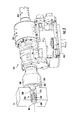
- FIG. 7 schematically illustrates a longitudinal cross-sectional view of a countersinking device, according to one aspect of the present disclosure.
- FIG. 8 schematically illustrates a method of forming a portable countersinking device, according to one aspect of the present disclosure.
- a portable countersinking device 100 comprising an internal bore positioner 200 adapted to be received by a bore 50 defined by a workpiece 75 .
- a driver rod 300 is engaged with the internal bore positioner 200 and is configured to extend outwardly of the bore 50 through a bore opening 60 in a surface 70 of the workpiece 75 .
- a centering chuck 400 is engaged about the driver rod 300 .
- the centering chuck 400 is configure to be movable longitudinally or axially along the driver rod 300 , and to engage the bore opening 60 so as to cooperate with the internal bore positioner 200 to align the driver rod 300 along a longitudinal axis 80 of the bore 50 .
- a counterbore 500 is engaged about the driver rod 300 , generally opposite to the centering chuck 400 from the internal bore positioner 200 .
- the counterbore 500 is configured to be rotatable about the driver rod 300 and to be axially advanced along the driver rod 300 to engage the bore opening 60 and to countersink the bore 50 .
- a countersink depth control arrangement is associated with the counterbore 500 and is configured to cooperate therewith to countersink the bore 50 to a predetermined depth.
- the internal bore positioner 200 comprises a collet 210 configured to be actuatable between a radially-contracted arrangement (see, e.g., FIGS. 1-3 and 6 ), for allowing the collet 210 to be inserted into and removed from the bore 50 , and a radially-expanded arrangement (see, e.g., FIGS. 4 and 5 ), for securing the collet 210 at a selected depth within the bore 50 .
- the collet 210 is pneumatically actuatable between the radially-contracted arrangement and the radially-expanded arrangement via the driver rod 300 .
- the collet 210 may have a generally (hollow) cylindrical configuration, including a plurality of longitudinally-extending and angularly-arranged gripping members 220 collectively defining the hollow cylinder.
- the driver rod 300 may be configured to have a mandrel 600 coaxially engaged therewith.
- the mandrel 600 may be received by and within the driver rod 300 and configured to be axially movable with respect thereto.
- the mandrel 600 may be axially movable with respect to the driver rod 300 , between an axially-contracted position (see, e.g., FIGS. 4 and 5 ) and an axially-extended position (see, e.g., FIGS.
- the mandrel 600 may be axially movable, for instance, in response to a pneumatic actuator 650 (i.e., an air cylinder/solenoid) engaged with the driver rod 300 , with the air pressure imparted thereby being operable on the mandrel 600 through the driver rod 300 .
- a pneumatic actuator 650 i.e., an air cylinder/solenoid
- the mandrel 600 may be received by the collet 210 (i.e., within the gripping members 220 defining the hollow cylinder) such that, in the axially-extended position of the mandrel 600 with respect to the driver rod 300 , the collet 210 is in the radially-contracted arrangement and, in the axially-contracted position of the mandrel 600 with respect to the driver rod 300 , the collet 210 is in the radially-expanded arrangement.
- the countersinking device 100 may further comprise a shroud 700 (i.e., a nosepiece) extending about the driver rod 300 and the counterbore 500 .
- a vacuum source 800 may be operably engaged with the shroud 700 via a vacuum port 750 defined by the shroud 700 , wherein the vacuum source 800 is configured to cooperate with the vacuum port 750 to evacuate portions of the workpiece 75 removed by the counterbore 500 from the shroud 700 . That is, a suction or vacuum provided by the vacuum source 800 is directed to interact with the shroud 700 via the vacuum port 750 to remove shavings, chips, etc. of the workpiece 75 removed by the counterbore 500 countersinking the bore 50 .
- the shroud 700 may be axially fixed with respect to the driver rod 300 .
- the collet 210 may be configured to cooperate with the mandrel 600 and the driver rod 300 such that the collet 210 in the radially-contracted arrangement (i.e., with the mandrel 600 in the axially-extended position with respect to the driver rod 300 ) is insertable into the bore 50 defined by the workpiece.
- the collet 210 may be inserted into the bore 50 until the shroud 700 engages the surface 70 of the workpiece 75 .
- the centering chuck 400 disposed between the internal bore positioner 200 and the counterbore 500 , and when engaged with the counterbore 500 disposed within the shroud 700 , may extend axially toward the internal bore positioner 200 to a greater extent than the shroud 700 . That is, the centering chuck 400 , when normally engaged with the counterbore 500 , extends outwardly of the shroud 700 toward the collet 210 . In some instances, the centering chuck 400 is engaged with and serially disposed with respect to the counterbore 500 , and is rotatable therewith about the driver rod 300 , to thereby be configured as a countersink pilot.
- the centering chuck 400 proceeds the shroud 700 to engage the bore 50 (see, e.g., FIGS. 3 and 4 ).
- the first and centering chucks 200 , 400 may thus cooperate to align the driver rod 300 along a longitudinal axis 80 of the bore 50 .
- the collet 210 upon actuation of the pneumatic actuator 650 , the collet 210 , which is inserted into the bore 50 such that the shroud 700 engages the surface 70 of the workpiece 75 , and such that the centering chuck 400 (i.e., countersink pilot) engages the bore 50 , radially expands to the radially-expanded arrangement in response to the mandrel 600 being moved toward the axially-contracted position.
- the collet 210 being expanded into the radially-expanded arrangement thus causes the angularly-arranged gripping members 220 collectively defining the hollow cylinder to expand radially outward to engage or grip the wall of the bore 50 .
- the second positioning member 400 may be sized to the dimension (i.e., diameter) of the bore 50 , or may be a tapered or radially expanding member. Accordingly, both the first and centering chucks 200 , 400 are configured to align the driver rod 300 along a longitudinal axis 80 of the bore 50 , prior to the initiation of the countersink process via the countersink member 500 .
- the throw (i.e., the range of axial movement) of the mandrel 600 with respect to the driver rod 300 may further draw or advance the shroud 700 toward the collet 210 (i.e., in response to axial movement of the mandrel 300 to the axially-contracted position to actuate the collet 210 to the radially-expanded position) such that the shroud 700 is securely engaged with and held against the surface 70 of the workpiece 75 .
- the shroud 700 may serve to support the surface 70 of the workpiece 75 about the bore 50 so as to lessen the risk of deformation of the surface 70 about the bore during the countersinking process.
- the secure arrangement with the workpiece 75 may thus provide improved positioning and guiding of the counterbore 500 to countersink the bore 50 .
- a drive element 825 may further be operably engaged with the counterbore 500 , wherein the drive element 825 is configured to rotate the counterbore 500 (i.e., using a servo-driven spindle for accurate control of spindle rotational speed, with stall warning and load monitoring capabilities) about the driver rod 300 (i.e., the elongate remember 300 remains stationary and does not rotate about the longitudinal axis 80 ) and to axially advance the counterbore 500 (i.e., using a servo axial feed device for precise feed rate and axial position control) along the driver rod 300 (at least partially guided by the centering chuck 400 ), such that the counterbore 500 engages and countersinks the bore 50 about the surface 70 of the workpiece 75 to a preselected depth.
- the drive element 825 is configured to rotate the counterbore 500 (i.e., using a servo-driven spindle for accurate control of spindle rotational speed, with stall warning and load monitoring capabilities) about the driver rod 300 (
- a drive element controller 900 may be arranged in communication with the drive element 825 .
- the drive element 825 may be further configured to rotate and axially advance the counterbore 500 with respect to the workpiece 75 , in response to rotational speed and feed rate parameters, for example, associated with the workpiece 75 , wherein such parameters are communicated to the drive element 825 by the drive element controller 900 . That is, for a particular workpiece 75 comprised of a particular material, the drive element controller 900 may be programmed to rotate the counterbore 500 at a certain rotational speed (i.e., rpm) and to advance the counterbore 500 into the workpiece 75 at a certain rate (i.e., feed rate).
- rotational speed and feed rate may vary depending on many different factors and thus are not necessarily required to be constant, but could alternately be variable (i.e., the rotational speed or feed rate could vary depending on the depth of the counterbore 500 within the workpiece 75 ).
- the depth of the countersink in the workpiece 75 may be determined in different manners.
- the countersink depth control arrangement may comprise a sensor 850 (see, e.g., FIG. 7 ) configured to determine that the centering chuck 400 has advanced into the bore 50 , in association with the counterbore 500 , to engage the internal bore positioner 200 .
- the engagement between the first and centering chucks 200 , 400 may be sensed by the sensor 850 as, for example, an increased axial load or a decreased rotational load on the drive element 825 .
- the sensor 850 may be configured to determine the axial extent to which the counterbore 500 has been advanced (without necessarily determining any engagement between the first and centering chucks 200 , 400 ).
- the sensor 850 may be configured to direct the drive element 825 to axially retract the counterbore 500 along the driver rod 300 , for example, to within the shroud 700 .
- the collet 210 can be returned to the radially-contracted arrangement by actuating the mandrel 600 to the axially-extended position with respect to the driver rod 300 , wherein the entire countersinking device can then be removed from the countersunk bore 50 (see, e.g., FIG. 6 ).
- FIG. 8 schematically illustrates a method of forming a portable countersinking device.
- Such a method may comprise engaging a driver rod with an internal bore positioner, adapted to be received by a bore defined by a workpiece, wherein the driver rod is configured to extend from the internal bore positioner and outwardly of the bore through a bore opening in a surface of the workpiece (Block 950 ).
- a centering chuck is engaged about the driver rod, wherein the centering chuck is axially movable along the driver rod and is configured to engage the bore opening so as to cooperate with the internal bore positioner to align the driver rod along a longitudinal axis of the bore (Block 960 ).
- a counterbore is engaged about the driver rod, opposite the centering chuck from the internal bore positioner, wherein the counterbore is rotatable about the driver rod and is configured to be axially advanced along the driver rod to engage the bore opening and to countersink the bore (Block 970 ).
- a countersink depth control arrangement is associated with the counterbore, the countersink depth control element being configured to cooperate with the counterbore to countersink the bore to a predetermined depth (Block 980 ).
- aspects of the present disclosure thus provide a portable countersinking device and associated method which may allow the realization of improved ergonomics for an operator in a countersinking process requiring portable and automated tools. Such aspects also remove the need for manual feeding or rotation of the counterbore by the operator.
- the portability of the disclosed device combined with the automation of the process, allows increased and improved control of the countersinking process which, in turn, provides improved process quality and consistency at increased cycle speeds. Accordingly, less rework is required.
Landscapes
- Engineering & Computer Science (AREA)
- Mechanical Engineering (AREA)
- Drilling And Boring (AREA)
- Gripping On Spindles (AREA)
Priority Applications (5)
| Application Number | Priority Date | Filing Date | Title |
|---|---|---|---|
| US15/010,577 US10173270B2 (en) | 2016-01-29 | 2016-01-29 | Countersinking device and associated method |
| EP16197512.3A EP3199280B1 (fr) | 2016-01-29 | 2016-11-07 | Dispositif de fraisage et procédé associé |
| KR1020160159466A KR20170090990A (ko) | 2016-01-29 | 2016-11-28 | 카운터싱크 장치 및 이와 관련된 방법 |
| JP2017002256A JP6876440B2 (ja) | 2016-01-29 | 2017-01-11 | カウンタシンク加工用装置及びカウンタシンク加工用装置に関連する方法 |
| CN201710049307.4A CN107020404B (zh) | 2016-01-29 | 2017-01-23 | 钻埋头孔装置和相关方法 |
Applications Claiming Priority (1)
| Application Number | Priority Date | Filing Date | Title |
|---|---|---|---|
| US15/010,577 US10173270B2 (en) | 2016-01-29 | 2016-01-29 | Countersinking device and associated method |
Publications (2)
| Publication Number | Publication Date |
|---|---|
| US20170216934A1 US20170216934A1 (en) | 2017-08-03 |
| US10173270B2 true US10173270B2 (en) | 2019-01-08 |
Family
ID=57241004
Family Applications (1)
| Application Number | Title | Priority Date | Filing Date |
|---|---|---|---|
| US15/010,577 Expired - Fee Related US10173270B2 (en) | 2016-01-29 | 2016-01-29 | Countersinking device and associated method |
Country Status (5)
| Country | Link |
|---|---|
| US (1) | US10173270B2 (fr) |
| EP (1) | EP3199280B1 (fr) |
| JP (1) | JP6876440B2 (fr) |
| KR (1) | KR20170090990A (fr) |
| CN (1) | CN107020404B (fr) |
Families Citing this family (1)
| Publication number | Priority date | Publication date | Assignee | Title |
|---|---|---|---|---|
| CN110497532B (zh) * | 2019-09-02 | 2021-01-12 | 杨家益 | 一种便于操作的锚栓预安装工具及其使用方法 |
Citations (22)
| Publication number | Priority date | Publication date | Assignee | Title |
|---|---|---|---|---|
| US2665597A (en) | 1951-03-08 | 1954-01-12 | Boeing Co | Expansible anchor |
| US2669887A (en) | 1950-08-17 | 1954-02-23 | Reed Roller Bit Co | Countersinking apparatus |
| US2706917A (en) | 1950-12-04 | 1955-04-26 | Boeing Co | Portable countersinking tool |
| US4688970A (en) * | 1985-08-09 | 1987-08-25 | Dresser Industries, Inc. | Power drill and automatic control system therefore |
| US5775853A (en) | 1996-09-03 | 1998-07-07 | Makino Inc. | Machining method and multi-function tool |
| US5997222A (en) | 1998-10-30 | 1999-12-07 | The Boeing Company | Externally indexing countersink pilot guide |
| US6012877A (en) * | 1996-12-13 | 2000-01-11 | The Boeing Company | Self-centering end effector |
| US6036409A (en) * | 1997-01-23 | 2000-03-14 | The Boeing Company | Blind hole self-collet countersink |
| US7755761B2 (en) | 2004-11-12 | 2010-07-13 | The Boeing Company | Self-normalizing contour drilling machine |
| US8006362B2 (en) | 2007-04-06 | 2011-08-30 | The Boeing Company | Method and apparatus for installing fasteners |
| US8096038B2 (en) | 2007-05-11 | 2012-01-17 | The Boeing Company | Robotic end effector and clamping method |
| US8167518B2 (en) | 2008-04-11 | 2012-05-01 | The Boeing Company | Method and apparatus for a spindle with servo feed control |
| US8171642B2 (en) | 2005-08-05 | 2012-05-08 | The Boeing Company | Method for forming a flexible single rail drilling system |
| US8454281B2 (en) | 2008-08-28 | 2013-06-04 | The Boeing Company | Chamfer tool |
| US8454280B2 (en) | 2003-10-20 | 2013-06-04 | The Boeing Company | Formation of a pattern of holes in a structure |
| US8464434B1 (en) | 2010-09-15 | 2013-06-18 | The Boeing Company | Hole and countersink measurement system |
| US8668410B1 (en) | 2009-11-13 | 2014-03-11 | The Boeing Company | Drilling system stabilization |
| US8696267B2 (en) | 2010-12-20 | 2014-04-15 | Sudershan K Khurana | Drill/countersink assembly and method for producing countersunk holes |
| US9162332B2 (en) | 2013-01-31 | 2015-10-20 | The Boeing Company | Method and apparatus for automated multi-drilling and multi-rivet machine |
| US9199715B2 (en) | 2013-10-10 | 2015-12-01 | The Boeing Company | Self-aligning fitting assemblies and systems and methods including the same |
| US9205933B2 (en) | 2011-12-15 | 2015-12-08 | The Boeing Company | Automated assembly of panelized aircraft fuselages |
| US9259779B2 (en) | 2012-01-04 | 2016-02-16 | The Boeing Company | Riveting tool and method with electromagnetic bucking bar normalization |
Family Cites Families (15)
| Publication number | Priority date | Publication date | Assignee | Title |
|---|---|---|---|---|
| US4286902A (en) * | 1980-01-09 | 1981-09-01 | Dresser Industries, Inc. | Self-colleting drill |
| JPH0767644B2 (ja) * | 1988-02-18 | 1995-07-26 | 株式会社東芝 | 可搬式中ぐり装置 |
| CN1304154C (zh) * | 2003-02-26 | 2007-03-14 | 李宝田 | 划窝复合埋头钻 |
| TR201911015T4 (tr) * | 2003-06-25 | 2019-08-21 | Boeing Co | Üretim operasyonları için aparat ve yöntemler. |
| EP2289655B1 (fr) * | 2009-08-26 | 2019-06-19 | General Electric Company | Appareil et outils à utiliser avec des compresseurs |
| CN101690981A (zh) * | 2009-09-28 | 2010-04-07 | 中国民航大学 | 具有负压钻屑动态收集功能的钻削气动工具 |
| US8651776B2 (en) * | 2010-08-30 | 2014-02-18 | Sudershan Khurana | Drill/countersink assembly and method for producing countersunk holes |
| CN202317142U (zh) * | 2011-08-16 | 2012-07-11 | 安阳鑫盛机床股份有限公司 | 一种对沉孔深度有精度要求的埋头钻限位机构 |
| CN202291549U (zh) * | 2011-10-28 | 2012-07-04 | 上海汇众汽车制造有限公司 | 双向去毛刺倒角组合刀具 |
| JP5714556B2 (ja) * | 2012-12-05 | 2015-05-07 | 株式会社スギノマシン | 穿孔装置のクランプ装置及びエア駆動ドリル装置 |
| CN104802138B (zh) * | 2014-01-27 | 2017-01-11 | 苏州宝时得电动工具有限公司 | 动力工具 |
| CN104416201A (zh) * | 2013-08-31 | 2015-03-18 | 朱振明 | 一种汽车模具圆孔倒角钻头 |
| CN203992505U (zh) * | 2014-08-18 | 2014-12-10 | 攀枝花学院 | 一种钻孔机 |
| CN204504275U (zh) * | 2015-03-17 | 2015-07-29 | 浙江来福谐波传动股份有限公司 | 一种自定心内胀芯轴夹具 |
| CN204934684U (zh) * | 2015-07-27 | 2016-01-06 | 安徽海立精密铸造有限公司 | 导向倒角钻 |
-
2016
- 2016-01-29 US US15/010,577 patent/US10173270B2/en not_active Expired - Fee Related
- 2016-11-07 EP EP16197512.3A patent/EP3199280B1/fr active Active
- 2016-11-28 KR KR1020160159466A patent/KR20170090990A/ko not_active Application Discontinuation
-
2017
- 2017-01-11 JP JP2017002256A patent/JP6876440B2/ja active Active
- 2017-01-23 CN CN201710049307.4A patent/CN107020404B/zh not_active Expired - Fee Related
Patent Citations (24)
| Publication number | Priority date | Publication date | Assignee | Title |
|---|---|---|---|---|
| US2669887A (en) | 1950-08-17 | 1954-02-23 | Reed Roller Bit Co | Countersinking apparatus |
| US2706917A (en) | 1950-12-04 | 1955-04-26 | Boeing Co | Portable countersinking tool |
| US2665597A (en) | 1951-03-08 | 1954-01-12 | Boeing Co | Expansible anchor |
| US4688970A (en) * | 1985-08-09 | 1987-08-25 | Dresser Industries, Inc. | Power drill and automatic control system therefore |
| US5775853A (en) | 1996-09-03 | 1998-07-07 | Makino Inc. | Machining method and multi-function tool |
| US6012877A (en) * | 1996-12-13 | 2000-01-11 | The Boeing Company | Self-centering end effector |
| US6036409A (en) * | 1997-01-23 | 2000-03-14 | The Boeing Company | Blind hole self-collet countersink |
| US5997222A (en) | 1998-10-30 | 1999-12-07 | The Boeing Company | Externally indexing countersink pilot guide |
| US8454280B2 (en) | 2003-10-20 | 2013-06-04 | The Boeing Company | Formation of a pattern of holes in a structure |
| US7755761B2 (en) | 2004-11-12 | 2010-07-13 | The Boeing Company | Self-normalizing contour drilling machine |
| US8171642B2 (en) | 2005-08-05 | 2012-05-08 | The Boeing Company | Method for forming a flexible single rail drilling system |
| US8006362B2 (en) | 2007-04-06 | 2011-08-30 | The Boeing Company | Method and apparatus for installing fasteners |
| US8479382B2 (en) | 2007-04-06 | 2013-07-09 | The Boeing Company | Apparatus for installing fasteners |
| US8096038B2 (en) | 2007-05-11 | 2012-01-17 | The Boeing Company | Robotic end effector and clamping method |
| US8925184B2 (en) | 2007-05-11 | 2015-01-06 | The Boeing Company | Robotic end effector and clamping method |
| US8167518B2 (en) | 2008-04-11 | 2012-05-01 | The Boeing Company | Method and apparatus for a spindle with servo feed control |
| US8454281B2 (en) | 2008-08-28 | 2013-06-04 | The Boeing Company | Chamfer tool |
| US8668410B1 (en) | 2009-11-13 | 2014-03-11 | The Boeing Company | Drilling system stabilization |
| US8464434B1 (en) | 2010-09-15 | 2013-06-18 | The Boeing Company | Hole and countersink measurement system |
| US8696267B2 (en) | 2010-12-20 | 2014-04-15 | Sudershan K Khurana | Drill/countersink assembly and method for producing countersunk holes |
| US9205933B2 (en) | 2011-12-15 | 2015-12-08 | The Boeing Company | Automated assembly of panelized aircraft fuselages |
| US9259779B2 (en) | 2012-01-04 | 2016-02-16 | The Boeing Company | Riveting tool and method with electromagnetic bucking bar normalization |
| US9162332B2 (en) | 2013-01-31 | 2015-10-20 | The Boeing Company | Method and apparatus for automated multi-drilling and multi-rivet machine |
| US9199715B2 (en) | 2013-10-10 | 2015-12-01 | The Boeing Company | Self-aligning fitting assemblies and systems and methods including the same |
Non-Patent Citations (1)
| Title |
|---|
| European Search Report dated May 29, 2017 for Application No. 16197512.3. |
Also Published As
| Publication number | Publication date |
|---|---|
| US20170216934A1 (en) | 2017-08-03 |
| EP3199280A1 (fr) | 2017-08-02 |
| EP3199280B1 (fr) | 2020-05-20 |
| CN107020404A (zh) | 2017-08-08 |
| KR20170090990A (ko) | 2017-08-08 |
| JP6876440B2 (ja) | 2021-05-26 |
| JP2017164889A (ja) | 2017-09-21 |
| CN107020404B (zh) | 2020-08-11 |
Similar Documents
| Publication | Publication Date | Title |
|---|---|---|
| US8210778B2 (en) | Method and device for clamping and machining | |
| US3060772A (en) | Countersink tool and control means | |
| EP2164663B1 (fr) | Procédé de commande d'une machine à percer, et appareil pour la mise en oeuvre d'un tel procédé | |
| JP2016522754A (ja) | 材料除去工作機械、ツールセットおよび盲目穴及び/又は段付き穴を有するシリンダの製造方法 | |
| CN103862292A (zh) | 金属切削用组合机床 | |
| CN103862312A (zh) | 一种卧式机床自动夹紧装置以及卧式机床 | |
| US10173270B2 (en) | Countersinking device and associated method | |
| JPWO2018105009A1 (ja) | 加工装置、加工装置の使用方法及びチャック装置 | |
| KR101807827B1 (ko) | 심압대 개조 선반의 파이프위치조절장치 및 파이프위치 조절장치를 이용한 파이프 가공방법 | |
| US10583498B1 (en) | Apparatus for retaining a workpiece | |
| CN104625733B (zh) | 旋转式孔型零件加工装置 | |
| JP6600194B2 (ja) | チャック装置 | |
| CN104227418A (zh) | 法兰轴专用加工设备 | |
| CN215509036U (zh) | 用于车床同心加工的弹性涨夹装置 | |
| CN203380391U (zh) | 一种自动钻孔机 | |
| KR101305422B1 (ko) | Cnc 선반용 스핀들 유니트 및 스핀들 유니트를 이용한 밸브용 금속패킹 가공방법 | |
| CN102861804B (zh) | 铝圆管加强筋滚压工艺及装置 | |
| CN212019425U (zh) | 一种保持架加工用夹具 | |
| JP2017164889A5 (fr) | ||
| JP4605936B2 (ja) | 同一円周上の複数箇所の旋削加工方法 | |
| CN211029122U (zh) | 轴套车削加工时的夹紧机构 | |
| US20240286204A1 (en) | Collet chuck | |
| CN218396317U (zh) | 一种车床用快速攻丝/攻扣辅助装置 | |
| CN108637759B (zh) | 一种数控车床用的旋转式夹具 | |
| CN219582185U (zh) | 一种新型的自动抓取附件头装置 |
Legal Events
| Date | Code | Title | Description |
|---|---|---|---|
| AS | Assignment |
Owner name: THE BOEING COMPANY, CALIFORNIA Free format text: ASSIGNMENT OF ASSIGNORS INTEREST;ASSIGNOR:MICKELSON, DEREK;REEL/FRAME:037621/0941 Effective date: 20160121 |
|
| STCF | Information on status: patent grant |
Free format text: PATENTED CASE |
|
| FEPP | Fee payment procedure |
Free format text: MAINTENANCE FEE REMINDER MAILED (ORIGINAL EVENT CODE: REM.); ENTITY STATUS OF PATENT OWNER: LARGE ENTITY |
|
| LAPS | Lapse for failure to pay maintenance fees |
Free format text: PATENT EXPIRED FOR FAILURE TO PAY MAINTENANCE FEES (ORIGINAL EVENT CODE: EXP.); ENTITY STATUS OF PATENT OWNER: LARGE ENTITY |
|
| STCH | Information on status: patent discontinuation |
Free format text: PATENT EXPIRED DUE TO NONPAYMENT OF MAINTENANCE FEES UNDER 37 CFR 1.362 |
|
| FP | Lapsed due to failure to pay maintenance fee |
Effective date: 20230108 |