US10117835B2 - Nozzle, apparatus, and method for producing microparticles - Google Patents
Nozzle, apparatus, and method for producing microparticles Download PDFInfo
- Publication number
- US10117835B2 US10117835B2 US15/378,292 US201615378292A US10117835B2 US 10117835 B2 US10117835 B2 US 10117835B2 US 201615378292 A US201615378292 A US 201615378292A US 10117835 B2 US10117835 B2 US 10117835B2
- Authority
- US
- United States
- Prior art keywords
- fluid
- phase fluid
- oil phase
- microparticles
- extension tubes
- Prior art date
- Legal status (The legal status is an assumption and is not a legal conclusion. Google has not performed a legal analysis and makes no representation as to the accuracy of the status listed.)
- Active, expires
Links
Images


Classifications
-
- A—HUMAN NECESSITIES
- A61—MEDICAL OR VETERINARY SCIENCE; HYGIENE
- A61K—PREPARATIONS FOR MEDICAL, DENTAL OR TOILETRY PURPOSES
- A61K9/00—Medicinal preparations characterised by special physical form
- A61K9/14—Particulate form, e.g. powders, Processes for size reducing of pure drugs or the resulting products, Pure drug nanoparticles
- A61K9/16—Agglomerates; Granulates; Microbeadlets ; Microspheres; Pellets; Solid products obtained by spray drying, spray freeze drying, spray congealing,(multiple) emulsion solvent evaporation or extraction
- A61K9/1682—Processes
-
- B—PERFORMING OPERATIONS; TRANSPORTING
- B01—PHYSICAL OR CHEMICAL PROCESSES OR APPARATUS IN GENERAL
- B01J—CHEMICAL OR PHYSICAL PROCESSES, e.g. CATALYSIS OR COLLOID CHEMISTRY; THEIR RELEVANT APPARATUS
- B01J13/00—Colloid chemistry, e.g. the production of colloidal materials or their solutions, not otherwise provided for; Making microcapsules or microballoons
- B01J13/02—Making microcapsules or microballoons
- B01J13/06—Making microcapsules or microballoons by phase separation
- B01J13/08—Simple coacervation, i.e. addition of highly hydrophilic material
-
- B—PERFORMING OPERATIONS; TRANSPORTING
- B01—PHYSICAL OR CHEMICAL PROCESSES OR APPARATUS IN GENERAL
- B01J—CHEMICAL OR PHYSICAL PROCESSES, e.g. CATALYSIS OR COLLOID CHEMISTRY; THEIR RELEVANT APPARATUS
- B01J13/00—Colloid chemistry, e.g. the production of colloidal materials or their solutions, not otherwise provided for; Making microcapsules or microballoons
- B01J13/02—Making microcapsules or microballoons
- B01J13/06—Making microcapsules or microballoons by phase separation
- B01J13/12—Making microcapsules or microballoons by phase separation removing solvent from the wall-forming material solution
-
- B—PERFORMING OPERATIONS; TRANSPORTING
- B01—PHYSICAL OR CHEMICAL PROCESSES OR APPARATUS IN GENERAL
- B01J—CHEMICAL OR PHYSICAL PROCESSES, e.g. CATALYSIS OR COLLOID CHEMISTRY; THEIR RELEVANT APPARATUS
- B01J13/00—Colloid chemistry, e.g. the production of colloidal materials or their solutions, not otherwise provided for; Making microcapsules or microballoons
- B01J13/02—Making microcapsules or microballoons
- B01J13/20—After-treatment of capsule walls, e.g. hardening
-
- B—PERFORMING OPERATIONS; TRANSPORTING
- B01—PHYSICAL OR CHEMICAL PROCESSES OR APPARATUS IN GENERAL
- B01J—CHEMICAL OR PHYSICAL PROCESSES, e.g. CATALYSIS OR COLLOID CHEMISTRY; THEIR RELEVANT APPARATUS
- B01J2/00—Processes or devices for granulating materials, e.g. fertilisers in general; Rendering particulate materials free flowing in general, e.g. making them hydrophobic
- B01J2/02—Processes or devices for granulating materials, e.g. fertilisers in general; Rendering particulate materials free flowing in general, e.g. making them hydrophobic by dividing the liquid material into drops, e.g. by spraying, and solidifying the drops
- B01J2/06—Processes or devices for granulating materials, e.g. fertilisers in general; Rendering particulate materials free flowing in general, e.g. making them hydrophobic by dividing the liquid material into drops, e.g. by spraying, and solidifying the drops in a liquid medium
-
- B—PERFORMING OPERATIONS; TRANSPORTING
- B01—PHYSICAL OR CHEMICAL PROCESSES OR APPARATUS IN GENERAL
- B01J—CHEMICAL OR PHYSICAL PROCESSES, e.g. CATALYSIS OR COLLOID CHEMISTRY; THEIR RELEVANT APPARATUS
- B01J2/00—Processes or devices for granulating materials, e.g. fertilisers in general; Rendering particulate materials free flowing in general, e.g. making them hydrophobic
- B01J2/18—Processes or devices for granulating materials, e.g. fertilisers in general; Rendering particulate materials free flowing in general, e.g. making them hydrophobic using a vibrating apparatus
-
- B—PERFORMING OPERATIONS; TRANSPORTING
- B29—WORKING OF PLASTICS; WORKING OF SUBSTANCES IN A PLASTIC STATE IN GENERAL
- B29B—PREPARATION OR PRETREATMENT OF THE MATERIAL TO BE SHAPED; MAKING GRANULES OR PREFORMS; RECOVERY OF PLASTICS OR OTHER CONSTITUENTS OF WASTE MATERIAL CONTAINING PLASTICS
- B29B9/00—Making granules
- B29B9/10—Making granules by moulding the material, i.e. treating it in the molten state
-
- B—PERFORMING OPERATIONS; TRANSPORTING
- B29—WORKING OF PLASTICS; WORKING OF SUBSTANCES IN A PLASTIC STATE IN GENERAL
- B29B—PREPARATION OR PRETREATMENT OF THE MATERIAL TO BE SHAPED; MAKING GRANULES OR PREFORMS; RECOVERY OF PLASTICS OR OTHER CONSTITUENTS OF WASTE MATERIAL CONTAINING PLASTICS
- B29B9/00—Making granules
- B29B9/12—Making granules characterised by structure or composition
-
- B—PERFORMING OPERATIONS; TRANSPORTING
- B29—WORKING OF PLASTICS; WORKING OF SUBSTANCES IN A PLASTIC STATE IN GENERAL
- B29B—PREPARATION OR PRETREATMENT OF THE MATERIAL TO BE SHAPED; MAKING GRANULES OR PREFORMS; RECOVERY OF PLASTICS OR OTHER CONSTITUENTS OF WASTE MATERIAL CONTAINING PLASTICS
- B29B9/00—Making granules
- B29B9/16—Auxiliary treatment of granules
-
- A—HUMAN NECESSITIES
- A61—MEDICAL OR VETERINARY SCIENCE; HYGIENE
- A61K—PREPARATIONS FOR MEDICAL, DENTAL OR TOILETRY PURPOSES
- A61K9/00—Medicinal preparations characterised by special physical form
- A61K9/14—Particulate form, e.g. powders, Processes for size reducing of pure drugs or the resulting products, Pure drug nanoparticles
- A61K9/16—Agglomerates; Granulates; Microbeadlets ; Microspheres; Pellets; Solid products obtained by spray drying, spray freeze drying, spray congealing,(multiple) emulsion solvent evaporation or extraction
- A61K9/1605—Excipients; Inactive ingredients
- A61K9/1629—Organic macromolecular compounds
- A61K9/1641—Organic macromolecular compounds obtained otherwise than by reactions only involving carbon-to-carbon unsaturated bonds, e.g. polyethylene glycol, poloxamers
- A61K9/1647—Polyesters, e.g. poly(lactide-co-glycolide)
-
- B—PERFORMING OPERATIONS; TRANSPORTING
- B29—WORKING OF PLASTICS; WORKING OF SUBSTANCES IN A PLASTIC STATE IN GENERAL
- B29B—PREPARATION OR PRETREATMENT OF THE MATERIAL TO BE SHAPED; MAKING GRANULES OR PREFORMS; RECOVERY OF PLASTICS OR OTHER CONSTITUENTS OF WASTE MATERIAL CONTAINING PLASTICS
- B29B9/00—Making granules
- B29B9/16—Auxiliary treatment of granules
- B29B2009/168—Removing undesirable residual components, e.g. solvents, unreacted monomers; Degassing
-
- B—PERFORMING OPERATIONS; TRANSPORTING
- B29—WORKING OF PLASTICS; WORKING OF SUBSTANCES IN A PLASTIC STATE IN GENERAL
- B29K—INDEXING SCHEME ASSOCIATED WITH SUBCLASSES B29B, B29C OR B29D, RELATING TO MOULDING MATERIALS OR TO MATERIALS FOR MOULDS, REINFORCEMENTS, FILLERS OR PREFORMED PARTS, e.g. INSERTS
- B29K2105/00—Condition, form or state of moulded material or of the material to be shaped
- B29K2105/0005—Condition, form or state of moulded material or of the material to be shaped containing compounding ingredients
- B29K2105/0035—Medical or pharmaceutical agents
-
- B—PERFORMING OPERATIONS; TRANSPORTING
- B29—WORKING OF PLASTICS; WORKING OF SUBSTANCES IN A PLASTIC STATE IN GENERAL
- B29K—INDEXING SCHEME ASSOCIATED WITH SUBCLASSES B29B, B29C OR B29D, RELATING TO MOULDING MATERIALS OR TO MATERIALS FOR MOULDS, REINFORCEMENTS, FILLERS OR PREFORMED PARTS, e.g. INSERTS
- B29K2995/00—Properties of moulding materials, reinforcements, fillers, preformed parts or moulds
- B29K2995/0037—Other properties
- B29K2995/0059—Degradable
- B29K2995/006—Bio-degradable, e.g. bioabsorbable, bioresorbable or bioerodible
Definitions
- the present disclosure relates to a nozzle, an apparatus, and a method for producing microparticles and, more particularly, to a nozzle, an apparatus, and a method for mass production of microparticles.
- Microparticles also known as microspheres, are spherical particles having a diameter smaller than 1000 ⁇ m, are generally used as microcarriers for releasing drug, and have become one of the emerging drug delivery technologies due to the characteristics of targeting, controlled release, stability, and surface modifiability.
- a conventional nozzle 9 shown in FIG. 1 can be used for mass production of microparticles.
- the conventional nozzle 9 for producing microparticles includes a fluid passageway 91 and a plurality of openings 92 intercommunicated with the fluid passageway 91 .
- An oil phase solution can be filled into the fluid passageway 91 .
- the oil phase solution flows out of the nozzle 9 via the openings 92 and forms a droplet on each opening 92 by surface tension.
- the droplet exits the corresponding opening 92 and falls into a water phase solution which envelops the droplet formed by the oil phase solution, assisting in curing and shaping of the droplet. Mass production of microparticles is, thus, achieved.
- the above conventional nozzle 9 can proceed with mass production of microparticles, the surface extensions or pressures in the openings 92 could be different, leading to diverse microparticle diameters. Thus, the microparticles have poor uniformity and, thus, have different drug releasing effects.
- the diameters of the microparticles are influenced by the concentration of the oil phase solution, leading to difficulties in control of the diameters of the microparticles while using the conventional nozzle 9 to produce microparticles.
- the concentration of the oil phase solution filled into the fluid passageway 91 is too high (e.g., the concentration of the polymer material is larger than 9 wt %), each droplet must be accumulated to be heavier for exiting the corresponding opening 92 , resulting in an oversize microparticle that might not fulfill the production demand of microparticles.
- the conventional nozzle 9 cannot be used to produce microparticles from a high-concentration oil phase solution. Accordingly, it is difficult to control the diameters of the microparticles produced by the conventional nozzle 9 , and the conventional nozzle 9 has fewer applications.
- the oil phase solution it takes a long period of time for the oil phase solution to accumulate on each opening 92 to form a droplet until the weight of the droplet is sufficient to exit the opening 92 , such that the productivity of microparticles produced by the conventional nozzle 9 is low.
- the water phase solution is a static fluid, the droplets falling into the water phase solution are apt to aggregate, such that the respective droplet cannot be enveloped and shaped by the water phase solution, resulting in a low yield of microparticles produced by the conventional nozzle 9 .
- the present disclosure provides a nozzle, an apparatus, and a method for producing microparticles of a uniform size.
- a nozzle for producing microparticles includes a nozzle body having a fluid passageway therein.
- a plurality of extension tubes is communicated with an end of the fluid passageway.
- Each of the plurality of extension tubes includes a distant end having an outlet port and located distant to the fluid passageway.
- the outlet ports of the plurality of extension tubes are spaced from each other.
- the plurality of extension tubes is parallel to each other, such that an oil phase fluid can flow out of the nozzle body in the same direction.
- the outlet port of each of the plurality of extension tubes has a diameter
- each of the plurality of extension tubes includes a tubular wall having a thickness smaller than the diameter.
- the outlet port of each of the plurality of extension tubes has a diameter.
- Two adjacent extension tubes have a minimum spacing therebetween. The minimum spacing is larger than the diameter to avoid mixing of the continuous oil phase fluids flowing out of adjacent extension tubes.
- each of the plurality of extension tubes having the outlet port is an inclined end.
- the contact area between the oil phase fluid and each of the plurality of extension tubes can be further reduced to reliably avoid the oil phase fluid from accumulating in each outlet port, thereby more effectively reducing the adverse influence on the diameters of the microparticle products by the surface tension.
- each of the plurality of extension tubes having the outlet port includes a layer of hydrophobic material.
- the oil phase fluid flowing out of each outlet port comes in contact with the layer of hydrophobic material, the oil phase fluid is less likely to adhere to each of the plurality of extension tubes to reliably prevent the oil phase fluid from accumulating in each outlet port, thereby more effectively reducing the influence on the diameters of the microparticle products by the surface tension.
- An apparatus for producing microparticles according to the present disclosure includes the above-mentioned nozzle.
- the apparatus further includes a fluid tank into which the plurality of extension tubes of the nozzle body extends, a fluid shear device mounted in the fluid tank, and a temperature control system in which the fluid tank is mounted.
- a water phase fluid is received in the fluid tank and has a level that defines a liquid level, and the outlet port of each of the plurality of extension tubes is located under the liquid level, such that each outlet port is located in the water phase fluid.
- the apparatus further includes a collection tank.
- An inlet pipe and an outlet pipe are coupled to the fluid tank and extend through an outer wall of the fluid tank.
- the collection tank is intercommunicated with the outlet pipe.
- the water phase fluid and the semi-products of microparticles in the fluid tank flow through the outlet ports into the collection tank.
- a worker can collect the semi-products of microparticles by using the collection tank.
- the water phase fluid can be filled through the inlet pipe to maintain the liquid level of the water phase fluid, thereby assuring the outlet port of each extension tube is located in the water phase fluid.
- the fluid shear device includes a stirring device mounted in the fluid tank.
- the stirring device drives the water phase fluid to flow, thereby using the shear force of the flowing water phase fluid to interrupt the oil phase fluid flowing out of the nozzle body.
- the fluid shear device includes a supersonic wave generator mounted to an outer wall of the fluid tank.
- the supersonic wave generator makes the water phase fluid vibrate to interrupt the continuous oil phase fluids flowing out of the nozzle body.
- a method for producing microparticles according to the present disclosure can be carried out by the above apparatus for forming microparticles and includes filling a water phase fluid into the fluid tank, with the outlet port of each of the plurality of extension tubes located in the water phase fluid; filling an oil phase fluid into the fluid passageway of the nozzle body, and making the oil phase fluid flow out of the nozzle body via the outlet ports of the plurality of extension tubes; activating the fluid shear device to disturb the water phase fluid (such as activating the stirring device to drive the water phase fluid to flow or activating the supersonic wave generator to vibrate the water phase fluid), and making the oil phase fluid flowing out of the outlet ports of the plurality of extension tubes form a plurality of semi-products of microparticles in the fluid tank; collecting the semi-products of microparticles, with each of the plurality of semi-products of microparticles including an inner layer formed by the oil phase fluid and an outer layer formed by the water phase fluid; and removing the outer layers of the plurality of semi-products of
- the oil phase fluid is produced by heating a polymer to a glass transition temperature, such that the oil phase fluid can flow into the fluid passageway of the nozzle body.
- the temperature control system is activated to maintain the water phase fluid at a predetermined temperature before the oil phase fluid enters the fluid passageway, and the predetermined temperature is equal to or lower than the glass transition temperature of the oil phase fluid.
- the temperature of the water phase fluid can assist in curing and shaping of the microdroplets.
- the oil phase fluid is produced by adding an organic solvent into a polymer, such that the oil phase fluid can flow into the fluid passageway of the nozzle body.
- the oil phase fluid is a biodegradable polymer mixed with a pharmaceutically active ingredient.
- a slow releasing effect of the pharmaceutically active ingredient is achieved by enveloping of the biodegradable polymer.
- the oil phase fluid is a biodegradable polymer mixed with a gas.
- the microparticle product can contain a plurality of micro gas bubbles to increase the drug releasing effect.
- the fluid passageway when the oil phase fluid enters the fluid passageway, the fluid passageway is pressurized to drive the oil phase fluid into the water phase fluid via each outlet port, thereby generating a continuous oil phase fluid.
- the shear force or vibration of the water phase fluid is used to interrupt the continuous oil phase fluids to thereby form microdroplets, and the water phase fluid envelops the outer layer of each microdroplet, thereby forming the semi-products of microparticles.
- the water phase fluid is a 1-15% polyvinyl alcohol solution.
- the plurality of semi-products of microparticles can be processed by drying or can be washed by an aqueous solution to remove the outer layers of the plurality of semi-products, and the inner layers of the plurality of semi-products form microparticle products.
- the nozzle body includes a plurality of extension tubes, such that the produced microparticle products have diameters that are more uniform, increasing the uniformity of microparticles. Furthermore, by adjusting the stirring device or the supersonic wave generator, the diameters of the formed microparticles can be controlled more precisely. Furthermore, it is suitable to produce microparticles from high-concentration oil phase water. The precise control in the diameters of the microparticles is increased, and the applications of the apparatus and method for producing microparticles are broadened. Furthermore, the oil phase fluid can continuously flow out of the nozzle body at a faster speed to reduce the production time of the method for producing microparticles, increasing the productivity of microparticles. Furthermore, the flow and vibrational energy of the water phase fluid can assure each microdroplet is enveloped and shaped by the water phase fluid, increasing the yield of the microparticles.
- FIG. 1 is a diagrammatic view of a conventional nozzle for producing microparticles.
- FIG. 2 is an exploded, perspective view of a nozzle for producing microparticles of an embodiment according to the present disclosure.
- FIG. 3 is a cross sectional view of the nozzle of FIG. 2 .
- FIG. 4 is a cross sectional view of an apparatus for producing microparticles of an embodiment according to the present disclosure.
- FIG. 5 is an enlarged view of a portion of the apparatus of FIG. 4 .
- FIG. 6 is a diagrammatic view of an example of a semi-product of a microparticle produced by the apparatus of FIG. 4 .
- FIG. 7 is a diagrammatic view of a microparticle product of FIG. 6 .
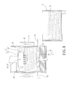
- FIG. 8 is a cross sectional view of an apparatus for producing microparticles of another embodiment including a collection tank according to the present disclosure.
- FIG. 9 is a partial, enlarged view of extension tubes of a nozzle for producing microparticles of an embodiment according to the present disclosure.
- FIG. 10 is a partial, enlarged view of an extension tube of a nozzle for producing microparticles of another embodiment according to the present disclosure.
- FIG. 11 is a cross sectional view of an apparatus for producing microparticles of another embodiment according to the present disclosure.
- FIG. 12 is a diagrammatic view of a microparticle product produced by the apparatus for producing microparticles of an embodiment according to the present disclosure, with the microparticle product including a pharmaceutically active ingredient.
- FIG. 13 is a diagrammatic view of a microparticle product produced by the apparatus for producing microparticles of an embodiment according to the present disclosure, with the microparticle product including micro gas bubbles.
- a nozzle for producing microparticles includes a nozzle body 1 having a fluid passageway 11 therein.
- a plurality of extension tubes 12 is communicated with an end of the fluid passageway 11 .
- Each extension tube 12 includes a distant end having an outlet port 121 and located distant to the fluid passageway 11 .
- the outlet ports 121 of the extension tubes 12 are spaced from each other.
- the extension tubes 12 can be parallel to each other.
- the outlet ports 121 of the extension tubes 12 are on the same plane.
- An oil phase fluid F 1 can be filled into the fluid passageway 11 , can flow along the fluid passageway 11 , and can flow out of the nozzle body 1 via the outlet ports 121 of the extension tubes 12 . Although the oil phase fluid F 1 will still withstand surface tension at each outlet port 121 , and since the surface area around an outer periphery of the outlet port 121 of each extension tube 12 is insufficient for the oil phase fluid F 1 to adhere, the oil phase fluid F 1 is difficult to accumulate on each outlet port 121 .
- the nozzle for producing microparticles can be used in an apparatus for producing microparticles including a fluid tank 2 , a fluid shear device 3 , and a temperature control system 4 .
- the extension tubes 12 of the nozzle body 1 extend into the fluid tank 2 .
- the fluid shear device 3 is mounted to the fluid tank 2 .
- the fluid shear device 3 can include a stirring device 31 or a supersonic wave generator 32 or both.
- the fluid shear device 3 includes both of the stirring device 31 and the supersonic wave generator 32 .
- the stirring device 31 is mounted in the fluid tank 2 .
- the supersonic wave generator 32 is mounted to an outer wall of the fluid tank 2 .
- the fluid tank 2 is mounted in the temperature control system 4 .
- the fluid tank 2 can receive a water phase fluid F 2 .
- the water phase fluid F 2 received in the fluid tank 2 includes a level defining a liquid level 21 .
- the extension tubes 12 of the nozzle body 1 extends into the fluid tank 2 , such that the outlet port 121 of each extension tube 12 is located under the liquid level 21 and a bottom 22 of the fluid tank 2 .
- the outlet ports 121 are located in the water phase fluid F 2 .
- the fluid shear device 3 is used to disturb the water phase fluid F 2 in the fluid tank 2 .
- the stirring device 31 can be driven by a motor to drive the water phase fluid F 2 to flow.
- the supersonic wave generator 32 can generate high frequency vibrations.
- the supersonic wave generator 32 is made of piezoelectric material and can include power capable of generating high frequency electrical energy.
- the piezoelectric material can turn the high frequency electrical energy into high frequency vibrations which are transmitted through the outer wall of the fluid tank 2 to the water phase fluid F 2 , causing vibrations of the water phase fluid F 2 .
- the temperature control system 4 can control the temperature of the water phase fluid F 2 to maintain the water phase fluid F 2 at a predetermined temperature.
- the oil phase fluid F 1 is produced by heating a polymer to a glass transition temperature (Tg) or by adding a small amount of organic solvent (such as ethyl acetate, ethyl acetate, etc.) into a polymer.
- the polymer can be a biodegradable polymer including aliphatic polyesters, aliphatic-aromatic copolyesters, polylactide-aliphatic copolyesters, polycaprolactone, polyglutamic acid, poly-hydroxy acid ester, or polylactide. More specifically, aliphatic polyesters can be polyglycolic acid, polybutylene succinate butanediamine, or polyethylene succinate.
- Aliphatic-aromatic copolyesters can be polyethylene terephthalate-polyoxyethylene.
- Polylactide-aliphatic copolyesters can be polylactic glycolic acid.
- the present disclosure is not limited to these.
- Other biodegradable polymers used as drug microcarriers can be used as the polymer.
- the polymer is preferably polycaprolactone, polylactide, or polylactic glycolic acid.
- Polycaprolactone has excellent biocompatibility and miscibility and has excellent molecular flowability in the organism due to a low glass transition temperature, presenting excellent permeability for active pharmaceutical ingredients having a low molecular weight.
- a method for producing microparticles of an embodiment according to the present disclosure can be carried out by the apparatus for producing microparticles.
- the method for producing microparticles of this embodiment includes filling the water phase fluid F 2 into the fluid tank F 2 .
- the temperature control system 4 is activated to maintain the water phase fluid F 2 at a predetermined temperature.
- the predetermined temperature is equal to or lower than the glass transition temperature (Tg) of the oil phase fluid F 1 .
- the water phase can be, but is not limited to, a 1-15% polyvinyl acetate (PVA) solution.
- PVA polyvinyl acetate
- the oil phase fluid F 1 is filled into the fluid passageway 11 of the nozzle body 1 and flows out of the nozzle body 1 via the outlet port 121 of each extension tube 12 to generate a continuous oil phase fluid F 1 .
- the stirring device 31 is driven to rotate, and the supersonic wave generator 32 is activated.
- the fluid passageway 11 is pressurized to make the oil phase fluid F 1 flow through the fluid passageway 11 at a certain speed and to continuously drive the oil phase fluid F 1 into the water phase fluid F 2 via each outlet port 121 , thereby generating the continuous oil phase fluid F 1 .
- the stirring device 31 drives the water phase fluid F 2 to flow, thereby using the shear force of the flowing water phase fluid F 2 to interrupt the continuous oil phase fluid F 1 flowing out of each outlet port 121 , such that the oil phase fluid F 1 forms microdroplets.
- the supersonic wave generator 32 makes the water phase fluid F 2 vibrate to interrupt the continuous oil phase fluid F 1 flowing out of each outlet port 121 , such that the oil phase fluid F 1 forms microdroplets.
- the water phase fluid F 2 received in the fluid tank 2 envelops the outer layers of the microdroplets (namely, emulsification) to assist in curing and shaping of the microdroplets, thereby forming semi-products S of microparticles in the fluid tank 2 , as shown in FIG. 6 .
- Each semi-product S includes an inner layer S 1 formed by the oil phase fluid F 1 and an outer layer S 2 formed by the water phase fluid F 2 .
- the semi-products S are collected, and the outer layers S 2 formed by the water phase fluid F 2 are removed to form microparticle products M each of which is formed by the inner layer S 1 formed by the oil phase fluid F 1 (see FIG. 7 ).
- the semi-products S are dried (such as by hot air) to evaporate the outer layers S 2 .
- the semi-products S are washed by an aqueous solution to remove the outer layers S 2 , forming microparticle products M merely formed by the oil phase fluid F 1 .
- the worker can collect the semi-products S by using the fluid tank 2 . Alternatively, as shown in FIGS.
- an inlet pipe 23 and an outlet pipe 24 are coupled to the fluid tank 2 and extend through a wall of the fluid tank 2 .
- the outlet pipe 24 is mounted to a position adjacent to the bottom 22 .
- the apparatus for producing microparticles can further include a collection tank 5 intercommunicated with the outlet pipe 24 of the fluid tank 2 .
- the water phase fluid F 2 along with the semi-products S can flow through the outlet pipe 24 into the collection tank 5 , and a worker can collect the semi-products S in the collection tank 5 .
- the water phase fluid F 2 can be filled into the inlet pipe 23 to maintain the water phase fluid F 2 in the fluid tank 2 at the liquid level 21 , thereby assuring that the outlet port 121 of each extension tube 12 is located in the water phase fluid F 2 .
- the conventional nozzle 9 relies on surface tension to form microdroplets on the openings 92 , leading to diverse diameters of the microparticles.
- the nozzle, apparatus, and method according to the present disclosure use the nozzle body 1 to generate continuous oil phase fluid F 1 and use the shear force or vibrations of the water phase fluid F 2 to interrupt the continuous oil phase fluids F 1 , thereby forming the microparticle products M. Since the surface area around the outer periphery of the outlet port 121 of each extension tube 12 is insufficient for the oil phase fluid F 1 to adhere, the oil phase fluid F 1 is difficult to accumulate on each outlet port 121 . As a result, the microparticle products M have more uniform diameters, increasing the uniformity of the microparticles.
- the apparatus and method for producing microparticles according to the present disclosure use the shear force or vibrations of the water phase fluid F 2 to interrupt the continuous oil phase fluids F 1 , the rotational speed of the stirring device 31 can be adjusted to control the shear force of the water phase fluid F 2 .
- the frequency and amplitude of the supersonic wave generator 32 can be adjusted to control the vibrations of the water phase fluid F 2 .
- precise control of the diameters of the microparticle products M can be achieved.
- the rotational speed of the stirring device 31 or the amplitude of the supersonic wave generator 32 can be increased to increase the shear force generated by the water phase fluid F 2 , assuring that the water phase fluid F 2 can effectively interrupt the oil phase fluid F 1 , and avoiding the diameters of the microparticle products M from being adversely affected by the concentration of the oil phase fluid F 1 and thereby precisely controlling the diameters of the microparticle products M.
- the nozzle, apparatus, and method for producing microparticles according to the present disclosure can increase the control precision of the diameters of the microparticles and can be applied in high-concentration oil phase fluid F 1 (e.g., the concentration of the polymer material is larger than 9 wt %), broadening the applications.
- high-concentration oil phase fluid F 1 e.g., the concentration of the polymer material is larger than 9 wt %)
- the nozzle, apparatus and method for producing microparticles according to the present disclosure make the oil phase fluid F 1 flow out of the nozzle body 1 via the outlet port 121 of each extension tube 12 , such that the oil phase fluid F 1 is able to flow through the fluid passageway 11 and each extension tube 12 at a certain speed to produce continuous oil phase fluids F 1 , thereby forming the microparticle products M.
- the nozzle, apparatus, and method for producing microparticles according to the present disclosure permit the oil phase fluid F 1 to flow out of the nozzle body 1 at a faster speed to reduce the time for producing the microparticles, increasing the productivity of the microparticles.
- the apparatus and method for producing microparticles according to the present disclosure can assure each microdroplet is enveloped by the water phase fluid F 2 , increasing the yield of microparticles.
- each extension tube 12 has a diameter D 1 .
- Each extension tube 12 includes a tubular wall having a thickness D 2 .
- the thickness D 2 is preferably smaller than the diameter D 1 to reduce the surface area of each extension tube 12 at the outer periphery of the outlet port 121 .
- the oil phase fluid F 1 is difficult to accumulate in each outlet port 121 , thereby reducing adverse influence on the diameters of the microparticle products M by the surface tension.
- each extension tube 12 having the outlet port 121 can be a flat end.
- the distant end of each extension tube 12 having the outlet port 121 is an inclined end.
- the distant end of each extension tube 12 having the outlet port 121 includes a layer of hydrophobic material.
- the hydrophobic material can be, but is not limited to, silicon dioxide (SiO2) or titanium dioxide (TiO2).
- the layer of hydrophobic material can be, but is not limited to, disposed on the distant end of each extension tube 12 having the outlet port 121 by plating.
- the oil phase fluid F 1 comes in contact with the layer of hydrophobic material when flowing out of each outlet port 121 , such that the oil phase fluid F 1 is difficult to adhere to each extension tube 12 , reliably preventing the oil phase fluid F 1 from accumulating on each outlet port 121 to more effectively reduce the adverse influence on the diameters of the microparticle products M by the surface tension.
- the diameter D 1 decides the flow of the continuous oil phase fluid F 1 flowing out of each outlet port 121 to thereby control the diameter of the microparticle products M.
- the diameter D 1 corresponds to the diameter of the microparticle products M to be produced.
- the diameter D 1 can be designed to be about 100 ⁇ m.
- the diameter D 1 can be designed to be about 5 ⁇ m.
- the embodiments of the present disclosure are not limited to produce microparticle products M having diameters the same as the diameter D 1 and can produce microparticle products M having a diameter smaller than the diameter D 1 . Accordingly, although the microparticle products M in the embodiments are of microscale, the present disclosure can make the diameters of the microparticle products M reach nanoscale.
- the nozzle body 1 of the nozzle of an embodiment according to the present disclosure includes a core 1 a and a seat 1 b .
- the core 1 a is detachably mounted to the seat 1 b .
- the core 1 a includes an assembly portion 13 for detachable coupling with the seat 1 b .
- the assembly portion 13 is a screw hole, and a fastener 14 extends through the assembly portion 13 to fix the core 1 a to the seat 1 b .
- the passageway 11 extends through the seat 1 b .
- the extension tubes 12 are mounted to the core 1 a .
- the nozzle for producing microparticles of an embodiment according to the present disclosure includes the core 1 a detachably mounted to the seat 1 b , the nozzle can be used to produce microparticle products M of a different diameter by changing a core 1 a having a different diameter D 1 in the outlet ports 121 , thereby increasing utility of the nozzle for producing microparticles.
- two adjacent extension tubes 12 of the nozzle body 1 have a minimum spacing D 3 therebetween (see FIG. 9 ).
- the minimum spacing D 3 is preferably larger than the diameter D 1 to avoid mixing of continuous oil phase fluids F 1 flowing out of adjacent extension tubes 12 .
- the method for producing microparticles of an embodiment according to the present disclosure pressurizes the passageway 11 to make the oil phase fluid F 1 flow through the passageway 11 at a certain speed, such that the oil phase fluid F 1 is continuously driven into the water phase fluid F 2 via each outlet port 121 .
- the nozzle body 1 extends from a horizontal, upper position of the fluid tank 2 into the fluid tank 2 of the apparatus for producing microparticles.
- the nozzle body 1 extends from a horizontal, lower position of the fluid tank 2 into the fluid tank 2 .
- the nozzle body 1 can extend from another horizontal position of the fluid tank 2 into the fluid tank 2 .
- the relative position between the nozzle body 1 and the fluid tank 2 is not limited in the present disclosure as long as the extension tubes 12 of the nozzle body 1 extend into the fluid tank 2 and the outlet port 121 of each extension tube 12 is located under the liquid level 21 to permit the oil phase fluid F 1 to be driven into the water phase fluid F 2 .
- the temperature control system 4 can be a heating coil and is coupled to the outer wall of the fluid tank 2 .
- the temperature control system 4 can heat the water phase fluid F 2 via the outer wall of the fluid tank 2 to maintain the water phase fluid F 2 at the predetermined temperature.
- the temperature control system 4 can be a thermostat box, and the fluid tank 2 can be mounted in the temperature control system 4 .
- the temperature control system 4 can also maintain the water phase fluid F 2 at the predetermined temperature.
- the temperature control system 4 is activated to maintain water phase fluid F 2 at the predetermined temperature, such that the temperature of the water phase fluid F 2 can assist in curing and shaping of the microdroplets while the oil phase fluid F 1 are forming the microdroplets.
- the oil phase fluid F 1 can be produced by adding a small amount of organic solvent into a polymer.
- curing and shaping of the microdroplets formed by the oil phase fluid F 1 may not be significantly related to the temperature of the water phase fluid F 2 . Consequently, the temperature control system 4 does not have to be activated in the method for producing microparticles in some embodiments according to the present disclosure.
- the worker can change the composition of the oil phase fluid F 1 to form the microparticle products M shown in FIG. 12 .
- the oil phase fluid F 1 can be a biodegradable polymer mixed with an active pharmaceutical ingredient M 1 by emulsification, such that each microparticle product M contains the active pharmaceutical ingredient M 1 .
- a slow releasing effect of the active pharmaceutical ingredient M 1 is achieved by enveloping of the biodegradable polymer.
- microparticle products M shown in FIG. 13 can be obtained.
- Each microparticle product M contains a plurality of micro gas bubbles M 2 to increase the drug releasing effect of the microparticle products M.
- the micro gas bubbles M 2 in the form of voids in the microparticles provide a room for adherence of bacteria, increasing the number of adhered bacteria.
- the nozzle, method, and apparatus for producing microparticles use the nozzle body 1 to generate continuous oil phase fluids F 1 and use the fluid shear device 3 to disturb the water phase fluid F 2 in the fluid tank 2 .
- the shear force or vibration of the water phase fluid F 2 is used to interrupt the continuous oil phase fluids F 1 to thereby form the semi-products of microdroplets and subsequently forming the microparticle products.
- the nozzle body 1 includes extension tubes 12 to prevent the oil phase fluid F 1 from accumulating on each outlet port 121 , such that the produced microparticle products M have more uniform diameters, reliably increasing the uniformity of microparticles.
- the apparatus and method for producing microparticles according to the present disclosure use the shear force or vibrations of the water phase fluid F 2 to interrupt the continuous oil phase fluids F 1 , the rotational speed of the stirring device 31 can be adjusted to control the shear force of the water phase fluid F 2 .
- the frequency and amplitude of the supersonic wave generator 32 can be adjusted to control the vibrations of the water phase fluid F 2 . Accordingly, precise control of the diameters of the microparticle products M can be achieved.
- the present disclosure is suitable for producing microparticles from a high-concentration oil phase fluid F 1 , reliably increasing the control precision of the diameters of the microparticles while broadening the applications of the apparatus and method for producing microparticles.
- the nozzle, apparatus, and method for producing microparticles make the oil phase fluid F 1 continuously flow out of the nozzle body 1 at a faster speed, reducing the time for producing microparticles and reliably increasing the productivity of microparticles.
- the apparatus and method for producing microparticles use the stirring device 31 to drive the water phase fluid F 2 to flow or use the supersonic wave generator 32 to vibrate the water phase fluid F 2 , such that the microdroplets formed by the oil phase fluid F 1 are prevented from aggregating in the water phase fluid F 2 to assure each microdroplet is enveloped and shaped by the water phase fluid F 2 , increasing the yield of the microparticles.
Landscapes
- Chemical & Material Sciences (AREA)
- Organic Chemistry (AREA)
- Engineering & Computer Science (AREA)
- Chemical Kinetics & Catalysis (AREA)
- Health & Medical Sciences (AREA)
- Dispersion Chemistry (AREA)
- Mechanical Engineering (AREA)
- Bioinformatics & Cheminformatics (AREA)
- Medicinal Chemistry (AREA)
- Pharmacology & Pharmacy (AREA)
- Epidemiology (AREA)
- Life Sciences & Earth Sciences (AREA)
- Animal Behavior & Ethology (AREA)
- General Health & Medical Sciences (AREA)
- Public Health (AREA)
- Veterinary Medicine (AREA)
- Manufacturing Of Micro-Capsules (AREA)
- Nozzles (AREA)
- Physical Or Chemical Processes And Apparatus (AREA)
Applications Claiming Priority (3)
| Application Number | Priority Date | Filing Date | Title |
|---|---|---|---|
| TW105134449 | 2016-10-25 | ||
| TW105134449A | 2016-10-25 | ||
| TW105134449A TWI643680B (zh) | 2016-10-25 | 2016-10-25 | 微粒噴頭 |
Publications (2)
| Publication Number | Publication Date |
|---|---|
| US20180110736A1 US20180110736A1 (en) | 2018-04-26 |
| US10117835B2 true US10117835B2 (en) | 2018-11-06 |
Family
ID=61971607
Family Applications (1)
| Application Number | Title | Priority Date | Filing Date |
|---|---|---|---|
| US15/378,292 Active 2037-01-10 US10117835B2 (en) | 2016-10-25 | 2016-12-14 | Nozzle, apparatus, and method for producing microparticles |
Country Status (3)
| Country | Link |
|---|---|
| US (1) | US10117835B2 (ja) |
| JP (1) | JP2018069222A (ja) |
| TW (1) | TWI643680B (ja) |
Cited By (1)
| Publication number | Priority date | Publication date | Assignee | Title |
|---|---|---|---|---|
| CN110871523A (zh) * | 2019-11-24 | 2020-03-10 | 六安丰恺尼机电科技有限公司 | 一种对塑料颗粒进行干燥的组件 |
Families Citing this family (3)
| Publication number | Priority date | Publication date | Assignee | Title |
|---|---|---|---|---|
| US10821413B2 (en) | 2017-12-22 | 2020-11-03 | Metal Industries Research & Development Centre | Microparticle forming device |
| CN112694654A (zh) * | 2020-12-22 | 2021-04-23 | 安徽杰蓝特新材料有限公司 | 一种应用于pe给水管材的抗菌色母粒及其制备方法 |
| CN113524660B (zh) * | 2021-08-10 | 2022-12-13 | 烟台液秀生物科技有限公司 | 一种高通量阵列式3d液滴打印方法 |
Citations (18)
| Publication number | Priority date | Publication date | Assignee | Title |
|---|---|---|---|---|
| US1637377A (en) * | 1926-01-22 | 1927-08-02 | Armour & Co | Pellet-forming apparatus |
| US3123855A (en) * | 1961-04-28 | 1964-03-10 | Apparatus for converting fusible materials | |
| JPS4868474A (ja) | 1971-12-21 | 1973-09-18 | ||
| US3933955A (en) * | 1970-12-17 | 1976-01-20 | Mcdonnell Douglas Corporation | Process for producing microspheres |
| JPS5335673A (en) | 1976-09-16 | 1978-04-03 | Mitsui Mining & Smelting Co | Process for producing liquid drops |
| JPS58210072A (ja) | 1982-05-18 | 1983-12-07 | チバ―ガイギ アクチエンゲゼルシヤフト | 塩化シアヌ−ルの水中懸濁物の製造または塩化シアヌ−ルとアンモニアまたはアミンとの反応のための方法および装置 |
| JPS61137836A (ja) | 1984-12-10 | 1986-06-25 | Kawasaki Kasei Chem Ltd | 1,4,4a,9a−テトラヒドロアントラキノン類の造粒方法 |
| JPH05177157A (ja) | 1991-12-26 | 1993-07-20 | Kobe Steel Ltd | マイクロカプセルの製造方法 |
| JPH0751343A (ja) | 1993-07-08 | 1995-02-28 | Rhone Poulenc Nutrition Animal | 小球体の製造方法 |
| US5882680A (en) * | 1995-12-07 | 1999-03-16 | Freund Industrial Co., Ltd. | Seamless capsule and method of manufacturing the same |
| JP2003311944A (ja) | 2002-04-23 | 2003-11-06 | Dainippon Printing Co Ltd | 微細パターンの形成方法 |
| US6998074B1 (en) * | 2002-08-30 | 2006-02-14 | Microfab Technologies, Inc. | Method for forming polymer microspheres |
| US20070056637A1 (en) * | 2003-10-16 | 2007-03-15 | Kazutoshi Okubo | Dripping nozzle device, device for recovering feedstock liquid, device for supplying a feedstock liquid, device for solidifying the surfaces of drops, device for circulation aqueous ammonia solution, and apparatus for droducing ammonium diuranate particles |
| US20100237523A1 (en) * | 2007-10-23 | 2010-09-23 | Koninklijke Philips Electronics N.V. | Methods for preparing polymer microparticles |
| WO2012100205A2 (en) | 2011-01-21 | 2012-07-26 | Biodot, Inc. | Piezoelectric dispenser with a longitudinal transducer and replaceable capillary tube |
| JP2012250476A (ja) | 2011-06-03 | 2012-12-20 | Ricoh Co Ltd | 液滴吐出ヘッドの製造方法及びノズル部材 |
| CN205235997U (zh) | 2015-12-15 | 2016-05-18 | 浙江大学 | 基于集成微通道的单组份/多组份液滴制备装置 |
| US20170101514A1 (en) * | 2014-03-26 | 2017-04-13 | Kaneka Corporation | Method for manufacturing coagulated particles from latex prepared by emulsion polymerization, aggregates from latex prepared by emulsion polymerization, and coagulated particles from latex prepared by emulsion polymerization |
-
2016
- 2016-10-25 TW TW105134449A patent/TWI643680B/zh active
- 2016-12-14 US US15/378,292 patent/US10117835B2/en active Active
- 2016-12-22 JP JP2016248906A patent/JP2018069222A/ja active Pending
Patent Citations (19)
| Publication number | Priority date | Publication date | Assignee | Title |
|---|---|---|---|---|
| US1637377A (en) * | 1926-01-22 | 1927-08-02 | Armour & Co | Pellet-forming apparatus |
| US3123855A (en) * | 1961-04-28 | 1964-03-10 | Apparatus for converting fusible materials | |
| US3933955A (en) * | 1970-12-17 | 1976-01-20 | Mcdonnell Douglas Corporation | Process for producing microspheres |
| JPS4868474A (ja) | 1971-12-21 | 1973-09-18 | ||
| JPS5335673A (en) | 1976-09-16 | 1978-04-03 | Mitsui Mining & Smelting Co | Process for producing liquid drops |
| JPS58210072A (ja) | 1982-05-18 | 1983-12-07 | チバ―ガイギ アクチエンゲゼルシヤフト | 塩化シアヌ−ルの水中懸濁物の製造または塩化シアヌ−ルとアンモニアまたはアミンとの反応のための方法および装置 |
| JPS61137836A (ja) | 1984-12-10 | 1986-06-25 | Kawasaki Kasei Chem Ltd | 1,4,4a,9a−テトラヒドロアントラキノン類の造粒方法 |
| JPH05177157A (ja) | 1991-12-26 | 1993-07-20 | Kobe Steel Ltd | マイクロカプセルの製造方法 |
| JPH0751343A (ja) | 1993-07-08 | 1995-02-28 | Rhone Poulenc Nutrition Animal | 小球体の製造方法 |
| US5492701A (en) | 1993-07-08 | 1996-02-20 | Rhone-Poulenc Nutrition Animale | Process for the preparation of spherules |
| US5882680A (en) * | 1995-12-07 | 1999-03-16 | Freund Industrial Co., Ltd. | Seamless capsule and method of manufacturing the same |
| JP2003311944A (ja) | 2002-04-23 | 2003-11-06 | Dainippon Printing Co Ltd | 微細パターンの形成方法 |
| US6998074B1 (en) * | 2002-08-30 | 2006-02-14 | Microfab Technologies, Inc. | Method for forming polymer microspheres |
| US20070056637A1 (en) * | 2003-10-16 | 2007-03-15 | Kazutoshi Okubo | Dripping nozzle device, device for recovering feedstock liquid, device for supplying a feedstock liquid, device for solidifying the surfaces of drops, device for circulation aqueous ammonia solution, and apparatus for droducing ammonium diuranate particles |
| US20100237523A1 (en) * | 2007-10-23 | 2010-09-23 | Koninklijke Philips Electronics N.V. | Methods for preparing polymer microparticles |
| WO2012100205A2 (en) | 2011-01-21 | 2012-07-26 | Biodot, Inc. | Piezoelectric dispenser with a longitudinal transducer and replaceable capillary tube |
| JP2012250476A (ja) | 2011-06-03 | 2012-12-20 | Ricoh Co Ltd | 液滴吐出ヘッドの製造方法及びノズル部材 |
| US20170101514A1 (en) * | 2014-03-26 | 2017-04-13 | Kaneka Corporation | Method for manufacturing coagulated particles from latex prepared by emulsion polymerization, aggregates from latex prepared by emulsion polymerization, and coagulated particles from latex prepared by emulsion polymerization |
| CN205235997U (zh) | 2015-12-15 | 2016-05-18 | 浙江大学 | 基于集成微通道的单组份/多组份液滴制备装置 |
Cited By (1)
| Publication number | Priority date | Publication date | Assignee | Title |
|---|---|---|---|---|
| CN110871523A (zh) * | 2019-11-24 | 2020-03-10 | 六安丰恺尼机电科技有限公司 | 一种对塑料颗粒进行干燥的组件 |
Also Published As
| Publication number | Publication date |
|---|---|
| JP2018069222A (ja) | 2018-05-10 |
| US20180110736A1 (en) | 2018-04-26 |
| TW201815481A (zh) | 2018-05-01 |
| TWI643680B (zh) | 2018-12-11 |
Similar Documents
| Publication | Publication Date | Title |
|---|---|---|
| US10117835B2 (en) | Nozzle, apparatus, and method for producing microparticles | |
| KR100867392B1 (ko) | 마이크로입자 | |
| Liu et al. | On the spray drying of uniform functional microparticles | |
| Chong et al. | Advances in fabricating double-emulsion droplets and their biomedical applications | |
| Tran et al. | Why and how to prepare biodegradable, monodispersed, polymeric microparticles in the field of pharmacy? | |
| Spyropoulos et al. | Advances in membrane emulsification. Part A: recent developments in processing aspects and microstructural design approaches | |
| Dalmoro et al. | Intensifying the microencapsulation process: Ultrasonic atomization as an innovative approach | |
| TW553770B (en) | Spray drying apparatus, secondary drying apparatus and methods of making particles | |
| CN101652170B (zh) | 用于喷雾干燥的方法和设备以及使用所述方法制备的粉末 | |
| CN101574305B (zh) | 振动破碎式微丸机 | |
| CN100556530C (zh) | 制备微粒的喷嘴及利用该喷嘴制备微胶囊粒子的方法 | |
| US10137090B2 (en) | Nozzle, apparatus, and method for producing microparticles | |
| CN102211008A (zh) | 可拆卸t型微通道装置及其制备单分散聚合物微球的方法 | |
| CN110538473B (zh) | 一种雾化盘、喷雾干燥雾化器及其雾化高粘度物料的方法 | |
| CA2315684A1 (en) | Apparatus for mixing and subsequent atomization of liquids | |
| Zhu et al. | Free‐Boundary Microfluidic Platform for Advanced Materials Manufacturing and Applications | |
| Rezvanpour et al. | Enhancement of particle collection efficiency in electrohydrodynamic atomization process for pharmaceutical particle fabrication | |
| JP4051075B2 (ja) | シームレスカプセル製造方法、シームレスカプセル製造装置及びシームレスカプセル | |
| CN110352092B (zh) | 用于生产粉状聚合物的设备和方法 | |
| TWI660789B (zh) | 微粒成形裝置及其微粒成形方法 | |
| US20180111106A1 (en) | Method for Producing Microparticles | |
| CN108608600B (zh) | 微粒成型装置及其微粒成型方法 | |
| TWI621481B (zh) | 微粒噴頭、微粒成形裝置及其微粒成形方法 | |
| CN214440111U (zh) | 高速旋转雾化器用高效雾化盘 | |
| Demont et al. | 9 Microencapsulation by |
Legal Events
| Date | Code | Title | Description |
|---|---|---|---|
| AS | Assignment |
Owner name: METAL INDUSTRIES RESEARCH & DEVELOPMENT CENTRE, TA Free format text: ASSIGNMENT OF ASSIGNORS INTEREST;ASSIGNORS:HUNG, CHENG-HAN;LIU, ZONG-HSIN;LIN, YING-CHIEH;AND OTHERS;SIGNING DATES FROM 20161130 TO 20161201;REEL/FRAME:040731/0640 |
|
| STCF | Information on status: patent grant |
Free format text: PATENTED CASE |
|
| MAFP | Maintenance fee payment |
Free format text: PAYMENT OF MAINTENANCE FEE, 4TH YEAR, LARGE ENTITY (ORIGINAL EVENT CODE: M1551); ENTITY STATUS OF PATENT OWNER: LARGE ENTITY Year of fee payment: 4 |