US10071747B2 - System for a vehicle - Google Patents
System for a vehicle Download PDFInfo
- Publication number
- US10071747B2 US10071747B2 US14/654,484 US201314654484A US10071747B2 US 10071747 B2 US10071747 B2 US 10071747B2 US 201314654484 A US201314654484 A US 201314654484A US 10071747 B2 US10071747 B2 US 10071747B2
- Authority
- US
- United States
- Prior art keywords
- workload
- circuit
- mode
- user
- image
- Prior art date
- Legal status (The legal status is an assumption and is not a legal conclusion. Google has not performed a legal analysis and makes no representation as to the accuracy of the status listed.)
- Active, expires
Links
Images


Classifications
-
- B—PERFORMING OPERATIONS; TRANSPORTING
- B60—VEHICLES IN GENERAL
- B60W—CONJOINT CONTROL OF VEHICLE SUB-UNITS OF DIFFERENT TYPE OR DIFFERENT FUNCTION; CONTROL SYSTEMS SPECIALLY ADAPTED FOR HYBRID VEHICLES; ROAD VEHICLE DRIVE CONTROL SYSTEMS FOR PURPOSES NOT RELATED TO THE CONTROL OF A PARTICULAR SUB-UNIT
- B60W50/00—Details of control systems for road vehicle drive control not related to the control of a particular sub-unit, e.g. process diagnostic or vehicle driver interfaces
- B60W50/08—Interaction between the driver and the control system
- B60W50/10—Interpretation of driver requests or demands
-
- B—PERFORMING OPERATIONS; TRANSPORTING
- B60—VEHICLES IN GENERAL
- B60K—ARRANGEMENT OR MOUNTING OF PROPULSION UNITS OR OF TRANSMISSIONS IN VEHICLES; ARRANGEMENT OR MOUNTING OF PLURAL DIVERSE PRIME-MOVERS IN VEHICLES; AUXILIARY DRIVES FOR VEHICLES; INSTRUMENTATION OR DASHBOARDS FOR VEHICLES; ARRANGEMENTS IN CONNECTION WITH COOLING, AIR INTAKE, GAS EXHAUST OR FUEL SUPPLY OF PROPULSION UNITS IN VEHICLES
- B60K35/00—Instruments specially adapted for vehicles; Arrangement of instruments in or on vehicles
- B60K35/10—Input arrangements, i.e. from user to vehicle, associated with vehicle functions or specially adapted therefor
-
- B—PERFORMING OPERATIONS; TRANSPORTING
- B60—VEHICLES IN GENERAL
- B60K—ARRANGEMENT OR MOUNTING OF PROPULSION UNITS OR OF TRANSMISSIONS IN VEHICLES; ARRANGEMENT OR MOUNTING OF PLURAL DIVERSE PRIME-MOVERS IN VEHICLES; AUXILIARY DRIVES FOR VEHICLES; INSTRUMENTATION OR DASHBOARDS FOR VEHICLES; ARRANGEMENTS IN CONNECTION WITH COOLING, AIR INTAKE, GAS EXHAUST OR FUEL SUPPLY OF PROPULSION UNITS IN VEHICLES
- B60K35/00—Instruments specially adapted for vehicles; Arrangement of instruments in or on vehicles
- B60K35/20—Output arrangements, i.e. from vehicle to user, associated with vehicle functions or specially adapted therefor
- B60K35/21—Output arrangements, i.e. from vehicle to user, associated with vehicle functions or specially adapted therefor using visual output, e.g. blinking lights or matrix displays
- B60K35/213—Virtual instruments
-
- B—PERFORMING OPERATIONS; TRANSPORTING
- B60—VEHICLES IN GENERAL
- B60K—ARRANGEMENT OR MOUNTING OF PROPULSION UNITS OR OF TRANSMISSIONS IN VEHICLES; ARRANGEMENT OR MOUNTING OF PLURAL DIVERSE PRIME-MOVERS IN VEHICLES; AUXILIARY DRIVES FOR VEHICLES; INSTRUMENTATION OR DASHBOARDS FOR VEHICLES; ARRANGEMENTS IN CONNECTION WITH COOLING, AIR INTAKE, GAS EXHAUST OR FUEL SUPPLY OF PROPULSION UNITS IN VEHICLES
- B60K35/00—Instruments specially adapted for vehicles; Arrangement of instruments in or on vehicles
- B60K35/20—Output arrangements, i.e. from vehicle to user, associated with vehicle functions or specially adapted therefor
- B60K35/21—Output arrangements, i.e. from vehicle to user, associated with vehicle functions or specially adapted therefor using visual output, e.g. blinking lights or matrix displays
- B60K35/23—Head-up displays [HUD]
-
- B—PERFORMING OPERATIONS; TRANSPORTING
- B60—VEHICLES IN GENERAL
- B60K—ARRANGEMENT OR MOUNTING OF PROPULSION UNITS OR OF TRANSMISSIONS IN VEHICLES; ARRANGEMENT OR MOUNTING OF PLURAL DIVERSE PRIME-MOVERS IN VEHICLES; AUXILIARY DRIVES FOR VEHICLES; INSTRUMENTATION OR DASHBOARDS FOR VEHICLES; ARRANGEMENTS IN CONNECTION WITH COOLING, AIR INTAKE, GAS EXHAUST OR FUEL SUPPLY OF PROPULSION UNITS IN VEHICLES
- B60K35/00—Instruments specially adapted for vehicles; Arrangement of instruments in or on vehicles
- B60K35/20—Output arrangements, i.e. from vehicle to user, associated with vehicle functions or specially adapted therefor
- B60K35/28—Output arrangements, i.e. from vehicle to user, associated with vehicle functions or specially adapted therefor characterised by the type of the output information, e.g. video entertainment or vehicle dynamics information; characterised by the purpose of the output information, e.g. for attracting the attention of the driver
-
- B—PERFORMING OPERATIONS; TRANSPORTING
- B60—VEHICLES IN GENERAL
- B60K—ARRANGEMENT OR MOUNTING OF PROPULSION UNITS OR OF TRANSMISSIONS IN VEHICLES; ARRANGEMENT OR MOUNTING OF PLURAL DIVERSE PRIME-MOVERS IN VEHICLES; AUXILIARY DRIVES FOR VEHICLES; INSTRUMENTATION OR DASHBOARDS FOR VEHICLES; ARRANGEMENTS IN CONNECTION WITH COOLING, AIR INTAKE, GAS EXHAUST OR FUEL SUPPLY OF PROPULSION UNITS IN VEHICLES
- B60K35/00—Instruments specially adapted for vehicles; Arrangement of instruments in or on vehicles
- B60K35/20—Output arrangements, i.e. from vehicle to user, associated with vehicle functions or specially adapted therefor
- B60K35/29—Instruments characterised by the way in which information is handled, e.g. showing information on plural displays or prioritising information according to driving conditions
-
- B—PERFORMING OPERATIONS; TRANSPORTING
- B60—VEHICLES IN GENERAL
- B60K—ARRANGEMENT OR MOUNTING OF PROPULSION UNITS OR OF TRANSMISSIONS IN VEHICLES; ARRANGEMENT OR MOUNTING OF PLURAL DIVERSE PRIME-MOVERS IN VEHICLES; AUXILIARY DRIVES FOR VEHICLES; INSTRUMENTATION OR DASHBOARDS FOR VEHICLES; ARRANGEMENTS IN CONNECTION WITH COOLING, AIR INTAKE, GAS EXHAUST OR FUEL SUPPLY OF PROPULSION UNITS IN VEHICLES
- B60K35/00—Instruments specially adapted for vehicles; Arrangement of instruments in or on vehicles
- B60K35/60—Instruments characterised by their location or relative disposition in or on vehicles
-
- B—PERFORMING OPERATIONS; TRANSPORTING
- B60—VEHICLES IN GENERAL
- B60K—ARRANGEMENT OR MOUNTING OF PROPULSION UNITS OR OF TRANSMISSIONS IN VEHICLES; ARRANGEMENT OR MOUNTING OF PLURAL DIVERSE PRIME-MOVERS IN VEHICLES; AUXILIARY DRIVES FOR VEHICLES; INSTRUMENTATION OR DASHBOARDS FOR VEHICLES; ARRANGEMENTS IN CONNECTION WITH COOLING, AIR INTAKE, GAS EXHAUST OR FUEL SUPPLY OF PROPULSION UNITS IN VEHICLES
- B60K37/00—Dashboards
-
- B—PERFORMING OPERATIONS; TRANSPORTING
- B60—VEHICLES IN GENERAL
- B60Q—ARRANGEMENT OF SIGNALLING OR LIGHTING DEVICES, THE MOUNTING OR SUPPORTING THEREOF OR CIRCUITS THEREFOR, FOR VEHICLES IN GENERAL
- B60Q9/00—Arrangement or adaptation of signal devices not provided for in one of main groups B60Q1/00 - B60Q7/00, e.g. haptic signalling
- B60Q9/008—Arrangement or adaptation of signal devices not provided for in one of main groups B60Q1/00 - B60Q7/00, e.g. haptic signalling for anti-collision purposes
-
- B—PERFORMING OPERATIONS; TRANSPORTING
- B60—VEHICLES IN GENERAL
- B60R—VEHICLES, VEHICLE FITTINGS, OR VEHICLE PARTS, NOT OTHERWISE PROVIDED FOR
- B60R11/00—Arrangements for holding or mounting articles, not otherwise provided for
- B60R11/02—Arrangements for holding or mounting articles, not otherwise provided for for radio sets, television sets, telephones, or the like; Arrangement of controls thereof
- B60R11/0229—Arrangements for holding or mounting articles, not otherwise provided for for radio sets, television sets, telephones, or the like; Arrangement of controls thereof for displays, e.g. cathodic tubes
-
- G—PHYSICS
- G01—MEASURING; TESTING
- G01C—MEASURING DISTANCES, LEVELS OR BEARINGS; SURVEYING; NAVIGATION; GYROSCOPIC INSTRUMENTS; PHOTOGRAMMETRY OR VIDEOGRAMMETRY
- G01C21/00—Navigation; Navigational instruments not provided for in groups G01C1/00 - G01C19/00
- G01C21/26—Navigation; Navigational instruments not provided for in groups G01C1/00 - G01C19/00 specially adapted for navigation in a road network
- G01C21/34—Route searching; Route guidance
- G01C21/36—Input/output arrangements for on-board computers
- G01C21/3626—Details of the output of route guidance instructions
- G01C21/365—Guidance using head up displays or projectors, e.g. virtual vehicles or arrows projected on the windscreen or on the road itself
-
- G—PHYSICS
- G02—OPTICS
- G02B—OPTICAL ELEMENTS, SYSTEMS OR APPARATUS
- G02B27/00—Optical systems or apparatus not provided for by any of the groups G02B1/00 - G02B26/00, G02B30/00
- G02B27/01—Head-up displays
-
- G—PHYSICS
- G02—OPTICS
- G02B—OPTICAL ELEMENTS, SYSTEMS OR APPARATUS
- G02B27/00—Optical systems or apparatus not provided for by any of the groups G02B1/00 - G02B26/00, G02B30/00
- G02B27/01—Head-up displays
- G02B27/0101—Head-up displays characterised by optical features
-
- G—PHYSICS
- G06—COMPUTING OR CALCULATING; COUNTING
- G06F—ELECTRIC DIGITAL DATA PROCESSING
- G06F3/00—Input arrangements for transferring data to be processed into a form capable of being handled by the computer; Output arrangements for transferring data from processing unit to output unit, e.g. interface arrangements
- G06F3/01—Input arrangements or combined input and output arrangements for interaction between user and computer
- G06F3/011—Arrangements for interaction with the human body, e.g. for user immersion in virtual reality
- G06F3/013—Eye tracking input arrangements
-
- G—PHYSICS
- G06—COMPUTING OR CALCULATING; COUNTING
- G06F—ELECTRIC DIGITAL DATA PROCESSING
- G06F3/00—Input arrangements for transferring data to be processed into a form capable of being handled by the computer; Output arrangements for transferring data from processing unit to output unit, e.g. interface arrangements
- G06F3/01—Input arrangements or combined input and output arrangements for interaction between user and computer
- G06F3/017—Gesture based interaction, e.g. based on a set of recognized hand gestures
-
- G—PHYSICS
- G06—COMPUTING OR CALCULATING; COUNTING
- G06F—ELECTRIC DIGITAL DATA PROCESSING
- G06F3/00—Input arrangements for transferring data to be processed into a form capable of being handled by the computer; Output arrangements for transferring data from processing unit to output unit, e.g. interface arrangements
- G06F3/01—Input arrangements or combined input and output arrangements for interaction between user and computer
- G06F3/048—Interaction techniques based on graphical user interfaces [GUI]
- G06F3/0481—Interaction techniques based on graphical user interfaces [GUI] based on specific properties of the displayed interaction object or a metaphor-based environment, e.g. interaction with desktop elements like windows or icons, or assisted by a cursor's changing behaviour or appearance
-
- G—PHYSICS
- G08—SIGNALLING
- G08G—TRAFFIC CONTROL SYSTEMS
- G08G1/00—Traffic control systems for road vehicles
-
- G—PHYSICS
- G08—SIGNALLING
- G08G—TRAFFIC CONTROL SYSTEMS
- G08G1/00—Traffic control systems for road vehicles
- G08G1/09—Arrangements for giving variable traffic instructions
- G08G1/0962—Arrangements for giving variable traffic instructions having an indicator mounted inside the vehicle, e.g. giving voice messages
- G08G1/09623—Systems involving the acquisition of information from passive traffic signs by means mounted on the vehicle
-
- H—ELECTRICITY
- H04—ELECTRIC COMMUNICATION TECHNIQUE
- H04M—TELEPHONIC COMMUNICATION
- H04M1/00—Substation equipment, e.g. for use by subscribers
- H04M1/60—Substation equipment, e.g. for use by subscribers including speech amplifiers
- H04M1/6033—Substation equipment, e.g. for use by subscribers including speech amplifiers for providing handsfree use or a loudspeaker mode in telephone sets
- H04M1/6041—Portable telephones adapted for handsfree use
- H04M1/6075—Portable telephones adapted for handsfree use adapted for handsfree use in a vehicle
-
- H—ELECTRICITY
- H04—ELECTRIC COMMUNICATION TECHNIQUE
- H04M—TELEPHONIC COMMUNICATION
- H04M3/00—Automatic or semi-automatic exchanges
- H04M3/42—Systems providing special services or facilities to subscribers
- H04M3/54—Arrangements for diverting calls for one subscriber to another predetermined subscriber
- H04M3/543—Call deflection
-
- H04N13/0242—
-
- H04N13/0278—
-
- H04N13/0282—
-
- H04N13/0459—
-
- H—ELECTRICITY
- H04—ELECTRIC COMMUNICATION TECHNIQUE
- H04N—PICTORIAL COMMUNICATION, e.g. TELEVISION
- H04N13/00—Stereoscopic video systems; Multi-view video systems; Details thereof
- H04N13/20—Image signal generators
- H04N13/204—Image signal generators using stereoscopic image cameras
- H04N13/243—Image signal generators using stereoscopic image cameras using three or more two-dimensional [2D] image sensors
-
- H—ELECTRICITY
- H04—ELECTRIC COMMUNICATION TECHNIQUE
- H04N—PICTORIAL COMMUNICATION, e.g. TELEVISION
- H04N13/00—Stereoscopic video systems; Multi-view video systems; Details thereof
- H04N13/20—Image signal generators
- H04N13/275—Image signal generators from three-dimensional [3D] object models, e.g. computer-generated stereoscopic image signals
- H04N13/279—Image signal generators from three-dimensional [3D] object models, e.g. computer-generated stereoscopic image signals the virtual viewpoint locations being selected by the viewers or determined by tracking
-
- H—ELECTRICITY
- H04—ELECTRIC COMMUNICATION TECHNIQUE
- H04N—PICTORIAL COMMUNICATION, e.g. TELEVISION
- H04N13/00—Stereoscopic video systems; Multi-view video systems; Details thereof
- H04N13/20—Image signal generators
- H04N13/282—Image signal generators for generating image signals corresponding to three or more geometrical viewpoints, e.g. multi-view systems
-
- H—ELECTRICITY
- H04—ELECTRIC COMMUNICATION TECHNIQUE
- H04N—PICTORIAL COMMUNICATION, e.g. TELEVISION
- H04N13/00—Stereoscopic video systems; Multi-view video systems; Details thereof
- H04N13/30—Image reproducers
- H04N13/363—Image reproducers using image projection screens
-
- H—ELECTRICITY
- H04—ELECTRIC COMMUNICATION TECHNIQUE
- H04N—PICTORIAL COMMUNICATION, e.g. TELEVISION
- H04N9/00—Details of colour television systems
- H04N9/12—Picture reproducers
- H04N9/31—Projection devices for colour picture display, e.g. using electronic spatial light modulators [ESLM]
-
- H04W4/046—
-
- H—ELECTRICITY
- H04—ELECTRIC COMMUNICATION TECHNIQUE
- H04W—WIRELESS COMMUNICATION NETWORKS
- H04W4/00—Services specially adapted for wireless communication networks; Facilities therefor
- H04W4/16—Communication-related supplementary services, e.g. call-transfer or call-hold
-
- H—ELECTRICITY
- H04—ELECTRIC COMMUNICATION TECHNIQUE
- H04W—WIRELESS COMMUNICATION NETWORKS
- H04W4/00—Services specially adapted for wireless communication networks; Facilities therefor
- H04W4/30—Services specially adapted for particular environments, situations or purposes
- H04W4/40—Services specially adapted for particular environments, situations or purposes for vehicles, e.g. vehicle-to-pedestrians [V2P]
-
- H—ELECTRICITY
- H04—ELECTRIC COMMUNICATION TECHNIQUE
- H04W—WIRELESS COMMUNICATION NETWORKS
- H04W4/00—Services specially adapted for wireless communication networks; Facilities therefor
- H04W4/80—Services using short range communication, e.g. near-field communication [NFC], radio-frequency identification [RFID] or low energy communication
-
- B60K2350/1052—
-
- B60K2350/1072—
-
- B60K2350/1076—
-
- B60K2350/2052—
-
- B60K2350/2095—
-
- B—PERFORMING OPERATIONS; TRANSPORTING
- B60—VEHICLES IN GENERAL
- B60K—ARRANGEMENT OR MOUNTING OF PROPULSION UNITS OR OF TRANSMISSIONS IN VEHICLES; ARRANGEMENT OR MOUNTING OF PLURAL DIVERSE PRIME-MOVERS IN VEHICLES; AUXILIARY DRIVES FOR VEHICLES; INSTRUMENTATION OR DASHBOARDS FOR VEHICLES; ARRANGEMENTS IN CONNECTION WITH COOLING, AIR INTAKE, GAS EXHAUST OR FUEL SUPPLY OF PROPULSION UNITS IN VEHICLES
- B60K2360/00—Indexing scheme associated with groups B60K35/00 or B60K37/00 relating to details of instruments or dashboards
- B60K2360/146—Instrument input by gesture
-
- B—PERFORMING OPERATIONS; TRANSPORTING
- B60—VEHICLES IN GENERAL
- B60K—ARRANGEMENT OR MOUNTING OF PROPULSION UNITS OR OF TRANSMISSIONS IN VEHICLES; ARRANGEMENT OR MOUNTING OF PLURAL DIVERSE PRIME-MOVERS IN VEHICLES; AUXILIARY DRIVES FOR VEHICLES; INSTRUMENTATION OR DASHBOARDS FOR VEHICLES; ARRANGEMENTS IN CONNECTION WITH COOLING, AIR INTAKE, GAS EXHAUST OR FUEL SUPPLY OF PROPULSION UNITS IN VEHICLES
- B60K2360/00—Indexing scheme associated with groups B60K35/00 or B60K37/00 relating to details of instruments or dashboards
- B60K2360/16—Type of output information
-
- B—PERFORMING OPERATIONS; TRANSPORTING
- B60—VEHICLES IN GENERAL
- B60K—ARRANGEMENT OR MOUNTING OF PROPULSION UNITS OR OF TRANSMISSIONS IN VEHICLES; ARRANGEMENT OR MOUNTING OF PLURAL DIVERSE PRIME-MOVERS IN VEHICLES; AUXILIARY DRIVES FOR VEHICLES; INSTRUMENTATION OR DASHBOARDS FOR VEHICLES; ARRANGEMENTS IN CONNECTION WITH COOLING, AIR INTAKE, GAS EXHAUST OR FUEL SUPPLY OF PROPULSION UNITS IN VEHICLES
- B60K2360/00—Indexing scheme associated with groups B60K35/00 or B60K37/00 relating to details of instruments or dashboards
- B60K2360/18—Information management
- B60K2360/182—Distributing information between displays
-
- B—PERFORMING OPERATIONS; TRANSPORTING
- B60—VEHICLES IN GENERAL
- B60K—ARRANGEMENT OR MOUNTING OF PROPULSION UNITS OR OF TRANSMISSIONS IN VEHICLES; ARRANGEMENT OR MOUNTING OF PLURAL DIVERSE PRIME-MOVERS IN VEHICLES; AUXILIARY DRIVES FOR VEHICLES; INSTRUMENTATION OR DASHBOARDS FOR VEHICLES; ARRANGEMENTS IN CONNECTION WITH COOLING, AIR INTAKE, GAS EXHAUST OR FUEL SUPPLY OF PROPULSION UNITS IN VEHICLES
- B60K2360/00—Indexing scheme associated with groups B60K35/00 or B60K37/00 relating to details of instruments or dashboards
- B60K2360/20—Optical features of instruments
- B60K2360/27—Optical features of instruments using semi-transparent optical elements
-
- B—PERFORMING OPERATIONS; TRANSPORTING
- B60—VEHICLES IN GENERAL
- B60K—ARRANGEMENT OR MOUNTING OF PROPULSION UNITS OR OF TRANSMISSIONS IN VEHICLES; ARRANGEMENT OR MOUNTING OF PLURAL DIVERSE PRIME-MOVERS IN VEHICLES; AUXILIARY DRIVES FOR VEHICLES; INSTRUMENTATION OR DASHBOARDS FOR VEHICLES; ARRANGEMENTS IN CONNECTION WITH COOLING, AIR INTAKE, GAS EXHAUST OR FUEL SUPPLY OF PROPULSION UNITS IN VEHICLES
- B60K2360/00—Indexing scheme associated with groups B60K35/00 or B60K37/00 relating to details of instruments or dashboards
- B60K2360/20—Optical features of instruments
- B60K2360/33—Illumination features
- B60K2360/334—Projection means
-
- B—PERFORMING OPERATIONS; TRANSPORTING
- B60—VEHICLES IN GENERAL
- B60K—ARRANGEMENT OR MOUNTING OF PROPULSION UNITS OR OF TRANSMISSIONS IN VEHICLES; ARRANGEMENT OR MOUNTING OF PLURAL DIVERSE PRIME-MOVERS IN VEHICLES; AUXILIARY DRIVES FOR VEHICLES; INSTRUMENTATION OR DASHBOARDS FOR VEHICLES; ARRANGEMENTS IN CONNECTION WITH COOLING, AIR INTAKE, GAS EXHAUST OR FUEL SUPPLY OF PROPULSION UNITS IN VEHICLES
- B60K35/00—Instruments specially adapted for vehicles; Arrangement of instruments in or on vehicles
- B60K35/20—Output arrangements, i.e. from vehicle to user, associated with vehicle functions or specially adapted therefor
- B60K35/26—Output arrangements, i.e. from vehicle to user, associated with vehicle functions or specially adapted therefor using acoustic output
-
- G—PHYSICS
- G02—OPTICS
- G02B—OPTICAL ELEMENTS, SYSTEMS OR APPARATUS
- G02B27/00—Optical systems or apparatus not provided for by any of the groups G02B1/00 - G02B26/00, G02B30/00
- G02B27/01—Head-up displays
- G02B27/0101—Head-up displays characterised by optical features
- G02B2027/0138—Head-up displays characterised by optical features comprising image capture systems, e.g. camera
-
- G—PHYSICS
- G02—OPTICS
- G02B—OPTICAL ELEMENTS, SYSTEMS OR APPARATUS
- G02B27/00—Optical systems or apparatus not provided for by any of the groups G02B1/00 - G02B26/00, G02B30/00
- G02B27/01—Head-up displays
- G02B27/0101—Head-up displays characterised by optical features
- G02B2027/014—Head-up displays characterised by optical features comprising information/image processing systems
-
- G—PHYSICS
- G02—OPTICS
- G02B—OPTICAL ELEMENTS, SYSTEMS OR APPARATUS
- G02B27/00—Optical systems or apparatus not provided for by any of the groups G02B1/00 - G02B26/00, G02B30/00
- G02B27/01—Head-up displays
- G02B27/0101—Head-up displays characterised by optical features
- G02B2027/0141—Head-up displays characterised by optical features characterised by the informative content of the display
-
- G—PHYSICS
- G06—COMPUTING OR CALCULATING; COUNTING
- G06F—ELECTRIC DIGITAL DATA PROCESSING
- G06F2203/00—Indexing scheme relating to G06F3/00 - G06F3/048
- G06F2203/048—Indexing scheme relating to G06F3/048
- G06F2203/04804—Transparency, e.g. transparent or translucent windows
-
- H—ELECTRICITY
- H04—ELECTRIC COMMUNICATION TECHNIQUE
- H04N—PICTORIAL COMMUNICATION, e.g. TELEVISION
- H04N2101/00—Still video cameras
Definitions
- the present invention relates to a system for a vehicle and a method for controlling a head-up display for a vehicle.
- AWMSs to dynamically control the rate of messages from these in-vehicle systems.
- the driver's workload is estimated in several driving situations.
- a message controller determines the optimal delay times between messages and dynamically controls the rate of messages presented to the driver.
- the rate of messages is adapted to the driving conditions, e.g. speed and curvatures, and driver characteristics, e.g., age.
- AWMSs collect current driving information, such as steering wheel angle and lane position, and then use computational algorithms to directly estimate the current workload of the driver. To reduce the driver's workload, messages from in-vehicle systems are suppressed or messages are redirected into a voice mailbox when the driver's estimated mental workload is high.
- Multitasking information in driving is typically presented in a multimodal format: either through the visual (e.g., looking at a map or a display of a navigation system) or the auditory modality (e.g., listening to messages from cellular phones or warning systems).
- Drivers read directions for and the distance to the next turn (maneuver point) from the display (perceptual processing), perform mental calculations to decide whether and when to switch to a different lane (cognitive processing), and possibly engage the turning signal and turn the steering wheel (motor processing).
- the level of driver workload and performance can be estimated based on road situations, drivers' age, message properties from the in-vehicle systems change in terms of modalities, message difficulty, and motor execution time.
- Absolute and differential thresholds of the simulated workload can be set to determine the optimal design of the messages and whether the proposed design can produce a workload that is higher than the “redline”.
- GPS Global Positioning Systems
- the focus of AWMS is to reduce driver workload. It is suitable for non-urgent messages of in-vehicle systems when delaying messages for a few seconds is allowable, e.g., messages from e-mail systems and messages related to traffic congestion. For urgent messages that require immediate driver response, e.g. forward collision warning messages, no extra delays are allowed.
- Algorithms can manage messages with different priorities, including the order and length of these messages. Further driving conditions, such as traffic density, intersections, road curvature in the next few seconds, route planning and selections, and weather conditions may be added.
- the object of the invention is to improve a system for a vehicle.
- the system has a head-up display and a circuit, whereby the circuit is connected to the head-up display.
- the head-up display is configured to project an image onto the vehicle's front windshield or onto a separate combiner.
- the circuit is configured to output image data to the head-up display in order to generate the image.
- the image data have a set of objects which include messages for the user.
- the circuit is configured to determine the user's workload level based on a set of driving conditions.
- the circuit is configured, based on the level, to switch between at least one first workload mode and a second workload mode.
- the level assigned to the second workload mode is higher than the level assigned to the first workload mode.
- the circuit is configured in the second workload mode to reduce at least one object of the set, which is output in the first workload mode.
- Tests by the applicant have shown that a plurality of information can be displayed simultaneously to the driver in high resolution by the head-up display, without the driver having to look away from the traffic ahead to perceive the information.
- the driver's workload could be significantly reduced by a specific configuration of an adaptive workload management system by the intelligent reduction of the objects.
- the invention further has the object of providing an improved method for controlling a head-up display.
- the method has the steps:
- the circuit may be connected to the head-up display.
- the circuit may be configured to fade out the object and/or to make the object in the image smaller and/or to increase the transparency of the object and/or to move the object within the image away from a central position into a predetermined area.
- the object may be moved from a position in the main viewing direction of the driver towards a boundary, so that the object is not disturbing the driver while viewing the traffic in front.
- An uncritical area, the object may be moved to, is a lower edge of the image area, so that the drivers may see the object virtually before the engine bonnet of the vehicle.
- the circuit may be configured during or after the reduction to output the message associated with the object by means of another object in another display different from the front windshield.
- the circuit may be configured to identify an input by the user.
- the circuit may be configured, based on the input, to start an application program, whereby the object is associated with the application program.
- the circuit may be configured to prioritize the objects.
- the circuit may be configured to reduce first the object with the lowest priority in the second workload mode.
- the circuit may be configured to switch to a warning mode.
- the circuit may be configured to reduce at least one of the objects of the set in the warning mode and to output at least one warning object at least temporarily in the image data.
- FIG. 1 shows a schematic view of a vehicle interior
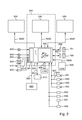
- FIG. 2 shows a schematic view of an infotainment system
- FIG. 3 shows a schematic view of an augmented reality
- FIG. 4 shows a further schematic view of an augmented reality
- FIG. 5 shows a further schematic view of an augmented reality
- FIG. 6 shows a further schematic view of an augmented reality
- FIG. 7 shows a further schematic view of an augmented reality
- FIG. 8 shows further schematic views of an augmented reality
- FIG. 9 shows a further schematic view of an augmented reality.
- FIG. 1 A view of a vehicle interior is shown schematically in FIG. 1 .
- An image 201 may be projected in a reflection area 299 onto a front windshield 110 of a vehicle 100 .
- the image 201 may be generated by a head-up display 200 .
- the head-up display 200 may also be referred to as head unit display.
- the driver who observes the traffic ahead through front windshield 110 , has the projected image 201 at least partially in his field of vision.
- large parts of image 201 may be made transparent or semitransparent, so that the driver can also easily see real objects or persons behind objects 210 , 211 , 212 , 213 of image 201 .
- Objects 210 , 211 , 212 , 213 may be predominantly important information for the driver, such as a traffic sign 210 and/or a vehicle- and/or route-related display 211 and/or a navigation symbol 212 and/or a message image 213 .
- objects 210 , 211 , 212 , 213 may be virtual two- and/or three-dimensional elements of an augmented reality.
- a corresponding picture 513 may be shown in a central display 530 for projected object 213 “message image.”
- the driver can rapidly receive information via image 201 of head-up display 200 without having to look away from traffic. In principle, it is therefore desirable to make as much information as possible available to the driver via head-up display 200 .
- a too high information density in contrast, can overload the driver or distract him from traffic, when the information needed in the current situation, e.g., navigation symbol 212 , is “hidden” between other objects 312 , 211 , 210 in image 201 .
- an adaptive workload management system may be implemented in an infotainment system of vehicle 100 .
- the system may have a head-up display 200 and a circuit 540 .
- Circuit 540 is shown schematically in FIG. 2 as part of a central unit 500 .
- the circuit 540 may be connected to the head-up display 200 .
- the head-up display 200 according to the embodiment of FIG. 1 may be configured to project image 201 onto a reflection surface of front windshield 110 of vehicle 100 .
- the focus of the projected image 201 in so doing can be adjusted in such a way that image 201 is optically sharp for the user in front of the front windshield, for example, virtually floating above the hood.
- the circuit 540 may be configured to output image data S 200 to the head-up display 200 in order to generate the image 201 .
- the image data S 200 here may include objects 210 , 211 , 212 , 213 illustrated in the embodiment of FIG. 1 .
- Said objects 210 , 211 , 212 , 213 may include messages for the user, particularly for the driver.
- the circuit 540 may be configured to determine a level L of a user's workload based on a set of driving conditions.
- level L may be determined by means of a first function block 541 of the circuit 540 .
- the driving conditions can be determined by sensors.
- circuit 540 may be connected to a database 690 for requesting map data S 690 .
- a position of the vehicle 100 may be determined by means of position data S 609 of a satellite receiver 690 .
- driving conditions thus, for example, the distance or time interval to the next maneuver point or the density of intersections in the area of the position of vehicle 100 can be determined from position data S 609 and map data S 690 .
- image data S 611 , S 612 of capturing devices 611 , 612 can also be evaluated to determine, for example, a density of vehicles in the immediate vicinity of vehicle 100 and/or a traffic speed as driving conditions.
- Driving conditions thus can be determined based on different traffic-related sensed data (speed, distance, etc.) and/or traffic-related received data (traffic reports, traffic signal control, etc.) and/or traffic-related stored data (map data, total driving time, etc.).
- the level L of the workload can be determined by means of algorithms or fuzzy logic from the driving conditions.
- the level L in this case may be a value or vector or a matrix.
- the circuit may be configured, based on the level L, to switch between at least a first workload mode M 1 and a second workload mode M 2 .
- the first workload mode M 1 and the second workload mode M 2 may be controlled in a second function block 542 of circuit 540 .
- the level L may be evaluated to determine the specific workload mode M 1 , M 2 .
- the level L may be evaluated by means of an algorithm. In the simplest case, the level L may be compared with a threshold.
- a higher level L is assigned than to the first workload mode M 1 . If level L exceeds a threshold in one especially simple embodiment, the second workload mode M 2 is active. If, in contrast, level L falls below the threshold, the first workload mode M 1 is active.
- the output of image 201 in head-up display 200 may be controlled in such a way with first workload mode M 1 and second workload mode M 2 that the workload is adaptively adjusted to the driving situation. For example, the arrival time and the current speed are not required in an upcoming lane change. To change a lane, the driver rather should be able to concentrate completely on the traffic. A mere delay in information output is not helpful here. Rather, the goal in the second workload mode M 2 , which belongs to a higher workload level L, is to reduce the information in the image of head-up display 200 in order to increase the transparency. Accordingly, circuit 540 may be configured in the second workload mode M 2 to reduce at least one object 210 , 213 of the set, output in the first workload mode M 1 .
- the object 210 , 213 can be faded out or the object 210 , 213 may be output smaller or transparent.
- the visibility of the traffic in front of vehicle 100 is increased and at the same time the driver's attention to the remaining objects 212 is increased.
- circuit 540 may be configured after the reduction to output the message associated with object 212 , 213 by means of another object 513 in another display 520 apart from front windshield 110 . If message image 213 in FIG. 1 is faded out because of the change to second workload mode M 2 , the associated message image 513 may be faded in on the central display 530 concurrently. Thus, viewing and subsequent operation by the front-seat passenger are possible. If there is no front-seat passenger in the car, the driver can continue the operation later, i.e., under different traffic conditions, for example, via central unit 500 .
- an imaging system may be provided in connection with an infotainment system of a motor vehicle 100 .
- FIG. 1 shows a schematic representation of an example of a vehicle interior.
- the vehicle 100 may include a driver seat 140 and a passenger seat 150 .
- the vehicle 100 may further include a steering wheel 130 on the driver's side and a gear shift 170 and a front windshield 110 .
- an infotainment system may be provided.
- the infotainment system may have an information display 530 in the form of a user interface.
- the central information display 530 may be centrally arranged in the dashboard 120 of the vehicle 100 .
- the central information display 530 may be a touch screen, comprising a touch sensitive surface for user input.
- the infotainment system may have, or be in communication with an instrument cluster display 520 .
- the instrument cluster display 520 may be arrange inline with the position of the steering wheel 130 , so that the user may see the displayed information content through openings of the steering wheel 130 .
- the instrument cluster display 520 may be a colour screen.
- the infotainment system may have a head up display 200 .
- the head up display 200 may be configured to project an image 201 onto the front windshield 110 .
- a surface of the front windshield 110 may reflect the projected image towards the user, in one embodiment of FIG. 1 , towards the driver of the vehicle 100 .
- the projected image 201 can be of the size of a reflection area 299 .
- the form of the front windshield 110 may deviate from a flat reflection surface, and an electronic rectification and/or optical rectification may be used.
- the infotainment system may have a first sensor 601 and a second sensor 602 .
- the first sensor 601 and a second sensor 602 may be infrared-sensor.
- the first sensor 601 and a second sensor 602 can be positioned in predetermined locations, such as to sense a movement of a hand of a user of the vehicle 100 .
- the infotainment system may have an input device 603 .
- the input device 603 may be part of the user interface, and may have one or more push buttons, input wheels, and so forth.
- FIG. 2 shows a block diagram of an example of an infotainment system.
- the infotainment system may have a central unit 500 having a circuit 540 comprising a processor to run a program.
- the central unit 500 may have a plurality of interfaces to connect other devices.
- a head-up display 200 and/or an instrument cluster display 520 and/or a central information display 530 and/or a first sensor 601 and/or a second sensor 602 and/or a first near field connection device 606 and/or a second near field connection device 607 and/or an input device 603 may be connected to or in communication with the circuit 540 of the central unit 500 .
- the first near field communication device 606 and the second near field communication device 607 can be configured to connect to a mobile device 791 , 792 , such as to a mobile phone, or other mobile communication device in close proximity. Therefore a mobile 791 device positioned in or near the left retainer can have a connection to the first near field communication device 606 and a mobile device 792 positioned in or near the right retainer can have a connection to the second near field communication device 607 .
- an infotainment system of a vehicle 100 may include an imaging system.
- the infotainment system may have a head-up display 200 and a central information display 530 and a sensor 601 , 602 for detecting a user's gestures.
- the infotainment system may have a circuit 540 of a central unit 500 connectable to the head-up display 200 and to the central information display 530 and to the sensor 601 , 602 .
- the circuit 540 of the central unit 500 may be configured to send first image data S 200 to the head-up display 200 and second image data S 530 to the central information display 530 to be displayed.
- the head-up display 200 may be configured to project an image 201 onto the front windshield 110 as shown in FIG. 1 .
- the image 201 may be based on the first image data S 200 .
- the central information display 530 may have a screen configured to display an image based on the second image data S 530 .
- the central unit 500 may be configured to add content information to the first image data S 200 for the head-up display 200 and to reduce content information from the first image data S 200 for the head-up display 200 , when a corresponding gesture of the user is detectable by means of the sensor 601 , 602 .
- the first image data S 200 and second image data S 530 may be different. Reducing information included in the first image data S 200 reduces strain on the driver. Driver's workload in comprehending the content of the image 201 is therefore reduced.
- the image 201 may be projected within an area 299 .
- the projected image 201 may be predefined, and may be adjustable by the user.
- the area 299 may be positioned within the driver's view. The position of the area 299 may be adjusted to the steering wheel 110 , so that the image 201 is viewable by the driver while also being able to observe the traffic in front of the vehicle 100 .
- the image 201 may be at least partially transparent, such as semitransparent. At least parts of the area 299 may be transparent during driving, so that the driver's view is not obstructed significantly.
- an infotainment system of a vehicle 100 that includes the imaging system.
- the infotainment system may have a display 200 , 520 , 530 .
- the infotainment system may have a sensor 601 for detecting gestures of a user.
- the infotainment system may have a circuit 540 of a central unit 500 connectable to the display 200 , 520 , 530 and to the sensor 601 , 602 .
- the sensor 601 , 602 may be of a contactless type.
- the sensor 601 , 602 may be an infrared sensor.
- An interior camera 510 may be connected to circuit 540 of the central unit 500 .
- the interior camera 510 may be aligned to record a user's face, especially the face of the driver of the vehicle 100 , to determine eye movements.
- the infotainment system may have a microphone 605 to record the voice of the user.
- the infotainment system may be configured to run a voice recognition program.
- the infotainment system may have an interface 608 to a CAN bus of the vehicle 100 to retrieve data of the vehicle 100 , e.g. the current speed, vehicle rain sensor data, and so forth.
- the infotainment system may have a satellite receiver 609 to receive position data S 609 of the current position of the vehicle 100 , such as GPS data or GLONASS data.
- the infotainment system may have one or more cameras 611 , 612 , 613 , 614 positioned to record an image of the surroundings 400 of the vehicle 100 .
- circuit 540 of the central unit 500 may be connected to a front camera 611 capturing image data S 611 of the road and traffic in front of the vehicle 100 .
- the circuit 540 of the central unit 500 may be connected to a back camera 612 capturing image data S 612 of the road and traffic behind the vehicle 100 .
- the circuit 540 of the central unit 500 may be connected to a left camera 613 and/or to a right camera 614 recording an image correspondingly.
- the one or more cameras 611 , 612 , 613 , 614 may be used to record a complete surroundings of the vehicle 100 concurrently.
- the central unit 500 may be configured to run an object recognition program to recognize objects, such as road users like vehicles, in the recorded image data S 611 , S 612 .
- the infotainment system may have one or more distance sensors 615 , 616 , 617 , 619 .
- the distance sensors 615 , 616 , 617 , 619 may be ultrasonic sensors or radar sensors, or any other device or system for measuring distance that is connectable to the circuit 540 of the central unit 500 .
- circuit 540 may be configured to switch to a warning mode W. Warning mode W in FIG. 2 may be controlled by second circuit block 542 of circuit 540 . Circuit 540 may be configured to reduce at least one of the objects 212 , 213 of the first set in warning mode W and concurrently or immediately thereafter to output at least one warning object 218 at least temporarily in image data S 200 .
- driving and/or navigation information may be displayed in a head-up display 200 , generating an augmented reality.
- a route guidance symbol 212 and information 211 regarding the current speed and speed limit of the vehicle are displayed.
- the user may input by making a gesture at a sensor 601 , 602 to reduce information displayed.
- the central unit 500 may be configured to display one or more route guidance symbols 212 for a predefined time frame.
- the central unit 500 may be configured to display the route guidance symbols 212 depending on the current position of the vehicle 100 and a next maneuver point on a previously calculated route.
- FIG. 3 shows a plurality of objects 210 , 211 , 212 , 219 of an image 201 , which may be projected onto a front windshield (not shown in FIG. 3 ).
- Objects 210 , 211 , 212 , 219 may be within the viewing direction of the driver, who may observe the surroundings 400 of vehicle 100 likewise in the same viewing direction.
- the objects in FIG. 3 may show a status display 211 with information on the distance to the next maneuver point, here 800 m, with information on the speed limit, here 120 km/h, and the current speed, here 120 km/h, and the distance to the destination, here 642 km, and the arrival time, here 13:24.
- the driver's workload is low, for example, because of the low traffic density, all symbols can be displayed simultaneously. If the workload level L increases and the second workload mode M 2 is reached, the transparency of image 201 may be increased in that displayed objects 210 , 211 , 212 , 219 are reduced.
- a warning mode W may be displayed which can be controlled by circuit 540 .
- a traffic congestion symbol 218 may be output as warning object 218 .
- Traffic congestion symbol 218 may be faded into image 201 .
- at least one of objects 212 , 213 , for example, a route guidance symbol 212 may be reduced by circuit 540 by fading out route guidance symbol 212 .
- Warning mode W may have a higher priority relative to each workload mode M 1 , M 2 , because in a dangerous situation the driver is to be warned immediately by warning mode W, for example, to prevent a collision with another vehicle or collision on the shoulder. Therefore, each workload mode M 1 , M 2 may be overridden by warning mode W.
- the circuit 540 may be configured to change to one of the workload modes M 1 , M 2 after the warning mode ends.
- a still remaining object 211 may be displayed in image 201 in addition to warning object 218 .
- the remaining object 211 can be alternatively also faded out or made smaller.
- Warning mode W can be determined in different ways.
- circuit 540 may be configured to control warning mode W based on received traffic data, whereby the traffic data can be transmitted, for example, via the radio or a wireless network (UMTS, LTE, etc.).
- the circuit 540 may be configured to determine warning mode W based on measured data for the surroundings 400 of vehicle 100 .
- the warning mode W may be determined based on a density of vehicles in the surroundings 400 .
- the density of the vehicles may be determined by means of object recognition or distance measurement (radar).
- a warning symbol 218 may be displayed in a head-up display 200 .
- the circuit 540 of the central unit 500 may be configured to output the warning symbol 218 automatically, if, for example, a critical traffic situation is estimated.
- a warning symbol 218 for congestion in front of the vehicle 100 is displayed.
- the central unit 500 may be configured to estimate a critical traffic situation based on received data, like RDS traffic data.
- the central unit 500 may be configured to estimate a critical traffic situation based on measured data.
- an infotainment system of a vehicle 100 that includes an imaging system.
- the infotainment system may have a head-up display 200 .
- the infotainment system may have a central unit 500 connectable to the head-up display 200 .
- the circuit 540 of the central unit 500 may be configured to send image data S 200 to the head-up display 200 to be displayed.
- the head-up display 200 may be configured to project an image 201 onto the front windshield 110 .
- the image 201 may be based on the image data S 200 .
- the central unit 500 may be configured to output a first information item 218 and a second information item 212 .
- the first information item 218 may have a higher priority than the second information item 212 .
- the central unit 500 may be configured to replace the second information item 212 by the first information item 218 , when an alert signal is estimated based on measured traffic-related data and/or received traffic-related data.
- the average speed of road users in front of vehicle 100 may be compared with a threshold. If the average speed of the road users is below the threshold a warning symbol 218 as the first information 218 may be displayed. Traffic congestion data may be received wirelessly, such as from a radio station. As the vehicle 100 approaches the traffic congestion a warning symbol 218 may be shown as the first information 218 .
- the second information 212 of lower priority is, for example, a route guidance symbol 212 , as shown in FIG. 3 .
- a first workload mode M 1 may be controlled in FIG. 5 .
- an object 213 of an application program for a telephone function of vehicle 100 may be displayed in an image 201 as a message for the user.
- Object 213 may show a picture of a person, who is associated with an entry in an electronic phone book.
- the image 201 may be projected onto a front windshield 110 of vehicle 100 , so that the surroundings 400 with vehicle ahead can be observed behind image 201 by the driver.
- the vehicle 100 and vehicle ahead are not moving in the first workload mode M 1 of FIG. 5 .
- the driving condition may be provided that the vehicle 100 , like the vehicle ahead, may be moving.
- the workload level L may be increased and it may be changed to a second workload mode M 2 .
- object 213 ′ may be reduced by making object 213 ′ smaller.
- object 213 ′ may be reduced by moving object 213 ′ within image 201 out of the driver's central view to the edge of image 201 .
- an infotainment system of a vehicle 100 that includes an imaging system.
- the infotainment system may have a head-up display 200 .
- the infotainment system may have a central unit 500 having a circuit 540 connectable to the head-up display 200 .
- the central unit 500 may be configured to send image data S 200 to the head-up display 200 to be displayed.
- the head-up display 200 may be configured to project an image 201 onto the front windshield 110 or onto a separate combiner.
- the image 201 may be based on the image data S 200 .
- the central unit 500 may be configured to output a graphic 213 (picture, text).
- the central unit 500 may be configured to size the graphic within the image data S 200 , so that the size of the graphic 213 ′ is smaller when the vehicle 100 is in motion, such as during driving of the vehicle 100 , in comparison with the size of the graphic 213 when the vehicle 100 is not in motion.
- the central unit 500 may be configured to move the graphic 213 within the image data S 200 , so that graphic 213 ′ is moved from a central position to an edge area in the image data S 200 .
- a graphic 213 is first centrally displayed.
- the graphic 213 corresponds to an incoming phone call.
- the driver starts driving in FIG. 6 , so that the size of the graphic 213 ′ is reduced and the graphic 213 ′ is moved to an edge of the displayed image 201 .
- the graphic 213 ′ is moved further to the right side.
- the projected image 201 is partly transparent.
- the main part is transparent showing the surroundings 400 of the vehicle 100 .
- circuit 540 may be configured to output a video object 214 in image 201 as a message for the user.
- the video object may show news, which were received earlier and stored.
- other information can also be output, for example, e-mails or SMS [short message service] as a graphical object.
- a central unit 500 of an infotainment system may be configured to stream a video to a head-up display 200 .
- the central unit 500 may be configured to stop the displaying of the video depending on a received signal.
- the video may be stopped and faded out, as shown in the embodiment of FIG. 8 , before the traffic light turns green.
- the central unit 500 may be configured to receive the remaining time of the red phase from the urban infrastructure.
- the driving condition may be defined in one embodiment of FIG. 6 by a receive signal.
- the workload level L may be increased and it may be changed to the second workload mode M 2 .
- object 214 ′ may be faded out, for example, by a continuous increase in the transparency.
- FIG. 9 One further embodiment with a change from a first workload mode M 1 to a second workload mode M 2 is shown schematically in FIG. 9 .
- the vehicle may begin to move, whereby the driving condition again changes from standing still to moving.
- the change may be determined by means of a GPS receiver from received data or from a camera's image data.
- One object 215 may show as a message for the driver in head-up display 200 information of the traffic situation on a calculated route.
- the object 215 With the second workload mode M 2 , the object 215 may be reduced by moving the text from the center to the lower edge of image 201 , so that surroundings 400 can be observed unobstructed by the driver.
- An infrared sensor 602 between an instrumentation cluster display 520 and the head-up display 200 may be used to reduce or add information by gesture.
- the aforementioned embodiments provide an imaging system of a motor vehicle 100 .
- the imaging system may have an image capture device 611 which is configured to record an image of the surroundings of the motor vehicle 100 in the form of image data S 611 , as shown also in FIG. 2 .
- a central unit 500 of the imaging system may include or be in communication with a circuit 540 , which may have an processor 540 .
- the processor 540 may be configured to determine a virtual space from the image data S 611 .
- the processor 540 may be configured to detect a real object in the image data S 611 .
- the processor 540 may be configured to add a virtual element to the virtual space.
- the imaging system may be a part of an infotainment system of the motor vehicle 100 , the infotainment system being connected to the image capture device 611 , for example, via cables or a communication bus.
- the image capture device 611 may be an optical system for recording image data S 611 .
- the image capture device 611 may have a plurality of cameras, for example, CMOS or CCD cameras. The cameras may be situated for stereoscopic recording.
- the processor 540 may be a central processing unit (CPU) or a digital signal processor (DSP).
- the virtual space may be determined in three dimensions based on the geometry of a road of the surroundings 400 . For example, a distance may be ascertained based on the geometry of a road, and the detected object may be situated in the ascertained distance within the virtual space.
Landscapes
- Engineering & Computer Science (AREA)
- Physics & Mathematics (AREA)
- Signal Processing (AREA)
- Mechanical Engineering (AREA)
- Transportation (AREA)
- General Physics & Mathematics (AREA)
- Combustion & Propulsion (AREA)
- Chemical & Material Sciences (AREA)
- Theoretical Computer Science (AREA)
- General Engineering & Computer Science (AREA)
- Multimedia (AREA)
- Radar, Positioning & Navigation (AREA)
- Remote Sensing (AREA)
- Human Computer Interaction (AREA)
- Automation & Control Theory (AREA)
- Computer Networks & Wireless Communication (AREA)
- Optics & Photonics (AREA)
- Instrument Panels (AREA)
- Traffic Control Systems (AREA)
- User Interface Of Digital Computer (AREA)
- Telephone Function (AREA)
- Controls And Circuits For Display Device (AREA)
- Mobile Radio Communication Systems (AREA)
- Telephonic Communication Services (AREA)
- Fittings On The Vehicle Exterior For Carrying Loads, And Devices For Holding Or Mounting Articles (AREA)
- Processing Or Creating Images (AREA)
- Control Of Driving Devices And Active Controlling Of Vehicle (AREA)
Abstract
Description
Claims (15)
Priority Applications (1)
| Application Number | Priority Date | Filing Date | Title |
|---|---|---|---|
| US14/654,484 US10071747B2 (en) | 2012-12-21 | 2013-12-19 | System for a vehicle |
Applications Claiming Priority (3)
| Application Number | Priority Date | Filing Date | Title |
|---|---|---|---|
| US201261745229P | 2012-12-21 | 2012-12-21 | |
| PCT/EP2013/003864 WO2014095071A1 (en) | 2012-12-21 | 2013-12-19 | System for a vehicle |
| US14/654,484 US10071747B2 (en) | 2012-12-21 | 2013-12-19 | System for a vehicle |
Publications (2)
| Publication Number | Publication Date |
|---|---|
| US20150331238A1 US20150331238A1 (en) | 2015-11-19 |
| US10071747B2 true US10071747B2 (en) | 2018-09-11 |
Family
ID=49949609
Family Applications (5)
| Application Number | Title | Priority Date | Filing Date |
|---|---|---|---|
| US14/654,491 Abandoned US20150367859A1 (en) | 2012-12-21 | 2013-12-19 | Input device for a motor vehicle |
| US14/654,477 Active 2034-04-21 US10081370B2 (en) | 2012-12-21 | 2013-12-19 | System for a vehicle |
| US14/654,441 Active 2035-05-31 US11008017B2 (en) | 2012-12-21 | 2013-12-19 | System for a vehicle and communication method |
| US14/654,484 Active 2034-05-20 US10071747B2 (en) | 2012-12-21 | 2013-12-19 | System for a vehicle |
| US14/654,467 Active US10029700B2 (en) | 2012-12-21 | 2013-12-19 | Infotainment system with head-up display for symbol projection |
Family Applications Before (3)
| Application Number | Title | Priority Date | Filing Date |
|---|---|---|---|
| US14/654,491 Abandoned US20150367859A1 (en) | 2012-12-21 | 2013-12-19 | Input device for a motor vehicle |
| US14/654,477 Active 2034-04-21 US10081370B2 (en) | 2012-12-21 | 2013-12-19 | System for a vehicle |
| US14/654,441 Active 2035-05-31 US11008017B2 (en) | 2012-12-21 | 2013-12-19 | System for a vehicle and communication method |
Family Applications After (1)
| Application Number | Title | Priority Date | Filing Date |
|---|---|---|---|
| US14/654,467 Active US10029700B2 (en) | 2012-12-21 | 2013-12-19 | Infotainment system with head-up display for symbol projection |
Country Status (4)
| Country | Link |
|---|---|
| US (5) | US20150367859A1 (en) |
| EP (5) | EP2936065B1 (en) |
| JP (5) | JP2016506572A (en) |
| WO (5) | WO2014095071A1 (en) |
Cited By (3)
| Publication number | Priority date | Publication date | Assignee | Title |
|---|---|---|---|---|
| US10620435B2 (en) * | 2015-10-26 | 2020-04-14 | Active Knowledge Ltd. | Utilizing vehicle window shading to improve quality of augmented reality video |
| US20210261149A1 (en) * | 2020-02-26 | 2021-08-26 | Toyota Jidosha Kabushiki Kaisha | Driving assistance apparatus |
| US11242068B2 (en) * | 2016-05-30 | 2022-02-08 | Lg Electronics Inc. | Vehicle display device and vehicle |
Families Citing this family (147)
| Publication number | Priority date | Publication date | Assignee | Title |
|---|---|---|---|---|
| US20230393867A1 (en) * | 2012-04-22 | 2023-12-07 | Emerging Automotive, Llc | Methods and Interfaces for Rendering Content on Display Screens of a Vehicle and Cloud Processing |
| WO2014188565A1 (en) * | 2013-05-23 | 2014-11-27 | パイオニア株式会社 | Display controller |
| JP6094399B2 (en) * | 2013-06-24 | 2017-03-15 | 株式会社デンソー | Head-up display and program |
| US10061995B2 (en) * | 2013-07-01 | 2018-08-28 | Pioneer Corporation | Imaging system to detect a trigger and select an imaging area |
| US10277837B2 (en) * | 2013-11-05 | 2019-04-30 | Visteon Global Technologies, Inc. | System and method for monitoring a driver of a vehicle |
| US10067341B1 (en) * | 2014-02-04 | 2018-09-04 | Intelligent Technologies International, Inc. | Enhanced heads-up display system |
| US10408634B2 (en) * | 2014-03-25 | 2019-09-10 | Jaguar Land Rover Limited | Navigation system |
| GB2524514B (en) * | 2014-03-25 | 2017-08-16 | Jaguar Land Rover Ltd | Navigation system |
| US9884586B2 (en) * | 2014-03-28 | 2018-02-06 | Pioneer Corporation | Vehicle lighting device |
| US10444518B2 (en) * | 2014-03-31 | 2019-10-15 | Wayray Ag | Method of data display through the vehicle windscreen and device for its implementation |
| DE112014006588T5 (en) * | 2014-04-14 | 2017-03-23 | Mitsubishi Electric Corporation | Display control device, display control method and display control program |
| JP6459205B2 (en) * | 2014-04-25 | 2019-01-30 | 日本精機株式会社 | Vehicle display system |
| US9672368B2 (en) * | 2014-04-30 | 2017-06-06 | Visteon Global Technologies, Inc. | Providing selective control of information shared from a first device to a second device |
| EP2958347B1 (en) * | 2014-06-17 | 2017-11-15 | Fujitsu Limited | Scheduling method and scheduling controller for wireless-connected apparatus |
| CN104125343A (en) * | 2014-08-11 | 2014-10-29 | 上海斐讯数据通信技术有限公司 | System and method for realizing scrolling of mobile phone scroll bar by accelerated air movement |
| DE102014014662A1 (en) * | 2014-09-19 | 2016-03-24 | Mekra Lang North America, Llc | Display device for vehicles, in particular commercial vehicles |
| FR3026502A1 (en) * | 2014-09-30 | 2016-04-01 | Valeo Comfort & Driving Assistance | SYSTEM AND METHOD FOR CONTROLLING EQUIPMENT OF A MOTOR VEHICLE |
| US9469248B2 (en) * | 2014-10-10 | 2016-10-18 | Honda Motor Co., Ltd. | System and method for providing situational awareness in a vehicle |
| US9547172B2 (en) * | 2014-10-13 | 2017-01-17 | Ford Global Technologies, Llc | Vehicle image display |
| JP6421543B2 (en) * | 2014-10-17 | 2018-11-14 | セイコーエプソン株式会社 | Head-mounted display device, method for controlling head-mounted display device, computer program |
| JP6358038B2 (en) * | 2014-10-17 | 2018-07-18 | セイコーエプソン株式会社 | Head-mounted display device, method for controlling head-mounted display device, computer program |
| KR101636460B1 (en) * | 2014-11-05 | 2016-07-05 | 삼성전자주식회사 | Electronic device and method for controlling the same |
| DE102014116292A1 (en) * | 2014-11-07 | 2016-05-12 | Visteon Global Technologies, Inc. | System for transmitting information in a motor vehicle |
| US9690104B2 (en) | 2014-12-08 | 2017-06-27 | Hyundai Motor Company | Augmented reality HUD display method and device for vehicle |
| FR3029484B1 (en) * | 2014-12-09 | 2018-05-04 | Continental Automotive France | METHOD OF INTERACTING FROM THE FLYWHEEL BETWEEN A USER AND AN ON-BOARD SYSTEM IN A VEHICLE |
| EP3693203B1 (en) * | 2014-12-10 | 2022-05-18 | Ricoh Company, Ltd. | Controller, display, method and carrier means for information provision |
| KR101673305B1 (en) * | 2014-12-11 | 2016-11-22 | 현대자동차주식회사 | Head unit for providing streaming service between different device and streaming control method the same, and computer-readable medium storing program for executing the same |
| US9875576B2 (en) * | 2015-01-06 | 2018-01-23 | Clearag, Inc. | Three-dimensional visualization model of roadway information in a pavement condition analysis |
| EP3054371A1 (en) * | 2015-02-06 | 2016-08-10 | Nokia Technologies OY | Apparatus, method and computer program for displaying augmented information |
| CN105984387A (en) * | 2015-02-06 | 2016-10-05 | 德尔福电子(苏州)有限公司 | Aerial view monitor system with function of automatic aligning |
| JP6520668B2 (en) * | 2015-02-09 | 2019-05-29 | 株式会社デンソー | Display control device for vehicle and display unit for vehicle |
| JP6661883B2 (en) * | 2015-02-09 | 2020-03-11 | 株式会社デンソー | Vehicle display control device and vehicle display control method |
| US10173687B2 (en) | 2015-03-16 | 2019-01-08 | Wellen Sham | Method for recognizing vehicle driver and determining whether driver can start vehicle |
| US9550406B2 (en) | 2015-03-16 | 2017-01-24 | Thunder Power Hong Kong Ltd. | Thermal dissipation system of an electric vehicle |
| US10703211B2 (en) | 2015-03-16 | 2020-07-07 | Thunder Power New Energy Vehicle Development Company Limited | Battery pack, battery charging station, and charging method |
| US9586618B2 (en) * | 2015-03-16 | 2017-03-07 | Thunder Power Hong Kong Ltd. | Vehicle control system for controlling steering of vehicle |
| US9533551B2 (en) | 2015-03-16 | 2017-01-03 | Thunder Power Hong Kong Ltd. | Electric vehicle thermal management system with series and parallel structure |
| US9539988B2 (en) | 2015-03-16 | 2017-01-10 | Thunder Power Hong Kong Ltd. | Vehicle camera cleaning system |
| US9954260B2 (en) | 2015-03-16 | 2018-04-24 | Thunder Power New Energy Vehicle Development Company Limited | Battery system with heat exchange device |
| US9547373B2 (en) | 2015-03-16 | 2017-01-17 | Thunder Power Hong Kong Ltd. | Vehicle operating system using motion capture |
| CN107580795B (en) * | 2015-05-18 | 2021-06-08 | 杜塞尔多夫华为技术有限公司 | Mobile wireless communication device and method |
| JP6580872B2 (en) * | 2015-06-05 | 2019-09-25 | 株式会社デンソーテン | Driving support device and driving support method |
| DE102015216108A1 (en) * | 2015-08-24 | 2017-03-02 | Continental Automotive Gmbh | Method for triggering at least one processing step by assigning an information element to a device |
| CN107924668B (en) * | 2015-08-26 | 2021-02-19 | 富士胶片株式会社 | Projection type display device |
| JP2017052460A (en) * | 2015-09-11 | 2017-03-16 | クラリオン株式会社 | Hud system, hud device, and hud display information generation method |
| JP6703747B2 (en) * | 2015-09-18 | 2020-06-03 | 株式会社リコー | Information display device, information providing system, mobile device, information display method and program |
| US9469195B1 (en) * | 2015-11-17 | 2016-10-18 | International Business Machines Corporation | Adaptive, automatically-reconfigurable, vehicle instrument display |
| US9581457B1 (en) | 2015-12-03 | 2017-02-28 | At&T Intellectual Property I, L.P. | System and method for displaying points of interest on a heads-up display |
| EP3384475B1 (en) * | 2015-12-06 | 2021-12-22 | Cerence Operating Company | System and method of conversational adjustment based on user's cognitive state |
| US20170169612A1 (en) | 2015-12-15 | 2017-06-15 | N.S. International, LTD | Augmented reality alignment system and method |
| KR20180094875A (en) * | 2015-12-18 | 2018-08-24 | 소니 주식회사 | Information processing apparatus, information processing method, and program |
| EP3394833B1 (en) | 2015-12-21 | 2020-01-29 | Robert Bosch GmbH | Dynamic image blending for multiple-camera vehicle systems |
| JP6543185B2 (en) * | 2015-12-22 | 2019-07-10 | クラリオン株式会社 | In-vehicle device |
| KR101916993B1 (en) * | 2015-12-24 | 2018-11-08 | 엘지전자 주식회사 | Display apparatus for vehicle and control method thereof |
| US9913111B2 (en) | 2015-12-29 | 2018-03-06 | At&T Mobility Ii Llc | Device pairing for textual communications |
| DE102016200608A1 (en) * | 2016-01-19 | 2017-07-20 | Bayerische Motoren Werke Aktiengesellschaft | Method for arranging and displaying graphical elements of a representation of a vehicle navigation system |
| JP6414096B2 (en) | 2016-02-17 | 2018-10-31 | トヨタ自動車株式会社 | In-vehicle device, control method for in-vehicle device, and control program for in-vehicle device |
| US20170248434A1 (en) * | 2016-02-29 | 2017-08-31 | Blake Dearring Best | Car-top mount with population density estimation |
| US9942861B2 (en) | 2016-03-21 | 2018-04-10 | At&T Mobility Ii Llc | Facilitation of link loss reduction for radio antennas |
| US10687403B2 (en) * | 2016-03-21 | 2020-06-16 | Koninklijke Philips N.V. | Adaptive lighting system for a mirror component and a method of controlling an adaptive lighting system |
| EP3437949B1 (en) * | 2016-03-28 | 2023-12-27 | Nippon Seiki Co., Ltd. | Display device |
| IL245334B (en) * | 2016-04-21 | 2018-10-31 | Elbit Systems Ltd | Head wearable display reliability verification |
| US10021029B2 (en) | 2016-05-11 | 2018-07-10 | International Business Machines Corporation | Method for routing incoming communication |
| DE102016108878A1 (en) * | 2016-05-13 | 2017-11-16 | Visteon Global Technologies, Inc. | Display unit and method for displaying information |
| US9855860B2 (en) * | 2016-05-19 | 2018-01-02 | Waymo Llc | Second row priority seating for vehicles |
| US11400997B2 (en) * | 2016-05-23 | 2022-08-02 | Indian Motorcycle International, LLC | Display systems and methods for a recreational vehicle |
| WO2017208180A1 (en) * | 2016-06-01 | 2017-12-07 | Sharma Ruchita | System and method for seamless navigation |
| US10142674B2 (en) | 2016-06-03 | 2018-11-27 | Rovi Guides, Inc. | Systems and methods for aggressively recording content when a user is not at home |
| FR3053804B1 (en) * | 2016-07-05 | 2018-08-17 | Valeo Comfort & Driving Assistance | HEAD-UP DISPLAY AND METHOD FOR CONTROLLING A DEVICE FOR GENERATING IMAGES OF A HEAD-UP DISPLAY |
| US9809165B1 (en) | 2016-07-12 | 2017-11-07 | Honda Motor Co., Ltd. | System and method for minimizing driver distraction of a head-up display (HUD) in a vehicle |
| US20180017799A1 (en) * | 2016-07-13 | 2018-01-18 | Ford Global Technologies, Llc | Heads Up Display For Observing Vehicle Perception Activity |
| JP6834537B2 (en) | 2017-01-30 | 2021-02-24 | 株式会社リコー | Display device, mobile device, manufacturing method and display method of display device. |
| WO2018032417A1 (en) * | 2016-08-17 | 2018-02-22 | 华为技术有限公司 | Context-based mode control method, and mobile terminal |
| CN109789782B (en) * | 2016-09-26 | 2021-10-29 | 富士胶片株式会社 | Projection type display device, projection display method, and storage medium |
| DE102016218874A1 (en) * | 2016-09-29 | 2018-03-29 | Takata AG | Vehicle components, switches for placement on a vehicle component, and methods of manufacturing a vehicle component |
| US10867445B1 (en) * | 2016-11-16 | 2020-12-15 | Amazon Technologies, Inc. | Content segmentation and navigation |
| DE102016224166B3 (en) * | 2016-12-05 | 2018-05-30 | Continental Automotive Gmbh | Head-Up Display |
| US10051128B2 (en) * | 2016-12-06 | 2018-08-14 | Lenovo Enterprise Solutions (Singapore) Pte. Ltd. | Rerouting electronic communications to trusted user's device while a primary user is occupied |
| KR102751144B1 (en) * | 2016-12-16 | 2025-01-08 | 현대자동차주식회사 | Vehicle and controlling method of vehicle |
| US10045157B2 (en) * | 2017-01-05 | 2018-08-07 | International Business Machines Corporation | Targeting notifications intended for drivers to a trusted automobile passenger |
| TWI634474B (en) * | 2017-01-23 | 2018-09-01 | 合盈光電科技股份有限公司 | Audiovisual system with gesture recognition |
| JP6930120B2 (en) * | 2017-02-02 | 2021-09-01 | 株式会社リコー | Display device, mobile device and display method. |
| DE102017202466B4 (en) * | 2017-02-15 | 2019-08-08 | Audi Ag | Controlling a headlamp of a motor vehicle |
| EP3409553B1 (en) * | 2017-06-01 | 2021-08-04 | Honda Research Institute Europe GmbH | System and method for automated execution of a maneuver or behavior of a system |
| WO2019016132A1 (en) * | 2017-07-20 | 2019-01-24 | Philips Lighting Holding B.V. | A device for positioning information at a location in an image |
| US10300789B2 (en) * | 2017-07-25 | 2019-05-28 | Denso International America, Inc. | Vehicle heads-up display |
| KR102397089B1 (en) | 2017-07-28 | 2022-05-12 | 삼성전자주식회사 | Method of processing images and apparatus thereof |
| JP6991794B2 (en) * | 2017-08-29 | 2022-01-13 | 矢崎総業株式会社 | Vehicle display device and display control method |
| JP2019049505A (en) * | 2017-09-12 | 2019-03-28 | 矢崎総業株式会社 | Display device for vehicle and display control method |
| JP2019054395A (en) * | 2017-09-14 | 2019-04-04 | オムロン株式会社 | Display device |
| KR102434580B1 (en) | 2017-11-09 | 2022-08-22 | 삼성전자주식회사 | Method and apparatus of dispalying virtual route |
| US20190161010A1 (en) * | 2017-11-30 | 2019-05-30 | Panasonic Automotive Systems Company Of America, Division Of Panasonic Corporation Of North America | High visibility head up display (hud) |
| KR102547823B1 (en) * | 2017-12-13 | 2023-06-26 | 삼성전자주식회사 | Method and device to visualize content |
| US11156844B2 (en) * | 2017-12-27 | 2021-10-26 | Sony Corporation | Information processing apparatus, information processing method, and program |
| DE102018103092A1 (en) * | 2018-02-12 | 2019-08-14 | Arnold & Richter Cine Technik Gmbh & Co. Betriebs Kg | Focus setting display unit |
| US11676425B2 (en) * | 2018-03-08 | 2023-06-13 | Geotoll, Inc. | System and method for speech recognition for occupancy detection in high occupancy toll applications |
| DE102018203927A1 (en) * | 2018-03-15 | 2019-09-19 | Volkswagen Aktiengesellschaft | A method, apparatus and computer readable storage medium having instructions for controlling a display of an augmented reality display device for a motor vehicle |
| US10597042B2 (en) * | 2018-03-27 | 2020-03-24 | Intel Corporation | User gesture directed object detection and recognition in a vehicle |
| JP7037764B2 (en) * | 2018-03-29 | 2022-03-17 | 株式会社リコー | Travel route guidance device, mobile body, travel route guidance method and program |
| US11059421B2 (en) | 2018-03-29 | 2021-07-13 | Honda Motor Co., Ltd. | Vehicle proximity system using heads-up display augmented reality graphics elements |
| CN110365952B (en) * | 2018-04-11 | 2022-05-31 | 京东方科技集团股份有限公司 | Visual angle testing method and system for projection display device |
| JP6523522B2 (en) * | 2018-04-25 | 2019-06-05 | 京セラ株式会社 | Electronic device, electronic device control method, and electronic device control program |
| US10760918B2 (en) * | 2018-06-13 | 2020-09-01 | Here Global B.V. | Spatiotemporal lane maneuver delay for road navigation |
| DE102018209934A1 (en) * | 2018-06-20 | 2019-12-24 | Bayerische Motoren Werke Aktiengesellschaft | Field of view display device for a motor vehicle |
| US10880533B2 (en) * | 2018-06-25 | 2020-12-29 | Canon Kabushiki Kaisha | Image generation apparatus, image generation method, and storage medium, for generating a virtual viewpoint image |
| US20200019782A1 (en) * | 2018-07-13 | 2020-01-16 | International Business Machines Corporation | Accommodating object occlusion in point-of-view displays |
| US10850746B2 (en) * | 2018-07-24 | 2020-12-01 | Harman International Industries, Incorporated | Coordinating delivery of notifications to the driver of a vehicle to reduce distractions |
| JP7012617B2 (en) * | 2018-08-07 | 2022-02-14 | 本田技研工業株式会社 | Display device and display control method |
| WO2020045350A1 (en) * | 2018-08-29 | 2020-03-05 | 京セラ株式会社 | Head-up display, head-up display system, and mobile body |
| CN112368999B (en) * | 2018-09-13 | 2022-05-17 | 麦克赛尔株式会社 | Head-up display system |
| CN109547925A (en) * | 2018-12-07 | 2019-03-29 | 纳恩博(北京)科技有限公司 | Location updating method, the display methods of position and navigation routine, vehicle and system |
| FR3089644A1 (en) * | 2018-12-07 | 2020-06-12 | Psa Automobiles Sa | Head-up display device for vehicle |
| JP7293648B2 (en) * | 2018-12-21 | 2023-06-20 | トヨタ自動車株式会社 | Driving support device, vehicle, driving support system, and driving support method |
| CN113302661B (en) * | 2019-01-10 | 2024-06-14 | 三菱电机株式会社 | Information display control device and method, and recording medium |
| JP2020117184A (en) * | 2019-01-28 | 2020-08-06 | 株式会社東海理化電機製作所 | Operation recognition device, computer program, and storage medium |
| RU195563U1 (en) * | 2019-02-15 | 2020-01-31 | Федеральное государственное бюджетное образовательное учреждение высшего образования "Саратовский национальный исследовательский государственный университет имени Н.Г. Чернышевского" | INTERACTIVE INFORMATION AND REFERENCE DEVICE |
| JP6876277B2 (en) * | 2019-03-29 | 2021-05-26 | 株式会社リコー | Control device, display device, display method and program |
| US10860095B2 (en) * | 2019-05-02 | 2020-12-08 | Cognixion | Dynamic eye-tracking camera alignment utilizing eye-tracking maps |
| CN110213730B (en) * | 2019-05-22 | 2022-07-15 | 未来(北京)黑科技有限公司 | Method and device for establishing call connection, storage medium and electronic device |
| DE102019208649B3 (en) * | 2019-06-13 | 2020-01-02 | Volkswagen Aktiengesellschaft | Control of a display of an augmented reality head-up display device for a motor vehicle |
| US10885819B1 (en) * | 2019-08-02 | 2021-01-05 | Harman International Industries, Incorporated | In-vehicle augmented reality system |
| CN112406727B (en) * | 2019-08-23 | 2022-06-10 | 比亚迪股份有限公司 | Vehicle and control method and device of multi-screen system |
| KR102850052B1 (en) * | 2019-09-23 | 2025-08-26 | 삼성전자주식회사 | Apparatus and method for controlling a vehicle |
| US10996480B1 (en) * | 2019-10-11 | 2021-05-04 | GM Global Technology Operations LLC | Head-up display calibration |
| WO2021079200A1 (en) * | 2019-10-23 | 2021-04-29 | Ahmad Almousa Ahmad Suleiman | Smart glass for vehicles |
| US11386871B2 (en) * | 2019-12-18 | 2022-07-12 | Continental Automotive Systems, Inc. | Instrumentation perspective and light emulator |
| KR102862959B1 (en) | 2020-01-02 | 2025-09-22 | 삼성전자 주식회사 | Apparatus and method for displaying navigation information of three dimention augmented reality |
| JP7442933B2 (en) * | 2020-03-20 | 2024-03-05 | アルパイン株式会社 | Vehicle image processing device |
| US11080993B1 (en) * | 2020-03-26 | 2021-08-03 | Qualcomm Incorporated | Vehicle to everything communication management according to a vulnerable roadside user device configuration |
| DE112020007352B4 (en) * | 2020-09-01 | 2024-07-11 | Mitsubishi Electric Corporation | MANAGEMENT INSTITUTION, PROGRAM AND MANAGEMENT PROCEDURES |
| US20220242234A1 (en) * | 2020-09-11 | 2022-08-04 | Stephen Favis | System integrating autonomous driving information into head up display |
| JP7515384B2 (en) * | 2020-11-30 | 2024-07-12 | 本田技研工業株式会社 | Display method and system |
| US11450204B2 (en) * | 2020-12-01 | 2022-09-20 | Verizon Patent And Licensing Inc. | Systems and methods for fiber optic based vehicle-direction detection |
| CN114756156A (en) * | 2020-12-25 | 2022-07-15 | 群创光电股份有限公司 | Electronic device |
| KR102931360B1 (en) * | 2021-01-25 | 2026-02-27 | 주식회사 와이즈오토모티브 | Apparatus for generating front image for heavy equipment |
| DE102021202666A1 (en) | 2021-03-18 | 2022-09-22 | Volkswagen Aktiengesellschaft | Dynamic AR hint |
| KR20220134106A (en) * | 2021-03-26 | 2022-10-05 | 현대자동차주식회사 | Head-Up Display Device And Method For Vehicle |
| JP7767738B2 (en) * | 2021-06-01 | 2025-11-12 | マツダ株式会社 | Head-up display device |
| CN113468702B (en) * | 2021-07-22 | 2024-03-22 | 久瓴(江苏)数字智能科技有限公司 | Pipeline arrangement method, pipeline arrangement device and computer readable storage medium |
| DE102021211139B3 (en) | 2021-10-04 | 2023-03-16 | Volkswagen Aktiengesellschaft | Method for controlling a display device and vehicle with a display device |
| KR20240065750A (en) * | 2022-11-07 | 2024-05-14 | 현대모비스 주식회사 | Method And System for Providing Entertainment |
| US12387601B2 (en) * | 2022-12-08 | 2025-08-12 | Toyota Connected North America, Inc. | Vehicle determination for media collaboration |
| AU2024233376A1 (en) * | 2023-03-03 | 2025-07-03 | Kodiak Robotics, Inc. | Sensor pod with user interface and method of two-way communication with sensor pod |
| CN118939223A (en) * | 2023-05-09 | 2024-11-12 | 本田技研工业株式会社 | Display control system and display control method thereof |
| JP2025059826A (en) * | 2023-09-29 | 2025-04-10 | パナソニックオートモーティブシステムズ株式会社 | Display device, display method, and program |
| US12272277B1 (en) * | 2024-01-25 | 2025-04-08 | Fca Us Llc | Selectively operational heads-up display system for a vehicle |
| WO2026039029A1 (en) * | 2024-08-12 | 2026-02-19 | Harman Becker Automotive Systems, Inc. | Systems and methods for using vehicle in-cabin sensors for interacting with personal devices |
Citations (24)
| Publication number | Priority date | Publication date | Assignee | Title |
|---|---|---|---|---|
| JPH09123848A (en) | 1995-11-06 | 1997-05-13 | Toyota Motor Corp | Information display device for vehicles |
| WO1998013224A1 (en) | 1996-09-26 | 1998-04-02 | Ut Automotive Dearborn,Inc. | Prioritization of vehicle display features |
| US20010012976A1 (en) | 1999-02-26 | 2001-08-09 | Paul M. Menig | Integrated message display system for a vehicle |
| US20030125846A1 (en) * | 2002-01-02 | 2003-07-03 | Yu Philip Shi-Lung | Systems and methods for distributing information to an operator of a vehicle |
| US20030142041A1 (en) * | 2002-01-30 | 2003-07-31 | Delphi Technologies, Inc. | Eye tracking/HUD system |
| US6998972B2 (en) * | 2002-10-31 | 2006-02-14 | General Motors Corporation | Driving workload estimation |
| DE102005010843A1 (en) * | 2005-03-07 | 2006-09-14 | Volkswagen Ag | Head-up display for motor vehicle brings in information, as pictorial message, by means of windshield into field of vision of driver whereby pictorial message is isolated in icon strip as recallable icon by action of driver |
| US7206686B2 (en) * | 2003-11-10 | 2007-04-17 | Honda Motor Co., Ltd. | System and method for detecting an object ahead of a vehicle and controlling the vehicle in response to the detected object |
| DE102006032118A1 (en) * | 2006-07-12 | 2008-01-24 | Volkswagen Ag | Combination instrument for displaying measuring data e.g. speed of land vehicle, has virtual display area protruding over display and adjustable in relation to display, and graphical units adjustable in virtual display area |
| US7394393B2 (en) * | 2005-08-02 | 2008-07-01 | Gm Global Technology Operations, Inc. | Adaptive driver workload estimator |
| JP2008168799A (en) | 2007-01-12 | 2008-07-24 | Calsonic Kansei Corp | Display unit for vehicle |
| US8305234B2 (en) * | 2007-01-30 | 2012-11-06 | Denso Corporation | Vehicular information provision apparatus |
| US20130018545A1 (en) * | 2011-07-11 | 2013-01-17 | Ford Global Technologies, Llc | Traffic density estimation |
| US8766710B1 (en) * | 2012-08-10 | 2014-07-01 | Cambridge Silicon Radio Limited | Integrated circuit |
| US8914236B2 (en) * | 2012-08-08 | 2014-12-16 | Sony Corporation | Mobile object, system, and storage medium |
| US9189596B2 (en) * | 2005-06-29 | 2015-11-17 | National Ict Australia Limited | Measuring cognitive load |
| US9213522B2 (en) * | 2010-07-29 | 2015-12-15 | Ford Global Technologies, Llc | Systems and methods for scheduling driver interface tasks based on driver workload |
| US9311706B2 (en) * | 2011-06-01 | 2016-04-12 | Harman Becker Automotive Systems Gmbh | System for calibrating a vision system |
| US9479706B2 (en) * | 2012-02-15 | 2016-10-25 | Harman Becker Automotive Systems Gmbh | Brightness adjustment system |
| US9497595B2 (en) * | 2012-09-04 | 2016-11-15 | Lg Electronics Inc. | Electronic device and method for controlling the same |
| US9679359B2 (en) * | 2011-04-14 | 2017-06-13 | Harman Becker Automotive Systems Gmbh | Vehicle surround view system |
| US9802622B2 (en) * | 2015-07-03 | 2017-10-31 | Lg Electronics Inc. | Driver assistance apparatus and vehicle including the same |
| US9811935B2 (en) * | 2007-04-26 | 2017-11-07 | Ford Global Technologies, Llc | Emotive advisory system and method |
| US9944298B2 (en) * | 2015-07-31 | 2018-04-17 | Panasonic Intellectual Property Management Co., Ltd. | Driving support device, driving support system and driving support method |
Family Cites Families (89)
| Publication number | Priority date | Publication date | Assignee | Title |
|---|---|---|---|---|
| US1863257A (en) * | 1929-03-28 | 1932-06-14 | Armen H Tashjian | Combination steel joist and decking for floor construction |
| JPH0825410B2 (en) | 1987-06-23 | 1996-03-13 | 日産自動車株式会社 | Vehicle display |
| JPH06147909A (en) * | 1992-11-04 | 1994-05-27 | Honda Motor Co Ltd | Vehicle running guide device |
| US7527288B2 (en) * | 1995-06-07 | 2009-05-05 | Automotive Technologies International, Inc. | Vehicle with crash sensor coupled to data bus |
| US7570785B2 (en) * | 1995-06-07 | 2009-08-04 | Automotive Technologies International, Inc. | Face monitoring system and method for vehicular occupants |
| JPH09102098A (en) * | 1995-10-03 | 1997-04-15 | Honda Motor Co Ltd | Information display device for vehicles |
| JPH1096776A (en) * | 1996-09-24 | 1998-04-14 | Honda Access Corp | Display device for inter vehicle distance |
| JPH10339646A (en) * | 1997-06-10 | 1998-12-22 | Toyota Motor Corp | Vehicle guidance display device |
| JP3575346B2 (en) * | 1999-09-03 | 2004-10-13 | 日本電気株式会社 | Road white line detection system, road white line detection method, and recording medium recording road white line detection program |
| DE19962666A1 (en) * | 1999-12-23 | 2001-07-05 | Siemens Ag | Method for reconstructing 3D image data relating to a volume of interest of an examination object |
| JP2001270346A (en) * | 2000-03-24 | 2001-10-02 | Nissan Motor Co Ltd | Display device for vehicles |
| DE10045303C2 (en) * | 2000-09-12 | 2003-04-30 | Siemens Ag | Communication device of a motor vehicle and method for producing a call diversion |
| JP2002107161A (en) * | 2000-10-03 | 2002-04-10 | Matsushita Electric Ind Co Ltd | Route guidance device for moving objects |
| JP2003341383A (en) * | 2002-05-29 | 2003-12-03 | Denso Corp | Display device for vehicles |
| US20040214596A1 (en) * | 2003-04-22 | 2004-10-28 | Chulhee Lee | Systems and methods for mobile communications |
| US7292152B2 (en) * | 2003-06-12 | 2007-11-06 | Temic Automotive Of North America, Inc. | Method and apparatus for classifying vehicle operator activity state |
| JP3752246B2 (en) * | 2003-08-11 | 2006-03-08 | 学校法人慶應義塾 | Hand pattern switch device |
| JP2005063090A (en) * | 2003-08-11 | 2005-03-10 | Keio Gijuku | Hand pattern switch device |
| JP2005201635A (en) * | 2004-01-13 | 2005-07-28 | Denso Corp | Navigation system for vehicle |
| JP4389708B2 (en) | 2004-07-21 | 2009-12-24 | 株式会社デンソー | Vehicle display device and display method thereof |
| JP5308673B2 (en) * | 2004-12-14 | 2013-10-09 | バイエリッシェ モートーレン ウエルケ アクチエンゲゼルシャフト | System for using at least one mobile terminal in a vehicle |
| KR20060070280A (en) * | 2004-12-20 | 2006-06-23 | 한국전자통신연구원 | User interface device using hand gesture recognition and its method |
| JP4277802B2 (en) * | 2005-01-14 | 2009-06-10 | 株式会社デンソー | In-vehicle phone system, in-vehicle communication device and mobile phone |
| JP2006285370A (en) * | 2005-03-31 | 2006-10-19 | Mitsubishi Fuso Truck & Bus Corp | Hand pattern switch device and hand pattern operation method |
| JP2006284458A (en) * | 2005-04-01 | 2006-10-19 | Denso Corp | Driving support information display system |
| JP2006300786A (en) * | 2005-04-22 | 2006-11-02 | Alpine Electronics Inc | Apparatus and system for detecting object |
| EP1720131B1 (en) | 2005-05-03 | 2009-04-08 | Seac02 S.r.l. | An augmented reality system with real marker object identification |
| CN1863257A (en) * | 2005-05-10 | 2006-11-15 | 英华达股份有限公司 | Regulation of mobile communication devices, automobiles and control devices that perform intended functions of automobiles |
| JP2006343194A (en) * | 2005-06-08 | 2006-12-21 | Mitsubishi Heavy Ind Ltd | Car navigation system |
| JP2007045169A (en) * | 2005-08-05 | 2007-02-22 | Aisin Aw Co Ltd | Information processor for vehicle |
| JP2007081498A (en) * | 2005-09-12 | 2007-03-29 | Nec Access Technica Ltd | Portable communication terminal |
| DE102006010478A1 (en) * | 2006-03-07 | 2007-09-13 | Robert Bosch Gmbh | Method and arrangement for displaying navigation instructions |
| JP4788426B2 (en) | 2006-03-23 | 2011-10-05 | 株式会社デンソー | Vehicle display system |
| JP2009020089A (en) * | 2007-06-12 | 2009-01-29 | Panasonic Corp | NAVIGATION DEVICE, NAVIGATION METHOD, AND NAVIGATION PROGRAM |
| JP2009029203A (en) * | 2007-07-25 | 2009-02-12 | Honda Motor Co Ltd | Driving assistance device |
| DE102007035769A1 (en) * | 2007-07-27 | 2009-02-26 | Continental Automotive Gmbh | Motor vehicle cockpit |
| JP5228439B2 (en) * | 2007-10-22 | 2013-07-03 | 三菱電機株式会社 | Operation input device |
| DE102007058295A1 (en) * | 2007-12-05 | 2009-06-10 | Audi Ag | Display device for motor vehicle |
| JP5067217B2 (en) * | 2008-03-18 | 2012-11-07 | アイシン・エィ・ダブリュ株式会社 | Traffic information processing system, statistical processing device, traffic information processing method, and traffic information processing program |
| JP2009246505A (en) * | 2008-03-28 | 2009-10-22 | Toshiba Corp | Image display apparatus and image display method |
| JP4968383B2 (en) * | 2008-06-25 | 2012-07-04 | トヨタ自動車株式会社 | Driving assistance device |
| EP2288520B1 (en) | 2008-06-25 | 2014-09-24 | Autoliv Development AB | A system for detecting objects in the vicinity of a vehicle |
| KR20100026466A (en) | 2008-08-29 | 2010-03-10 | 엘지전자 주식회사 | Head up display system and method for adjusting video display angle thereof |
| JP4686586B2 (en) * | 2008-09-19 | 2011-05-25 | 株式会社東芝 | In-vehicle display device and display method |
| JP4886751B2 (en) * | 2008-09-25 | 2012-02-29 | 株式会社東芝 | In-vehicle display system and display method |
| JP2010096874A (en) * | 2008-10-15 | 2010-04-30 | Nippon Seiki Co Ltd | Display device for vehicle |
| DE102008060766A1 (en) * | 2008-12-05 | 2009-09-03 | Daimler Ag | Vehicle i.e. motor vehicle, has head-up-display-system coupled with navigation system in such manner that visual driving references of navigation system are represented dynamically on vehicle windscreen |
| JP5161760B2 (en) * | 2008-12-26 | 2013-03-13 | 株式会社東芝 | In-vehicle display system and display method |
| JP2010184600A (en) * | 2009-02-12 | 2010-08-26 | Autonetworks Technologies Ltd | Onboard gesture switch device |
| KR101163446B1 (en) * | 2009-03-18 | 2012-07-18 | 기아자동차주식회사 | A lane departure warning system using a virtual lane and a system according to the same |
| US8269652B2 (en) * | 2009-04-02 | 2012-09-18 | GM Global Technology Operations LLC | Vehicle-to-vehicle communicator on full-windshield head-up display |
| US8395529B2 (en) * | 2009-04-02 | 2013-03-12 | GM Global Technology Operations LLC | Traffic infrastructure indicator on head-up display |
| US8350724B2 (en) * | 2009-04-02 | 2013-01-08 | GM Global Technology Operations LLC | Rear parking assist on full rear-window head-up display |
| DE102009032069A1 (en) * | 2009-07-07 | 2011-01-13 | Volkswagen Aktiengesellschaft | Method and device for providing a user interface in a vehicle |
| US20120224062A1 (en) * | 2009-08-07 | 2012-09-06 | Light Blue Optics Ltd | Head up displays |
| US8503762B2 (en) * | 2009-08-26 | 2013-08-06 | Jacob Ben Tzvi | Projecting location based elements over a heads up display |
| US8315617B2 (en) * | 2009-10-31 | 2012-11-20 | Btpatent Llc | Controlling mobile device functions |
| KR101406457B1 (en) * | 2009-11-27 | 2014-06-27 | 도요타지도샤가부시키가이샤 | Drive assistance device and drive assistance method |
| US8755949B2 (en) * | 2009-12-22 | 2014-06-17 | Electronics And Telecommunications Research Institute | Telematics system using human body communication, portable device having telematics function using human body communication, and method for providing telematics service using human body communication |
| US8659658B2 (en) * | 2010-02-09 | 2014-02-25 | Microsoft Corporation | Physical interaction zone for gesture-based user interfaces |
| US8416263B2 (en) * | 2010-03-08 | 2013-04-09 | Empire Technology Development, Llc | Alignment of objects in augmented reality |
| JP2011253097A (en) * | 2010-06-03 | 2011-12-15 | Toshiba Corp | Display device and display method |
| US8902254B1 (en) * | 2010-09-02 | 2014-12-02 | The Boeing Company | Portable augmented reality |
| US20130208938A1 (en) * | 2010-10-21 | 2013-08-15 | Vivek Midha | Systems of apparel with inbuilt devices for communication, entertainment, learning and health monitoring |
| US9292093B2 (en) * | 2010-11-18 | 2016-03-22 | Alpine Electronics, Inc. | Interface method and apparatus for inputting information with air finger gesture |
| US8457686B2 (en) | 2010-12-02 | 2013-06-04 | General Motors Llc | Method of communication between a vehicle telematics unit and a call center |
| KR101544524B1 (en) * | 2010-12-16 | 2015-08-17 | 한국전자통신연구원 | Display system for augmented reality in vehicle, and method for the same |
| US9113050B2 (en) * | 2011-01-13 | 2015-08-18 | The Boeing Company | Augmented collaboration system |
| JP5818242B2 (en) * | 2011-01-18 | 2015-11-18 | 株式会社ユピテル | System and program |
| US20120224060A1 (en) * | 2011-02-10 | 2012-09-06 | Integrated Night Vision Systems Inc. | Reducing Driver Distraction Using a Heads-Up Display |
| US20140276090A1 (en) * | 2011-03-14 | 2014-09-18 | American Vehcular Sciences Llc | Driver health and fatigue monitoring system and method using optics |
| JP5331146B2 (en) | 2011-03-22 | 2013-10-30 | 株式会社東芝 | Monocular head mounted display |
| KR20120113579A (en) * | 2011-04-05 | 2012-10-15 | 현대자동차주식회사 | Apparatus and method for displaying road guide information on the windshield |
| EP2700542B1 (en) * | 2011-04-22 | 2018-05-30 | Panasonic Intellectual Property Management Co., Ltd. | Vehicular input device and vehicular input method |
| JP5811605B2 (en) * | 2011-06-08 | 2015-11-11 | セイコーエプソン株式会社 | Display device |
| JP5871422B2 (en) * | 2011-06-22 | 2016-03-01 | ティーケー ホールディングス インク.Tk Holdings Inc. | Sensor system for a vehicle steering wheel |
| TWI468645B (en) * | 2011-11-09 | 2015-01-11 | Altek Autotronics Corp | Blind spot detection alert system |
| WO2013074983A1 (en) * | 2011-11-16 | 2013-05-23 | Flextronics Ap, Llc | Method and system for vehicle data collection regarding traffic |
| US9443429B2 (en) * | 2012-01-24 | 2016-09-13 | GM Global Technology Operations LLC | Optimum gaze location on full windscreen display |
| KR101793628B1 (en) * | 2012-04-08 | 2017-11-06 | 삼성전자주식회사 | Transparent display apparatus and method thereof |
| US9429912B2 (en) * | 2012-08-17 | 2016-08-30 | Microsoft Technology Licensing, Llc | Mixed reality holographic object development |
| US8996197B2 (en) * | 2013-06-20 | 2015-03-31 | Ford Global Technologies, Llc | Lane monitoring with electronic horizon |
| US9216745B2 (en) * | 2013-09-16 | 2015-12-22 | Disney Enterprises, Inc. | Shared control of semi-autonomous vehicles including collision avoidance in multi-agent scenarios |
| US9630631B2 (en) * | 2013-10-03 | 2017-04-25 | Honda Motor Co., Ltd. | System and method for dynamic in-vehicle virtual reality |
| EP3693203B1 (en) * | 2014-12-10 | 2022-05-18 | Ricoh Company, Ltd. | Controller, display, method and carrier means for information provision |
| US9754417B2 (en) * | 2014-12-31 | 2017-09-05 | Canon Information And Imaging Solutions, Inc. | Methods and systems for displaying virtual objects |
| US9685005B2 (en) * | 2015-01-02 | 2017-06-20 | Eon Reality, Inc. | Virtual lasers for interacting with augmented reality environments |
| JP6402684B2 (en) * | 2015-06-10 | 2018-10-10 | トヨタ自動車株式会社 | Display device |
| US9809231B2 (en) * | 2015-10-28 | 2017-11-07 | Honda Motor Co., Ltd. | System and method for executing gesture based control of a vehicle system |
-
2013
- 2013-12-19 EP EP13820735.2A patent/EP2936065B1/en active Active
- 2013-12-19 JP JP2015548283A patent/JP2016506572A/en active Pending
- 2013-12-19 US US14/654,491 patent/US20150367859A1/en not_active Abandoned
- 2013-12-19 US US14/654,477 patent/US10081370B2/en active Active
- 2013-12-19 WO PCT/EP2013/003864 patent/WO2014095071A1/en not_active Ceased
- 2013-12-19 US US14/654,441 patent/US11008017B2/en active Active
- 2013-12-19 WO PCT/EP2013/003860 patent/WO2014095067A1/en not_active Ceased
- 2013-12-19 WO PCT/EP2013/003863 patent/WO2014095070A1/en not_active Ceased
- 2013-12-19 EP EP13818982.4A patent/EP2936235B1/en active Active
- 2013-12-19 WO PCT/EP2013/003861 patent/WO2014095068A1/en not_active Ceased
- 2013-12-19 JP JP2015548286A patent/JP2016500352A/en active Pending
- 2013-12-19 EP EP13824306.8A patent/EP2936283A1/en not_active Withdrawn
- 2013-12-19 US US14/654,484 patent/US10071747B2/en active Active
- 2013-12-19 US US14/654,467 patent/US10029700B2/en active Active
- 2013-12-19 JP JP2015548285A patent/JP2016503741A/en active Pending
- 2013-12-19 JP JP2015548284A patent/JP2016509767A/en active Pending
- 2013-12-19 JP JP2015548282A patent/JP2016503918A/en active Pending
- 2013-12-19 EP EP13828977.2A patent/EP2936240B1/en active Active
- 2013-12-19 EP EP13824119.5A patent/EP2936847B1/en active Active
- 2013-12-19 WO PCT/EP2013/003862 patent/WO2014095069A2/en not_active Ceased
Patent Citations (24)
| Publication number | Priority date | Publication date | Assignee | Title |
|---|---|---|---|---|
| JPH09123848A (en) | 1995-11-06 | 1997-05-13 | Toyota Motor Corp | Information display device for vehicles |
| WO1998013224A1 (en) | 1996-09-26 | 1998-04-02 | Ut Automotive Dearborn,Inc. | Prioritization of vehicle display features |
| US20010012976A1 (en) | 1999-02-26 | 2001-08-09 | Paul M. Menig | Integrated message display system for a vehicle |
| US20030125846A1 (en) * | 2002-01-02 | 2003-07-03 | Yu Philip Shi-Lung | Systems and methods for distributing information to an operator of a vehicle |
| US20030142041A1 (en) * | 2002-01-30 | 2003-07-31 | Delphi Technologies, Inc. | Eye tracking/HUD system |
| US6998972B2 (en) * | 2002-10-31 | 2006-02-14 | General Motors Corporation | Driving workload estimation |
| US7206686B2 (en) * | 2003-11-10 | 2007-04-17 | Honda Motor Co., Ltd. | System and method for detecting an object ahead of a vehicle and controlling the vehicle in response to the detected object |
| DE102005010843A1 (en) * | 2005-03-07 | 2006-09-14 | Volkswagen Ag | Head-up display for motor vehicle brings in information, as pictorial message, by means of windshield into field of vision of driver whereby pictorial message is isolated in icon strip as recallable icon by action of driver |
| US9189596B2 (en) * | 2005-06-29 | 2015-11-17 | National Ict Australia Limited | Measuring cognitive load |
| US7394393B2 (en) * | 2005-08-02 | 2008-07-01 | Gm Global Technology Operations, Inc. | Adaptive driver workload estimator |
| DE102006032118A1 (en) * | 2006-07-12 | 2008-01-24 | Volkswagen Ag | Combination instrument for displaying measuring data e.g. speed of land vehicle, has virtual display area protruding over display and adjustable in relation to display, and graphical units adjustable in virtual display area |
| JP2008168799A (en) | 2007-01-12 | 2008-07-24 | Calsonic Kansei Corp | Display unit for vehicle |
| US8305234B2 (en) * | 2007-01-30 | 2012-11-06 | Denso Corporation | Vehicular information provision apparatus |
| US9811935B2 (en) * | 2007-04-26 | 2017-11-07 | Ford Global Technologies, Llc | Emotive advisory system and method |
| US9213522B2 (en) * | 2010-07-29 | 2015-12-15 | Ford Global Technologies, Llc | Systems and methods for scheduling driver interface tasks based on driver workload |
| US9679359B2 (en) * | 2011-04-14 | 2017-06-13 | Harman Becker Automotive Systems Gmbh | Vehicle surround view system |
| US9311706B2 (en) * | 2011-06-01 | 2016-04-12 | Harman Becker Automotive Systems Gmbh | System for calibrating a vision system |
| US20130018545A1 (en) * | 2011-07-11 | 2013-01-17 | Ford Global Technologies, Llc | Traffic density estimation |
| US9479706B2 (en) * | 2012-02-15 | 2016-10-25 | Harman Becker Automotive Systems Gmbh | Brightness adjustment system |
| US8914236B2 (en) * | 2012-08-08 | 2014-12-16 | Sony Corporation | Mobile object, system, and storage medium |
| US8766710B1 (en) * | 2012-08-10 | 2014-07-01 | Cambridge Silicon Radio Limited | Integrated circuit |
| US9497595B2 (en) * | 2012-09-04 | 2016-11-15 | Lg Electronics Inc. | Electronic device and method for controlling the same |
| US9802622B2 (en) * | 2015-07-03 | 2017-10-31 | Lg Electronics Inc. | Driver assistance apparatus and vehicle including the same |
| US9944298B2 (en) * | 2015-07-31 | 2018-04-17 | Panasonic Intellectual Property Management Co., Ltd. | Driving support device, driving support system and driving support method |
Non-Patent Citations (7)
| Title |
|---|
| Amditis, A. et al., "Towards the Automotive HMI of the Future: Overview of the AIDE-Integrated Project Results," IEEE Transactions on Intelligent Transportation Systems, vol. 11, No. 3, Sep. 2010, 12 pages. |
| Angelos Amditis et al. Towards the Automotive HMI of the Future: Overview of the AIDE-Integrated Project Results; IEEE Transactions on Intelligent Transportation Systems, vol. 11, No. 3, Sep. 2010. * |
| IPEA European Patent Office, International Preliminary Report on Patentability Issued in Application No. PCT/EP2013/0036864, Report Completed Apr. 17, 2015, WIPO, 6 pages. |
| ISA European Patent Office, International Search Report Issued in International Application No. PCT/EP2013/003864, dated Apr. 16, 2014, WIPO, 3 pages. |
| Japan Patent Office, Office Action Issued in Japan Patent Application No. 2015-548286, dated Jul. 10, 2017, 10 pages. |
| Rosito Jung et al. Augmented Reality with Automatic Camera Calibration for Driver Assistance Systems. * |
| Wu, C. et al., "Development of an Adaptive Workload Management System Using the Queuing Network-Model Human Processor (QN-MHP)," IEEE Transactions on Intelligent Transportation Systems, vol. 9, No. 3, Sep. 2008, 13 pages. |
Cited By (6)
| Publication number | Priority date | Publication date | Assignee | Title |
|---|---|---|---|---|
| US10620435B2 (en) * | 2015-10-26 | 2020-04-14 | Active Knowledge Ltd. | Utilizing vehicle window shading to improve quality of augmented reality video |
| US11242068B2 (en) * | 2016-05-30 | 2022-02-08 | Lg Electronics Inc. | Vehicle display device and vehicle |
| US20210261149A1 (en) * | 2020-02-26 | 2021-08-26 | Toyota Jidosha Kabushiki Kaisha | Driving assistance apparatus |
| US11724712B2 (en) * | 2020-02-26 | 2023-08-15 | Toyota Jidosha Kabushiki Kaisha | Driving assistance apparatus |
| US12024189B2 (en) * | 2020-02-26 | 2024-07-02 | Toyota Jidosha Kabushiki Kaisha | Driving assistance apparatus |
| US12071154B2 (en) * | 2020-02-26 | 2024-08-27 | Toyota Jidosha Kabushiki Kaisha | Driving assistance apparatus |
Also Published As
| Publication number | Publication date |
|---|---|
| US11008017B2 (en) | 2021-05-18 |
| WO2014095071A8 (en) | 2015-07-16 |
| JP2016509767A (en) | 2016-03-31 |
| EP2936065B1 (en) | 2023-05-17 |
| EP2936847B1 (en) | 2019-11-20 |
| EP2936235B1 (en) | 2021-10-13 |
| WO2014095067A1 (en) | 2014-06-26 |
| US10081370B2 (en) | 2018-09-25 |
| WO2014095071A1 (en) | 2014-06-26 |
| JP2016500352A (en) | 2016-01-12 |
| US10029700B2 (en) | 2018-07-24 |
| US20150367859A1 (en) | 2015-12-24 |
| JP2016506572A (en) | 2016-03-03 |
| JP2016503741A (en) | 2016-02-08 |
| WO2014095068A1 (en) | 2014-06-26 |
| EP2936847A2 (en) | 2015-10-28 |
| US20150331236A1 (en) | 2015-11-19 |
| US20150331487A1 (en) | 2015-11-19 |
| WO2014095070A1 (en) | 2014-06-26 |
| EP2936065A1 (en) | 2015-10-28 |
| WO2014095069A2 (en) | 2014-06-26 |
| US20150331238A1 (en) | 2015-11-19 |
| WO2014095069A3 (en) | 2014-08-21 |
| EP2936240A1 (en) | 2015-10-28 |
| EP2936240B1 (en) | 2022-05-18 |
| EP2936283A1 (en) | 2015-10-28 |
| US20150358471A1 (en) | 2015-12-10 |
| JP2016503918A (en) | 2016-02-08 |
| EP2936235A1 (en) | 2015-10-28 |
Similar Documents
| Publication | Publication Date | Title |
|---|---|---|
| US10071747B2 (en) | System for a vehicle | |
| CN112166301B (en) | Method for calculating an augmented reality fade-in for presenting a navigation route on an AR display unit, device for carrying out the method, and motor vehicle and computer program | |
| EP3100913B1 (en) | Vehicle display apparatus and vehicle including the same | |
| US11486726B2 (en) | Overlaying additional information on a display unit | |
| JP4650349B2 (en) | Vehicle display system | |
| US7680592B2 (en) | System and apparatus for drive assistance | |
| US20210088351A1 (en) | Method for calculating an augmented reality (ar) display for displaying a navigation route on an ar display unit, device for carrying out the method, transportation vehicle and computer program | |
| JP4807263B2 (en) | Vehicle display device | |
| US8085140B2 (en) | Travel information providing device | |
| JP6107590B2 (en) | Head-up display device | |
| US20160185219A1 (en) | Vehicle-mounted display control device | |
| KR101855940B1 (en) | Augmented reality providing apparatus for vehicle and control method for the same | |
| US20120139816A1 (en) | In-vehicle display management system | |
| US11254327B2 (en) | Methods and apparatus to present anticipated vehicle maneuvers to a passenger | |
| US20190244515A1 (en) | Augmented reality dsrc data visualization | |
| JP7255608B2 (en) | DISPLAY CONTROLLER, METHOD, AND COMPUTER PROGRAM | |
| US20160090039A1 (en) | Method and system of communicating vehicle information | |
| US12552320B2 (en) | Camera module, information processing system, information processing method, and information processing apparatus | |
| JP2010198428A (en) | On-vehicle system | |
| JP6295360B1 (en) | Message display program, message display device, and message display method | |
| JP7432864B2 (en) | Vehicle display control device and vehicle display control method | |
| JP2022094063A (en) | Safety confirmation support system and safety confirmation support method | |
| CN117916139A (en) | Vehicle control system, vehicle control method and program | |
| JP2020032830A (en) | Display device for vehicles | |
| JP2010538884A (en) | Complex navigation system for menu controlled multifunctional vehicle systems |
Legal Events
| Date | Code | Title | Description |
|---|---|---|---|
| AS | Assignment |
Owner name: HARMAN BECKER AUTOMOTIVE SYSTEMS GMBH, GERMANY Free format text: ASSIGNMENT OF ASSIGNORS INTEREST;ASSIGNOR:ROTH, HANS;REEL/FRAME:040604/0101 Effective date: 20161110 |
|
| STCF | Information on status: patent grant |
Free format text: PATENTED CASE |
|
| MAFP | Maintenance fee payment |
Free format text: PAYMENT OF MAINTENANCE FEE, 4TH YEAR, LARGE ENTITY (ORIGINAL EVENT CODE: M1551); ENTITY STATUS OF PATENT OWNER: LARGE ENTITY Year of fee payment: 4 |
|
| AS | Assignment |
Owner name: HARMAN BECKER AUTOMOTIVE SYSTEMS GMBH, GERMANY Free format text: ASSIGNMENT OF ASSIGNORS INTEREST;ASSIGNORS:REIFENRATH, CHRISTOPH;SHEN, KELEI;REUSS, MICHAEL;AND OTHERS;SIGNING DATES FROM 20220211 TO 20220511;REEL/FRAME:060050/0850 |
|
| CC | Certificate of correction | ||
| MAFP | Maintenance fee payment |
Free format text: PAYMENT OF MAINTENANCE FEE, 8TH YEAR, LARGE ENTITY (ORIGINAL EVENT CODE: M1552); ENTITY STATUS OF PATENT OWNER: LARGE ENTITY Year of fee payment: 8 |