US10046994B2 - Method for treating liquids with gaseous ozone - Google Patents
Method for treating liquids with gaseous ozone Download PDFInfo
- Publication number
- US10046994B2 US10046994B2 US15/417,990 US201715417990A US10046994B2 US 10046994 B2 US10046994 B2 US 10046994B2 US 201715417990 A US201715417990 A US 201715417990A US 10046994 B2 US10046994 B2 US 10046994B2
- Authority
- US
- United States
- Prior art keywords
- ozone
- flow
- dissolved
- reaction zone
- mixing
- Prior art date
- Legal status (The legal status is an assumption and is not a legal conclusion. Google has not performed a legal analysis and makes no representation as to the accuracy of the status listed.)
- Active
Links
- CBENFWSGALASAD-UHFFFAOYSA-N Ozone Chemical compound [O-][O+]=O CBENFWSGALASAD-UHFFFAOYSA-N 0.000 title claims abstract description 121
- 238000000034 method Methods 0.000 title claims abstract description 27
- 239000007788 liquid Substances 0.000 title claims abstract description 13
- 238000006243 chemical reaction Methods 0.000 claims description 63
- XLYOFNOQVPJJNP-UHFFFAOYSA-N water Substances O XLYOFNOQVPJJNP-UHFFFAOYSA-N 0.000 claims description 49
- MHAJPDPJQMAIIY-UHFFFAOYSA-N Hydrogen peroxide Chemical compound OO MHAJPDPJQMAIIY-UHFFFAOYSA-N 0.000 claims description 45
- SXDBWCPKPHAZSM-UHFFFAOYSA-M bromate Chemical class [O-]Br(=O)=O SXDBWCPKPHAZSM-UHFFFAOYSA-M 0.000 claims description 13
- 230000015572 biosynthetic process Effects 0.000 claims description 9
- 230000003647 oxidation Effects 0.000 claims description 7
- 238000007254 oxidation reaction Methods 0.000 claims description 7
- 238000011144 upstream manufacturing Methods 0.000 claims description 6
- CPELXLSAUQHCOX-UHFFFAOYSA-M Bromide Chemical compound [Br-] CPELXLSAUQHCOX-UHFFFAOYSA-M 0.000 claims description 4
- 239000006227 byproduct Substances 0.000 claims description 4
- 239000003153 chemical reaction reagent Substances 0.000 claims description 2
- 239000012476 oxidizable substance Substances 0.000 claims 3
- 230000001186 cumulative effect Effects 0.000 claims 1
- 239000000126 substance Substances 0.000 description 22
- SXDBWCPKPHAZSM-UHFFFAOYSA-N bromic acid Chemical compound OBr(=O)=O SXDBWCPKPHAZSM-UHFFFAOYSA-N 0.000 description 12
- 238000005259 measurement Methods 0.000 description 9
- 239000007789 gas Substances 0.000 description 8
- 230000008569 process Effects 0.000 description 7
- 230000008901 benefit Effects 0.000 description 6
- 238000011109 contamination Methods 0.000 description 5
- 230000005855 radiation Effects 0.000 description 4
- 238000009303 advanced oxidation process reaction Methods 0.000 description 3
- 239000003651 drinking water Substances 0.000 description 3
- 235000020188 drinking water Nutrition 0.000 description 3
- 230000001678 irradiating effect Effects 0.000 description 3
- 239000007800 oxidant agent Substances 0.000 description 3
- 229910001220 stainless steel Inorganic materials 0.000 description 3
- 239000010935 stainless steel Substances 0.000 description 3
- 238000010586 diagram Methods 0.000 description 2
- TUJKJAMUKRIRHC-UHFFFAOYSA-N hydroxyl Chemical compound [OH] TUJKJAMUKRIRHC-UHFFFAOYSA-N 0.000 description 2
- 238000002347 injection Methods 0.000 description 2
- 239000007924 injection Substances 0.000 description 2
- 238000009434 installation Methods 0.000 description 2
- 239000000463 material Substances 0.000 description 2
- QSHDDOUJBYECFT-UHFFFAOYSA-N mercury Chemical compound [Hg] QSHDDOUJBYECFT-UHFFFAOYSA-N 0.000 description 2
- 229910052753 mercury Inorganic materials 0.000 description 2
- 239000000203 mixture Substances 0.000 description 2
- 239000000047 product Substances 0.000 description 2
- 230000003068 static effect Effects 0.000 description 2
- 239000002352 surface water Substances 0.000 description 2
- 230000009471 action Effects 0.000 description 1
- QVGXLLKOCUKJST-UHFFFAOYSA-N atomic oxygen Chemical compound [O] QVGXLLKOCUKJST-UHFFFAOYSA-N 0.000 description 1
- 238000005452 bending Methods 0.000 description 1
- 230000000711 cancerogenic effect Effects 0.000 description 1
- 239000000919 ceramic Substances 0.000 description 1
- 230000008859 change Effects 0.000 description 1
- 238000010276 construction Methods 0.000 description 1
- 230000000249 desinfective effect Effects 0.000 description 1
- 230000000694 effects Effects 0.000 description 1
- 230000005670 electromagnetic radiation Effects 0.000 description 1
- 239000003673 groundwater Substances 0.000 description 1
- 230000036541 health Effects 0.000 description 1
- 239000012535 impurity Substances 0.000 description 1
- 238000004519 manufacturing process Methods 0.000 description 1
- 230000005012 migration Effects 0.000 description 1
- 238000013508 migration Methods 0.000 description 1
- UMFJAHHVKNCGLG-UHFFFAOYSA-N n-Nitrosodimethylamine Chemical compound CN(C)N=O UMFJAHHVKNCGLG-UHFFFAOYSA-N 0.000 description 1
- 239000001301 oxygen Substances 0.000 description 1
- 229910052760 oxygen Inorganic materials 0.000 description 1
- 238000004659 sterilization and disinfection Methods 0.000 description 1
- 238000009281 ultraviolet germicidal irradiation Methods 0.000 description 1
Images


Classifications
-
- C—CHEMISTRY; METALLURGY
- C02—TREATMENT OF WATER, WASTE WATER, SEWAGE, OR SLUDGE
- C02F—TREATMENT OF WATER, WASTE WATER, SEWAGE, OR SLUDGE
- C02F1/00—Treatment of water, waste water, or sewage
- C02F1/72—Treatment of water, waste water, or sewage by oxidation
- C02F1/78—Treatment of water, waste water, or sewage by oxidation with ozone
-
- B—PERFORMING OPERATIONS; TRANSPORTING
- B01—PHYSICAL OR CHEMICAL PROCESSES OR APPARATUS IN GENERAL
- B01F—MIXING, e.g. DISSOLVING, EMULSIFYING OR DISPERSING
- B01F25/00—Flow mixers; Mixers for falling materials, e.g. solid particles
- B01F25/40—Static mixers
- B01F25/42—Static mixers in which the mixing is affected by moving the components jointly in changing directions, e.g. in tubes provided with baffles or obstructions
- B01F25/43—Mixing tubes, e.g. wherein the material is moved in a radial or partly reversed direction
-
- C—CHEMISTRY; METALLURGY
- C02—TREATMENT OF WATER, WASTE WATER, SEWAGE, OR SLUDGE
- C02F—TREATMENT OF WATER, WASTE WATER, SEWAGE, OR SLUDGE
- C02F1/00—Treatment of water, waste water, or sewage
- C02F1/30—Treatment of water, waste water, or sewage by irradiation
- C02F1/32—Treatment of water, waste water, or sewage by irradiation with ultraviolet light
-
- C—CHEMISTRY; METALLURGY
- C02—TREATMENT OF WATER, WASTE WATER, SEWAGE, OR SLUDGE
- C02F—TREATMENT OF WATER, WASTE WATER, SEWAGE, OR SLUDGE
- C02F1/00—Treatment of water, waste water, or sewage
- C02F1/72—Treatment of water, waste water, or sewage by oxidation
- C02F1/722—Oxidation by peroxides
-
- C—CHEMISTRY; METALLURGY
- C02—TREATMENT OF WATER, WASTE WATER, SEWAGE, OR SLUDGE
- C02F—TREATMENT OF WATER, WASTE WATER, SEWAGE, OR SLUDGE
- C02F2101/00—Nature of the contaminant
- C02F2101/10—Inorganic compounds
- C02F2101/12—Halogens or halogen-containing compounds
-
- C—CHEMISTRY; METALLURGY
- C02—TREATMENT OF WATER, WASTE WATER, SEWAGE, OR SLUDGE
- C02F—TREATMENT OF WATER, WASTE WATER, SEWAGE, OR SLUDGE
- C02F2103/00—Nature of the water, waste water, sewage or sludge to be treated
- C02F2103/008—Originating from marine vessels, ships and boats, e.g. bilge water or ballast water
-
- C—CHEMISTRY; METALLURGY
- C02—TREATMENT OF WATER, WASTE WATER, SEWAGE, OR SLUDGE
- C02F—TREATMENT OF WATER, WASTE WATER, SEWAGE, OR SLUDGE
- C02F2103/00—Nature of the water, waste water, sewage or sludge to be treated
- C02F2103/34—Nature of the water, waste water, sewage or sludge to be treated from industrial activities not provided for in groups C02F2103/12 - C02F2103/32
- C02F2103/343—Nature of the water, waste water, sewage or sludge to be treated from industrial activities not provided for in groups C02F2103/12 - C02F2103/32 from the pharmaceutical industry, e.g. containing antibiotics
-
- C—CHEMISTRY; METALLURGY
- C02—TREATMENT OF WATER, WASTE WATER, SEWAGE, OR SLUDGE
- C02F—TREATMENT OF WATER, WASTE WATER, SEWAGE, OR SLUDGE
- C02F2303/00—Specific treatment goals
- C02F2303/04—Disinfection
Definitions
- the present invention relates to a device for treating liquids by means of ozone, and to a method for treating liquids by means of ozone.
- AOP Advanced Oxidation Process
- the present invention relates to further minimising the formation of bromate in water which contains bromide ions and which is treated with ozone.
- the feed device feeds ozone into the water flow at one point, and because a plurality of mixers for mixing the ozone into the water are provided downstream of the feed point, wherein the mixers are arranged at a distance from one another so that a reaction zone forms between the mixers, the ozone is mixed into the water flow in stages so that the absolute quantity of the ozone introduced into the water increases with each mixing stage. This prevents the occurrence of excessively high local dissolved ozone concentrations which would lead to a formation of bromate.
- the mixers are in each case static mixers without any movable parts.
- the dimensioning of the feed device preferably provides that the distance between the mixers and the flow rate of the water are selected such that a volume of water takes between 0.5 seconds and approximately 30 seconds, but preferably between 1 and 10 seconds, between leaving one mixer and entering the next mixer.
- the feed system is arranged in a pipe which comprises a plurality of straight sub-sections and U-shaped connecting pieces arranged therebetween.
- this mode of construction will be referred to as a “pipe that is bent in a loop-like manner” for the sake of simplicity.
- a feeding-in of hydrogen peroxide or other reagents is provided upstream of the ozone feed point.
- the device may also be configured such that an irradiation with electromagnetic waves, in particular with UV radiation, is provided between two mixers or after the last mixer.
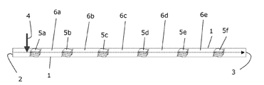
- FIG. 1 shows a schematic view of a feed system according to aspects of the invention in a horizontal or vertical linear configuration
- FIG. 2 shows a space-saving design of a feed system according to aspects of the invention in a loop arrangement
- FIG. 3 shows a feed system with a schematically illustrated irradiation unit
- FIG. 4 shows the curve of the feed efficiency of the ozone over the length of the feed system from FIG. 1 .
- FIG. 1 schematically shows a feed system for feeding gaseous ozone into the flow of contaminated water.
- the feed system is arranged in a pipe 1 between an inlet 2 and an outlet 3 .
- the pipe 1 is made from a material that is not attacked by oxidising agents (e.g. stainless steel or PVC).
- oxidising agents e.g. stainless steel or PVC.
- the installations located upstream of the inlet 2 and downstream of the outlet 3 are known from the prior art. These are the usual installations of a waterworks or of a water treatment plant.
- the feed system shown in FIG. 1 may be arranged in a horizontal and vertical orientation.
- the flow direction runs from left to right, that is to say from the inlet 2 to the outlet 3 .
- ozone feed point 4 which is configured as a nozzle lance, injection point or as a ceramic inlet element and is arranged in the main flow of the water.
- a first mixer 5 a is arranged downstream of the ozone feed point 4 .
- This is preferably a so-called static mixer which works without any movable components and brings the ozone, which is initially in gas form, into intimate contact with the flowing water solely on the basis of turbulence formation and thereby dissolves a portion of the gaseous ozone.
- the mixer 5 a is designed in such a way that the introduced ozone is not completely dissolved but rather initially only a proportion of approximately 20 to 30% is dissolved. Therefore 70 to 80% of the gaseous ozone remains undissolved in the main flow of the water to be treated in the pipe 1 .
- a first reaction zone 6 a is provided downstream of the first mixer 5 a .
- the water containing the partially dissolved ozone flows substantially undisturbed into this reaction zone for a time between 0.5 seconds and approximately 30 seconds, but preferably between 1 and 10 seconds, through the pipe 1 . It then reaches a downstream second mixer 5 b which once again dissolves approximately 20% of the gaseous ozone. Located downstream of the second mixer 5 b is a second reaction zone 6 b into which in turn approximately 50% of the gaseous ozone is transported with the main flow, while the dissolved ozone can react with the contaminations present in the water.
- the residence time in the second reaction zone 6 b is once again between 0.5 seconds and approximately 30 seconds, but preferably between 1 and 10 seconds.
- a third mixer 5 c which operates like the first mixer 5 a and the second mixer 5 b .
- the third mixer 5 c is followed by a third reaction zone 6 c then by a fourth mixer 5 d and a fourth reaction zone 6 d , a fifth mixer 5 e and a fifth reaction zone 6 e and a last, sixth mixer 5 f which is arranged immediately upstream of the outlet 3 .
- the mixers 5 a to 5 f and the reaction zones 6 a to 6 e are of identical design and size. Therefore, proceeding from the inlet 2 , the full quantity of ozone is firstly added in gas form at the ozone feed point 4 . As the main flow passes, the mixers 5 a to 5 f each mix the gaseous ozone into the main flow such that it partially dissolves. In the subsequent reaction zone 6 a to 6 e , the dissolved ozone can then react with the contaminations that can be oxidised.
- the mixing elements are made from a material that is not attacked by oxidising agents (e.g. stainless steel or PVC).
- oxidising agents e.g. stainless steel or PVC.
- the number of mixing elements can be adapted to the specific task, but the number should not be less than two mixing elements.
- the design and arrangement of the mixers and of the reaction zones means that the concentration of dissolved ozone increases only slightly from reaction zone to reaction zone. This gentle introduction of the ozone prevents local high concentrations of dissolved ozone and thus prevents the formation of bromate.
- another substance suitable for breaking down harmful substances may also be added to the main flow of the water to be treated, for example hydrogen peroxide.
- hydrogen peroxide a substance suitable for breaking down harmful substances
- the effect is that the ozone is still mostly in gas form after the first mixer and will not react with these substances.
- the hydrogen peroxide is introduced into the water flow not upstream of the ozone feed point but rather after the first reaction zone 6 a .
- the mixing of the hydrogen peroxide then takes place via the mixer 5 b .
- the advantage is obtained that substances which react directly with ozone have already been broken down in the first reaction zone 6 a .
- the reaction zone 6 a can be dimensioned such that all the substances which react directly with ozone are broken down before the mixer 5 b , and the quantity of dissolved ozone can no longer be detected. Substances which react with hydroxyl radicals will then be broken down in the subsequent reaction zones.
- the progress of the dissolved ozone concentration over time and the sequence of the reaction zones in which the ozone or the hydroxyl radicals react with the oxidisable substances contained in the water means that particularly low rates of production of undesired oxidation by-products, particularly of bromate, are achieved.
- more bromate is formed in systems in which ozone is already completely dissolved in a first, highly effective mixer.
- FIG. 2 Another exemplary embodiment of the present invention is illustrated in FIG. 2 .
- the pipe 1 is bent between the inlet 2 and the outlet 3 .
- the ozone feed device 4 is provided after the inlet. This is followed in the flow direction by the first mixer 5 a and the first reaction zone 6 a .
- a pipe elbow 7 deflects the main flow through 180° into the opposite direction. The main flow then enters the second mixer 5 b and the second reaction zone 6 b . These are followed once again by a pipe elbow 7 which deflects into a direction parallel to the original main flow.
- the third mixer 5 c and the third reaction zone 6 c follow. These are followed once again by a pipe elbow 7 which leads to the fourth mixer 5 d and the fourth reaction zone 6 d .
- a last pipe elbow 7 which leads to the fifth mixer 5 e and the fifth reaction zone 6 e .
- the latter finally opens into the outlet 3 .
- a so-called loop reactor is formed which is arranged in a much more compact manner.
- the loop reaction shown in FIG. 2 can be arranged horizontally or vertically.
- the portion of the pipe 1 in which the first mixer 5 a , the first reaction zone 6 a and the ozone feed point 4 are arranged may be oriented either with the main flow direction upwards, so that the gaseous ozone rises with the main flow direction due to the upward propulsion of the gas bubbles and is moved in co-current. If the first portion runs with the main flow direction downwards, the main flow direction entrains the ozone gas bubbles but the direction of propulsion is then counter to the main flow direction, so that the migration rate of the ozone bubbles is reduced and the residence time of the gaseous ozone in this region is increased.
- FIG. 3 shows another exemplary embodiment in which a first irradiation region 10 and a second irradiation region 11 are provided in addition to the oxidation described above.
- the irradiation regions 10 and 11 serve for introducing electromagnetic radiation into the main flow of the water to be treated, namely in the region between the mixers 5 b and 5 c , which represents the second reaction zone 6 b , and in the region between the mixer 5 d and the outlet 3 .
- This region represents the fourth reaction zone 6 d in this exemplary embodiment. It is also possible to install an irradiation region after the last reaction zone.
- a UV reactor as known for example from the disinfection of drinking water, may be installed in the pipe 1 in each of the regions 10 and 11 .
- a UV reactor comprises a stainless steel pipe which is installed in an existing pipeline by way of suitable flanges.
- One or more UV emitters are then arranged in the interior of the reactor, said emitters irradiating the flowing liquid with a defined dose of UV radiation.
- Mercury low-pressure emitters or mercury medium-pressure emitters are preferably used.
- UV radiation By combining the UV radiation with the oxidation process, it is possible that harmful substances which are known to be photo-sensitive (for example NDMA) can be eliminated in parallel with the ozone+H 2 O 2 combination.
- Hydroxyl radicals can be generated by irradiating dissolved ozone with UV rays. This results in the advantage that, in addition to the substances which react directly with ozone or which are deemed to be photo-sensitive, it is also possible to reduce substances which can only be reduced by hydroxyl radicals. Hydroxyl radicals can likewise be generated by irradiating dissolved hydrogen peroxide with UV rays.
- a measurement and adjustment system for controlling the system.
- This superordinate control system includes adjusting the required ozone quantity and the required quantity of hydrogen peroxide and measuring the concentrations of ozone in the gas phase and water phase as well as the concentration of hydrogen peroxide in the water phase.
- the required ozone quantity is adjusted by adapting the ozone concentration in the product gas and adapting the product gas flow.
- the required ozone quantity is calculated by defining the required ozone dose on the control unit and the volume flow of the water to be treated.
- the required quantity of hydrogen peroxide is likewise calculated by defining the hydrogen peroxide dose on the control unit and the volume flow of the water to be treated.
- the quantity of ozone dissolved in the water is determined by a suitable measuring device.
- the measurement may take place either directly after each mixer 5 a to 5 f and each reaction zone 6 a to 6 e or overall at the end of the mixing and reaction section. Determining the quantity of dissolved ozone has the advantage that, by virtue of this measurement, the required ozone quantity can be adapted to the actual ozone consumption. If the dissolved quantity of ozone should exceed a value to be defined, either the quantity of produced ozone can be reduced, the dose of hydrogen peroxide can be increased or the UV radiation can be increased or switched on. The measurement at the end of the mixing and reaction section serves to ensure that there is no longer any dissolved ozone in the process. If the value to be defined is exceeded, the required ozone quantity can also be required via the control unit.
- the hydrogen peroxide concentration can be determined after it has been mixed into the main flow and serves to check the actual hydrogen peroxide dose.
- the hydrogen peroxide concentration can also be determined at the end of the mixing and reaction section in order to be able to ascertain the efficiency of the process.
- the system can react autonomously to any change in the water quantity and in the composition of the water to be treated.
- an efficient process is provided in which only the quantities of ozone and hydrogen peroxide that are actually required are introduced.
- the operating costs can be reduced as a result.
- FIG. 4 shows, in a schematic diagram, how the ozone feed efficiency develops over the length l of the pipe 1 from FIG. 2 . Proceeding from the length 0, which coincides with the inlet 2 , the introduced quantity of ozone is initially 0. The introduction of the full quantity of gaseous ozone at the location of the feed point 4 is denoted by the measurement point 12 . Prior to reaching the first mixer 5 a , barely any ozone is transferred into the water phase.
- the value increases to approximately 35% because gaseous ozone dissolves in water over time even without the influence of mixing elements.
- the transferred ozone can react with the oxidisable substances contained in the water so that, prior to entering the second mixing element 5 b , most of the introduced ozone has reacted.
- the proportion of the ozone effectively introduced into the water rises to 55% and this increases to 60% in the subsequent reaction zone 6 b .
- the reaction zone 6 b again most of the introduced ozone reacts with the substances contained in the water.
- the proportion of transferred ozone rises to 75% and this increases to approximately 80% when passing the reaction zone 18 .
- the proportion of effectively introduced ozone is approximately 95%.
- the quantity of effectively introduced ozone reaches 100%. This means that, in the fifth mixer 5 e , the ozone added to the main flow as gaseous ozone at the ozone feed point 4 has been fully transferred into the main flow of the water and has reacted.
- the quantity of ozone available for the reaction with the oxidisable substances that are likewise dissolved in the water is only between 30 and 35% in the first reaction zone 6 a and hence there is no increased surplus of ozone.
- the formation of undesired substances such as bromate is in this way kept low.
- the ozone feed system using just one feed point 4 remains simple and does not require any complicated adjustment as is necessary for example when there are several feed points.
Abstract
A method for treating contaminated liquids in a flow by ozone, wherein the ozone is fed in gas form into the flow at one point and then is mixed into the flow in stages by mixers following one another in the flow direction, so that an absolute quantity of introduced ozone increases after each mixer until a feed efficiency of more than 95 percent is reached.
Description
This U.S. patent application is a divisional patent application of U.S. patent application Ser. No. 13/818,467, filed Feb. 22, 2013, which is a U.S. National Phase Patent Application of PCT International Patent Application Number PCT/EP2011/004210, filed Aug. 22, 2011, which claims priority benefit of German Patent No. DE 10 2010 035 519.4, filed Aug. 25, 2010, each of which is incorporated herein by reference in its entirety.
The present invention relates to a device for treating liquids by means of ozone, and to a method for treating liquids by means of ozone.
Increasingly high requirements are placed on the quality of drinking water and service water. Contaminations by organic substances are increasingly being recognised as harmful to health, thereby making removal necessary. On the other hand, such substances are more and more frequently reaching the groundwater and surface water. One example of this is the increasing concentration of pharmaceutical residues in surface water.
Such contaminations are reduced using various means. One of these means is the oxidation of organic contaminations. This is particularly effectively achieved in the so-called “Advanced Oxidation Process” (AOP), in which ozone and hydrogen peroxide are introduced into the contaminated water and then react with one another to form a hydroxyl radical. This hydroxyl radical is a highly effective oxidising agent.
From the document U.S. Pat. No. 5,578,205, which is incorporated by reference, it is known to add firstly hydrogen peroxide to a flow of contaminated water and then to add ozone downstream in a single step. In this way, impurities in the treated water are at least partially broken down. The document EP 0 561 458 A1, which is incorporated by reference, describes a method for treating contaminated water in which firstly oxygen and ozone are fed at high pressure into the water in a reaction container. Hydrogen peroxide can then be added later in a separate reaction container downstream of the ozone feed point. The document EP 1 021 377 B1, which is incorporated by reference, describes a method for treating contaminated water in which ozone and hydrogen peroxide are fed directly into the main water flow and both substances are then simultaneously fully dissolved and distributed in the water in a highly effective mixing device within a few seconds. This is intended to prevent the formation of bromate. Bromate is suspected of having a carcinogenic effect. There is therefore an upper limit for the permissible bromate content in drinking water. Said method is intended to minimise the formation of bromate in the event that bromide ions exist in the water to be treated.
The document U.S. Pat. No. 7,595,003 B2, which is incorporated by reference, describes a method for disinfecting ballast water on board ships by means of ozone. In order to avoid high bromate concentrations, the concentrations of bromide and bromate are monitored and the injection of ozone is controlled according thereto.
The present invention relates to further minimising the formation of bromate in water which contains bromide ions and which is treated with ozone.
Because the feed device feeds ozone into the water flow at one point, and because a plurality of mixers for mixing the ozone into the water are provided downstream of the feed point, wherein the mixers are arranged at a distance from one another so that a reaction zone forms between the mixers, the ozone is mixed into the water flow in stages so that the absolute quantity of the ozone introduced into the water increases with each mixing stage. This prevents the occurrence of excessively high local dissolved ozone concentrations which would lead to a formation of bromate.
It may be provided that the mixers are in each case static mixers without any movable parts.
The dimensioning of the feed device preferably provides that the distance between the mixers and the flow rate of the water are selected such that a volume of water takes between 0.5 seconds and approximately 30 seconds, but preferably between 1 and 10 seconds, between leaving one mixer and entering the next mixer.
In one preferred embodiment, the feed system is arranged in a pipe which comprises a plurality of straight sub-sections and U-shaped connecting pieces arranged therebetween. In connection with the description below, this mode of construction will be referred to as a “pipe that is bent in a loop-like manner” for the sake of simplicity.
For AOP processes, it may be provided that a feeding-in of hydrogen peroxide or other reagents is provided upstream of the ozone feed point.
Finally, the device may also be configured such that an irradiation with electromagnetic waves, in particular with UV radiation, is provided between two mixers or after the last mixer.
Examples of exemplary embodiments of the present invention will be described in more detail below with reference to the drawing, in which:
In FIG. 1 , the flow direction runs from left to right, that is to say from the inlet 2 to the outlet 3. Provided immediately adjacent to the inlet 2 is a schematically illustrated ozone feed point 4 which is configured as a nozzle lance, injection point or as a ceramic inlet element and is arranged in the main flow of the water.
A first mixer 5 a is arranged downstream of the ozone feed point 4. This is preferably a so-called static mixer which works without any movable components and brings the ozone, which is initially in gas form, into intimate contact with the flowing water solely on the basis of turbulence formation and thereby dissolves a portion of the gaseous ozone. The mixer 5 a is designed in such a way that the introduced ozone is not completely dissolved but rather initially only a proportion of approximately 20 to 30% is dissolved. Therefore 70 to 80% of the gaseous ozone remains undissolved in the main flow of the water to be treated in the pipe 1. A first reaction zone 6 a is provided downstream of the first mixer 5 a. The water containing the partially dissolved ozone flows substantially undisturbed into this reaction zone for a time between 0.5 seconds and approximately 30 seconds, but preferably between 1 and 10 seconds, through the pipe 1. It then reaches a downstream second mixer 5 b which once again dissolves approximately 20% of the gaseous ozone. Located downstream of the second mixer 5 b is a second reaction zone 6 b into which in turn approximately 50% of the gaseous ozone is transported with the main flow, while the dissolved ozone can react with the contaminations present in the water. The residence time in the second reaction zone 6 b is once again between 0.5 seconds and approximately 30 seconds, but preferably between 1 and 10 seconds. Provided downstream of the reaction zone 6 b is a third mixer 5 c, which operates like the first mixer 5 a and the second mixer 5 b. The third mixer 5 c is followed by a third reaction zone 6 c then by a fourth mixer 5 d and a fourth reaction zone 6 d, a fifth mixer 5 e and a fifth reaction zone 6 e and a last, sixth mixer 5 f which is arranged immediately upstream of the outlet 3.
In this exemplary embodiment, the mixers 5 a to 5 f and the reaction zones 6 a to 6 e are of identical design and size. Therefore, proceeding from the inlet 2, the full quantity of ozone is firstly added in gas form at the ozone feed point 4. As the main flow passes, the mixers 5 a to 5 f each mix the gaseous ozone into the main flow such that it partially dissolves. In the subsequent reaction zone 6 a to 6 e, the dissolved ozone can then react with the contaminations that can be oxidised.
In a known manner, the mixing elements are made from a material that is not attacked by oxidising agents (e.g. stainless steel or PVC). The number of mixing elements can be adapted to the specific task, but the number should not be less than two mixing elements.
The design and arrangement of the mixers and of the reaction zones means that the concentration of dissolved ozone increases only slightly from reaction zone to reaction zone. This gentle introduction of the ozone prevents local high concentrations of dissolved ozone and thus prevents the formation of bromate.
Upstream of the inlet 2, another substance suitable for breaking down harmful substances may also be added to the main flow of the water to be treated, for example hydrogen peroxide. Here, too, the effect is that the ozone is still mostly in gas form after the first mixer and will not react with these substances. In the case of adding hydrogen peroxide, this means that the full possible quantity of hydroxyl radicals is not formed immediately but rather the absolute quantity of hydroxyl radicals will increase upon passing through each further reaction zone.
It is also possible that the hydrogen peroxide is introduced into the water flow not upstream of the ozone feed point but rather after the first reaction zone 6 a. The mixing of the hydrogen peroxide then takes place via the mixer 5 b. By virtue of this mode of operation, the advantage is obtained that substances which react directly with ozone have already been broken down in the first reaction zone 6 a. This takes place on account of the high local ozone concentration occurring after the first mixer 5 a due to the partial mixing-in of gaseous ozone. The reaction zone 6 a can be dimensioned such that all the substances which react directly with ozone are broken down before the mixer 5 b, and the quantity of dissolved ozone can no longer be detected. Substances which react with hydroxyl radicals will then be broken down in the subsequent reaction zones.
The progress of the dissolved ozone concentration over time and the sequence of the reaction zones in which the ozone or the hydroxyl radicals react with the oxidisable substances contained in the water means that particularly low rates of production of undesired oxidation by-products, particularly of bromate, are achieved. In systems in which ozone is already completely dissolved in a first, highly effective mixer, more bromate is formed.
Another exemplary embodiment of the present invention is illustrated in FIG. 2 . Here, the pipe 1 is bent between the inlet 2 and the outlet 3. The ozone feed device 4 is provided after the inlet. This is followed in the flow direction by the first mixer 5 a and the first reaction zone 6 a. A pipe elbow 7 deflects the main flow through 180° into the opposite direction. The main flow then enters the second mixer 5 b and the second reaction zone 6 b. These are followed once again by a pipe elbow 7 which deflects into a direction parallel to the original main flow. The third mixer 5 c and the third reaction zone 6 c follow. These are followed once again by a pipe elbow 7 which leads to the fourth mixer 5 d and the fourth reaction zone 6 d. Finally provided is a last pipe elbow 7 which leads to the fifth mixer 5 e and the fifth reaction zone 6 e. The latter finally opens into the outlet 3. For the water treatment, approximately the same structure and the same mode of action are obtained as in the example of embodiment in FIG. 1 . Due to the bending, however, a so-called loop reactor is formed which is arranged in a much more compact manner. The loop reaction shown in FIG. 2 can be arranged horizontally or vertically. The portion of the pipe 1 in which the first mixer 5 a, the first reaction zone 6 a and the ozone feed point 4 are arranged may be oriented either with the main flow direction upwards, so that the gaseous ozone rises with the main flow direction due to the upward propulsion of the gas bubbles and is moved in co-current. If the first portion runs with the main flow direction downwards, the main flow direction entrains the ozone gas bubbles but the direction of propulsion is then counter to the main flow direction, so that the migration rate of the ozone bubbles is reduced and the residence time of the gaseous ozone in this region is increased.
A UV reactor, as known for example from the disinfection of drinking water, may be installed in the pipe 1 in each of the regions 10 and 11. Such a UV reactor comprises a stainless steel pipe which is installed in an existing pipeline by way of suitable flanges. One or more UV emitters are then arranged in the interior of the reactor, said emitters irradiating the flowing liquid with a defined dose of UV radiation. Mercury low-pressure emitters or mercury medium-pressure emitters are preferably used.
By combining the UV radiation with the oxidation process, it is possible that harmful substances which are known to be photo-sensitive (for example NDMA) can be eliminated in parallel with the ozone+H2O2 combination. Hydroxyl radicals can be generated by irradiating dissolved ozone with UV rays. This results in the advantage that, in addition to the substances which react directly with ozone or which are deemed to be photo-sensitive, it is also possible to reduce substances which can only be reduced by hydroxyl radicals. Hydroxyl radicals can likewise be generated by irradiating dissolved hydrogen peroxide with UV rays. This results in the advantage that, in addition to the substances which are deemed to be photo-sensitive, it is also possible to reduce substances which can only be reduced by hydroxyl radicals. However, this combination is valid only for low specific substance concentrations. It is also possible that the ozone stage, the hydrogen peroxide dosing and the UV irradiation are used in parallel in a process. Overall, by virtue of these arrangements, the advantage is obtained that it is possible during operation of the system to react to varying substances and substance concentrations by the different possible combinations. A more efficient process is provided as a result.
For the three examples of embodiments that have been described, a measurement and adjustment system is provided for controlling the system. This superordinate control system includes adjusting the required ozone quantity and the required quantity of hydrogen peroxide and measuring the concentrations of ozone in the gas phase and water phase as well as the concentration of hydrogen peroxide in the water phase. The required ozone quantity is adjusted by adapting the ozone concentration in the product gas and adapting the product gas flow. The required ozone quantity is calculated by defining the required ozone dose on the control unit and the volume flow of the water to be treated. The required quantity of hydrogen peroxide is likewise calculated by defining the hydrogen peroxide dose on the control unit and the volume flow of the water to be treated. By virtue of this manner of control, the required quantities of ozone and hydrogen peroxide can be adapted by the control unit of the system to the quantity of water to be treated.
The quantity of ozone dissolved in the water is determined by a suitable measuring device. The measurement may take place either directly after each mixer 5 a to 5 f and each reaction zone 6 a to 6 e or overall at the end of the mixing and reaction section. Determining the quantity of dissolved ozone has the advantage that, by virtue of this measurement, the required ozone quantity can be adapted to the actual ozone consumption. If the dissolved quantity of ozone should exceed a value to be defined, either the quantity of produced ozone can be reduced, the dose of hydrogen peroxide can be increased or the UV radiation can be increased or switched on. The measurement at the end of the mixing and reaction section serves to ensure that there is no longer any dissolved ozone in the process. If the value to be defined is exceeded, the required ozone quantity can also be required via the control unit.
The hydrogen peroxide concentration can be determined after it has been mixed into the main flow and serves to check the actual hydrogen peroxide dose. The hydrogen peroxide concentration can also be determined at the end of the mixing and reaction section in order to be able to ascertain the efficiency of the process.
By virtue of the control unit and the determination of the parameters mentioned above, the system can react autonomously to any change in the water quantity and in the composition of the water to be treated. As a result, an efficient process is provided in which only the quantities of ozone and hydrogen peroxide that are actually required are introduced. The operating costs can be reduced as a result.
It can be seen that the quantity of ozone available for the reaction with the oxidisable substances that are likewise dissolved in the water is only between 30 and 35% in the first reaction zone 6 a and hence there is no increased surplus of ozone. The formation of undesired substances such as bromate is in this way kept low. The ozone feed system using just one feed point 4 remains simple and does not require any complicated adjustment as is necessary for example when there are several feed points.
- 1. pipe
- 2. inlet
- 3. outlet
- 4. ozone feed point
- 5 a. mixing element
- 5 b. mixing element
- 5 c. mixing element
- 5 d. mixing element
- 5 e. mixing element
- 6 a. reaction zone
- 6 b. reaction zone
- 6 c. reaction zone
- 6 d. reaction zone
- 7. pipe elbow
- 8. outlet
- 10. irradiation region
- 11. irradiation region
- 12. measurement point
- 13. measurement point
- 14.
reaction zone 6 a - 15. measurement point
- 16.
reaction zone 6 b - 17. measurement point
- 18.
reaction zone 6 c - C. feed efficiency
- l. length
Claims (13)
1. A method for treating contaminated liquids in a flow by feeding a quantity of gaseous ozone into the flow at only one point and then gradually mixing the gaseous ozone into the flow in a plurality of mixing stages by means of mixers within each mixing stage without feeding more ozone into the flow, including controlling with a control unit the quantity of gaseous ozone added based upon a measured quantity of dissolved ozone at one or more locations downstream of one or more of the mixing stages, wherein the mixing stages follow one another in the flow direction and are separated by reaction zones, so that an absolute quantity of ozone cumulatively dissolved increases after each mixing stage until more than 95 percent of the quantity of gaseous ozone has cumulatively dissolved into the flow, while maintaining local dissolved ozone concentration in each reaction zone and mixing stage at or below a level that limits or prevents formation of undesired oxidation by-products from oxidizable substances contained in the liquid, wherein the local dissolved ozone concentration dissolved by a first mixing stage is in a range of 20% to 30% of the quantity of gaseous ozone, as controlled by the control unit.
2. The method according to claim 1 , wherein the flow is a water flow and ozone is fed into the water flow at just one point.
3. The method according to claim 1 , wherein a distance between the mixers and the flow rate of the liquid are selected such that a residence time for a volume of liquid in a reaction zone between leaving one mixer and entering the next mixer is between 0.5 seconds and 30 seconds.
4. The method according to claim 1 further comprising feeding-in hydrogen peroxide or other reagents into the liquid.
5. The method according to claim 4 , wherein the feeding-in takes place upstream of an ozone feed point.
6. The method according to claim 4 , wherein the feeding-in takes place downstream of an ozone feed point.
7. The method according to claim 6 , wherein the feeding-in takes place in a reaction zone.
8. The method according to claim 1 further comprising irradiation with electromagnetic waves between at least two mixers or after a last mixer.
9. The method according to claim 1 , wherein the contaminated liquid comprises water, the undesired oxidation by-products comprise bromates, and the oxidizable substances comprise bromide ions.
10. A method for treating contaminated liquids in a flow by feeding a quantity of gaseous ozone into the flow at only one point and then gradually mixing the gaseous ozone into the flow in a plurality of mixing stages by means of mixers within each mixing stage without feeding more ozone into the flow, including controlling with a control unit the quantity of gaseous ozone added based upon a measured quantity of dissolved ozone at one or more locations downstream of one or more of the mixing stages, wherein the mixing stages follow one another in the flow direction and are separated by reaction zones, so that an absolute quantity of ozone cumulatively dissolved increases after each mixing stage until more than 95 percent of the quantity of gaseous ozone has cumulatively dissolved into the flow, while maintaining local dissolved ozone concentration in each reaction zone and mixing stage at or below a level that limits or prevents formation of undesired oxidation by-products from oxidizable substances contained in the liquid, wherein the cumulative dissolved ozone concentration in a first reaction zone does not exceed 35% of the quantity of gaseous ozone, as controlled by the control unit.
11. The method according to claim 1 , wherein a majority of the local dissolved ozone at a beginning of each reaction zone is consumed by reaction in each reaction zone before a subsequent mixing stage, as controlled by the control unit.
12. The method according to claim 1 , comprising measuring the quantity of dissolved ozone after each mixing stage and after each reaction zone.
13. The method according to claim 1 , comprising measuring the quantity of dissolved ozone after the plurality of mixing stages and a final reaction section.
Priority Applications (1)
| Application Number | Priority Date | Filing Date | Title |
|---|---|---|---|
| US15/417,990 US10046994B2 (en) | 2010-08-25 | 2017-01-27 | Method for treating liquids with gaseous ozone |
Applications Claiming Priority (6)
| Application Number | Priority Date | Filing Date | Title |
|---|---|---|---|
| DE102010035519 | 2010-08-25 | ||
| DE102010035519.4 | 2010-08-25 | ||
| DE102010035519A DE102010035519B3 (en) | 2010-08-25 | 2010-08-25 | Apparatus and method for the treatment of liquids by means of ozone |
| PCT/EP2011/004210 WO2012025214A1 (en) | 2010-08-25 | 2011-08-22 | Device and method for treating liquids using ozone |
| US201313818467A | 2013-06-27 | 2013-06-27 | |
| US15/417,990 US10046994B2 (en) | 2010-08-25 | 2017-01-27 | Method for treating liquids with gaseous ozone |
Related Parent Applications (2)
| Application Number | Title | Priority Date | Filing Date |
|---|---|---|---|
| US13/818,467 Division US20130264292A1 (en) | 2010-08-25 | 2011-08-22 | Device and method for treating liquids by means of ozone |
| PCT/EP2011/004210 Division WO2012025214A1 (en) | 2010-08-25 | 2011-08-22 | Device and method for treating liquids using ozone |
Publications (2)
| Publication Number | Publication Date |
|---|---|
| US20170183247A1 US20170183247A1 (en) | 2017-06-29 |
| US10046994B2 true US10046994B2 (en) | 2018-08-14 |
Family
ID=44759638
Family Applications (2)
| Application Number | Title | Priority Date | Filing Date |
|---|---|---|---|
| US13/818,467 Abandoned US20130264292A1 (en) | 2010-08-25 | 2011-08-22 | Device and method for treating liquids by means of ozone |
| US15/417,990 Active US10046994B2 (en) | 2010-08-25 | 2017-01-27 | Method for treating liquids with gaseous ozone |
Family Applications Before (1)
| Application Number | Title | Priority Date | Filing Date |
|---|---|---|---|
| US13/818,467 Abandoned US20130264292A1 (en) | 2010-08-25 | 2011-08-22 | Device and method for treating liquids by means of ozone |
Country Status (9)
| Country | Link |
|---|---|
| US (2) | US20130264292A1 (en) |
| EP (1) | EP2609041B1 (en) |
| KR (1) | KR101912706B1 (en) |
| AU (1) | AU2011295383B2 (en) |
| CA (1) | CA2808944C (en) |
| DE (1) | DE102010035519B3 (en) |
| ES (1) | ES2544530T3 (en) |
| SG (1) | SG187910A1 (en) |
| WO (1) | WO2012025214A1 (en) |
Families Citing this family (5)
| Publication number | Priority date | Publication date | Assignee | Title |
|---|---|---|---|---|
| WO2015063581A1 (en) * | 2013-11-04 | 2015-05-07 | Intellectual Property Limited | Heavy metal and chemical destructor |
| FR3018206A1 (en) | 2014-03-07 | 2015-09-11 | Degremont | METHOD AND DEVICE FOR DISPERSION OF GAS IN A LIQUID |
| EP3202721A1 (en) | 2016-02-02 | 2017-08-09 | Eawag | Ozone-based advanced oxidation process |
| KR101894834B1 (en) * | 2016-08-24 | 2018-09-05 | 한국건설기술연구원 | Method for optimizing process control variable of advanced oxidation process (aop) using radical index determining apparatus with multi-channel continuous flow reactor |
| EP3378839A1 (en) * | 2017-03-23 | 2018-09-26 | Dunea N.V. | A water treatment system and a method of cleaning contaminated water |
Citations (15)
| Publication number | Priority date | Publication date | Assignee | Title |
|---|---|---|---|---|
| EP0561458A1 (en) | 1992-03-19 | 1993-09-22 | E.M. Engineering F.T.S. B.V. | Process and apparatus for the purification of water |
| US5578205A (en) | 1992-11-24 | 1996-11-26 | Trailigaz | Plant for removing micropollutants from untreated water by the combined action of ozone and hydrogen peroxide |
| US6024882A (en) | 1997-08-08 | 2000-02-15 | Applied Process Technology, Inc. | Process and apparatus for water decontamination |
| US6164813A (en) | 1999-02-05 | 2000-12-26 | Wang; Chiang-Ming | Static fluid mixing device with helically twisted elements |
| US6235207B1 (en) * | 1998-11-09 | 2001-05-22 | Fantom Technologies Inc. | Method for measuring the degree of treatment of a medium by a gas |
| EP1021377B1 (en) | 1997-08-08 | 2003-01-08 | Applied Process Technology, Inc. | Process and apparatus for water decontamination |
| US20030173276A1 (en) * | 2001-06-12 | 2003-09-18 | Hydrotreat, Inc. | Methods and apparatus for supplying high concentrations of dissolved oxygen and ozone for chemical and biological processes |
| US20040099608A1 (en) | 2002-11-18 | 2004-05-27 | Leffler Charles E. | Ballast water treatment system |
| US20060006122A1 (en) | 2004-07-07 | 2006-01-12 | Ivey Burns | Process control oxidation |
| US20060021951A1 (en) | 2002-04-17 | 2006-02-02 | Nutech O3 | Ozone retention method and system |
| KR100802889B1 (en) | 2007-02-27 | 2008-02-13 | 주식회사 엔케이 | Ballast water treatment system with ozone supply unit and reaction tank |
| US20080290045A1 (en) | 2007-04-19 | 2008-11-27 | Robinson B Keel | Process and apparatus for water decontamination |
| US7595003B2 (en) | 2003-07-18 | 2009-09-29 | Environmental Technologies, Inc. | On-board water treatment and management process and apparatus |
| CN101549900A (en) | 2008-04-01 | 2009-10-07 | 埃维昂矿泉水有限公司 | Process for producing bottled water sterilized by ozone and sterilized bottled water |
| US20100292844A1 (en) * | 2009-05-14 | 2010-11-18 | Omni Water Solutions Llc | Self-contained portable multi-mode water treatment system and methods |
Family Cites Families (3)
| Publication number | Priority date | Publication date | Assignee | Title |
|---|---|---|---|---|
| DE4319321A1 (en) * | 1993-05-17 | 1994-11-24 | Schmidding Wilh Gmbh & Co | Process for the treatment of bromide-containing water by ozone |
| US6602426B2 (en) * | 2001-10-01 | 2003-08-05 | Black & Veatch Holding Company | Water treatment using ozone and having a reduced likelihood of bromate formation from bromides found in the water |
| US7008543B2 (en) * | 2003-04-14 | 2006-03-07 | Contra Costa Water District | Use of chlorine dioxide and ozone for control of disinfection by-products in water supplies |
-
2010
- 2010-08-25 DE DE102010035519A patent/DE102010035519B3/en active Active
-
2011
- 2011-08-22 AU AU2011295383A patent/AU2011295383B2/en active Active
- 2011-08-22 CA CA2808944A patent/CA2808944C/en active Active
- 2011-08-22 SG SG2013012497A patent/SG187910A1/en unknown
- 2011-08-22 ES ES11764673.7T patent/ES2544530T3/en active Active
- 2011-08-22 WO PCT/EP2011/004210 patent/WO2012025214A1/en active Application Filing
- 2011-08-22 KR KR1020137007565A patent/KR101912706B1/en active IP Right Grant
- 2011-08-22 US US13/818,467 patent/US20130264292A1/en not_active Abandoned
- 2011-08-22 EP EP11764673.7A patent/EP2609041B1/en active Active
-
2017
- 2017-01-27 US US15/417,990 patent/US10046994B2/en active Active
Patent Citations (15)
| Publication number | Priority date | Publication date | Assignee | Title |
|---|---|---|---|---|
| EP0561458A1 (en) | 1992-03-19 | 1993-09-22 | E.M. Engineering F.T.S. B.V. | Process and apparatus for the purification of water |
| US5578205A (en) | 1992-11-24 | 1996-11-26 | Trailigaz | Plant for removing micropollutants from untreated water by the combined action of ozone and hydrogen peroxide |
| US6024882A (en) | 1997-08-08 | 2000-02-15 | Applied Process Technology, Inc. | Process and apparatus for water decontamination |
| EP1021377B1 (en) | 1997-08-08 | 2003-01-08 | Applied Process Technology, Inc. | Process and apparatus for water decontamination |
| US6235207B1 (en) * | 1998-11-09 | 2001-05-22 | Fantom Technologies Inc. | Method for measuring the degree of treatment of a medium by a gas |
| US6164813A (en) | 1999-02-05 | 2000-12-26 | Wang; Chiang-Ming | Static fluid mixing device with helically twisted elements |
| US20030173276A1 (en) * | 2001-06-12 | 2003-09-18 | Hydrotreat, Inc. | Methods and apparatus for supplying high concentrations of dissolved oxygen and ozone for chemical and biological processes |
| US20060021951A1 (en) | 2002-04-17 | 2006-02-02 | Nutech O3 | Ozone retention method and system |
| US20040099608A1 (en) | 2002-11-18 | 2004-05-27 | Leffler Charles E. | Ballast water treatment system |
| US7595003B2 (en) | 2003-07-18 | 2009-09-29 | Environmental Technologies, Inc. | On-board water treatment and management process and apparatus |
| US20060006122A1 (en) | 2004-07-07 | 2006-01-12 | Ivey Burns | Process control oxidation |
| KR100802889B1 (en) | 2007-02-27 | 2008-02-13 | 주식회사 엔케이 | Ballast water treatment system with ozone supply unit and reaction tank |
| US20080290045A1 (en) | 2007-04-19 | 2008-11-27 | Robinson B Keel | Process and apparatus for water decontamination |
| CN101549900A (en) | 2008-04-01 | 2009-10-07 | 埃维昂矿泉水有限公司 | Process for producing bottled water sterilized by ozone and sterilized bottled water |
| US20100292844A1 (en) * | 2009-05-14 | 2010-11-18 | Omni Water Solutions Llc | Self-contained portable multi-mode water treatment system and methods |
Non-Patent Citations (5)
| Title |
|---|
| Entire patent prosecution history of U.S. Appl. No. 13/818,467, filed Jun. 27, 2013, entitled, "Device and Method for Treating Liquids by Means of Ozone". |
| Final Office Action for U.S. Appl. No. 13/818,467, dated Jul. 28, 2016, 18 pages. |
| International Preliminary Report on Patentability dated Feb. 26, 2013, corresponding to International Application No. PCT/EP2011/004210, filed Aug. 22, 2011, 7 pages. |
| International Search Report dated Dec. 22, 2011, corresponding to International Application No. PCT/EP2011/004210, filed Aug. 22, 2011, 10 pages. |
| Non Final Office Action for U.S. Appl. No. 13/818,467, dated Jan. 29, 2016, 22 pages. |
Also Published As
| Publication number | Publication date |
|---|---|
| SG187910A1 (en) | 2013-03-28 |
| ES2544530T3 (en) | 2015-09-01 |
| WO2012025214A1 (en) | 2012-03-01 |
| AU2011295383A1 (en) | 2013-03-28 |
| EP2609041A1 (en) | 2013-07-03 |
| AU2011295383B2 (en) | 2014-09-25 |
| CA2808944C (en) | 2019-09-10 |
| KR101912706B1 (en) | 2018-10-30 |
| DE102010035519B3 (en) | 2011-12-08 |
| US20170183247A1 (en) | 2017-06-29 |
| EP2609041B1 (en) | 2015-05-27 |
| US20130264292A1 (en) | 2013-10-10 |
| KR20130099953A (en) | 2013-09-06 |
| CA2808944A1 (en) | 2012-03-01 |
Similar Documents
| Publication | Publication Date | Title |
|---|---|---|
| US10046994B2 (en) | Method for treating liquids with gaseous ozone | |
| JP3387597B2 (en) | Optimized reactor for ozonation in domestic water | |
| US6267878B1 (en) | Apparatus for the treatment of water by injection of ozone and carbon dioxide | |
| US6024882A (en) | Process and apparatus for water decontamination | |
| US20050152811A1 (en) | Apparatus and methods for efficient generation of chlorine dioxide | |
| EP2527301A1 (en) | Method and arrangement for a water treatment | |
| CN102378736B (en) | The method and apparatus of preparation molecular bromine | |
| JP2021535998A (en) | Systems and methods for measuring water composition | |
| EP1021377B1 (en) | Process and apparatus for water decontamination | |
| US20100147776A1 (en) | Magnesium thiosulfate as chlorine quencher and scrubber | |
| WO2020116655A1 (en) | Water treatment control device, water treatment system, and water treatment device | |
| JP2007185610A (en) | Device for controlling injection of flocculant | |
| Chiang et al. | Modeling an ozone bubble column for predicting its disinfection efficiency and control of DBP formation | |
| WO2017175794A1 (en) | Accelerated oxidation treatment method and accelerated oxidation treatment device | |
| JP2005161142A (en) | Apparatus for producing sterilizing water continuously | |
| Kask et al. | Oxidation of aqueous N-nitrosodiethylamine: Experimental comparison of pulsed corona discharge with H2O2-assisted ozonation | |
| JP4829195B2 (en) | Ozone injection control method and water treatment apparatus | |
| KR101674984B1 (en) | Apparatus for controlling ozone and method for controlling ozone | |
| JP6749463B2 (en) | Accelerated oxidation treatment method and accelerated oxidation treatment device | |
| JP2005324121A (en) | Water treatment method and water treatment apparatus | |
| EP3378839A1 (en) | A water treatment system and a method of cleaning contaminated water | |
| Cao et al. | Insights into the formation of halonitromethanes from dimethylamine involving bromide ion during UV/chloramine disinfection | |
| Sutton et al. | THM control in wastewater effluent with chlorine dioxide as a supplementary oxidant | |
| JP2018051492A (en) | Device for treating waste water containing ammonia | |
| JP2006068599A (en) | Ammonia nitrogen-containing waste water treatment apparatus |
Legal Events
| Date | Code | Title | Description |
|---|---|---|---|
| AS | Assignment |
Owner name: XYLEM IP HOLDINGS LLC, NEW YORK Free format text: ASSIGNMENT OF ASSIGNORS INTEREST;ASSIGNORS:WIELAND, ARNE;KAMPMANN, MARTIN;SCHEIDELER, JENS;AND OTHERS;SIGNING DATES FROM 20130324 TO 20130403;REEL/FRAME:041278/0675 |
|
| STCF | Information on status: patent grant |
Free format text: PATENTED CASE |
|
| MAFP | Maintenance fee payment |
Free format text: PAYMENT OF MAINTENANCE FEE, 4TH YEAR, LARGE ENTITY (ORIGINAL EVENT CODE: M1551); ENTITY STATUS OF PATENT OWNER: LARGE ENTITY Year of fee payment: 4 |