US10035657B2 - Method and device for conveying piece goods from a stack or pile - Google Patents
Method and device for conveying piece goods from a stack or pile Download PDFInfo
- Publication number
- US10035657B2 US10035657B2 US15/279,712 US201615279712A US10035657B2 US 10035657 B2 US10035657 B2 US 10035657B2 US 201615279712 A US201615279712 A US 201615279712A US 10035657 B2 US10035657 B2 US 10035657B2
- Authority
- US
- United States
- Prior art keywords
- finger unit
- belt
- piece goods
- stack
- pile
- Prior art date
- Legal status (The legal status is an assumption and is not a legal conclusion. Google has not performed a legal analysis and makes no representation as to the accuracy of the status listed.)
- Active
Links
Images




Classifications
-
- B—PERFORMING OPERATIONS; TRANSPORTING
- B65—CONVEYING; PACKING; STORING; HANDLING THIN OR FILAMENTARY MATERIAL
- B65G—TRANSPORT OR STORAGE DEVICES, e.g. CONVEYORS FOR LOADING OR TIPPING, SHOP CONVEYOR SYSTEMS OR PNEUMATIC TUBE CONVEYORS
- B65G21/00—Supporting or protective framework or housings for endless load-carriers or traction elements of belt or chain conveyors
- B65G21/10—Supporting or protective framework or housings for endless load-carriers or traction elements of belt or chain conveyors movable, or having interchangeable or relatively movable parts; Devices for moving framework or parts thereof
-
- B—PERFORMING OPERATIONS; TRANSPORTING
- B65—CONVEYING; PACKING; STORING; HANDLING THIN OR FILAMENTARY MATERIAL
- B65G—TRANSPORT OR STORAGE DEVICES, e.g. CONVEYORS FOR LOADING OR TIPPING, SHOP CONVEYOR SYSTEMS OR PNEUMATIC TUBE CONVEYORS
- B65G15/00—Conveyors having endless load-conveying surfaces, i.e. belts and like continuous members, to which tractive effort is transmitted by means other than endless driving elements of similar configuration
-
- B—PERFORMING OPERATIONS; TRANSPORTING
- B65—CONVEYING; PACKING; STORING; HANDLING THIN OR FILAMENTARY MATERIAL
- B65G—TRANSPORT OR STORAGE DEVICES, e.g. CONVEYORS FOR LOADING OR TIPPING, SHOP CONVEYOR SYSTEMS OR PNEUMATIC TUBE CONVEYORS
- B65G21/00—Supporting or protective framework or housings for endless load-carriers or traction elements of belt or chain conveyors
- B65G21/10—Supporting or protective framework or housings for endless load-carriers or traction elements of belt or chain conveyors movable, or having interchangeable or relatively movable parts; Devices for moving framework or parts thereof
- B65G21/12—Supporting or protective framework or housings for endless load-carriers or traction elements of belt or chain conveyors movable, or having interchangeable or relatively movable parts; Devices for moving framework or parts thereof to allow adjustment of position of load-carrier or traction element as a whole
-
- B—PERFORMING OPERATIONS; TRANSPORTING
- B65—CONVEYING; PACKING; STORING; HANDLING THIN OR FILAMENTARY MATERIAL
- B65G—TRANSPORT OR STORAGE DEVICES, e.g. CONVEYORS FOR LOADING OR TIPPING, SHOP CONVEYOR SYSTEMS OR PNEUMATIC TUBE CONVEYORS
- B65G21/00—Supporting or protective framework or housings for endless load-carriers or traction elements of belt or chain conveyors
- B65G21/10—Supporting or protective framework or housings for endless load-carriers or traction elements of belt or chain conveyors movable, or having interchangeable or relatively movable parts; Devices for moving framework or parts thereof
- B65G21/14—Supporting or protective framework or housings for endless load-carriers or traction elements of belt or chain conveyors movable, or having interchangeable or relatively movable parts; Devices for moving framework or parts thereof to allow adjustment of length or configuration of load-carrier or traction element
-
- B—PERFORMING OPERATIONS; TRANSPORTING
- B65—CONVEYING; PACKING; STORING; HANDLING THIN OR FILAMENTARY MATERIAL
- B65G—TRANSPORT OR STORAGE DEVICES, e.g. CONVEYORS FOR LOADING OR TIPPING, SHOP CONVEYOR SYSTEMS OR PNEUMATIC TUBE CONVEYORS
- B65G47/00—Article or material-handling devices associated with conveyors; Methods employing such devices
- B65G47/02—Devices for feeding articles or materials to conveyors
- B65G47/04—Devices for feeding articles or materials to conveyors for feeding articles
- B65G47/06—Devices for feeding articles or materials to conveyors for feeding articles from a single group of articles arranged in orderly pattern, e.g. workpieces in magazines
-
- B—PERFORMING OPERATIONS; TRANSPORTING
- B65—CONVEYING; PACKING; STORING; HANDLING THIN OR FILAMENTARY MATERIAL
- B65G—TRANSPORT OR STORAGE DEVICES, e.g. CONVEYORS FOR LOADING OR TIPPING, SHOP CONVEYOR SYSTEMS OR PNEUMATIC TUBE CONVEYORS
- B65G59/00—De-stacking of articles
- B65G59/02—De-stacking from the top of the stack
-
- B—PERFORMING OPERATIONS; TRANSPORTING
- B65—CONVEYING; PACKING; STORING; HANDLING THIN OR FILAMENTARY MATERIAL
- B65G—TRANSPORT OR STORAGE DEVICES, e.g. CONVEYORS FOR LOADING OR TIPPING, SHOP CONVEYOR SYSTEMS OR PNEUMATIC TUBE CONVEYORS
- B65G61/00—Use of pick-up or transfer devices or of manipulators for stacking or de-stacking articles not otherwise provided for
-
- B—PERFORMING OPERATIONS; TRANSPORTING
- B65—CONVEYING; PACKING; STORING; HANDLING THIN OR FILAMENTARY MATERIAL
- B65G—TRANSPORT OR STORAGE DEVICES, e.g. CONVEYORS FOR LOADING OR TIPPING, SHOP CONVEYOR SYSTEMS OR PNEUMATIC TUBE CONVEYORS
- B65G67/00—Loading or unloading vehicles
- B65G67/02—Loading or unloading land vehicles
- B65G67/04—Loading land vehicles
- B65G67/08—Loading land vehicles using endless conveyors
-
- B—PERFORMING OPERATIONS; TRANSPORTING
- B65—CONVEYING; PACKING; STORING; HANDLING THIN OR FILAMENTARY MATERIAL
- B65G—TRANSPORT OR STORAGE DEVICES, e.g. CONVEYORS FOR LOADING OR TIPPING, SHOP CONVEYOR SYSTEMS OR PNEUMATIC TUBE CONVEYORS
- B65G67/00—Loading or unloading vehicles
- B65G67/02—Loading or unloading land vehicles
- B65G67/24—Unloading land vehicles
-
- B—PERFORMING OPERATIONS; TRANSPORTING
- B65—CONVEYING; PACKING; STORING; HANDLING THIN OR FILAMENTARY MATERIAL
- B65G—TRANSPORT OR STORAGE DEVICES, e.g. CONVEYORS FOR LOADING OR TIPPING, SHOP CONVEYOR SYSTEMS OR PNEUMATIC TUBE CONVEYORS
- B65G2207/00—Indexing codes relating to constructional details, configuration and additional features of a handling device, e.g. Conveyors
- B65G2207/08—Adjustable and/or adaptable to the article size
Definitions
- the invention relates to a method for conveying piece goods, in particular packages, from a stack and/or pile of piece goods.
- the invention also relates to a belt-type conveyor device, preferably a telescopic belt-type conveyor, for conveying piece goods, in particular packages, having a conveyor belt which circulates around a supporting structure.
- Piece goods in particular packages, and belt-type conveyor devices used for this purpose are already known. These are used for example in order to unload stacked or piled-up piece goods from a loading space, in particular of a heavy goods vehicle, semitrailer, trailer, container, transport container, interchangeable container and/or rolling container.
- the piece goods which may be packages, are in this case firstly brought down from the stack or pile and thereafter transported onward, for example in order to be supplied for sorting, temporary storage or other processing.
- the present invention is based on the object of configuring and further developing the methods and the belt-type conveyor device in each case of the type mentioned in the introduction and described in more detail above such that satisfactory handling of piece goods can be realized.
- Said object is achieved according to embodiments of the method disclosed herein for conveying piece goods, in particular packages, from a stack and/or pile of piece goods, using a finger unit comprising at least two flexible flank elements which extend jointly from one end of the finger unit to an opposite end of the finger unit, wherein the at least two flexible flank elements are, between the two ends of the finger unit, in each case flexibly connected to one another by way of a multiplicity of webs such that the finger unit is adjustable at least from a curved position into a straightened position and back,
- a belt-type conveyor device preferably telescopic belt-type conveyor
- the supporting structure has at least one finger unit which supports the conveyor belt at least in an operating situation
- the finger unit has at least two flexible flank elements which extend jointly from one end of the finger unit to an opposite end of the finger unit, wherein the at least two flexible flank elements are, between the two ends of the finger unit, in each case flexibly connected to one another by way of a multiplicity of webs, such that the finger unit is adjustable from a curved position into a straightened position and back, wherein the finger unit is provided at a free end of the belt-type conveyor, and wherein at least that end of the at least one finger unit which is assigned to the free end of the belt-type conveyor has a def
- the above-stated object is achieved, in the case of embodiments of a belt-type conveyor device disclosed herein, in that the supporting structure has at least one finger unit which supports the conveyor belt at least in an operating situation, in that the finger unit has at least two flexible flank elements which extend jointly from one end of the finger unit to an opposite end of the finger unit, and in that the at least two flexible flank elements are, between the two ends of the finger unit, in each case flexibly connected to one another by way of a multiplicity of webs, such that the finger unit is adjustable at least from a curved position into a straightened position and back.
- a stack is to be understood to mean a multiplicity of piece goods arranged one on top of the other and adjacent to one another in an at least substantially regular pattern
- a pile is to be understood to mean an at least substantially unorganized accumulation of piece goods provided on top of and adjacent to one another. It may be the case that an accumulation of piece goods has both stack-like sections and pile-like sections, as a result of which the accumulation can be of both partially stack-like and partially pile-like form.
- the so-called fin-ray effect can be observed in the tailfins of bony fish. If one presses one's finger against the side thereof, the fins curve not away but bend partially toward the finger. This is possible by way of a special construction of the fins. This is reproduced in the case of the finger unit of the invention.
- the finger unit has at least two flexible flank elements which extend jointly from one end of the finger unit to an opposite end of the finger unit.
- the flexibility may for example be provided by way of elastic flank elements or by way of a link chain composed of rigid chain links which are connected pivotably or articulatedly to one another.
- corresponding flexibility is required only in one space direction. Flexibility is not imperatively required in the space directions perpendicular thereto.
- flank elements can also easily be provided, for example, in strip-like form.
- a bar-like design of the flank elements is however alternatively also possible.
- the corresponding flexibility of the flank elements ultimately permits a curvature of the finger unit from a straightened position into a curved position, for example similarly to the curvature of a finger.
- the at least two flank elements are, between the two ends of the finger unit, in each case flexibly connected to one another by way of a multiplicity of webs.
- the webs may be of rigid form and may be pivotably or articulatedly connected to the flank elements. It is however optionally also possible for flexible, in particular elastic webs to be used as an alternative to pivotable or articulated connections to the at least two flank elements. In this way, it is achieved that the webs can pivot relative to the at least two flank elements in order to thereby permit a curvature of the finger unit from a straightened position into a curved position and back.
- a straightened position of the finger unit can be understood to mean a maximally straightened and/or elongate orientation of the finger unit. It may however also be a position from which the finger unit can, by way of further curvature, be adjusted into a position which is more curved than the straightened position. Accordingly, the curved position also need not be a maximally curved position.
- the expressions “straightened position” and “curved position” can thus optionally be understood merely in relative terms, that is to say as relative positions with respect to one another. Furthermore, it should be taken into consideration that the finger unit can be adjusted from a straightened position into different curved positions in opposite directions.
- the finger unit ultimately permits an adaptation of the shape to the shape of the piece goods to be transported when the finger unit presses against the piece goods or vice versa.
- it is firstly possible to provide a relatively large contact surface of finger unit and item of piece goods, which improves the handling of the item of piece goods.
- the contact pressure between finger unit and item of piece goods can be lowered, which promotes damage-free handling of piece goods.
- the construction of the finger unit however also optionally permits the setting of a prior curvature without the presence of contact between the finger unit and the at least one item of piece goods.
- the flank elements it is for example possible for the flank elements to be adjusted relative to one another in the longitudinal direction of the finger unit.
- the finger unit then curves away from the flank element, which is adjusted further, in relation to the at least one further flank element, in the longitudinal direction toward the opposite end of the finger unit.
- the finger unit may for example also have three or more flank elements which are connected to one another by way of webs.
- the webs may for example be of cross-shaped, star-shaped, rectangular, square, oval or circular form in order that they can be easily fixed to all flank elements.
- the corresponding connections are in this case preferably of either pivotable or rotatable form, and/or the webs are of flexible form.
- Packages are to be understood to mean a particular type of piece goods.
- Packages are goods packaged in packagings.
- Packages may therefore have at least one outer packaging and may be provided for example as packets, boxes or containers.
- the above-described finger unit may be utilized for bringing piece goods, in particular packages, down from a stack and/or pile of piece goods.
- the at least one finger unit is pressed against the stack and/or pile of piece goods, in particular against at least one item of piece goods situated on the top of the stack and/or pile.
- the finger unit is at least partially moved in a direction which can be referred to as gripping direction.
- the at least one item of piece goods then presses against the finger unit, in particular against at least one flank element.
- the pressure on the finger unit is in this case so great that the finger unit, in particular the at least one flank element, is locally impressed.
- the at least one flank element is moved in sections against struts and/or in the direction of at least one further flank element.
- at least one flank element is adjusted from a straightened position into a curved position. This means for example that a part of the corresponding flank element is bent in the direction of the at least one item of piece goods.
- the at least one item of piece goods is thus at least partially gripped by the finger unit, in particular by at least one flank element, as a result of the impressing of the finger unit. Said gripping action can now, as required, effect a form fit between the finger element and the at least one item of piece goods in at least one direction.
- the at least one at least partially gripped item of piece goods can be moved by the finger unit in a transport direction which has at least one movement component perpendicular to the gripping direction. In this way, the at least one item of piece goods is moved from the stack and/or pile.
- the gripping direction is in this case, for the sake of simplicity, preferably oriented at least substantially vertically, whereas the transport direction is oriented at least substantially horizontally.
- the auto-adaptive characteristic of the finger unit which has the effect that piece goods of very different shape are at least partially gripped, it is always possible for a very large contact area between the finger unit and the piece goods to be realized, such that the area-specific pressing pressure, or the contact pressure, can be kept low in order that the piece goods are not damaged during the handling process.
- a form fit can be realized in at least a direction which facilitates the conveying of the piece goods from the stack and/or from the pile. In both cases, there is in each case no need for targeted adaptation to the piece goods to be conveyed.
- the corresponding handling of the piece goods is made, for example, more reliable, less damaging and more precise.
- the above-described method steps are performed multiple times or even a multiplicity of times in succession, whereby the stack and/or the pile can be gradually cleared away for example by repeated removal of piece goods.
- the finger unit is for example pressed again against at least one further item of piece goods of the stack and/or pile, whereby the at least one further item of piece goods is at least partially gripped by the finger element.
- the at least one further item of piece goods is also moved in the transport direction from the stack and/or pile by the finger unit. It is thus possible for the stack and/or pile to be, at least for the most part, cleared away by way of a similar sequence of similar method steps.
- the at least one item of piece goods gripped by the finger unit may be removed in the transport direction from the stack and/or pile at least partially by way of a movement of the finger unit. This is expedient in particular if a form fit exists between the finger unit and the at least one gripped item of piece goods in the transport direction. The handling of the piece goods is thus possible in a simple and reliable manner.
- the removal of the at least one item of piece goods from the stack and/or pile may also be at least partially based on some other principle.
- the at least one at least partially gripped item of piece goods may be moved in the transport direction from the stack and/or pile at least partially by way of a movement of a conveyor belt which is provided between the finger unit and the at least one partially gripped item of piece goods.
- the pressing of the finger unit against the at least one item of piece goods of the stack and/or pile of piece goods causes frictional engagement to be generated.
- a large connecting area is provided between the conveyor belt, which extends at least partially along the finger element or even circulates around the finger element, and the at least one item of piece goods.
- Both of these promote the transport of the at least one item of piece goods by way of a movement, in the transport direction, of the conveyor belt between the finger device and the at least one item of piece goods.
- the transport of piece goods by way of a conveyor belt is easy to realize in terms of construction, and is reliable.
- At least one belt-type conveyor device is used for the removal of the at least one item of piece goods.
- Said belt-type conveyor device may then comprise the at least one finger unit and the conveyor belt which runs at least partially along the finger unit.
- the at least one at least partially gripped item of piece goods may also be moved in the transport direction from the stack and/or pile at least partially by way of a movement of some other transport means provided between the finger unit and the at least one partially gripped item of piece goods.
- transport means use is made in particular of rollers which can be driven by way of a corresponding drive.
- rigid and stable small hairs, for example on the at least one flank element to be provided which are adjustable in terms of their orientation relative to the flank element, for example by way of a piezo effect.
- the at least one finger unit may provide not only for auto-adaptive partial gripping of piece goods but also for an automatic release of the piece goods after the movement of the piece goods from the stack and/or pile.
- the at least one item of piece goods at least partially gripped by the finger unit can, after the movement from the stack and/or pile, be released from the finger unit in the direction of gravitational force by way of an adjustment of the finger unit from a curved position into a straightened position.
- the finger unit can be adjusted from a curved position into a less curved or straightened position and can release the at least one item of piece goods.
- the finger unit is no longer partially impressed by the item of piece goods. Without partial impressing of the finger unit, the finger unit no longer curves, or at any rate curves less in the direction of the item of piece goods, which is consequently released.
- the finger unit firstly, that is to say before the finger unit presses in particular from above against the stack and/or pile of piece goods, is moved over at least parts of the stack and/or pile of piece goods. Then, at least one item of piece goods lying on top of the stack and/or the pile can be placed in contact with the finger device.
- the finger unit before making contact with at least one item of piece goods, is moved over the stack and/or pile in an approach direction at least partially opposed to the transport direction.
- the finger device can be moved in the approach direction over a large distance, it is possible for even very wide or very deep stacks and/or piles to be cleared away. This is advantageous in particular during the unloading of piece goods from a heavy goods vehicle, trailer, semitrailer and/or container, because these often have a very long loading space.
- the handling of the piece goods can be improved if a belt-type conveyor device is positioned laterally adjacent to the stack and/or pile. This may be realized such that the at least one item of piece goods moved in the transport direction from the stack and/or pile by the finger unit falls, slides and/or is moved on to a conveyor belt of the belt-type conveyor device. The at least one item of piece goods is thus collected by the belt-type conveyor device and transported away from the stack and/or pile on the conveyor belt of the belt-type conveyor device. In this way, the clearing-away of a stack and/or pile of piece goods can be carried out easily, quickly and reliably.
- a belt-type device to be positioned laterally adjacent to the stack and/or the pile, use is made of a telescopic belt-type conveyor and/or a belt-type conveyor device according to the embodiments disclosed herein.
- the belt-type conveyor device can be easily readjusted as the stack and/or pile of piece goods is gradually cleared away.
- the expression “laterally” may also be understood to mean in front of the stack and/or the pile as viewed from the belt-type conveyor device. If a belt-type conveyor device according to the embodiments disclosed herein, it is again possible to utilize the auto-adaptive characteristic of the finger unit.
- the shape of the finger unit adapts as required to the shape of the item of piece goods, which can increase the contact area on the conveyor belt and improve the transportation along the belt-type conveyor device.
- the finger of the belt-type conveyor device may however also have a prior curvature, for example in order to reduce the falling height of the piece goods and/or in order to permit an adaptation of the belt-type conveyor device to the height of the stack and/or pile which decreases as the stack and/or pile is cleared away.
- the belt-type conveyor device In order that the piece goods removed from the stack and/or pile can be received without being damaged and in a reliable manner, it is possible for the belt-type conveyor device to be adjusted progressively further downward with decreasing height of that region of the stack and/or pile which is adjacent to the belt-type conveyor device. This need not be performed in continuous fashion, but rather may also be performed in stepped fashion. For example, it is initially the case that the belt-type conveyor device is positioned high enough that the piece goods do not fall too far before they are collected by the belt-type conveyor device. At a later point in time, the belt-type conveyor device is set low enough that the piece goods can still be moved downward from the remaining stack and/or pile onto the belt-type conveyor device without problems.
- the position and/or the contour of the stack and/or pile of packages is at least partially captured by at least one sensor. It is thus possible for the finger unit to be moved in targeted fashion to the piece goods situated on the stack and/or pile in order to remove said piece goods from the stack and/or pile.
- the capturing of the stack and/or pile is possible easily and in a precise manner if an optical sensor, in particular a camera, is used.
- the movement of the finger unit can then be controlled at least partially in a manner dependent on the position and/or contour of the stack and/or pile of piece goods as captured by the sensor. It is accordingly possible for piece goods to be removed without problems from stacks and/or piles of different form, without specific manual adaptation of the method having to be performed in each case. This increases the flexibility and efficiency of the method.
- triangulation is a geometric method of optical distance measurement by way of precise angle measurement within triangles. The calculation is performed by way of trigonometric functions.
- the triangulation furthermore requires at least two sensors for precise distance measurement and direction finding of individual points of the stack and/or pile proceeding from the sensors.
- a finger unit having at least one pressure sensor, preferably on at least one flank element.
- the pressure sensor then transmits, for example, the measured pressure to a control unit, which thereupon controls the finger unit such that a predefined maximum pressure is not exceeded.
- a control unit which thereupon controls the finger unit such that a predefined maximum pressure is not exceeded.
- the finger unit it is however also possible, by way of the at least one pressure sensor, for the finger unit to be controlled such that an adequate pressure is applied to the at least one item of piece goods by the finger unit in order to be able to safely and reliably remove the at least one item of piece goods from the stack and/or pile.
- the method is not restricted to the use of a finger unit. It is rather possible for multiple finger units to be used simultaneously and/or in succession. To simplify the method, and in order to make it possible for even large, in particular wide stacks and/or piles of piece goods to be cleared away, use may be made of a multiplicity of finger elements.
- the finger units may then, over the width of the stack and/or pile, at least partially grip different piece goods and move them from the stack and/or pile. In this way, it is for example possible for heavy goods vehicles, trailers, semitrailers and containers to be unloaded quickly.
- the finger elements prefferably be combined to form a common hand unit. It is thus possible, by way of the movement of the hand unit, for the finger units to be moved jointly, which reduces the control outlay. Alternatively or in addition, it is furthermore expedient for the multiplicity of finger elements to be moved simultaneously, and parallel to one another, in the approach direction, gripping direction and/or transport direction. This simplifies the execution of the method and the control of the fingers. This is all the more applicable the more said movements are performed jointly.
- the multiplicity of fingers is distributed substantially over the entire width of the stack and/or pile and/or over the entire width of a loading space which has the stack and/or pile, in particular of a heavy goods vehicle, semitrailer, trailer, container, transport container, interchangeable container and/or rolling container. This offers the advantage that the stack and/or pile can be cleared away over its entire width simultaneously.
- the piece goods lying on the stack and/or pile are moved from the stack and/or pile onto the conveyor belt of the belt-type conveyor device by way of a method according to the embodiments disclosed herein.
- the auto-adaptive characteristic of the finger unit is utilized both during the transporting of the piece goods from the stack and/or pile onto the belt-type conveyor device and during the collecting and transporting of the piece goods by the belt-type conveyor device.
- a belt-type conveyor device according to one of the embodiments disclosed herein is expedient, whether it be for transporting the piece goods from the stack and/or the pile onto the belt-type conveyor device provided laterally adjacent to the stack and/or pile, or actually as the belt-type conveyor device positioned laterally adjacent to the stack and/or pile of piece goods.
- the advantages discussed in conjunction with the embodiments disclosed herein are basically attained, to which reference is made at this juncture for the sake of avoiding unnecessary repetition and for improved comprehensibility.
- the free end of the belt-type conveyor device is adjusted progressively downward with decreasing height of that region of the stack and/or pile which is adjacent to the belt-type conveyor device, it can be achieved that the piece goods initially do not fall too far from the stack and/or pile onto the belt-type conveyor device, in order that damage to the piece goods is prevented. Furthermore, however, it can also be achieved that piece goods pass downward onto the belt-type conveyor device without problems even when the stack adjacent to the belt-type conveyor device has already been largely cleared away.
- continuous adjustment of the belt-type conveyor device is not necessary. Rather, a stepped adjustment of the belt-type conveyor device is adequate.
- the belt-type conveyor device can be adjusted particularly easily and precisely by virtue of the finger unit being adjusted by way of a drive unit.
- the at least two flank elements can be adjusted relative to one another in a longitudinal direction of the finger unit. This then has the effect that the finger unit of the belt-type conveyor device is adjusted between at least one curved position and one straightened position and back again as required.
- the finger unit is set to be flexible enough, it is possible for at least one item of piece goods conveyed by the conveyor belt to locally impress the finger unit, in particular at least one flank element, such that the finger unit, in particular the at least one flank unit, is, adjacent to the item of piece goods, deflected upward, in particular in the direction of the item of piece goods. In this way, partial gripping of the item of piece goods can be realized. It is thus basically possible for the contact area of the item of piece goods on the conveyor belt to be enlarged. Alternatively or in addition, it is also possible for more reliable conveyance of the item of piece goods on the conveyor belt to be achieved.
- the flexibility of the finger device can basically be reduced by way of a reduction of the number of webs in relation to the longitudinal extent of the finger element.
- the at least two flank elements and the multiplicity of webs are connected to one another and designed such that an impressing of at least one flank element in an impressing direction oblique, in particular perpendicular, to the longitudinal extent of the flank element results in a deflection of the flank element, outside the impressed region, in a direction opposite to the impressing direction.
- This behavior of the finger unit which can be achieved and set by way of the orientation of the flank elements relative to one another and the orientation of the webs relative to the flank elements, permits an auto-adaptive adjustment of the finger element to the shape of the piece goods and thus an adaptation of the belt-type conveyor device even to very different piece goods.
- the contact area between the conveyor belt and the item of piece goods is enlarged, and the piece is held and supported more reliably by the conveyor belt. This ultimately results in substantially disruption-free operation of the belt-type conveyor device.
- the adjustment of the flank elements from the at least one straightened position into the at least one curved position is expedient in particular for the adjustment of the flank elements from the at least one straightened position into the at least one curved position to be performed counter to a restoring force, in particular of the flank elements.
- the deformation of the finger unit can be influenced in a desired manner. The lower the restoring force, the more flexible the finger unit basically is, and vice versa. It is furthermore particularly preferable if the adjustment of the flank elements from the at least one curved position into the at least one straightened position is effected, in particular exclusively, by way of the restoring force.
- the finger element then has the tendency to repeatedly automatically adjust in the direction of an initial position in the absence of the load.
- the restoring force may also be provided at least partially by at least one additional spring element. This is expedient in particular for the situation in which the corresponding flank element is in the form of a link chain with movably connected, if necessary rigid, chain links.
- the multiplicity of webs and the at least two flank elements form in each case an acute angle, preferably between 5° and 85°, and an obtuse angle, preferably between 95° and 175°.
- right angles may be less preferable, because an auto-adaptive adjustment of the at least one flank element can be impeded.
- the conveyor belt may be guided along the flank element such that the conveyor belt can press under load against the flank element. It is thus possible for the finger unit, as an interaction, to adjust in auto-adaptive fashion into a curved position. In said curved position, it is then possible for the finger unit and/or the conveyor belt to at least partially grip the at least one item of piece goods.
- the belt-type conveyor device can be used particularly expediently if at least one end of the at least one finger unit has a deflection, in particular deflection roller, for deflecting the conveyor belt.
- the corresponding end of the finger unit may in this case particularly preferably be assigned to a free end of the belt-type conveyor device. Owing to the deflection, the conveyor belt can be easily adjusted upward or downward by way of the finger unit. This also applies to the free end of the belt-type conveyor device if the corresponding end of the finger unit is provided at the free end of the belt-type conveyor device. against this background, it is thus expedient for the finger unit to be provided at a free end of the belt-type conveyor.
- One end of the finger unit can be adjusted in a particularly expedient manner if the at least two flank elements are connected directly to one another at the corresponding end of the at least one finger unit.
- the connection to one another is in this case realized without a web being provided between the flank elements.
- the at least two flank elements it is particularly preferred for the at least two flank elements to be connected to one another by way of their free ends.
- At least one drive unit may be provided for adjusting the at least two flank elements relative to one another in a longitudinal direction of the finger unit.
- the finger element By way of the adjustment of the at least two flank elements relative to one another in the longitudinal direction of the finger element, it is possible for the finger element to be adjusted from at least one straightened position into a curved position and back. In this way, it is ultimately possible for an at least sectional curvature of the belt-type conveyor device to be predefined by way of the finger unit.
- FIG. 1 shows a finger unit of a belt-type conveyor device according to the invention, and/or for carrying out the method according to the invention, in a side view;
- FIGS. 2A-C show the functional principle of the finger unit from FIG. 1 during the adjustment of flank elements relative to one another;
- FIG. 3 shows a functional principle of the finger unit from FIG. 1 during the auto-adaptive adjustment of a flank
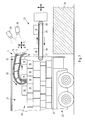
- FIG. 4 shows a belt-type conveyor device according to the invention in a schematic side view
- FIG. 5 shows the auto-adaptive adjustment of the finger unit to an item of piece goods in accordance with a method according to the invention, in a schematic side view
- FIG. 6 shows the functional principle of a first method according to the invention in a schematic illustration
- FIG. 7 shows the functional principle of a second method according to the invention in a schematic illustration
- FIGS. 8A-C show a functional principle of a third method according to the invention in a schematic illustration.
- FIG. 1 illustrates a finger unit 1 which permits an auto-adaptive deformation.
- the finger unit 1 has two flank elements 2 , 3 which, in the case of the illustrated and thus preferred finger unit 1 , run jointly from one end 4 of the finger unit 1 to the opposite end 5 of the finger unit 1 . Furthermore, in a longitudinal direction of the finger unit 1 , the flank elements 2 , 3 move continuously closer together. Whereas the flank elements 2 , 3 are spaced apart from one another at one end 4 of the finger unit 1 , the flank elements 2 , 3 are directly connected to one another at the other end 5 of the finger unit 1 . Therefore, a finger unit 1 is realized which narrows, and tapers conically, in one direction.
- Webs 6 are provided, so as to be distributed over the length of the finger unit 1 , between the flank elements 2 , 3 , by way of which webs the flank elements 2 , 3 are connected to one another.
- the webs 6 are, at the two opposite ends 7 , 8 , articulatedly connected to the flank elements 2 , 3 by way of joints. It would alternatively be possible for the webs 6 to be of flexible form.
- the webs 6 are distributed at uniform intervals over the length of the finger unit 1 . This is however not imperatively necessary. It is also not imperatively necessary for the webs 6 to run parallel to one another, as in the case of the illustrated finger unit 1 . It is however preferable for the webs 6 to form, with each of the flank elements 2 , 3 , an acute angle ⁇ on one side and an obtuse angle 3 on the opposite side.
- flank elements 2 , 3 are of flexible form, such that the flank elements 2 , 3 can bend about an axis perpendicular to the longitudinal extent of the finger unit 1 , as illustrated in particular in FIGS. 2A-C .
- the flank elements 2 , 3 are formed from a flexible plastic or for example from rubber.
- the webs 6 may likewise be formed from plastic or for example from a metal, because the webs 6 need not exhibit flexibility.
- FIG. 2A the finger unit 1 from FIG. 1 is illustrated in an initial position, in which the finger unit 1 is present in a straightened orientation, wherein the free ends of the flank elements 2 , 3 are arranged in a plane E.
- the flank elements 2 , 3 are, in this position, formed at least substantially symmetrically with respect to one another.
- the finger unit 1 curves downward owing to the connection of the flank elements 2 , 3 by way of the multiplicity of webs 6 . In this way, that end 5 of the finger unit 1 which is illustrated on the right is adjusted downward.
- the finger unit 1 curves upward in an analogous manner, as per FIG. 2C , wherein the corresponding end 5 of the finger unit 1 is adjusted upward when the free end of the lower flank element 3 is displaced forward out of the plane E in the longitudinal direction of the finger unit 1 in the direction of the curving tip of the finger unit 1 . It also emerges from FIGS. 2A-C that the struts 6 between the flank elements 2 , 3 are inclined in different directions in the event of the finger unit 1 curving in opposite directions.
- a drive unit (not illustrated) may be provided.
- suitable drive units are known from the prior art.
- Suitable drive units may for example have at least one linear drive. It is thus possible for at least one flank element 2 , 3 to be adjusted forward and backward in the longitudinal direction of the finger unit 1 without problems.
- flank elements are then arranged so as to be distributed, in particular uniformly, about a longitudinal axis of the finger unit.
- the multiple flank elements may then converge, in particular by way of free ends, at a common tip of the finger unit.
- the webs may preferably connect in each case all flank elements to one another.
- flank elements 2 , 3 are of strip-shaped form.
- a plate-shaped or bar-shaped form of the flank elements would however also be possible.
- the described finger unit 1 may however also be adjusted in a different manner than that illustrated in FIGS. 2A-C , specifically as per FIG. 3 , which shows an auto-adaptive adjustment of a flank element 2 , 3 of the finger unit 1 when an item of piece goods 10 presses the corresponding flank element 2 inward in relation to the finger unit 1 .
- FIG. 3 shows an auto-adaptive adjustment of a flank element 2 , 3 of the finger unit 1 when an item of piece goods 10 presses the corresponding flank element 2 inward in relation to the finger unit 1 .
- the corresponding flank element 2 is displaced locally inward in relation to the finger unit 1 in the direction of the pressure force F, which has the effect, owing to the coupling of the flank elements 2 , 3 by way of the webs 6 , that the flank element 2 is, at a different location, curved in the direction of the item of piece goods 10 , specifically in the direction of the two connected-together ends 11 of the flank elements 1 at that end 5 of the finger unit 1 which is illustrated on the left, that is to say is adjusted outward in relation to the finger unit 1 counter to the pressure force F, or in the present case upward.
- the item of piece goods 10 is partially gripped by the finger unit 1 .
- FIG. 4 illustrates a belt-type conveyor device 12 in the case of which the supporting structure 13 of the belt-type conveyor device 12 is composed of a finger unit 1 as per FIG. 1 .
- the conveyor belt 14 of the belt-type conveyor device 12 circulates around the supporting structure 13 and thus around the finger unit 1 .
- the illustrated and thus preferred belt-type conveyor device 12 has multiple deflections in the form of deflection rollers 15 , 16 , 17 .
- One deflection roller 15 is provided at the connected-together ends 11 of the flank elements 2 , 3 , wherein the deflection roller 15 is ultimately borne and supported by the corresponding end 5 of the finger unit 1 .
- a drive 18 is provided which, in the case of the illustrated and thus preferred belt-type conveyor device 12 , can drive the conveyor belt 14 in different directions.
- the drive 18 is realized by way of a drive roller 19 which can be adjusted as required for the purposes of tensioning the conveyor belt 14 , for example in a longitudinal direction of the finger unit 1 .
- a toothing may be provided on the conveyor belt 14 , which toothing meshes with a toothing of the drive roller 19 .
- the supporting structure 13 around which the conveyor belt 14 circulates may have not only the finger unit 1 but also further supporting structure parts.
- the conveyor belt 14 is guided along the flank elements 2 , 3 , specifically in such proximity that the conveyor belt 14 can, as required, be pressed against a flank element 2 , 3 by an item of piece goods 10 .
- the finger unit 1 can be adjusted auto-adaptively in relation to the corresponding item of piece goods 10 , as has been described in principle in conjunction with FIG. 3 .
- the flank elements 2 , 3 can be displaced relative to one another in a longitudinal direction of the finger unit 1 , as has been described in principle in conjunction with FIGS. 2A-C .
- the conveyor belt 14 With the associated adjustment of an end 5 of the finger unit 1 in a direction perpendicular to the longitudinal extent of the finger unit 1 , the conveyor belt 14 , and the profile thereof around the finger unit 1 , are also adjusted. If it is sought for the conveyor belt 14 to be guided along the flank elements 2 , 3 with a small spacing thereto even in the case of a curved finger unit 1 , it is necessary, as required, for further devices (not illustrated) for the positioning of the conveyor belt 14 to be provided, between the deflection rollers 15 , 16 , 17 , adjacent to the flank elements 2 , 3 or to the at least one flank element 2 , 3 .
- FIG. 5 illustrates the use of a finger unit 1 for the removal of piece goods 10 which are situated on a stack 20 of piece goods 10 in the form of packages.
- the finger unit 1 is moved over the stack 20 in an approach direction A toward the rear side of the stack 20 in relation to the finger unit 1 , in order to bring the finger unit 1 in overlap with the stack 20 .
- the finger unit 1 is lowered onto the stack 20 of piece goods 10 in a gripping direction G until the finger unit 1 presses partially against the item of piece goods 10 .
- the finger unit 1 is moved in a transport direction T.
- the transport direction T is oriented oppositely to the approach direction A and perpendicular to the gripping direction G. This situation may however be deviated from as required.
- the gripping direction G should have a movement component which is perpendicular both to the approach direction A and to the transport direction T.
- the finger unit 1 and the stack 20 as per FIG. 5 are, in FIG. 6 , provided in a loading space 21 of a heavy goods vehicle, trailer or semitrailer 22 .
- the finger unit 1 is in this case held in movable fashion such that the finger unit 1 can be moved both forward and backward and upward and downward. It is thus possible for the finger unit 1 to remove piece goods 10 from the stack 20 and gradually clear away even a very deep stack 20 of piece goods 10 .
- a belt-type conveyor device 23 may be positioned laterally with respect to the stack 20 of piece goods 10 , so as to be spaced apart therefrom or adjacent thereto, in order to collect and transport away the piece goods 10 that have been removed from the stack 20 by the finger unit 1 .
- the belt-type conveyor device 23 is positioned for example on a loading ramp 24 .
- the belt-type conveyor device 23 can be moved forward and backward, and may in particular be telescopable. It is accordingly possible for the belt-type conveyor installation 23 to be moved gradually further into the loading space 21 as the stack 20 is gradually cleared away.
- the belt-type conveyor device 23 comprises a support structure 25 around which the conveyor belt 26 circulates around deflections in the form of deflection rollers 27 , 28 in the direction illustrated by the arrows.
- multiple conveyor belts 26 it is also possible for multiple conveyor belts 26 to be provided one behind the other for the purposes of transporting the piece goods 10 .
- At least two optical sensors 29 , 30 in the form of cameras are provided for controlling the movement of the finger unit 1 .
- the sensors 29 , 30 capture the stack 20 or at least an upper part thereof. From the images and the position of the sensors 29 , 30 relative to one another, at least a part of the contour of the stack 20 and the position of the contour is captured as a distance and direction in relation to the sensors 29 , 30 .
- the at least partial determination of the position and contour of the stack 20 is realized by way of the known method of so-called triangulation.
- one, preferably optical, sensor it is however also possible for one, preferably optical, sensor to be adequate for controlling the movement of the finger unit 1 . It is however likewise possible for more than two, preferably optical, sensors to be provided. Then, potentially even more precise control and/or spatially more complex control is possible, for example because the stack can be captured in three dimensions more effectively and/or with greater precision.
- the position of the belt-type conveyor unit 23 can likewise be lowered. It is thus possible for the piece goods 10 to always be moved by the finger unit 1 onto the conveyor belt 26 of the belt-type conveyor device 23 under the action of gravitational force without problems. It would be possible for the belt-type conveyor device 23 to be adjusted initially to a height which lies slightly above the loading floor 31 of the loading space 21 .
- the finger unit 1 When the finger unit 1 has removed a partially gripped item of piece goods 10 from the stack 20 , the item of piece goods 10 can thus fall downward onto the belt-type conveyor device 23 . Since the flank elements 2 , 3 of the illustrated finger unit 1 are of elastic form and impart a restoring force counter to the deformation during the partial gripping of the item of piece goods 10 , the item of piece goods 10 is no longer held by the finger unit 1 after having been pulled from the stack 20 . The item of piece goods 10 falls downward and the finger unit 1 returns into its straightened initial position owing to the restoring force of the flank elements 2 , 3 . The finger unit 1 can then be introduced into the loading space 21 again, above the remaining stack 20 , in the approach direction A.
- the finger unit 1 When the finger unit 1 is then positioned above the stack 20 again, the finger unit 1 can be moved downward again in the gripping direction G and at least partially grip at least one further item of piece goods 10 , which is then, by way of a movement of the finger unit 1 , removed from the stack in the transport direction T and moved onto the belt-type conveyor device 23 , by way of which the at least one item of piece goods 10 is transported away. It is self-evident that, in addition to the at least one item of piece goods 10 that is gripped by the finger unit 1 , it is also possible, in one step, for further piece goods 10 to jointly be removed from the stack 20 , specifically for example piece goods 10 which are situated at the edge of the stack 20 .
- the finger unit 1 may extend at least substantially over the width of the stack 20 and/or of the loading space 21 in order to be able to clear away the stack 20 over its entire width simultaneously.
- multiple finger units 1 may be arranged adjacent to one another so as to be distributed over the width of the stack 20 and/or of the loading space. Said multiple finger units may, as required, be controlled and/or moved independently of one another in order to realize effective handling of piece goods. It may alternatively or additionally be expedient for the finger unit 1 or each finger unit to be assigned a dedicated drive as required.
- the finger unit it is then possible for the finger unit to be moved or for the finger units to be moved in particular independently of one another.
- a simplification in terms of method and construction may however also be provided, as required, in that multiple finger units 1 , in particular all of the finger units 1 , can be combined to form a hand unit. It is then possible, by way of the movement of the hand, which bears multiple finger units 1 , to effect a common movement of the finger units 1 which are held on the hand unit, without the finger units 1 having to be moved separately.
- the described method may in this case be performed using only one hand unit or using a multiplicity of hand units. It is thus possible, for example, to realize an adaptation to varying stack widths or loading space widths.
- the piece goods 10 in particular packages, have been brought together to form stacks 20 . It would however alternatively also be possible for the piece goods 10 to have been brought together to form a pile, or to have at least partially been brought together to form a pile. The described methods and devices would then be implemented analogously as required.
- FIG. 7 illustrates the method principle as per FIG. 6 , with the difference that a finger unit 1 as part of a belt-type conveyor device 12 is used.
- a conveyor belt 14 circulates around the finger unit 1 , which functions as supporting structure 13 , in the direction of the arrows.
- the item of piece goods 10 at least partially gripped owing to the auto-adaptive adjustment of the finger unit 1 is, owing to the movement of the conveyor belt 14 , moved from the stack 20 in the transport direction T and subsequently falls onto the belt-type conveyor device 12 , which is provided at a slightly lower level.
- an auto-adaptive deformation of the finger unit 1 can be maintained, such that good contact between the conveyor belt 14 and the item of piece goods 10 is maintained at all times.
- the auto-adaptive deformation can travel together with the item of piece goods 10 along the belt-type conveyor device 12 or along the finger unit 1 , wherein the auto-adaptive deformation will vary as required.
- the finger unit 1 has to be adjusted back and forth in the transport direction T and approach direction A less frequently as required.
- the finger unit 1 or of the belt-type conveyor device 12 in the gripping direction G it is possible for gradually further piece goods 10 to be gripped in auto-adaptive fashion and transported away in the transport direction T.
- the stack 20 can, as required, be cleared away at least to a not inconsiderable extent without the finger unit 1 having to be adjusted in the transport direction T and/or in the approach direction A.
- belt-type conveyor devices 12 may be moved and/or controlled separately or else may be joined together to form at least one hand unit, such that the belt-type conveyor devices 12 can be moved and/or controlled jointly by way of the hand unit.
- the single belt-type conveyor device 12 or the multiplicity of belt-type conveyor devices 12 extends over at least substantially the entire width of the stack 20 , pile and/or loading space 21 .
- FIGS. 8A-C illustrate a further method process.
- a belt-type conveyor device 12 having a finger element 1 at least as part of the supporting structure 13 is used and is positioned adjacent or behind the stack 20 of piece goods 10 , in particular packages.
- the piece goods 10 are now moved onto the belt-type conveyor device 12 from the upper end of the stack 20 . This may be performed manually or else using at least one further finger unit 1 as per FIG. 6 and/or at least one further belt-type conveyor device 12 as per FIG. 7 .
- the free end of the belt-type conveyor device 12 has a finger unit 1 as a supporting structure 13 , which can be suitably curved by virtue of the flank elements 2 , 3 being adjusted relative to one another in the longitudinal direction of the finger unit 1 .
- the stack 20 of piece goods 10 is, adjacent to the belt-type conveyor device 12 , very tall.
- the front end of the belt-type conveyor device 12 is, by way of a corresponding adjustment of the finger unit 1 , bent upward, as illustrated in FIG. 8A .
- the adjustment is performed as has already been described in principle in conjunction with FIGS. 2A-C .
- the height of the stack 20 adjacent to the belt-type conveyor device 12 is also lower. In order that this does not lead to an impairment of the transporting-away of the piece goods 10 , the curvature of the free end of the belt-type conveyor device 12 can be at least partially eliminated, as illustrated in FIG. 8B . In this position, the finger unit 1 is substantially straightened. Since the height of the stack 20 is smaller, it is the case in this position of the belt-type conveyor device 12 , too, that no piece goods 10 or packages are damaged.
- the belt-type conveyor device 12 When the stack 20 has been cleared away yet further, only a very small height of the stack 20 remains, at any rate adjacent to the belt-type conveyor device 12 . In order that the piece goods 10 can then still fall onto the belt-type conveyor device 12 , the belt-type conveyor device 12 must, at least in the region of the free end, be lowered almost to the loading floor 31 of the loading space 21 , as illustrated in FIG. 8C . This is achieved for example by virtue of the finger unit 1 of the belt-type conveyor device 12 being curved, proceeding from the straightened position as per FIG. 8B , in the opposite direction to that in FIG. 8A . The finger unit 1 is thus curved not upward but downward.
- the belt-type conveyor device 12 As a result of the targeted curvature of the free end of the belt-type conveyor device 12 , a linear height adjustment of the belt-type conveyor device 12 itself is optionally rendered unnecessary. Nevertheless, such a height adjustment is self-evidently possible. Nevertheless, it may be expedient if the belt-type conveyor device 12 can be moved forward and backward, for example in stepped fashion, in order that it can extend as far as necessary into the loading space 21 . Therefore, it is basically expedient for the belt-type conveyor device 12 to be in the form of a telescopic belt-type conveyor.
- the belt-type conveyor 12 illustrated in FIGS. 8A-C is furthermore equipped with a finger unit 1 which exhibits such flexibility that the piece goods 10 , as they are transported along the belt-type conveyor device 12 , can effect an auto-adaptive adjustment of the flank elements 2 , if the piece goods 10 are heavy enough.
- the piece goods 10 press the upper flank element 2 downward, such that, owing to the coupling of the flank elements 2 , 3 by the webs 6 , the free end 5 of the finger unit 1 or of the belt-type conveyor device 12 is curved upward.
- the corresponding item of piece goods 10 is thus at least partially gripped, and the transportation along the belt-type conveyor device 12 is stabilized.
Landscapes
- Engineering & Computer Science (AREA)
- Mechanical Engineering (AREA)
- Aviation & Aerospace Engineering (AREA)
- Stacking Of Articles And Auxiliary Devices (AREA)
- Specific Conveyance Elements (AREA)
- Folding Of Thin Sheet-Like Materials, Special Discharging Devices, And Others (AREA)
Applications Claiming Priority (3)
| Application Number | Priority Date | Filing Date | Title |
|---|---|---|---|
| DE102015116720.4 | 2015-10-01 | ||
| DE102015116720.4A DE102015116720B4 (de) | 2015-10-01 | 2015-10-01 | Verfahren und Vorrichtung zum Fördern von Stückgütern von einem Stapel oder Haufen |
| DE102015116720 | 2015-10-01 |
Publications (2)
| Publication Number | Publication Date |
|---|---|
| US20170096301A1 US20170096301A1 (en) | 2017-04-06 |
| US10035657B2 true US10035657B2 (en) | 2018-07-31 |
Family
ID=57068011
Family Applications (1)
| Application Number | Title | Priority Date | Filing Date |
|---|---|---|---|
| US15/279,712 Active US10035657B2 (en) | 2015-10-01 | 2016-09-29 | Method and device for conveying piece goods from a stack or pile |
Country Status (4)
| Country | Link |
|---|---|
| US (1) | US10035657B2 (de) |
| EP (1) | EP3150518B1 (de) |
| CN (1) | CN106882599B (de) |
| DE (1) | DE102015116720B4 (de) |
Cited By (6)
| Publication number | Priority date | Publication date | Assignee | Title |
|---|---|---|---|---|
| US10611585B2 (en) * | 2018-08-31 | 2020-04-07 | Thomas Alfred Sullivan | Systems and methods for unloading a pickup truck bed |
| US20210032051A1 (en) * | 2019-07-31 | 2021-02-04 | Siemens Logistics Llc | Automated unloading speed control |
| US20220097973A1 (en) * | 2020-09-30 | 2022-03-31 | Deutsche Post Ag | Loading device and method for loading a container with packages |
| US11434090B2 (en) * | 2018-11-06 | 2022-09-06 | Siemens Logistics Llc | System and equipment for automatic unloading of parcels |
| US20230137246A1 (en) * | 2021-11-04 | 2023-05-04 | Zebra Technologies Corporation | System and Method for Bulk Transfer-Based Container Unloading |
| WO2024155801A1 (en) * | 2023-01-20 | 2024-07-25 | Harvest Moon Automation Inc. | Adaptive gripper for robotics and other applications |
Families Citing this family (8)
| Publication number | Priority date | Publication date | Assignee | Title |
|---|---|---|---|---|
| DE102016109313A1 (de) * | 2016-05-20 | 2017-11-23 | Deutsche Post Ag | Rutsche für Stückgut und Verfahren zur Verwendung einer solchen Rutsche |
| EP3441331B8 (de) * | 2017-08-09 | 2022-11-02 | Körber Supply Chain Logistics GmbH | Verfahren zum handling von sortierstücken mit überwachten teleskopförderbändern |
| CN109278830A (zh) * | 2018-11-22 | 2019-01-29 | 四川大学 | 卸载装置及物件转运系统 |
| JP7261069B2 (ja) * | 2019-04-09 | 2023-04-19 | 川崎重工業株式会社 | ロボットハンド、ロボット及びロボットシステム |
| DE102020116880A1 (de) * | 2020-06-26 | 2021-12-30 | Deutsche Post Ag | Verfahren und Vorrichtung zum Entladen eines Packstücke aufweisenden Behälters |
| DE102020126448B4 (de) * | 2020-10-08 | 2022-11-10 | Deutsche Post Ag | Verfahren und Vorrichtung zum Beladen von Behältern mit Packstücken |
| DE102020215228B3 (de) | 2020-12-02 | 2022-03-17 | Festo Se & Co. Kg | Greifvorrichtung zum Greifen von Objekten und Verfahren zum Betreiben einer solchen Greifvorrichtung |
| CN114419150B (zh) | 2021-12-21 | 2025-09-16 | 未来机器人(深圳)有限公司 | 叉车取货方法、装置、计算机设备、存储介质 |
Citations (20)
| Publication number | Priority date | Publication date | Assignee | Title |
|---|---|---|---|---|
| DE3817013A1 (de) | 1988-05-09 | 1989-11-23 | Behn Maschf | Vorrichtung zum ergreifen, transportieren und palettieren eines gefuellten sackes |
| US5256021A (en) * | 1991-06-04 | 1993-10-26 | Wolf James M | Telescope vehicle loading and unloading system |
| US5351809A (en) * | 1993-04-26 | 1994-10-04 | Rapistan Demag Corporation | Multiple-stage extendable conveyor |
| AT401633B (de) | 1995-01-12 | 1996-10-25 | Favre Bulle Bernard Dr | Sensorgestütztes roboter-greifersystem nach dem tentakelprinzip |
| US5685416A (en) * | 1995-02-13 | 1997-11-11 | United Parcel Service Of America, Inc. | Material conveying apparatus and method |
| US5924839A (en) * | 1992-08-20 | 1999-07-20 | Kolbus Gmbh & Co. Kg | Rearrangement method and apparatus |
| US20010009217A1 (en) | 1996-04-24 | 2001-07-26 | Gilmore Phillip J. | Extendable trailer loader/unloader with user interface section |
| US6484862B1 (en) * | 2000-07-18 | 2002-11-26 | Rapistan Systems Advertising Corp. | Extendable gravity loader |
| DE102005010380A1 (de) | 2005-03-07 | 2006-09-14 | Fraunhofer-Gesellschaft zur Förderung der angewandten Forschung e.V. | Greifwerkzeug mit selbstadaptiver Kinematik |
| DE102007017416B3 (de) | 2007-04-13 | 2008-06-19 | Festo Ag & Co. | Sortiervorrichtung |
| WO2010108662A1 (de) | 2009-03-26 | 2010-09-30 | Festo Ag & Co. Kg | Fluidtechnisches gerät, insbesondere greifervorrichtung |
| EP2241403A1 (de) | 2009-04-19 | 2010-10-20 | Bannasch, Rudolf | Manipulatorwerkzeug und Halte- und/oder Spreizwerkzeug mit wenigstens einem Manipulatorwerkzeug |
| DE102011115951A1 (de) | 2011-10-13 | 2013-04-18 | BIBA - Bremer Institut für Produktion und Logistik GmbH | Verfahren und Greifwerkzeug zur Handhabung, insbesondere Förderung, von unregelmäßig angeordneten Gütern,insbesondere Paketen, sowie Greifersystem mit demselben |
| US20130230373A1 (en) | 2010-04-22 | 2013-09-05 | Siemens Industry, Inc. | Automated Unloader Base Belt and Container |
| US8651794B2 (en) * | 2010-04-22 | 2014-02-18 | Siemens Industry, Inc. | Automated bed-loaded container unloader and method |
| US8834336B2 (en) * | 2008-05-29 | 2014-09-16 | Bhs Corrugated Maschinen- Und Anlagenbau Gmbh | Folding device |
| US20140341694A1 (en) | 2013-05-17 | 2014-11-20 | Intelligrated Headquarters, Llc | Robotic carton unloader |
| US9290354B2 (en) * | 2008-05-29 | 2016-03-22 | Bhs Corrugated Maschinen-Und Anlagenbau Gmbh | Continuous folding process |
| US9738466B2 (en) * | 2010-04-22 | 2017-08-22 | Siemens Industry, Inc. | Automated bed-loaded container unloader and method |
| US9776801B2 (en) * | 2014-03-11 | 2017-10-03 | Deutsche Post Ag | System with telescopic conveyor and method therefor |
Family Cites Families (2)
| Publication number | Priority date | Publication date | Assignee | Title |
|---|---|---|---|---|
| GB201103450D0 (en) * | 2011-03-01 | 2011-04-13 | Meadwestvaco Packaging Systems | Apparatus and method of manipulation of articles |
| CN203419559U (zh) * | 2013-08-06 | 2014-02-05 | 昆明昆船物流信息产业有限公司 | 一种烟包自动对正组盘系统 |
-
2015
- 2015-10-01 DE DE102015116720.4A patent/DE102015116720B4/de not_active Expired - Fee Related
-
2016
- 2016-09-29 US US15/279,712 patent/US10035657B2/en active Active
- 2016-09-30 CN CN201610872181.6A patent/CN106882599B/zh active Active
- 2016-10-04 EP EP16192193.7A patent/EP3150518B1/de active Active
Patent Citations (21)
| Publication number | Priority date | Publication date | Assignee | Title |
|---|---|---|---|---|
| DE3817013A1 (de) | 1988-05-09 | 1989-11-23 | Behn Maschf | Vorrichtung zum ergreifen, transportieren und palettieren eines gefuellten sackes |
| US5256021A (en) * | 1991-06-04 | 1993-10-26 | Wolf James M | Telescope vehicle loading and unloading system |
| US5924839A (en) * | 1992-08-20 | 1999-07-20 | Kolbus Gmbh & Co. Kg | Rearrangement method and apparatus |
| US5351809A (en) * | 1993-04-26 | 1994-10-04 | Rapistan Demag Corporation | Multiple-stage extendable conveyor |
| AT401633B (de) | 1995-01-12 | 1996-10-25 | Favre Bulle Bernard Dr | Sensorgestütztes roboter-greifersystem nach dem tentakelprinzip |
| US5685416A (en) * | 1995-02-13 | 1997-11-11 | United Parcel Service Of America, Inc. | Material conveying apparatus and method |
| US20010009217A1 (en) | 1996-04-24 | 2001-07-26 | Gilmore Phillip J. | Extendable trailer loader/unloader with user interface section |
| US6484862B1 (en) * | 2000-07-18 | 2002-11-26 | Rapistan Systems Advertising Corp. | Extendable gravity loader |
| DE102005010380A1 (de) | 2005-03-07 | 2006-09-14 | Fraunhofer-Gesellschaft zur Förderung der angewandten Forschung e.V. | Greifwerkzeug mit selbstadaptiver Kinematik |
| DE102007017416B3 (de) | 2007-04-13 | 2008-06-19 | Festo Ag & Co. | Sortiervorrichtung |
| US8834336B2 (en) * | 2008-05-29 | 2014-09-16 | Bhs Corrugated Maschinen- Und Anlagenbau Gmbh | Folding device |
| US9290354B2 (en) * | 2008-05-29 | 2016-03-22 | Bhs Corrugated Maschinen-Und Anlagenbau Gmbh | Continuous folding process |
| WO2010108662A1 (de) | 2009-03-26 | 2010-09-30 | Festo Ag & Co. Kg | Fluidtechnisches gerät, insbesondere greifervorrichtung |
| EP2241403A1 (de) | 2009-04-19 | 2010-10-20 | Bannasch, Rudolf | Manipulatorwerkzeug und Halte- und/oder Spreizwerkzeug mit wenigstens einem Manipulatorwerkzeug |
| US20130230373A1 (en) | 2010-04-22 | 2013-09-05 | Siemens Industry, Inc. | Automated Unloader Base Belt and Container |
| US8651794B2 (en) * | 2010-04-22 | 2014-02-18 | Siemens Industry, Inc. | Automated bed-loaded container unloader and method |
| US9321601B2 (en) * | 2010-04-22 | 2016-04-26 | Siemens Industry, Inc. | Automated unloader base belt and container |
| US9738466B2 (en) * | 2010-04-22 | 2017-08-22 | Siemens Industry, Inc. | Automated bed-loaded container unloader and method |
| DE102011115951A1 (de) | 2011-10-13 | 2013-04-18 | BIBA - Bremer Institut für Produktion und Logistik GmbH | Verfahren und Greifwerkzeug zur Handhabung, insbesondere Förderung, von unregelmäßig angeordneten Gütern,insbesondere Paketen, sowie Greifersystem mit demselben |
| US20140341694A1 (en) | 2013-05-17 | 2014-11-20 | Intelligrated Headquarters, Llc | Robotic carton unloader |
| US9776801B2 (en) * | 2014-03-11 | 2017-10-03 | Deutsche Post Ag | System with telescopic conveyor and method therefor |
Non-Patent Citations (1)
| Title |
|---|
| Johann Wolfgang Von Goethe, "Bionics in Progress ist ein Lehrprojekt für das WS 06/07 und SS 07 für Studenten im Hauptstudium aus", Article, Dec. 31, 2007, 9 pages. |
Cited By (9)
| Publication number | Priority date | Publication date | Assignee | Title |
|---|---|---|---|---|
| US10611585B2 (en) * | 2018-08-31 | 2020-04-07 | Thomas Alfred Sullivan | Systems and methods for unloading a pickup truck bed |
| US11434090B2 (en) * | 2018-11-06 | 2022-09-06 | Siemens Logistics Llc | System and equipment for automatic unloading of parcels |
| US20210032051A1 (en) * | 2019-07-31 | 2021-02-04 | Siemens Logistics Llc | Automated unloading speed control |
| US11702302B2 (en) * | 2019-07-31 | 2023-07-18 | Körber Supply Chain Llc | Automated unloading speed control |
| US20220097973A1 (en) * | 2020-09-30 | 2022-03-31 | Deutsche Post Ag | Loading device and method for loading a container with packages |
| US12037197B2 (en) * | 2020-09-30 | 2024-07-16 | Deutsche Post Ag | Loading device and method for loading a container with packages |
| US20230137246A1 (en) * | 2021-11-04 | 2023-05-04 | Zebra Technologies Corporation | System and Method for Bulk Transfer-Based Container Unloading |
| US12606390B2 (en) * | 2021-11-04 | 2026-04-21 | Zebra Technologies Corporation | System and method for bulk transfer-based container unloading |
| WO2024155801A1 (en) * | 2023-01-20 | 2024-07-25 | Harvest Moon Automation Inc. | Adaptive gripper for robotics and other applications |
Also Published As
| Publication number | Publication date |
|---|---|
| EP3150518B1 (de) | 2018-12-05 |
| US20170096301A1 (en) | 2017-04-06 |
| CN106882599B (zh) | 2019-10-15 |
| EP3150518A1 (de) | 2017-04-05 |
| DE102015116720A1 (de) | 2017-04-06 |
| DE102015116720B4 (de) | 2019-03-07 |
| CN106882599A (zh) | 2017-06-23 |
Similar Documents
| Publication | Publication Date | Title |
|---|---|---|
| US10035657B2 (en) | Method and device for conveying piece goods from a stack or pile | |
| US9604797B2 (en) | Apparatus and process for unloading load items from a loading space | |
| CN115485219B (zh) | 视觉辅助机器人化卸垛机 | |
| US11613436B2 (en) | Method and device for loading containers with packages | |
| KR102129743B1 (ko) | 스파우트가 부착된 백의 공급 장치 | |
| US12064867B2 (en) | Method and device for unloading a container having packages | |
| KR102129742B1 (ko) | 스파우트가 부착된 백의 공급 장치 | |
| US20160023851A1 (en) | Gripper head for removing packages of articles from a stack | |
| JP3141087B2 (ja) | 物体の積み卸しを行なう装置 | |
| US9334146B2 (en) | Stacker and method for displacing goods | |
| US12037197B2 (en) | Loading device and method for loading a container with packages | |
| CN107250011A (zh) | 用于将扁平元件堆提供给加工装置的供料系统 | |
| US11155421B2 (en) | Conveying device and method for converting a serially transported piece goods stream into a parallelly transported piece goods stream | |
| DE102017002478A1 (de) | Vorrichtung zur aufnahme von gestapelten objekten | |
| CN107250010A (zh) | 用于将可堆叠的扁平元件堆传送到加工装置的传送系统 | |
| JP6564908B2 (ja) | 物品供給装置 | |
| CN106029533B (zh) | 用于转运装货单元的装置和方法 | |
| US7361130B2 (en) | System for production and subsequent palletizing of tube segments, bags or sacks | |
| DK3061712T3 (en) | Apparatus and method for unloading roll containers or swap body | |
| JP2015218045A (ja) | 物品供給装置 | |
| US12312178B2 (en) | Telescoping conveyor | |
| EP3505470B1 (de) | Handhabungsvorrichtung, mobiles autonomes flurförderzeug, stationäre kommissionieranlage und ein verfahren zum betreiben der handhabungsvorrichtung | |
| CN212221917U (zh) | 感光印刷版下料辅助设备 | |
| KR102055521B1 (ko) | 2단 컨베이어를 이용한 이송장치 | |
| JP2002176856A (ja) | 苗箱段積み装置 |
Legal Events
| Date | Code | Title | Description |
|---|---|---|---|
| AS | Assignment |
Owner name: DEUTSCHE POST AG, GERMANY Free format text: ASSIGNMENT OF ASSIGNORS INTEREST;ASSIGNORS:HARTMANN, BERND;GRAFE, WOLFRAM;REEL/FRAME:039979/0021 Effective date: 20161006 |
|
| STCF | Information on status: patent grant |
Free format text: PATENTED CASE |
|
| MAFP | Maintenance fee payment |
Free format text: PAYMENT OF MAINTENANCE FEE, 4TH YEAR, LARGE ENTITY (ORIGINAL EVENT CODE: M1551); ENTITY STATUS OF PATENT OWNER: LARGE ENTITY Year of fee payment: 4 |
|
| MAFP | Maintenance fee payment |
Free format text: PAYMENT OF MAINTENANCE FEE, 8TH YEAR, LARGE ENTITY (ORIGINAL EVENT CODE: M1552); ENTITY STATUS OF PATENT OWNER: LARGE ENTITY Year of fee payment: 8 |