US10029255B2 - Liquid handling device - Google Patents
Liquid handling device Download PDFInfo
- Publication number
- US10029255B2 US10029255B2 US15/117,030 US201515117030A US10029255B2 US 10029255 B2 US10029255 B2 US 10029255B2 US 201515117030 A US201515117030 A US 201515117030A US 10029255 B2 US10029255 B2 US 10029255B2
- Authority
- US
- United States
- Prior art keywords
- channel
- chip
- film
- partition wall
- liquid
- Prior art date
- Legal status (The legal status is an assumption and is not a legal conclusion. Google has not performed a legal analysis and makes no representation as to the accuracy of the status listed.)
- Active
Links
Images


Classifications
-
- B—PERFORMING OPERATIONS; TRANSPORTING
- B01—PHYSICAL OR CHEMICAL PROCESSES OR APPARATUS IN GENERAL
- B01L—CHEMICAL OR PHYSICAL LABORATORY APPARATUS FOR GENERAL USE
- B01L3/00—Containers or dishes for laboratory use, e.g. laboratory glassware; Droppers
- B01L3/50—Containers for the purpose of retaining a material to be analysed, e.g. test tubes
- B01L3/502—Containers for the purpose of retaining a material to be analysed, e.g. test tubes with fluid transport, e.g. in multi-compartment structures
- B01L3/5027—Containers for the purpose of retaining a material to be analysed, e.g. test tubes with fluid transport, e.g. in multi-compartment structures by integrated microfluidic structures, i.e. dimensions of channels and chambers are such that surface tension forces are important, e.g. lab-on-a-chip
- B01L3/502738—Containers for the purpose of retaining a material to be analysed, e.g. test tubes with fluid transport, e.g. in multi-compartment structures by integrated microfluidic structures, i.e. dimensions of channels and chambers are such that surface tension forces are important, e.g. lab-on-a-chip characterised by integrated valves
-
- B—PERFORMING OPERATIONS; TRANSPORTING
- B01—PHYSICAL OR CHEMICAL PROCESSES OR APPARATUS IN GENERAL
- B01L—CHEMICAL OR PHYSICAL LABORATORY APPARATUS FOR GENERAL USE
- B01L3/00—Containers or dishes for laboratory use, e.g. laboratory glassware; Droppers
- B01L3/50—Containers for the purpose of retaining a material to be analysed, e.g. test tubes
- B01L3/502—Containers for the purpose of retaining a material to be analysed, e.g. test tubes with fluid transport, e.g. in multi-compartment structures
- B01L3/5027—Containers for the purpose of retaining a material to be analysed, e.g. test tubes with fluid transport, e.g. in multi-compartment structures by integrated microfluidic structures, i.e. dimensions of channels and chambers are such that surface tension forces are important, e.g. lab-on-a-chip
- B01L3/502715—Containers for the purpose of retaining a material to be analysed, e.g. test tubes with fluid transport, e.g. in multi-compartment structures by integrated microfluidic structures, i.e. dimensions of channels and chambers are such that surface tension forces are important, e.g. lab-on-a-chip characterised by interfacing components, e.g. fluidic, electrical, optical or mechanical interfaces
-
- B—PERFORMING OPERATIONS; TRANSPORTING
- B01—PHYSICAL OR CHEMICAL PROCESSES OR APPARATUS IN GENERAL
- B01L—CHEMICAL OR PHYSICAL LABORATORY APPARATUS FOR GENERAL USE
- B01L3/00—Containers or dishes for laboratory use, e.g. laboratory glassware; Droppers
- B01L3/50—Containers for the purpose of retaining a material to be analysed, e.g. test tubes
- B01L3/502—Containers for the purpose of retaining a material to be analysed, e.g. test tubes with fluid transport, e.g. in multi-compartment structures
- B01L3/5027—Containers for the purpose of retaining a material to be analysed, e.g. test tubes with fluid transport, e.g. in multi-compartment structures by integrated microfluidic structures, i.e. dimensions of channels and chambers are such that surface tension forces are important, e.g. lab-on-a-chip
- B01L3/50273—Containers for the purpose of retaining a material to be analysed, e.g. test tubes with fluid transport, e.g. in multi-compartment structures by integrated microfluidic structures, i.e. dimensions of channels and chambers are such that surface tension forces are important, e.g. lab-on-a-chip characterised by the means or forces applied to move the fluids
-
- F—MECHANICAL ENGINEERING; LIGHTING; HEATING; WEAPONS; BLASTING
- F16—ENGINEERING ELEMENTS AND UNITS; GENERAL MEASURES FOR PRODUCING AND MAINTAINING EFFECTIVE FUNCTIONING OF MACHINES OR INSTALLATIONS; THERMAL INSULATION IN GENERAL
- F16K—VALVES; TAPS; COCKS; ACTUATING-FLOATS; DEVICES FOR VENTING OR AERATING
- F16K99/00—Subject matter not provided for in other groups of this subclass
- F16K99/0001—Microvalves
- F16K99/0003—Constructional types of microvalves; Details of the cutting-off member
- F16K99/0015—Diaphragm or membrane valves
-
- F—MECHANICAL ENGINEERING; LIGHTING; HEATING; WEAPONS; BLASTING
- F16—ENGINEERING ELEMENTS AND UNITS; GENERAL MEASURES FOR PRODUCING AND MAINTAINING EFFECTIVE FUNCTIONING OF MACHINES OR INSTALLATIONS; THERMAL INSULATION IN GENERAL
- F16K—VALVES; TAPS; COCKS; ACTUATING-FLOATS; DEVICES FOR VENTING OR AERATING
- F16K99/00—Subject matter not provided for in other groups of this subclass
- F16K99/0001—Microvalves
- F16K99/0034—Operating means specially adapted for microvalves
- F16K99/0055—Operating means specially adapted for microvalves actuated by fluids
- F16K99/0059—Operating means specially adapted for microvalves actuated by fluids actuated by a pilot fluid
-
- B—PERFORMING OPERATIONS; TRANSPORTING
- B01—PHYSICAL OR CHEMICAL PROCESSES OR APPARATUS IN GENERAL
- B01L—CHEMICAL OR PHYSICAL LABORATORY APPARATUS FOR GENERAL USE
- B01L2200/00—Solutions for specific problems relating to chemical or physical laboratory apparatus
- B01L2200/06—Fluid handling related problems
- B01L2200/0684—Venting, avoiding backpressure, avoid gas bubbles
-
- B—PERFORMING OPERATIONS; TRANSPORTING
- B01—PHYSICAL OR CHEMICAL PROCESSES OR APPARATUS IN GENERAL
- B01L—CHEMICAL OR PHYSICAL LABORATORY APPARATUS FOR GENERAL USE
- B01L2300/00—Additional constructional details
- B01L2300/08—Geometry, shape and general structure
- B01L2300/0809—Geometry, shape and general structure rectangular shaped
- B01L2300/0816—Cards, e.g. flat sample carriers usually with flow in two horizontal directions
-
- B—PERFORMING OPERATIONS; TRANSPORTING
- B01—PHYSICAL OR CHEMICAL PROCESSES OR APPARATUS IN GENERAL
- B01L—CHEMICAL OR PHYSICAL LABORATORY APPARATUS FOR GENERAL USE
- B01L2300/00—Additional constructional details
- B01L2300/08—Geometry, shape and general structure
- B01L2300/0848—Specific forms of parts of containers
-
- B—PERFORMING OPERATIONS; TRANSPORTING
- B01—PHYSICAL OR CHEMICAL PROCESSES OR APPARATUS IN GENERAL
- B01L—CHEMICAL OR PHYSICAL LABORATORY APPARATUS FOR GENERAL USE
- B01L2300/00—Additional constructional details
- B01L2300/08—Geometry, shape and general structure
- B01L2300/0887—Laminated structure
-
- B—PERFORMING OPERATIONS; TRANSPORTING
- B01—PHYSICAL OR CHEMICAL PROCESSES OR APPARATUS IN GENERAL
- B01L—CHEMICAL OR PHYSICAL LABORATORY APPARATUS FOR GENERAL USE
- B01L2300/00—Additional constructional details
- B01L2300/14—Means for pressure control
-
- B—PERFORMING OPERATIONS; TRANSPORTING
- B01—PHYSICAL OR CHEMICAL PROCESSES OR APPARATUS IN GENERAL
- B01L—CHEMICAL OR PHYSICAL LABORATORY APPARATUS FOR GENERAL USE
- B01L2400/00—Moving or stopping fluids
- B01L2400/04—Moving fluids with specific forces or mechanical means
- B01L2400/0475—Moving fluids with specific forces or mechanical means specific mechanical means and fluid pressure
- B01L2400/0481—Moving fluids with specific forces or mechanical means specific mechanical means and fluid pressure squeezing of channels or chambers
-
- B—PERFORMING OPERATIONS; TRANSPORTING
- B01—PHYSICAL OR CHEMICAL PROCESSES OR APPARATUS IN GENERAL
- B01L—CHEMICAL OR PHYSICAL LABORATORY APPARATUS FOR GENERAL USE
- B01L2400/00—Moving or stopping fluids
- B01L2400/06—Valves, specific forms thereof
- B01L2400/0633—Valves, specific forms thereof with moving parts
- B01L2400/0638—Valves, specific forms thereof with moving parts membrane valves, flap valves
-
- B—PERFORMING OPERATIONS; TRANSPORTING
- B01—PHYSICAL OR CHEMICAL PROCESSES OR APPARATUS IN GENERAL
- B01L—CHEMICAL OR PHYSICAL LABORATORY APPARATUS FOR GENERAL USE
- B01L3/00—Containers or dishes for laboratory use, e.g. laboratory glassware; Droppers
- B01L3/50—Containers for the purpose of retaining a material to be analysed, e.g. test tubes
- B01L3/502—Containers for the purpose of retaining a material to be analysed, e.g. test tubes with fluid transport, e.g. in multi-compartment structures
- B01L3/5027—Containers for the purpose of retaining a material to be analysed, e.g. test tubes with fluid transport, e.g. in multi-compartment structures by integrated microfluidic structures, i.e. dimensions of channels and chambers are such that surface tension forces are important, e.g. lab-on-a-chip
- B01L3/502723—Containers for the purpose of retaining a material to be analysed, e.g. test tubes with fluid transport, e.g. in multi-compartment structures by integrated microfluidic structures, i.e. dimensions of channels and chambers are such that surface tension forces are important, e.g. lab-on-a-chip characterised by venting arrangements
Definitions
- the present invention relates to a liquid handling device which is used for analysis and processing of a liquid sample and the like.
- microchannel chips have been used to accurately and speedily analyze a trace substance such as protein and nucleic acid.
- Microchannel chips advantageously allow the amount of reagents or samples to be small, and are expected to be used for various uses such as laboratory tests, food tests, and environment tests.
- FIG. 1A and FIG. 1B illustrate a configuration of micro valve 10 disclosed in PTL 1.
- FIG. 1A is a plan view of micro valve 10 disclosed in PTL 1
- FIG. 1B is a sectional view taken along line a-a of FIG. 1A .
- PTL 1 discloses micro valve 10 including substrate 20 which is a flat plate, first layer 30 stacked on substrate 20 , and second layer 40 stacked on first layer 30 .
- First layer 30 includes first groove 31 , first valve groove 32 communicated with first groove 31 , second groove 33 , second valve groove 34 communicated with second groove 33 , and valve 35 disposed between first valve groove 32 and second valve groove 34 .
- first groove 31 , first valve groove 32 , second valve groove 34 and second groove 33 respectively form first channel 36 , first valve chamber 37 , second valve chamber 38 and second channel 39 .
- Second layer 40 includes, on a surface facing first layer 30 , recess 41 whose shape in a plan view has a size greater than the size of the external shape of first valve chamber 37 and second valve chamber 38 .
- recess 41 forms pressure chamber 42 .
- micro valve 10 disclosed in PTL 1, when the pressure in pressure chamber 42 is increased, first layer 30 is pushed toward substrate 20 , and valve 35 makes contact with substrate 20 , thus stopping the fluid flow from first valve chamber 37 to second valve chamber 38 . On the other hand, when the pressure in pressure chamber 42 is released, first layer 30 is sucked into recess 41 , and first layer 30 bends toward recess 41 . As a result, a gap is formed between substrate 20 and valve 35 , and fluid flows from first valve chamber 37 toward second valve chamber 38 .
- valve 35 When liquid is used as fluid which is supplied to the channel in disclosed in PTL 1, the liquid is sent from first channel 36 to the channel with valve 35 opened. By capillary action or external pressure, the liquid flows from first channel 36 to second channel 39 through a gap between valve 35 and substrate 20 . Then, valve 35 is appropriately opened and closed as described above.
- FIG. 1C is a sectional view taken along line b-b of FIG. 1A .
- the distance between first layer 30 and substrate 20 at an outer periphery portion of first valve chamber 37 is smaller than the distance between first layer 30 and substrate 20 at a center portion of first valve chamber 37 .
- first valve chamber 37 is filled with liquid in order from an outer periphery portion of first valve chamber 37 where capillarity easily occurs.
- the liquid further advances in such a manner as to turn around along the outer periphery portion of first valve chamber 37 where capillarity easily occurs.
- bubbles remain in first valve chamber 37 .
- An object of the present invention is to provide a fluid handling device which can fill a liquid channel with liquid without allowing bubbles to remain in the liquid channel.
- a liquid handling device includes a first chip, the first chip including: a first substrate having, on one surface thereof, a first groove located on an upstream side in a direction in which liquid flows, a second groove located on a downstream side in the direction in which liquid flows, and a partition wall disposed between the first groove and the second groove; and a first film configured to cover the partition wall, one end of the first groove on the partition wall side, and one end of the second groove on the partition wall side, and including a diaphragm part whose center is located on the first groove, the diaphragm part having a circular shape in plan view, the first film being bonded on the one surface of the first substrate except for the diaphragm part.
- a liquid channel and a discharge hole or a discharge channel are formed in the first chip, the liquid channel including a first channel disposed on the first groove side and configured of the first groove, the partition wall and the first film, and a second channel disposed on the second groove side and configured of the second groove, the partition wall and the first film, the discharge hole or the discharge channel being configured to open at the first channel between a center of the diaphragm part and the partition wall in a direction in which liquid flows in the first channel, and communicate between inside and outside of the first channel.
- FIG. 1A to FIG. 1C illustrate a configuration of the micro valve disclosed in PTL 1;
- FIG. 2 illustrates a configuration of a fluid handling device according to Embodiment 1 of the present invention
- FIG. 3A to FIG. 3C are sectional views of the fluid handling device
- FIG. 4A and FIG. 4B illustrate a configuration of a first chip
- FIG. 5A to FIG. 5C are a sectional view and enlarged views of a main part
- FIG. 6 is a bottom view of a first substrate
- FIG. 7A to FIG. 7C illustrate a configuration of a first film
- FIG. 8A and FIG. 8B illustrate a configuration of a second chip
- FIG. 9 is a plan view of a second substrate
- FIG. 10A to FIG. 10C illustrate a configuration of a second film
- FIG. 11A to FIG. 11D illustrate a usage of the fluid handling device
- FIG. 12A to FIG. 12E illustrate another usage of the fluid handling device
- FIG. 13A to FIG. 13C illustrate a configuration of a fluid handling device according to a modification of Embodiment 1;
- FIG. 14A to FIG. 14D illustrate a usage of the fluid handling device according to the modification of Embodiment 1;
- FIG. 15A and FIG. 15B illustrate a configuration of a fluid handling device according to Embodiment 2.
- FIG. 16A to FIG. 16D illustrate a usage of the fluid handling device according to Embodiment 2.
- microchannel chip will be described as an example of a liquid handling device of the embodiments of the present invention.
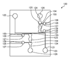
- FIG. 2 and FIG. 3A to FIG. 3C illustrate a configuration of microchannel chip 100 according to Embodiment 1 of the present invention.
- FIG. 2 is a plan view of microchannel chip 100 .
- FIG. 3A is a sectional view taken along line A-A of FIG. 2
- FIG. 3B is a sectional view taken along line B-B of FIG. 2
- FIG. 3C is a sectional view taken along line C-C of FIG. 2 .
- microchannel chip 100 includes first chip 110 having main channel part 140 and addition part 150 , and second chip 210 stacked on first chip 110 .
- First chip 110 includes first substrate 120 having partition walls 154 , 155 and 159 , and first film 130
- second chip 210 includes second substrate 230 having recesses 231 , 233 and 234 , and second film 250 .
- first chip 110 and second chip 210 are stacked in such a manner that first film 130 and second film 250 face the inner side (see FIG. 3A to FIG. 3C ).
- the surface of first film 130 is in close contact with the surface of second film 250 .
- partition walls 154 , 155 and 159 and recesses 231 , 233 and 234 are respectively disposed to face each other with first film 130 and second film 250 therebetween (see FIG. 3A to FIG. 3C ).
- First chip 110 is a chip in which fluid such as reagent and liquid sample flows.
- Deflective displaceable regions are formed at positions corresponding to partition walls 154 , 155 and 159 in first film 130 .
- the deflective displaceable regions function as diaphragm parts 131 , 133 and 134 (valve elements) of a micro valve for controlling the fluid flow in first chip 110 .
- Second chip 210 functions as an actuator of the micro valve.
- FIG. 4A to FIG. 5C illustrate a configuration of first chip 110 .
- FIG. 4A is a plan view of first chip 110
- FIG. 4B is a sectional view taken along line D-D of FIG. 4A .
- FIG. 5A is a sectional view taken along line E-E of FIG. 4A
- FIG. 5B is an enlarged view of a region surrounded by the broken line in FIG. 5A
- FIG. 5C is a plan view including the region surrounded by the broken line in FIG. 5A , in which all configurations of first substrate 120 and first film 130 to be stacked are illustrated with solid lines.
- First chip 110 is a chip for flowing of liquid.
- First chip 110 is composed of first substrate 120 and first film 130 .
- First chip 110 includes main channel part 140 and addition part 150 .
- Main channel part 140 is a channel for flowing of reagent and liquid sample (hereinafter referred to also as “reagent”).
- Main channel part 140 includes main flow path 141 , reagent inlet 142 and reagent outlet 143 .
- main flow path 141 is communicated with reagent inlet 142 for introducing reagent.
- the other end of main flow path 141 is communicated with reagent outlet 143 for ejecting reagent.
- the cross-sectional area and the cross-sectional shape of main flow path 141 are not limited.
- main channel 141 is a channel in which fluid can move by capillary action.
- main flow path 141 has a substantially rectangular cross-sectional shape with each side (width and depth) of about several tens of micrometers, for example.
- the “cross-section of the channel” means the cross-section of the channel orthogonal to the flow direction of the liquid (fluid).
- main flow path 141 reagent inlet 142 and reagent outlet 143 in first chip 110 are not limited.
- the reagent introduced from reagent inlet 142 flows to reagent outlet 143 through main flow path 141 .
- Addition part 150 adds test chemical liquid and the like to the reagent flowing through main flow path 141 , as necessary.
- the number and position of addition part 150 is not limited.
- addition part 150 is disposed on the upstream side and the downstream side (in total, two addition parts 150 are disposed) (see FIG. 4A ).
- Addition part 150 disposed on the upstream side of main flow path 141 , and that disposed on the downstream side of main flow path 141 have the same configuration. For such a configuration, addition part 150 disposed on the upstream side of main flow path 141 is described below.
- Addition part 150 includes liquid inlet 151 , first channel 152 , second channel 153 , a plurality of partition walls 154 and 155 , and a plurality of ejection parts 156 .
- First channel 152 and second channel 153 form a liquid channel
- First partition wall 154 is disposed between first channel 152 and second channel 153
- second partition wall 155 is disposed between second channel 153 and main flow path 141 .
- One end of first channel 152 is communicated with liquid inlet 151 .
- first partition wall 154 is disposed at the other end of first channel 152 .
- First partition wall 154 is disposed at one end of second channel 153 .
- second partition wall 155 is disposed at the other end of second channel 153 .
- First partition wall 154 and first film 130 communicate between first channel 152 and second channel 153 when the micro valve is in an open state.
- second partition wall 155 and first film 130 communicate between second channel 153 and main flow path 141 when the micro valve is in an open state.
- the liquid introduced from liquid inlet 151 flows through liquid channels (first channel 152 and second channel 153 ) and is then added to the reagent flowing in main flow path 141 .
- first channel 152 and second channel 153 are channels in which fluid can move by capillary action.
- first channel 152 and second channel 153 have a substantially rectangular cross-sectional shape with each side (width and depth) of about several tens of micrometers.
- the cross-sectional areas and the cross-sectional shapes of first channel 152 and second channel 153 may be identical to each other or may be different from each other. It is to be noted that, in the present embodiment, a downstream end part of first channel 152 , an intermediate part of second channel 153 , and a downstream end part of second channel 153 have a large cross-sectional area such that incoming liquid can be stored.
- First partition wall 154 and second partition wall 155 function as a valve seat of the micro valve.
- First partition wall 154 is disposed between first channel 152 and second channel 153 .
- second partition wall 155 is disposed between second channel 153 and main flow path 141 .
- the sizes and the shapes in a plan view of first partition wall 154 and second partition wall 155 are not limited as long as the function as the valve seat of the micro valve can be ensured.
- the sizes of first partition wall 154 and second partition wall 155 in the cross-sectional direction of the channel are respectively identical to those of the cross-sectional shapes of the downstream end part of first channel 152 and the downstream end part of second channel 153 .
- Ejection part 156 removes bubbles from first channel 152 and second channel 153 .
- One feature of microchannel chip 100 according to the present embodiment is the configuration of removing bubbles from first channel 152 and second channel 153 with ejection part 156 .
- the number of ejection part 156 is not limited.
- ejection part 156 is connected at the downstream end part of first channel 152 , and at the downstream end part of second channel 153 (see FIG. 4A ). It is to be noted that ejection part 156 connected at the downstream end part of first channel 152 and ejection part 156 connected at the downstream end part of second channel 153 have the same configuration. For such a configuration, ejection part 156 connected at the downstream end part of first channel 152 is described below.
- Ejection part 156 includes third channel 157 , fourth channel 158 and third partition wall 159 .
- Third channel 157 and fourth channel 158 form a discharge channel.
- Third partition wall 159 is disposed between third channel 157 and fourth channel 158 .
- One end of third channel 157 is communicated with a downstream end of first channel 152 .
- third partition wall 159 is disposed at the other end of third channel 157 .
- Third partition wall 159 is disposed at one end of fourth channel 158 .
- the other end of fourth channel 158 opens at a side surface (or to the outside) of first substrate 120 .
- Third partition wall 159 and first film 130 communicate between third channel 157 and fourth channel 158 when the micro valve is in an open state. When the liquid channel is filled with liquid, the bubbles in first channel 152 are pushed by the flow end of the liquid and discharged through the discharge channel (third channel 157 ).
- third channel 157 opens at first channel 152 between center O of first diaphragm part 131 and first partition wall 154 in flow direction X of liquid in first channel 152 (see, the arrow of FIG. 5C ).
- third channel 157 and fourth channel 158 are formed on a surface of first substrate 120 on first film 130 side.
- third channel 157 and fourth channel 158 are channels through which fluid can move by capillary action.
- third channel 157 and fourth channel 158 have a substantially rectangular cross-sectional shape with each side (width and depth) of about several tens of micrometers, for example.
- a downstream end part of third channel 157 is formed to have a large cross-sectional area, and can store incoming liquid.
- FIG. 6 is a bottom view of first substrate 120 .
- first substrate 120 is a substantially rectangular transparent resin substrate.
- the thickness of first substrate 120 is not limited.
- the thickness of first substrate 120 is, for example, 1 to 10 mm.
- the type of the resin of first substrate 120 is not limited, and may be appropriately selected from publicly known resins. Examples of the resin of first substrate 120 include polyethylene terephthalate, polycarbonate, polymethylmethacrylate, vinyl chloride, polypropylene, polyether, polyethylene, polystyrene, silicone resin, elastomer and the like.
- First substrate 120 includes main groove 121 , first through hole 122 , second through hole 123 , first groove 124 , second groove 125 , first partition wall 154 , second partition wall 155 , third through hole 126 , third groove 127 , fourth groove 128 and third partition wall 159 .
- main groove 121 is communicated with first through hole 122 .
- the other end of main groove 121 is communicated with second through hole 123 .
- first groove 124 is communicated with third through hole 126 .
- first partition wall 154 is disposed at the other end of first groove 124 .
- First partition wall 154 is disposed at one end of second groove 125 .
- second partition wall 155 is disposed at the other end of second groove 125 .
- third groove 127 is communicated with first groove 124 .
- third partition wall 159 is disposed at the other end of third groove 127 .
- Third partition wall 159 is disposed at one end of fourth groove 128 .
- the other end of fourth groove 128 opens at the side wall of first substrate 120 .
- FIG. 7A to FIG. 7C illustrate a configuration of first film 130 .
- FIG. 7A is a plan view of first film 130
- FIG. 7B is a sectional view taken along line F-F of FIG. 7A
- FIG. 7C is a sectional view taken along line G-G of FIG. 7A .
- First film 130 is a substantially rectangular transparent resin film. First film 130 is bonded on a surface of first substrate 120 on second chip 210 side. First film 130 includes a plurality of diaphragm parts each having a substantially spherical cap shape (first diaphragm part 131 , second diaphragm part 132 , third diaphragm part 133 , and fourth diaphragm part 134 ) (displaceable regions). Each of diaphragm parts 131 , 132 , 133 and 134 is disposed at a position corresponding to addition part 150 . To be more specific, first diaphragm part 131 is disposed at a position corresponding to first partition wall 154 in first film 130 .
- Second diaphragm part 132 is disposed at a position corresponding to a position between first partition wall 154 and second partition wall 155 in first film 130 .
- Third diaphragm part 133 is disposed at a position corresponding to second partition wall 155 in first film 130 .
- Fourth diaphragm part 134 is disposed at a position corresponding to third partition wall 159 in first film 130 .
- First film 130 functions as a valve element (diaphragm) of the micro valve having a diaphragm structure.
- first film 130 (first diaphragm part 131 , third diaphragm part 133 and fourth diaphragm part 134 ) is separated from first partition wall 154 , second partition wall 155 and third partition wall 159 .
- the type of the resin of first film 130 is not limited as long as first film 130 can function as a valve element (diaphragm), and may be appropriately selected from publicly known resins.
- the resin of first film 130 include polyethylene terephthalate, polycarbonate, polymethylmethacrylate, vinyl chloride, polypropylene, polyether, polyethylene, polystyrene, and silicone resin.
- first film 130 is not limited as long as first film 130 can function as a valve element (diaphragm), and may be appropriately set in accordance with the type (stiffness) of the resin.
- first film 130 has a thickness of about 20 ⁇ m.
- diaphragm parts 131 , 133 and 134 have sizes which can cover first partition wall 154 , second partition wall 155 and third partition wall 159 and can be housed in first recess 231 , third recess 233 and fourth recess 234 when first chip 110 and second chip 210 are stacked on each other.
- the external shape of first film 130 is appropriately designed such that a required function can be ensured.
- FIG. 8A and FIG. 8B illustrate a configuration of second chip 210 .
- FIG. 8A is a plan view of second chip 210
- FIG. 8B is a sectional view taken along line H-H of FIG. 8A .
- second chip 210 is composed of second substrate 230 and second film 250 .
- Second chip 210 includes a plurality of pressure chambers (first pressure chamber 211 , second pressure chamber 212 , third pressure chamber 213 and fourth pressure chamber 214 ) and a plurality of communication paths (first communication path 216 , second communication path 217 , third communication path 218 and fourth communication path 219 ).
- Second film 250 is bonded on one surface of second substrate 230 .
- First pressure chamber 211 is communicated with the outside of second substrate 230 through first communication path 216 .
- First pressure chamber 211 has a size which can house fifth diaphragm part 251 of second film 250 .
- Second pressure chamber 212 is communicated with the outside of second substrate 230 through second communication path 217 .
- Second pressure chamber 212 has a size which can house sixth diaphragm part 252 of second film 250 .
- Third pressure chamber 213 is communicated with the outside of second substrate 230 through third communication path 218 .
- Third pressure chamber 213 has a size which can house seventh diaphragm part 253 of second film 250 .
- Fourth pressure chamber 214 is communicated with the outside of second substrate 230 through fourth communication path 219 .
- Fourth pressure chamber 214 has a size which can house eighth diaphragm part 254 of second film 250 .
- first pressure chamber 211 , second pressure chamber 212 , third pressure chamber 213 and fourth pressure chamber 214 are not limited.
- each of first pressure chamber 211 , second pressure chamber 212 , third pressure chamber 213 and fourth pressure chamber 214 has a substantially columnar shape.
- the diameters and the depths of first pressure chamber 211 , second pressure chamber 212 , third pressure chamber 213 and fourth pressure chamber 214 are also not limited, and may be appropriately set.
- the diameters and the depths of first pressure chamber 211 , second pressure chamber 212 , third pressure chamber 213 and fourth pressure chamber 214 are identical to each other.
- first communication path 216 is communicated with first pressure chamber 211 .
- One end of second communication path 217 is communicated with second pressure chamber 212 .
- One end of third communication path 218 is communicated with third pressure chamber 213 .
- One end of fourth communication path 219 is communicated with fourth pressure chamber 214 .
- the other ends of communication paths 216 , 217 , 218 and 219 open at the side surface of second substrate 230 .
- the other ends of communication paths 216 , 217 , 218 and 219 may not open at the side surface of second substrate 230 .
- the other ends of communication paths 216 , 217 , 218 and 219 may open at the other surface of second substrate 230 (whose one surface is a surface on which second film 250 is bonded) through through holes respectively formed on second substrate 230 and communicated with the other ends of communication paths 216 , 217 , 218 and 219 .
- first communication path 216 , second communication path 217 , third communication path 218 and fourth communication path 219 are not limited.
- first communication path 216 , second communication path 217 , third communication path 218 and fourth communication path 219 are channels through which fluid can move.
- each of first communication path 216 , second communication path 217 , third communication path 218 and fourth communication path 219 has a substantially rectangular cross-sectional shape with each side (width and depth) of about several tens of micrometers, for example.
- first communication path 216 , second communication path 217 , third communication path 218 and fourth communication path 219 may be identical to each other or different from each other.
- the cross-sectional areas and the cross-sectional shapes of first communication path 216 , second communication path 217 , third communication path 218 and fourth communication path 219 are identical to each other.
- FIG. 9 is a plan view of second substrate 230 .
- second substrate 230 is a substantially rectangular transparent resin substrate.
- the size of second substrate 230 is not limited. In the present embodiment, second substrate 230 has a size equal to that of first substrate 120 .
- the thickness of second substrate 230 is not limited. The thickness of second substrate 230 is 1 to 10 mm, for example.
- the type of resin of second substrate 230 is not limited, and the resin of first substrate 120 may be used.
- Second substrate 230 includes first recess 231 , second recess 232 , third recess 233 , fourth recess 234 , first communication groove 236 , second communication groove 237 , third communication groove 238 and fourth communication groove 239 .
- First recess 231 is communicated with one end of first communication groove 236 .
- Second recess 232 is communicated with one end of second communication groove 237 .
- Third recess 233 is communicated with one end of third communication groove 238 .
- Fourth recess 234 is communicated with one end of fourth communication groove 239 .
- the shapes of first recess 231 , second recess 232 , third recess 233 and fourth recess 234 are not limited. In the present embodiment, each of first recess 231 , second recess 232 , third recess 233 and fourth recess 234 has a substantially columnar shape.
- first recess 231 , second recess 232 , third recess 233 and fourth recess 234 are also not limited. In the present embodiment, the diameters and the depths of first recess 231 , second recess 232 , third recess 233 and fourth recess 234 are identical to each other.
- first communication groove 236 is communicated with first recess 231 .
- second communication groove 237 is communicated with second recess 232 .
- third communication groove 238 is communicated with third recess 233 .
- fourth communication groove 239 is communicated with fourth recess 234 .
- the other ends of communication grooves 236 , 237 , 238 and 239 open at the side surface of second substrate 230 .
- the other ends of communication grooves 236 , 237 , 238 and 239 may not open at the side surface of second substrate 230 .
- the other ends of communication grooves 236 , 237 , 238 and 239 may open at the other of surface of second substrate 230 (whose one surface being a surface on which second film 250 is bonded) through through holes respectively formed on second substrate 230 and communicated with the other ends of communication grooves 236 , 237 , 238 and 239 .
- first recess 231 , second recess 232 , third recess 233 , fourth recess 234 , first communication groove 236 , second communication groove 237 , third communication groove 238 and fourth communication groove 239 are closed with second film 250 , first pressure chamber 211 , second pressure chamber 212 , third pressure chamber 213 , fourth pressure chamber 214 , first communication path 216 , second communication path 217 , third communication path 218 and fourth communication path 219 are formed.
- FIG. 10A to FIG. 10C illustrate a configuration of second film 250 .
- FIG. 10A is a plan view of second film 250
- FIG. 10B is a sectional view taken along line I-I of FIG. 10A
- FIG. 10C is a sectional view taken along line J-J of FIG. 10A .
- Second film 250 is a substantially rectangular transparent resin film. Second film 250 is bonded on a surface of second substrate 230 on first film 130 side. Second film 250 includes a plurality of diaphragm parts each having a substantially hemispherical shape (fifth diaphragm part 251 , sixth diaphragm part 252 , seventh diaphragm part 253 , eighth diaphragm part 254 ) (displaceable regions). Fifth diaphragm part 251 is disposed at a position corresponding to first recess 231 on second substrate 230 . Sixth diaphragm part 252 is disposed at a position corresponding to second recess 232 on second substrate 230 .
- Seventh diaphragm part 253 is disposed at a position corresponding to third recess 233 on second substrate 230 .
- Eighth diaphragm part 254 is disposed at a position corresponding to fourth recess 234 on second substrate 230 .
- second film 250 (fifth diaphragm part 251 , sixth diaphragm part 252 , seventh diaphragm part 253 and eighth diaphragm part 254 ) is put in recesses 231 , 232 , 233 and 234 .
- the type of the resin of second film 250 is not limited.
- the type of the resin of second film 250 may be appropriately selected from the resins for first film 130 .
- the thickness of second film 250 is not limited and is approximately equal to that of first film 130 .
- the external shape of second film 250 is appropriately designed so as ensure to a required function.
- the sizes of fifth diaphragm part 251 , sixth diaphragm part 252 , seventh diaphragm part 253 , eighth diaphragm part 254 are respectively smaller than the sizes of recesses 231 , 232 , 233 and 234 .
- first chip 110 is produced by joining first film 130 on first substrate 120 by thermo compression bonding. At this time, diaphragm parts 131 , 132 , 133 and 134 of the joined first film 130 are disposed to protrude from one surface of first substrate 120 (see FIG. 5A and FIG. 5B ).
- second chip 210 is produced by joining second film 250 on second substrate 230 by thermo compression bonding. At this time, diaphragm parts 251 , 252 , 253 and 254 of the joined second film 250 are disposed to be put into respective recesses 231 , 232 , 233 and 234 from one surface of second substrate 230 (see FIG. 8B ).
- first chip 110 and second chip 210 are stacked on each other with first film 130 and second film 250 therebetween such that partition walls 154 , 155 and 159 and pressure chambers 211 , 213 and 214 respectively face each other.
- diaphragm parts 131 , 132 , 133 and 134 of first film 130 respectively overlap diaphragm parts 251 , 252 , 253 and 254 of second film 250 (see FIG. 3A to FIG. 3C ).
- gaps are formed between diaphragm parts 131 , 132 , 133 and 134 and partition walls 154 , 155 and 159 and the liquid channel is opened (valve opening state). In this manner, microchannel chip 100 is produced.
- FIG. 11A to FIG. 11D are enlarged views of a region around first channel 152 for describing a usage of microchannel chip 100 . It is to be noted that FIG. 11A to FIG. 11D illustrate only first channel 152 , second channel 153 , third channel 157 and first diaphragm part 131 .
- first chip 110 and second chip 210 are separated from each other to allow liquid to pass through main flow path 141 of first chip 110 .
- fluid such as reagent and liquid sample is provided to reagent inlet 142 .
- the fluid flows from reagent inlet 142 to reagent outlet 143 through main flow path 141 .
- liquid is allowed to pass through the liquid channel of first chip 110 .
- liquid such as liquid sample is provided to liquid inlet 151 .
- the liquid flows through first channel 152 from liquid inlet 151 toward second channel 153 .
- first channel 152 When the liquid is sent to an end portion of first channel 152 , the liquid first advances through an outer periphery portion of first channel 152 where capillarity easily occurs (see FIG. 11A ). Then, at the end portion of first channel 152 , the liquid further advances in such a manner as to turn around along the outer periphery portion of first channel 152 where capillarity easily occurs liquid before the center portion is filled with the liquid, (see FIG. 11B and FIG. 11C ).
- fourth pressure chamber 214 is not increased, and a gap is formed between first film 130 (fourth diaphragm part 134 ) and third partition wall 159 and a discharge channel is opened (valve opening state).
- the bubbles remaining in first channel 152 without being pushed to second channel 153 side are pushed to the discharge channel.
- fourth diaphragm part 134 protruding toward the inside of fourth pressure chamber 214 is pushed.
- the shape of fourth diaphragm part 134 is changed, and fourth diaphragm part 134 is pushed toward third partition wall 159 .
- timing of increasing the pressure in fourth pressure chamber 214 may be a timing when the liquid filling first channel 152 described later is sent to second channel 153 , or other timings as long as the timing is after the bubbles are removed from the inside of first channel 152 .
- Fourth diaphragm part 134 pushed out from fourth pressure chamber 214 in the above-mentioned manner makes contact with third partition wall 159 , and the discharge channel is closed (valve closing state). Thus, the flow of the liquid through the discharge channel is prohibited. Accordingly, the flow of the liquid is stopped. In this manner, it is possible to fill first channel 152 with the liquid without allowing the bubbles to remain in first channel 152 .
- first channel 152 when the liquid filling first channel 152 is sent to second channel 153 , the pressure in fourth pressure chamber 214 disposed on the downstream side of second channel 153 is released, for example. As a result, the liquid in first channel 152 flows into second channel 153 . The liquid reaching an end portion of second channel 153 first advances through the outer periphery portion of second channel 153 where capillarity easily occurs. Then, at the end portion of second channel 153 , the liquid further advances in such a manner as to turn around along the outer periphery portion of second channel 153 where capillarity easily occurs before the center portion is filled with the liquid.
- fourth pressure chamber 214 which acts on second channel 153 is not increased, and a gap is formed between first film 130 (fourth diaphragm part 134 ) and third partition wall 159 (valve opening state).
- the bubbles remaining in second channel 153 without being pushed to main flow path 141 side are pushed to the discharge channel.
- the gap between fourth diaphragm part 134 and third partition wall 159 is closed (valve closing state).
- the flow of the liquid through the discharge channel is prohibited. Accordingly, the flow of the liquid is stopped.
- the timing of increasing the pressure in fourth pressure chamber 214 of second channel 153 side may be a timing when the liquid filling second channel 153 described later is sent to main flow path 141 , or other timings as long as the timing is after the bubbles are removed from the inside of second channel 153 .
- the pressure in second pressure chamber 212 is increased with the pressure in first pressure chamber 211 increased, and the pressure in third pressure chamber 213 is released. In this manner, a certain amount of liquid can be sent into main flow path 141 from second channel 153 .
- the pressure in first pressure chamber 211 and the pressure in second pressure chamber 212 are released with the pressure in third pressure chamber 213 increased. In this manner, the liquid again flows into second channel 153 from first channel 152 , and second channel 153 is filled with the liquid.
- filling of first channel 152 and second channel 153 with the liquid, flowing of liquid from second channel 153 to main flow path 141 , and stopping of flow of liquid from second channel 153 to main flow path 141 can be performed at any timing. For example, it is possible to cause a reaction between a reagent flowing through main flow path 141 and another reagent after a reaction between a reagent and a specific reagent is caused for a certain period in reagent inlet 142 .
- first channel 152 and second channel 153 are sent to the discharge channel, and thus first channel 152 and second channel 153 can be surely filled with liquid without allowing the bubbles to remain in first channel 152 or second channel 153 .
- first groove 124 and third groove 127 may be chamfered (see, the region surrounded with solid line in FIG. 12A ).
- the liquid reaching the position from point P 2 side does not flow into third channel 157 .
- the liquid further advances in such a manner as to turn around along the outer periphery portion on P 1 side where the distance between first film 130 and the bottom surface of first groove 124 is small. Accordingly, the effect of removal of bubbles is facilitated.
- Microchannel chip 300 according to a modification of Embodiment 2 differs from ejection part 156 of microchannel chip 100 according to Embodiment 1 in that first channel 152 is communicated with two discharge channels.
- components same as those of microchannel chip 100 according to Embodiment 1 are denoted with the same reference numerals and description thereof is omitted, and, only components of microchannel chip 300 different from those of microchannel chip 100 are described.
- FIG. 13A to FIG. 13C illustrate a configuration of ejection part 356 of microchannel chip 300 according to the modification of Embodiment 1.
- FIG. 13A is a plan view of a region around ejection part 356 in microchannel chip 300
- FIG. 13B is a sectional view taken along line K-K of FIG. 13A
- FIG. 13C is a sectional view taken along line L-L of FIG. 13A .
- microchannel chip 300 includes first chip 310 including first substrate 320 and first film 330 , and second chip 410 including second substrate 430 and second film 450 .
- First chip 310 includes main channel part 140 and addition part 350 .
- addition part 350 includes liquid inlet 151 , first channel 152 , second channel 153 , a plurality of partition walls 154 , 155 and a plurality of ejection parts 356 .
- Ejection part 356 includes fifth channel 351 , sixth channel 352 and fourth partition wall 353 in addition to third channel 157 , fourth channel 158 , and third partition wall 159 .
- the discharge channel having third channel 157 , fourth channel 158 , fifth channel 351 and sixth channel 352 is continuously connected with a micro valve (valve) for opening and closing between the inside and outside of first channel 152 .
- third channel 157 is communicated with first channel 152 , and the downstream side thereof is branched.
- Third partition wall 159 is disposed at one of the branched ends on the downstream side.
- the upstream end of fifth channel 351 opens at a position which is plane symmetrical with the upstream end of third channel 157 .
- the upstream end of fifth channel 351 is communicated with first channel 152 .
- the downstream end of fifth channel 351 is communicated with third channel 157 .
- Sixth channel 352 is disposed so as to adjacent to fifth channel 351 with fourth partition wall 353 therebetween.
- the other end of sixth channel 352 opens at a side surface of first substrate 320 .
- the other end of sixth channel 352 may open to the outside through a through hole formed to communicate with the other end of sixth channel 352 on first substrate 320 .
- First substrate 320 includes fifth groove 354 , sixth groove 355 and fourth partition wall 353 in addition to main groove 121 , through holes 122 , 123 and 126 , grooves 124 , 125 , 127 and 128 , and partition walls 154 , 155 and 159 .
- fifth groove 354 and sixth groove 355 are closed with first film 330 , fifth channel 351 and sixth channel 352 are formed (see FIG. 13B and FIG. 13C ).
- First film 330 includes ninth diaphragm part 331 having a substantially spherical cap shape in addition to diaphragm parts 131 , 132 , 133 and 134 .
- Ninth diaphragm part 331 is disposed at a position corresponding to fourth partition wall 353 in first film 330 .
- Second chip 410 is composed of second substrate 430 and second film 450 .
- Second chip 410 includes fifth pressure chamber 411 and fifth communication path 412 in addition to pressure chambers 211 , 212 , 213 and 214 , and communication paths 216 , 217 , 218 and 219 .
- One end of fifth communication path 412 is communicated with fifth pressure chamber 411 .
- the other end of fifth communication path 412 opens at a side surface of second substrate 430 .
- Second substrate 430 includes fifth recess 413 and fifth communication groove 414 in addition to recesses 231 , 232 , 233 and 234 and communication grooves 236 , 237 , 238 and 239 .
- Fifth recess 413 is communicated with one end of fifth communication groove 414 .
- fifth communication path 412 and fifth pressure chamber 411 are formed (see FIG. 13B and FIG. 13C ).
- Second film 450 includes tenth diaphragm part 451 having a substantially spherical cap shape in addition to diaphragm parts 251 , 252 , 253 and 254 .
- Tenth diaphragm part 451 is disposed at a position corresponding to fourth partition wall 353 .
- tenth diaphragm part 451 has a size smaller than the size of fifth recess 413 . In the state where second film 450 is bonded on second substrate 430 , second film 450 is separated from fourth partition wall 353 .
- FIG. 14A to FIG. 14D are enlarged views of a region around first channel 152 for describing usage of microchannel chip 300 . It is to be noted that in FIG. 14A to FIG. 14D illustrate only first channel 152 , second channel 153 , third channel 157 , first diaphragm part 131 and fifth channel 351 .
- the liquid When the liquid is sent to the end portion of first channel 152 after the liquid is supplied to main flow path 141 of first chip 310 , the liquid first advances through the outer periphery portion of first channel 152 where capillarity easily occurs (see FIG. 14A ). Then, the liquid reaching fifth channel 351 flows through fifth channel 351 and, before the center portion is filled with the liquid, the liquid further advances in such a manner as to turn around along the outer periphery portion of first channel 152 where capillarity easily occurs (see FIG. 14B and FIG. 14C ).
- fourth pressure chamber 214 is increased to press first film 330 (fourth diaphragm part 134 ) against third partition wall 159 (valve close state). Meanwhile, the pressure in fifth pressure chamber 411 is not increased, and a gap is formed between first film 330 (ninth diaphragm part 331 ) and fourth partition wall 353 (valve opening state). In this manner, bubbles can be removed from both of third channel 157 and fifth channel 351 .
- fifth pressure chamber 411 is increased to press first film 330 (ninth diaphragm part 331 ) against fourth partition wall 353 (valve close state).
- first film 330 nearth diaphragm part 331
- fourth partition wall 353 valve opening state
- channels 157 and 351 are connected to the both side walls of the end portion of first channel 152 , bubbles can be surely removed from the liquid channels even when the liquid first reaches third channel 157 and when the liquid first reaches fifth channel 351 at the end portion of first channel 152 .
- Microchannel chip 500 according to Embodiment 2 differs from ejection part 156 according to Embodiment 1 in that discharge hole 557 is provided in place of the discharge channel.
- the component same as those of microchannel chip 100 according to Embodiment 1 are denoted with the same reference numerals and descriptions thereof are omitted, and, components of microchannel chip 500 different from those of microchannel chip 100 are mainly described below.
- FIG. 15A and FIG. 15B illustrate a configuration of ejection part 556 of microchannel chip 500 according to Embodiment 2.
- FIG. 15A is a plan view of a region around first channel 152
- FIG. 15B is a sectional view taken along line O-O of FIG. 15A .
- microchannel chip 500 includes first chip 510 having first substrate 520 and first film 530 , and second chip 610 having second substrate 630 and second film 650 .
- First chip 510 includes first substrate 520 , first film 530 , main channel part 140 and ejection part 556 .
- Ejection part 556 removes bubbles from first channel 152 and second channel 153 .
- the number of ejection part 556 is not limited.
- ejection part 556 is connected with the downstream end part of first channel 152 , and with the downstream end part of second channel 153 . It is to be noted that the downstream end part of first channel 152 connected with ejection part 556 , and the downstream end part of second channel 153 connected with ejection part 556 have the configuration. For such a configuration, the downstream end part of first channel 152 connected with ejection part 556 is described below.
- Ejection part 556 includes discharge hole 557 and an opening/closing jig.
- the shape of discharge hole 557 is not limited.
- the shape of discharge hole 557 may be a columnar shape or a rectangular prism shape.
- discharge hole 557 has a columnar shape.
- One opening part of discharge hole 557 is disposed at the bottom surface of first groove 124 , and the other opening part is disposed at the side surface or the rear surface of first substrate 520 .
- one opening part of discharge hole 557 is disposed between the center of first diaphragm part 131 and first partition wall 154 in a direction of liquid flow in first channel 152 .
- the position of discharge hole 557 in the width direction of first channel 152 is not limited.
- the position of discharge hole 557 in the width direction of first channel 152 may be a center portion of the bottom surface of the first groove, or a region of the side surface side (end portion) of first groove 124 .
- discharge hole 557 is disposed in a region on the side surface side relative to the center of the first groove 124 on the bottom surface of first groove 124 .
- the cross-sectional area and the cross-sectional shape of discharge hole 557 are not limited as long as bubbles can move.
- the opening/closing jig opens and closes discharge hole 557 opening at the side surface or the bottom surface of second substrate 630 .
- the opening/closing jig is disposed on the side of a surface (rear surface) opposite to the surface on which first chip 510 is disposed.
- FIG. 16A to FIG. 16D are plan views of a region around first channel 152 for describing a usage of microchannel chip 500 . It is to be noted that FIG. 16A to FIG. 16D illustrate only first channel 152 , second channel 153 , first diaphragm part 131 and discharge hole 557 .
- first channel 152 When liquid is sent to the end portion of first channel 152 after the liquid is supplied to flow through main flow path 141 of first chip 510 , the liquid first advances through the outer periphery portion of first channel 152 where capillarity easily occurs (see FIG. 16A ). Then, before the center portion is filled with the liquid, the liquid further advances in such a manner as to turn around along the outer periphery portion of first channel 152 where capillarity easily occurs (see FIG. 16B and FIG. 16C ).
- the opening/closing jig opens the opening part of discharge hole 557 .
- the bubbles remaining in first channel 152 without being pushed to second channel 153 side are pushed to the outside through discharge hole 557 .
- the opening part formed on the bottom surface of first substrate 520 is closed with the opening/closing jig. In this manner, it is possible to fill first channel 152 with the liquid.
- discharge hole 557 is formed on the bottom surface of first channel 152 , bubbles can be surely removed from first channel 152 .
- a gap may be formed between the diaphragm part and the partition wall, thus opening the liquid channel.
- the second film is formed in a planar shape.
- the pressure in the recess becomes a negative pressure
- the second film covering the recess is sucked into the recess, and the diaphragm part bends toward the recess.
- a gap is formed between the first film and the partition wall and the liquid channel is opened.
- the pressure in the recess is released, the shape of the diaphragm part sucked into the recess is returned to the original shape, and the diaphragm part and the partition wall make contact with each other, thus closing the liquid channel.
- fourth diaphragm part 134 and third partition wall 159 and tenth diaphragm part 451 and fourth partition wall 353 may make contact with each other to close the discharge channel (valve).
- the second film is formed in a planar shape.
- the fluid handling device of the embodiments of the present invention is useful for a microchannel chip which is used in the scientific field, medical field, and the like, for example.
Applications Claiming Priority (3)
| Application Number | Priority Date | Filing Date | Title |
|---|---|---|---|
| JP2014-023510 | 2014-02-10 | ||
| JP2014023510A JP6506907B2 (ja) | 2014-02-10 | 2014-02-10 | 液体取扱装置 |
| PCT/JP2015/053650 WO2015119290A1 (ja) | 2014-02-10 | 2015-02-10 | 液体取扱装置 |
Publications (2)
| Publication Number | Publication Date |
|---|---|
| US20170173583A1 US20170173583A1 (en) | 2017-06-22 |
| US10029255B2 true US10029255B2 (en) | 2018-07-24 |
Family
ID=53778087
Family Applications (1)
| Application Number | Title | Priority Date | Filing Date |
|---|---|---|---|
| US15/117,030 Active US10029255B2 (en) | 2014-02-10 | 2015-02-10 | Liquid handling device |
Country Status (4)
| Country | Link |
|---|---|
| US (1) | US10029255B2 (ja) |
| EP (1) | EP3106879A4 (ja) |
| JP (1) | JP6506907B2 (ja) |
| WO (1) | WO2015119290A1 (ja) |
Cited By (2)
| Publication number | Priority date | Publication date | Assignee | Title |
|---|---|---|---|---|
| US20180015469A1 (en) * | 2016-07-13 | 2018-01-18 | STRATEC CONSUMABLES GmbH | Microfluidic flow control and device |
| US11311880B2 (en) | 2017-03-28 | 2022-04-26 | Nec Corporation | Microchip controlling system |
Families Citing this family (3)
| Publication number | Priority date | Publication date | Assignee | Title |
|---|---|---|---|---|
| GB201615452D0 (en) | 2016-09-12 | 2016-10-26 | Fluidic Analytics Ltd | Improvements in or relating to valves for microfluidics devices |
| KR102022202B1 (ko) * | 2018-12-10 | 2019-09-18 | 한국기계연구원 | 기포 배출 미세유체소자 |
| JP2020138283A (ja) * | 2019-02-28 | 2020-09-03 | 株式会社エンプラス | 流体取扱装置の製造方法 |
Citations (12)
| Publication number | Priority date | Publication date | Assignee | Title |
|---|---|---|---|---|
| JP2001304440A (ja) | 2000-04-27 | 2001-10-31 | Natl Inst Of Advanced Industrial Science & Technology Meti | マイクロバルブ装置及びその製作方法 |
| US6406605B1 (en) | 1999-06-01 | 2002-06-18 | Ysi Incorporated | Electroosmotic flow controlled microfluidic devices |
| JP2002228033A (ja) | 2001-02-05 | 2002-08-14 | Olympus Optical Co Ltd | 分離型マイクロバルブ |
| JP2004033919A (ja) | 2002-07-03 | 2004-02-05 | Inst Of Physical & Chemical Res | マイクロ流体制御機構およびマイクロチップ |
| US20040209354A1 (en) | 2002-12-30 | 2004-10-21 | The Regents Of The University Of California | Fluid control structures in microfluidic devices |
| JP2005337415A (ja) | 2004-05-28 | 2005-12-08 | Aida Eng Ltd | マイクロバルブ、マイクロポンプ及びこれらを内蔵するマイクロチップ |
| US20070053796A1 (en) | 2005-09-02 | 2007-03-08 | Jen-Jr Gau | Cartridge having variable volume reservoirs |
| JP2009510337A (ja) | 2005-10-03 | 2009-03-12 | キオニックス インコーポレイテッド | マイクロ流体ポンプおよびバルブ構造体ならびにその製造方法 |
| JP2010230529A (ja) | 2009-03-27 | 2010-10-14 | Univ Of Tsukuba | 自動溶液注入デバイス |
| JP2011030522A (ja) | 2009-08-04 | 2011-02-17 | Aida Engineering Ltd | マイクロ流体デバイス |
| US20120128549A1 (en) | 2006-01-19 | 2012-05-24 | Rheonix, Inc. | Microfluidic systems and control methods |
| WO2013014905A1 (ja) | 2011-07-25 | 2013-01-31 | 株式会社エンプラス | 流体取扱装置および流体取扱方法 |
Family Cites Families (1)
| Publication number | Priority date | Publication date | Assignee | Title |
|---|---|---|---|---|
| EP1946830B1 (en) * | 2005-11-07 | 2019-04-03 | Konica Minolta Medical & Graphic, Inc. | Microreactor |
-
2014
- 2014-02-10 JP JP2014023510A patent/JP6506907B2/ja not_active Expired - Fee Related
-
2015
- 2015-02-10 EP EP15745813.4A patent/EP3106879A4/en not_active Withdrawn
- 2015-02-10 WO PCT/JP2015/053650 patent/WO2015119290A1/ja active Application Filing
- 2015-02-10 US US15/117,030 patent/US10029255B2/en active Active
Patent Citations (13)
| Publication number | Priority date | Publication date | Assignee | Title |
|---|---|---|---|---|
| US6406605B1 (en) | 1999-06-01 | 2002-06-18 | Ysi Incorporated | Electroosmotic flow controlled microfluidic devices |
| JP2001304440A (ja) | 2000-04-27 | 2001-10-31 | Natl Inst Of Advanced Industrial Science & Technology Meti | マイクロバルブ装置及びその製作方法 |
| JP2002228033A (ja) | 2001-02-05 | 2002-08-14 | Olympus Optical Co Ltd | 分離型マイクロバルブ |
| JP2004033919A (ja) | 2002-07-03 | 2004-02-05 | Inst Of Physical & Chemical Res | マイクロ流体制御機構およびマイクロチップ |
| US20040209354A1 (en) | 2002-12-30 | 2004-10-21 | The Regents Of The University Of California | Fluid control structures in microfluidic devices |
| JP2005337415A (ja) | 2004-05-28 | 2005-12-08 | Aida Eng Ltd | マイクロバルブ、マイクロポンプ及びこれらを内蔵するマイクロチップ |
| US20070053796A1 (en) | 2005-09-02 | 2007-03-08 | Jen-Jr Gau | Cartridge having variable volume reservoirs |
| JP2009510337A (ja) | 2005-10-03 | 2009-03-12 | キオニックス インコーポレイテッド | マイクロ流体ポンプおよびバルブ構造体ならびにその製造方法 |
| US20120128549A1 (en) | 2006-01-19 | 2012-05-24 | Rheonix, Inc. | Microfluidic systems and control methods |
| JP2010230529A (ja) | 2009-03-27 | 2010-10-14 | Univ Of Tsukuba | 自動溶液注入デバイス |
| JP2011030522A (ja) | 2009-08-04 | 2011-02-17 | Aida Engineering Ltd | マイクロ流体デバイス |
| WO2013014905A1 (ja) | 2011-07-25 | 2013-01-31 | 株式会社エンプラス | 流体取扱装置および流体取扱方法 |
| JP2013047672A (ja) * | 2011-07-25 | 2013-03-07 | Enplas Corp | 流体取扱装置および流体取扱方法 |
Non-Patent Citations (2)
| Title |
|---|
| Extended European Search Report for 15745813.4 dated Aug. 14, 2017. |
| International Search Report from International Application No. PCT/JP2015/053650 dated Mar. 10, 2015. |
Cited By (3)
| Publication number | Priority date | Publication date | Assignee | Title |
|---|---|---|---|---|
| US20180015469A1 (en) * | 2016-07-13 | 2018-01-18 | STRATEC CONSUMABLES GmbH | Microfluidic flow control and device |
| US10888861B2 (en) * | 2016-07-13 | 2021-01-12 | STRATEC Consumables Gmb | Microfluidic flow control and device |
| US11311880B2 (en) | 2017-03-28 | 2022-04-26 | Nec Corporation | Microchip controlling system |
Also Published As
| Publication number | Publication date |
|---|---|
| WO2015119290A1 (ja) | 2015-08-13 |
| JP6506907B2 (ja) | 2019-04-24 |
| JP2015152317A (ja) | 2015-08-24 |
| EP3106879A1 (en) | 2016-12-21 |
| US20170173583A1 (en) | 2017-06-22 |
| EP3106879A4 (en) | 2017-09-13 |
Similar Documents
| Publication | Publication Date | Title |
|---|---|---|
| US10029255B2 (en) | Liquid handling device | |
| US9463459B2 (en) | Fluid handling device and method of handling fluid | |
| KR101984699B1 (ko) | 핵산 분석용 미세 유체 시스템 | |
| JP6111161B2 (ja) | 流体取扱装置および流体取扱方法 | |
| US9987630B2 (en) | Fluid handling device and method of using the same | |
| US11712695B2 (en) | Fluid handling device and fluid handling system | |
| US20210299652A1 (en) | Liquid handling device and liquid handling method | |
| US20210283602A1 (en) | Liquid handling device and liquid handling method | |
| JP6357217B2 (ja) | 流体取扱装置および流体取扱方法 | |
| US20210283604A1 (en) | Liquid handling device and liquid handling method | |
| US10458572B2 (en) | Liquid handling device | |
| US11566727B2 (en) | Fluid handling device and manufacturing method of fluid handling device | |
| US11738348B2 (en) | Fluid handling device | |
| US20200024123A1 (en) | Liquid handling apparatus | |
| WO2020178947A1 (en) | Fluid handling device | |
| JP7201402B2 (ja) | 検査チップ | |
| WO2020178951A1 (en) | Fluid handling device | |
| JP2022045741A (ja) | 液体取扱装置 | |
| JP2022049409A (ja) | 液体取扱装置 |
Legal Events
| Date | Code | Title | Description |
|---|---|---|---|
| AS | Assignment |
Owner name: ENPLAS CORPORATION, JAPAN Free format text: ASSIGNMENT OF ASSIGNORS INTEREST;ASSIGNOR:KITAMOTO, KEN;REEL/FRAME:039355/0780 Effective date: 20160601 |
|
| STCF | Information on status: patent grant |
Free format text: PATENTED CASE |
|
| MAFP | Maintenance fee payment |
Free format text: PAYMENT OF MAINTENANCE FEE, 4TH YEAR, LARGE ENTITY (ORIGINAL EVENT CODE: M1551); ENTITY STATUS OF PATENT OWNER: LARGE ENTITY Year of fee payment: 4 |