US10024896B2 - Inverter-driven rotary electric machine, phase-to-phase insulation partial discharge inspection method and phase-to-phase insulation partial discharge inspection apparatus - Google Patents
Inverter-driven rotary electric machine, phase-to-phase insulation partial discharge inspection method and phase-to-phase insulation partial discharge inspection apparatus Download PDFInfo
- Publication number
- US10024896B2 US10024896B2 US14/112,828 US201114112828A US10024896B2 US 10024896 B2 US10024896 B2 US 10024896B2 US 201114112828 A US201114112828 A US 201114112828A US 10024896 B2 US10024896 B2 US 10024896B2
- Authority
- US
- United States
- Prior art keywords
- voltage
- phase
- partial discharge
- electric machine
- rotary electric
- Prior art date
- Legal status (The legal status is an assumption and is not a legal conclusion. Google has not performed a legal analysis and makes no representation as to the accuracy of the status listed.)
- Active, expires
Links
Images


Classifications
-
- G—PHYSICS
- G01—MEASURING; TESTING
- G01R—MEASURING ELECTRIC VARIABLES; MEASURING MAGNETIC VARIABLES
- G01R25/00—Arrangements for measuring phase angle between a voltage and a current or between voltages or currents
-
- G—PHYSICS
- G01—MEASURING; TESTING
- G01R—MEASURING ELECTRIC VARIABLES; MEASURING MAGNETIC VARIABLES
- G01R31/00—Arrangements for testing electric properties; Arrangements for locating electric faults; Arrangements for electrical testing characterised by what is being tested not provided for elsewhere
- G01R31/12—Testing dielectric strength or breakdown voltage ; Testing or monitoring effectiveness or level of insulation, e.g. of a cable or of an apparatus, for example using partial discharge measurements; Electrostatic testing
- G01R31/1227—Testing dielectric strength or breakdown voltage ; Testing or monitoring effectiveness or level of insulation, e.g. of a cable or of an apparatus, for example using partial discharge measurements; Electrostatic testing of components, parts or materials
- G01R31/1263—Testing dielectric strength or breakdown voltage ; Testing or monitoring effectiveness or level of insulation, e.g. of a cable or of an apparatus, for example using partial discharge measurements; Electrostatic testing of components, parts or materials of solid or fluid materials, e.g. insulation films, bulk material; of semiconductors or LV electronic components or parts; of cable, line or wire insulation
- G01R31/1272—Testing dielectric strength or breakdown voltage ; Testing or monitoring effectiveness or level of insulation, e.g. of a cable or of an apparatus, for example using partial discharge measurements; Electrostatic testing of components, parts or materials of solid or fluid materials, e.g. insulation films, bulk material; of semiconductors or LV electronic components or parts; of cable, line or wire insulation of cable, line or wire insulation, e.g. using partial discharge measurements
-
- G—PHYSICS
- G01—MEASURING; TESTING
- G01R—MEASURING ELECTRIC VARIABLES; MEASURING MAGNETIC VARIABLES
- G01R31/00—Arrangements for testing electric properties; Arrangements for locating electric faults; Arrangements for electrical testing characterised by what is being tested not provided for elsewhere
- G01R31/34—Testing dynamo-electric machines
- G01R31/346—Testing of armature or field windings
-
- H—ELECTRICITY
- H02—GENERATION; CONVERSION OR DISTRIBUTION OF ELECTRIC POWER
- H02K—DYNAMO-ELECTRIC MACHINES
- H02K3/00—Details of windings
-
- G—PHYSICS
- G01—MEASURING; TESTING
- G01R—MEASURING ELECTRIC VARIABLES; MEASURING MAGNETIC VARIABLES
- G01R31/00—Arrangements for testing electric properties; Arrangements for locating electric faults; Arrangements for electrical testing characterised by what is being tested not provided for elsewhere
- G01R31/34—Testing dynamo-electric machines
- G01R31/343—Testing dynamo-electric machines in operation
Definitions
- the present invention relates to a rotary electric machine driven by an inverter (specifically an inverter-driven rotary electric machine having a rated voltage of 700 Vrms or less), and a phase-to-phase insulation partial discharge inspection method and a phase-to-phase insulation partial discharge inspection apparatus for the rotary electric machine.
- an inverter specifically an inverter-driven rotary electric machine having a rated voltage of 700 Vrms or less
- a phase-to-phase insulation partial discharge inspection method and a phase-to-phase insulation partial discharge inspection apparatus for the rotary electric machine specifically an inverter-driven rotary electric machine having a rated voltage of 700 Vrms or less
- Non-Patent Document 1 it has been reported that, if a steep voltage (inverter surge voltage) generated when a switching element inside an inverter turns ON/OFF propagates along a cable and reaches a terminal of the rotary electric machine, then mismatching takes place in surge impedance between the cable and the rotary electric machine, as a result of which the voltage across the terminal of the rotary electric machine jumps to a magnitude of twice an output voltage of the inverter.
- organic insulating materials are generally used in a low-voltage rotary electric machine having a voltage of 700 Vrms or less. Since such organic insulating materials are poor in resistance to partial discharge (PD), there is the possibility that, if the rotary electric machine is used in a condition under which partial discharge will occur, dielectric breakdown may occur in a comparatively short period of time. Therefore, such an insulation design as permits partial discharge not to occur during operation is conventionally adopted for low-voltage rotary electric machines having a voltage of 700 Vrms or less.
- PD partial discharge
- the rotary electric machine is insulated in such designs that insulation parts between winding turns, between phases of the rotary electric machine and between the rotary electric machine and the ground have an increased insulation thickness so that partial discharge inception voltages (PDIV) across the insulation parts are higher than voltages applied to the insulation parts of the rotary electric machine upon operation to thereby prevent such partial discharge.
- PDIV partial discharge inception voltages
- a sine wave voltage or an impulse voltage is applied to the rotary electric machine to ensure that no partial discharge occurs at any of the insulation parts between the winding turns, between the phases and between the rotary electric machine and the ground.
- Non-Patent Document 2 discloses such an insulation design and inspection method as just described.
- Patent Document 1 discloses a partial discharge measurement method to be used in this instance, for example.
- Non-Patent Document 1 Technical Report of the Institute of Electrical Engineers of Japan, No. 739, p.12 to 20
- Non-Patent Document 2 IEC60034-18-41
- an inverter-driven rotary electric machine In the machine, a surge propagation time period ⁇ coil of one coil and a partial discharge inception voltage PDIV between winding turns of a rotary electric machine winding are set such that partial discharge does not occur even if an impulse voltage having a voltage rise time period tr and a voltage peak V max which satisfy an expression (A1) given below is applied: tr >( ⁇ coil ⁇ V max )/(PDIV) (A1)
- the impulse voltage is an oscillation voltage having an oscillation frequency f
- the voltage rise time period tr is set so as to satisfy the following expression (A2): tr ⁇ 1/(4 f ) (A2)
- the impulse voltage is an oscillation voltage having an oscillation frequency f
- the voltage rise time period tr is set so as to satisfy the following expression (A2): tr ⁇ 1/(4 f ) (A2)
- the impulse voltage is a damped oscillation voltage having the oscillation frequency f and a time constant K
- the oscillation frequency f is set so as to satisfy the following expression (A3): ⁇ 1/(2 K ⁇ ln (( V test /V max ) ⁇ 1) ⁇ f ⁇ 1/(2 ⁇ ( L ⁇ C )) (A3)
- a phase-to-phase insulation partial discharge inspection apparatus includes: an impulse power supply configured to apply an impulse voltage having a voltage rise time period tr which satisfies an expression (A1) given below to the rotary electric machine; a measurement section configured to measure partial discharge which occurs when the impulse voltage is applied to the rotary electric machine; and a decision section configured to determine that, when partial discharge is not measured by the measurement section, a phase-to-phase insulation performance is acceptable.
- the impulse voltage is a damped oscillation voltage having the oscillation frequency f and a time constant K
- the oscillation frequency f is set so as to satisfy the following expression (A3): ⁇ 1/(2 K ⁇ ln (( V test /V max ) ⁇ 1) ⁇ f ⁇ 1/(2 ⁇ ( L ⁇ C )) (A3)
- an inverter-driven rotary electric machine which has an appropriate insulation performance and permits occurrence of partial discharge can be provided.
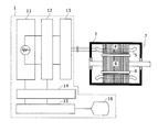
- FIG. 2 is a view showing an example of an inspection circuit upon inspection of phase-to-phase insulation of a motor.
- FIG. 3 is a view illustrating an applied voltage waveform upon inspection of phase-to-phase insulation.
- FIG. 4 is a view illustrating a variation of a winding turn-to-turn shared voltage V coil with respect to an impulse voltage rise time period tr.
- FIG. 5 is a view illustrating a testing voltage V max necessary condition in accordance with which partial discharge (PD) does not occur between winding turns.
- FIG. 8 is a view illustrating a testing voltage waveform where an impulse voltage oscillates in damped oscillation.
- FIG. 9 is a view illustrating a phase-to-phase insulation PDIV measurement value and a PDIV of a motor insulation material where an impulse voltage waveform of the present invention and a conventional impulse voltage waveform are used.
- the motor 2 includes a stator coil 5 which produces a rotating magnetic field, a stator 4 in which the stator coil 5 is accommodated, and a rotor 6 rotated by the rotating magnetic field. It is to be noted that, where the motor 2 is an induction motor, a secondary winding is inserted, but where the motor is a permanent magnet synchronous motor, a magnet is inserted, at the position indicated by a reference numeral 8 .
- the rotor 6 and the stator 4 of the motor 2 are accommodated in a frame 7 . It is to be noted that, while the motor 2 in a state in which the rotor 6 is inserted therein is shown in FIG. 1 , since the target of the inspection is the stator coil 5 , the inspection can be carried out also in a state in which the rotor 6 is not inserted.
- the impulse power supply 11 is connected to the wiring changeover mechanism 13 through the partial discharge measuring instrument 12 .
- the motor 2 is connected to the wiring changeover mechanism 13 .
- the wiring changeover mechanism 13 distributes an output line of the partial discharge measuring instrument 12 to three phases of U, V and W of the motor 2 .
- a magnitude of a testing voltage applied to the motor 2 by the impulse power supply 11 and a partial discharge pulse signal measured by the partial discharge measuring instrument 12 are recorded. It is to be noted that, for the measuring method of partial discharge, a well-known method disclosed, for example, in Non-Patent Document 1 or 2, JP-2007-232517-A or a like document is used.
- the acceptance decision processing section 15 determines that the motor 2 is acceptable, but if a partial discharge pulse signal is generated, then the acceptance decision processing section 15 determines that the motor 2 is unacceptable.
- the display section 16 is a liquid crystal display or a CRT and displays an acceptance decision result of the insulation inspection of the motor 2 .
- FIG. 3 illustrates an impulse voltage waveform for use in the phase-to-phase insulation inspection of FIG. 1 .
- an impulse voltage which first rises in a voltage rise time period tr and then exhibits damped oscillation as illustrated in FIG. 3 is used.
- the voltage to be applied between winding turns of the rotary electric machine can be suppressed.
- generation of an abnormal voltage by generation of a standing wave having a high frequency inside the rotary electric machine winding can be suppressed.
- FIG. 4 illustrates a winding turn-to-turn shared voltage Vcoil when the rise time period tr of the impulse voltage is varied.
- ⁇ coil is a surge propagation time period of one coil of the motor winding
- tr and ⁇ V are a rise time period and a steep voltage variation amount of the impulse voltage, respectively.
- the steep voltage variation amount ⁇ V is a voltage variation amount within the rise time period tr.
- the winding turn-to-turn shared voltage V coil is lower than the partial discharge inception voltage PDIV, and occurrence of partial discharge between motor winding turns can be suppressed.
- Tr and V max it is necessary for Tr and V max to satisfy the following expression (1):
- V max ⁇ PDIV (motor ⁇ t ⁇ t ) PDIV/( ⁇ coil /tr ) (1)
- the rise time period tr of the impulse voltage is to be made longer.
- An impulse test voltage waveform when the rise time period tr of the impulse voltage in FIG. 3 is made longer is illustrated in FIG. 6 .
- the rise time period tr of the impulse voltage is made longer as illustrated in FIG. 6 , then impulse voltage oscillation by a step response does not occur any more. In other words, such a waveform as illustrated in FIG. 6 cannot really be produced.
- the rise time period tr of the impulse voltage has an upper limit, and if the frequency of the impulse voltage oscillation wave is represented by f, then it is necessary for the rise time period tr to satisfy the following expression (3): tr ⁇ 1/(4 f ) (3)
- FIG. 7 illustrates an occurrence example of a standing wave when a high frequency oscillation voltage is applied to the motor winding.
- Both of the U phase and the V phase are configured from X coils.
- the motor winding is represented by a distributed constant circuit in which inductances 71 of the coils and capacitances 72 between the coils and the core (ground) are connected to each other.
- the peak voltage on the negative polarity side is represented by an expression (10) given below, and therefore, the peak-to-peak voltage from the positive polarity side is such as given in the following expression (11): V max ⁇ exp( ⁇ (1/2 f )/ K ) (10) V max ⁇ 1+exp( ⁇ (1/2 f )/ K ⁇ (11)
- the partial discharge inception voltage PDIV of phase-to-phase insulation is 2.3 kVp-p and is measured a little lower than the original partial discharge inception voltage PDIV (1.8 kVo-p (3.6 kVp-p)) of the phase-to-phase insulation.
- phase-to-phase insulation inspection method of the present embodiment in an inverter-driven low-voltage rotary electric machine which permits occurrence of partial discharge between winding turns, a testing voltage can be applied to phase-to-phase insulation precisely without allowing partial discharge to occur between winding turns to inspect a partial discharge characteristic of the phase-to-phase insulation.
- a surge propagation time period ⁇ coil of one coil of the rotary electric machine winding and a partial discharge inception voltage PDIV between winding turns are set such that, even when an impulse voltage having a voltage rise time period tr and a voltage peak V max which satisfy the expression “tr>( ⁇ coil ⁇ V max )/(PDIV)” is applied, no partial discharge may occur in the rotary electric machine.
- an inverter-driven rotary electric machine which permits occurrence of partial discharge between winding turns, particularly a low-voltage rotary electric machine having a voltage of 700 Vrms or less, can be provided.
Landscapes
- Physics & Mathematics (AREA)
- General Physics & Mathematics (AREA)
- Engineering & Computer Science (AREA)
- Power Engineering (AREA)
- Testing Relating To Insulation (AREA)
- Tests Of Circuit Breakers, Generators, And Electric Motors (AREA)
- Testing Of Short-Circuits, Discontinuities, Leakage, Or Incorrect Line Connections (AREA)
Applications Claiming Priority (1)
| Application Number | Priority Date | Filing Date | Title |
|---|---|---|---|
| PCT/JP2011/060167 WO2012147163A1 (ja) | 2011-04-26 | 2011-04-26 | インバータ駆動回転電機、相間絶縁部分放電検査方法および相間絶縁部分放電検査装置 |
Publications (2)
| Publication Number | Publication Date |
|---|---|
| US20140180617A1 US20140180617A1 (en) | 2014-06-26 |
| US10024896B2 true US10024896B2 (en) | 2018-07-17 |
Family
ID=47071705
Family Applications (1)
| Application Number | Title | Priority Date | Filing Date |
|---|---|---|---|
| US14/112,828 Active 2034-06-18 US10024896B2 (en) | 2011-04-26 | 2011-04-26 | Inverter-driven rotary electric machine, phase-to-phase insulation partial discharge inspection method and phase-to-phase insulation partial discharge inspection apparatus |
Country Status (5)
| Country | Link |
|---|---|
| US (1) | US10024896B2 (zh) |
| JP (1) | JP5677690B2 (zh) |
| CN (1) | CN103492889B (zh) |
| DE (1) | DE112011105190T5 (zh) |
| WO (1) | WO2012147163A1 (zh) |
Cited By (1)
| Publication number | Priority date | Publication date | Assignee | Title |
|---|---|---|---|---|
| CN109946487A (zh) * | 2019-03-14 | 2019-06-28 | 安徽天兵电子科技股份有限公司 | 一种tr组件的旋转式检测工装 |
Families Citing this family (8)
| Publication number | Priority date | Publication date | Assignee | Title |
|---|---|---|---|---|
| US20140062525A1 (en) * | 2011-04-26 | 2014-03-06 | Hitachi Automotive Systems, Ltd. | Inverter-driven rotary electric machine, insulation inspection method and insulation inspection apparatus |
| US9797955B2 (en) | 2012-11-29 | 2017-10-24 | Mitsubishi Electric Corporation | Insulation inspection device for motors and insulation inspection method for motors |
| US20170030957A1 (en) * | 2015-07-31 | 2017-02-02 | Aktiebolaget Skf | Partial discharge detection relay matrix for multiple lead analysis |
| JP7255322B2 (ja) * | 2019-04-03 | 2023-04-11 | 株式会社デンソー | 絶縁検査装置および絶縁検査方法 |
| CN111175621B (zh) * | 2020-01-07 | 2023-03-10 | 岭东核电有限公司 | 核电站中、高压旋转电机绝缘缺陷检测方法、系统及设备 |
| CN113189459B (zh) * | 2021-04-29 | 2021-11-02 | 四川大学 | 一种基于三曲线法的驱动电机绝缘薄弱点检测方法 |
| DE102021124670B3 (de) * | 2021-09-23 | 2023-01-26 | Audi Aktiengesellschaft | Prüfvorrichtung zum Lokalisieren einer Teilentladung in oder an einer elektrischen Komponente sowie Verfahren zum Lokalisieren der Teilentladung |
| CN119087300A (zh) * | 2024-11-07 | 2024-12-06 | 三峡金沙江云川水电开发有限公司 | 一种干式变压器匝间绝缘故障检测方法及系统 |
Citations (6)
| Publication number | Priority date | Publication date | Assignee | Title |
|---|---|---|---|---|
| JPH09298853A (ja) | 1996-05-02 | 1997-11-18 | Toshiba Corp | 電機巻線 |
| DE10060243A1 (de) | 2000-12-05 | 2002-06-06 | Berton Farhad | Zerstörungsfreies Verfahren zur Diagnose des Isolationssystems der elektrischen Maschinen durch die Anwendung der Stoßspannungs- und Teilentladungsmessung |
| US7112940B2 (en) * | 2004-07-02 | 2006-09-26 | Hitachi Industrial Equipment Systems Co. | Frequency converter, motor, motor drive system and maintenance method for motor drive system |
| JP2009115505A (ja) | 2007-11-02 | 2009-05-28 | Mitsubishi Electric Corp | 巻線の検査装置及び検査方法 |
| JP2010166813A (ja) | 2010-04-23 | 2010-07-29 | Hitachi Industrial Equipment Systems Co Ltd | 電力変換装置、モータ及びモータ駆動システム |
| US8816694B2 (en) * | 2004-07-28 | 2014-08-26 | Hitachi Industrial Equipment Systems Co., Ltd. | Apparatus and method for detecting partial discharge at turn-to-turn insulation in motor |
Family Cites Families (2)
| Publication number | Priority date | Publication date | Assignee | Title |
|---|---|---|---|---|
| JP2714031B2 (ja) * | 1988-09-14 | 1998-02-16 | 株式会社東芝 | コイルの劣化診断方法 |
| JP4904989B2 (ja) * | 2006-08-24 | 2012-03-28 | 株式会社日立製作所 | 回転電機,巻線機,回転電機システム,ハイブリッド自動車,燃料電池自動車、及び電気自動車 |
-
2011
- 2011-04-26 US US14/112,828 patent/US10024896B2/en active Active
- 2011-04-26 CN CN201180070406.1A patent/CN103492889B/zh active Active
- 2011-04-26 JP JP2013511823A patent/JP5677690B2/ja active Active
- 2011-04-26 DE DE112011105190.5T patent/DE112011105190T5/de active Pending
- 2011-04-26 WO PCT/JP2011/060167 patent/WO2012147163A1/ja active Application Filing
Patent Citations (6)
| Publication number | Priority date | Publication date | Assignee | Title |
|---|---|---|---|---|
| JPH09298853A (ja) | 1996-05-02 | 1997-11-18 | Toshiba Corp | 電機巻線 |
| DE10060243A1 (de) | 2000-12-05 | 2002-06-06 | Berton Farhad | Zerstörungsfreies Verfahren zur Diagnose des Isolationssystems der elektrischen Maschinen durch die Anwendung der Stoßspannungs- und Teilentladungsmessung |
| US7112940B2 (en) * | 2004-07-02 | 2006-09-26 | Hitachi Industrial Equipment Systems Co. | Frequency converter, motor, motor drive system and maintenance method for motor drive system |
| US8816694B2 (en) * | 2004-07-28 | 2014-08-26 | Hitachi Industrial Equipment Systems Co., Ltd. | Apparatus and method for detecting partial discharge at turn-to-turn insulation in motor |
| JP2009115505A (ja) | 2007-11-02 | 2009-05-28 | Mitsubishi Electric Corp | 巻線の検査装置及び検査方法 |
| JP2010166813A (ja) | 2010-04-23 | 2010-07-29 | Hitachi Industrial Equipment Systems Co Ltd | 電力変換装置、モータ及びモータ駆動システム |
Non-Patent Citations (6)
| Title |
|---|
| IEC 60034-18-41 Ed. 1: Rotating electrical machines-Part 18-41: Qualification and quality control tests for partial discharge free (type 1) electrical insulation systems used in rotating electrical machines fed from voltage converters; pp. 1-44; Jun. 3, 2011; International Electrotechnical Commission; 2011. |
| IEC 60034-18-41 Ed. 1: Rotating electrical machines—Part 18-41: Qualification and quality control tests for partial discharge free (type 1) electrical insulation systems used in rotating electrical machines fed from voltage converters; pp. 1-44; Jun. 3, 2011; International Electrotechnical Commission; 2011. |
| Partial English translation of German Patent and Trademark Office action issued in application 11 2011 105 190.5 dated Apr. 7, 2016. |
| PCT International Search Report on application PCT/JP2011/060167 dated Aug. 9, 2011; 1 page. |
| Research Committee on Inverter Surge Insulation; English translation of "Impact of Inverter Surge on Insulation System"; IEEJ Technical Report 739, pp. I, 14-20; Aug. 1999. |
| Written Opinion of the International Searching Authority for International Application PCT/JP2011/060167 dated Aug. 9, 2011. * |
Cited By (2)
| Publication number | Priority date | Publication date | Assignee | Title |
|---|---|---|---|---|
| CN109946487A (zh) * | 2019-03-14 | 2019-06-28 | 安徽天兵电子科技股份有限公司 | 一种tr组件的旋转式检测工装 |
| CN109946487B (zh) * | 2019-03-14 | 2021-02-26 | 安徽天兵电子科技股份有限公司 | 一种tr组件的旋转式检测工装 |
Also Published As
| Publication number | Publication date |
|---|---|
| CN103492889A (zh) | 2014-01-01 |
| JP5677690B2 (ja) | 2015-02-25 |
| US20140180617A1 (en) | 2014-06-26 |
| CN103492889B (zh) | 2015-11-25 |
| JPWO2012147163A1 (ja) | 2014-07-28 |
| DE112011105190T5 (de) | 2014-01-23 |
| WO2012147163A1 (ja) | 2012-11-01 |
Similar Documents
| Publication | Publication Date | Title |
|---|---|---|
| US10024896B2 (en) | Inverter-driven rotary electric machine, phase-to-phase insulation partial discharge inspection method and phase-to-phase insulation partial discharge inspection apparatus | |
| JP4418320B2 (ja) | モータ巻線ターン間部分放電計測方法 | |
| Tallam et al. | A survey of methods for detection of stator-related faults in induction machines | |
| CA2660382C (en) | Ground fault detection | |
| JP5882019B2 (ja) | インバータ駆動回転電機の試験方法、及び回転電機の試験方法 | |
| US20140062525A1 (en) | Inverter-driven rotary electric machine, insulation inspection method and insulation inspection apparatus | |
| Li et al. | Online condition monitoring of line-end coil insulation for inverter-fed machine by switching oscillation mode decomposition | |
| US9018970B2 (en) | Method of testing partial discharge of rotating electrical machine driven by inverter | |
| Zheng et al. | An improved online stator insulation monitoring method based on common-mode impedance spectrum considering the effect of aging position | |
| Bagheri et al. | Bushing characteristic impacts on on-line frequency response analysis of transformer winding | |
| CN110970872B (zh) | 用于基于注入的接地故障保护处理的装置 | |
| JP5134602B2 (ja) | インバータ駆動モータの絶縁設計方法及び製造方法 | |
| Zoeller et al. | Inverter-fed drive stator insulation monitoring based on reflection phenomena stimulated by voltage step excitation | |
| Bagheri et al. | Frequency Response Analysis vs. Flux Division Measurement in detection of transformer winding internal short circuit | |
| Mirafzal et al. | A failure mode for PWM inverter-fed AC motors due to the antiresonance phenomenon | |
| Kang et al. | The influence of the rotor on surge pd testing of low voltage AC motor stator windings | |
| Stone et al. | Progress in on-line measurement of PD in motors fed by voltage source PWM drives | |
| Brandt et al. | Diagnostic of induction motor using SFRA method | |
| Drif et al. | The use of the stator instantaneous complex apparent impedance signature analysis for discriminating stator winding faults and supply voltage unbalance in three-phase induction motors | |
| JP6110783B2 (ja) | 電動機巻線の繰り返しインパルス部分放電試験方法およびそのための装置 | |
| Niu et al. | A Novel Method for Monitoring Stator Interturn Insulation Degradation of Inverter-Fed Motors Based on Impedance Spectrum Division | |
| Sano et al. | Experimental investigation on FRA diagnosis of transformer faults | |
| JP2012112925A (ja) | 回転電機巻線の絶縁欠陥検査装置および絶縁欠陥検査方法 | |
| Lee et al. | Frequency spectrum analysis of partial discharge activities in WBG-based AC machine drives | |
| JP2020169986A (ja) | 絶縁検査装置および絶縁検査方法 |
Legal Events
| Date | Code | Title | Description |
|---|---|---|---|
| AS | Assignment |
Owner name: HITACHI AUTOMOTIVE SYSTEMS, LTD., JAPAN Free format text: ASSIGNMENT OF ASSIGNORS INTEREST;ASSIGNOR:OBATA, KOJI;REEL/FRAME:031733/0481 Effective date: 20131005 |
|
| STCF | Information on status: patent grant |
Free format text: PATENTED CASE |
|
| AS | Assignment |
Owner name: HITACHI ASTEMO, LTD., JAPAN Free format text: CHANGE OF NAME;ASSIGNOR:HITACHI AUTOMOTIVE SYSTEMS, LTD.;REEL/FRAME:056299/0447 Effective date: 20210101 |
|
| MAFP | Maintenance fee payment |
Free format text: PAYMENT OF MAINTENANCE FEE, 4TH YEAR, LARGE ENTITY (ORIGINAL EVENT CODE: M1551); ENTITY STATUS OF PATENT OWNER: LARGE ENTITY Year of fee payment: 4 |