RU81507U1 - CONNECTING THE INTERFACE PANEL FRAME WITH ANGULAR STANDS (OPTIONS) - Google Patents
CONNECTING THE INTERFACE PANEL FRAME WITH ANGULAR STANDS (OPTIONS) Download PDFInfo
- Publication number
- RU81507U1 RU81507U1 RU2008130690/22U RU2008130690U RU81507U1 RU 81507 U1 RU81507 U1 RU 81507U1 RU 2008130690/22 U RU2008130690/22 U RU 2008130690/22U RU 2008130690 U RU2008130690 U RU 2008130690U RU 81507 U1 RU81507 U1 RU 81507U1
- Authority
- RU
- Russia
- Prior art keywords
- frame
- panel
- racks
- connection
- fittings
- Prior art date
Links
Abstract
Полезная модель относиться к строительству и может быть использована при возведении блок-контейнерных и сборно-разборных зданий различного назначения.The utility model relates to construction and can be used in the construction of block-container and collapsible buildings for various purposes.
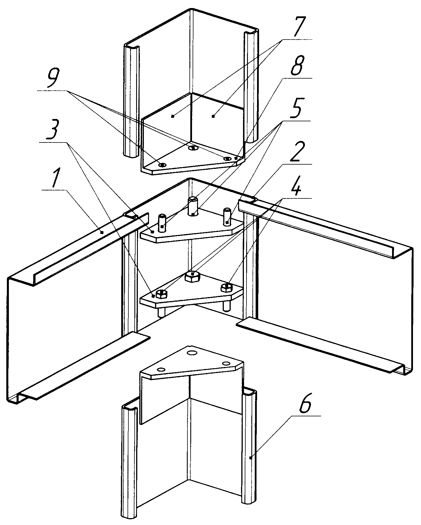
Каркас межэтажной панели состоит из гнутого профиля G-образной формы 1, соединенный сваркой по углам с фитингами уголковой формы с двухкратнозагнутыми вовнутрь полками 2. Внутри фитинга на равноудаленном от краев расстоянии приварены две косынки 3 треугольной формы. По углам косынок расположены отверстия 4, через которые установлены соединительные резьбовые элементы 5. Стойка изготовлена из профиля уголковой формы с двухкратнозагнутыми вовнутрь полками 6, на концах которого с внутренней стороны приварены планки 7, часть которых выступает за профиль 6 и снабжена треугольной формы косынкой 8 с отверстиями 9. При соединении каркаса панели со стойками выступающие части планок 7 входят во внутрь фитингов и крепятся болтовыми соединениями 5, проходящими через косынки фитингов и стоек. 2 н.п. ф-лы, 6 з.п. ф-лы, 3 илл.The frame of the interfloor panel consists of a bent profile of a G-shaped form 1, connected by welding at the corners with fittings of a corner shape with double-bent inward shelves 2. Inside the fitting, two triangles 3 are welded at an equal distance from the edges. Holes 4 are located at the corners of the headscarves, through which connecting threaded elements 5 are installed. The stand is made of a corner-shaped profile with shelves 6 double-bent inward, at the ends of which there are welded strips 7, some of which protrude beyond the profile 6 and are equipped with a triangular-shaped headscarf 8 sec holes 9. When connecting the frame of the panel to the racks, the protruding parts of the strips 7 enter the inside of the fittings and are fastened with bolt connections 5 passing through the scarves of the fittings and racks. 2 n.p. f-ly, 6 z.p. f-ly, 3 ill.
Description
Полезная модель относиться к строительству и может быть использована при возведении блок-контейнерных и сборно-разборных зданий различного назначения.The utility model relates to construction and can be used in the construction of block-container and collapsible buildings for various purposes.
Известна сборная секция модуля, включающая рамы верхнего и нижнего перекрытий, выполненные из полых гнутых профилей с опорными полками для вертикальных стоек, причем рамы верхнего и нижнего перекрытий соединены между собой с помощью отогнутых полок (Авторское свидетельство SU №916685, МПК Е04В 1/343, 1982 г.)Known prefabricated section of the module, including the upper and lower floors, made of hollow bent profiles with support shelves for vertical racks, and the frames of the upper and lower floors are interconnected using bent shelves (Copyright certificate SU No. 916685, IPC E04B 1/343, 1982)
Однако воздействие многоуровневых зданий с использованием указанных сборных секций приводит к дублированию межэтажного перекрытия верхним перекрытием сборной секции нижнего этажа и нижним перекрытием сборной секции верхнего этажа, что значительно увеличивает металлоемкость здания и затраты на его изготовление.However, the impact of multilevel buildings using the indicated prefabricated sections leads to duplication of the interfloor overlap with the upper overlap of the prefabricated section of the lower floor and the lower overlap of the prefabricated section of the upper floor, which significantly increases the metal consumption of the building and the cost of its manufacture.
Известна система соединения элементов пространственного каркаса здания, состоящего из соединяющего стойки с балками элемента, выполненного из двух уголков П-образного профиля и расположенными зеркально друг к другу в одной плоскости (Патент на полезную модель RU №67127, МПК Е04В 1/58, 2007).A known system of connecting the elements of the spatial frame of the building, consisting of connecting the pillars with the beams of the element, made of two corners of the U-shaped profile and located mirrored to each other in the same plane (Utility Model RU patent No. 67127, IPC Е04В 1/58, 2007) .
Такая система соединения элементов каркаса характеризуется множеством конструкций соединительных деталей, сложна в монтаже и предназначена в основном для узлов соединения деревянных элементов.Such a system of connecting frame elements is characterized by many designs of connecting parts, is difficult to install and is intended mainly for nodes connecting wooden elements.
Известен также узел этажного монтажа блок-контейнеров, включающий жесткие рамы верхнего и нижнего перекрытий и вертикальные стойки углового профиля, образующие четыре ловушки по углам каркаса за счет выведения вертикальной стойки выше перекрытия верхнего настила, а опорные элементы каркаса основания имеют скосы торцевых кромок и частично вырезанную Known also is the assembly unit for floor mounting of block containers, including rigid frames of the upper and lower floors and vertical racks of the angular profile, forming four traps at the corners of the frame due to the removal of the vertical rack above the ceiling of the upper flooring, and the supporting elements of the base frame have bevels of the end edges and partially cut
нижнюю полку для соединения с ловушкой верхнего настила (Патент на полезную модель RU №52031, МПК Е04В 1/343, 2006).the lower shelf for connection with the trap of the upper floor (Utility Model Patent RU No. 52031, IPC EV04 / 343, 2006).
К недостаткам указанного технического решения относиться дублирование межэтажного перекрытия верхним перекрытием нижней секции и нижним перекрытием верхней секции, а шплинтовое или болтовое соединение не обеспечивает достаточной герметичности и прочности соединения нижней и верхней секции.The disadvantages of this technical solution include duplication of floors between the upper overlap of the lower section and the lower overlap of the upper section, and the cotter pin or bolt connection does not provide sufficient tightness and strength of the connection of the lower and upper sections.
Наиболее близким к предлагаемому конструктивному решению является блок-контейнер, включающий жесткие рамы верхнего и нижнего перекрытий и вертикальные стойки трубчатого сечения с жестко закрепленными на концах вкладышами с отверстиями, соосными отверстиям на раме, и размещенный в них стяжной элемент. При этом рамы перекрытия снабжены вертикальными соединительными элементами в виде разрезного стакана, повторяющего сечение стойки, а выполненный в виде диафрагмы торцевой вкладыш снабжен вертикальным расклинивающим элементом (Патент на полезную модель RU №8713, МПК Е04В 1/348, 1998).Closest to the proposed constructive solution is a block container, comprising rigid frames of upper and lower floors and vertical struts of tubular section with liners rigidly fixed at the ends with holes, coaxial holes on the frame, and a coupling element located in them. At the same time, the overlapping frames are equipped with vertical connecting elements in the form of a split cup repeating the cross-section of the rack, and the end insert made in the form of a diaphragm is equipped with a vertical proppant (Utility Model Patent RU No. 8713, IPC Е04В 1/348, 1998).
К недостаткам данного прототипа является сложность конструкции, содержащей несколько специально изготовленных элементов, трудоемкость монтажа и низкая сопротивляемость динамическим нагрузкам.The disadvantages of this prototype are the complexity of the design, containing several specially made elements, the complexity of installation and low resistance to dynamic loads.
Целью предлагаемой полезной модели является снижение металлоемкости и затрат на изготовление, монтаж сборно-разборных зданий за счет упрощениям конструктивных элементов каркаса панели и стоек.The purpose of the proposed utility model is to reduce the metal consumption and manufacturing costs, installation of collapsible buildings due to simplifications of structural elements of the panel frame and racks.
Указанная цель достигается тем, что соединение каркаса межэтажной панели со стойками осуществляют за счет установки внутри фитингов каркаса панели косынок и приваренных внутри стоек планок, концы которых выступают за край гнутого профиля и вместе с косынкой входят вовнутрь фитинга и болтовым соединением закрепляются с косынками фитингов.This goal is achieved by the fact that the connection of the interfloor panel frame with the racks is carried out by installing inside the frame fittings a kerchief panel and strips welded inside the racks, the ends of which protrude beyond the edge of the bent profile and together with the scarf enter the inside of the fitting and are bolted to the kerchiefs of the fittings.
На фиг.1 приведены конструкции соединяемых элементов каркаса панели и стоек, на фиг.2 - вариант фитинга каркаса панели с одной косынкой, на фиг.3 - элемент каркаса панели в сборе со стойками.Figure 1 shows the construction of the connected elements of the frame of the panel and racks, figure 2 is a fitting version of the frame of the panel with one scarf, figure 3 is an element of the frame of the panel assembly with racks.
Каркас межэтажной панели (фиг.1) состоит из гнутого профиля G - образной формы 1, соединенного сваркой по углам с фитингами, изготовленными из профиля уголковой формы с двухкратнозагнутыми вовнутрь полками 2. Внутри фитингов установлены две косынки треугольной формы 3, по углам которых расположены отверстия 4. Для крепления стоек на косынках каркаса через отверстия 4 пропущены элементы резьбового соединения, например, в форме болтов 5, концы которых ориентированы в стороны присоединяемых стоек.The frame of the interfloor panel (Fig. 1) consists of a bent profile G - shaped form 1, connected by welding at the corners with fittings made of a corner shape profile with shelves double-bent inward 2. Inside the fittings are two triangular scarves 3, the corners of which have holes 4. For fastening the struts on the scarves of the frame through the holes 4, threaded elements, for example, in the form of bolts 5, the ends of which are oriented to the sides of the joined racks, are passed.
По другому варианту (фиг.2) внутри фитинга установлена одна косынка 3, с расположенными по обе стороны соединительными резьбовыми элементами 5.In another embodiment (Fig. 2), one kerchief 3 is installed inside the fitting, with threaded connecting elements 5 located on both sides.
Стойка для крепления межэтажной панели (фиг.1) состоит из профиля уголковой формы с двухкратнозагнутыми вовнутрь полками 6, на концах которых с внутренней стороны приварены две соединительные планки 7 так, что часть их выступает за пределы профиля 6. К выступам планок 7 приварена треугольной формы косынка 8 с отверстиями 9, совпадающими при соединении стойки с каркасом панели с соединительными элементами 5 фитинга. Высота выступа соединительных планок 7 с косынками 8 равна высоте между краем фитинга и установленной в нем косынкой 3.The rack for attaching the interfloor panel (Fig. 1) consists of a corner-shaped profile with shelves 6 double-bent inward, at the ends of which two connecting strips 7 are welded from the inside so that some of them protrude outside the profile 6. A triangular shape is welded to the protrusions of the strips 7 kerchief 8 with holes 9, matching when connecting the rack with the frame of the panel with the connecting elements 5 of the fitting. The height of the protrusion of the connecting strips 7 with the scarves 8 is equal to the height between the edge of the fitting and the scarf 3 installed therein.
Соединение каркаса межэтажной панели со стойками осуществляют следующим образом (фиг.1, 3). По углам панели основания устанавливают стойки, имеющие, по крайней мере, в верхней части соединительный элемент в форме приваренных изнутри к профилю стойки планок 7 с косынками 8. Каркас межэтажной панели устанавливают на стойки так, чтобы выступающие части планок 7 с косынками 8 стоек вошли вовнутрь фитингов каркасов панели. Затем на каркас панели устанавливают верхние стойки так, что элементы резьбового соединения 5, расположенные на косынке 3 каркаса, проходили через соответствующие отверстия 9 косынок 8 стоек, и осуществляют их крепление. При сборке следующего этажа операции сборки повторяют аналогично сборке второго этажа.The connection frame of the floor panel with racks is as follows (Fig.1, 3). At the corners of the base panel, racks are installed that have, at least in the upper part, a connecting element in the form of strips 7 with scarves welded internally to the rack profile 8. The interfloor panel frame is mounted on the racks so that the protruding parts of the strips 7 with the scarves 8 of the racks enter inside panel frame fittings. Then, the upper racks are installed on the panel frame so that the elements of the threaded connection 5 located on the scarf 3 of the frame pass through the corresponding holes 9 of the scarf 8 of the racks and fasten them. When assembling the next floor, the assembly operations are repeated similarly to the assembly of the second floor.
Таким образом, предлагаемое техническое решение имеет низкую металлоемкость, высокую прочность соединения стоек с межэтажными панелями и может быть использовано при строительстве сборно-разборных малоэтажных зданий.Thus, the proposed technical solution has a low metal consumption, high strength connection racks with floor panels and can be used in the construction of collapsible low-rise buildings.
Claims (8)
Priority Applications (1)
| Application Number | Priority Date | Filing Date | Title |
|---|---|---|---|
| RU2008130690/22U RU81507U1 (en) | 2008-07-24 | 2008-07-24 | CONNECTING THE INTERFACE PANEL FRAME WITH ANGULAR STANDS (OPTIONS) |
Applications Claiming Priority (1)
| Application Number | Priority Date | Filing Date | Title |
|---|---|---|---|
| RU2008130690/22U RU81507U1 (en) | 2008-07-24 | 2008-07-24 | CONNECTING THE INTERFACE PANEL FRAME WITH ANGULAR STANDS (OPTIONS) |
Publications (1)
| Publication Number | Publication Date |
|---|---|
| RU81507U1 true RU81507U1 (en) | 2009-03-20 |
Family
ID=40545626
Family Applications (1)
| Application Number | Title | Priority Date | Filing Date |
|---|---|---|---|
| RU2008130690/22U RU81507U1 (en) | 2008-07-24 | 2008-07-24 | CONNECTING THE INTERFACE PANEL FRAME WITH ANGULAR STANDS (OPTIONS) |
Country Status (1)
| Country | Link |
|---|---|
| RU (1) | RU81507U1 (en) |
Cited By (2)
| Publication number | Priority date | Publication date | Assignee | Title |
|---|---|---|---|---|
| RU2724575C1 (en) * | 2019-12-11 | 2020-06-23 | Акционерное общество "РМ РЕЙЛ АБАКАНВАГОНМАШ" (АО "РМ РЕЙЛ АБАКАНВАГОНМАШ") | Unit for connection of elements of metal frame of prefabricated buildings (versions) |
| RU2799216C1 (en) * | 2022-12-27 | 2023-07-04 | Ренат Тагирович Валиев | Connection for metal frame elements of prefabricated buildings |
-
2008
- 2008-07-24 RU RU2008130690/22U patent/RU81507U1/en not_active IP Right Cessation
Cited By (5)
| Publication number | Priority date | Publication date | Assignee | Title |
|---|---|---|---|---|
| RU2724575C1 (en) * | 2019-12-11 | 2020-06-23 | Акционерное общество "РМ РЕЙЛ АБАКАНВАГОНМАШ" (АО "РМ РЕЙЛ АБАКАНВАГОНМАШ") | Unit for connection of elements of metal frame of prefabricated buildings (versions) |
| RU2799216C1 (en) * | 2022-12-27 | 2023-07-04 | Ренат Тагирович Валиев | Connection for metal frame elements of prefabricated buildings |
| RU2804952C1 (en) * | 2023-02-21 | 2023-10-09 | Владислав Владимирович Трубчанинов | Metal frame building |
| RU2811578C1 (en) * | 2023-04-13 | 2024-01-15 | Ренат Тагирович Валиев | Prefabricated block-modular building (options) |
| RU219919U1 (en) * | 2023-05-04 | 2023-08-14 | Закрытое акционерное общество "АлтайСпецИзделия" (ЗАО "АлтайСпецИзделия") | Block container frame |
Similar Documents
| Publication | Publication Date | Title |
|---|---|---|
| CN109680993A (en) | A kind of removable box-type room | |
| RU2397295C2 (en) | Building frame | |
| KR101236592B1 (en) | Steel frame joint structure of unit modular house | |
| WO2013182997A1 (en) | Building unit and modular unit construction system comprising one or more such building units | |
| RU81507U1 (en) | CONNECTING THE INTERFACE PANEL FRAME WITH ANGULAR STANDS (OPTIONS) | |
| RU2375526C1 (en) | Set for assembling monohoneycomb structure frame unit and method of assembling with it | |
| RU94589U1 (en) | CONNECTING THE PANEL FRAME WITH THE STANDS | |
| RU98766U1 (en) | STAND PANEL CONNECTION ASSEMBLY | |
| KR101980663B1 (en) | Modular unit for container | |
| RU2401365C1 (en) | Portable structure (versions) | |
| CN207863171U (en) | A kind of pin-connected panel corridor case | |
| RU194610U1 (en) | ANGLE OF MODULAR DESIGN APPLICABLE IN CONSTRUCTION OF BUILDINGS AND CONSTRUCTIONS | |
| RU157581U1 (en) | Dismountable building construction | |
| JP6464459B2 (en) | Column base bracket, building unit including column base bracket, and installation method thereof | |
| RU201431U1 (en) | FAST ASSEMBLY-Dismountable STRUCTURE | |
| RU141235U1 (en) | DISASSEMBLY STAND AND ASSEMBLY CONNECTOR ASSEMBLY | |
| RU21406U1 (en) | BLOCK CONTAINER | |
| RU214833U1 (en) | Connecting node of mobile frame-modular buildings | |
| CN218205063U (en) | Supporting frame for building structure wall | |
| CN204001218U (en) | Assembly type beam column linkage | |
| JP3849847B2 (en) | Curtain wall system | |
| JP3159951U (en) | Panel parts set for assembly-type exhibition booth | |
| JP2665307B2 (en) | Wall panel mounting structure and beam material used for it | |
| JP6332979B2 (en) | Reinforcement structure of building unit | |
| RU52031U1 (en) | FLOOR INSTALLATION ASSEMBLY FOR METAL BLOCK CONTAINERS |
Legal Events
| Date | Code | Title | Description |
|---|---|---|---|
| MF1K | Cancelling a utility model patent |