RU2746576C2 - Immersion cooling - Google Patents
Immersion cooling Download PDFInfo
- Publication number
- RU2746576C2 RU2746576C2 RU2018142335A RU2018142335A RU2746576C2 RU 2746576 C2 RU2746576 C2 RU 2746576C2 RU 2018142335 A RU2018142335 A RU 2018142335A RU 2018142335 A RU2018142335 A RU 2018142335A RU 2746576 C2 RU2746576 C2 RU 2746576C2
- Authority
- RU
- Russia
- Prior art keywords
- heat transfer
- transfer fluid
- reservoir
- electronic equipment
- condenser
- Prior art date
Links
Images

Classifications
-
- H—ELECTRICITY
- H05—ELECTRIC TECHNIQUES NOT OTHERWISE PROVIDED FOR
- H05K—PRINTED CIRCUITS; CASINGS OR CONSTRUCTIONAL DETAILS OF ELECTRIC APPARATUS; MANUFACTURE OF ASSEMBLAGES OF ELECTRICAL COMPONENTS
- H05K7/00—Constructional details common to different types of electric apparatus
- H05K7/20—Modifications to facilitate cooling, ventilating, or heating
- H05K7/2029—Modifications to facilitate cooling, ventilating, or heating using a liquid coolant with phase change in electronic enclosures
- H05K7/203—Modifications to facilitate cooling, ventilating, or heating using a liquid coolant with phase change in electronic enclosures by immersion
-
- G—PHYSICS
- G06—COMPUTING; CALCULATING OR COUNTING
- G06F—ELECTRIC DIGITAL DATA PROCESSING
- G06F1/00—Details not covered by groups G06F3/00 - G06F13/00 and G06F21/00
- G06F1/16—Constructional details or arrangements
- G06F1/20—Cooling means
-
- H—ELECTRICITY
- H05—ELECTRIC TECHNIQUES NOT OTHERWISE PROVIDED FOR
- H05K—PRINTED CIRCUITS; CASINGS OR CONSTRUCTIONAL DETAILS OF ELECTRIC APPARATUS; MANUFACTURE OF ASSEMBLAGES OF ELECTRICAL COMPONENTS
- H05K7/00—Constructional details common to different types of electric apparatus
- H05K7/20—Modifications to facilitate cooling, ventilating, or heating
- H05K7/2029—Modifications to facilitate cooling, ventilating, or heating using a liquid coolant with phase change in electronic enclosures
- H05K7/20318—Condensers
-
- H—ELECTRICITY
- H05—ELECTRIC TECHNIQUES NOT OTHERWISE PROVIDED FOR
- H05K—PRINTED CIRCUITS; CASINGS OR CONSTRUCTIONAL DETAILS OF ELECTRIC APPARATUS; MANUFACTURE OF ASSEMBLAGES OF ELECTRICAL COMPONENTS
- H05K7/00—Constructional details common to different types of electric apparatus
- H05K7/20—Modifications to facilitate cooling, ventilating, or heating
- H05K7/2029—Modifications to facilitate cooling, ventilating, or heating using a liquid coolant with phase change in electronic enclosures
- H05K7/20381—Thermal management, e.g. evaporation control
-
- H—ELECTRICITY
- H05—ELECTRIC TECHNIQUES NOT OTHERWISE PROVIDED FOR
- H05K—PRINTED CIRCUITS; CASINGS OR CONSTRUCTIONAL DETAILS OF ELECTRIC APPARATUS; MANUFACTURE OF ASSEMBLAGES OF ELECTRICAL COMPONENTS
- H05K7/00—Constructional details common to different types of electric apparatus
- H05K7/20—Modifications to facilitate cooling, ventilating, or heating
- H05K7/20709—Modifications to facilitate cooling, ventilating, or heating for server racks or cabinets; for data centers, e.g. 19-inch computer racks
- H05K7/208—Liquid cooling with phase change
- H05K7/20818—Liquid cooling with phase change within cabinets for removing heat from server blades
Abstract
Description
Перекрёстная ссылка на родственные заявкиCross-referencing related claims
Настоящая заявка испрашивает преимущества заявки на изобретение U.K. No. GB1607662.2, поданной 3 мая 2016г., которая включена в настоящее описание во всей своей полноте путём ссылки.This application claims the benefits of U.K. No. GB1607662.2, filed May 3, 2016, which is incorporated herein in its entirety by reference.
Область техники, к которой относится изобретениеThe technical field to which the invention relates
Настоящее изобретение относится к охлаждению погружением, и более конкретно - к охлаждению электронного оборудования с помощью погружения.The present invention relates to immersion cooling, and more particularly to immersion cooling of electronic equipment.
Уровень техникиState of the art
Охлаждение погружением является технологией, используемой для охлаждения электронного оборудования для обработки данных, в частности оборудования для высокоскоростной обработки данных и для обработки большого объема данных, где традиционное воздушное охлаждение считается неудовлетворительным. Охлаждение погружением включает в себя погружение оборудования (например, электронных модулей для обработки данных) в резервуар, содержащий жидкость. Конвекция и испарение жидкости могут обеспечивать очень высокие скорости охлаждения, чтобы сохранять модули в пределах нормального диапазона рабочих температур. Вода не является идеальной жидкостью для использования в этих вариантах применения, потому что (а) она является электропроводящей, что означает необходимость использования какой-либо изоляции между водой и электроникой, тем самым снижая эффективность охлаждения и (b), поскольку вода испаряется при слишком высокой температуре. Вместо этого были разработаны более эффективные, непроводящие ток охлаждающие жидкости, которые испаряются при более низких температурах. Примером этого может служить жидкость NOVECTM 649, изготавливаемая фирмой 3MTM из Сент-Пол, штат Миннесота (США). Однако даже при использовании этих жидкостей могут возникнуть проблемы, если в жидкость попадает влага. Даже небольшое количество воды может вызвать замыкание электрических соединений в электронном оборудовании. Другая проблема заключается в том, что, поскольку специальные охлаждающие жидкости являются дорогостоящими, важно сохранить весь материал или как можно больше материала в сосуде, и свести к минимуму потери в результате испарения.Immersion cooling is a technology used to cool electronic data processing equipment, in particular high speed data processing equipment and large data processing equipment, where traditional air cooling is considered unsatisfactory. Immersion cooling involves immersing equipment (such as electronic data processing modules) in a reservoir containing liquid. Convection and liquid evaporation can provide very high cooling rates to keep modules within their normal operating temperature range. Water is not an ideal liquid to use in these applications because (a) it is electrically conductive, which means that some kind of insulation must be used between the water and the electronics, thereby reducing cooling efficiency, and (b) because water evaporates when too high temperature. Instead, more efficient, non-conductive coolants have been developed that evaporate at lower temperatures. An example of this is NOVECTM 649 fluid manufactured by 3M TM in St. Paul, Minnesota (USA). However, even with these fluids, problems can arise if moisture gets into the fluid. Even a small amount of water can short circuit electrical connections in electronic equipment. Another problem is that since specialty coolants are expensive, it is important to keep all or as much of the material in the vessel and minimize evaporation losses.
Ниже приводятся различные модификации и улучшения погружного охлаждения.Various modifications and improvements to immersion cooling are described below.
Сущность изобретенияThe essence of the invention
В одном аспекте настоящее изобретение обеспечивает способ погружного охлаждения электронного оборудования. Электронное оборудование погружается в герметизированный резервуар, находящийся под давлением, содержащий текучую среду для переноса тепла в жидкой форме. Резервуар содержит паросодержащее пространство над поверхностью жидкости, а паросодержащее пространство соединено с конденсатором. Электронное оборудование приводится в действие для генерирования тепла, чтобы испарить часть текучей среды для переноса тепла в жидкой форме и вызвать попадание паров текучей среды в конденсатор. Пары текучей среды для переноса тепла конденсируются в конденсаторе, в результате чего газообразная текучая среда для переноса тепла возвращается в жидкое состояние. Конденсат текучей среды для переноса тепла возвращается в резервуар. Потребление энергии электронным оборудованием увеличивается для увеличения генерируемого тепла и повышения избыточного давления паров жидкой текучей среды для переноса тепла, поскольку газообразная форма текучей среды для переноса тепла использует больше объема, чем его жидкая форма. Повышенное давление увеличивает эффективность конденсатора и изменение объёмной газообразной текучей среды для переноса тепла на более компактную жидкую фазу, что приводит систему в состояние равновесия.In one aspect, the present invention provides a method for immersion cooling of electronic equipment. Electronic equipment is immersed in a pressurized sealed reservoir containing a fluid for transferring heat in liquid form. The reservoir contains a steam-containing space above the surface of the liquid, and the steam-containing space is connected to the condenser. The electronic equipment is operated to generate heat to vaporize a portion of the heat transfer fluid in liquid form and cause fluid vapors to enter the condenser. The vapors of the heat transfer fluid are condensed in the condenser, with the result that the gaseous heat transfer fluid returns to a liquid state. Condensate from the heat transfer fluid is returned to the reservoir. The energy consumption of electronic equipment increases to increase the generated heat and increase the vapor pressure of the liquid fluid for heat transfer, since the gaseous form of the fluid uses more volume to transfer heat than its liquid form. The increased pressure increases the efficiency of the condenser and changes the bulk gaseous fluid to transfer heat to the more compact liquid phase, bringing the system into equilibrium.
Способ может дополнительно содержать снижение потребления энергии электронным оборудованием для уменьшения генерируемого тепла и вызывать снижение давления паров текучей среды для переноса тепла, при этом более низкое давление снижает температуру кипения жидкой фазы текучей среды для переноса тепла, чтобы снова привести систему в равновесие. Сниженная потребляемая мощность может вызвать развитие определённой степени вакуума внутри резервуара. Потребление энергии электронным оборудованием может быть уменьшено по существу до нуля, в результате чего давление паров текучей среды для переноса тепла в резервуаре снижается до значения около 0,4 бар (абсолютное).The method may further comprise reducing the energy consumption of the electronic equipment to reduce heat generated and cause the vapor pressure of the heat transfer fluid to decrease, the lower pressure lowering the boiling point of the liquid phase of the heat transfer fluid to bring the system back into equilibrium. Reduced power consumption can cause a certain degree of vacuum to develop inside the tank. The energy consumption of the electronic equipment can be reduced to substantially zero, with the result that the vapor pressure of the heat transfer fluid in the reservoir is reduced to about 0.4 bar (absolute).
Способ может дополнительно включать в себя фильтрацию конденсата для удаления влаги и/или металлических частиц перед возвратом конденсата в резервуар.The method may further include filtering the condensate to remove moisture and / or metal particles before returning the condensate to the reservoir.
Текучая среда для переноса тепла предпочтительно является диэлектрической жидкостью.The heat transfer fluid is preferably a dielectric fluid.
В некоторых вариантах осуществления изобретения этот способ может включать в себя признаки, которые чаще всего ассоциируются с другими способами, использующими резервуар без давления. Например, способ может дополнительно включать в себя конденсацию некоторого количества паров текучей среды для переноса тепла с помощью конденсаторных трубок в резервуаре.In some embodiments, the method may include features that are most commonly associated with other methods using a non-pressurized reservoir. For example, the method may further include condensing a quantity of the fluid vapor to transfer heat using condenser tubes in a reservoir.
В качестве другого примера этот способ может дополнительно включать в себя удаление влаги из воздуха в паросодержащем пространстве резервуара с помощью осушителя.As another example, this method may further include removing moisture from the air in the vapor-containing space of the vessel using a desiccant.
В другом аспекте настоящее изобретение обеспечивает устройство для охлаждения посредством погружения электронного оборудования. Герметизированный резервуар под давлением удерживает текучую среду для переноса тепла в жидкостной форме, в которую можно погружать электронное оборудование. Герметизированный резервуар под давлением включает в себя паросодержащее пространство над поверхностью жидкости. Конденсатор, имеющий впускное отверстие, соединенное с паросодержащим пространством, получает пары текучей среды для переноса тепла, и имеет уплотняемое выпускное отверстие для пара и выпускное отверстие для конденсата. Сконденсированная текучая среда для переноса тепла может возвращаться из выпускного отверстия для конденсата в резервуар через возвратную линию для конденсата.In another aspect, the present invention provides an apparatus for immersion cooling of electronic equipment. The pressurized container holds the heat transfer fluid in a liquid form in which electronic equipment can be immersed. The sealed pressure vessel includes a vapor-containing space above the surface of the liquid. The condenser having an inlet connected to the steam-containing space receives fluid vapors for heat transfer, and has a sealable steam outlet and a condensate outlet. The condensed heat transfer fluid can be returned from the condensate outlet to the reservoir via the condensate return line.
Устройство может дополнительно содержать фильтр в линии возврата конденсата для удаления влаги и/или металлических частиц.The device may further comprise a filter in the condensate return line to remove moisture and / or metal particles.
В некоторых вариантах осуществления изобретения устройство может включать в себя признаки, которые чаще всего ассоциируются с системой резервуаров без давления. Например, устройство может дополнительно содержать средства внутри резервуара для конденсации паров жидкого текучей среды для переноса тепла. Средства для конденсации могут содержать блок конденсаторных трубок.In some embodiments, the device may include features that are most commonly associated with a non-pressurized reservoir system. For example, the device may further comprise means within the vessel for condensing the vapor of the liquid fluid to transfer heat. Condensation means may contain a block of condenser tubes.
В качестве другого примера, устройство может дополнительно содержать осушитель для помощи в удалении влаги из воздуха в паросодержащем пространстве резервуара.As another example, the device may further comprise a desiccant to assist in removing moisture from the air in the vapor containing space of the vessel.
В другом аспекте изобретение обеспечивает способ инициирования охлаждения электронного оборудования посредством погружения. Электронное оборудование погружается в герметизированный резервуар, находящийся под давлением, удерживающий текучую среду для переноса тепла в жидком виде. Резервуар включает в себя паросодержащее пространство над поверхностью жидкости. Паросодержащее пространство соединяется с конденсатором, который расположен над резервуаром и включает в себя выпускное отверстие для пара с клапаном, действующим для герметизации выпускного отверстия для пара. Инициирование работы электронного оборудования, чтобы генерировать тепло для испарения некоторого количества текучей среды для переноса тепла и генерировать пар текучей среды для переноса тепла в паросодержащем пространстве. Клапан открывается, чтобы позволить созданным парам текучей среды для переноса тепла вытеснять воздух из паросодержащего пространства через конденсатор и наружу через выпускное отверстие для пара до тех пор, пока по существу весь воздух не будет вытеснен из паросодержащего пространства. Затем клапан закрывается, и в процессе своей работы электронное оборудование продолжает вырабатывать тепло, чтобы создавать пары текучей среды для переноса тепла. Пары текучей среды для переноса тепла конденсируются в конденсаторе, чтобы создавать конденсат текучей среды для переноса тепла, который возвращается в резервуар.In another aspect, the invention provides a method for initiating cooling of electronic equipment by immersion. The electronic equipment is immersed in a pressurized sealed reservoir that holds the fluid for transferring heat in liquid form. The reservoir includes a vapor-containing space above the surface of the liquid. The steam-containing space is connected to a condenser that is located above the reservoir and includes a steam outlet with a valve acting to seal the steam outlet. Initiating electronic equipment to generate heat to vaporize some of the heat transfer fluid and generate fluid vapor to transfer heat in the vapor containing space. The valve opens to allow the generated heat transfer fluid vapors to expel air from the vapor containing space through the condenser and out through the steam outlet until substantially all of the air has been expelled from the vapor containing space. The valve then closes and, as it operates, the electronic equipment continues to generate heat to create fluid vapors to transfer heat. The vapors of the heat transfer fluid are condensed in the condenser to create a condensate of the heat transfer fluid that is returned to the reservoir.
Краткое описание чертежейBrief Description of Drawings
Фиг. 1 - схематическая иллюстрация системы охлаждения погружением в соответствии с вариантами осуществления изобретения.FIG. 1 is a schematic illustration of an immersion cooling system in accordance with embodiments of the invention.
Фиг. 2 - схематическая иллюстрация другой системы охлаждения погружением.FIG. 2 is a schematic illustration of another immersion cooling system.
Фиг. 3 - блок-схема основных этапов способа охлаждения погружением в соответствии с вариантами осуществления изобретения.FIG. 3 is a flow diagram of the main steps of an immersion cooling method in accordance with embodiments of the invention.
Фиг. 4 - блок-схема основных этапов способа инициирования охлаждения погружением в соответствии с вариантами осуществления изобретения.FIG. 4 is a flow diagram of the main steps of a method for initiating immersion cooling in accordance with embodiments of the invention.
Подробное описаниеDetailed description
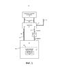
Фиг. 1 является схематической иллюстрацией системы охлаждения погружением. В этой системе конденсатор монтируется как отдельный компонент вне испарительного резервуара. Резервуар герметизируется от окружающей атмосферы и позволяет работать при переменном давлении. После того, как начальная процедура запуска завершена, в атмосфере резервуара нет воздуха, а только пар теплопередающей текучей среды.FIG. 1 is a schematic illustration of an immersion cooling system. In this system, the condenser is mounted as a separate component outside the flash tank. The reservoir is sealed from the surrounding atmosphere and allows operation at variable pressure. After the initial start-up procedure is complete, there is no air in the atmosphere of the reservoir, only steam from the heat transfer fluid.
Как показано на фиг. 1, электронные компоненты 10 погружаются в жидкую теплопередающую текучую среду 12, в герметичный резервуар 30. Жидкая теплопередающая текучая среда 12 имеет поверхность 13 в резервуаре 30, над которой находится пространство 15, заполненная паром. Жидкая теплопередающая текучая среда 12 отводит тепло от компонентов за счет конвекции и испарения внутри резервуара 30. Пар теплопередающей текучей среды 12 тяжелее воздуха.As shown in FIG. 1, electronic components 10 are immersed in a liquid
Вертикальный трубчатый стояк 32 проходит от отверстия 31 в крыше резервуара 30 к впускному отверстию 33 конденсатора 34. Конденсатор 34 включает в себя внутренние трубки (не показаны), через которые циркулирует охлаждающая жидкость (например, вода). Пар проходит через конденсатор в проходах между трубками к выпускному отверстию 35 для пара. Клапан 36 может быть открыт, чтобы воздух или пар проходил из выпускного отверстия 35 для пара в атмосферу, и может быть закрытым для герметизации выпускного отверстия 35 для пара. Конденсатор также имеет выпускное отверстие 37 для выхода конденсата в возвратную линию 39, через которую конденсат может протекать обратно в резервуар 30, и которая включает в себя проточный фильтр 38. Охлаждающая жидкость, которая циркулирует через конденсатор 34, возвращается в воздушный охладитель 40 для отвода тепла, которое отбирается из пара в конденсаторе.A vertical riser 32 extends from an opening 31 in the roof of
Для того чтобы теплопередающая жидкость и пар в резервуаре были полностью сухими, воздух в паровом пространстве 15 удаляется при запуске. Во время процедуры запуска, когда электропитание подается на электронное оборудование 10, и теплопередающая жидкость 12 начинает испаряться, давление в резервуаре 30 начинает повышаться. В этот момент клапан 36 открывается. Поскольку пар теплопередающей текучей среды более тяжелый, чем воздух, большая часть воздуха находится в конденсаторе 34 или в верхней части парового пространства 15. Когда клапан 36 открыт и на некоторую величину увеличивается давление внутри резервуара 30, воздух быстро выходит из системы через клапан 36. Воздух и пар, выходящие через клапан 36, могут быть направлены в систему очистки (не показана), которая конденсирует пар теплопередающей текучей среды в жидкую форму и высвобождает только воздух. Таким образом, во время пусковой последовательности можно сохранить некоторое дополнительное количество теплопередающей текучей среды. После этого клапан 36 закрывается, и резервуар 30 готов для длительного охлаждения.In order to keep the heat transfer liquid and vapor in the tank completely dry, the air in the
Пар теплопередающей текучей среды поднимается через трубчатый стояк 32 в конденсатор 34, где он конденсируется с образованием жидкого конденсата. Конденсат возвращается в резервуар 30 через возвратную линию 39 и фильтр 38. Фильтр 38 предусматривается для удаления остаточной влаги в конденсате и может также удалять металлические (например, медные) частицы, которые могли быть подхвачены жидкостью из конденсаторных трубок.The heat transfer fluid vapor rises through the riser 32 into the
В резервуаре есть точка равновесного состояния. При потреблении электронным оборудованием 10 определенной мощности (например, 250 кВт), определенном потоке воды через конденсатор 34 (например, 500 литров в минуту) и определенной температуре входной воды (например, 48°C), давление в резервуаре 30 является примерно нормальным (например, атмосферным). Давление в резервуаре 30 будет меняться с изменением потребляемой мощности электронным оборудованием 10. Если потребление мощности прекращается, то давление в резервуаре, как правило, падает до значения около 0,4 бар (абсолютное). Если мощность потребляется, но при более низком уровне, чем нормальный, внутри резервуара 30 возникает некоторая степень вакуума. Более низкое давление уменьшает температуру кипения теплопередающей текучей среды, приводя систему обратно в устойчивое равновесное состояние. Если потребление мощности более высокое, чем нормальное, тогда в резервуаре 30 возникает повышенное в некоторой степени давление. Из-за этого повышенного давления конденсатор 34 становится более эффективным, снова возвращая систему к устойчивому равновесию.There is an equilibrium point in the tank. When the electronic equipment 10 consumes a certain power (for example, 250 kW), a certain water flow through the condenser 34 (for example, 500 liters per minute) and a certain input water temperature (for example, 48 ° C), the pressure in the
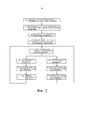
На фиг. 2 схематично иллюстрируется другая система погружного охлаждения. Эквивалентные компоненты обозначены теми же ссылочными позициями, что и на фиг. 1. В системе по фиг. 2 резервуар 14, который содержит теплопередающую текучую среду 12, предназначен для работы при практически постоянном давлении (например, атмосферном давлении). Как и в случае с системой на фиг. 1, электронное оборудование 10 погружается в жидкость 12 теплопередающей текучей среды, которая отводит тепло от электронного оборудования 10 посредством конвекции и испарения в резервуаре 14.FIG. 2 schematically illustrates another immersion cooling system. Equivalent components are designated by the same reference numerals as in FIG. 1. In the system of FIG. 2, the
Блоки труб 16 с водяным охлаждением действуют как конденсаторы для конденсации испарённой жидкости внутри резервуара 14. Чтобы гарантировать, что жидкость 12 теплопередающей текучей среды и атмосфера внутри резервуара 14 являются полностью сухими, атмосфера (испарённая текучая среда в воздухе) внутри резервуара 14 циркулирует через осушитель 18 (например, силикагель). Небольшой вентилятор (не показан) может использоваться для того, чтобы способствовать циркуляции через осушитель 18.The water-cooled
Вспомогательный конденсатор 22 располагается над резервуаром 14 и соединён с отверстием в крыше резервуара 14 с помощью трубчатого стояка 20. Вспомогательный конденсатор 22 также имеет выпускную трубку 24, которая соединена с камерой или объемом для расширения, эта камера в системе, изображённой на фиг. 1, представляет собой баллон 26. Также могут быть использованы другие виды расширительной камеры, такие как сильфон. Как основные конденсаторные трубки 16 в резервуаре 14, так и вспомогательный конденсатор 22 снабжаются охлаждающей водой, которая циркулирует через воздушные охладители 28 для удаления тепла, отобранного от конденсирующейся теплопередающей текучей среды.The
Атмосфера внутри резервуара 14 поддерживается по существу при постоянном давлении, которое обычно может быть атмосферным. Это помогает гарантировать, что жидкость 12 теплопередающей текучей среды продолжает испаряться для отвода тепла от электронных компонентов 10 с постоянной оптимальной скоростью. Для поддержания давления на практически постоянном уровне любое небольшое увеличение объема атмосферы в резервуаре 14 (например, из-за повышения температуры) приводит к восходящему потоку воздуха/пара в трубчатом стояке 20 и переносу этого потока во вспомогательный конденсатор 22. Пар из теплопередающей текучей среды конденсируется во вспомогательном конденсаторе 22 и возвращается под действием силы тяжести вниз по трубчатому стояку 20 и в резервуар 14. Баллон 26 поддерживает герметичность по отношению к внешней атмосфере (чтобы не допустить проникновения влаги в систему). Воздух/пар в трубчатом стояке 20 после прохождения через конденсатор 22 проходит в выпускную трубку 24, заставляя баллон 26 расширяться. Уменьшение объёма атмосферы резервуара 14 будет вызывать противоположный эффект, в результате чего баллон 26 сжимается.The atmosphere within the
Хотя две системы на фиг. 1 и 2 работают в разных режимах регулирования давления, следует принимать во внимание, что существует множество особенностей системы на фиг. 2, которые могут быть реализованы в системе по фиг. 1. Например, резервуар 30 в системе на фиг. 1 может включать в себя дополнительные блоки конденсаторных трубок, аналогичных основным конденсаторным трубам 16 на фиг. 2. Также может использоваться осушитель для облегчения удаления влаги из воздуха в паровом пространстве 15 резервуара на фиг. 1.Although the two systems in FIG. 1 and 2 operate in different pressure control modes, it should be appreciated that there are many features of the system in FIG. 2, which may be implemented in the system of FIG. 1. For example, the
Аналогичным образом могут существовать особенности системы, показанной на фиг. 1, которые могут быть реализованы в системе по фиг. 2. Например, отдельная труба возврата конденсата может быть установлена из вспомогательного конденсатора 22, чтобы установить фильтр для фильтрации конденсата. Кроме того, система на фиг. 2 может использовать способ удаления воздуха из резервуара 14 при запуске, аналогичный способу, описанному для системы по фиг. 1. В этом случае может быть предусмотрен клапан, который может открываться, чтобы позволять выпускной трубке 24 вентилировать атмосферу во время процедуры запуска.Likewise, features of the system shown in FIG. 1, which may be implemented in the system of FIG. 2. For example, a separate condensate return pipe can be installed from the
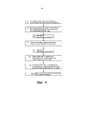
Как показано на фиг. 3, способ погружного охлаждения электронного оборудования начинается на этапе 101 путем погружения электронного оборудования в резервуар, такой как герметичный резервуар 30 под давлением, показанный на фиг. 1, содержащий текучую среду для переноса тепла (текучую среду h.t.)* в жидкой форме. На этапе 102 электронное оборудование приводится в действие и начинается генерирование тепла, а также испарение некоторой части текучей среды для переноса тепла, чтобы заставить пары текучей среды для переноса тепла входить в конденсатор. На этапе 103 пары текучей среды для переноса тепла конденсируются в конденсаторе, таком как конденсатор 34 на фиг.1, для получения конденсата текучей среды для переноса тепла. На этапе 104 конденсат текучей среды для переноса тепла возвращается в резервуар. Система принимает условие равновесия, в котором резервуар работает при стабилизированном давлении (например, атмосферном давлении).As shown in FIG. 3, the method for immersion cooling of electronic equipment begins at
После этапа 104 дальнейшая работа электронного оборудования может повлечь за собой увеличение или уменьшение мощности электронного оборудования. Увеличение потребления энергии электронным оборудованием, как показано на этапе 106а, приводит к увеличению генерируемого тепла, и на этапе 107а развивается повышенное давление паров текучей среды для переноса тепла. Повышенное давление приводит на этапе 108а к повышению эффективности конденсатора, чтобы вернуть систему в состояние равновесия (этап 105).After step 104, further operation of the electronic equipment may result in an increase or decrease in the power of the electronic equipment. The increase in energy consumption by the electronic equipment, as shown in step 106a, results in an increase in heat generated, and in step 107a, an increased vapor pressure of the heat transfer fluid develops. The increased pressure leads, in
Снижение потребления энергии электронным оборудованием, как показывается на этапе 106b, приводит к уменьшению генерируемого тепла, и на этапе 107b оказывает противоположный эффект, вызывая уменьшение давления паров текучей среды для переноса тепла.Reducing energy consumption by electronic equipment, as indicated in step 106b, results in a decrease in heat generated, and in step 107b has the opposite effect, causing the vapor pressure of the heat transfer fluid to decrease.
Как показано на фиг. 4, способ инициирования погружного охлаждения электронного оборудования начинается на этапе 201 посредством погружения электронного оборудования в резервуар, такой как герметичный резервуар 30 под давлением, показанный на фиг. 1, содержащий текучую среду для переноса тепла (текучую среду h.t.) в жидкой форме. На этапе 202 начинается работа электронного оборудования с одновременным началом генерирования тепла, чтобы испарить некоторую часть текучей среды для переноса тепла и создать пары текучей среды для переноса тепла. На этапе 203 открывается вентиляционный клапан (например, вентиляционный клапан 36 на фиг.1), таким образом на этапе 204 образующийся пар теплопередающей текучей среды вытесняет воздух, который проходит через конденсатор и выходит через вентиляционный клапан до тех пор, пока, по существу, весь воздух не будет вытеснен наружу. На этапе 205 вентиляционный клапан закрывается. На этапе 206 продолжается работа электронного оборудования, генерирование тепла и получение паров текучей среды для переноса тепла. На этапе 207 пары текучей среды для переноса тепла конденсируются в конденсаторе для получения конденсата теплопередающей текучей среды, который возвращается в резервуар на этапе 208.As shown in FIG. 4, the method for initiating immersion cooling of electronic equipment begins at
После описания некоторых вариантов осуществления изобретения, специалистам в данной области техники будет очевидно, что другие варианты осуществления, включающие раскрытые здесь понятия, могут использоваться без отклонения от сущности и объёма изобретения. Признаки и функции различных вариантов осуществления изобретения могут быть расположены в различных комбинациях и сочетаниях, и все они считаются входящими в объём раскрытого изобретения. Соответственно, описанные варианты осуществления изобретения должны рассматриваться во всех отношениях как иллюстративные, а не ограничительные. Конфигурации, материалы и размеры, описанные здесь, также предназначены в качестве иллюстративных и никоим образом не являются ограничивающими. Аналогичным образом, хотя физические пояснения были предоставлены для пояснительных целей, нет никакого намерения быть связанными какой-либо конкретной теорией или механизмом, или ограничить в соответствии с этим патентные притязания.After describing some embodiments of the invention, it will be apparent to those skilled in the art that other embodiments incorporating the concepts disclosed herein may be used without departing from the spirit and scope of the invention. The features and functions of the various embodiments of the invention may be arranged in various combinations and combinations, all of which are considered to be within the scope of the disclosed invention. Accordingly, the described embodiments of the invention are to be considered in all respects as illustrative and not restrictive. The configurations, materials, and dimensions described herein are also intended to be illustrative and are not limiting in any way. Likewise, although the physical explanations have been provided for illustrative purposes, there is no intent to be bound by any particular theory or mechanism, or to limit the patent claims accordingly.
Claims (29)
Applications Claiming Priority (3)
| Application Number | Priority Date | Filing Date | Title |
|---|---|---|---|
| GB1607662.2 | 2016-05-03 | ||
| GB1607662.2A GB2549946A (en) | 2016-05-03 | 2016-05-03 | Immersion cooling |
| PCT/IB2017/000711 WO2017191508A1 (en) | 2016-05-03 | 2017-05-02 | Immersion cooling |
Publications (3)
| Publication Number | Publication Date |
|---|---|
| RU2018142335A RU2018142335A (en) | 2020-06-04 |
| RU2018142335A3 RU2018142335A3 (en) | 2020-10-02 |
| RU2746576C2 true RU2746576C2 (en) | 2021-04-15 |
Family
ID=56234264
Family Applications (1)
| Application Number | Title | Priority Date | Filing Date |
|---|---|---|---|
| RU2018142335A RU2746576C2 (en) | 2016-05-03 | 2017-05-02 | Immersion cooling |
Country Status (13)
| Country | Link |
|---|---|
| US (2) | US10206307B2 (en) |
| EP (1) | EP3453235B1 (en) |
| JP (1) | JP2019516195A (en) |
| KR (2) | KR102425144B1 (en) |
| CN (1) | CN108141991B (en) |
| CA (1) | CA3022767A1 (en) |
| DK (1) | DK3453235T3 (en) |
| ES (1) | ES2880481T3 (en) |
| GB (1) | GB2549946A (en) |
| IL (2) | IL262645B (en) |
| RU (1) | RU2746576C2 (en) |
| SG (2) | SG11201809682UA (en) |
| WO (1) | WO2017191508A1 (en) |
Families Citing this family (47)
| Publication number | Priority date | Publication date | Assignee | Title |
|---|---|---|---|---|
| JP6042590B1 (en) * | 2015-11-16 | 2016-12-14 | 株式会社ExaScaler | Immersion cooling electronic device and cooling system using the same |
| GB2549946A (en) * | 2016-05-03 | 2017-11-08 | Bitfury Group Ltd | Immersion cooling |
| GB2550356B (en) * | 2016-05-16 | 2021-11-17 | Bitfury Group Ltd | Filter for immersion cooling apparatus |
| CN109871096A (en) * | 2017-11-17 | 2019-06-11 | 英业达科技有限公司 | Cooling control method and its immersion cooling system |
| CN107979955B (en) * | 2017-11-24 | 2020-06-30 | 北京百度网讯科技有限公司 | Modularized liquid cooling server case |
| US20190357378A1 (en) * | 2018-05-18 | 2019-11-21 | Tas Energy Inc. | Two-phase immersion cooling system and method with enhanced circulation of vapor flow through a condenser |
| US10694643B2 (en) | 2018-09-19 | 2020-06-23 | TMGCore, LLC | Ballast blocks for a liquid immersion cooling system |
| US10624237B2 (en) | 2018-09-19 | 2020-04-14 | TMGCore, LLC | Liquid immersion cooling vessel and components thereof |
| US11102912B2 (en) | 2018-09-19 | 2021-08-24 | TMGCore, LLC | Liquid immersion cooling platform |
| US10617032B1 (en) | 2018-09-19 | 2020-04-07 | TMGCore, LLC | Robot for a liquid immersion cooling system |
| US10969842B2 (en) | 2018-09-19 | 2021-04-06 | TMGCore, LLC | Chassis for a liquid immersion cooling system |
| US10653043B2 (en) | 2018-09-19 | 2020-05-12 | TMGCore, LLC | Vapor management system for a liquid immersion cooling system |
| US11129298B2 (en) | 2018-09-19 | 2021-09-21 | Tmgcore, Inc. | Process for liquid immersion cooling |
| US11895804B2 (en) | 2018-09-19 | 2024-02-06 | Tmgcore, Inc. | Fluid breakdown detection systems and processes useful for liquid immersion cooling |
| CN109168306A (en) * | 2018-10-26 | 2019-01-08 | 英业达科技有限公司 | cooling device |
| US11785747B2 (en) | 2018-11-16 | 2023-10-10 | TMGCore. INC. | Methods and devices for testing immersion cooling controllers |
| US10939580B2 (en) * | 2019-03-25 | 2021-03-02 | Baidu Usa Llc | Control strategy for immersion cooling system |
| US10773192B1 (en) * | 2019-04-09 | 2020-09-15 | Bitfury Ip B.V. | Method and apparatus for recovering dielectric fluids used for immersion cooling |
| US10916818B2 (en) * | 2019-06-21 | 2021-02-09 | Baidu Usa Llc | Self-activating thermal management system for battery pack |
| CN110471518A (en) * | 2019-08-08 | 2019-11-19 | 昆山艾纳电子科技有限公司 | Immersion heat dissipation tank |
| US11076508B2 (en) * | 2019-11-14 | 2021-07-27 | Baidu Usa Llc | Cooling systems for immersion cooled IT equipment |
| US11160194B2 (en) * | 2019-11-14 | 2021-10-26 | Liquidstack Holding B.V. | Hot swap condensor for immersion cooling |
| US10966349B1 (en) * | 2020-07-27 | 2021-03-30 | Bitfury Ip B.V. | Two-phase immersion cooling apparatus with active vapor management |
| US11392184B2 (en) * | 2020-09-25 | 2022-07-19 | Microsoft Technology Licensing, Llc | Disaggregated computer systems |
| CN114518791A (en) * | 2020-11-19 | 2022-05-20 | 英业达科技有限公司 | Cooling system of server |
| US11721858B2 (en) | 2020-12-11 | 2023-08-08 | Kesavan Moses Srivilliputhur | SuCCoR: a super critical cooling regulator to mitigate heating of batteries and other devices |
| WO2022177715A1 (en) * | 2021-02-17 | 2022-08-25 | Microsoft Technology Licensing, Llc | Two phase coolant management |
| JP2022158103A (en) | 2021-04-01 | 2022-10-17 | 三菱重工業株式会社 | cooling system |
| US11792962B2 (en) * | 2021-05-05 | 2023-10-17 | Microsoft Technology Licensing, Llc | Systems and methods for immersion-cooled datacenters |
| TWI799854B (en) * | 2021-05-07 | 2023-04-21 | 緯穎科技服務股份有限公司 | Immersion cooling system, electronic apparatus having the same and pressure adjusting module |
| TWI807318B (en) * | 2021-05-07 | 2023-07-01 | 緯穎科技服務股份有限公司 | Electronic apparatus having immersion cooling system and operating method thereof |
| CN115388316B (en) * | 2021-05-25 | 2024-01-26 | 英业达科技有限公司 | Gas storage device and two-phase immersed cooling system |
| US11778791B2 (en) * | 2021-06-15 | 2023-10-03 | Baidu Usa Llc | Two phase containment system for servers |
| US11723176B2 (en) * | 2021-06-22 | 2023-08-08 | Baidu Usa Llc | Multi-tier cooling system without load perception |
| US11805622B2 (en) * | 2021-06-24 | 2023-10-31 | Baidu Usa Llc | Two phase immersion cooling system with dual condenser units |
| US20230026658A1 (en) * | 2021-07-21 | 2023-01-26 | Delta Electronics, Inc. | Immersion cooling system |
| TWI796929B (en) * | 2021-07-21 | 2023-03-21 | 台達電子工業股份有限公司 | Immersion cooling system |
| US20230027552A1 (en) * | 2021-07-23 | 2023-01-26 | Super Micro Computer, Inc. | Fluid immersion cooling system with multiple layers of coolant fluids |
| US11612081B2 (en) * | 2021-08-23 | 2023-03-21 | Baidu Usa Llc | Two phase containment system having controlled air flow |
| US20230067857A1 (en) * | 2021-09-02 | 2023-03-02 | Baidu Usa Llc | Enclosed condensing package for electronic racks |
| US20210410320A1 (en) * | 2021-09-13 | 2021-12-30 | Intel Corporation | Immersion cooling system with coolant boiling point reduction for increased cooling capacity |
| US11903163B2 (en) | 2021-10-11 | 2024-02-13 | Tmgcore, Inc. | Methods and devices to employ air cooled computers in liquid immersion cooling |
| WO2023121701A1 (en) * | 2021-12-24 | 2023-06-29 | Intel Corporation | Immersion cooling systems, apparatus, and related methods |
| WO2023139433A2 (en) * | 2022-01-18 | 2023-07-27 | Liquidstack Holding B.V. | Actively controlled immersion cooling system and method |
| TWI816465B (en) * | 2022-07-08 | 2023-09-21 | 緯穎科技服務股份有限公司 | Immersion cooling system |
| DE102022002696B3 (en) | 2022-07-25 | 2023-03-30 | Wieland-Werke Aktiengesellschaft | Cooling system for liquid immersion cooling of electronic components |
| US11825631B1 (en) * | 2023-05-16 | 2023-11-21 | MTS IP Holdings Ltd | Bellows for immersion cooling |
Citations (4)
| Publication number | Priority date | Publication date | Assignee | Title |
|---|---|---|---|---|
| US20080115528A1 (en) * | 2006-11-17 | 2008-05-22 | Denso Corporation | Cooling module |
| US20150062806A1 (en) * | 2013-02-01 | 2015-03-05 | Dell Products L.P. | Immersion Server, Immersion Server Drawer, and Rack-Mountable Immersion Server Drawer-Based Cabinet |
| US20150109730A1 (en) * | 2013-10-21 | 2015-04-23 | International Business Machines Corporation | Direct coolant contact vapor condensing |
| RU156137U1 (en) * | 2015-04-06 | 2015-10-27 | Андрей Витальевич Давыдов | DEVICE FOR PASSIVE TWO PHASE IMMERSION COOLING OF ELECTRONIC EQUIPMENT |
Family Cites Families (76)
| Publication number | Priority date | Publication date | Assignee | Title |
|---|---|---|---|---|
| FR1064730A (en) | 1951-07-02 | 1954-05-17 | Westinghouse Electric Corp | Oil conditioner |
| US3406244A (en) | 1966-06-07 | 1968-10-15 | Ibm | Multi-liquid heat transfer |
| US3774677A (en) | 1971-02-26 | 1973-11-27 | Ibm | Cooling system providing spray type condensation |
| JPS5062326A (en) * | 1973-10-01 | 1975-05-28 | ||
| JPS5824451Y2 (en) * | 1974-10-16 | 1983-05-25 | 工業技術院長 | Jiyo Hatsurei Yakusouchi |
| JPS583358Y2 (en) * | 1977-09-19 | 1983-01-20 | 株式会社東芝 | Boiling cooling device |
| GB1595094A (en) * | 1977-10-19 | 1981-08-05 | Gen Electric | Method and system for cooling electrical apparatus |
| FR2413624A1 (en) * | 1977-12-28 | 1979-07-27 | Matra Engins | Electronic circuit cooling device - has expansion chamber and non-return valve to prevent air from being drawn into refrigerant vessel |
| US4590538A (en) | 1982-11-18 | 1986-05-20 | Cray Research, Inc. | Immersion cooled high density electronic assembly |
| JPS59103318A (en) * | 1982-12-03 | 1984-06-14 | Mitsubishi Electric Corp | Apparatus for cooling machine or equipment |
| JPS5995641U (en) * | 1983-09-29 | 1984-06-28 | 三菱電機株式会社 | Boiling cooling type electrical equipment |
| JPH04256346A (en) | 1991-02-08 | 1992-09-11 | Fujitsu Ltd | Structure of electronic component for immersion cooling |
| US5131233A (en) * | 1991-03-08 | 1992-07-21 | Cray Computer Corporation | Gas-liquid forced turbulence cooling |
| US5305184A (en) | 1992-12-16 | 1994-04-19 | Ibm Corporation | Method and apparatus for immersion cooling or an electronic board |
| JPH06275749A (en) * | 1993-03-18 | 1994-09-30 | Hitachi Ltd | Boiling/cooling apparatus |
| US5463872A (en) | 1994-09-08 | 1995-11-07 | International Business Machines Corporation | High performance thermal interface for low temperature electronic modules |
| FR2738446B1 (en) | 1995-08-30 | 1997-09-26 | Gec Alsthom Transport Sa | METHOD AND DEVICE FOR FILTERING AN ELECTRIC INSULATING LIQUID MEDIUM AND CALORIPORATOR AND ELECTRONIC POWER UNIT INCLUDING SUCH A DEVICE |
| US6019167A (en) | 1997-12-19 | 2000-02-01 | Nortel Networks Corporation | Liquid immersion cooling apparatus for electronic systems operating in thermally uncontrolled environments |
| GB2389174B (en) * | 2002-05-01 | 2005-10-26 | Rolls Royce Plc | Cooling systems |
| US6687124B2 (en) | 2002-06-24 | 2004-02-03 | General Motors Corporation | Apparatus for cooling electronic components in a phase change electronic cooling system |
| US6879115B2 (en) | 2002-07-09 | 2005-04-12 | International Rectifier Corporation | Adaptive ballast control IC |
| US20070034360A1 (en) | 2005-06-08 | 2007-02-15 | Hall Jack P | High performance cooling assembly for electronics |
| GB2432460B8 (en) | 2005-11-17 | 2010-08-18 | Iceotope Ltd | Computer apparatus |
| CN101270940A (en) * | 2008-01-30 | 2008-09-24 | 刘克里 | Integral cooling and grading condensation heat pump type waste heat recovery shower-bath device |
| US7983040B2 (en) | 2008-10-23 | 2011-07-19 | International Business Machines Corporation | Apparatus and method for facilitating pumped immersion-cooling of an electronic subsystem |
| US7916483B2 (en) | 2008-10-23 | 2011-03-29 | International Business Machines Corporation | Open flow cold plate for liquid cooled electronic packages |
| US7885070B2 (en) | 2008-10-23 | 2011-02-08 | International Business Machines Corporation | Apparatus and method for immersion-cooling of an electronic system utilizing coolant jet impingement and coolant wash flow |
| US7944694B2 (en) | 2008-10-23 | 2011-05-17 | International Business Machines Corporation | Liquid cooling apparatus and method for cooling blades of an electronic system chassis |
| US7961475B2 (en) | 2008-10-23 | 2011-06-14 | International Business Machines Corporation | Apparatus and method for facilitating immersion-cooling of an electronic subsystem |
| US7724524B1 (en) | 2008-11-12 | 2010-05-25 | International Business Machines Corporation | Hybrid immersion cooled server with integral spot and bath cooling |
| WO2010058520A1 (en) * | 2008-11-18 | 2010-05-27 | 日本電気株式会社 | Boiling and cooling device |
| US8018720B2 (en) | 2009-06-25 | 2011-09-13 | International Business Machines Corporation | Condenser structures with fin cavities facilitating vapor condensation cooling of coolant |
| US8014150B2 (en) | 2009-06-25 | 2011-09-06 | International Business Machines Corporation | Cooled electronic module with pump-enhanced, dielectric fluid immersion-cooling |
| US8059405B2 (en) | 2009-06-25 | 2011-11-15 | International Business Machines Corporation | Condenser block structures with cavities facilitating vapor condensation cooling of coolant |
| US8351206B2 (en) | 2010-06-29 | 2013-01-08 | International Business Machines Corporation | Liquid-cooled electronics rack with immersion-cooled electronic subsystems and vertically-mounted, vapor-condensing unit |
| US8369091B2 (en) | 2010-06-29 | 2013-02-05 | International Business Machines Corporation | Interleaved, immersion-cooling apparatus and method for an electronic subsystem of an electronics rack |
| US8345423B2 (en) | 2010-06-29 | 2013-01-01 | International Business Machines Corporation | Interleaved, immersion-cooling apparatuses and methods for cooling electronic subsystems |
| US8179677B2 (en) | 2010-06-29 | 2012-05-15 | International Business Machines Corporation | Immersion-cooling apparatus and method for an electronic subsystem of an electronics rack |
| US8184436B2 (en) | 2010-06-29 | 2012-05-22 | International Business Machines Corporation | Liquid-cooled electronics rack with immersion-cooled electronic subsystems |
| TWI488562B (en) | 2010-08-30 | 2015-06-11 | Liquidcool Solutions Inc | Extruded server case |
| WO2012030473A2 (en) | 2010-08-30 | 2012-03-08 | Hardcore Computer, Inc. | Server case with optical input/output and/or wireless power supply |
| US8867209B2 (en) | 2011-07-21 | 2014-10-21 | International Business Machines Corporation | Two-phase, water-based immersion-cooling apparatus with passive deionization |
| US8959941B2 (en) | 2011-07-21 | 2015-02-24 | International Business Machines Corporation | Data center cooling with an air-side economizer and liquid-cooled electronics rack(s) |
| US8955347B2 (en) | 2011-07-21 | 2015-02-17 | International Business Machines Corporation | Air-side economizer facilitating liquid-based cooling of an electronics rack |
| WO2012149768A1 (en) | 2011-09-23 | 2012-11-08 | 华为技术有限公司 | Submerged cooling system and method |
| US20130091866A1 (en) | 2011-10-12 | 2013-04-18 | International Business Machines Corporation | Thermoelectric-enhanced, vapor-condenser facilitating immersion-cooling of electronic component(s) |
| US8619425B2 (en) | 2011-10-26 | 2013-12-31 | International Business Machines Corporation | Multi-fluid, two-phase immersion-cooling of electronic component(s) |
| US8953317B2 (en) | 2011-10-26 | 2015-02-10 | International Business Machines Corporation | Wicking vapor-condenser facilitating immersion-cooling of electronic component(s) |
| CN102510709B (en) | 2011-11-21 | 2015-03-11 | 华为机器有限公司 | Immersion cooling electronic equipment |
| CN102842406A (en) | 2012-08-31 | 2012-12-26 | 深圳供电局有限公司 | Constant voltage condenser of evaporative-cooling-liquid-immersed transformer |
| US8941994B2 (en) | 2012-09-13 | 2015-01-27 | International Business Machines Corporation | Vapor condenser with three-dimensional folded structure |
| US8953320B2 (en) | 2012-09-13 | 2015-02-10 | Levi A. Campbell | Coolant drip facilitating partial immersion-cooling of electronic components |
| US9095942B2 (en) | 2012-09-26 | 2015-08-04 | International Business Machines Corporation | Wicking and coupling element(s) facilitating evaporative cooling of component(s) |
| US8934250B2 (en) | 2012-09-26 | 2015-01-13 | International Business Machines Corporation | Immersion-cooling of selected electronic component(s) mounted to printed circuit board |
| US9261308B2 (en) | 2012-11-08 | 2016-02-16 | International Business Machines Corporation | Pump-enhanced, sub-cooling of immersion-cooling fluid |
| US8964390B2 (en) | 2012-11-08 | 2015-02-24 | International Business Machines Corporation | Sectioned manifolds facilitating pumped immersion-cooling of electronic components |
| US9042098B2 (en) | 2012-11-12 | 2015-05-26 | International Business Machines Corporation | Air-cooling and vapor-condensing door assembly |
| US8947873B2 (en) | 2012-11-26 | 2015-02-03 | International Business Machines Corporation | Immersion-cooled and conduction-cooled electronic system |
| CN104937067A (en) | 2013-01-24 | 2015-09-23 | 陶氏环球技术有限责任公司 | Liquid cooling medium for electronic device cooling |
| US20150319889A1 (en) | 2013-01-24 | 2015-11-05 | Dow Global Technologies Llc | Liquid cooling medium for electronic device cooling |
| US9351429B2 (en) | 2013-02-01 | 2016-05-24 | Dell Products, L.P. | Scalable, multi-vessel distribution system for liquid level control within immersion cooling tanks |
| US9464854B2 (en) | 2013-02-01 | 2016-10-11 | Dell Products, Lp | Techniques for controlling vapor pressure in an immersion cooling tank |
| US9335802B2 (en) * | 2013-02-01 | 2016-05-10 | Dell Products, L.P. | System for cooling hard disk drives using vapor momentum driven by boiling of dielectric liquid |
| US9144179B2 (en) * | 2013-02-01 | 2015-09-22 | Dell Products, L.P. | System and method for powering multiple electronic devices operating within an immersion cooling vessel |
| US9328964B2 (en) | 2013-02-01 | 2016-05-03 | Dell Products, L.P. | Partitioned, rotating condenser units to enable servicing of submerged it equipment positioned beneath a vapor condenser without interrupting a vaporization-condensation cycling of the remaining immersion cooling system |
| JP2014214985A (en) | 2013-04-26 | 2014-11-17 | 富士通株式会社 | Evaporator, cooler, and electronic apparatus |
| US9414520B2 (en) | 2013-05-28 | 2016-08-09 | Hamilton Sundstrand Corporation | Immersion cooled motor controller |
| US20150022975A1 (en) | 2013-07-19 | 2015-01-22 | General Electric Company | Method and system for an immersion boiling heat sink |
| US9332674B2 (en) | 2013-10-21 | 2016-05-03 | International Business Machines Corporation | Field-replaceable bank of immersion-cooled electronic components |
| US9357675B2 (en) | 2013-10-21 | 2016-05-31 | International Business Machines Corporation | Pump-enhanced, immersion-cooling of electronic component(s) |
| US9282678B2 (en) | 2013-10-21 | 2016-03-08 | International Business Machines Corporation | Field-replaceable bank of immersion-cooled electronic components and separable heat sinks |
| FR3015645B1 (en) | 2013-12-20 | 2018-04-13 | Stymergy | DEVICE FOR HEATING A LIQUID |
| CN104166448A (en) | 2014-08-20 | 2014-11-26 | 浪潮电子信息产业股份有限公司 | Immersion-type server cooling device |
| CN204968334U (en) * | 2015-10-12 | 2016-01-13 | 讯凯国际股份有限公司 | Heat dissipating system |
| GB2549946A (en) * | 2016-05-03 | 2017-11-08 | Bitfury Group Ltd | Immersion cooling |
| GB2550356B (en) * | 2016-05-16 | 2021-11-17 | Bitfury Group Ltd | Filter for immersion cooling apparatus |
-
2016
- 2016-05-03 GB GB1607662.2A patent/GB2549946A/en not_active Withdrawn
-
2017
- 2017-05-02 SG SG11201809682UA patent/SG11201809682UA/en unknown
- 2017-05-02 CA CA3022767A patent/CA3022767A1/en active Pending
- 2017-05-02 US US15/584,670 patent/US10206307B2/en active Active
- 2017-05-02 SG SG10202010879WA patent/SG10202010879WA/en unknown
- 2017-05-02 IL IL262645A patent/IL262645B/en unknown
- 2017-05-02 IL IL293689A patent/IL293689A/en unknown
- 2017-05-02 JP JP2018558298A patent/JP2019516195A/en active Pending
- 2017-05-02 KR KR1020187035010A patent/KR102425144B1/en active IP Right Grant
- 2017-05-02 EP EP17734451.2A patent/EP3453235B1/en active Active
- 2017-05-02 DK DK17734451.2T patent/DK3453235T3/en active
- 2017-05-02 WO PCT/IB2017/000711 patent/WO2017191508A1/en unknown
- 2017-05-02 RU RU2018142335A patent/RU2746576C2/en active
- 2017-05-02 CN CN201780002638.0A patent/CN108141991B/en active Active
- 2017-05-02 KR KR1020227025171A patent/KR20220108193A/en not_active Application Discontinuation
- 2017-05-02 ES ES17734451T patent/ES2880481T3/en active Active
-
2019
- 2019-01-08 US US16/242,332 patent/US20190223316A1/en not_active Abandoned
Patent Citations (4)
| Publication number | Priority date | Publication date | Assignee | Title |
|---|---|---|---|---|
| US20080115528A1 (en) * | 2006-11-17 | 2008-05-22 | Denso Corporation | Cooling module |
| US20150062806A1 (en) * | 2013-02-01 | 2015-03-05 | Dell Products L.P. | Immersion Server, Immersion Server Drawer, and Rack-Mountable Immersion Server Drawer-Based Cabinet |
| US20150109730A1 (en) * | 2013-10-21 | 2015-04-23 | International Business Machines Corporation | Direct coolant contact vapor condensing |
| RU156137U1 (en) * | 2015-04-06 | 2015-10-27 | Андрей Витальевич Давыдов | DEVICE FOR PASSIVE TWO PHASE IMMERSION COOLING OF ELECTRONIC EQUIPMENT |
Non-Patent Citations (5)
| Title |
|---|
| CINDY M BARNES et al Practical Considerations Relating to Immersion Cooling of Rower Electronics in Traction Systems, IEEE Trans. On Power ELECTRONICS, v.25,no.9, 01.09.2010, гл.III. Anon : "3M(TM) Two-Phase Immersion Cooling- High Level Best Practices for System Fabrication", 0106.2015, Части 4 и 5, Извлечено из Интернет URL: https://multimedia.3m.com/mws/media/10102660/3m-two-phase-immersion-cooling-best-practices- technical-paper.pdf. * |
| RAMASWAMY C ET AL, "COMBINED EFFECTS OF SUB-COOLING AND OPERATING PRESSURE ON THE PERFORMANCE OF A TWO-CHAMBER THERMOSYPHON", IEEE TRANSACTIONS ON COMPONENTS AND PACKAGING TECHNOLOGIES, 01.03.2000 vol. 23, no. 1. * |
| RAMASWAMY C ET AL, "COMBINED EFFECTS OF SUB-COOLING AND OPERATING PRESSURE ON THE PERFORMANCE OF A TWO-CHAMBER THERMOSYPHON", IEEE TRANSACTIONS ON COMPONENTS AND PACKAGING TECHNOLOGIES, 01.03.2000 vol. 23, no. 1. SIMONS R E ET AL, "A SURVEY OF VAPOR PHASE COOLING SYSTEMS", * |
| SIMONS R E ET AL, "A SURVEY OF VAPOR PHASE COOLING SYSTEMS", ELECTRICAL DESIGN NEWS 01.01.1969 vol. 14, no. 1, pages 53 - 56, 7,11,12,14, figures 3,6,7, Section Test Method.. * |
| vol. 14, no. 1, pages 53 - 56, 7,11,12,14, figures 3,6,7, Section Test Method.. * |
Also Published As
| Publication number | Publication date |
|---|---|
| CN108141991A (en) | 2018-06-08 |
| IL262645B (en) | 2022-07-01 |
| US20170325355A1 (en) | 2017-11-09 |
| CA3022767A1 (en) | 2017-11-09 |
| KR20220108193A (en) | 2022-08-02 |
| WO2017191508A1 (en) | 2017-11-09 |
| DK3453235T3 (en) | 2021-07-26 |
| ES2880481T3 (en) | 2021-11-24 |
| GB201607662D0 (en) | 2016-06-15 |
| SG10202010879WA (en) | 2020-12-30 |
| EP3453235B1 (en) | 2021-04-21 |
| EP3453235A1 (en) | 2019-03-13 |
| SG11201809682UA (en) | 2018-11-29 |
| CN108141991B (en) | 2020-11-06 |
| IL293689A (en) | 2022-08-01 |
| RU2018142335A (en) | 2020-06-04 |
| JP2019516195A (en) | 2019-06-13 |
| US10206307B2 (en) | 2019-02-12 |
| GB2549946A (en) | 2017-11-08 |
| US20190223316A1 (en) | 2019-07-18 |
| IL262645A (en) | 2018-12-31 |
| KR20190019928A (en) | 2019-02-27 |
| RU2018142335A3 (en) | 2020-10-02 |
| KR102425144B1 (en) | 2022-07-29 |
Similar Documents
| Publication | Publication Date | Title |
|---|---|---|
| RU2746576C2 (en) | Immersion cooling | |
| JP6658888B2 (en) | Cooling device and electronic device | |
| TW202219682A (en) | Two-phase immersion cooling apparatus with active vapor managemfent | |
| US4424633A (en) | Apparatus for heating and drying articles | |
| US6732448B2 (en) | Device for preparing transformers | |
| US20220232738A1 (en) | Refrigerant vapor adsorption from two phase immersion cooling system | |
| JP2007127334A (en) | Heating medium heating and cooling device | |
| US20230156961A1 (en) | Two-phase immersion cooling device with movable second condenser | |
| JP5782368B2 (en) | Vacuum drying equipment | |
| NO146560B (en) | EVAPORATING COOLING EVAPORATION OF INDUCTIVE ELECTRICAL APPLIANCE | |
| SE419486B (en) | PROCEDURE FOR COOLING A SELF-HEATED ELECTRICAL APPLIANCE AND SELF-POWERED COOLING SYSTEM FOR AN ELECTRIC APPLIANCE | |
| US10876772B2 (en) | System and method for simultaneous evaporation and condensation in connected vessels | |
| US6345515B1 (en) | Conditioning and filling system for a spray evaporative cooling working fluid | |
| CN114812236A (en) | Heat sink with liquid-impregnated adsorbent material | |
| JP2014228163A (en) | Vacuum dryer | |
| JP2023514459A (en) | Atmospheric water generator | |
| JP6526858B2 (en) | Cleaning solution distillation regenerating apparatus, parts cleaning apparatus, and method for regenerating distillation of cleaning solution | |
| JP2022505476A (en) | Two-phase heat transfer Selective removal of fluid from heat management system | |
| TWM496016U (en) | Front stage pressure deduction distiller | |
| LV13714B (en) | Method of transferring the heat energy | |
| TW202245579A (en) | Immersion cooling system, electronic apparatus having the same and pressure adjusting module | |
| JPH07218048A (en) | Moisture content removing system for device using inactive liquid | |
| EP3628941A1 (en) | Cooling system using vacuum evaporation | |
| JP2006017330A (en) | Heating/cooling device | |
| JP2009239233A (en) | Substrate drying apparatus |