RU2741646C2 - Beverage preparation device and method and a system comprising a device and a replaceable capsule - Google Patents
Beverage preparation device and method and a system comprising a device and a replaceable capsule Download PDFInfo
- Publication number
- RU2741646C2 RU2741646C2 RU2019105109A RU2019105109A RU2741646C2 RU 2741646 C2 RU2741646 C2 RU 2741646C2 RU 2019105109 A RU2019105109 A RU 2019105109A RU 2019105109 A RU2019105109 A RU 2019105109A RU 2741646 C2 RU2741646 C2 RU 2741646C2
- Authority
- RU
- Russia
- Prior art keywords
- capsule
- cooking chamber
- chamber
- cooking
- replaceable
- Prior art date
Links
Images
Classifications
-
- A—HUMAN NECESSITIES
- A47—FURNITURE; DOMESTIC ARTICLES OR APPLIANCES; COFFEE MILLS; SPICE MILLS; SUCTION CLEANERS IN GENERAL
- A47J—KITCHEN EQUIPMENT; COFFEE MILLS; SPICE MILLS; APPARATUS FOR MAKING BEVERAGES
- A47J31/00—Apparatus for making beverages
- A47J31/24—Coffee-making apparatus in which hot water is passed through the filter under pressure, i.e. in which the coffee grounds are extracted under pressure
- A47J31/34—Coffee-making apparatus in which hot water is passed through the filter under pressure, i.e. in which the coffee grounds are extracted under pressure with hot water under liquid pressure
- A47J31/36—Coffee-making apparatus in which hot water is passed through the filter under pressure, i.e. in which the coffee grounds are extracted under pressure with hot water under liquid pressure with mechanical pressure-producing means
- A47J31/3604—Coffee-making apparatus in which hot water is passed through the filter under pressure, i.e. in which the coffee grounds are extracted under pressure with hot water under liquid pressure with mechanical pressure-producing means with a mechanism arranged to move the brewing chamber between loading, infusing and ejecting stations
- A47J31/3623—Cartridges being employed
- A47J31/3633—Means to perform transfer from a loading position to an infusing position
-
- A—HUMAN NECESSITIES
- A47—FURNITURE; DOMESTIC ARTICLES OR APPLIANCES; COFFEE MILLS; SPICE MILLS; SUCTION CLEANERS IN GENERAL
- A47J—KITCHEN EQUIPMENT; COFFEE MILLS; SPICE MILLS; APPARATUS FOR MAKING BEVERAGES
- A47J31/00—Apparatus for making beverages
- A47J31/06—Filters or strainers for coffee or tea makers ; Holders therefor
- A47J31/0647—Filters or strainers for coffee or tea makers ; Holders therefor with means to adjust the brewing chamber volume to accommodate different quantities of brewing material
-
- A—HUMAN NECESSITIES
- A47—FURNITURE; DOMESTIC ARTICLES OR APPLIANCES; COFFEE MILLS; SPICE MILLS; SUCTION CLEANERS IN GENERAL
- A47J—KITCHEN EQUIPMENT; COFFEE MILLS; SPICE MILLS; APPARATUS FOR MAKING BEVERAGES
- A47J31/00—Apparatus for making beverages
- A47J31/24—Coffee-making apparatus in which hot water is passed through the filter under pressure, i.e. in which the coffee grounds are extracted under pressure
- A47J31/34—Coffee-making apparatus in which hot water is passed through the filter under pressure, i.e. in which the coffee grounds are extracted under pressure with hot water under liquid pressure
- A47J31/36—Coffee-making apparatus in which hot water is passed through the filter under pressure, i.e. in which the coffee grounds are extracted under pressure with hot water under liquid pressure with mechanical pressure-producing means
-
- A—HUMAN NECESSITIES
- A47—FURNITURE; DOMESTIC ARTICLES OR APPLIANCES; COFFEE MILLS; SPICE MILLS; SUCTION CLEANERS IN GENERAL
- A47J—KITCHEN EQUIPMENT; COFFEE MILLS; SPICE MILLS; APPARATUS FOR MAKING BEVERAGES
- A47J31/00—Apparatus for making beverages
- A47J31/40—Beverage-making apparatus with dispensing means for adding a measured quantity of ingredients, e.g. coffee, water, sugar, cocoa, milk, tea
- A47J31/407—Beverage-making apparatus with dispensing means for adding a measured quantity of ingredients, e.g. coffee, water, sugar, cocoa, milk, tea with ingredient-containing cartridges; Cartridge-perforating means
-
- A—HUMAN NECESSITIES
- A47—FURNITURE; DOMESTIC ARTICLES OR APPLIANCES; COFFEE MILLS; SPICE MILLS; SUCTION CLEANERS IN GENERAL
- A47J—KITCHEN EQUIPMENT; COFFEE MILLS; SPICE MILLS; APPARATUS FOR MAKING BEVERAGES
- A47J31/00—Apparatus for making beverages
- A47J31/44—Parts or details or accessories of beverage-making apparatus
- A47J31/4403—Constructional details
-
- B—PERFORMING OPERATIONS; TRANSPORTING
- B65—CONVEYING; PACKING; STORING; HANDLING THIN OR FILAMENTARY MATERIAL
- B65D—CONTAINERS FOR STORAGE OR TRANSPORT OF ARTICLES OR MATERIALS, e.g. BAGS, BARRELS, BOTTLES, BOXES, CANS, CARTONS, CRATES, DRUMS, JARS, TANKS, HOPPERS, FORWARDING CONTAINERS; ACCESSORIES, CLOSURES, OR FITTINGS THEREFOR; PACKAGING ELEMENTS; PACKAGES
- B65D85/00—Containers, packaging elements or packages, specially adapted for particular articles or materials
- B65D85/70—Containers, packaging elements or packages, specially adapted for particular articles or materials for materials not otherwise provided for
- B65D85/804—Disposable containers or packages with contents which are mixed, infused or dissolved in situ, i.e. without having been previously removed from the package
- B65D85/8043—Packages adapted to allow liquid to pass through the contents
Landscapes
- Engineering & Computer Science (AREA)
- Food Science & Technology (AREA)
- Mechanical Engineering (AREA)
- Apparatus For Making Beverages (AREA)
Abstract
Description
ОБЛАСТЬ ПРИМЕНЕНИЯ ИЗОБРЕТЕНИЯFIELD OF THE INVENTION
Изобретение в основном относится к системе для приготовления напитка. Изобретение также относится к устройству и способу приготовления напитка. Более конкретно, изобретение относится к системе для приготовления напитка с помощью капсулы.The invention generally relates to a system for preparing a beverage. The invention also relates to a device and a method for preparing a beverage. More specifically, the invention relates to a system for preparing a beverage using a capsule.
ПРЕДПОСЫЛКИ СОЗДАНИЯ ИЗОБРЕТЕНИЯBACKGROUND OF THE INVENTION
Известны системы приготовления напитков, которые включают в себя сменную капсулу и устройство, имеющее первую часть варочной камеры и вторую часть варочной камеры, формирующие варочную камеру для удержания сменной капсулы, и устройство выдачи текучей среды для подачи некоторого количества текучей среды, такой как вода, под давлением к сменной капсуле. Первая часть варочной камеры и вторая часть варочной камеры выполнены с возможностью перемещения относительно друг друга, благодаря чему они могут обеспечивать открытое положение, в котором сменная капсула может быть вставлена в одну из частей варочной камеры, и закрытое положение, в котором первая часть варочной камеры и вторая часть варочной камеры образуют варочную камеру, заключающую в себе сменную капсулу. Перемещение из открытого положения в закрытое положение, как правило, используется для подготовки сменной капсулы к использованию в процессе варки, например в ходе этого перемещения сменная капсула может быть принудительно переведена в конечное положение внутри варочной камеры из исходного положения, в которое она была помещена пользователем. Кроме того, сменная капсула может прокалываться во время этого перемещения, чтобы устройство выдачи текучей среды могло подать нужное количество текучей среды. Недостаток известных систем приготовления напитков заключается в том, что способ подготовки сменной капсулы зависит от материала, примененного для сменной капсулы. Например, алюминиевые сменные капсулы способны относительно легко прокалываться по сравнению с полимерными сменными капсулами. С другой стороны, полимерные сменные капсулы могут быть более гибкими, что позволяет их легче размещать. Соответственно, способ подготовки сменной капсулы может зависеть от материала, из которого она выполнена.There are known beverage preparation systems that include a replaceable capsule and a device having a first brewing chamber part and a second brewing chamber part, forming a brewing chamber for holding the replaceable capsule, and a fluid dispenser for supplying a certain amount of fluid, such as water, under pressure to the replacement capsule. The first part of the brewing chamber and the second part of the brewing chamber are movable relative to each other, whereby they can provide an open position in which the replaceable capsule can be inserted into one of the parts of the brewing chamber, and a closed position in which the first part of the brewing chamber and the second part of the cooking chamber forms a cooking chamber containing a replaceable capsule. Moving from an open position to a closed position is typically used to prepare the refillable capsule for use during the brewing process, for example, during this movement, the refillable capsule can be forced to an end position within the brewing chamber from the initial position in which it was placed by the user. In addition, the refillable capsule can be punctured during this movement so that the fluid dispenser can deliver the desired amount of fluid. A disadvantage of the known beverage preparation systems is that the method of preparing the refillable capsule depends on the material used for the refillable capsule. For example, aluminum refill capsules are capable of piercing relatively easily compared to polymer refill capsules. On the other hand, resin capsules can be more flexible, making them easier to place. Accordingly, the method of preparing the refillable capsule may depend on the material from which it is made.
ИЗЛОЖЕНИЕ СУЩНОСТИ ИЗОБРЕТЕНИЯSUMMARY OF THE INVENTION
Целью настоящего изобретения является создание устройства для приготовления напитка, лишенного того недостатка, что материал сменной капсулы влияет на процесс ее подготовки к варке.The object of the present invention is to provide a device for preparing a beverage without the disadvantage that the material of the replaceable capsule influences the process of its preparation for brewing.
Дополнительной целью настоящего изобретения является создание способа приготовления напитка, лишенного того недостатка, что материал сменной капсулы влияет на процесс ее подготовки к варке.An additional object of the present invention is to provide a method for preparing a beverage without the disadvantage that the material of the replaceable capsule affects its preparation for brewing.
Еще одной дополнительной целью настоящего изобретения является создание системы для приготовления напитка, лишенной того недостатка, что материал сменной капсулы влияет на процесс ее подготовки к варке.Another further object of the present invention is to provide a system for preparing a beverage without the disadvantage that the material of the refillable capsule affects its preparation for brewing.
В соответствии с первым аспектом изобретения предлагается устройство для приготовления некоторого количества напитка, пригодного для употребления, включающий в себя первую часть варочной камеры и вторую часть варочной камеры, формирующие варочную камеру для удержания сменной капсулы. Устройство дополнительно содержит устройство выдачи текучей среды для подачи некоторого количества текучей среды, такой как вода, под давлением к сменной капсуле. Первое относительное положение частей варочной камеры образует открытое состояние, в котором капсула может быть вставлена в варочную камеру. Второе относительное положение образует закрытое состояние, позволяющее варочной камере заключать в себе капсулу. Второй отклоняющий элемент позволяет частям варочной камеры перемещаться относительно друг друга, но отклоняет части варочной камеры в направлении друг друга. При перемещении частей варочной камеры из их первого относительного положения в их второе относительное положение с использованием внешнего исполнительного механизма, например при помощи управляемого пользователем исполнительного механизма, такого как рукоятка или электромеханический исполнительный механизм, второй отклоняющий элемент позволит частям варочной камеры отступать относительно друг друга, если прижимающее усилие между частями варочной камеры превышает отклоняющее усилие, обеспечиваемое отклоняющим элементом, при условии, что не превышен динамический диапазон отклоняющего элемента. Кроме того, во время этого перемещения из первого относительного положения во второе относительное положение первый отклоняющий элемент отклоняет капсулу ко второй части варочной камеры. Поскольку первый отклоняющий элемент имеет более высокую жесткость, чем второй отклоняющий элемент, капсула будет оставаться отклоненной ко второй части варочной камеры в ходе закрывающего движения, пока не будет превышен динамический диапазон второго отклоняющего элемента или пока не будет задействован механический упор.According to a first aspect of the invention, there is provided a device for preparing an amount of a beverage suitable for consumption, including a first brewing chamber portion and a second brewing chamber portion forming a brewing chamber for holding a replaceable capsule. The device further comprises a fluid dispenser for supplying a quantity of fluid, such as water, under pressure to the refillable capsule. The first relative position of the portions of the cooking chamber forms an open state in which the capsule can be inserted into the cooking chamber. The second relative position forms a closed state allowing the cooking chamber to contain the capsule. The second deflecting element allows the parts of the cooking chamber to move relative to each other, but deflects the parts of the cooking chamber towards each other. When moving parts of the cooking chamber from their first relative position to their second relative position using an external actuator, for example using a user-controlled actuator such as a knob or an electromechanical actuator, the second deflector will allow the parts of the cooking chamber to retreat relative to each other if the pressing force between the portions of the cooking chamber is greater than the deflection force provided by the deflector, provided that the dynamic range of the deflector is not exceeded. Moreover, during this movement from the first relative position to the second relative position, the first deflector deflects the capsule towards the second part of the cooking chamber. Since the first deflector has a higher rigidity than the second deflector, the capsule will remain deflected towards the second part of the brewing chamber during the closing movement until the dynamic range of the second deflector is exceeded or until a mechanical stop is activated.
В результате варочная камера сначала будет принимать закрытое состояние, прежде чем капсула будет полностью вставлена в первую часть варочной камеры. Отклоняющий элемент, такой как первый или второй отклоняющий элемент, может быть сформирован различными способами. Например, будучи упругим элементом, таким как плоская пружина или спиральная пружина, отклоняющий элемент может производить толкающее или тянущее воздействие на отклоняемую часть. Другим примером отклоняющих элементов является пневматическая пружина и пара магнитных элементов.As a result, the cooking chamber will first assume a closed state before the capsule is fully inserted into the first part of the cooking chamber. The deflector, such as the first or second deflector, can be formed in various ways. For example, being a resilient element such as a flat spring or a coil spring, the deflection element can push or pull the deflected portion. Another example of deflection elements is a gas spring and a pair of magnetic elements.
В соответствии с одним аспектом предложен способ приготовления некоторого количества напитка, пригодного для употребления. Способ включает в себя:In accordance with one aspect, there is provided a method of preparing an amount of a drinkable beverage. The method includes:
– обеспечение первой части варочной камеры и второй части варочной камеры, причем первая часть варочной камеры и вторая часть варочной камеры выполнены с возможностью перемещения относительно друг друга между открытым состоянием, позволяющим вставлять сменную капсулу, и закрытым состоянием, в котором первая часть варочной камеры и вторая часть варочной камеры образуют варочную камеру для удержания сменной капсулы,- providing the first part of the brewing chamber and the second part of the brewing chamber, wherein the first part of the brewing chamber and the second part of the brewing chamber are movable relative to each other between an open state allowing insertion of a replaceable capsule and a closed state in which the first part of the brewing chamber and the second part of the cooking chamber form a cooking chamber for holding the replaceable capsule,
– обеспечение устройства выдачи текучей среды для подачи некоторого количества текучей среды, такой как вода, под давлением к сменной капсуле в указанном закрытом состоянии;- providing a fluid delivery device for supplying a quantity of fluid, such as water, under pressure to the refillable capsule in said closed state;
– отклонение сменной капсулы в направлении от первой части варочной камеры (первое направление отклонения) с первым усилием и отклонение второй части варочной камеры к первой части варочной камеры (второе направление) со вторым усилием, причем указанное второе усилие, вызывающее первое перемещение сменной капсулы к первой части варочной камеры, является более сильным, чем первое усилие, вызывающее перемещение, которое имеет ту же величину, что и указанное первое перемещение первой части варочной камеры ко второй части варочной камеры.- deflection of the replaceable capsule in the direction from the first part of the brewing chamber (first direction of deflection) with the first force and deflection of the second part of the brewing chamber towards the first part of the brewing chamber (second direction) with the second force, wherein said second force causing the first movement of the replaceable capsule towards the first part of the cooking chamber is stronger than the first force causing a movement, which has the same magnitude as the specified first movement of the first part of the cooking chamber to the second part of the cooking chamber.
В зависимости от осуществления, перемещение между первым и вторым относительными положениями может достигаться тем, что одна из частей варочной камеры имеет в устройстве фиксированное абсолютное положение, а другая из частей варочной камеры имеет возможность перемещения внутри устройства. В одном варианте осуществления первая часть варочной камеры выполнена с возможностью перемещения между первым абсолютным положением, определяющим ее положение загрузки, принимаемое в указанном первом положении относительно второй части варочной камеры, и вторым абсолютным положением, определяющим ее положение варки, принимаемое в указанном втором положении относительно второй части варочной камеры. В альтернативном варианте осуществления вторая часть варочной камеры выполнена с возможностью перемещения между первым абсолютным положением, определяющим ее положение загрузки, принимаемое в указанном первом положении относительно первой части варочной камеры, и вторым абсолютным положением, определяющим ее положение варки, принимаемое в указанном втором положении относительно первой части варочной камеры. Вариант осуществления, имеющий только одну подвижную часть варочной камеры, является благоприятным с точки зрения относительно низких производственных затрат.Depending on the implementation, the movement between the first and second relative positions can be achieved in that one of the parts of the cooking chamber has a fixed absolute position in the device, and the other part of the cooking chamber is movable inside the device. In one embodiment, the first portion of the cooking chamber is movable between a first absolute position defining its loading position, taken at said first position relative to the second portion of the brewing chamber, and a second absolute position defining its cooking position, taken at said second position relative to a second parts of the cooking chamber. In an alternative embodiment, the second cooking chamber part is movable between a first absolute position defining its loading position, taken at said first position relative to the first cooking chamber part, and a second absolute position defining its cooking position, taken at said second position relative to the first parts of the cooking chamber. An embodiment having only one movable cooking chamber portion is advantageous in terms of relatively low manufacturing costs.
В альтернативном варианте осуществления обе части варочной камеры могут быть расположены в устройстве с возможностью перемещения. В этом случае первая часть варочной камеры выполнена с возможностью перемещения в устройстве между подходящим положением загрузки и подходящим положением варки. Кроме этого, вторая часть варочной камеры выполнена с возможностью перемещения в устройстве между подходящим положением загрузки и подходящим положением варки. Этот вариант осуществления, в котором обе части варочной камеры расположены с возможностью перемещения в устройстве, делает устройство пригодным для более широкого диапазона вариантов сменных капсул.In an alternative embodiment, both parts of the cooking chamber can be movable in the device. In this case, the first part of the cooking chamber is movable in the device between a suitable loading position and a suitable cooking position. In addition, the second part of the cooking chamber is movable in the device between a suitable loading position and a suitable cooking position. This embodiment, in which both parts of the cooking chamber are movable in the device, makes the device suitable for a wider range of replaceable capsule options.
Независимо от того, обе ли части варочной камеры выполнены с возможностью перемещения внутри устройства, или только одна из них выполнена с возможностью перемещения, возможны различные варианты для отклонения частей варочной камеры друг к другу. В одном варианте осуществления второй отклоняющий элемент содержит отклоняющий элемент для отклонения первой части варочной камеры в направлении указанной второй части варочной камеры. В другом варианте осуществления второй отклоняющий элемент содержит отклоняющий элемент для отклонения второй части варочной камеры в направлении указанной первой части варочной камеры. Также может применяться комбинация этих двух типов отклоняющих элементов. Отклоняющие элементы могут служить дополнительной цели, например для позиционирования блокирующего элемента или уплотнительного элемента.Regardless of whether both parts of the cooking chamber are movable within the device, or only one of them is movable, various options are possible for deflecting the parts of the cooking chamber towards each other. In one embodiment, the second deflection element comprises a deflection element for deflecting the first part of the cooking chamber towards said second part of the cooking chamber. In another embodiment, the second deflection element comprises a deflection element for deflecting the second part of the cooking chamber towards said first part of the cooking chamber. A combination of these two types of deflection elements can also be used. The deflecting elements can serve an additional purpose, for example for positioning a locking element or a sealing element.
В соответствии с одним аспектом варочная камера выполнена с возможностью избирательного удержания в качестве сменной капсулы первой сменной капсулы и второй сменной капсулы, причем вторая сменная капсула отличается от первой сменной капсулы. Вторая часть варочной камеры может быть выполнена с возможностью перемещения в одно из положений варки – первое положение варки или второе положение варки. Первая часть варочной камеры в положении варки вместе со второй частью варочной камеры в первом положении варки образуют закрытое состояние, в котором первая сменная капсула вставлена в варочную камеру. Первая часть варочной камеры в положении варки вместе со второй частью варочной камеры во втором положении варки образуют закрытое состояние, в котором вторая сменная капсула вставлена в варочную камеру. Можно добиться того, что процесс подготовки первой сменной капсулы в процессе перехода варочной камеры из открытого состояния в закрытое состояние будет сходен с процессом подготовки второй сменной капсулы в процессе этого перехода.In accordance with one aspect, the brewing chamber is configured to selectively hold the first replaceable capsule and the second replaceable capsule as a replaceable capsule, the second replaceable capsule being different from the first replaceable capsule. The second part of the cooking chamber can be movable to one of the cooking positions - the first cooking position or the second cooking position. The first part of the cooking chamber in the cooking position together with the second part of the cooking chamber in the first cooking position form a closed state in which the first replaceable capsule is inserted into the cooking chamber. The first part of the cooking chamber in the cooking position together with the second part of the cooking chamber in the second cooking position form a closed state in which the second replaceable capsule is inserted into the cooking chamber. It can be achieved that the process of preparing the first replaceable capsule during the transition of the brewing chamber from the open state to the closed state will be similar to the process of preparing the second replaceable capsule during this transition.
Полость первой части варочной камеры необязательно выполнена с возможностью приема первой или второй капсулы. Полость первой части варочной камеры может представлять собой предварительно определенную полость, выполненную с возможностью удержания первой или второй капсулы. Полость может иметь выполненную без возможности изменения форму для удержания первой или второй капсулы. Первая часть варочной камеры может быть выполнена с возможностью удержания первой или второй капсулы без изменения конфигурации первой части варочной камеры. Первая часть варочной камеры может быть монолитной деталью.The cavity of the first part of the cooking chamber is optionally configured to receive the first or second capsule. The cavity of the first part of the cooking chamber may be a predetermined cavity configured to hold the first or second capsule. The cavity can be non-modifiable to hold the first or second capsule. The first part of the cooking chamber may be configured to hold the first or second capsule without changing the configuration of the first part of the cooking chamber. The first part of the cooking chamber can be a one-piece piece.
В соответствии с одним аспектом, система содержит блокирующий механизм, выполненный с возможностью избирательного блокирования второй части варочной камеры в первом положении варки или близком к нему. Первое положение варки второй части варочной камеры может совпадать с ее положением загрузки. Преимуществом является то, что вторую часть варочной камеры не нужно перемещать, когда первая сменная капсула загружается, а затем варочная камера переводится во второе относительное положение. В этом случае отклонение первой и второй частей варочной камеры друг к другу может быть обеспечено отклоняющим элементом, соединенным с первой частью варочной камеры.In accordance with one aspect, the system includes a locking mechanism configured to selectively lock the second portion of the cooking chamber at or near the first cooking position. The first cooking position of the second cooking chamber part can coincide with its loading position. The advantage is that the second part of the brewing chamber does not need to be moved when the first replaceable capsule is loaded and then the brewing chamber is moved to the second relative position. In this case, the deflection of the first and second parts of the cooking chamber towards each other can be ensured by a deflection element connected to the first part of the cooking chamber.
В соответствии с одним аспектом, первая и вторая сменные капсулы, избирательно используемые в устройстве, могут отличаться друг от друга тем, что первая сменная капсула имеет первый корпус с первым фланцем, а вторая сменная капсула имеет второй корпус со вторым фланцем, причем второй фланец имеет больший диаметр, чем первый фланец. В варианте осуществления устройства, в котором используются такие отличающиеся друг от друга первая и вторая капсулы, первая часть варочной камеры имеет полость для избирательного удержания одной из первой и второй сменных капсул. Часть варочной камеры в данном варианте осуществления может иметь первую по существу кольцевую опорную поверхность в полости и иметь вторую по существу кольцевую опорную поверхность, причем первая опорная поверхность расположена так, чтобы упираться в первый фланец, когда в полости находится первая сменная капсула, и при этом вторая опорная поверхность расположена так, чтобы упираться во второй фланец, когда в полости находится вторая сменная капсула. В этом случае устройство может надлежащим образом работать с обеими капсулами, несмотря на их различный размер фланца. В одном варианте осуществления данного аспекта, первая по существу кольцевая опорная поверхность находится на расстоянии от второй по существу кольцевой опорной поверхности в осевом направлении первой части варочной камеры. Таким образом, можно добиться того, чтобы нижняя часть первой сменной капсулы и нижняя часть второй сменной капсулы имеют предварительно заданное положение относительно нижней части полости первой части варочной камеры при загрузке в первую часть варочной камеры. Посредством чего можно согласовать процесс подготовки данных первой и второй сменных капсул.In accordance with one aspect, the first and second refillable capsules selectively used in the device may differ from each other in that the first refillable capsule has a first body with a first flange, and the second refillable capsule has a second body with a second flange, the second flange having larger diameter than the first flange. In an embodiment of the apparatus using such different first and second capsules, the first portion of the cooking chamber has a cavity for selectively holding one of the first and second replaceable capsules. The portion of the cooking chamber in this embodiment may have a first substantially annular abutment surface in the cavity and have a second substantially annular abutment surface, the first abutment surface being positioned to abut against the first flange when the first replaceable capsule is located in the cavity, while the second abutment surface is positioned to abut against the second flange when the second replaceable capsule is located in the cavity. In this case, the device can work properly with both capsules despite their different flange sizes. In one embodiment of this aspect, the first substantially annular abutment surface is spaced from the second substantially annular abutment surface in the axial direction of the first portion of the cooking chamber. Thus, it is possible to achieve that the lower part of the first replaceable capsule and the lower part of the second replaceable capsule have a predetermined position relative to the lower part of the cavity of the first part of the brewing chamber when loading into the first part of the brewing chamber. Thereby, the data preparation process of the first and second replacement capsules can be coordinated.
В соответствии с одним аспектом экстракционная пластина второй части варочной камеры может иметь центральный участок и периферийный участок, причем центральный участок выполнен с возможностью перемещения относительно периферийного участка в осевом направлении. Посредством чего первая часть варочной камеры может принимать одинаковое положение в закрытом состоянии варочной камеры, независимо от того, удерживает она первую или вторую сменную капсулу.In accordance with one aspect, the extraction plate of the second cooking chamber portion may have a central portion and a peripheral portion, the central portion being axially movable relative to the peripheral portion. Whereby the first part of the brewing chamber can assume the same position in the closed state of the brewing chamber, regardless of whether it is holding the first or second replaceable capsule.
В одном варианте осуществления центральный участок содержит первый уплотнительный элемент, а периферийный участок содержит второй уплотнительный элемент. Первый уплотнительный элемент выполнен с возможностью обеспечения герметичного для текучей среды сцепления между центральным участком и первой частью варочной камеры при формировании варочной камеры для удержания первой сменной капсулы. При формировании варочной камеры, удерживающей вторую сменную капсулу, предусматривается второй уплотнительный элемент для герметичного для текучей среды сцепления между периферийным участком и первой частью варочной камеры.In one embodiment, the central portion contains a first sealing member and the peripheral portion contains a second sealing member. The first sealing member is configured to provide a fluid-tight engagement between the central portion and the first portion of the brewing chamber while forming the brewing chamber for holding the first replaceable capsule. When forming the brewing chamber holding the second replaceable capsule, a second sealing member is provided for a fluid-tight engagement between the peripheral portion and the first portion of the brewing chamber.
В альтернативном варианте осуществления первый уплотнительный элемент обеспечивает герметичное для текучей среды сцепление между центральным участком и участком первой капсулы, направленным ко второй части варочной камеры, когда варочная камера удерживает первую сменную капсулу. В этом случае периферийный участок содержит второй уплотнительный элемент, выполненный с возможностью обеспечения герметичного для текучей среды сцепления между периферийным участком и участком второй капсулы, направленным ко второй части варочной камеры, когда варочная камера удерживает вторую сменную капсулу.In an alternative embodiment, the first sealing member provides a fluid-tight engagement between the center portion and the portion of the first capsule directed towards the second portion of the brewing chamber when the brewing chamber is holding the first replaceable capsule. In this case, the peripheral portion comprises a second sealing member configured to provide a fluid-tight engagement between the peripheral portion and the second capsule portion directed towards the second portion of the brewing chamber when the brewing chamber is holding the second replaceable capsule.
В соответствии с одним аспектом для сведения к минимуму отходов текучей среды предусмотрен вариант осуществления, в котором первая часть варочной камеры включает в себя первый объем, не занятый первой сменной капсулой, когда варочная камера удерживает первую сменную капсулу, причем первый объем выполнен с возможностью удержания части второй сменной капсулы, когда варочная камера удерживает вторую капсулу. Аналогичным образом, первая часть варочной камеры включает в себя второй объем, не занятый второй сменной капсулой, когда варочная камера удерживает вторую капсулу, причем второй объем выполнен с возможностью приема второй части варочной камеры, когда варочная камера удерживает первую капсулу.In accordance with one aspect, to minimize waste fluid, an embodiment is provided in which the first portion of the brewing chamber includes a first volume not occupied by the first refillable capsule when the brewing chamber holds the first refillable capsule, the first volume being configured to contain the portion the second refillable capsule when the brewing chamber is holding the second capsule. Similarly, the first brewing chamber portion includes a second volume not occupied by the second replaceable capsule when the brewing chamber is holding the second capsule, the second volume being configured to receive the second brewing chamber portion when the brewing chamber is holding the first capsule.
В соответствии с одним аспектом, чтобы иметь сходные рабочие условия независимо от того, используется в устройстве малая сменная капсула или большая сменная капсула, предусмотрен вариант осуществления, в котором устройство содержит экстракционную пластину, имеющую множество рельефных элементов для избирательного вхождения в контакт с одной из первой области выхода, образованной малой сменной капсулой, и второй области выхода, образованной большой сменной капсулой. При варке устройство выдачи текучей среды подает некоторое количество текучей среды, такой как вода, под давлением к выбранной одной из сменных капсул с тем, чтобы прижимать ее область выхода к рельефным элементам для открытия области выхода. Могут быть предусмотрены варианты осуществления, в которых экстракционная пластина и вторая область выхода адаптированы друг к другу таким образом, чтобы гидравлическое сопротивление второй области выхода, когда она открыта, было меньше гидравлического сопротивления первой области выхода, когда она открыта.In accordance with one aspect, in order to have similar operating conditions whether the device uses a small capsule or a large capsule, an embodiment is provided in which the device comprises an extraction plate having a plurality of relief elements for selectively contacting one of the first an exit area formed by the small replaceable capsule and a second exit area formed by the large replaceable capsule. During cooking, the fluid dispenser delivers an amount of fluid, such as water, under pressure to a selected one of the replaceable capsules so as to press its outlet area against the embossed elements to open the outlet area. Embodiments can be envisaged in which the extraction plate and the second exit region are adapted to each other such that the flow resistance of the second exit area when it is open is less than the flow resistance of the first exit area when it is open.
В соответствии с одним аспектом первая часть варочной камеры и первая сменная капсула адаптированы друг к другу таким образом, что обод фланцевого типа первой сменной капсулы входит в контакт с внутренней периферийной стенкой первой части варочной камеры при загрузке первой сменной капсулы в первую часть варочной камеры. Кроме этого, первая часть варочной камеры и вторая сменная капсула адаптированы друг к другу таким образом, что наружная часть второй сменной капсулы входит в контакт с внутренней периферийной стенкой первой части варочной камеры при загрузке второй сменной капсулы в первую часть варочной камеры. Это дополнительно упрощает работу устройства как части системы с отличающимися друг от друга первой и второй сменными капсулами.In one aspect, the first brewing chamber portion and the first refillable capsule are adapted to each other such that the flange-type rim of the first refillable capsule contacts the inner peripheral wall of the first brewing chamber portion when the first refillable capsule is loaded into the first brewing chamber portion. In addition, the first part of the brewing chamber and the second refillable capsule are adapted to each other so that the outer part of the second refillable capsule comes into contact with the inner peripheral wall of the first part of the brewing chamber when loading the second refillable capsule into the first part of the brewing chamber. This further simplifies the operation of the device as part of a system with different first and second replaceable capsules.
В соответствии с одним аспектом предлагается система для приготовления некоторого количества напитка, пригодного для употребления, включающая в себя устройство в соответствии с первым аспектом и/или в соответствии с любым из других аспектов, как указано выше, или комбинацию таких аспектов, и дополнительно включающая в себя по меньшей мере одну сменную капсулу.In accordance with one aspect, there is provided a system for preparing an amount of drinkable beverage, including a device in accordance with the first aspect and / or in accordance with any of the other aspects as defined above, or a combination of such aspects, and further comprising yourself at least one replacement capsule.
В соответствии с одним аспектом системы по меньшей мере одна сменная капсула представляет собой первую сменную капсулу, и система по меньшей мере содержит вторую сменную капсулу, которая отличается от первой сменной капсулы, причем варочная камера избирательно удерживает одну из первой и второй сменных капсул.In accordance with one aspect of the system, the at least one refillable capsule is a first refillable capsule, and the system at least comprises a second refillable capsule that is different from the first refillable capsule, the brewing chamber selectively holding one of the first and second refillable capsules.
Следует понимать, что любой из вариантов осуществления, аспектов, признаков и дополнительных возможностей, описанных в связи с устройством, в равной степени применимы к системе, капсулам и способу. Также будет понятно, что можно комбинировать любой один или более из вышеупомянутых вариантов осуществления, аспектов, признаков и дополнительных возможностей.It should be understood that any of the embodiments, aspects, features, and additional capabilities described in connection with the device are equally applicable to the system, capsules, and method. It will also be understood that any one or more of the aforementioned embodiments, aspects, features, and additional features may be combined.
КРАТКОЕ ОПИСАНИЕ ЧЕРТЕЖЕЙBRIEF DESCRIPTION OF DRAWINGS
Изобретение будет дополнительно пояснено на основе примеров осуществления, которые представлены на чертежах. Примеры осуществления приведены в качестве неограничивающей иллюстрации. Следует отметить, что фигуры являются лишь схематическими представлениями вариантов осуществления изобретения, которые приведены в качестве не имеющих ограничительного характера примеров.The invention will be further explained on the basis of examples of implementation, which are shown in the drawings. Examples of implementation are given by way of non-limiting illustration. It should be noted that the figures are only schematic representations of embodiments of the invention, which are given as non-limiting examples.
Содержание чертежей.Content of drawings.
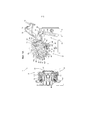
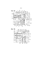
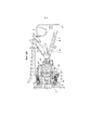
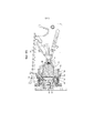
На ФИГ. 1A и 1B показаны схематические представления системы, где на ФИГ. 1A показана система, образованная устройством и первой сменной капсулой, а на ФИГ. 1B показана система, образованная устройством и второй сменной капсулой,FIG. 1A and 1B are schematic diagrams of the system, where FIG. 1A shows the system formed by the device and the first replaceable capsule, and FIG. 1B shows the system formed by the device and the second replaceable capsule,
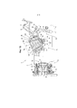
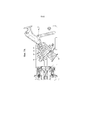
на ФИГ 2A, 2B показаны соответствующие изображения части устройства с ФИГ 1A, 1B, где на ФИГ. 2A показан вид в перспективе, а на ФИГ. 2B показан вид сбоку,FIGS. 2A, 2B show corresponding views of a portion of the device from FIGS. 1A, 1B, where FIG. 2A is a perspective view, and FIG. 2B shows a side view,
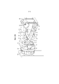
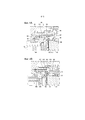
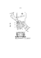
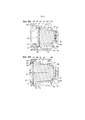
на ФИГ 3A и 3B показано функционирование блокирующего механизма устройства при взаимодействии с первой сменной капсулой, где на ФИГ. 3A показано устройство в положении готовности для первой сменной капсулы, а на ФИГ. 3D показано устройство в положении варки для первой сменной капсулы,FIGS. 3A and 3B show the operation of the locking mechanism of the device when interacting with the first replaceable capsule, where FIG. 3A shows the device in a ready position for the first refillable capsule, and FIG. 3D shows the device in the brewing position for the first replacement capsule,
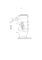
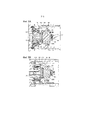
на ФИГ 4A и 4B показано функционирование блокирующего механизма устройства при взаимодействии со второй сменной капсулой, где на ФИГ. 4A показано устройство в положении готовности для второй сменной капсулы, а на ФИГ. 4B показано устройство в положении варки для второй сменной капсулы,FIGS. 4A and 4B show the operation of the locking mechanism of the device when interacting with the second replaceable capsule, where FIG. 4A shows the device in a ready position for a second refill, and FIG. 4B shows the device in brewing position for a second refillable capsule,
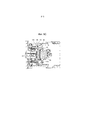
на ФИГ. 5A–5C показано функционирование захватного кольца, где на ФИГ. 5A показано захватное кольцо в положении готовности, связанное с первой сменной капсулой, на ФИГ. 5B показано захватное кольцо в промежуточном положении между положением готовности и положением варки, связанное с первой сменной капсулой, и на ФИГ. 5C показано захватное кольцо в положении варки, связанное с первой сменной капсулой,in FIG. 5A-5C show the operation of the gripping ring, where FIG. 5A shows the gripper ring in a ready position associated with the first refillable capsule in FIG. 5B shows the gripping ring in an intermediate position between the standby position and the brewing position associated with the first refillable capsule, and FIG. 5C shows the gripper ring in brewing position associated with the first replacement capsule,
на ФИГ. 6A показана первая сменная капсула в варочной камере во время экстракции,in FIG. 6A shows the first replacement capsule in the cooking chamber during extraction,
на ФИГ. 6B показана вторая сменная капсула 4B в варочной камере во время экстракции,in FIG. 6B shows the
на ФИГ 7A и 7B, соответственно, показано положение выброса первой части варочной камеры применительно к первой сменной капсуле и применительно ко второй сменной капсуле,FIGS. 7A and 7B respectively show the ejection position of the first portion of the brewing chamber in relation to the first refillable capsule and in relation to the second refillable capsule,
на ФИГ. 8A и 8B, соответственно, показан пример первой сменной капсулы и второй сменной капсулы, вставленных в варочную камеру, образованную первой частью варочной камеры и второй частью варочной камеры.in FIG. 8A and 8B, respectively, show an example of a first refillable capsule and a second refillable capsule inserted into a brewing chamber formed by a first brewing chamber portion and a second brewing chamber portion.
ПОДРОБНОЕ ОПИСАНИЕ ВАРИАНТОВ ОСУЩЕСТВЛЕНИЯDETAILED DESCRIPTION OF IMPLEMENTATION OPTIONS
На ФИГ. 1A и 1B показаны схематические виды в поперечном сечении устройства 2 для приготовления напитка. Устройство 2 выполнено с возможностью взаимодействия со сменной капсулой, например первой сменной капсулой 4A и второй сменной капсулой 4B. Устройство 2 и любая из сменной капсулы 4A и 4B образуют систему 1 для приготовления напитка. Таким образом, устройство 2 выполнено с возможностью взаимодействия и образования системы 1 с первой капсулой 4A, но также и взаимодействия и образования системы со второй сменной капсулой 4B. Устройство 2, показанное на ФИГ. 1A и 1B, является одним и тем же устройством. Устройство 2 выполнено с возможностью избирательного взаимодействия либо с первой капсулой 4A (см. ФИГ. 1A), либо со второй капсулой 4B (см. ФИГ. 1B). Следует понимать, что система 1 может включать в себя устройство 2, первую капсулу 4A и вторую капсулу 4B.FIG. 1A and 1B are schematic cross-sectional views of a
В альтернативном варианте осуществления устройство может быть выполнено с образованием системы только с одним типом сменной капсулы, например второй сменной капсулой.In an alternative embodiment, the device may be configured to form a system with only one type of refillable capsule, such as a second refillable capsule.
Первая и вторая капсулы 4A, 4B разного типа. В данном примере вторая капсула 4B больше первой капсулы 4A. Длина по оси LB второй капсулы 4B больше длины по оси LA первой капсулы 4A. Диаметр DB второй капсулы 4B больше диаметра DA первой капсулы 4A. Несмотря на эти различия, в данном примере первая и вторая капсулы 4A, 4B выполнены с возможностью создания похожего визуального впечатления. Первая и вторая капсулы 4A, 4B выполнены с возможностью оформления в стиле семейства. В данном случае соотношение длины по оси и диаметра LA/DA первой капсулы 4A по существу такое же, как и соотношение длины по оси и диаметра LB/DB второй капсулы 4B. Предпочтительно соотношение длины и диаметра первой и второй капсул идентично в пределах 20%, предпочтительно в пределах 10%, например идентично.The first and
Учитывая это подобие, обе капсулы 4A, 4B будут теперь описывать одновременно. В данном примере обе капсулы 4A, 4B имеют чашеобразный корпус 6A, 6B. При этом чашеобразный корпус 6A, 6B имеет нижнюю часть 8A, 8B и периферийную стенку 10A, 10B. Нижняя часть 8A, 8B и периферийная стенка 10A, 10B могут формировать монолитную деталь. Обе капсулы 4A, 4B включают в себя крышку 12A, 12B. Крышка 12A, 12B закрывает открытый конец чашеобразного корпуса 6A, 6B. Крышка 12A, 12B включает в себя область 13A, 13B выхода, через которую можно выпускать напиток из капсулы, как пояснено ниже. В данном примере крышку 12A, 12B соединяют с ободом 14A, 14B фланцевого типа капсулы 4A, 4B. При этом обод 14A, 14B представляет собою выступающий наружу обод. Нижняя часть 8A, 8B, периферийная стенка 10A, 10B и обод 14A, 14B могут формировать монолитную деталь. При этом область 13A, 13B выхода определяет область крышки 12A, 12B, через которую напиток может потенциально выходить из капсулы 4A, 4B. Следовательно, область крышки 12A, 12B, герметично примыкающая к ободу 14A, 14B, не составляет часть области 13A, 13B выхода. В данном примере капсулы 4A, 4B по существу вращательно–симметричные относительно оси, проходящей от нижней части 8A, 8B к крышке 12A, 12B. Чашеобразный корпус 6A, 6B и крышка 12A, 12B охватывают внутреннее пространство 16A, 16B капсулы. Внутреннее пространство 16A, 16B включает в себя некоторое количество ингредиента напитка, такого как вещество, выполненное с возможностью экстракции или выполненное с возможностью растворения. Ингредиент напитка может, например, представлять собой обжаренный и молотый кофе, чай или т. п. Ингредиент напитка может представлять собой мелкомолотый кофе. Ингредиент напитка может быть жидкостью. Учитывая разницу в размере капсул 4A, 4B, следует понимать, что вторая капсула 4B может включать в себя большее количество ингредиента напитка, чем первая капсула 4A. В данном примере внутреннее пространство 16B второй капсулы 4B приблизительно в два раза больше внутреннего пространства 16A первой капсулы 4A. Например, первая капсула 4A может включать в себя 4–8 граммов, например приблизительно 6 граммов молотого кофе. Например, вторая капсула 4B может включать в себя 8–16 граммов, например приблизительно 12 граммов молотого кофе.Given this similarity, both
Можно изготавливать чашеобразный корпус 6A, 6B из металлической фольги, такой как алюминиевая фольга, пластмассового материала, такого как полипропилен или полиэтилен, или из их комбинации. Можно изготавливать чашеобразный корпус 6A, 6B путем прессования, глубокой вытяжки, вакуумной формовки, литья под давлением или т. п. Можно изготавливать крышку из металлической фольги, такой как алюминиевая фольга, пластмассового материала, такого как полипропилен или полиэтилен, или из их комбинации. В примере капсулы 4A, 4B представляют собой так называемые закрытые капсулы. Это означает капсулы, которые являются герметично закрытыми до вставки в устройство. Устройство может открывать закрытые капсулы, как описано ниже. В альтернативном варианте осуществления также можно использовать негерметичные или заново заполняемые капсулы. Сменная капсула может иметь различные механические свойства в зависимости от материала (–ов), из которых она изготовлена, и его (их) толщины. Например, алюминиевые сменные капсулы способны относительно легко прокалываться по сравнению с полимерными сменными капсулами. С другой стороны, полимерные сменные капсулы могут быть более гибкими, что позволяет их легче размещать.The
Устройство включает в себя первую часть 18 варочной камеры и вторую часть 20 варочной камеры, выполненные с возможностью перемещения друг относительно друга. На ФИГ. 1A и ФИГ. 1B первая часть 18 варочной камеры и вторая часть 20 варочной камеры показаны в первом относительном положении. В таком первом относительном положении первая и вторая части варочной камеры образуют открытое состояние, позволяющее загружать в устройство сменную капсулу. На ФИГ. 1A в первую часть 18 варочной камеры загружена первая сменная капсула 4A. На ФИГ. 1B в первую часть 18 варочной камеры загружена вторая сменная капсула 4B. В показанном варианте осуществления каждая из частей 18, 20 варочной камеры выполнена с возможностью перемещения относительно устройства.The device includes a first
Первая и вторая части 18, 20 варочной камеры выполнены с возможностью перемещения из первого относительного положения во второе относительное положение. В этом варианте осуществления каждая из первой и второй частей 18, 20 варочной камеры принимает соответствующее положение варки во втором относительном положении, причем они являются закрытыми друг относительно друга с образованием варочной камеры 22A, 22B. Например, на ФИГ. 6A показано закрытое состояние, в котором первая и вторая части 18, 20 варочной камеры образуют варочную камеру 22A, заключающую в себе сменную капсулу 4A. На ФИГ. 6B показано закрытое состояние, в котором первая и вторая части 18, 20 варочной камеры образуют варочную камеру 22B, заключающую в себе сменную капсулу 4B.The first and
В этом варианте осуществления положение загрузки (ФИГ. 1A, 1B) первой части 18 варочной камеры отличается от положения варки (ФИГ. 6A, 6B) первой части варочной камеры тем, что в положении варки первая часть 18 варочной камеры располагается вплотную ко второй части 20 варочной камеры, тогда как в положении загрузки она располагается на расстоянии, так что полость 24 первой части 18 варочной камеры доступна для загрузки сменной капсулы. Для дополнительного упрощения загрузки в положении загрузки первая часть 18 варочной камеры повернута вместе со своей полостью 24 для доступа сверху.In this embodiment, the loading position (FIG. 1A, 1B) of the first
Положение загрузки (ФИГ. 1A, 1B) второй части 20 варочной камеры отличается от каждого из положений варки (ФИГ. 6A, 6B) второй части варочной камеры тем, что в положении варки вторая часть 20 варочной камеры располагается вплотную ко второй части 20 варочной камеры, тогда как в положении загрузки она располагается на расстоянии, так что полость 24 первой части 18 варочной камеры доступна для загрузки сменной капсулы.The loading position (FIG. 1A, 1B) of the second
В показанном варианте осуществления каждая из частей 18, 20 варочной камеры выполнена с возможностью перемещения. То есть, первая часть 18 варочной камеры выполнена с возможностью перемещения в направлении слева направо в плоскости чертежа, и дополнительно выполнена с возможностью перемещения путем поворота в плоскости чертежа. Вторая часть 20 варочной камеры выполнена с возможностью перемещения в направлении слева направо в плоскости чертежа.In the embodiment shown, each of the
В данном случае полость 24 первой части 18 варочной камеры представляет собой предварительно определенную полость 24, выполненную с возможностью удержания первой или второй капсулы 4A, 4B. В данном случае полость 24 имеет выполненную без возможности изменения форму для удержания первой или второй капсулы 4A, 4B. При этом первая часть 18 варочной камеры выполнена с возможностью удержания первой или второй капсулы 4A, 4B без изменения конфигурации первой части 18 варочной камеры. В данном примере первая часть 18 варочной камеры представляет собой монолитную деталь.In this case, the
Первая часть 18 варочной камеры имеет первый отклоняющий элемент, размещенный с возможностью отклонения капсулы 4A, 4B ко второй части 20 варочной камеры. В показанном варианте осуществления отклоняющий элемент образован спиральной пружиной 42. В альтернативном варианте осуществления отклоняющий элемент может быть выполнен в виде плоской пружины или пружины иного типа. Также может быть предусмотрен отклоняющий элемент, выполненный в виде пневматического отклоняющего элемента.The
Предусмотрен второй отклоняющий элемент, расположенный с возможностью отклонения второй части 20 варочной камеры к ее положению загрузки. В показанном варианте осуществления второй отклоняющий элемент образован спиральной пружиной 84. Спиральная пружина 84 прикладывает усилие ко второй части 20 варочной камеры, которое смещает ее к первой части 18 варочной камеры. Могут использоваться другие способы создания отклоняющего усилия, например плоская пружина или пневматический элемент.A second deflecting element is provided, which is arranged so as to deflect the
Устройство также содержит устройство выдачи текучей среды (не показано) для подачи некоторого количества текучей среды, такой как вода, под давлением к сменной капсуле, заключаемой в варочную камеру 22A, 22B. Устройство выдачи текучей среды может быть соединено с впускным отверстием варочной камеры, например впускным отверстием 47 первой части 18 варочной камеры.The device also includes a fluid dispenser (not shown) for supplying a quantity of fluid, such as water, under pressure to a replaceable capsule enclosed in the
Первая часть 18 варочной камеры включает в себя полость 24. Полость 24 размещена с возможностью приема сменной капсулы. В показанном варианте осуществления полость размещена с возможностью приема в качестве сменной капсулы одной из первой сменной капсулы 4A и второй сменной капсулы 4B. В данном примере первая часть 18 варочной камеры включает в себя первую опорную поверхность 26. Первая опорная поверхность расположена внутри полости 24. В данном случае первая опорная поверхность 26 представляет собой первую, как правило, кольцевую опорную поверхность. Первая, как правило, кольцевая опорная поверхность 26 может быть непрерывно кольцевой, или она может быть прерывистой кольцевой, например, содержащей множество сегментов вдоль кольца. Первая опорная поверхность 26 может, например, принимать форму в виде одного или более, например, дуговых ребер, которые выступают в полость 24. В данном случае первая опорная поверхность 26 обеспечивает полость 24 ступенчатой формы. В данном примере первая часть 18 варочной камеры включает в себя вторую опорную поверхность 28. Вторая опорная поверхность расположена возле открытого конца полости 24. В данном случае вторая опорная поверхность 28 является второй, как правило, кольцевой опорной поверхностью. Вторая, как правило, кольцевая опорная поверхность 28 может быть непрерывно кольцевой, или она может быть прерывистой кольцевой, например, содержащей множество сегментов вдоль кольца. Вторая опорная поверхность 28 может, например, принимать форму в виде одного или более, например, дуговых, ребер. Следует понимать, что первую опорную поверхность 26 и вторую опорную поверхность 28 располагают на расстоянии относительно друг друга в осевом направлении первой части 18 варочной камеры. Первую опорную поверхность 26 и вторую опорную поверхность 28 располагают на фиксированном расстоянии друг от друга. Первая опорная поверхность 26 и вторая опорная поверхность неподвижны относительно друг друга. При этом первая часть 18 варочной камеры включает в себя выталкиватель 38. В данном примере выталкиватель 38 включает в себя коническое кольцо 40, расположенное на конце упругого элемента 42, направленного к капсуле. Первая часть 18 варочной камеры включает в себя прокалывающее устройство 44 для прокалывания нижней части капсулы. В данном случае прокалывающее устройство включает в себя множество ножей, например три ножа. Альтернативно или дополнительно прокалывающее устройство может быть выполнено в виде одного или более сверлильных элементов.The
Как отмечалось выше, в альтернативном варианте осуществления устройство 2 может быть выполнено с возможностью взаимодействия с одним типом сменной капсулы, например только со сменной капсулой 4B. В таком альтернативном варианте осуществления достаточно лишь одной опорной поверхности, например опорной поверхности 28.As noted above, in an alternative embodiment, the
Вторая часть 20 варочной камеры включает в себя экстракционную пластину 30. Как видно лучше всего на ФИГ. 8A и 8B, в данном примере экстракционная пластина 30 включает в себя центральный участок 32 и периферийный участок 34. Центральный участок 32 выполнен с возможностью перемещения относительно периферийного участка 34. В данном случае центральный участок 32 выполнен с возможностью перемещения в осевом направлении второй части 20 варочной камеры. Экстракционная пластина 30, обеспеченная центральным участком 32 и периферийным участком 34, выполненными с возможностью перемещения друг относительно друга, дополнительно упрощает использование каждой из первой сменной капсулы 4A и второй сменной капсулы 4B, как описано ниже более подробно. Тем не менее, в других вариантах осуществления вторая часть 20 варочной камеры устройства может быть выполнена с экстракционной пластиной, имеющей только одну часть или неподвижные друг относительно друга части.The
Описанную до сих пор систему 1 можно использовать для приготовления напитка следующим образом. Попутно будут объяснены дальнейшие признаки системы 1.The
В примере, изображенном на ФИГ. 1A и 1B, устройство 2 находится в состоянии готовности к приему капсулы. На ФИГ. 1A и 1B капсулу 4A, 4B только что вставили в полость первой части 18 варочной камеры. Первая часть 18 варочной камеры находится в наклонном положении. Открытый конец полости 24 направлен вверх.In the example shown in FIG. 1A and 1B,
Как показано на ФИГ. 1A, первая капсула 4A может падать в полость 24 под действием силы тяжести. При этом обод 14A первой капсулы 4A направляется внутренней поверхностью 36 первой части 18 варочной камеры. Нижняя часть 8A первой капсулы 4A опускается в полость 24, пока она не упрется в выталкиватель 38. При этом нижняя часть 8A первой капсулы 4A центрируется на выталкивателе 38. Следует понимать, что обод 14A первой капсулы 4A располагается между первой опорной поверхностью 26 и второй опорной поверхностью 28. В этом состоянии нижнюю часть 8A первой капсулы 4A еще не прокалывают. Первая опорная поверхность 26 может отсутствовать, если устройство предназначено для использования только со второй капсулой 4B. В альтернативном варианте осуществления вторая опорная поверхность 28 может отсутствовать, если устройство предназначено для использования только с первой капсулой 4A.As shown in FIG. 1A, the
Как показано на ФИГ. 1B, вторая капсула 4B может также падать в полость 24 под действием силы тяжести. При этом периферийная стенка 10B второй капсулы 4B направляется внутренней поверхностью 46 первой части 18 варочной камеры. Нижняя часть 8B второй капсулы 4B опускается в полость 24, пока она не упрется в выталкиватель 38. При этом нижняя часть 8B второй капсулы 4B центрируется на выталкивателе 38. Следует понимать, что обод 14B второй капсулы 4B располагается ниже второй опорной поверхности 28, если смотреть со стороны прокалывающего устройства 44. В этом состоянии нижнюю часть 8B второй капсулы 4B еще не прокалывают.As shown in FIG. 1B, the
После вставки капсулы 4A, 4B в полость 24, как показано на ФИГ. 1A и 1B, можно перемещать первую часть 18 варочной камеры ко второй части 20 варочной камеры для смыкания варочной камеры вокруг капсулы 4A, 4B. Первую часть 18 варочной камеры направляют в раму 48 устройства.Upon insertion of
В данном примере первая часть 18 варочной камеры включает в себя первые выступы 50 и вторые выступы 52, как показано на ФИГ. 2A и 2B. Первые выступы 50 направляют в первую канавку 54 рамы 48. Вторые выступы 52 направляют во вторую канавку 56 рамы 48. Следует понимать, что выступы 50, 52 и канавки 54, 56 определяют траекторию, по которой будет следовать первая часть 18 варочной камеры. В данном случае в боковой стенке 57 рамы 48 обеспечивают первую канавку 54 и вторую канавку 56. Первая канавка 54 проходит в боковую стенку 57 на первую глубину. Вторая канавка 56 проходит в боковую стенку на вторую глубину. Вторая глубина больше первой глубины. Диаметр первого выступа 50 больше диаметра второго выступа 52. Ширина первой канавки 54 больше ширины второй канавки 56. Ширина первой канавки 54 соответствует диаметру первого выступа 50. Ширина второй канавки 56 соответствует ширине второго выступа 52. Следует понимать, что первая канавка 54 проходит по траектории, отличающейся от траектории второй канавки 56. Различные ширины и глубины канавок позволяют первому и второму выступам 50, 52 двигаться по разным траекториям. Данная конструкция обеспечивает очень компактную конструкцию для направления первого и второго выступов 50, 52.In this example, the
Устройство 2 включает в себя рычаг 58. Пользователь может вручную приводить в действие рычаг. Рычаг с возможностью поворота соединяют с рамой 48 вокруг оси 60 рычага. Первую часть 18 варочной камеры соединяют с рамой 48 посредством коленчатого шарнира 62. Коленчатый шарнир 62 включает в себя шток 64 толкателя и кривошип 66. Шток 64 толкателя с возможностью поворота соединяют с кривошипом 66 на оси 68 колена. Кривошип 66 с возможностью поворота соединяют с рамой 48 на оси 70 кривошипа. Рычаг 58 соединяют с коленчатым шарниром 62 для приведения в движение первой части 18 варочной камеры. В данном случае рычаг 58 соединяют с коленчатым шарниром 62 посредством звена 74 рычага. Звено 74 рычага с возможностью поворота соединяют с рычагом 58 на оси 76 звена рычага. Звено 74 рычага с возможностью поворота соединяют со штоком 74 толкателя на оси 78 звена колена.The
Захватное кольцо 80 выполнено с возможностью окружения первой части 18 варочной камеры. Как видно более детально на ФИГ 5А–5С, захватное кольцо 80 выполнено с возможностью перемещения в осевом направлении относительно первой части 18 варочной камеры. В данном случае захватное кольцо 80 направляется внешней поверхностью первой части 18 варочной камеры. Захватное кольцо соединяют с первой частью варочной камеры посредством одного или более упругих элементов 82, в данном случае спиральных пружин. Шток толкателя с возможностью поворота соединяют с захватным кольцом 80 на оси 72 штока толкателя. Следовательно, в данном случае коленчатый шарнир 62 косвенно соединяют с первой частью 18 варочной камеры, т. е. посредством захватного кольца 80 и одного или более упругих элементов 82. Функция захватного кольца будет описана ниже.The gripping
При перемещении рычага 58 в нижнем направлении коленчатый шарнир 62 будет толкать первую часть 18 варочной камеры ко второй части 20 варочной камеры. Одновременно за счет формы первой и второй канавок 54, 56 будут поворачивать первую часть 18 варочной камеры из наклонной ориентации вверх в совмещенную ориентацию, в которой осевое направление первой части 18 варочной камеры совмещают с осевым направлением второй части 20 варочной камеры.When the
Как упоминалось выше, устройство 2 выполнено с возможностью выборочного взаимодействия либо с первой капсулой 4A, либо со второй капсулой 4B. В данном случае система 1 выполнена с возможностью автоматической регулировки варочной камеры в зависимости от того, вставлена ли первая или вторая капсула. Это обеспечивает преимущество, заключающееся в отсутствии пользовательского ввода для выбора правильной обработки первой или второй капсулы. Следовательно, значительно снижают риск ошибки.As mentioned above, the
Как упоминалось выше, в частности применительно к ФИГ. 1A, 1B и ФИГ. 8A, 8B, вторая часть 20 варочной камеры включает в себя экстракционную пластину 30 с центральным участком 32 и периферийным участком 34. В данном случае центральный участок 32 выполнен с возможностью перемещения в осевом направлении второй части 20 варочной камеры. Центральный участок 32 в данном примере включает в себя вал 32’, выполненный с возможностью осевого скользящего перемещения относительно рамы 48. Центральный участок 32 соединяют с рамой 48 посредством отклоняющего элемента, выполненного в виде упругого элемента 84, в данном случае спиральной пружины. Упругий элемент 84 смещает центральный участок в положение готовности, изображенное на ФИГ. 1A и 1B. Альтернативно или дополнительно могут быть предусмотрены один или более других отклоняющих элементов, например упругий элемент, тянущий центральный участок к его положению готовности. В данном примере положение готовности представляет собой выдвинутое положение. Это положение загрузки второй части варочной камеры. Можно располагать центральный участок 32 в первое положение варки для взаимодействия с первой капсулой 4A. Можно располагать центральный участок во второе положение варки для взаимодействия со второй капсулой 4B. В данном примере система 1 включает в себя блокирующий механизм 86, выполненный с возможностью блокировки центрального участка 32 в первом положении варки или возле него, когда полость 24 удерживает первую капсулу 4A. Отклоняющий элемент, например упругий элемент 84, имеет меньшую жесткость, чем отклоняющий элемент (например, упругий элемент 42), который отклоняет капсулу ко второй части варочной камеры. Соответственно, в положении готовности область 12A, 12B выхода капсулы 4A, 4B упирается в экстракционную пластину 30, но отклоняющий элемент, который отклоняет капсулу ко второй части варочной камеры, не дает прокалывающему элементу 44 на этой стадии проколоть нижнюю часть 8A, 8B капсулы. Этого можно добиться, например, в результате того, что упругий элемент 42 удерживает нижнюю часть 8A, 8B капсулы на расстоянии от прокалывающего элемента 44 или, например, в результате того, что упругий элемент 42 помогает капсуле выдержать усилие, создаваемое прокалывающим элементом 44. Таким образом, в данном случае, благодаря полной упругости, обеспечиваемой упругим элементом или другим отклоняющим элементом, а также упругости нижней части капсулы, откладывается прокалывание капсулы до тех пор, пока система из устройства и капсулы не достигнет положения готовности. Для обеспечения воспроизводимой работы, совокупная упругость по меньшей мере упругой капсулы и отдельного упругого элемента или иного элемента устройства, создающего отклоняющее усилие, должна превышать упругость отклоняющего элемента, который отклоняет вторую часть 20 варочной камеры в положение готовности.As mentioned above, in particular in relation to FIG. 1A, 1B and FIG. 8A, 8B, the second
При дальнейшем смещении к положению варки, экстракционная пластина 30 или центральный участок 32 блокируются, по существу завершая динамический диапазон второго отклоняющего элемента, например упругого элемента 84. С этого момента и далее отклоняющий элемент, например упругий элемент 42 или иные средства отклонения, возможно в сочетании с упругостью капсулы, более не могут сопротивляться усилию, создаваемому экстракционной пластиной 30 или ее частью на область 12A, 12B выхода капсулы. В результате нижняя часть 8A, 8B капсулы прокалывается прокалывающим элементом 44, так что устройство выдачи текучей среды может подавать некоторое количество текучей среды, такой как вода, под давлением к сменной капсуле.Upon further displacement towards the cooking position, the
Следует отметить, что не обязательно обеспечивать отдельный элемент для формирования конечной точки динамического диапазона второго отклоняющего элемента. Второй отклоняющий элемент, например упругий элемент 84, может иметь внутреннюю конечную точку динамического диапазона, соответствующую динамическому диапазону, который требуется для работы устройства. Например, упругий элемент 84 может быть в полностью сжатом состоянии в положении готовности, показанном на ФИГ. 3A или ФИГ. 4A, так что дальнейшее продвижение корпуса 94 к первой части 18 варочной камеры приводит к тому, что первый отклоняющий элемент, например упругий элемент 42, отступает, позволяя проколоть нижнюю часть 8A, 8B капсулы.It should be noted that it is not necessary to provide a separate element to form the end point of the dynamic range of the second deflector. The second deflector, such as
Следует отметить, что в вариантах осуществления, предназначенных для использования только с одним типом сменной капсулы, будет достаточно, если вторая часть варочной камеры будет иметь только одно положение варки в дополнение к положению загрузки/положению готовности. Как указано выше, будет достаточно, если экстракционная пластина 30 будет иметь только один участок или участки, неподвижные относительно друг друга. Также в вариантах осуществления, предназначенных для работы только с одним типом капсул, блокирующий механизм будет избыточным. Пример блокирующего механизма для упрощения взаимодействия устройства 2 с разными типами сменных капсул описывается ниже с отсылкой к ФИГ. 3A, 3B и ФИГ. 4A, 4B.It should be noted that in embodiments intended for use with only one type of refillable capsule, it will be sufficient if the second part of the brewing chamber has only one brewing position in addition to the loading / ready position. As indicated above, it will be sufficient if the
Таким образом, блокирующий механизм 86 включает в себя фиксатор 88. В данном случае фиксатор 88 выполняют в виде поворотного пальца, выполненного с возможностью поворота вокруг оси 90 вращения. Фиксатор 88 смещают в положение, отвернутое в сторону от вала 32’. Фиксатор можно также смещать в любое другое подходящее положение. Блокирующий механизм 86 дополнительно включает в себя толкатель 92. Толкатель направляют с возможностью скольжения в корпус 94 второй части 20 варочной камеры. Толкатель 92 соединен с корпусом 94 посредством упругого элемента 96, в данном случае спиральной пружины. Упругий элемент 96 смещает толкатель в выдвинутое положение. Первая часть 18 варочной камеры включает в себя исполнительный механизм 98. В данном случае исполнительный механизм образован фронтальной поверхностью первой части 18 варочной камеры.Thus, the
На ФИГ. 3A и 3B показано функционирование блокирующего механизма 86, когда полость 24 удерживает первую капсулу 4A. В данном примере наиболее удаленную от центра часть первой капсулы 4A, сформированную здесь крышкой 12A, областью 13A выхода и/или ободом 14A, располагают ближе к задней части, т. е. больше к прокалывающему устройству 44, относительно исполнительного механизма 98. В результате при продвижении первой капсулы 4A ко второй части 20 варочной камеры исполнительный механизм 98 коснется толкателя 92 прежде, чем наиболее удаленная от центра часть первой капсулы 4A коснется центрального участка 32. Толкатель отталкивается отклоняющим усилием упругого элемента 96. Буртик 100 толкателя 92 будет скользить вдоль наклонной поверхности 102 фиксатора 88, за счет чего фиксатор 88 будет поворачиваться к валу 32’. В результате выступ 104 фиксатора 88 размещают на траектории перемещения части 106 центрального участка 32 (см. ФИГ. 3B). При дополнительном продвижении первой капсулы 4A ко второй части 20 варочной камеры первая капсула 4A упрется в центральный участок 32. (ФИГ. 3A) За счет этого отклоняющее усилие упругого элемента 84 отклонит центральный участок. Повернутый фиксатор 88 предотвращает перемещение центрального участка дальше положения, в котором часть 106 упирается в выступ 104. В настоящем документе это определяют как первое положение варки. Таким образом, первая капсула 4A выполнена с возможностью перемещения центрального участка 32 из положения готовности (ФИГ. 3A) в первое положение варки (ФИГ. 3B). Во время варки первую капсулу 4A удерживают между первой и второй частями 18, 20 варочной камеры, причем центральный участок 32 находится в первом положении варки.FIG. 3A and 3B show the operation of the
На ФИГ. 4A и 4B показано функционирование блокирующего механизма 86, когда полость 24 удерживает вторую капсулу 4B. В данном примере наиболее удаленную от центра часть второй капсулы 4B, сформированную здесь крышкой 12B, областью 13B выхода и/или ободом 14B, располагают ближе к передней части, т. е. больше ко второй части 20 варочной камеры, относительно исполнительного механизма 98. В результате при продвижении второй капсулы 4B ко второй части 20 варочной камеры наиболее удаленная от центра часть второй капсулы 4B упрется в центральный участок 32 прежде, чем исполнительный механизм 98 коснется толкателя 92. Центральный участок 32 отталкивается отклоняющим усилием упругого элемента 84, при этом фиксатор 88 все еще отвернут в сторону от вала 32’. В результате часть 106 проходит под выступом 104. Только после прохождения части 106 мимо выступа 104 толкатель отталкивается отклоняющим усилием упругого элемента 96 с помощью исполнительного механизма 98. Буртик 100 толкателя 92 будет по–прежнему скользить вдоль наклонной поверхности 102 фиксатора 88, за счет чего фиксатор 88 будет поворачиваться к валу 32’. Однако часть 106 в этот момент уже прошла мимо выступа 104 и в данном примере вторая капсула 4B толкает центральный участок 32, упирая его в корпус 94. В настоящем документе это определяют как второе положение варки. Таким образом, вторая капсула 4B выполнена с возможностью перемещения центрального участка 32 из положения готовности во второе положение варки. Во время варки вторую капсулу 4B удерживают между первой и второй частями 18, 20 варочной камеры, причем центральный участок 32 находится во втором положении варки.FIG. 4A and 4B show the operation of the
Таким образом, блокирующий механизм 86 выполнен с возможностью блокировки центрального участка 32 в первом положении экстракции или возле него, когда полость 24 удерживает первую капсулу 4A. Как отмечалось, блокировка может быть односторонней, т. е. блокирующий механизм может предотвращать перемещение центрального участка 32 дальше первого положения экстракции, когда полость 24 удерживает капсулу 4A. Однако это не может предотвращать перемещение центрального участка 32 из первого положения экстракции в положение готовности. Блокирующий механизм 86 выполнен с возможностью выборочного предотвращения блокировки центрального участка 32 в первом положении варки или возле него, когда вторую капсулу 4B включают в варочную камеру. Блокирующий механизм 86 выполнен с возможностью выборочного обеспечения перемещения центрального участка 32 во второе положение варки или возле него, когда вторую капсулу вставляют в варочную камеру.Thus, the
При сравнении ФИГ. 3A и 4A следует понимать, что при продвижении первой части 18 варочной камеры ко второй части 20 варочной камеры первую капсулу 4A отводят дальше вглубь первой части варочной камеры по сравнению со второй капсулой 4B. Кроме того, первую крышку 12A, область 13A выхода и/или обод 14A отводят дальше вглубь первой части 18 варочной камеры по сравнению со второй крышкой 12B, областью 13B выхода и/или ободом 14B.When comparing FIG. 3A and 4A, it should be understood that as the first
При сравнении ФИГ. 3B и 4B следует понимать, что когда варочная камера удерживает первую капсулу 4A, центральный участок 32 проходит в полость 24. Центральный участок 32 проходит в первую часть 18 варочной камеры дальше положения, в котором находились бы крышка 12B, область 13B выхода и/или обод 14B второй капсулы 4B, если бы вторую капсулу вставили в первую часть 18 варочной камеры.When comparing FIG. 3B and 4B, it should be understood that when the brewing chamber is holding the
Как упоминалось выше, коленчатый шарнир 62 косвенно соединяют с первой частью 18 варочной камеры, т. е. посредством захватного кольца 80 и одного или более упругих элементов 82. На ФИГ. 5A–5C показано функционирование захватного кольца 80.As mentioned above, the articulation joint 62 is indirectly connected to the
На ФИГ. 5A первая капсула 4A упирается в центральный участок 32, когда центральный участок находится в своем первом положении варки. Первая часть 18 варочной камеры находится в промежуточном положении между положением загрузки и положением варки. Первый отклоняющий элемент 42 первой части варочной камеры отклоняет капсулу 4A ко второй части 32 варочной камеры, тем самым не давая прокалывающему элементу 44 на этой стадии проколоть нижнюю часть 8A капсулы 4A.FIG. 5A, the
Захватное кольцо 80 все еще находится в заднем положении. Следует понимать, что рычаг 58 еще не достигнет своего конечного положения. Первая часть 18 варочной камеры включает в себя выступ 108. В данном случае выступ 108 представляет собой по существу кольцевой выступ. Выступ 108 выходит наружу. При этом выступ 108 формирует наиболее удаленный от центра край первой части 18 варочной камеры. Вторая часть 20 варочной камеры включает в себя удерживающее устройство 110. В данном случае удерживающее устройство 110 выполнено в виде окружного кольца из захватных буртиков. Удерживающее устройство 110 с возможностью поворота соединяют с корпусом 94. В данном случае удерживающее устройство 110 упруго с возможностью поворота соединяют с корпусом 94. Удерживающее устройство 110 включает в себя зубец 112. В данном случае зубец имеет первую наклонную поверхность 114 и вторую наклонную поверхность 116.The
При опускании рычага 58 захватное кольцо 80 будут продвигать ко второй части 20 варочной камеры. Один или более упругих элементов 82 будут толкать первую часть 18 варочной камеры перед захватным кольцом 80, пока первая часть варочной камеры не достигнет положения варки и не упрется во вторую часть 20 варочной камеры, например, с зажатием между ними капсулы 4A, 4B. За счет этого удерживающее устройство 110 поворачивается к наружной стороне (см. ФИГ. 5A). Во время этого перемещения первой части 18 варочной камеры выступ 108 будет продвигаться на уровне первой наклонной поверхности 114.When the
На этой стадии усилие, создаваемое второй частью 20 варочной камеры, превышает отклоняющее усилие, создаваемое упругим элементом 42. Вследствие этого прокалывающее устройство 44 входит в нижнюю часть 8A капсулы 4A, тем самым обеспечивая доступ для подачи некоторого количества текучей среды, такой как вода, под давлением к сменной капсуле. В то же время капсула 4A вводится в полость. Дальнейшее продвижение приводит к тому, что выступ 108 проходит за вторую наклонную поверхность 116, заставляя удерживающее устройство 110 повернуться внутрь (см. ФИГ. 5B). За счет дополнительного опускания рычага 58 первая часть варочной камеры упрется во вторую часть 20 варочной камеры, что приведет к сжатию одного или более упругих элементов 82. В результате захватное кольцо 80 продвинется ко второй части 20 варочной камеры. За счет полного опускания рычага 58 захватное кольцо 80 разместится между удерживающим устройством 110 и запорным кольцом 118 (см. ФИГ. 5C). Захватное кольцо 80, окружающее удерживающее устройство 110, предотвращает поворот захватного устройства 110 к наружной стороне. Таким образом, первую часть варочной камеры блокируют относительно второй части 20 варочной камеры. Первую часть варочной камеры блокируют на второй части 20 варочной камеры.At this stage, the force exerted by the second
Устройство может включать в себя систему подачи текучей среды для подачи текучей среды, например жидкости, такой как горячая вода под давлением, в первую часть 18 варочной камеры. Когда варочная камера находится под давлением текучей среды для варки напитка, первая и вторая части 18, 20 варочной камеры будут отталкиваться друг от друга давлением текучей среды. Удерживающее устройство 110 и захватное кольцо 80, а также необязательно запорное кольцо 118 будут выдерживать полностью или частично усилие, созданное давлением текучей среды. Захватное кольцо 80, размещенное между удерживающим устройством 110 и запорным кольцом 118, повышает механическую устойчивость. Захватное кольцо 80 не должно выдерживать все усилия, оказанные на него удерживающим устройством 110, так как оно может упираться в запорное кольцо 118 и передавать по меньшей мере часть усилий на запорное кольцо 118. Запорное кольцо 118 может быть неподвижным, и, следовательно, его можно без труда усиливать. Так как первую часть варочной камеры блокируют на второй части 20 варочной камеры, рама 48 и исполнительный механизм, например коленчатый шарнир, не должны выдерживать это усилие или по меньшей мере его меньшую часть. Следовательно, можно проектировать более слабые и/или более дешевые раму и/или исполнительный механизм.The apparatus may include a fluid supply system for supplying a fluid, such as a liquid, such as pressurized hot water, to the
Хотя функционирование захватного кольца 80 показано на ФИГ. 5A–5C в отношении первой капсулы 4A, следует понимать, что захватное кольцо 80 может функционировать идентично в отношении второй капсулы 4B. На ФИГ. 6A показана первая капсула 4A в варочной камере во время экстракции. На ФИГ. 6B показана вторая капсула 4B в варочной камере во время экстракции.Although the operation of the
Прокалывающий элемент 44 выполнен с возможностью прокалывания нижней части 8A, 8B капсулы 4A, 4B. Как также можно заметить на ФИГ. 5A–5C, в данном примере прокалывающий элемент 44 не прокалывает нижнюю часть 8A, 8B, пока крышка 12A, 12B капсулы 4A, 4B не упрется в центральный участок 32 в первом или во втором положении варки. Для этой цели можно выбирать жесткость упругого элемента 42 и упругого элемента 84. В данном примере жесткость упругого элемента 42 выбирают так, чтобы она была больше жесткости упругого элемента 84.The piercing
После включения капсулы 4A, 4B в варочную камеру и прокалывания нижней части 8A, 8B текучую среду, в данном примере горячую воду под давлением, можно подавать в варочную камеру. Поэтому желательно, чтобы варочная камера была герметичной. Для этой цели центральный участок 32 обеспечивают первым уплотнительным элементом 120. Периферийный участок 34 обеспечивают вторым уплотнительным элементом 122. Устройство 2 для приготовления напитка выполнено с возможностью приготовления количества напитка, пригодного для употребления, с использованием либо первой капсулы 4A, либо второй капсулы 4B. Количество может быть предварительно заданным количеством. Количество может также быть количеством, выполненным с возможностью выбора, установки или программирования пользователем.After inserting the
На ФИГ. 3B описывается уплотнение с учетом первой капсулы 4A. Первый уплотнительный элемент 120 выполнен с возможностью обеспечения герметичного для текучей среды сцепления между центральным участком 32 и первой частью 18 варочной камеры при формировании варочной камеры для удержания первой капсулы 4A. В данном примере первый уплотнительный элемент 120 упирается в первую часть 18 варочной камеры, когда первую капсулу 4A помещают в варочную камеру. Это обеспечивает уплотнение для воды, присутствующей в полости 24 снаружи капсулы 4A. Таким образом предотвращают обход варочной текучей среды, поданной в варочную камеру 22A, вокруг наружной части капсулы 4A. В примере, изображенном на ФИГ. 3B, первый уплотнительный элемент 120 включает в себя упругий буртик 121. Упругий буртик 121 выполнен с возможностью обеспечения самоусиливающегося герметичного сцепления между центральным участком 32 и первой частью 18 варочной камеры под действием давления текучей среды в варочной камере. В данном примере первый уплотнительный элемент 120 упирается в обод 14A первой капсулы 4A. Обод 14A прижимается к первому уплотнительному элементу 120 первой опорной поверхностью 26. Это обеспечивает герметичное сцепление между центральным участком 32 и капсулой 4A, препятствующее выходу напитка из капсулы 4A через область 13A выхода. Следует понимать, что в данном случае боковая сторона обода 14A, направленная от чашеобразного корпуса 6A, герметично примыкает ко второй части 20 варочной камеры. Альтернативно или дополнительно боковая сторона обода 14A, направленная к чашеобразному корпусу 6A, может герметично примыкать к первой части 18 варочной камеры. С этой целью можно обеспечивать дополнительное уплотнение на первой части 18 варочной камеры, например на первой опорной поверхности 26, и/или на капсуле 4A, например на ободе 14A. Понятно, что уплотнение на капсуле может быть дополнительным к уплотнению между первой частью 18 варочной камеры и второй частью 20 варочной камеры. За счет этого можно снижать герметизирующее действие первого уплотнительного элемента 120.FIG. 3B describes the seal in view of the
На ФИГ. 4B описывается уплотнение с учетом второй капсулы 4B. Второй уплотнительный элемент 122 выполнен с возможностью обеспечения герметичного для текучей среды сцепления между периферийным участком 34 и первой частью 18 варочной камеры при формировании варочной камеры для удержания второй капсулы 4B. В данном примере второй уплотнительный элемент 122 упирается в первую часть 18 варочной камеры, когда вторую капсулу 4B включают в варочную камеру. Это обеспечивает уплотнение для воды, присутствующей в полости 24 снаружи капсулы 4B. В примере, изображенном на ФИГ. 4B, второй уплотнительный элемент 122 имеет упругий буртик 123. Упругий буртик 123 выполнен с возможностью обеспечения самоусиливающегося герметичного сцепления между периферийным участком 34 и первой частью 18 варочной камеры под действием давления текучей среды в варочной камере. В данном примере второй уплотнительный элемент 122 упирается в обод 14B второй капсулы 4B. Обод 14B прижимают ко второму уплотнительному элементу 122 второй опорной поверхностью 28. Это может обеспечивать герметичное сцепление между периферийным участком 34 и капсулой 4B, препятствующее выходу напитка из капсулы 4B через область 13B выхода. На ФИГ. 4B первый уплотнительный элемент 120 обеспечивает герметичное сцепление между центральным участком 32 и периферийным участком 34 при образовании варочной камеры для удержания второй капсулы 4B. Герметичное сцепление между центральным участком 32 и периферийным участком 34 может быть самоусиливающимся. С этой целью сцепление между периферийным участком 34 и второй капсулой 4B может допускать пропускание варочной текучей среды к первому уплотнительному элементу 120. Таким образом, первый уплотнительный элемент 120 обеспечивает герметичное сцепление между центральным участком 32 и капсулой 4B, препятствующее выходу напитка из капсулы 4B через область 13B выхода. Следует понимать, что в данном случае боковую сторону обода 14B, направленную от чашеобразного корпуса 6B, причем обод может быть покрыт или не покрыт крышкой, например фольгой, могут герметично примыкать ко второй части 20 варочной камеры. Альтернативно или дополнительно боковая сторона обода 14B, направленная к чашеобразному корпусу 6B, может герметично примыкать к первой части 18 варочной камеры. С этой целью можно обеспечивать дополнительное уплотнение на первой части 18 варочной камеры, например на второй опорной поверхности 28, и/или на капсуле 4B, например на ободе 14B. Понятно, что уплотнение на капсуле может быть дополнительным к уплотнению между первой частью 18 варочной камеры и второй частью 20 варочной камеры. За счет этого можно снижать герметизирующее действие второго уплотнительного элемента 122.FIG. 4B describes the seal in view of the
Когда текучую среду под давлением подают в капсулу 4A, 4B в варочной камере, область 13A, 13B выхода может открываться к экстракционной пластине 30. Экстракционная пластина 30 в данном примере включает в себя множество рельефных элементов 124. В данном случае рельефные элементы 124 представляют собой усеченные пирамиды. Повышение давления внутри капсулы 4A, 4B может приводить к разрыву области 13A, 13B выхода рельефными элементами, что позволит напитку выходить из капсулы 4A, 4B.When pressurized fluid is fed into the
Напиток может проходить сквозь экстракционную пластину 30 через отверстия в экстракционной пластине. Далее напиток может протекать к выпускному отверстию 126. Из выпускного отверстия 126 напиток может протекать в приемный сосуд, такой как чашка.The beverage can pass through the
В предыдущих разделах описаны аспекты, упрощающие работу устройства 2 с любой из первой сменной капсулы 4A и второй сменной капсулы 4B. Возможны другие варианты осуществления, в которых устройство 2 особенно хорошо подходит для работы с первой сменной капсулой 4A или особенно хорошо подходит для работы со второй сменной капсулой 4B.In the previous sections, aspects have been described to facilitate the operation of the
В устройстве 2, которое особенно хорошо подходит для работы с первой сменной капсулой 4A, можно рассмотреть возможность исключения одного или более из следующих элементов: вторая опорная поверхность 28, периферийный участок 34 экстракционной пластины 30, фиксатор 88, толкатель 92, упругий элемент 96, исполнительный механизм 98.In
В устройстве 2, которое особенно хорошо подходит для работы со второй сменной капсулой 4B, можно рассмотреть возможность исключения одного или более из следующих элементов: первая опорная поверхность 26, фиксатор 88, толкатель 92, упругий элемент 96, исполнительный механизм 98. Экстракционная пластина 30 может быть выполнена как одна деталь или как жестко соединенные друг с другом центральный участок и периферийный участок.In
После варки напитка рычаг 58 можно перемещать вверх. Это приведет к удалению захватного кольца 80 из удерживающего устройства 110. Далее первую часть 18 варочной камеры будут перемещать в заднем направлении. Вторая наклонная поверхность 116 удерживающего устройства 110 может позволять удерживающему устройству миновать выступ 108. Первая часть 18 варочной камеры будет отходить от второй части 20 варочной камеры. Центральный участок 32 будет возвращаться в положение готовности. Выступы 50, 52 и канавки 54, 56 определяют траекторию, по которой будет следовать первая часть 18 варочной камеры. Как показано на ФИГ. 7A и 7B, первая часть варочной камеры повернется вниз. Это способствует выбросу использованной капсулы 4A, 4B из полости 24 под действием силы тяжести. Выталкиватель 38 может помочь в выталкивании капсулы 4A, 4B с прокалывающего элемента 44 и из полости 24. Использованные капсулы 4A, 4B могут падать в корзину для отходов устройства 2.After brewing the beverage, the
В данном примере первая и вторая капсулы 4A, 4B выполнены с возможностью создания похожего визуального впечатления. На ФИГ. 8A показан пример первой капсулы 4A, вставленной в варочную камеру 22A, сформированную первой частью 18 варочной камеры и второй частью 20 варочной камеры. Следует понимать, что периферийная стенка 10A уже, чем полость 24, в этом месте. В результате имеется первый объем 126, окружающий первую капсулу 4A внутри полости 24. На ФИГ. 8B показан пример второй капсулы 4B, вставленной в варочную камеру 22B, сформированную первой частью 18 варочной камеры и второй частью 20 варочной камеры. Следует понимать, что часть 128 периферийной стенки 10B уже, чем полость 24, в этом месте. Эта часть 128 образована частью периферической стенки 10B, проходящей за первую опорную поверхность 26. В результате имеется второй объем 130, окружающий вторую капсулу 4B внутри полости 24.In this example, the first and
Отмечено, что первый объем 126 не занят первой капсулой 4A, когда варочная камера удерживает первую капсулу 4A. Однако этот первый объем 126 занят частью второй капсулы 4B, когда варочная камера удерживает вторую капсулу 4B. Второй объем 130 не занят второй капсулой 4B, когда варочная камера удерживает вторую капсулу 4B. Этот второй объем 130 принимает центральный участок 32 экстракционной пластины 30, когда варочная камера удерживает первую капсулу 4A.It is noted that the
Когда при варке напитка используют первую капсулу 4A, первый объем 126 будет заполняться текучей средой, такой как вода, причем эту текучую среду не используют для варки напитка. После варки эту текучую среду можно сливать в корзину для отходов. Когда при варке напитка используют вторую капсулу 4A, второй объем 130 будет заполняться текучей средой, такой как вода, причем эту текучую среду не используют для варки напитка. После варки эту текучую среду можно сливать в контейнер, например в корзину для отходов. В данном примере первый объем 126 по существу равен второму объему 130. Следовательно, объем текучей среды, направленный в корзину для отходов, по существу одинаковый при варке напитка с использованием первой капсулы 4A и при варке напитка с использованием второй капсулы 4B.When the
В настоящем документе изобретение описывают со ссылкой на конкретные примеры вариантов осуществления изобретения. Однако следует понимать, что в эти примеры можно вносить различные модификации и изменения без отступления от сущности изобретения. Для ясности и краткости описания в настоящем документе признаки описывают в рамках одного и того же или отдельных вариантов осуществления, однако альтернативные варианты осуществления, имеющие комбинации всех или некоторых из признаков, описанных в этих отдельных вариантах осуществления, тоже предусмотрены.In this document, the invention is described with reference to specific examples of embodiments of the invention. However, it should be understood that various modifications and changes can be made to these examples without departing from the spirit of the invention. For clarity and brevity of description herein, features are described within the same or separate embodiments, however, alternative embodiments having combinations of all or some of the features described in these separate embodiments are also contemplated.
В этих примерах центральный участок экстракционной пластины включает в себя множество рельефных элементов. Периферийный участок не включает в себя рельефные элементы. Однако следует понимать, что периферийный участок тоже может включать в себя рельефные элементы. Можно адаптировать экстракционную пластину и вторую область выхода друг к другу таким образом, чтобы гидравлическое сопротивление второй области выхода, когда она открыта, было меньше гидравлического сопротивления первой области выхода, когда она открыта. Можно адаптировать экстракционную пластину и вторую область выхода друг к другу таким образом, чтобы вторая область выхода разрывалась на экстракционной пластине на большей площади поверхности, чем первая область выхода. Можно адаптировать экстракционную пластину и вторую область выхода друг к другу таким образом, чтобы вторая область выхода разрывалась на экстракционной пластине в большем количестве мест, чем первая область выхода. Наружные рельефные элементы могут быть выполнены с возможностью разрыва как первой, так и второй области выхода, причем вторая область выхода разрывается на наружных рельефных элементах на большей площади поверхности, чем первая область выхода. Экстракционная пластина может включать в себя рельефные элементы первого типа и по меньшей мере один рельефный элемент второго типа, причем рельефные элементы первого типа выполнены в пределах области, соответствующей первой области выхода, и при этом по меньшей мере один рельефный элемент второго типа выполнен в пределах области, соответствующей второй области выхода, и за пределами области, соответствующей первой области выхода. Рельефный элемент второго типа может иметь более острый край, чем рельефные элементы первого типа. Вторая область выхода может включать в себя ослабленную зону. Ослабленную зону можно располагать в периферийной области второй области выхода.In these examples, the center portion of the extraction plate includes a plurality of relief elements. The peripheral section does not include relief elements. However, it should be understood that the peripheral portion may also include relief elements. It is possible to adapt the extraction plate and the second outlet area to each other so that the hydraulic resistance of the second outlet area when it is open is less than the hydraulic resistance of the first outlet area when it is open. It is possible to adapt the extraction plate and the second exit region to each other so that the second exit region breaks on the extraction plate over a larger surface area than the first exit region. It is possible to adapt the extraction plate and the second exit area to each other so that the second exit area breaks on the extraction plate in more places than the first exit area. The outer relief elements can be configured to rupture both the first and the second exit region, with the second exit region breaking at the outer relief elements over a larger surface area than the first exit region. The extraction plate may include relief elements of the first type and at least one relief element of the second type, wherein the relief elements of the first type are made within the region corresponding to the first exit region, and wherein at least one relief element of the second type is made within the region corresponding to the second exit area, and outside the area corresponding to the first exit area. The second type of relief may have a sharper edge than the first type of relief. The second exit area may include a weakened zone. The weakened zone can be located in the peripheral region of the second exit region.
В примерах первая и вторая капсулы имеют по существу одинаковую форму. Можно также обеспечивать третью капсулу, имеющую другую форму. Третья капсула может, например, быть выполнена в такой форме, чтобы по существу заполнять варочную камеру, когда центральный участок находится в первом положении экстракции. Можно также обеспечивать четвертую капсулу, имеющую другую форму. Четвертая капсула может, например, быть выполнена в такой форме, чтобы по существу заполнять варочную камеру, когда центральный участок находится во втором положении экстракции.In the examples, the first and second capsules have substantially the same shape. You can also provide a third capsule with a different shape. The third capsule may, for example, be shaped to substantially fill the cooking chamber when the center portion is in the first extraction position. It is also possible to provide a fourth capsule having a different shape. The fourth capsule may, for example, be shaped to substantially fill the cooking chamber when the center portion is in the second extraction position.
В примерах первая капсула имеет выступающий наружу обод фланцевого типа. Следует понимать, что первая капсула может не иметь выступающего наружу обода. В примерах вторая капсула имеет выступающий наружу обод фланцевого типа. Следует понимать, что вторая капсула может не иметь выступающего наружу обода.In the examples, the first capsule has a flange type outwardly projecting rim. It should be understood that the first capsule may not have an outwardly projecting rim. In the examples, the second capsule has a flange-type outwardly projecting rim. It should be understood that the second capsule may not have an outwardly projecting rim.
В примерах корпус и крышку капсулы изготавливают из алюминиевой фольги, предпочтительно из полимера, имеющего покрытие из алюминиевой фольги, чтобы обеспечивать легкое приваривание крышки к корпусу. Следует понимать, что можно изготавливать корпус и/или крышку капсулы из самых разных материалов, которые пригодны, по мнению специалистов в данной области, и выполнены с возможностью переработки в лист, пленку или фольгу с помощью методов, обычно принятых в данной области техники, таких как экструзия, коэкструзия, литье под давлением, дутьевое формование, вакуумное формование и т. д. В число пригодных материалов для корпуса и/или крышки капсулы входят, без ограничения ими, пластмассовые материалы, в частности термопластичные материалы, например полиолефиновый полимер или полипропилен, ПВХ, полиэфиры, например полиэтилентерефталат (ПЭТФ); металлические фольги, например, из алюминия, нержавеющей стали, металлических сплавов и т. д.; или листы тканого или нетканого или иным образом обработанного волоконного материала вроде бумаги, полиэфира и т. д.; или их комбинации, например многослойные материалы. Материал для капсулы может быть биоразлагаемым полимером или другим биоразлагаемым материалом. Специалисты в данной области техники будут способны выбирать подходящий материал с учетом предполагаемого использования вместе с пищевым материалом или любых имеющих отношение к делу обстоятельств во время использования капсулы. Можно выбирать толщину листа или фольги таким образом, чтобы обеспечивать капсулу устойчивой формы. Толщина листа или фольги может меняться в зависимости от характера материала.In the examples, the body and cap of the capsule are made of aluminum foil, preferably a polymer coated with aluminum foil to allow easy welding of the cap to the body. It should be understood that the body and / or cap of the capsule can be made from a wide variety of materials that are suitable, according to those skilled in the art, and are capable of being processed into a sheet, film, or foil using methods generally accepted in the art such as such as extrusion, coextrusion, injection molding, blow molding, vacuum forming, etc. Suitable materials for the capsule body and / or cap include, but are not limited to, plastic materials, in particular thermoplastic materials such as polyolefin polymer or polypropylene, PVC, polyesters such as polyethylene terephthalate (PET); metal foils such as aluminum, stainless steel, metal alloys, etc .; or sheets of woven or non-woven or otherwise treated fiber material such as paper, polyester, etc .; or combinations thereof, such as multilayer materials. The capsule material can be a biodegradable polymer or other biodegradable material. Those skilled in the art will be able to select a suitable material based on the intended use with the edible material or any pertinent circumstances during use of the capsule. The thickness of the sheet or foil can be selected to provide a stable capsule. The thickness of the sheet or foil may vary depending on the nature of the material.
В примерах капсулы являются закрытыми капсулами. Можно также обеспечивать систему с открытой капсулой. Открытую капсулу открывают перед ее вставкой в устройство. Можно предварительно перфорировать открытую капсулу. Можно упаковывать открытую капсулу в герметично закрытую упаковку, которую нужно снимать перед вставкой открытой капсулы в устройство. В примерах капсулы прокалывают прокалывающим устройством. Можно также обеспечивать систему капсулой, которую не прокалывают прокалывающим устройством. Такие капсулы могут, например, включать в себя входной фильтр. В примерах капсулы открываются к экстракционной пластине. Можно также обеспечивать систему капсулой, которая не открывается к экстракционной пластине. Такие капсулы могут, например, включать в себя выходной фильтр.In the examples, the capsules are closed capsules. An open capsule system can also be provided. The open capsule is opened prior to insertion into the device. An open capsule can be pre-perforated. An open capsule can be packaged in a hermetically sealed package, which must be removed prior to insertion of the open capsule into the device. In the examples, the capsules are pierced with a piercing device. It is also possible to provide the system with a capsule that is not pierced by a piercing device. Such capsules may, for example, include an inlet filter. In the examples, the capsules are opened to the extraction plate. It is also possible to provide the system with a capsule that does not open towards the extraction plate. Such capsules may, for example, include an outlet filter.
В примерах сами капсулы не включают в себя уплотнительный элемент. Следует понимать, что капсулы можно обеспечивать уплотнительным элементом, например упругим уплотнительным элементом. Уплотнительный элемент может, например, помещаться на обод, например, на стороне, направленной к чашеобразному корпусу, или на стороне, направленной от чашеобразного корпуса. Альтернативно или дополнительно можно обеспечивать уплотнительный элемент на периферийной стенке и/или на нижней части.In the examples, the capsules themselves do not include a sealing element. It should be understood that the capsules may be provided with a sealing member, such as a resilient sealing member. The sealing element can, for example, be placed on the rim, for example, on the side directed towards the bowl-shaped body, or on the side directed away from the bowl-shaped body. Alternatively or additionally, it is possible to provide a sealing element on the peripheral wall and / or on the bottom.
В примерах захватное кольцо и удерживающее устройство проходят вдоль по существу всего периметра первой и второй частей варочной камеры. Это обеспечивает особенно хорошую блокировку двух частей варочной камеры друг на друге. Однако следует понимать, что захватное кольцо и удерживающее устройство могут также включать в себя средство захвата и средство удержания в одном или более дискретных положениях вдоль периметра, например в двух, трех, четырех, шести или восьми положениях.In the examples, the gripping ring and the holding device extend along substantially the entire perimeter of the first and second cooking chamber portions. This ensures a particularly good locking of the two cooking chamber parts on top of each other. However, it should be understood that the gripping ring and retaining device may also include gripping means and retention means at one or more discrete positions along the perimeter, such as two, three, four, six, or eight positions.
Следует понимать, что также можно обеспечивать первое устройство, выполненное с возможностью варки напитка с использованием первой капсулы, но выполненное без возможности варки напитка с использованием второй капсулы. Можно включать такое первое устройство в систему вместе с устройством, описанным со ссылкой на фигуры, и первой капсулой, и необязательно со второй капсулой.It should be understood that it is also possible to provide a first device configured to brew a beverage using a first capsule, but not capable of brewing a beverage using a second capsule. It is possible to include such a first device in the system together with the device described with reference to the figures, and the first capsule, and optionally with the second capsule.
Следует понимать, что также можно обеспечивать второе устройство, выполненное с возможностью варки напитка с использованием второй капсулы, но выполненное без возможности варки напитка с использованием первой капсулы. Можно включать такое второе устройство в систему вместе с устройством, описанным со ссылкой на фигуры, и второй капсулой, и необязательно с первой капсулой.It will be appreciated that it is also possible to provide a second device configured to brew a beverage using a second capsule, but not capable of brewing a beverage using a first capsule. It is possible to include such a second device in the system together with the device described with reference to the figures and a second capsule, and optionally with a first capsule.
Однако другие модификации, изменения и варианты тоже возможны. Соответственно, описания, чертежи и примеры следует рассматривать в иллюстративном, а не в ограничивающем смысле.However, other modifications, changes and variations are also possible. Accordingly, the descriptions, drawings and examples are to be considered in an illustrative and not in a limiting sense.
Для ясности и краткости описания в настоящем документе признаки описывают в составе одного и того же или отдельных вариантов осуществления, однако следует понимать, что объем настоящего изобретения может включать в себя варианты осуществления, имеющие комбинации всех или некоторых из описанных признаков.For clarity and brevity of description herein, features are described as part of the same or separate embodiments, however, it should be understood that the scope of the present invention may include embodiments having combinations of all or some of the described features.
В формуле изобретения любые номера позиций, указанные в скобках, не следует трактовать как ограничивающие пункт формулы изобретения. Слово «содержащий» не исключает наличия других элементов или стадий, отличных от перечисленных в пункте формулы изобретения. Кроме того, слово «один» не следует толковать как ограниченное «только один», но вместо этого его используют для обозначения «по меньшей мере одного» и оно не исключает множества. Простой факт того, что определенные показатели указаны во взаимно отличающихся пунктах формулы изобретения, не указывает на то, что при необходимости нельзя использовать комбинацию этих показателей.In the claims, any position numbers indicated in parentheses should not be construed as limiting the claim. The word "comprising" does not exclude the presence of other elements or steps other than those listed in the claim. In addition, the word "one" should not be construed as limited to "only one", but instead is used to mean "at least one" and does not exclude many. The mere fact that certain indicators are specified in mutually different claims does not indicate that a combination of these indicators cannot be used if necessary.
Claims (80)
Applications Claiming Priority (3)
| Application Number | Priority Date | Filing Date | Title |
|---|---|---|---|
| NL2017277A NL2017277B1 (en) | 2016-08-03 | 2016-08-03 | Apparatus and method for preparing a beverage and system comprising the apparatus and an exchangeable capsule |
| NL2017277 | 2016-08-03 | ||
| PCT/NL2017/050509 WO2018026269A2 (en) | 2016-08-03 | 2017-08-03 | Apparatus and method for preparing a beverage and system comprising the apparatus and an exchangeable capsule |
Publications (3)
| Publication Number | Publication Date |
|---|---|
| RU2019105109A RU2019105109A (en) | 2020-09-04 |
| RU2019105109A3 RU2019105109A3 (en) | 2020-11-23 |
| RU2741646C2 true RU2741646C2 (en) | 2021-01-28 |
Family
ID=57629624
Family Applications (1)
| Application Number | Title | Priority Date | Filing Date |
|---|---|---|---|
| RU2019105109A RU2741646C2 (en) | 2016-08-03 | 2017-08-03 | Beverage preparation device and method and a system comprising a device and a replaceable capsule |
Country Status (15)
| Country | Link |
|---|---|
| US (1) | US11395557B2 (en) |
| EP (1) | EP3493709B1 (en) |
| JP (1) | JP7106521B2 (en) |
| KR (1) | KR102378117B1 (en) |
| CN (1) | CN109561782B (en) |
| AU (1) | AU2017307907B2 (en) |
| BR (1) | BR112019002013B1 (en) |
| CA (1) | CA3032625A1 (en) |
| ES (1) | ES2911417T3 (en) |
| IL (1) | IL264618A (en) |
| MX (1) | MX2019001366A (en) |
| NL (1) | NL2017277B1 (en) |
| PL (1) | PL3493709T3 (en) |
| RU (1) | RU2741646C2 (en) |
| WO (1) | WO2018026269A2 (en) |
Families Citing this family (8)
| Publication number | Priority date | Publication date | Assignee | Title |
|---|---|---|---|---|
| NL2017278B1 (en) | 2016-08-03 | 2018-02-14 | Douwe Egberts Bv | System, apparatus, method, capsule and kit of capsules for preparing a beverage |
| NL2017283B1 (en) | 2016-08-03 | 2018-02-14 | Douwe Egberts Bv | System and apparatus for preparing a beverage |
| NL2017285B1 (en) | 2016-08-03 | 2018-02-14 | Douwe Egberts Bv | System, apparatus, method, capsule and kit of capsules for preparing a beverage |
| NL2017279B1 (en) | 2016-08-03 | 2018-02-14 | Douwe Egberts Bv | System for preparing a beverage |
| NL2017284B1 (en) * | 2016-08-03 | 2018-02-14 | Douwe Egberts Bv | System and method for preparing a beverage field and background |
| NL2017281B1 (en) | 2016-08-03 | 2018-02-14 | Douwe Egberts Bv | System for preparing a beverage |
| NL2022190B1 (en) | 2018-12-12 | 2020-07-03 | Douwe Egberts Bv | Air purge groove |
| CN213216538U (en) * | 2020-07-29 | 2021-05-18 | 广东百胜图科技有限公司 | Coffee brewing system and coffee machine |
Citations (5)
| Publication number | Priority date | Publication date | Assignee | Title |
|---|---|---|---|---|
| US20130220138A1 (en) * | 2010-10-08 | 2013-08-29 | Luna Technology Systems Lts Gmbh | Extraction device and sealing system |
| WO2014056862A1 (en) * | 2012-10-09 | 2014-04-17 | Nestec S.A. | Extraction unit with multi-size cartridge cavity |
| WO2015173123A1 (en) * | 2014-05-12 | 2015-11-19 | Nestec S.A. | Beverage brewing unit particularly for machines for preparing beverages from capsules |
| WO2015193744A1 (en) * | 2014-06-19 | 2015-12-23 | Tentorio Massimo | Single serve brewing machine |
| RU2591768C2 (en) * | 2011-03-14 | 2016-07-20 | Нестек С.А. | Automatic device for beverage preparation |
Family Cites Families (166)
| Publication number | Priority date | Publication date | Assignee | Title |
|---|---|---|---|---|
| US4775048A (en) | 1983-05-05 | 1988-10-04 | Alfredo Baecchi | Dispensing unit for manually-operated hot drink dispensing machine with pre-manufactured throwaway capsules of two sizes |
| FR2610502B1 (en) | 1987-02-11 | 1991-02-08 | Levi Mario | A DETECTION AND DISPLAY DEVICE FOR AN AUTOMATIC EXPRESS COFFEE MACHINE |
| GB9007132D0 (en) | 1990-03-30 | 1990-05-30 | Gen Foods Kraft Ltd | Packages containing comestibles |
| GB9007133D0 (en) | 1990-03-30 | 1990-05-30 | Gen Foods Kraft Ltd | Comestibles containing packages |
| DE69015629T2 (en) | 1990-07-27 | 1995-05-04 | Nestle Sa | Process for extracting open coffee capsules, coffee capsule and extraction device for carrying out this method. |
| DE69114277T2 (en) | 1991-07-05 | 1996-06-27 | Nestle Sa | Device for extracting cartridges, usable for every espresso machine. |
| EP0735837B1 (en) * | 1993-12-20 | 2003-11-12 | Compagnie Mediterraneenne Des Cafes S.A. | Automatic machine for the preparation of hot beverage infusions |
| PT891734E (en) | 1997-07-14 | 2001-01-31 | Nestle Sa | DEVICE FOR THE CONFECTIONING OF BEVERAGES |
| IT1297289B1 (en) | 1997-11-03 | 1999-09-01 | San Remo Srl | COFFEE DISPENSING DEVICE |
| JPH11249875A (en) | 1998-02-26 | 1999-09-17 | Nec Ic Microcomput Syst Ltd | Method for supporting programming and device therefor |
| ATE237269T1 (en) | 1999-01-19 | 2003-05-15 | Keurig Inc | AUTOMATIC BREWING SYSTEM |
| IT1321007B1 (en) * | 2000-02-07 | 2003-12-18 | Francesco Bonanno | AUTOMATIC GROUP FOR THE EXPLOITATION OF COFFEE AND OTHER BEVERAGES WITH HYDRAULIC DRIVE |
| US6499388B2 (en) | 2000-06-14 | 2002-12-31 | Fianara Interational B. V. | Coffee machine for brewing coffee power pre-packed in a cartridge |
| CZ20012835A3 (en) | 2000-08-30 | 2002-04-17 | Fianara International B. V. | Coffee machine for brewing coffee powder pre-packed in a cartridge |
| DK1208782T3 (en) | 2000-11-28 | 2004-12-13 | Nestle Sa | Percolation device |
| WO2003030696A1 (en) | 2001-10-05 | 2003-04-17 | Hp Intellectual Corp. | Coffee maker |
| ES2260626T3 (en) | 2002-01-16 | 2006-11-01 | Societe Des Produits Nestle S.A. | CLOSED CAPSULE WITH OPENING MEDIA. |
| ES2194611B2 (en) | 2002-05-08 | 2005-10-16 | Jofemar, S.A. | PREPARATION SYSTEM FOR HOT DRINKS IN AUTOMATIC MACHINES. |
| FR2842092B1 (en) | 2002-07-12 | 2004-12-24 | Seb Sa | COFFEE MACHINE OPERATING WITH DOSES |
| ITPN20020093A1 (en) | 2002-12-02 | 2004-06-03 | Necta Vending Solutions Spa | MECHANICAL AND FLUID DYNAMIC CONTROL INFUSER GROUP. |
| US7607385B2 (en) | 2003-01-24 | 2009-10-27 | Kraft Foods R & D, Inc. | Machine for the preparation of beverages |
| ITBO20030062A1 (en) | 2003-02-13 | 2004-08-14 | Ima Spa | CAPSULE USED FOR THE PREPARATION OF AN INFUSED BEVERAGE. |
| ATE318099T1 (en) | 2003-07-23 | 2006-03-15 | Monodor Sa | METHOD FOR PRODUCING A DRINK FROM A CAPSULE AND APPARATUS FOR SUCH METHOD |
| DE10334526B4 (en) | 2003-07-29 | 2015-07-02 | Wmf Ag | Coffee brewing device with locked filter carrier |
| US20060225576A1 (en) | 2003-08-18 | 2006-10-12 | D Hont Bernardus P G | Beverage making device having protrusions at the upper wall of the brewing chamber |
| GB2406329A (en) | 2003-09-29 | 2005-03-30 | Mars Inc | Apparatus for making multiple beverages with reduced cross-contamination |
| DE102004002005A1 (en) | 2004-01-14 | 2005-08-11 | Schifferle, René | Portion capsule with ground coffee for making a coffee beverage |
| DE102004004314B4 (en) | 2004-01-28 | 2014-05-15 | Tchibo Gmbh | Brewing device for a coffee machine |
| ITTO20040476A1 (en) * | 2004-07-09 | 2004-10-09 | Sgl Italia Srl | METHOD FOR PREPARING A DRINK FROM POWDERED MATERIAL PLACED IN A SEALED CAPSULE. |
| GB2416480B (en) | 2004-07-27 | 2007-12-27 | Kraft Foods R & D Inc | A system for the preparation of beverages |
| DE102004056317A1 (en) | 2004-11-22 | 2006-05-24 | Schifferle, René | Beverage machine for producing a hot beverage by brewing and extracting substances packaged in a capsule |
| US20080210098A1 (en) | 2004-12-21 | 2008-09-04 | Martex Holland B.V. | Apparatus for Preparing a Beverage |
| US7337704B2 (en) | 2005-05-25 | 2008-03-04 | Sunbeam Products, Inc. | Single serve beverage maker with coordinated heating and pumping periods |
| EP1910202B1 (en) | 2005-07-29 | 2013-10-02 | Ferag AG | Method and device for controlling the clamped transportation of flat products |
| WO2007016977A1 (en) | 2005-08-05 | 2007-02-15 | Delica Ag | Device for extracting an extraction product contained in a capsule by means of a liquid extraction agent |
| PT1767129E (en) | 2005-09-27 | 2008-11-11 | Nestec Sa | Extraction module for a capsule-based beverage production device |
| DE102005049624A1 (en) | 2005-10-14 | 2007-07-12 | Niro-Plan Ag | coffee machine |
| DE202006002678U1 (en) | 2006-02-17 | 2006-04-20 | Eugster/Frismag Ag | Coffee machine for preparing a coffee beverage by means of packaged, pre-portioned Kaffeepouches |
| ES2344464T3 (en) | 2006-02-27 | 2010-08-27 | Nestec S.A. | CAPSULE WITH DRINK INGREDIENT WITH ELEMENT TO DEVICE THE DIRECTION OF THE JET. |
| PT1839543E (en) | 2006-03-31 | 2008-07-23 | Nestec Sa | Capsule with outer sealing material pressurized by a fluid |
| DE102006016421A1 (en) | 2006-04-07 | 2007-12-06 | Wiesauplast Kunststoff Und Formenbau Gmbh & Co. Kg | Apparatus and method for the portionwise preparation of an aroma beverage |
| DE602006007548D1 (en) | 2006-04-24 | 2009-08-13 | Nestec Sa | Capsule for beverage preparation with sealing element and method for its production |
| ES2380066T3 (en) | 2006-05-24 | 2012-05-08 | Nestec S.A. | Capsule drilling module |
| ATE556630T1 (en) | 2006-05-24 | 2012-05-15 | Nestec Sa | BREWING DEVICE FOR CAPSULES WITH CLOSING MECHANISM WITH VARIABLE GEAR RATIO |
| EP1859714B2 (en) | 2006-05-24 | 2015-05-27 | Nestec S.A. | Brewing device and brewing capsule system with a capsule holder for facilitating insertion and removal of capsules |
| ITMI20061307A1 (en) | 2006-07-06 | 2008-01-07 | Perfect Steam Appliances Ltd | INFUSION GROUP FOR MACHINE FOR THE PREPARATION OF DRINKS |
| ITFI20060194A1 (en) | 2006-08-04 | 2008-02-05 | Saeco Ipr Ltd | INFUSION DEVICE FOR THE PREPARATION OF DRINKS FROM SINGLE-DOSE CAPSULES |
| DE502007004474D1 (en) | 2007-01-15 | 2010-09-02 | Swiss Caffe Asia Ltd | Capsule, means for penetrating the bottom of a capsule and device for the preparation of a drink |
| ITFI20070028A1 (en) * | 2007-02-07 | 2008-08-08 | Saeco Ipr Ltd | INFUSION DEVICE FOR THE PREPARATION OF DRINKS FROM SINGLE-DOSE CAPSULES WITH A CAPSULES CENTERING DEVICE. |
| DE202007002910U1 (en) | 2007-02-26 | 2007-05-10 | Mahlich, Gotthard | Hot beverage dispensing machine has separate preparation chambers for beverage and milk |
| EP1974638A1 (en) | 2007-03-29 | 2008-10-01 | Tchibo GmbH | System with a drinks dispensing machine and with portion capsules |
| ITTO20070556A1 (en) | 2007-07-27 | 2009-01-28 | Sgl Italia S R L Con Unico Soc | PERCOLATOR GROUP FOR THE PRODUCTION OF A BEVERAGE |
| MX2010002362A (en) | 2007-08-29 | 2010-05-17 | Nestec Sa | Dispensing device for preparing and dispensing food and/or nutritional composition. |
| EP2058498B1 (en) | 2007-11-09 | 2013-07-10 | Continental Automotive GmbH | Method to determine the fuel temperature in a common rail injection system |
| PT2071986E (en) | 2007-12-18 | 2012-04-13 | Nestec Sa | System for preparing a beverage from ingredients supported by an encoded insert |
| ATE463986T1 (en) | 2007-12-18 | 2010-04-15 | Nestec Sa | DEVICE FOR PRODUCING A BEVERAGE HAVING AN ADJUSTABLE CLOSING MECHANISM |
| PL2265156T3 (en) | 2008-03-14 | 2013-10-31 | Mocoffee Ag | Apparatus and capsule for making a drink |
| WO2010013274A1 (en) | 2008-08-01 | 2010-02-04 | Rossi Corporation S.R.L. | Espresso coffee machine infusion group |
| WO2010029512A1 (en) | 2008-09-13 | 2010-03-18 | Ethical Coffee Company Sa | Device for preparing a drink |
| EP2378932B1 (en) | 2008-12-09 | 2014-04-23 | Nestec S.A. | Capsule for preparing a beverage by centrifugation in a beverage preparation device and device adapted therefore |
| IT1392572B1 (en) | 2008-12-30 | 2012-03-09 | Lavazza Luigi Spa | INFUSION GROUP FOR A DRINK PREPARATION MACHINE |
| WO2010076698A1 (en) | 2009-01-02 | 2010-07-08 | Ethical Coffee Company Sa | Capsule for preparing a beverage, and device |
| BRPI1007256A2 (en) | 2009-01-23 | 2016-02-10 | Ethical Coffee Company Sa | capsule for the preparation of a drink |
| EP2230195B1 (en) | 2009-03-19 | 2018-04-25 | Nestec S.A. | Capsule with filtering insert for preparing a coffee beverage |
| CN201481108U (en) | 2009-05-11 | 2010-05-26 | 杜伟 | Coffee capsule brewing device capable of replacing coffee capsule fixer |
| IT1393888B1 (en) | 2009-05-15 | 2012-05-17 | Emmebielle S R L | MACHINE FOR THE PREPARATION OF DRINKS BY MEANS OF INFUSION |
| IT1394284B1 (en) | 2009-05-21 | 2012-06-06 | Saeco Strategic Services Ltd | INFUSION GROUP FOR THE PREPARATION OF BEVERAGES FROM SINGLE-DOSE PACKAGES AND MACHINE INCLUDING THE GROUP |
| SI2361205T1 (en) | 2009-06-17 | 2016-02-29 | Koninklijke Douwe Egberts B.V. | Capsule, system and method for preparing a predetermined quantity of beverage suitable for consumption |
| PT2306871E (en) | 2009-06-17 | 2012-10-09 | Sara Lee De Bv | System, capsule and method for preparing a beverage |
| IT1395966B1 (en) | 2009-08-03 | 2012-11-02 | Torino Politecnico | MACHINE FOR THE PREPARATION OF DRINKS BY MEANS OF THE INFUSION OF A PRODUCT CONTAINED IN A CAPSULE OR LIKE |
| PL2289820T3 (en) | 2009-08-05 | 2013-06-28 | Nestec Sa | Capsule with relief-shaped sealing member |
| CN102639035B (en) * | 2009-10-05 | 2016-03-02 | 雀巢产品技术援助有限公司 | Ergonomic capsule extraction device |
| IT1396016B1 (en) * | 2009-10-15 | 2012-11-09 | Swiss Caffe Asia Ltd | INFUSION DEVICE FOR INFUSION AND SIMILAR CAPSULES, PARTICULARLY FOR ESPRESSO AND SIMILAR COFFEE MACHINES. |
| KR20120112498A (en) | 2009-12-08 | 2012-10-11 | 네스텍 소시에테아노님 | Capsule system with flow adjustment means |
| JP2013512742A (en) | 2009-12-08 | 2013-04-18 | ネステク ソシエテ アノニム | System for preparing a beverage by applying centrifugal force, capsule set comprising a plurality of capsules, and method |
| DE102009058646A1 (en) | 2009-12-16 | 2011-06-22 | Krüger GmbH & Co. KG, 51469 | Portion capsule and use of a portion capsule |
| EP2335529B1 (en) | 2009-12-18 | 2012-08-08 | Delica AG | Device for preparing a drink and capsule |
| DK2515725T3 (en) | 2009-12-21 | 2013-11-25 | Nestec Sa | IDENTIFICATION OF BEVERAGE INGREDIENTS CONTAINING CAPS |
| BR112012023620A2 (en) | 2010-03-19 | 2016-08-02 | Nestec Sa | drink machine using ingredient capsules |
| DE102010003637A1 (en) | 2010-04-01 | 2011-10-06 | BSH Bosch und Siemens Hausgeräte GmbH | Brewing head of a hot beverage preparation device, preparation device with a brewing head and actuating method therefor |
| EP2374383B2 (en) | 2010-04-07 | 2019-11-06 | Société des Produits Nestlé S.A. | Extraction system for the production of a beverage using a capsule |
| RU2013103514A (en) | 2010-06-28 | 2014-08-10 | Нестек С.А. | CAPSULE DEFINITION SYSTEM |
| EP2401945A1 (en) | 2010-07-01 | 2012-01-04 | Nestec S.A. | A device for adapting a food capsule into a capsule holder |
| CN101889823B (en) | 2010-07-15 | 2012-11-07 | 美的集团有限公司 | Capsule brewing mechanism and capsule coffee machine with same |
| EP2409608B1 (en) | 2010-07-19 | 2013-05-29 | Nestec S.A. | Device for sensing a capsule in a beverage production apparatus |
| DK2409609T3 (en) | 2010-07-22 | 2013-01-02 | Nestec Sa | Capsule holder or adapter for fitting a capsule in a capsule holder in a beverage preparation machine |
| BR112013007599B1 (en) | 2010-09-28 | 2020-05-05 | Nestec Sa | device and method for recovering a capsule from a beverage production apparatus, beverage production apparatus and combination of a device and a capsule |
| IT1401828B1 (en) | 2010-09-28 | 2013-08-28 | Macchiavelli Srl | SYSTEM FOR THE PREPARATION OF A BEVERAGE FROM AN INFUSION PRODUCT CONTAINED IN AN INTERCHANGEABLE CAPSULE |
| WO2012064885A1 (en) | 2010-11-09 | 2012-05-18 | Adg Development Llc | Capsule based system for preparing and dispensing a beverage |
| CA2824098C (en) | 2011-01-27 | 2019-06-18 | Nestec S.A. | Pod and package for preparing a beverage by centrifugation |
| CN102188161B (en) | 2011-01-31 | 2013-01-16 | 苏州工业园区咖乐美电器有限公司 | Manual capsule coffee machine |
| ITMI20110725A1 (en) | 2011-04-29 | 2012-10-30 | Roberto Celestino Santi | DEVICE FOR THE PRODUCTION OF HOT DRINKS. |
| ITMI20110876A1 (en) | 2011-05-18 | 2012-11-19 | Swiss Caffe Asia Ltd | INFUSER GROUP, PARTICULARLY FOR CAPSULES AND / OR PODS FOR OBTAINING INFUSED AND SIMILAR DRINKS. |
| CN103796560B (en) | 2011-07-12 | 2016-10-19 | 雀巢产品技术援助有限公司 | There is the beverage ingredient keeper of the pivoted closed of locking piece |
| GB201112058D0 (en) | 2011-07-13 | 2011-08-31 | Mars Inc | Beverage preparation capsules |
| WO2013079814A1 (en) | 2011-11-30 | 2013-06-06 | FRYDMAN, Philippe | Machine for preparing beverages by extraction from capsules |
| KR20140105834A (en) | 2011-12-21 | 2014-09-02 | 델리카 아게 | Capsule, system and method for preparing a beverage |
| BR112014019370A8 (en) | 2012-02-09 | 2017-07-11 | Keurig Green Mountain Inc | BEVERAGE PREPARATION DEVICE AND METHOD WITH ACTIVATION KEY |
| CA2865686A1 (en) | 2012-02-28 | 2013-09-06 | Nestec S.A. | Capsule-controlled motorized brewing unit |
| ITTO20120279A1 (en) | 2012-03-29 | 2013-09-30 | N&W Global Vending Spa | INFUSER GROUP FOR AUTOMATIC MACHINES FOR THE PRODUCTION OF INFUSED DRINKS |
| EP2836102B1 (en) | 2012-04-11 | 2016-01-20 | Koninklijke Philips N.V. | Capsule adapter and system using said capsule adapter |
| EP2840946B1 (en) | 2012-04-24 | 2017-04-05 | Nestec S.A. | User-interface for beverage preparaton machines |
| ITBS20120073A1 (en) | 2012-04-27 | 2013-10-28 | Capitani Srl | INFUSION GROUP |
| DE102012010394B4 (en) | 2012-05-25 | 2018-11-15 | SEVERIN ELEKTROGERÄTE GmbH | Device for producing a beverage |
| DE202012005191U1 (en) | 2012-05-25 | 2012-06-18 | SEVERIN ELEKTROGERÄTE GmbH | Device for producing a beverage |
| CA2876920C (en) | 2012-06-22 | 2016-08-23 | Touch Coffee & Beverages, Llc | Beverage brewing system |
| CN104379470A (en) | 2012-06-29 | 2015-02-25 | K-Fee系统股份有限公司 | Portion capsule comprising a plastic film provided with a machine-detectable identification |
| DE102012105787A1 (en) | 2012-06-29 | 2014-01-02 | Eugster/Frismag Ag Elektrohaushaltgeräte | System and method for preparing a beverage |
| RU2655153C2 (en) | 2012-07-16 | 2018-05-23 | Туттоэспрессо С.Р.Л. | Capsule with improved sealing element |
| JP6239614B2 (en) | 2012-07-16 | 2017-11-29 | トゥットエスプレッソ エス.アール.エル. | Capsule and system for beverage supply |
| CN102743107B (en) | 2012-07-19 | 2015-05-06 | 宁波圣莱达电器股份有限公司 | Brewing device of coffee maker |
| ITTO20120659A1 (en) | 2012-07-26 | 2014-01-27 | Lavazza Luigi Spa | DISPENSING UNIT FOR MACHINES FOR THE PREPARATION OF DRINKS BY CAPSULES |
| WO2014027079A1 (en) | 2012-08-17 | 2014-02-20 | Wilhelm Servis | Capsule used as a container for a portioned brewing material |
| DE102012108653A1 (en) | 2012-08-20 | 2014-02-20 | Eugster/Frismag Ag Elektrohaushaltgeräte | Brewing device and method for operating a brewing device |
| KR20150046240A (en) | 2012-08-22 | 2015-04-29 | 네스텍 소시에테아노님 | Capsule assemblies with data storage and communication means |
| HUE037828T2 (en) | 2012-08-24 | 2018-09-28 | Nestec Sa | A capsule for use in a food preparation machine |
| WO2014041605A1 (en) | 2012-09-11 | 2014-03-20 | パイオニア株式会社 | Speaker system |
| EP2906093B1 (en) | 2012-10-09 | 2017-08-16 | Nestec S.A. | Extraction unit with a shiftable multi-size cartridge receiver |
| US9913557B2 (en) | 2012-10-09 | 2018-03-13 | Nestec S.A. | Multi-size cartridge extraction unit having guiding slides |
| WO2014056642A1 (en) | 2012-10-09 | 2014-04-17 | Nestec S.A. | Beverage machine |
| WO2014060370A1 (en) | 2012-10-19 | 2014-04-24 | Nestec S.A. | Extensible cartridge cage with a lock |
| DE112013002899A5 (en) | 2012-10-29 | 2015-08-06 | Cstec Gmbh | Capsule for holding a brewing product such as coffee, tea and the like, as well as methods for closing such a capsule |
| DE102012111685A1 (en) | 2012-11-30 | 2014-06-05 | K-Fee System Gmbh | Portion capsule for making coffee drinks with and without crema |
| DE102012111684A1 (en) | 2012-11-30 | 2014-06-05 | K-Fee System Gmbh | Portion capsule for producing a cream-free coffee beverage |
| WO2014092406A1 (en) | 2012-12-10 | 2014-06-19 | 컨벡스코리아(주) | Universal beverage maker |
| EP2934248B1 (en) | 2012-12-19 | 2019-09-11 | Société des Produits Nestlé S.A. | Sensor for multi-size cartridge extraction unit |
| EP3701841B1 (en) | 2012-12-19 | 2024-07-10 | Société des Produits Nestlé S.A. | A method for extracting cartridges in an extraction unit |
| CN202960135U (en) | 2012-12-24 | 2013-06-05 | 厦门优尔电器有限公司 | Capsule type coffee machine with modified capsule mounting groove |
| ITBS20130026A1 (en) | 2013-03-01 | 2014-09-02 | Bialetti Ind Spa | INFUSION DEVICE FOR THE PRODUCTION OF A HOT BEVERAGE |
| US10342386B2 (en) | 2013-03-11 | 2019-07-09 | Blue Bottle Coffee, Inc. | Method and apparatus for replicating coffee flavor |
| CN105188491B (en) | 2013-03-22 | 2018-06-01 | 雀巢产品技术援助有限公司 | Capsule and automated beverage preparation system equipped with code |
| WO2014161089A1 (en) | 2013-04-03 | 2014-10-09 | 2266170 Ontario Inc. | Capsule machine and components |
| ITMI20130667A1 (en) | 2013-04-23 | 2014-10-24 | Imper Spa | DRINKING MACHINE FOR DRINKS. |
| ES2629227T3 (en) | 2013-05-14 | 2017-08-07 | Delica Ag | Scalding module and system for preparing a drink |
| CN105431358B (en) | 2013-05-17 | 2017-10-20 | 2266170安大略公司 | Capsule for preparing consumable product |
| ITTO20130589A1 (en) * | 2013-07-12 | 2015-01-13 | Lavazza Luigi Spa | DRINK PREPARATION SYSTEM |
| KR102155735B1 (en) | 2013-07-25 | 2020-09-15 | 삼성디스플레이 주식회사 | Source for deposition device |
| GB201318315D0 (en) | 2013-10-16 | 2013-11-27 | Sab Miller Plc | Dispensing apparatus |
| US10194767B2 (en) | 2013-12-06 | 2019-02-05 | Nestec S.A. | Retractable guide in capsule handling device |
| EP3076831B1 (en) | 2013-12-06 | 2018-11-21 | Nestec S.A. | Handling device with movable capsule ejector |
| EP3076833B1 (en) | 2013-12-06 | 2018-11-21 | Nestec S.A. | Device guiding differently sized capsules to extraction |
| EP3079531B1 (en) | 2013-12-11 | 2019-02-06 | Nestec S.A. | Beverage machine with a pivotable capsule gate |
| US9474406B2 (en) | 2014-01-17 | 2016-10-25 | Keurig Green Mountain, Inc. | Apparatus with beverage cartridge holder having movable outlet |
| MX2016010550A (en) | 2014-02-19 | 2016-12-15 | Nestec Sa | A capsule kit for use in a food preparation machine. |
| US10687655B2 (en) | 2014-02-25 | 2020-06-23 | Newco Enterprises, Inc. | Beverage brewing device for brewing and removal of different sized beverage capsules |
| CN103829804A (en) | 2014-03-10 | 2014-06-04 | 宁波凯波集团有限公司 | Capsuled beverage brewing device |
| US9439532B2 (en) | 2014-03-11 | 2016-09-13 | Starbucks Corporation | Beverage production machines with multi-chambered basket units |
| PT3122660T (en) | 2014-03-24 | 2019-11-18 | Nestle Sa | Coffee capsule and system for producing a coffee extract from with such capsule |
| EP3128880B1 (en) * | 2014-04-08 | 2018-11-14 | Nestec S.A. | Multisize capsule handling with serial actuation |
| EP3131833B1 (en) | 2014-04-17 | 2018-06-27 | K-fee System GmbH | Portion capsule for the praparation of a beverage and process to produce such a beverage by using said capsule |
| GB2528663A (en) | 2014-07-25 | 2016-02-03 | Koninkl Douwe Egberts Bv | A capsule, a beverage preparation system and a method for forming a beverage |
| CN107105921B (en) | 2014-10-10 | 2019-10-25 | 皇家飞利浦有限公司 | Brewing unit |
| EP3456225B1 (en) | 2014-11-06 | 2020-04-08 | Luigi Lavazza S.p.A. | Machine for the preparation of liquid products via capsules |
| WO2016082029A1 (en) | 2014-11-24 | 2016-06-02 | 2266170 Ontario Inc. | Capsule machine and components |
| DE202015100814U1 (en) | 2015-02-20 | 2016-05-27 | Christoph Huber | Seal for coffee capsules |
| DE202015100812U1 (en) | 2015-02-20 | 2016-05-27 | Christoph Huber | Seal for coffee capsules |
| DE202015100813U1 (en) | 2015-02-20 | 2016-05-27 | Christoph Huber | Seal for coffee capsules |
| DE202015101266U1 (en) | 2015-03-11 | 2016-06-15 | Christoph Huber | Seal for coffee capsules |
| NL2019218B1 (en) | 2016-08-03 | 2018-07-06 | Douwe Egberts Bv | Capsule, system and use of the system for preparing double beverages like a double espresso, a double lungo and a double ristretto |
| NL2017281B1 (en) | 2016-08-03 | 2018-02-14 | Douwe Egberts Bv | System for preparing a beverage |
| NL2017285B1 (en) | 2016-08-03 | 2018-02-14 | Douwe Egberts Bv | System, apparatus, method, capsule and kit of capsules for preparing a beverage |
| NL2017283B1 (en) | 2016-08-03 | 2018-02-14 | Douwe Egberts Bv | System and apparatus for preparing a beverage |
| NL2017282B1 (en) | 2016-08-03 | 2018-02-14 | Douwe Egberts Bv | System for preparing a beverage |
| NL2017279B1 (en) | 2016-08-03 | 2018-02-14 | Douwe Egberts Bv | System for preparing a beverage |
| NL2017278B1 (en) | 2016-08-03 | 2018-02-14 | Douwe Egberts Bv | System, apparatus, method, capsule and kit of capsules for preparing a beverage |
| NL2017284B1 (en) | 2016-08-03 | 2018-02-14 | Douwe Egberts Bv | System and method for preparing a beverage field and background |
-
2016
- 2016-08-03 NL NL2017277A patent/NL2017277B1/en active
-
2017
- 2017-08-03 JP JP2019505159A patent/JP7106521B2/en active Active
- 2017-08-03 BR BR112019002013-6A patent/BR112019002013B1/en active IP Right Grant
- 2017-08-03 RU RU2019105109A patent/RU2741646C2/en active
- 2017-08-03 PL PL17754825T patent/PL3493709T3/en unknown
- 2017-08-03 CN CN201780048395.4A patent/CN109561782B/en active Active
- 2017-08-03 WO PCT/NL2017/050509 patent/WO2018026269A2/en unknown
- 2017-08-03 KR KR1020197003796A patent/KR102378117B1/en active IP Right Grant
- 2017-08-03 ES ES17754825T patent/ES2911417T3/en active Active
- 2017-08-03 AU AU2017307907A patent/AU2017307907B2/en active Active
- 2017-08-03 EP EP17754825.2A patent/EP3493709B1/en active Active
- 2017-08-03 CA CA3032625A patent/CA3032625A1/en active Pending
- 2017-08-03 MX MX2019001366A patent/MX2019001366A/en unknown
-
2019
- 2019-02-01 US US16/265,957 patent/US11395557B2/en active Active
- 2019-02-03 IL IL264618A patent/IL264618A/en unknown
Patent Citations (5)
| Publication number | Priority date | Publication date | Assignee | Title |
|---|---|---|---|---|
| US20130220138A1 (en) * | 2010-10-08 | 2013-08-29 | Luna Technology Systems Lts Gmbh | Extraction device and sealing system |
| RU2591768C2 (en) * | 2011-03-14 | 2016-07-20 | Нестек С.А. | Automatic device for beverage preparation |
| WO2014056862A1 (en) * | 2012-10-09 | 2014-04-17 | Nestec S.A. | Extraction unit with multi-size cartridge cavity |
| WO2015173123A1 (en) * | 2014-05-12 | 2015-11-19 | Nestec S.A. | Beverage brewing unit particularly for machines for preparing beverages from capsules |
| WO2015193744A1 (en) * | 2014-06-19 | 2015-12-23 | Tentorio Massimo | Single serve brewing machine |
Also Published As
| Publication number | Publication date |
|---|---|
| AU2017307907A1 (en) | 2019-02-21 |
| WO2018026269A3 (en) | 2018-07-05 |
| EP3493709A2 (en) | 2019-06-12 |
| RU2019105109A (en) | 2020-09-04 |
| US20190335940A1 (en) | 2019-11-07 |
| AU2017307907B2 (en) | 2023-08-17 |
| PL3493709T3 (en) | 2022-06-13 |
| ES2911417T3 (en) | 2022-05-19 |
| WO2018026269A2 (en) | 2018-02-08 |
| KR102378117B1 (en) | 2022-03-24 |
| MX2019001366A (en) | 2019-07-04 |
| BR112019002013A2 (en) | 2019-05-14 |
| RU2019105109A3 (en) | 2020-11-23 |
| JP2019523084A (en) | 2019-08-22 |
| US11395557B2 (en) | 2022-07-26 |
| EP3493709B1 (en) | 2022-03-09 |
| JP7106521B2 (en) | 2022-07-26 |
| CN109561782A (en) | 2019-04-02 |
| BR112019002013B1 (en) | 2022-12-13 |
| NL2017277B1 (en) | 2018-02-14 |
| KR20190034558A (en) | 2019-04-02 |
| CA3032625A1 (en) | 2018-02-08 |
| IL264618A (en) | 2019-02-28 |
| CN109561782B (en) | 2022-02-25 |
Similar Documents
| Publication | Publication Date | Title |
|---|---|---|
| RU2741646C2 (en) | Beverage preparation device and method and a system comprising a device and a replaceable capsule | |
| RU2738073C2 (en) | System for preparation of a certain amount of beverage suitable for consumption | |
| RU2738614C2 (en) | Beverage preparation system | |
| RU2737308C2 (en) | Beverage preparation system and method, application field and creation background | |
| JP7277359B2 (en) | System for preparing beverages | |
| RU2750953C2 (en) | System, device, method, capsule and set of capsules for making drink | |
| JP7219703B2 (en) | Systems, devices, methods, capsules and kits of capsules for preparing beverages | |
| AU2017307955B2 (en) | System and apparatus for preparing a beverage | |
| RU2783398C2 (en) | Beverage making system | |
| RU2778877C2 (en) | Beverage making system and device | |
| RU2775676C2 (en) | System, device, method, capsule and set of capsules for beverage making |