RU2728804C2 - Toner cartridge and toner supply mechanism - Google Patents
Toner cartridge and toner supply mechanism Download PDFInfo
- Publication number
- RU2728804C2 RU2728804C2 RU2020101109A RU2020101109A RU2728804C2 RU 2728804 C2 RU2728804 C2 RU 2728804C2 RU 2020101109 A RU2020101109 A RU 2020101109A RU 2020101109 A RU2020101109 A RU 2020101109A RU 2728804 C2 RU2728804 C2 RU 2728804C2
- Authority
- RU
- Russia
- Prior art keywords
- toner cartridge
- closing
- opening
- toner
- container
- Prior art date
Links
Images


Classifications
-
- G—PHYSICS
- G03—PHOTOGRAPHY; CINEMATOGRAPHY; ANALOGOUS TECHNIQUES USING WAVES OTHER THAN OPTICAL WAVES; ELECTROGRAPHY; HOLOGRAPHY
- G03G—ELECTROGRAPHY; ELECTROPHOTOGRAPHY; MAGNETOGRAPHY
- G03G15/00—Apparatus for electrographic processes using a charge pattern
- G03G15/06—Apparatus for electrographic processes using a charge pattern for developing
- G03G15/08—Apparatus for electrographic processes using a charge pattern for developing using a solid developer, e.g. powder developer
- G03G15/0822—Arrangements for preparing, mixing, supplying or dispensing developer
- G03G15/0877—Arrangements for metering and dispensing developer from a developer cartridge into the development unit
- G03G15/0881—Sealing of developer cartridges
- G03G15/0886—Sealing of developer cartridges by mechanical means, e.g. shutter, plug
-
- G—PHYSICS
- G03—PHOTOGRAPHY; CINEMATOGRAPHY; ANALOGOUS TECHNIQUES USING WAVES OTHER THAN OPTICAL WAVES; ELECTROGRAPHY; HOLOGRAPHY
- G03G—ELECTROGRAPHY; ELECTROPHOTOGRAPHY; MAGNETOGRAPHY
- G03G15/00—Apparatus for electrographic processes using a charge pattern
-
- G—PHYSICS
- G03—PHOTOGRAPHY; CINEMATOGRAPHY; ANALOGOUS TECHNIQUES USING WAVES OTHER THAN OPTICAL WAVES; ELECTROGRAPHY; HOLOGRAPHY
- G03G—ELECTROGRAPHY; ELECTROPHOTOGRAPHY; MAGNETOGRAPHY
- G03G15/00—Apparatus for electrographic processes using a charge pattern
- G03G15/06—Apparatus for electrographic processes using a charge pattern for developing
- G03G15/08—Apparatus for electrographic processes using a charge pattern for developing using a solid developer, e.g. powder developer
- G03G15/0822—Arrangements for preparing, mixing, supplying or dispensing developer
- G03G15/0865—Arrangements for supplying new developer
- G03G15/0867—Arrangements for supplying new developer cylindrical developer cartridges, e.g. toner bottles for the developer replenishing opening
- G03G15/087—Developer cartridges having a longitudinal rotational axis, around which at least one part is rotated when mounting or using the cartridge
- G03G15/0872—Developer cartridges having a longitudinal rotational axis, around which at least one part is rotated when mounting or using the cartridge the developer cartridges being generally horizontally mounted parallel to its longitudinal rotational axis
-
- G—PHYSICS
- G03—PHOTOGRAPHY; CINEMATOGRAPHY; ANALOGOUS TECHNIQUES USING WAVES OTHER THAN OPTICAL WAVES; ELECTROGRAPHY; HOLOGRAPHY
- G03G—ELECTROGRAPHY; ELECTROPHOTOGRAPHY; MAGNETOGRAPHY
- G03G15/00—Apparatus for electrographic processes using a charge pattern
- G03G15/22—Apparatus for electrographic processes using a charge pattern involving the combination of more than one step according to groups G03G13/02 - G03G13/20
- G03G15/28—Apparatus for electrographic processes using a charge pattern involving the combination of more than one step according to groups G03G13/02 - G03G13/20 in which projection is obtained by line scanning
-
- G—PHYSICS
- G03—PHOTOGRAPHY; CINEMATOGRAPHY; ANALOGOUS TECHNIQUES USING WAVES OTHER THAN OPTICAL WAVES; ELECTROGRAPHY; HOLOGRAPHY
- G03G—ELECTROGRAPHY; ELECTROPHOTOGRAPHY; MAGNETOGRAPHY
- G03G21/00—Arrangements not provided for by groups G03G13/00 - G03G19/00, e.g. cleaning, elimination of residual charge
- G03G21/16—Mechanical means for facilitating the maintenance of the apparatus, e.g. modular arrangements
- G03G21/1604—Arrangement or disposition of the entire apparatus
- G03G21/1623—Means to access the interior of the apparatus
- G03G21/1633—Means to access the interior of the apparatus using doors or covers
-
- G—PHYSICS
- G03—PHOTOGRAPHY; CINEMATOGRAPHY; ANALOGOUS TECHNIQUES USING WAVES OTHER THAN OPTICAL WAVES; ELECTROGRAPHY; HOLOGRAPHY
- G03G—ELECTROGRAPHY; ELECTROPHOTOGRAPHY; MAGNETOGRAPHY
- G03G2215/00—Apparatus for electrophotographic processes
- G03G2215/06—Developing structures, details
- G03G2215/066—Toner cartridge or other attachable and detachable container for supplying developer material to replace the used material
- G03G2215/0663—Toner cartridge or other attachable and detachable container for supplying developer material to replace the used material having a longitudinal rotational axis, around which at least one part is rotated when mounting or using the cartridge
- G03G2215/0665—Generally horizontally mounting of said toner cartridge parallel to its longitudinal rotational axis
- G03G2215/067—Toner discharging opening covered by arcuate shutter
-
- G—PHYSICS
- G03—PHOTOGRAPHY; CINEMATOGRAPHY; ANALOGOUS TECHNIQUES USING WAVES OTHER THAN OPTICAL WAVES; ELECTROGRAPHY; HOLOGRAPHY
- G03G—ELECTROGRAPHY; ELECTROPHOTOGRAPHY; MAGNETOGRAPHY
- G03G2215/00—Apparatus for electrophotographic processes
- G03G2215/08—Details of powder developing device not concerning the development directly
- G03G2215/0875—Arrangements for shipping or transporting of the developing device to or from the user
- G03G2215/0877—Sealing of the developing device opening, facing the image-carrying member
-
- G—PHYSICS
- G03—PHOTOGRAPHY; CINEMATOGRAPHY; ANALOGOUS TECHNIQUES USING WAVES OTHER THAN OPTICAL WAVES; ELECTROGRAPHY; HOLOGRAPHY
- G03G—ELECTROGRAPHY; ELECTROPHOTOGRAPHY; MAGNETOGRAPHY
- G03G2221/00—Processes not provided for by group G03G2215/00, e.g. cleaning or residual charge elimination
- G03G2221/16—Mechanical means for facilitating the maintenance of the apparatus, e.g. modular arrangements and complete machine concepts
- G03G2221/1651—Mechanical means for facilitating the maintenance of the apparatus, e.g. modular arrangements and complete machine concepts for connecting the different parts
- G03G2221/1657—Mechanical means for facilitating the maintenance of the apparatus, e.g. modular arrangements and complete machine concepts for connecting the different parts transmitting mechanical drive power
Abstract
Description
Область техники, к которой относится изобретениеThe technical field to which the invention relates
[0001] Настоящее изобретение относится к картриджу с тонером и к механизму подачи тонера для формирования электрофотографического изображения.[0001] The present invention relates to a toner cartridge and a toner supply mechanism for forming an electrophotographic image.
Уровень техникиState of the art
[0002] В устройстве формирования электрофотографических изображений, известна конструкция, в которой такие элементы, как фоточувствительный барабан и проявочный валик в качестве вращающихся элементов, участвующих в формировании изображений, интегрируются в картридж, который является съемным с главного сборочного узла для главного сборочного узла устройства формирования изображений (в дальнейшем в этом документе, главного сборочного узла устройства).[0002] In an electrophotographic imaging apparatus, a structure is known in which members such as a photosensitive drum and a developing roller as rotating members involved in imaging are integrated into a cartridge that is removable from the main assembly for the main assembly of the imaging apparatus images (hereinafter in this document, the main assembly of the device).
[0003] В качестве одной из конструкций, в которых картридж обеспечен с возможностью снятия в таком устройстве формирования изображений, также известна конструкция, в которой картридж с тонером, содержащий тонер (проявитель), который должен расходоваться при операции формирования изображений, может заменяться отдельно от фоточувствительного барабана и проявочного валика.[0003] As one structure in which a cartridge is removable in such an imaging apparatus, there is also known a structure in which a toner cartridge containing toner (developer) to be consumed in an imaging operation can be replaced separately from photosensitive drum and developing roller.
[0004] При такой конструкции, тонер (проявитель), содержащийся в картридже с тонером, подается в проявочное устройство, включающее в себя проявочный валик и т.п., через выпускной порт. Помимо этого, чтобы предотвращать утечку тонера наружу через выпускной порт, предусмотрен элемент открытия/закрытия, такой как затвор для открытия и закрытия выпускного отверстия.[0004] With this structure, the toner (developer) contained in the toner cartridge is supplied to a developing device including a developing roller or the like through a discharge port. In addition, in order to prevent toner from leaking outward through the outlet port, an open / close member such as a shutter is provided for opening and closing the outlet.
[0005] Например, выложенная заявка на патент (Япония) № 7-199623 раскрывает конструкцию, в которой, когда цилиндрический картридж с тонером (контейнер подачи проявителя) устанавливается в главном сборочном узле устройства формирования изображений, затвор открывается посредством вращения картриджа с тонером.[0005] For example, Japanese Patent Application Laid-Open No. 7-199623 discloses a structure in which when a cylindrical toner cartridge (developer supply container) is installed in an imaging apparatus main assembly, the shutter is opened by rotating the toner cartridge.
Сущность изобретенияThe essence of the invention
Задачи, решаемые изобретениемTasks solved by the invention
[0006] Цель настоящего изобретения заключается в том, чтобы совершенствовать вышеуказанный предшествующий уровень техники.[0006] The object of the present invention is to improve the above prior art.
Средство решения проблемыProblem Solver
[0007] Характерная конструкция согласно настоящей заявке является следующей. Картридж с тонером, устанавливаемый с возможностью извлечения в приемное устройство, причем упомянутое приемное устройство включает в себя приемное отверстие для тонера, участок приложения силы закрытия, при этом упомянутый картридж с тонером содержит: (1) контейнер, включающий в себя (1-1) участок размещения для размещения тонера и (1-2) выпускное отверстие для выпуска тонера из упомянутого участка размещения; (2) элемент открытия/закрытия, включающий в себя (2-1) закрывающий участок для закрытия упомянутого выпускного отверстия и (2-2) участок приема силы закрытия, причем упомянутый элемент открытия/закрытия выполнен с возможностью перемещения относительно упомянутого контейнера между закрытой позицией для вызывания закрытия упомянутого выпускного отверстия упомянутым закрывающим участком и открытой позицией для вызывания открытия упомянутого выпускного отверстия упомянутым закрывающим участком, при этом упомянутый элемент открытия/закрытия включает в себя передний концевой участок и задний концевой участок, которые находятся на сторонах ниже по ходу и выше по ходу упомянутого элемента открытия/закрытия относительно направления закрытия, в котором упомянутый элемент открытия/закрытия перемещается для закрывания упомянутого выпускного отверстия, соответственно, и при этом упомянутый элемент открытия/закрытия продолжается от переднего концевого участка к заднему концевому участку в диапазоне, превышающем 180 градусов периметра упомянутого контейнера на виде упомянутого картриджа с тонером в продольном направлении упомянутого контейнера, при этом упомянутый участок приема силы закрытия выполнен с возможностью принимать силу для перемещения упомянутого элемента открытия/закрытия из открытой позиции в закрытую позицию, когда упомянутый картридж с тонером извлекается из упомянутого приемного устройства.[0007] A representative structure according to the present application is as follows. A toner cartridge removable to a receptacle, said receptacle including a toner receptacle, a closing force application portion, said toner cartridge comprising: (1) a container including (1-1) a placement area for accommodating toner and (1-2) an outlet for discharging toner from said placement area; (2) an opening / closing member including (2-1) a closure portion for closing said outlet and (2-2) a closing force receiving portion, said opening / closing member being movable relative to said container between a closed position for causing closure of said outlet with said closure portion and an open position for causing opening of said outlet with said closure, wherein said opening / closing member includes a front end portion and a rear end portion that are on downstream and upstream sides the stroke of said opening / closing member with respect to the closing direction, in which said opening / closing member moves to close said outlet, respectively, and wherein said opening / closing member extends from the front end portion to the rear end portion in the range, exceeding 180 degrees of the perimeter of said container as said toner cartridge in the longitudinal direction of said container, wherein said closing force receiving portion is adapted to receive force to move said opening / closing member from an open position to a closed position when said toner cartridge is removed from said receiving device.
Преимущества изобретенияAdvantages of the invention
[0008] Вышеуказанная традиционная технология может совершенствоваться.[0008] The above conventional technology can be improved.
Краткое описание чертежейBrief Description of Drawings
[0009] Фиг. 1 является видом сбоку картриджа с тонером согласно варианту осуществления.[0009] FIG. 1 is a side view of a toner cartridge according to an embodiment.
[0010] Фиг. 2 является схематичным видом в сечении, иллюстрирующим схематичную конструкцию устройства формирования изображений согласно варианту осуществления.[0010] FIG. 2 is a schematic sectional view illustrating a schematic construction of an image forming apparatus according to an embodiment.
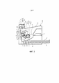
[0011] Фиг. 3 является схематичным видом сбоку в сечении состояния, в котором картридж с тонером устанавливается на проявочном узле.[0011] FIG. 3 is a schematic cross-sectional side view of a state in which a toner cartridge is mounted on a developing unit.
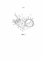
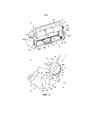
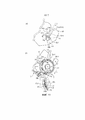
[0012] Фиг. 4 является схематичным видом в перспективе проявочного узла согласно варианту осуществления.[0012] FIG. 4 is a schematic perspective view of a developing unit according to an embodiment.
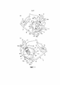
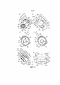
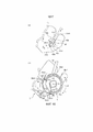
[0013] Фиг. 5 является схематичным видом картриджа с тонером согласно варианту осуществления.[0013] FIG. 5 is a schematic view of a toner cartridge according to an embodiment.
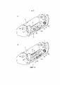
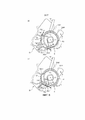
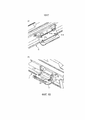
[0014] Фиг. 6 является схематичной иллюстрацией проявочного узла и картриджа с тонером перед установкой (вставкой).[0014] FIG. 6 is a schematic illustration of a developing unit and toner cartridge prior to installation (insertion).
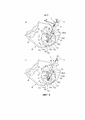
[0015] Фиг. 7 является схематичной иллюстрацией проявочного узла и картриджа с тонером в ходе установки (вставки).[0015] FIG. 7 is a schematic illustration of a developing unit and toner cartridge during installation (insertion).
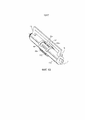
[0016] Фиг. 8 является видом сбоку в сечении, иллюстрирующим модифицированный пример конструкции удлиняющегося участка и примыкающего участка картриджа с тонером.[0016] FIG. 8 is a side cross-sectional view illustrating a modified example of the structure of the extension portion and the abutting portion of the toner cartridge.
[0017] Фиг. 9 является схематичным видом сбоку, иллюстрирующим взаимосвязь сил, действующих на картридж с тонером.[0017] FIG. 9 is a schematic side view illustrating the relationship of forces acting on a toner cartridge.
[0018] Фиг. 10 является схематичной иллюстрацией, показывающей состояние, в котором примыкающий участок примыкает к примыкаемому участку.[0018] FIG. 10 is a schematic illustration showing a state in which an abutting portion is adjacent to an abutting portion.
[0019] Фиг. 11 является схематичной иллюстрацией, когда рама контейнера вращается, и картридж с тонером позиционируется.[0019] FIG. 11 is a schematic illustration when the container frame rotates and the toner cartridge is positioned.
[0020] Фиг. 12 является схематичной иллюстрацией, когда каждый затвор перемещается в открытую позицию, и каждый участок для хранения тонера сообщается.[0020] FIG. 12 is a schematic illustration when each shutter is moved to the open position and each toner storage portion is communicated.
[0021] Фиг. 13 является видом в перспективе, иллюстрирующим модифицированный пример конструкции примыкающего участка картриджа с тонером.[0021] FIG. 13 is a perspective view illustrating a modified construction example of an abutting portion of a toner cartridge.
[0022] Фиг. 14 является видом сбоку конструкции, в которой картридж с тонером содержит участок для передачи приводного усилия, зацепленный со вторым участком для передачи приводного усилия.[0022] FIG. 14 is a side view of a structure in which the toner cartridge includes a driving force transmitting portion engaged with a second driving force transmitting portion.
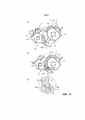
[0023] Фиг. 15 является видом, иллюстрирующим модифицированный пример проявочного узла.[0023] FIG. 15 is a view illustrating a modified example of a developing unit.
[0024] Фиг. 16 является видом, иллюстрирующим модифицированный пример проявочного узла.[0024] FIG. 16 is a view illustrating a modified example of a developing unit.
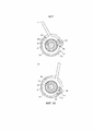
[0025] Фиг. 17 является иллюстрацией взаимосвязи компоновки вторых затворов.[0025] FIG. 17 is an illustration of the relationship of the arrangement of the second closures.
Описание вариантов осуществленияDescription of embodiments
[0026] В дальнейшем описываются устройство формирования изображений для формирования электрофотографического изображения, участок для формирования тонерных изображений и картридж с тонером в сочетании с прилагаемыми чертежами. Здесь, устройство формирования изображений формирует изображение на записывающем материале посредством использования, например, процесса формирования электрофотографических изображений. Например, оно включает в себя электрофотографический копировальный аппарат, электрофотографический принтер (например, светодиодный принтер, лазерный принтер и т.д.), электрофотографический факсимильный аппарат и т.д.[0026] In the following, an image forming apparatus for forming an electrophotographic image, a portion for forming toner images, and a toner cartridge will be described in conjunction with the accompanying drawings. Here, the imaging apparatus forms an image on the recording material by using, for example, an electrophotographic imaging process. For example, it includes an electrophotographic copier, an electrophotographic printer (such as an LED printer, a laser printer, etc.), an electrophotographic facsimile machine, etc.
[0027] Здесь, в нижеприведенных вариантах осуществления, примерно иллюстрируется устройство формирования монохромных изображений, содержащее один участок для формирования тонерных изображений. Тем не менее, число участков для формирования тонерных изображений, предоставленных в устройстве формирования изображений, не ограничено одним. Например, устройство формирования изображений может включать в себя множество участков для формирования тонерных изображений, чтобы формировать цветное изображение.[0027] Here, in the following embodiments, a monochrome imaging apparatus comprising one toner imaging portion is exemplarily illustrated. However, the number of toner image forming portions provided in the imaging apparatus is not limited to one. For example, the imaging apparatus may include a plurality of toner imaging portions to form a color image.
[0028] Аналогично, в каждой конструкции, раскрытой в варианте осуществления, материалы, компоновки, размеры, другие числовые значения и т.д. не ограничены примерами раскрытия сущности, если нет конкретных ограничений. Помимо этого, если не указано иное, "выше" означает вверх в направлении силы тяжести, когда устройство формирования изображений устанавливается.[0028] Similarly, in each structure disclosed in the embodiment, materials, arrangements, dimensions, other numerical values, and so on. are not limited to the disclosure examples unless there are specific restrictions. In addition, unless otherwise indicated, "above" means upward in the direction of gravity when the imaging apparatus is installed.
Вариант 1 осуществления
[0029] В этом варианте осуществления, подробно описывается конструкция, которая способствует повышению удобства и простоты использования. Более конкретно, это вариант осуществления относится к улучшению ощущений при выполнении действий, когда пользователь устанавливает картридж с тонером в проявочный узел.[0029] In this embodiment, a structure that enhances convenience and ease of use is described in detail. More specifically, this embodiment relates to improving the operating feel when the user installs the toner cartridge into the developing unit.
[0030] Во-первых, описывается конструкция устройства формирования полного изображения, и далее подробно описываются проявочный узел и картридж с тонером. Здесь, операция установки картриджа с тонером в проявочный узел упоминается как операция установки, и операция извлечения картриджа с тонером из проявочного узла называется операцией снятия.[0030] First, the structure of the complete image forming apparatus is described, and the following describes the developing unit and the toner cartridge in detail. Here, the operation of mounting the toner cartridge to the developing unit is referred to as a mounting operation, and the operation of removing the toner cartridge from the developing unit is referred to as a peeling operation.
[0031] Помимо этого, позиция, в который выступ, полость и т.д. зацепляются друг с другом, упоминается как позиция зацепления, и позиция, в которой зацепление прекращается, упоминается как позиция отсутствия зацепления (позиция расцепления).[0031] In addition, the position at which the projection, cavity, etc. engaging with each other is referred to as an engaging position, and the position at which the engagement stops is referred to as a non-engaging position (disengaging position).
Устройство формирования электрофотографических изображенийElectrophotographic Imaging Device
[0032] Фиг. 2 является видом в сечении сбоку, иллюстрирующим конструкцию устройства A формирования изображений согласно этому варианту осуществления. Устройство A формирования изображений, показанное на фиг. 2, принимает информацию изображений из внешнего устройства, такого как персональный компьютер, который соединяется с возможностью связи с ним. Так же, в соответствии с принимаемой информацией изображений, устройство A формирования изображений формирует изображение (тонерное изображение) посредством проявителя (тонера) на записывающем материале P (например, на записывающем листе, OHP-листе, ткани и т.д.) посредством процесса формирования электрофотографических изображений.[0032] FIG. 2 is a side sectional view illustrating the structure of the image forming apparatus A according to this embodiment. The imaging apparatus A shown in FIG. 2 receives image information from an external device, such as a personal computer, which is communicatively connected therewith. Also, according to the received image information, the imaging apparatus A forms an image (toner image) by means of a developer (toner) on a recording material P (e.g., a recording sheet, OHP sheet, fabric, etc.) through a formation process electrophotographic images.
[0033] В устройстве A формирования изображений, участок B для формирования тонерных изображений (узел формирования тонерных изображений) может устанавливаться в главный сборочный узел. Участок B для формирования тонерных изображений (узел формирования тонерных изображений) этого варианта осуществления включает в себя узел C барабана, проявочный узел D (проявочное устройство) и картридж E с тонером. Картридж E с тонером может устанавливаться и извлекаться из проявочного узла D. Таким образом, проявочный узел D включает в себя установочный участок для установки картриджа E с тонером и представляет собой приемное устройство (приемное устройство) для приема картриджа E с тонером.[0033] In the imaging apparatus A, a toner image forming portion B (a toner imaging unit) may be installed in the main assembly. The toner image forming portion B (toner imaging unit) of this embodiment includes a drum unit C, a developing unit D (developing unit), and a toner cartridge E. The toner cartridge E can be installed and removed from the developing unit D. Thus, the developing unit D includes a mounting portion for mounting the toner cartridge E and is a receiver (receiver) for receiving the toner cartridge E.
[0034] Здесь, участок B для формирования тонерных изображений (узел формирования тонерных изображений) может рассматриваться в качестве узла, включающего в себя фоточувствительный барабан и элементы, действующие на фоточувствительный барабан.[0034] Here, the toner image forming portion B (toner image forming unit) can be regarded as an assembly including a photosensitive drum and members acting on the photosensitive drum.
[0035] Узел C барабана и проявочный узел D интегрируются в один картридж, который может устанавливаться с возможностью снятия в главный сборочный узел устройства формирования изображений. Картридж, в котором интегрируются узел C барабана и проявочный узел D, иногда, в частности, называется технологическим картриджем. Таким образом, картридж E с тонером устанавливается и извлекается из проявочного узла D технологического картриджа. В этом случае, весь технологический картридж также может рассматриваться в качестве приемного устройства.[0035] The drum unit C and the developing unit D are integrated into a single cartridge, which can be detachably installed in the main assembly of the image forming apparatus. The cartridge in which the drum unit C and the developing unit D are integrated is sometimes specifically referred to as a process cartridge. Thus, the toner cartridge E is installed and removed from the developing unit D of the process cartridge. In this case, the entire process cartridge can also be considered as a receiving device.
[0036] Помимо этого, когда картридж E с тонером установлен на проявочном узле D, технологический картридж может устанавливаться и извлекаться из главного сборочного узла устройства. Таким образом, узел C барабана, проявочный узел D и картридж E с тонером могут устанавливаться и извлекаться из главного сборочного узла устройства в интегрированном состоянии. Следовательно, узел B формирования тонерных изображений (узел формирования тонерных изображений), включающий в себя все из узла C барабана, проявочного узла D и картриджа E с тонером, может упоминаться как технологический картридж.[0036] In addition, when the toner cartridge E is installed on the developing unit D, the process cartridge can be installed and removed from the main assembly of the apparatus. Thus, the drum unit C, the developing unit D, and the toner cartridge E can be installed and removed from the main assembly of the apparatus in an integrated state. Therefore, the toner imaging unit B (toner imaging unit) including all of the drum unit C, the developing unit D, and the toner cartridge E may be referred to as a process cartridge.
[0037] Здесь, узел C барабана, проявочный узел D и картридж E с тонером могут на ранней стадии формироваться в картриджи в некоторых случаях. В этом случае, узел C барабана может упоминаться как барабан-картридж, и проявочный узел D может упоминаться как проявочный картридж. Помимо этого, в некоторых случаях, фоточувствительный барабан (или узел барабана, включающий в себя фоточувствительный барабан) прикрепляется к главному сборочному узлу устройства, и только проявочный узел D (проявочный картридж) и картридж E с тонером могут устанавливаться и извлекаться.[0037] Here, the drum unit C, the developing unit D, and the toner cartridge E may be formed into cartridges at an early stage in some cases. In this case, the drum unit C may be referred to as a drum cartridge, and the developing unit D may be referred to as a developing cartridge. In addition, in some cases, the photosensitive drum (or the drum unit including the photosensitive drum) is attached to the main assembly of the apparatus, and only the developing unit D (developing cartridge) and the toner cartridge E can be installed and removed.
[0038] Помимо этого, фоточувствительный барабан и/или проявочный узел могут прикрепляться к главному сборочному узлу устройства, и только картридж E с тонером может устанавливаться с возможностью снятия в главный сборочный узел устройства. В этом случае, само устройство формирования изображений может рассматриваться в качестве приемного устройства для картриджа E с тонером.[0038] In addition, the photosensitive drum and / or the developing unit can be attached to the main assembly of the apparatus, and only the toner cartridge E can be detachably mounted to the main assembly of the apparatus. In this case, the image forming apparatus itself can be regarded as a receiving apparatus for the toner cartridge E.
[0039] Помимо этого, компоненты, включающие в себя приемное устройство (проявочный узел D) и картридж E с тонером, могут упоминаться как механизм подачи тонера (узел подачи тонера, устройство подачи тонера) и т.п. В механизме подачи тонера, тонер подается (пополняется) из картриджа E с тонером в приемное устройство.[0039] In addition, components including a receiving device (developing unit D) and a toner cartridge E may be referred to as a toner supply mechanism (toner supply unit, toner supply unit) and the like. In the toner supply mechanism, toner is fed (replenished) from the toner cartridge E to the receptacle.
[0040] Здесь, в этом примере, фоточувствительный барабан в качестве несущего изображение элемента имеет конструкцию, в которой фланец и т.п. устанавливается как единое целое в цилиндр, включающий в себя фоточувствительный слой.[0040] Here, in this example, the photosensitive drum as an image bearing member has a structure in which a flange or the like is is installed as a single unit in a cylinder that includes a photosensitive layer.
[0041] Установка и снятие каждого картриджа выполняется пользователем (оператором, пользователем). Помимо этого, главный сборочный узел устройства (главный сборочный узел устройства формирования изображений) означает участок конструкции с исключением каждого картриджа (узла C барабана, проявочного узла D и картриджа E с тонером) из устройства A формирования изображений.[0041] The installation and removal of each cartridge is performed by the user (operator, user). In addition, the apparatus main assembly (imaging apparatus main assembly) means a structure portion excluding each cartridge (drum unit C, developing unit D, and toner cartridge E) from the imaging apparatus A.
[0042] Узел C барабана представляет собой узел, в котором фоточувствительный барабан 16 (несущий изображение элемент), зарядный валик 17, ракель 19 и т.п. объединяются как единое целое, и в этом варианте осуществления, он представляет собой картридж (барабан-картридж), устанавливаемый и извлекаемый из главного сборочного узла устройства. Помимо этого, проявочный узел D представляет собой узел, в котором проявочный валик 24 (элемент переноса проявителя) и т.п. интегрируются в качестве узла, и в этом варианте осуществления, он представляет собой участок картриджа, устанавливаемый и извлекаемый из главного сборочного узла устройства. Картридж E с тонером представляет собой картридж, в котором контейнер 47 с тонером (контейнер с проявителем, контейнер) и т.п. для содержания тонера t в качестве проявителя формируются как единое целое в качестве картриджа.[0042] The drum unit C is a unit in which a photosensitive drum 16 (image bearing member), a
[0043] Фоточувствительный барабан 16 вращается в направлении стрелки a, показанной на фиг. 2. Поверхность вращающегося фоточувствительного барабана 16 равномерно заряжается посредством зарядного валика 17 в качестве средства заряда. Лазерный луч L, соответствующий информации изображений, облучается из лазерного сканера 1 (средства экспозиции) на фоточувствительный барабан 16 таким образом, что электростатическое скрытое изображение, соответствующее информации изображений, формируется на фоточувствительном барабане 16. Так же, тонер t, переносимый на проявочном валике 24, проявляет электростатическое скрытое изображение. В силу этого, тонерное изображение формируется на фоточувствительном барабане 16.[0043] The
[0044] Здесь, ссылаясь на фиг. 3, в дальнейшем поясняется процесс проявки во участке B для формирования тонерных изображений. Рама 35 проявочного узла D в качестве приемного устройства поддерживает с возможностью вращения проявочный валик 24. Проявочный валик 24 принимает движущую силу из источника мощности, такого как электромотор (не показан), обеспеченного в главном сборочном узле устройства, и вращательно приводится в действие в прямом направлении (в направлении стрелки b на чертеже) относительно фоточувствительного барабана 16.[0044] Here, referring to FIG. 3, the developing process in the toner image forming portion B will be explained below. The developing
[0045] Тонер t в проявочной камере 31 переносится на периферийную поверхность проявочного валика 24 с толщиной слоя, регулируемой посредством проявочного лезвия 25. Когда толщина слоя регулируется, электрический заряд прикладывается к тонеру посредством трибоэлектрического заряда. Так же, заряженный тонер проявляет электростатическое скрытое изображение на фоточувствительном барабане 16.[0045] The toner t in the developing
[0046] В проявочном узле D, проявочная камера 31 сообщается с первым участком 28 для содержания тонера (участком размещения проявителя) через участок 29 первого отверстия. Первое средство 27 подачи тонера, которое вращательно приводится в действие посредством источника приведения в действие (не показан), подает тонер t из первого участка для содержания тонера 28 в проявочную камеру 31.[0046] In the developing unit D, the developing
[0047] Помимо этого, сообщающийся участок 58 формируется посредством участка 30 второго отверстия (отверстия в корпусе для содержания, приемного порта, приемного отверстия) и участка 49 третьего отверстия (отверстия в контейнере, выпускного порта, выпускного отверстия). Через этот сообщающийся участок 58, первый участок 28 для содержания тонера (размещающая камера для элемента для содержания) сообщается со вторым участком 47t для содержания тонера (размещающей камерой в контейнере) картриджа E с тонером.[0047] In addition, the communicating
[0048] Второй контейнер 47t с тонером содержит тонер, и в силу этого он представляет собой пространство, предоставленное в контейнере 47. Второй участок 47t для хранения тонера представляет собой участок для хранения (участок для хранения тонера, участок для хранения проявителя), сформированный посредством рамы (рамы 47a контейнера) контейнера 47.[0048] The second toner container 47t contains toner, and therefore is a space provided in the
[0049] Участок 49 третьего отверстия формируется в раме 47a контейнера и представляет собой выпускное отверстие для выпуска тонера из второго участка 47t для содержания тонера за пределы контейнера 47 с тонером (т.е. проявочного узла D). Тонер, выпускаемый из участка 49 третьего отверстия, принимается во втором отверстии 30 (приемном порту) проявочного узла D.[0049] The
[0050] В первый участок 28 для содержания тонера, тонер t подается из второго участка 47t для содержания тонера посредством второго элемента 46 подачи тонера, который вращается посредством движущей силы, введенной из главного сборочного узла устройства посредством проявочного узла D.[0050] To the first toner-containing
[0051] Возвращаясь к фиг. 2, приводится более подробное описание. Записывающий материал P, заданный в подающей кассете 2, разделяется и подается поочередно посредством собирающего валика 3 и прижимного контактного элемента 5, прижимаемого к собирающему валику 3. Так же, синхронно с тонерным изображением, сформированным на фоточувствительном барабане, записывающий материал P подается вдоль подающей направляющей 4 в валик 6 переноса в качестве средства переноса.[0051] Referring back to FIG. 2 is described in more detail. The recording material P specified in the feeding
[0052] Затем, записывающий материал P проходит через захватный участок 11 переноса, сформированный посредством фоточувствительного барабана 16, и применяется валик 6 переноса, в который подается неизменяющееся постоянное напряжение. В это время, тонерное изображение, сформированное на фоточувствительном барабане 16, переносится на записывающий материал P. Записывающий материал P, на который переносится тонерное изображение, подается в закрепляющее средство 8 вдоль подающей направляющей 7.[0052] Then, the recording material P passes through the transfer nip 11 formed by the
[0053] Закрепляющее средство 8 включает в себя приводной валик 8a и закрепляющий валик 8c, включающий нагреватель 8b. Записывающий материал P подвергается термосиловому закреплению при прохождении через захватный участок 8d сформированный между закрепляющим валиком 8c и приводным валиком 8a. В силу этого, тонерное изображение, переносимое на записывающий материал P, закрепляется на записывающем материале P. После этого, записывающий материал P, на котором закреплено тонерное изображение, подается посредством пары выпускных валиков 9 и выпускается в выпускной лоток 10.[0053] The securing means 8 includes a
[0054] Ракель 19 входит в эластичный контакт с внешней периферийной поверхностью фоточувствительного барабана 16. В силу этого, тонер t (неперенесенный остаточный тонер), остающийся на фоточувствительном барабане 16, который не перенесен на записывающий материал P, счищается посредством ракеля 19. Счищенный тонер t хранится во участке 18a для содержания извлеченного тонера (участке для содержания отработанного тонера) рамы 18, к которой прикрепляется ракель 19.[0054] The
[0055] Как описано выше, в устройстве формирования изображений этого варианта осуществления, изображение формируется на записывающем материале (записывающем материале) с помощью проявителя (тонера) через способ формирования электрофотографических изображений. Естественно, удовлетворительно формировать изображение на записывающем материале в качестве устройства формирования изображений, и в силу этого электрофотографический копировальный аппарат, электрофотографический принтер (лазерный принтер, светодиодный принтер и т.д.), электрофотографический факсимильный аппарат, электрофотографический текстовый процессор и т.п. являются применимыми, и их форма не ограничена.[0055] As described above, in the imaging apparatus of this embodiment, an image is formed on a recording material (recording material) with a developer (toner) through an electrophotographic imaging method. Naturally, it is satisfactory to form an image on a recording material as an imaging apparatus, and therefore an electrophotographic copier, an electrophotographic printer (laser printer, LED printer, etc.), an electrophotographic facsimile machine, an electrophotographic word processor, and the like. are applicable and their form is not limited.
[0056] Как описано выше, участок B для формирования тонерных изображений включает в себя электрофотографический фоточувствительный элемент (фоточувствительный элемент), который представляет собой несущий изображение элемент, и технологическое средство, действующее на фоточувствительный элемент. В этом варианте осуществления, участок для формирования тонерных изображений может устанавливаться с возможностью снятия в главный сборочный узел устройства формирования изображений в качестве одного или более картриджей.[0056] As described above, the toner image forming portion B includes an electrophotographic photosensitive member (photosensitive member), which is an image carrying member, and processing means acting on the photosensitive member. In this embodiment, the toner imaging portion may be removably mounted to the main assembly of the imaging apparatus as one or more cartridges.
[0057] Технологическое средство включает в себя средство заряда (зарядный элемент, зарядное устройство), средство проявки (проявочное устройство, проявочный узел), средство очистки (устройство очистки, элемент очистки) и т.п.[0057] The processing means includes charging means (charging cell, charger), developing means (developing device, developing unit), cleaning means (cleaning device, cleaning element) and the like.
[0058] Проявочное устройство представляет собой устройство, используемое для проявки электростатического скрытого изображения, сформированного на фоточувствительном элементе. В этом варианте осуществления, проявочное устройство (проявочный узел) формируется в картридж и может извлекаться из устройства формирования изображений в качестве узла. С другой стороны, проявочное устройство может составлять участок технологического картриджа.[0058] The developing device is a device used for developing an electrostatic latent image formed on a photosensitive member. In this embodiment, the developing device (developing unit) is formed into a cartridge and can be removed from the image forming apparatus as an assembly. Alternatively, the developing device may constitute a portion of the process cartridge.
[0059] Помимо этого, картридж с тонером (проявочный картридж, емкость с тонером, емкость с проявителем, контейнер с тонером, контейнер с проявителем) представляет собой картридж, содержащий проявитель (тонер), используемый для проявки электростатического скрытого изображения, сформированного на фоточувствительном элементе.[0059] In addition, a toner cartridge (developing cartridge, toner container, developer container, toner container, developer container) is a cartridge containing a developer (toner) used to develop an electrostatic latent image formed on a photosensitive member ...
Конструкция каждого картриджа (каждого узла)Design of each cartridge (each unit)
[0060] В дальнейшем описывается подробная конструкция каждого картриджа (каждого узла), обеспеченного с возможностью снятия в устройстве формирования изображений.[0060] Hereinafter, a detailed structure of each cartridge (each assembly) removable in an image forming apparatus will be described.
Подробности окружения участка для приема картриджей с тонером проявочного узлаDetails of the surroundings of the toner cartridge receiving area of the developing unit
[0061] Ссылаясь на фиг. 4, в дальнейшем описывается подробная конструкция окружения приемного участка картриджа E с тонером проявочного узла D согласно этому варианту осуществления. Фиг. 4 является видом в перспективе окружения приемного участка (установочного участка) картриджа E с тонером проявочного узла D. Часть (a) по фиг. 4 показывает состояние, в котором участок 30 второго отверстия является закрытым (первый затвор 37 находится в закрытой позиции). Помимо этого, часть (b) по фиг. 4 иллюстрирует состояние, в котором участок 30 второго отверстия является открытым (первый затвор 37 находится в открытой позиции). В этом примере, продольное направление проявочного узла D представляет собой направление, параллельное с направлением оси вращения проявочного валика 24 проявочного узла D. Здесь, в состоянии, в котором картридж E с тонером устанавливается в проявочный узел, продольное направление картриджа E с тонером является по существу параллельным с продольным направлением проявочного узла D[0061] Referring to FIG. 4, the following describes a detailed structure of surrounding the receiving portion of the toner cartridge E of the developing unit D according to this embodiment. FIG. 4 is a perspective view of the surrounding of the receiving portion (mounting portion) of the toner cartridge E of the developing unit D. Part (a) of FIG. 4 shows the state in which the
[0062] В проявочном узле D, картридж E с тонером может устанавливаться (или извлекаться) в раму 35 (проявочную раму). В окружении приемного участка, проявочный узел D имеет второе отверстие 30 (отверстие в корпусе для содержания, приемный порт) и первый затвор 37 (затвор корпуса для содержания, затвор на стороне приемного устройства, элемент открытия/закрытия на стороне приемного устройства). В этом варианте осуществления, участок 30 второго отверстия обеспечен в центральном участке в продольном направлении проявочного узла D. Тем не менее, позиция участка 30 второго отверстия не ограничена центральным участком в продольном направлении при условии, что он обращен к третьему отверстию 49 (отверстию в контейнере), которое описывается в дальнейшем.[0062] In the developing unit D, the toner cartridge E may be installed (or removed) in the frame 35 (developing frame). Surrounded by the receiving area, the developing unit D has a second opening 30 (housing opening, receiving port) and a first shutter 37 (housing housing gate, receiving device side gate, receiving device side opening / closing member). In this embodiment, the
[0063] Как показано в части (a) по фиг. 4, участок 30 второго отверстия уплотняется посредством первого затвора 37, включающего в себя форму, имеющую кривизну вдоль внешней периферийной поверхности картриджа E с тонером.[0063] As shown in part (a) of FIG. 4, the
[0064] Первый затвор 37 имеет полый участок 37a, который зацепляется с выступом 45 (зацепляющим участком на стороне контейнера, перемещающим участком элемента открытия/закрытия, выступом на стороне контейнера), предоставленным в картридже E с тонером в качестве контейнера с проявителем. Предусмотрено два таких выступа 45 и два таких полых участка 37. Этот полый участок 37a обеспечен за пределами уплотненной зоны, в которой первый затвор 37 уплотняет участок 30 второго отверстия.[0064] The
[0065] Помимо этого, концевые участки, в продольном направлении, первого затвора 37 зацепляются с направляющими участками 34 первого затвора, предоставленными на соответствующих сторонах, в продольном направлении, участка 30 второго отверстия в раме 35 проявочного узла D. В силу этого, первый затвор сконструирован таким образом, что он является скользящим (перемещаемым) вдоль направляющего участка 34 первого затвора (направлений стрелок W1 и W2).[0065] In addition, the end portions, in the longitudinal direction, of the
[0066] За счет этого, первый затвор 37 выполнен с возможностью перемещения между закрытой позицией для закрытия участка 30 второго отверстия (закрытой позицией приемного отверстия, часть (a) по фиг. 4) и открытой позицией (открытой позицией приемного порта, часть (b) по фиг. 4) для открытия участка 30 второго отверстия.[0066] Due to this, the
[0067] Помимо этого, проявочный узел D содержит участок 35x для приема тонера (участок приложения силы закрытия) и участок 35y для приема тонера ниже направления g силы тяжести участка 30 второго отверстия (часть (b) по фиг. 4), чтобы не позволять тонеру t, утекающему через участок 30 второго отверстия, выпадать из проявочного узла D. Участок 35y для приема тонера представляет собой поверхность, покрытую первым затвором 37, занимающим открытую позицию (часть (a) по фиг. 4). Участок 35x для приема тонера представляет собой выступ, предоставленный в концевом участке участка 35y для приема тонера, и продолжается в продольном направлении.[0067] In addition, the developing unit D includes a
В этом примере, компоновка участков 35x и 35y для приема тонера в продольном направлении является такой, что они являются наружными относительно участка 30 второго отверстия в продольном направлении и наружными относительно полого участка 37a в продольном направлении (не показано). Тем не менее, компоновка участков 35x и 35y для приема тонера в продольном направлении не ограничена этим примером. Тем не менее, с такой точки зрения, чтобы не позволять тонеру t, утекающему через участок 30 второго отверстия, выпадать из картриджа, предпочтительно, если он проходит в область за пределами участка 30 второго отверстия относительно продольного направления.In this example, the arrangement of the
[0068] Даже если тонер утекает из участка 30 второго отверстия, когда первый затвор 37 перемещается, тонер может поддерживаться на участке 35y для приема тонера и участке 35x для приема тонера. Это подавляет вхождение тонера в главный сборочный узел устройства из картриджа.[0068] Even if toner leaks out of the
[0069] Помимо этого, как показано в части (b) по фиг. 4, первое герметизирующее уплотнение 32 для уплотнения зазора между первым затвором 37 и участком 30 второго отверстия устанавливается в раму 35 проявочного узла D таким образом, что оно окружает участок 30 второго отверстия.[0069] In addition, as shown in part (b) of FIG. 4, a
[0070] Проявочный узел D обеспечен на противоположных продольных концах с направляющими участками 35d, 36d для вставки (направляющими на стороне приемного устройства) для направления картриджа E с тонером при поддержании ориентации в пространстве (ориентации в пространстве при установке) картриджа с тонером при установке (вставке) картриджа E с тонером в раму 35.[0070] A developing unit D is provided at opposite longitudinal ends with
[0071] Помимо этого, проявочный узел D содержит примыкаемые участки 35a, 36a, к которым примыкают примыкающие участки 42a, 43a картриджа E с тонером, когда картридж E с тонером вставляется, как описано ниже.[0071] In addition, the developing unit D includes abutting
[0072] Кроме того, проявочный узел D имеет направляющие участки 35b, 36b для обеспечения вращения для направления вращения картриджа E с тонером на противоположных продольных концах рамы 35 при открытии и закрытии первого затвора 37 и второго затвора 53 (затвора контейнера).[0072] In addition, the developing unit D has
[0073] Направляющие участки 35d, 36d для вставки линейно протягиваются параллельно друг другу вдоль направления f вставки (часть (a) по фиг. 4) картриджа E с тонером. Здесь, направление, противоположное направлению вставки картриджа E с тонером, иногда упоминается в качестве направления извлечения (направления для извлечения картриджа E с тонером из проявочного узла D) в некоторых случаях. В этом случае, сторона ниже по ходу в направлении вставки может рассматриваться в качестве стороны выше по ходу в направлении извлечения, и сторона выше по ходу вставки может рассматриваться в качестве стороны ниже по ходу в направлении извлечения.[0073] The
[0074] В проявочном узле D, примыкаемый участок 35a и направляющий участок 35b для обеспечения вращения предоставляются на стороне ниже по ходу, в направлении f вставки, направляющего участка 35d для вставки на неприводящей стороне в приводящей стороне, и примыкаемый участок 36a и направляющая 36b для обеспечения вращения предоставляются на стороне ниже по ходу, в направлении f вставки, направляющего участка 36d для вставки.[0074] In the developing unit D, the abutting
[0075] Здесь, относительно противоположных концевых сторон в продольном направлении проявочного участка D, сторона, на которой располагается приводящий участок, такой как шестерня (например, первый участок 38 для передачи приводного усилия), в дальнейшем называется приводящей стороной. Неприводящая сторона проявочного узла является противоположной относительно приводящей стороны в продольном направлении.[0075] Here, with respect to opposite end sides in the longitudinal direction of the developing portion D, the side on which the driving portion such as a gear is located (eg, the first driving force transmission portion 38) is hereinafter referred to as the driving side. The non-driving side of the developing unit is opposite to the driving side in the longitudinal direction.
[0076] Кроме того, первый участок 38 для передачи приводного усилия для передачи приводного усилия во второе средство 46 подачи тонера картриджа E с тонером, который описывается в дальнейшем, обеспечен на одном конце, в продольном направлении, рамы 35 проявочного узла D.[0076] In addition, the first driving
[0077] Первый участок 38 для передачи приводного усилия представляет собой шестерню и соединяется с приводным механизмом главного сборочного узла устройства формирования изображений в проявочном узле D. Первый участок 38 для передачи приводного усилия представляет собой участок для передачи крутящего момента (участок для передачи движущей силы) для передачи вращающей силы для приведения в действие второго элемента 46 подачи тонера из-за пределов картриджа E с тонером.[0077] The first driving
Подробное описание картриджа с тонеромDetailed description of the toner cartridge
[0078] Ссылаясь на фиг. 5, в дальнейшем описывается подробная конструкция картриджа E с тонером согласно этому варианту осуществления.[0078] Referring to FIG. 5, the following describes the detailed structure of the toner cartridge E according to this embodiment.
[0079] Часть (a) по фиг. 5 является видом в перспективе картриджа E с тонером, если смотреть со стороны второй части 48 для передачи приведения в действие (приводящей стороны). Помимо этого, часть (b) по фиг. 5 является видом в перспективе в состоянии, в котором второй затвор 53 закрывает участок 49 третьего отверстия, если смотреть на картридж E с тонером со стороны, противоположной стороне второго участка 48 для передачи приводного усилия (неприводящей стороне). Часть (c) по фиг. 5 является видом в сечении картриджа E с тонером в закрытом состоянии участка 49 третьего отверстия, если смотреть со стороны, противоположной стороне второго участка 48 для передачи приводного усилия. Помимо этого, часть (d) по фиг. 5 является видом в сечении картриджа E с тонером в состоянии, в котором участок 49 третьего отверстия открыт, если смотреть со стороны, противоположной стороне второго участка 48 для передачи приводного усилия. Так же, часть (e) по фиг. 5 является видом в перспективе второго затвора 53 картриджа E с тонером, когда он находится в открытой позиции (в состоянии, в котором участок 49 третьего отверстия является открытым). Часть (f) по фиг. 5 является укрупненным видом окружения третьего отверстия с участком 49 третьего отверстия в открытом состоянии. Здесь, на фиг. 5, тонер t не показан.[0079] Part (a) of FIG. 5 is a perspective view of the toner cartridge E when viewed from the side of the second driving transmission portion 48 (driving side). In addition, part (b) of FIG. 5 is a perspective view in a state in which the
[0080] Картридж E с тонером содержит контейнер 47, второй затвор 53 (затвор контейнера с проявителем), перемещаемый относительно контейнера 47, второй элемент 46 подачи тонера, предоставленный внутри контейнера 47, и второй участок 48 для передачи приводного усилия (шестерню), установленный во втором элементе 46 подачи тонера.[0080] Toner cartridge E comprises a
[0081] Контейнер 47 имеет по существу цилиндрическую форму. Таким образом, рама 47a (рама контейнера), составляющая участок корпуса (основной участок) контейнера 47, имеет по существу цилиндрическую форму. Здесь, продольное направление картриджа E с тонером представляет собой продольное направление цилиндрической формы.[0081] The
[0082] Направляемый участок 42 для вставки (направляемый участок, направляющий участок на стороне картриджа с тонером), выступающий наружу, в продольном направлении, боковой стенки 47a2 рамы 47a контейнера, обеспечен в концевом участке в продольном направлении, контейнера 47. Аналогично, в другом продольном концевом участке контейнера 47, обеспечен направляемый участок 43 для вставки (направляемый участок, направляющий участок на стороне картриджа с тонером), выступающий наружу, в продольном направлении, боковой стенки 47a1 рамы 47a контейнера.[0082] An insertion guided portion 42 (a guided portion, a guiding portion on the toner cartridge side) protruding outward in the longitudinal direction of the side wall 47a2 of the
[0083] Помимо этого, контейнер 47 имеет функциональный участок 44, который должен управляться пользователем. Функциональный участок 44 представляет собой U-образный выступ, сформированный как единое целое с рамой 47a. Здесь, форма функционального участка 44 не ограничена U-образной формой. Помимо этого, функциональный участок 44 может формироваться как единое целое с рамой 47a контейнера или может быть изготовлен из элемента, отличающегося от рамы 47a и установленного в раму 47a. Функциональный участок 44 представляет собой удерживающий участок (захват, захватную секцию) для захвата пользователем, при вставке или извлечении картриджа E с тонером.[0083] In addition, the
[0084] Как показано в части (c) по фиг. 5, рама контейнера (цилиндрический участок) 47a является полой и формирует второй участок 47t для содержания тонера, в котором размещается тонер t. Второй элемент 46 подачи тонера для подачи тонера обеспечен с возможностью вращения во втором участке 47t для содержания тонера рамы 47a контейнера. Второй участок 48 для передачи приводного усилия для приема мощности (вращающей силы, движущей силы) для вращательного приведения в действие второго элемента 46 подачи тонера, обеспечен в одном концевом участке, в продольном направлении (направлении оси вращения), второго элемента 46 подачи тонера (часть (a) по фиг. 5). Второй участок 48 для передачи приводного усилия представляет собой шестерню (ведущую входную шестерню), которая принимает движущую силу (вращающую силу) из-за пределов (т.е. из проявочного узла D в качестве приемного устройства) картриджа E с тонером.[0084] As shown in part (c) of FIG. 5, the container frame (cylindrical portion) 47a is hollow and forms a second toner-containing portion 47t in which the toner t is received. The second
[0085] Здесь, в этом варианте осуществления, движущая сила непосредственно передается от второго участка 48 для передачи приводного усилия, который представляет собой ведущую входную шестерню, во второй элемент 46 подачи тонера. Тем не менее, движущая сила может передаваться от ведущей входной шестерни во второй элемент 46 подачи тонера через другой элемент передачи приводного усилия (например, одну или множество шестерней). Ссылаясь на фиг. 14, в дальнейшем описывается такая конструкция, как указано.[0085] Here, in this embodiment, the driving force is directly transmitted from the second driving
[0086] Рама 47a контейнера содержит два выступа 45, предоставленные таким образом, что они являются зацепляемыми с полым участком 37a первого затвора 37 на внешнем периметре его цилиндрической формы. Два выступа 45 выступают по существу в идентичном направлении. В направлении вставки картриджа E с тонером в проявочный узел D, выступ 45 выступает к стороне ниже по ходу.[0086] The
[0087] Помимо этого, линия, соединяющая два выступа 45, является по существу параллельной продольному направлению картриджа E с тонером. Как показано в части (f) по фиг. 5, в продольном направлении контейнера 47, два выступа 45 размещаются за пределами участка 49 третьего отверстия. Более подробно, когда два выступа 45 и участок 49 третьего отверстия проецируются на воображаемую линию, параллельную центральной оси R рамы 47a контейнера, вся зона проекции участка 49 третьего отверстия позиционируется в диапазоне, размещенном между зонами проекции двух выступов (не показаны).[0087] In addition, the line connecting the two
[0088] Когда второй затвор 53 перемещается из открытой позиции в закрытую позицию, передний концевой участок второго затвора 53 приближается к двум выступам 45.[0088] When the
[0089] Помимо этого, как показано в части (e) по фиг. 5, участок 49 третьего отверстия для выпуска тонера t второго участка 47t для содержания тонера обеспечен на периферийной поверхности рамы 47a контейнера. В этом варианте осуществления, участок 49 третьего отверстия обеспечен на внешней периферийной поверхности рамы 47a контейнера в центральном участке картриджа E с тонером в продольном направлении. Тем не менее, позиция участка 49 третьего отверстия не ограничена конкретной позицией при условии, что она представляет собой позицию, обращенную к участку 30 второго отверстия.[0089] In addition, as shown in part (e) of FIG. 5, a third toner
[0090] Как показано в части (c) по фиг. 5, поперечное сечение второго затвора 53 (участка, перпендикулярного центральной оси R рамы 47a контейнера) имеет искривленную форму (по существу круглую дугообразную форму), протягивающуюся вдоль внешнего периметра рамы 47a контейнера.[0090] As shown in part (c) of FIG. 5, the cross-section of the second closure 53 (a portion perpendicular to the central axis R of the
[0091] Поверхность рамы 47a контейнера имеет форму искривленной поверхности (по существу цилиндрическую форму, по существу круглую дугообразную форму), по меньшей мере, вокруг участка 49 третьего отверстия. Второй затвор 53 может вращаться (оборачиваться) вокруг рамы 47a контейнера вдоль этого участка с искривленной поверхностью (круглого дугообразного участка) вокруг участка 49 третьего отверстия. В силу этого, второй затвор 53 может открывать и закрывать участок 49 третьего отверстия.[0091] The surface of the
[0092] Более конкретно, в состоянии, в котором участок 49 третьего отверстия открыт (часть (d) по фиг. 5), второй затвор 53 перемещается относительно рамы 47a контейнера в направлении стрелки u. Затем участок 49 третьего отверстия изменяется с открытого состояния на закрытое состояние (часть (c) на фиг. 5).[0092] More specifically, in a state in which the
[0093] Помимо этого, второй затвор 53 включает в себя участок 53m корпуса затвора (участок корпуса, закрывающий участок) для закрытия участка 49 третьего отверстия. Здесь, продольное направление корпуса 53m затвора является по существу параллельным с продольным направлением картриджа E с тонером.[0093] In addition, the
[0094] Здесь, передняя концевая сторона второго затвора 53 находится на стороне ниже по ходу в направлении (направлении стрелки u), в котором второй затвор 53 перемещается относительно рамы 47a контейнера, когда второй затвор 53 закрывает участок 49 третьего отверстия. Передний конец второго затвора 53 представляет собой концевой участок 53c (первый примыкающий участок) на стороне ниже по ходу в направлении стрелки u в направлении короткой стороны второго затвора 53 (в направлении, перпендикулярном продольному направлению второго затвора 53).[0094] Here, the front end side of the
[0095] Помимо этого, задняя концевая сторона второго затвора 53 находится на стороне выше по ходу в направлении (направлении стрелки u), в котором второй затвор 53 перемещается относительно рамы 47a контейнера, когда второй затвор 53 закрывает участок 49 третьего отверстия. Задний конец второго затвора 53 представляет собой концевой участок 53x (второй примыкающий участок) на стороне выше по ходу, в направлении стрелки u в направлении короткой стороны, второго затвора 53 (в направлении, перпендикулярном продольному направлению второго затвора 53).[0095] In addition, the rear end side of the
[0096] Первый примыкающий участок 53c (участок приема силы открытия, зацепляющий участок), выступающий во внешнем периферийном направлении рамы 47a контейнера, обеспечен в переднем концевом участке второго затвора 53. В этом варианте осуществления, первый примыкающий участок 53c обеспечен в одной позиции в центре в продольном направлении корпуса 53m затвора второго затвора 53 (часть (f) по фиг. 5), но ограничения на эту конструкцию отсутствуют, и он может предоставляться в каждом из двух мест, как показано на фиг. 13. Помимо этого, первый примыкающий участок 53c формируется как единое целое со вторым затвором 53, но они могут формироваться в качестве отдельных элементов.[0096] A first abutting
[0097] Удлиняющийся участок 53y обеспечен на задней концевой стороне второго затвора 53. Так же, второй примыкающий участок 53x (участок приема силы закрытия, зацепляющий участок), выступающий во внешнем периферийном направлении рамы 47a контейнера, обеспечен в окружении заднего конца второго затвора 53 удлиняющегося участка 53y. Здесь, во втором затворе 53, угол от первого примыкающего участка 53c до второго примыкающего участка 53x составляет 180° или больше. Таким образом, второй затвор 53 продолжается от переднего конца (первого примыкающего участка 53c) к заднему концу (второму примыкающему участку 53x) и размещается в диапазоне, превышающем 180° вокруг рамы 47a контейнера.[0097] An
[0098] Таким образом, если смотреть на картридж E с тонером в его продольном направлении, второй затвор 53 покрывает половину или более периферии рамы 47a контейнера. При такой конструкции, второй затвор 53 затруднительно извлекать из рамы 47a контейнера. Можно предотвращать снятие второго затвора 53 с рамы 47a контейнера вследствие ошибочной операции пользователем.[0098] Thus, when looking at the toner cartridge E in its longitudinal direction, the
[0099] Ссылаясь на фиг. 17, в дальнейшем подробнее описывается взаимосвязь компоновки второго затвора 53. Второй затвор 53 описывается как расположенный в диапазоне, превышающем 180° вокруг контейнера 47. Угол θ1, показанный на фиг. 17, представляет собой угол вокруг центра R рамы 47a контейнера от переднего конца 53c второго затвора 53 до заднего конца 53x. Этот угол θ1 превышает 180°. В частности, если смотреть на картридж E с тонером этого варианта осуществления вдоль его продольного направления, второй затвор 53 размещается в диапазоне 230° или более вокруг рамы 47a контейнера. С другой стороны, зона, в которой размещается второй затвор 53, задается равной 270° или меньше. Таким образом, угол θ1 не меньше 230° и не больше 270°. В это время, диапазон зон, в котором не существует второй затвор 53, составляет, по меньшей мере, 90° вокруг рамы 47a контейнера.[0099] Referring to FIG. 17, the arrangement relationship of the
[0100] Здесь, центр R контейнера 47 в качестве базы отсчета угла θ1 представляет собой ось вращения контейнера 47. Таким образом, центр R, в котором контейнер 47 вращается при открытии и закрытии второго затвора 53, представляет собой базу отсчета угла θ1. Помимо этого, рама контейнера 47 имеет по существу цилиндрическую форму. Центр R этой цилиндрической формы представляет собой базу отсчета угла θ1.[0100] Here, the center R of the
[0101] Как показано в части (f) по фиг. 5, в продольном направлении, часть второго примыкающего участка 53x обеспечена дальше внутри, чем два выступа 45 в продольном направлении. Более подробно, если спроецировать два выступа 45 и второй примыкающий участок 53x на произвольную воображаемую плоскость, параллельную центральной оси R рамы 47a контейнера (не показана), часть области, размещенной между вторыми примыкающими участками 53x, расположена в диапазоне области, размещенной между двумя выступающими участками.[0101] As shown in part (f) of FIG. 5, in the longitudinal direction, a part of the second abutting
[0102] Здесь, позиция второго примыкающего участка 53x не ограничена этой конструкцией, и достаточно, если имеется область, расположенная внутри двух выступов 45 в продольном направлении. Помимо этого, второй примыкающий участок 53x обеспечен в каждой из двух позиций на участке 53m корпуса затвора второго затвора 53, но настоящее изобретение не ограничено этой конструкцией, и может предоставляться то, что показано на фиг. 14.[0102] Here, the position of the second abutting
[0103] Помимо этого, в этом варианте осуществления, удлиняющийся участок 53y формируется как единое целое со вторым затвором 53, но они могут формироваться отдельно. Помимо этого, второй примыкающий участок 53x формируется как единое целое с удлиняющимся участком 53y, но они могут формироваться в качестве отдельных элементов.[0103] In addition, in this embodiment, the
[0104] Как показано в части (c) по фиг. 5, картридж E с тонером просматривается в продольном направлении. Состояние, в котором второй затвор 53 открыт, из состояния (часть (c) на фиг. 5), в котором участок 49 третьего отверстия закрыт (часть (d) на фиг. 5), получается. В это время, два выступа 45 размещаются на стороне, приближающейся ко второму примыкающему участку 53x второго затвора 53.[0104] As shown in part (c) of FIG. 5, the toner cartridge E is viewed longitudinally. The state in which the
[0105] Как показано в части (a) по фиг. 5, противоположные концевые участки 53n, в продольном направлении, второго затвора 53 (участка 53m корпуса затвора) зацепляются с направляющими участками 52 второго затвора (направляющими для открытия/закрытия), предоставленными на противоположных сторонах, в продольном направлении, участка 49 третьего отверстия рамы 47a контейнера. Так же, конструкция является такой, что участок 53m корпуса затвора второго затвора 53 является скользящим в периферийном направлении на внешней периферийной поверхности рамы 47a контейнера вдоль направляющего участка 52 второго затвора. В силу этого, второй затвор 53 выполнен с возможностью перемещения между участком отверстия (часть (d) по фиг. 5), в котором участок 49 третьего отверстия открыт, и второй позицией, в которой участок 49 третьего отверстия закрыт (закрытой позицией контейнера, часть (c) на фиг. 5) вдоль внешней периферийной поверхности картриджа E с тонером.[0105] As shown in (a) of FIG. 5,
[0106] Здесь, когда второй затвор 53 находится в открытой позиции, предпочтительно, если участок 49 третьего отверстия полностью открыт из участка 53m корпуса затвора (закрытого участка), как показано в части (d) по фиг. 5. Тем не менее, если тонер t может выпускаться на требуемое количество из участка 49 третьего отверстия, когда второй затвор 53 находится в открытой позиции, также можно использовать конструкцию, в которой участок участка 49 третьего отверстия покрывается с участком 53m корпуса затвора (закрывающим участком). Таким образом, любая конструкция может использоваться при условии, что когда второй затвор 53 находится в открытой позиции, корпус 53m затвора, по меньшей мере, частично открывает участок 49 третьего отверстия таким образом, что тонер t может подаваться из картриджа E с тонером в проявочный узел D.[0106] Here, when the
[0107] Помимо этого, предпочтительно, если когда второй затвор 53 находится в закрытой позиции, как показано в части (c) по фиг. 5, участок 49 третьего отверстия полностью покрывается посредством корпуса 53m затвора. Тем не менее, участок 49 третьего отверстия может быть немного открыт при условии, что участок 49 третьего отверстия по существу закрыт посредством участка 53m корпуса затвора, и подавляется в достаточной степени утечку тонера из участка 49 третьего отверстия. Таким образом, достаточно, если корпус 53m затвора по существу закрывает участок 49 третьего отверстия, когда второй затвор 53 находится в закрытой позиции.[0107] In addition, it is preferable if when the
Установка картриджа с тонером в проявочный узелInstalling the Toner Cartridge in the Developing Unit
[0108] Далее описывается процесс установки картриджа E с тонером в проявочный узел D. Более конкретно, посредством вращения картриджа E с тонером с картриджем E с тонером, вставленным в проявочный узел D, участок 30 второго отверстия и участок 49 третьего отверстия открываются и закрываются.[0108] Next, a process for installing the toner cartridge E into the developing unit D will be described. More specifically, by rotating the toner cartridge E with the toner cartridge E inserted into the developing unit D, the
Операция вставки картриджа с тонером в проявочный узелInserting the Toner Cartridge into the Developing Unit
[0109] Ссылаясь на фиг. 1, фиг. 6 и фиг. 7, в дальнейшем описывается операция вставки картриджа E с тонером в проявочный узел D. Здесь, для удобства пояснения, на фиг. 1, в части (b) по фиг. 6 и на фиг., направляемые участки 35d и 36d для вставки являются видимыми насквозь.[0109] Referring to FIG. 1, fig. 6 and FIG. 7, hereinafter, the operation of inserting the toner cartridge E into the developing unit D will be described. Here, for convenience of explanation, FIG. 1, in part (b) of FIG. 6 and in FIG., The insertion guided
[0110] Часть (a) по фиг. 1 является видом сбоку, если смотреть со стороны, противоположной второму участку 48 для передачи приводного усилия в продольном направлении, когда картридж E с тонером вставляется в проявочный узел D. Часть (b) по фиг. 1 является видом сбоку картриджа E с тонером и проявочного узла D, если смотреть от приводящей стороны, и показывает позиционную взаимосвязь функционального участка 44 и примыкающего участка 43a в направлении установки картриджа E с тонером. Фиг. 6 является схематичной иллюстрацией картриджа E с тонером и проявочного узла D в состоянии до того, как картридж E с тонером устанавливается (вставляется), при этом часть (a) по фиг. 6 является видом в перспективе, и часть (b) по фиг. 6 является видом сбоку.[0110] Part (a) of FIG. 1 is a side view as viewed from the side opposite to the second longitudinal driving
[0111] Фиг. 7 является видом сбоку картриджа E с тонером и проявочного узла D в состоянии установки (вставки) картриджа E с тонером.[0111] FIG. 7 is a side view of the toner cartridge E and the developing unit D in the state of installing (inserting) the toner cartridge E.
[0112] Как показано в части (a) по фиг. 1, картридж E с тонером включает в себя направляемый участок 42b для обеспечения вращения (для направления для вращения). Этот направляемый участок 42b для обеспечения вращения представляет собой направляющую для обеспечения вращения (направляющую для обеспечения вращения на стороне картриджа с тонером) для направления рамы 47a контейнера, когда картридж E с тонером вращается, чтобы открывать и закрывать первый затвор 37 и второй затвор 53. Направляемый участок 42b для обеспечения вращения имеет форму искривленной поверхности (по существу круглую дугообразную форму), протягивающуюся вокруг оси S вращения картриджа E с тонером (подробности описываются ниже).[0112] As shown in part (a) of FIG. 1, the toner cartridge E includes a
[0113] В этом варианте осуществления, на неприводящей стороне, примыкающий участок 42a, направляемый участок 42b для обеспечения вращения, ограничивающий участок 42c1 и ограничивающий участок 42c2 формируются как единое целое с направляемым участком 42b для вставки (для направления для вставки). Тем не менее, они могут предоставляться в качестве отдельных элементов при условии, что они удовлетворяют соответствующим функциям.[0113] In this embodiment, on the non-driving side, the abutting
[0114] Как показано в части (b) по фиг. 1, направляемый участок 43 для вставки имеет примыкающий участок 43a, примыкающий к примыкаемому участку 36a проявочного узла D при вставке картриджа E с тонером. Направляемый участок 43 для вставки также служит в качестве направляемого участка для обеспечения вращения (направляемого участка для обеспечения вращения на стороне картриджа с тонером) для направления рамы 47a контейнера, когда примыкающий участок 43a открывает и закрывает первый затвор 37 и второй затвор 53.[0114] As shown in part (b) of FIG. 1, the insertion guided
[0115] В этом варианте осуществления, на приводящей стороне, направляемый участок 43b для вставки и примыкающий участок 43a могут быть сконструированы посредством отдельных элементов. Помимо этого, вращаемый направляющий участок может представлять собой элемент, отличающийся от примыкающего участка 43a. Как описано выше, участки (нефункциональные участки, бесконтактные участки), в которых картридж E с тонером и проявочный узел D не примыкают друг к другу, могут надлежащим образом опускаться с учетом прочности и т.п.[0115] In this embodiment, on the driving side, the insertion guided portion 43b and the abutting
[0116] Помимо этого, в этом варианте осуществления, направляемый участок 43 для вставки обеспечен в концевом участке второго участка 48 для передачи приводного усилия концевого участка в продольном направлении второго участка подачи тонера 46. Тем не менее, направляемый участок 43 для вставки может предоставляться на раме 47a контейнера.[0116] In addition, in this embodiment, the insertion guided
[0117] Здесь, со ссылкой на часть (a) по фиг. 1, описывается позиция функционального участка 44 в раме 47a контейнера. Часть (a) по фиг. 1 является видом сбоку стороны, противоположной второму участку 48 для передачи движущей силы, если смотреть на картридж E с тонером в продольном направлении второго участка 46подачи тонера. На этом чертеже, показана позиционная взаимосвязь между функциональным участком 44 и примыкающим участком 42a относительно направления f вставки.[0117] Here, with reference to part (a) of FIG. 1, the position of the
[0118] Здесь, в дальнейшем описывается направление f вставки. Направление вдоль поверхности ограничивающего участка 42c представляет собой направление f. Более конкретно, из направлений вдоль поверхности регулирующего участка 42c, направление, в котором примыкающий участок 42a находится на стороне ниже по ходу относительно направляемого участка 42 для вставки, может называться направлением f. Таким образом, направление, в котором картридж E с тонером вставляется в проявочный узел D, представляет собой направление f.[0118] Here, the insertion direction f will be described hereinafter. The direction along the surface of the
[0119] Плоскость (воображаемая плоскость, проходящая через центр S вращения рамы 47a контейнера), которая является параллельной направлению f вставки ограничивающего участка 42c1 и картриджа E с тонером, регулируемому посредством ограничивающего участка 42c1, и которая проходит через примыкающий участок 42a и примыкающий участок 43a, представляет собой плоскость m.[0119] A plane (an imaginary plane passing through the rotational center S of the
[0120] Функциональный участок 44 размещается на стороне ниже по ходу плоскости m (направления e в части (a) по фиг. 1) в направлении открытия участка 49 третьего отверстия (часть (d) по фиг. 5). Здесь, направление открытия (направление стрелки e) участка 49 третьего отверстия представляет собой направление (направление задания), в котором картридж E с тонером вращается, чтобы задавать картридж E с тонером в проявочный узел D.[0120] The
[0121] Далее описывается операция вставки картриджа с тонером в проявочный узел.[0121] Next, an operation for inserting the toner cartridge into the developing unit will be described.
[0122] Как показано в части (a) по фиг. 6, до того, как картридж E с тонером устанавливается на проявочном узле D, первый затвор 37 находится в закрытой позиции для закрытия участка 30 второго отверстия (не показан), и второй затвор 53 находится в закрытой позиции для закрытия участка 49 третьего отверстия (не показан). Таким образом, участок 30 второго отверстия (часть (b) по фиг. 4) проявочного узла D и участок 49 третьего отверстия (часть (e) по фиг. 5) картриджа E с тонером закрыты посредством первого затвора 37 и второго затвора 53, соответственно.[0122] As shown in part (a) of FIG. 6, before the toner cartridge E is mounted on the developing unit D, the
[0123] Направляемый участок 42 для вставки картриджа E с тонером содержит ограниченный участок 42c1 и 42c2 (ограниченную поверхность, участок для ограничения ориентации в пространстве, участок для ограничения направления вставки) для регулирования ориентации в пространстве для вставки и ориентации в пространстве для снятия (направления вставки, направления извлечения) картриджа E при установке.[0123] The guiding
[0124] Пользователь захватывает функциональный участок 44 и перемещает картридж E с тонером относительно проявочного узла D в направлении f вставки. Пользователь перемещает картридж E с тонером таким образом, что направляемый участок 42 для вставки картриджа E с тонером и направляющий участок 35d для вставки проявочного узла D зацепляются друг с другом, и направляемый участок 43 для вставки и направляющий участок 36d для вставки зацепляются друг с другом. По мере того как, направляемые участки 42, 43 для вставки направляются посредством направляющих участков 35d, 36d для вставки проявочного узла D, ориентация в пространстве картриджа E с тонером, когда картридж E с тонером устанавливается, стабилизируется.[0124] The user grasps the
[0125] Здесь, как показано в части (b) по фиг. 6, в этом варианте осуществления, направляемые участки 42, 43 для вставки и направляющие участки 35d, 36d для вставки сконструированы таким образом, что направление f вставки является наклонным относительно направления g силы тяжести.[0125] Here, as shown in part (b) of FIG. 6, in this embodiment, the
[0126] Другими словами, картридж E с тонером вставляется, в то время как ограниченный участок 42c1 на нижней стороне, в направлении g силы тяжести, направляемого участка 42 для вставки и поверхность 35d1 на нижней стороне, в направлении g силы тяжести, направляющего участка 35d для вставки находятся в контакте между собой (часть (a) по фиг. 1). Аналогично, картридж E с тонером вставляется, в то время как ограничивающий участок 42c2 на нижней стороне, в направлении g силы тяжести, направляемого участка 42 для вставки и поверхность 35d2 на нижней стороне, в направлении g силы тяжести, направляющего участка 35d для вставки находятся в контакте между собой (часть (b) по фиг. 1).[0126] In other words, the toner cartridge E is inserted while the limited portion 42c1 on the underside, in the direction g of gravity of the insertion guided
[0127] Так же, как показано на фиг. 7, ограничивающий участок 42c1 на нижней стороне, в направлении g силы тяжести, направляемого участка 42 для вставки передвигается на поверхности 35d1 направляющего участка 35d для вставки, за счет чего позиции направляемого участка 42 для вставки относительно направляющего участка 35d для вставки и направляющего участка 35b для обеспечения вращения определяются в направлении, отличном от направления f. В силу этого, определяется ориентация в пространстве картриджа E с тонером относительно проявочного узла D.[0127] Just as shown in FIG. 7, the limiting portion 42c1 on the lower side, in the gravity direction g of the insertion guided
[0128] Как показано в части (a) по фиг. 1, направляемый участок 42 для вставки, предоставленный в картридже E с тонером, содержит примыкающий участок 42a. По мере того, как пользователь перемещает картридж E с тонером дальше в направлении f при поддержании его ориентации в пространстве, примыкающий участок 42a примыкает к примыкаемому участку 35a, предоставленному в проявочном узле D. Аналогично, как показано в части (b) по фиг. 1, примыкающий участок 43a, предоставленный на картридже E с тонером, примыкает к примыкаемому участку 36a, предоставленному в проявочном узле D. В силу этого, вставка картриджа E с тонером завершается.[0128] As shown in part (a) of FIG. 1, the insertion guided
Позиционирование картриджа с тонером относительно проявочного узлаPositioning the toner cartridge relative to the developer unit
[0129] Со ссылкой на часть (a) по фиг. 10, часть (b) по фиг. 10, часть (a) по фиг. 11, часть (b) по фиг. 11, в дальнейшем описывается позиционирование картриджа E с тонером относительно проявочного узла D.[0129] With reference to part (a) of FIG. 10, part (b) of FIG. 10, part (a) of FIG. 11, part (b) of FIG. 11, the following describes the positioning of the toner cartridge E with respect to the developing unit D.
[0130] Часть (a) по фиг. 10 является видом сбоку направляемого участка 42 для вставки картриджа E с тонером и рамы 35 проявочного узла D в состоянии, в котором примыкающий участок 42a и примыкаемый участок 35a примыкают друг другу. Часть (b) по фиг. 10 является видом в сечении картриджа E с тонером и проявочного узла D в состоянии, в котором примыкающий участок 42a и примыкаемый участок 35a примыкают друг другу.[0130] Part (a) of FIG. 10 is a side view of the guided
[0131] Часть (a) по фиг. 11 является видом сбоку направляемого участка 42 для вставки картриджа E с тонером и рамы 35 проявочного узла D в состоянии, в котором картридж E с тонером позиционируется относительно проявочного узла D. Часть (b) по фиг. 11 является видом в сечении, иллюстрирующим взаимосвязь зацепления между картриджем E с тонером и проявочным узлом D, которые позиционируются. Более конкретно, часть (b) по фиг. 11 является видом в поперечном сечении картриджа E с тонером и проявочного узла D, вдоль плоскости, проходящей через позицию второго затвора 53.[0131] Part (a) of FIG. 11 is a side view of the guided
[0132] Часть (a) по фиг. 10 показывает состояние после завершения вставки картриджа E с тонером в проявочный узел D. Чтобы открывать и закрывать первый затвор 37 и второй затвор 53, контейнер 47 вращается в направлении стрелки e вокруг оси S вращения картриджа E с тонером. Затем, как показано в части (a) по фиг. 11, примыкающий участок 42a и направляемый участок 42b для обеспечения вращения зацепляются с направляющим участком 35b для обеспечения вращения. В силу этого, картридж E с тонером позиционируется относительно проявочного узла D. В это время, направляемый участок 42b для обеспечения вращения направляется посредством направляющего участка 35b для обеспечения вращения, обеспеченного в проявочном узле D. В силу этого, контейнер 47 может вращаться плавно.[0132] Part (a) of FIG. 10 shows a state after completion of the insertion of the toner cartridge E into the developing unit D. To open and close the
Операция открытия и закрытия затвораShutter opening and closing operation
[0133] Далее подробно описываются операции открытия и закрытия первого затвора 37, обеспеченного в проявочном узле D, и второго затвора 53, обеспеченного в картридже E с тонером.[0133] Next, the opening and closing operations of the
[0134] В этом варианте осуществления, в ходе установки картриджа E с тонером в проявочный узел D, первый затвор 37 проявочного узла D и второй затвор 53 картриджа E с тонером открывают участок 30 второго отверстия и участок 49 третьего отверстия (перемещают в открытые позиции), соответственно. Наоборот, в процессе, в котором картридж E с тонером извлекается из проявочного узла D, первый затвор 37 и второй затвор 53 закрывают участок 30 второго отверстия и участок 49 третьего отверстия, соответственно (перемещают в закрытые позиции).[0134] In this embodiment, during the installation of the toner cartridge E into the developing unit D, the
[0135] Картридж E с тонером устанавливается в проявочный узел D, по меньшей мере, посредством операции установки, включающей в себя операцию вращения. Более конкретно, после того, как картридж E с тонером линейно вставляется в проявочный узел D, он устанавливается с вращением относительно проявочного узла D. Во взаимозависимости с операцией вращения при установке картриджа E с тонером, первый затвор 37 и второй затвор 53 перемещаются из закрытой позиции в открытую позицию, соответственно.[0135] The toner cartridge E is installed in the developing unit D at least through a mounting operation including a rotating operation. More specifically, after the toner cartridge E is linearly inserted into the developing unit D, it is rotatably mounted relative to the developing unit D. In conjunction with the rotation operation when the toner cartridge E is installed, the
[0136] Аналогично, картридж E с тонером извлекается из проявочного узла D посредством операции снятия, включающей в себя, по меньшей мере, операцию вращения. Более конкретно, после вращения относительно проявочного узла D, картридж E с тонером извлекается из проявочного узла D по существу линейно.[0136] Likewise, the toner cartridge E is removed from the developing unit D by a removing operation including at least a rotating operation. More specifically, after rotating with respect to the developing unit D, the toner cartridge E is removed from the developing unit D in a substantially linear fashion.
[0137] Первый затвор 37 и второй затвор 53 перемещаются в открытую позицию по мере того, как картридж E с тонером вращается во время извлечения.[0137] The
Операция открытия затвораShutter opening operation
[0138] Со ссылкой на часть (a) по фиг. 1, часть (b) по фиг. 10, часть (a) по фиг. 11, часть (b) по фиг. 11, часть (a) по фиг. 12 и часть (b) по фиг. 12, в дальнейшем описывается операция открытия первого затвора 37 проявочного узла D и второго затвора 53 картриджа E с тонером. Часть (a) по фиг. 12 является видом сбоку направляемого участка 42 для вставки картриджа E с тонером и рамы 35 проявочного узла D в состоянии, в котором участок 30 второго отверстия и участок 49 третьего отверстия открыты. Часть (b) по фиг. 12 является видом в сечении картриджа E с тонером и проявочного узла D в состоянии, в котором второе отверстие 30 и третье отверстие 49 открыты.[0138] With reference to part (a) of FIG. 1, part (b) of FIG. 10, part (a) of FIG. 11, part (b) of FIG. 11, part (a) of FIG. 12 and part (b) of FIG. 12, the following describes the operation of opening the
[0139] В этом варианте осуществления, относительные позиции участка 30 второго отверстия и участка 49 третьего отверстия могут отличаться друг от друга в состоянии, в котором картридж E с тонером позиционируется относительно проявочного узла D (в установленном состоянии). Другими словами, конструкция является такой, что посредством вращения картриджа E с тонером, можно рассматривать, по меньшей мере, две позиции (два состояния) в состоянии, в котором картридж E с тонером устанавливается в проявочный узел D.[0139] In this embodiment, the relative positions of the
[0140] Первая позиция картриджа E с тонером представляет собой позицию без сообщения (часть (b) по фиг. 10), в которой участок 30 второго отверстия и участок 49 третьего отверстия не перекрываются таким образом, что первый участок 28 для содержания тонера и второй участок 47t для содержания тонера не поддерживают сообщение друг с другом. В этом состоянии, первый затвор 37 находится в закрытой позиции, закрывающей второе отверстие 30.[0140] The first position of the toner cartridge E is a non-communicating position (part (b) of FIG. 10) in which the
[0141] Вторая позиция картриджа E с тонером представляет собой позицию с сообщением (часть (b) по фиг. 12), в которой участок 30 второго отверстия и участок 49 третьего отверстия перекрываются таким образом, что первый участок 28 для содержания тонера и второй участок 47t для содержания тонера поддерживают сообщение между собой. В этом состоянии, первый затвор 37 находится в открытой позиции, в которой участок 30 второго отверстия открыт.[0141] The second position of the toner cartridge E is a message position (part (b) of FIG. 12) in which the
[0142] Как показано в части (a) по фиг. 1, когда картридж E с тонером вставляется в предварительно определенную позицию проявочного узла D, выступ 45 рамы 47a контейнера и полый участок 37a первого затвора 37 зацепляются друг с другом.[0142] As shown in part (a) of FIG. 1, when the toner cartridge E is inserted into the predetermined position of the developing unit D, the
Таким образом, направляемый участок 42 для вставки направляется посредством направляющего участка 35d для вставки, за счет чего ориентация в пространстве для вставки картриджа E с тонером ограничивается таким образом, что выступ 45 может вставляться в полый участок 37a.Thus, the
[0143] Помимо этого, когда картридж E с тонером вставляется в предварительно определенную позицию проявочного узла D, первый примыкающий участок 53c второго затвора 53 и поверхность 39 соприкосновения (участок приложения силы открытия) проявочного узла D обращены друг к другу. Таким образом, направляемый участок 42 для вставки направляется посредством направляющего участка 35d для вставки, за счет чего ориентация в пространстве для вставки картриджа E с тонером ограничивается таким образом, что первый примыкающий участок 53c обращен к поверхности 39 соприкосновения.[0143] In addition, when the toner cartridge E is inserted into a predetermined position of the developing unit D, the first abutting
[0144] Помимо этого, второй примыкающий участок 53x второго затвора 53 и участок 35x для приема тонера проявочного узла D обращены друг к другу. Таким образом, направляемый участок 42 для вставки направляется посредством направляющего участка 35d для вставки, за счет чего ориентация в пространстве для вставки картриджа E с тонером ограничивается таким образом, что второй примыкающий участок 53x второго затвора 53 и участок 35x для приема тонера проявочного узла D обращены друг к другу.[0144] In addition, the second abutting
[0145] Посредством операции функционального узла 44 картриджа E с тонером пользователем, рама 47a контейнера вращается в направлении стрелки e из установочной позиции, показанной в части (a) по фиг. 1. В силу этого, состояние зацепления между направляемым участком 42 для вставки и рамой 35 изменяется из состояния, показанного в части (a) по фиг. 11, на состояние, в котором участок 30 второго отверстия и участок 49 третьего отверстия, показанные в части (a) по фиг. 12, перекрывают друг друга (не показано). В это время, ось S вращения картриджа E с тонером (рамы 47a контейнера) является по существу параллельной продольному направлению картриджа E с тонером.[0145] By the operation of the toner cartridge E
[0146] Когда рама 47a контейнера начинает вращаться в направлении стрелки e, как показано в части (b) по фиг. 10, поверхность 53c1 на стороне ниже по ходу, в направлении стрелки e, первого примыкающего участка 53c примыкает к поверхности 39 соприкосновения, предоставленной на проявочном узле D. В силу этого, поверхность 53c1 принимает силу F1 от поверхности 39 соприкосновения проявочного узла D. Так же, как показано в части (b) по фиг. 11, во время вращения рамы 47a контейнера в направлении стрелки e, поверхность 53c1 продолжает принимать силу F1 от поверхности 39 соприкосновения. Следовательно, второй затвор 53 не вращается в направлении стрелки e одновременно вместе с рамой 47a контейнера.[0146] When the
[0147] Таким образом, поверхность 39 соприкосновения ограничивает вращение второго затвора 53 одновременно вместе с рамой 47a контейнера в направлении стрелки e. Сила F1, принимаемая посредством первого примыкающего участка 53c, представляет собой силу для перемещения второго затвора 53 из закрытой позиции в открытую позицию.[0147] Thus, the
[0148] Из этого состояния, рама 47a контейнера дополнительно вращается в направлении (в направлении стрелки e), в котором картридж E с тонером устанавливается в проявочный узел D. Затем рама 47a контейнера перемещается в направлении (в направлении открытия), в котором участок 49 третьего отверстия для подачи тонера в проявочный узел открыт.[0148] From this state, the
[0149] Другими словами, второй затвор перемещается относительно рамы 47a контейнера в направлении открытия участка 49 третьего отверстия.[0149] In other words, the second closure moves relative to the
[0150] Помимо этого, как показано в части (b) по фиг. 11, когда рама 47a контейнера вращается в направлении стрелки e, поверхность 45a выступа 45 и поверхность 37a1 полого участка 37a входят в контакт между собой таким образом, что сила F3 прикладывается от поверхности 45a к поверхности 37a1. В силу этого, первый затвор 37 подталкивается в направлении вращения (в направлении стрелки e) рамы 47a контейнера. Как результат, первый затвор 37 перемещается во взаимозависимости с вращением рамы 47a контейнера таким образом, что участок 30 второго отверстия открыт. Выступ 45 (выступ, выступ), предоставленный на раме 47a контейнера, представляет собой участок приложения расцепляющей силы (участок для перемещения в открытую позицию, перемещающий участок элемента открытия/закрытия) для приложения силы к первому затвору 37, чтобы перемещать первый затвор 37 в открытую позицию.[0150] In addition, as shown in part (b) of FIG. 11, when the
[0151] После этого, как показано в части (a) по фиг. 12 и части (b) по фиг. 12, первый участок 28 для содержания тонера и второй участок для содержания тонера 47 находятся в состоянии сообщения через участок 49 третьего отверстия и участок 30 второго отверстия. В силу этого, операция открытия участка 30 второго отверстия и участка 49 третьего отверстия завершается.[0151] Thereafter, as shown in part (a) of FIG. 12 and part (b) of FIG. 12, the first
[0152] В это время, примыкающая часть 42a и направляемая часть 42b для обеспечения вращения зацепляются с направляющей частью 35b для обеспечения вращения. В силу этого, относительное перемещение картриджа E с тонером в направлении стрелки e относительно проявочного узла D ограничивается в состоянии, в котором участок 30 второго отверстия и участок 49 третьего отверстия открыты.[0152] At this time, the abutting
[0153] В этом состоянии, второй участок 48 для передачи приводного усилия картриджа E с тонером соединяется (не показано) с участком 38 для передачи приводного усилия (часть (a) по фиг. 4) проявочного узла D. В силу этого, движущая сила для вращения второго элемента 46 подачи тонера находится в состоянии готовности к передаче из проявочного узла D.[0153] In this state, the second driving
[0154] Из вышеописанного, транспортировка (подача) тонера t из второго участка 47t для содержания тонера картриджа E с тонером в первый участок 28 для содержания тонера проявочного узла D обеспечивается. Здесь, в этом варианте осуществления, участок 38 для передачи приводного усилия для передачи приводного усилия во второй участок 48 для передачи приводного усилия картриджа E с тонером обеспечен на стороне проявочного узла D.[0154] From the above, transport (supply) of toner t from the second toner containing portion 47t of the toner cartridge E to the first
[0155] Тем не менее, как показано на фиг. 14, участок 38 для передачи приводного усилия, который вводится в зацепление со вторым участком 48 для передачи приводного усилия, может предоставляться на стороне картриджа E с тонером. Здесь, фиг. 14 является видом сбоку картриджа E с тонером, если смотреть от приводящей стороны в случае, если обеспечен участок 38 для передачи приводного усилия, вводимый в зацепление со вторым участком 48 для передачи приводного усилия, . В части (a) по фиг. 14, участок 49 третьего отверстия (не показан) закрыт посредством второго затвора 52. Помимо этого, часть (b) по фиг. 14 показывает состояние, в котором участок 49 третьего отверстия (не показан) открыт.[0155] However, as shown in FIG. 14, the driving
[0156] В модификации, показанной на фиг. 14, две шестерни предоставляются на картридже E с тонером. Шестерня 38 передачи приводного усилия представляет собой ведущую входную шестерню для приема движущей силы от проявочного узла D. Так же, второй участок 48 для передачи приводного усилия передает движущую силу принимаемый посредством ведущей входной шестерни (участка 38 для передачи приводного усилия) в качестве второй шестерни (передаточной шестерни) во второй элемент 46 подачи тонера (часть (b) по фиг. 12). Второй участок 48 для передачи приводного усилия и второй элемент 46 подачи тонера размещаются коаксиально.[0156] In the modification shown in FIG. 14, two gears are provided on the E toner cartridge. The driving
[0157] Здесь, зацепление между шестернями называется вводом в зацепление, и даже когда ремень и т.п., содержащий выступ, зацепляется, это рассматривается как ввод в зацепление.[0157] Here, the engagement between the gears is called engagement, and even when a belt or the like containing the projection is engaged, it is considered an engagement.
Переключение с операции вставки картриджа с тонером на операцию открытия затвораSwitching from Inserting a Toner Cartridge to Opening the Shutter
[0158] Далее, со ссылкой на части (a) по фиг. 1 и 9 и часть (b) по фиг. 9, описывается операция переключения с операции вставки картриджа E с тонером на операцию открытия затвора, которая является признаком этого варианта осуществления. Часть (a) по фиг. 9 является видом сбоку, иллюстрирующим взаимосвязь сил на картридже E с тонером, когда вставка в проявочный узел D завершается. Помимо этого, часть (b) по фиг. 9 является видом сбоку, иллюстрирующим взаимосвязь сил на картридже E с тонером в другом конструктивном примере примыкающего участка 42a.[0158] Next, with reference to portion (a) of FIG. 1 and 9 and part (b) of FIG. 9, a switching operation from an insertion operation of the toner cartridge E to a shutter opening operation which is a feature of this embodiment will be described. Part (a) of FIG. 9 is a side view illustrating the relationship of forces on the toner cartridge E when insertion into the developing unit D is completed. In addition, part (b) of FIG. 9 is a side view illustrating the relationship of forces on the toner cartridge E in another structural example of the abutting
[0159] Здесь, для удобства пояснения, направляемый участок 35d для вставки является видимым насквозь.[0159] Here, for the convenience of explanation, the insertion guided
[0160] Как показано в части (a) по фиг. 9, картридж E с тонером вставляется в проявочный узел D посредством пользовательской операции, и примыкающий участок 42a и примыкаемый участок 35a примыкают друг к другу. В это время, сила F6 и сила F7 действуют на картридж E с тонером. Более конкретно, сила F6, прикладываемая, когда картридж E с тонером вставляется пользователем, действует на функциональный участок 44, и эквивалентная сила F7 реакции действует на примыкающий участок 42a направляемого участка 42 для вставки.[0160] As shown in part (a) of FIG. 9, the toner cartridge E is inserted into the developing unit D by a custom operation, and the abutting
[0161] Здесь, рассматривается плоскость m (воображаемая плоскость), которая является параллельной направлению установки картриджа E с тонером, проходящему через ось S вращения картриджа E с тонером (центр вращения элемента 53 второго затвора). Длина рычага от воображаемой поверхности m до функционального участка 44 составляет r1, и длина рычага от оси S вращения (центра вращения) до примыкающего участка 42a составляет r2. В это время, момент M, действующий на ось S вращения участка 49 третьего отверстия (часть (d) по фиг. 5) картриджа E с тонером, может выражаться посредством следующего уравнения.[0161] Here, a plane m (an imaginary plane) that is parallel to the mounting direction of the toner cartridge E passing through the rotation axis S of the toner cartridge E (center of rotation of the second shutter member 53) is considered. The length of the arm from the imaginary surface m to the
M=F6*r1+F7*r2M = F6 * r1 + F7 * r2
[0162] Помимо этого, как показано в части (a) по фиг. 9, когда участок 30 второго отверстия и участок 49 третьего отверстия открыты, направление вращения картриджа E с тонером (рамы 47a контейнера) представляет собой направление стрелки e против часовой стрелки, если смотреть на картридж E с тонером вдоль осевого направления вращения рамы 47a контейнера. Здесь, в этом варианте осуществления, примыкающий участок 42a позиционируется на плоскости m (воображаемой плоскости), проходящей через центр S вращения рамы 47a контейнера и параллельной направлению f вставки (направлению хода), и в силу этого r2=0. Кроме того, функциональный участок 44 обеспечен на стороне ниже по ходу плоскости m в направлении вращения e, когда направление открытия (направление стрелки e) участка 30 второго отверстия и участка 49 третьего отверстия является прямым.[0162] In addition, as shown in part (a) of FIG. 9, when the
[0163] Следовательно, F6*r1>0, и в силу этого M>0.[0163] Therefore, F6 * r1> 0, and therefore M> 0.
[0164] Поскольку F6*r1>0 и M>0, сила F6, прикладываемая пользователем, когда картридж E с тонером вставляется в проявочный узел D, преобразуется в силу для того, чтобы вращать участок 30 второго отверстия и участок 49 третьего отверстия в направлении e открытия. Следовательно, весь картридж E с тонером вращается посредством силы F6 в направлении вставки картриджа E с тонером в направлении f.[0164] Since F6 * r1> 0 and M> 0, the force F6 applied by the user when the toner cartridge E is inserted into the developing unit D is converted into a force to rotate the
[0165] Здесь, чем больше значение момента M, тем проще вращается картридж E с тонером. Другими словами, чем больше значение момента M, тем проще и плавнее управлять операцией открытия участка 30 второго отверстия и участка 49 третьего отверстия.[0165] Here, the larger the value of the torque M, the easier the toner cartridge E rotates. In other words, the larger the value of the moment M, the easier and smoother it is to control the operation of opening the
[0166] Здесь, в качестве конструкции для увеличения момента M, как показано в части (b) по фиг. 9, есть возможность, например, изменять позицию, в которой обеспечен примыкающий участок 42a. Более конкретно, есть возможность того, что примыкающий участок 42a размещается в позиции, проходящей через центр S вращения рамы 47a контейнера и разнесенной от воображаемой поверхности m, параллельной направлению f установки на стороне, противоположной функциональному участку 44.[0166] Here, as the structure for increasing the torque M as shown in part (b) of FIG. 9, it is possible, for example, to change the position in which the abutting
[0167] При условии, что сила, действующая на примыкающий участок 42a, представляет собой F8, и расстояние от m воображаемой плоскости до примыкающего участка 42a составляет r3, момент M, действующий на центр S вращения, может выражаться посредством следующего уравнения, аналогично конструкции в части (a) по фиг. 9.[0167] Provided that the force acting on the abutting
M=F6*r1+F8*r3M = F6 * r1 + F8 * r3
[0168] В это время, F8*r3 представляет собой момент в направлении e открытия участка 30 второго отверстия и участка 49 третьего отверстия. Следовательно, момент M становится большим, и в силу этого раму 47a контейнера легко вращать в направлении e открытия. Здесь, вышеописанная позиционная взаимосвязь между примыкающим участком 42a и функциональным участком 44 может применяться к взаимосвязи между примыкающим участком 43a и функциональным участком 44, чтобы предоставлять идентичные преимущества.[0168] At this time, F8 * r3 represents a moment in the opening direction e of the
Операция закрытия затвораShutter closing operation
[0169] Со ссылкой на часть (a) по фиг. 10, часть (b) по фиг. 10, часть (b) по фиг. 11, часть (b) по фиг. 12, в дальнейшем описывается операция закрытия для первого затвора 37 проявочного узла D и второго затвора 53 картриджа E с тонером. Операция закрытия первого затвора 37 и второго затвора 53 является противоположной операции открытия, описанной выше. Здесь, направление закрытия первого затвора 37 и второго затвора 53 представляет собой направление, в котором рама 47a контейнера вращается в направлении по часовой стрелке (направление стрелки h в части (b) по фиг. 12), если смотреть в осевом направлении от стороны, противоположной стороне обеспеченного второго участка 48 для передачи приводного усилия.[0169] With reference to part (a) of FIG. 10, part (b) of FIG. 10, part (b) of FIG. 11, part (b) of FIG. 12, the following describes a closing operation for the
[0170] Во-первых, в состоянии части (b) по фиг. 12, пользователь управляет функциональным участком 44, чтобы вращать раму 47a контейнера в направлении закрытия (в направлении стрелки h, в направлении закрытия). Затем, как показано в части (b) по фиг. 11, поверхность 45b выступа 45 рамы 47a контейнера примыкает к поверхности 37a2 полого участка 37a первого затвора 37 таким образом, что сила F4 прикладывается от поверхности 45b к поверхности 37a2. В силу этого, поверхность 37a2 первого затвора 37 принимает силу в направлении стрелки h от поверхности 45b, чтобы вращаться во взаимозависимости с операцией вращения контейнера 47. Так же, первый затвор 37 перемещается в закрытую позицию, в которой первый затвор 37 закрывает участок 30 второго отверстия. Поверхность 45b выступа 45 представляет собой участок приложения силы закрытия, который перемещает первый затвор 37 в закрытую позицию посредством приложения силы к первому затвору 37.[0170] First, in the state of part (b) of FIG. 12, the user controls the
[0171] Помимо этого, в состоянии по фиг. 12, пользователь управляет функциональным участком 44, чтобы вращать раму 47a контейнера в направлении закрытия (в направлении стрелки h, в направлении закрытия). Когда рама 47a контейнера начинает вращаться в направлении стрелки h, как показано в части (b) по фиг. 12, поверхность 53×1 второго примыкающего участка 53x, обеспеченного на втором затворе 53 на стороне ниже по ходу в направлении стрелки h, примыкает к поверхности 35×1 на стороне выше по ходу, в направлении стрелки h, участка 35x для приема тонера. В силу этого, поверхность 53×1 принимает силу F2 от поверхности 35×1. По этой причине, даже когда рама 47a контейнера вращается в направлении стрелки h, поверхность 53×1 продолжает принимать силу F2 от поверхности 35×1. Следовательно, удлиняющийся участок 53y, содержащий второй примыкающий участок 53x, не вращается вместе с рамой 47a контейнера в направлении стрелки h.[0171] In addition, in the state of FIG. 12, the user controls the
[0172] Таким образом, участок 35y для приема тонера регулирует вращение второго примыкающего участка 53x вместе с рамой 47a контейнера в направлении стрелки h. Сила F2, принимаемая посредством второго примыкающего участка 53x, представляет собой силу для перемещения второго затвора 53 из открытой позиции в закрытую позицию.[0172] Thus, the
[0173] Так же, когда рама 47a контейнера дополнительно вращается в направлении закрытия (в направлении стрелки h), как показано в части (a) по фиг. 10 и части (b) по фиг. 10, картридж E с тонером может извлекаться из проявочного узла D. В это время, участок 30 второго отверстия и участок 49 третьего отверстия закрыты посредством первого затвора 37 и второго затвора 53, соответственно.[0173] Similarly, when the
[0174] В состоянии, в котором картридж E с тонером вставлен в установочную позицию проявочного узла D, функциональный участок 44 позиционируется на стороне ниже по ходу, в направлении вращения, рамы 47a контейнера, относительно воображаемой линии, проходящей через центр вращения и протягивающейся в направлении f вставки, если смотреть в направлении оси вращения рамы 47a контейнера. Конструкция является такой, что в этой позиции, функциональный узел 44 принимает силу для того, чтобы вращать раму 47a контейнера посредством пользовательской операции. Эта позиция представляет собой позицию, в которой момент, действующий таким образом, чтобы вращать раму 47a контейнера относительно проявочного узла D, возникает, когда функциональный участок 44 принимает силу, действующую в направлении f вставки.[0174] In a state in which the toner cartridge E is inserted into the mounting position of the developing unit D, the
[0175] Другими словами, в случае конструкции картриджа E с тонером согласно этому варианту осуществления, сила (стрелка R на фиг. 9), действующая на функциональный участок 44 при вращении рамы 47a контейнера в этой позиции, представляет собой составляющую силу в направлении f вставки (фиг. 9, стрелка Rf). По мере того, как пользователь прикладывает силу в направлении f вставки к функциональному участку 44 во время вставки, сила в направлении f вставки действует на функциональный участок 44 в то время, когда картридж E с тонером достигает установочной позиции. Таким образом, в то время, когда картридж E с тонером достигает установочной позиции, участок силы, требуемой для того, чтобы вращать раму 47a контейнера, уже приложен к функциональному узлу 44. Следовательно, посредством операции подталкивания пользователем функционального узла 44 в направлении f вставки, сила в направлении f вставки продолжает прикладываться к функциональному участку 44 также тогда, когда рама 47a контейнера вращается после вставки картриджа E с тонером в установочную позицию.[0175] In other words, in the case of the structure of the toner cartridge E according to this embodiment, the force (arrow R in FIG. 9) acting on the
[0176] В силу этого, в последовательности операции установки, в которой пользователь захватывает функциональный участок 44 (захватный участок), вставляет картридж E с тонером в установочную позицию проявочного узла D и затем вращает раму 47a контейнера, сила плавно преобразуется из операции вставки в операцию вращения. Следовательно, пользователь может интуитивно управлять вставкой картриджа E с тонером в проявочный узел D и операцией открытия первого затвора 37 и второго затвора 53, за счет этого значительно повышая удобство использования.[0176] Therefore, in the sequence of the installation operation in which the user grips the functional portion 44 (grip portion), inserts the toner cartridge E into the installation position of the developing unit D, and then rotates the
[0177] Помимо этого, в этом варианте осуществления, конструкция является такой, что, если смотреть в направлении оси вращения рамы 47a контейнера, функциональный участок 44 (захватный участок) принимает силу в позиции, более удаленной от центра вращения, чем примыкающий участок 42a, когда картридж E с тонером находится в установочной позиции. В силу этого, рама 47a контейнера может вращаться с небольшой силой против сопротивления скольжению между примыкающим участком 42a и примыкаемым участком 35a и направляющим участком 35b для обеспечения вращения, когда рама 47a контейнера вращается, по принципу рычага. То же применимо к сопротивлению скольжению между примыкающей частью 43a и примыкаемой частью 36a и направляющей 36b для обеспечения вращения.[0177] In addition, in this embodiment, the structure is such that when viewed in the direction of the rotational axis of the
Модификации удлиняющегося участка и примыкающего участкаModifications to the extension section and adjoining section
[0178] Ссылаясь на фиг. 8, в дальнейшем описываются модифицированные примеры удлиняющегося участка и примыкающего участка, предоставленных на втором затворе 53. Часть (a) по фиг. 8 является видом сбоку в сечении, иллюстрирующим модифицированный пример удлиняющегося участка 53y, когда картридж E с тонером вставляется в предварительно определенную позицию проявочного узла D. Часть (b) по фиг. 8 является видом сбоку в сечении, иллюстрирующим модифицированный пример первого примыкающего участка 53c, когда картридж E с тонером вставляется в предварительно определенную позицию проявочного узла D.[0178] Referring to FIG. 8, modified examples of the extension portion and the abutting portion provided on the
[0179] Как показано на фиг. 1, в этом варианте осуществления, если смотреть в продольном направлении, форма поперечного сечения удлиняющегося участка 53y представляет собой дугообразную форму на проведенной линии второго затвора 53. Тем не менее, форма удлиняющегося участка 53y не ограничена дугообразной формой. Как показано в части (a) по фиг. 8, если смотреть в продольном направлении, форма поперечного сечения удлиняющегося участка 53y может быть многоугольной. Даже в этом случае, когда картридж E с тонером вставляется в предварительно определенную позицию проявочного узла D, поверхность 53×1 второго примыкающего участка 53x на стороне ниже по ходу в направлении стрелки h обращена к поверхности 35×1 на стороне выше по ходу, в направлении стрелки h, участка для приема тонера 35×1.[0179] As shown in FIG. 1, in this embodiment, when viewed in the longitudinal direction, the cross-sectional shape of the
[0180] Как описано выше, если смотреть в продольном направлении, удлиняющийся участок 53y не ограничен предоставлением в дугообразной форме на проведенной линии второго затвора 53.[0180] As described above, when viewed in the longitudinal direction, the
[0181] В этом примере, первый примыкающий участок 53c (участок приема силы открытия) обеспечен на переднем конце второго затвора 53, и второй примыкающий участок 53x (участок приема силы закрытия) обеспечен в удлиняющемся участке 53y второго затвора 53. Тем не менее, как показано на фиг. 8, как первый примыкающий участок 53c (участок приема силы открытия), так и второй примыкающий участок 53x (участок приема силы закрытия) могут предоставляться на удлиняющемся участке 53y.[0181] In this example, a first abutting
[0182] Здесь, фиг. 8 является видом сбоку в сечении картриджа E с тонером, если смотреть от противоположной стороны в продольном направлении относительно приводящей стороны, когда картридж E с тонером вставляется в предварительно определенную позицию проявочного узла D.[0182] Here, FIG. 8 is a cross-sectional side view of the toner cartridge E as viewed from the opposite side in the longitudinal direction with respect to the driving side when the toner cartridge E is inserted into a predetermined position of the developing unit D.
[0183] На фиг. 8, первый примыкающий участок 53c (участок приема силы открытия) и второй примыкающий участок 53x (участок приема силы закрытия) располагаются рядом друг с другом, на конце удлиняющегося участка 53y (т.е. на заднем конце второго затвора 53).[0183] FIG. 8, the first abutting
[0184] В это время, ориентация в пространстве для вставки картриджа E с тонером ограничивается таким образом, что поверхность 53×1, на стороне ниже по ходу, в направлении стрелки h, второго примыкающего участка 53x, обеспеченного на удлиняющемся участке 53y, обращена к поверхности 35×1 на стороне выше по ходу, в направлении стрелки h, участка 35x для приема тонера. Пользователь управляет функциональным участком 44, чтобы вращать раму 47a контейнера в направлении закрытия (в направлении стрелки h). В это время, аналогично вышеописанной конструкции, поверхность 53×1 примыкает к поверхности 35×1. В силу этого, поверхность 53×1 принимает силу F2 от поверхности 35×1. По этой причине, даже когда рама 47a контейнера вращается в направлении стрелки h, поверхность 53×1 продолжает принимать силу F2 от поверхности 35×1. Следовательно, второй затвор 53, содержащий второй примыкающий участок 53x, не вращается вместе с рамой 47a контейнера в направлении стрелки h. Таким образом, второй затвор 53 перемещается относительно рамы 47a контейнера в закрытую позицию, в которой участок 49 третьего отверстия закрыт.[0184] At this time, the orientation in the space for inserting the toner cartridge E is limited such that the surface 53x1, on the downstream side, in the direction of the arrow h, of the second abutting
[0185] Помимо этого, ориентация в пространстве для вставки картриджа E с тонером ограничивается таким образом, что поверхность 53c1 на стороне выше по ходу, в направлении стрелки h, первого примыкающего участка 53c, обеспеченного на удлиняющемся участке 53y, обращена к поверхности 35×2 на стороне ниже по ходу, в направлении стрелки h, участка 35x для приема тонера. Пользователь управляет функциональным узлом 44, чтобы вращать раму 47a контейнера в направлении открытия (в направлении стрелки e). В это время, поверхность 53c1 примыкает к поверхности 35×2. В силу этого, поверхность 53c1 принимает силу F5 от поверхности 35×2. По этой причине, даже когда вращение рамы 47a контейнера в направлении стрелки h продолжается, поверхность 53c1 продолжает принимать силу F5 от поверхности 35×2. Следовательно, второй затвор 53, содержащий первый примыкающий участок 53c, не вращается вместе с рамой 47a контейнера в направлении стрелки h.[0185] In addition, the orientation in the space for insertion of the toner cartridge E is limited such that the surface 53c1 on the upstream side, in the direction of the arrow h, of the first abutting
Следовательно, второй затвор 53 перемещается относительно рамы 47a контейнера в закрытую позицию, в которой он закрывает участок 49 третьего отверстия.Consequently, the
[0186] Как описано выше, первый примыкающий участок 53c может предоставляться на удлиняющемся участке 53y.[0186] As described above, the first abutting
Модифицированный пример проявочного узла DModified example of development unit D
[0187] Далее, ссылаясь на фиг. 15 и фиг. 16, описывается модифицированный пример проявочного узла D. Фиг. 15 является видом в перспективе, иллюстрирующим периферию первого затвора 37 проявочного узла D, при этом часть (a) показывает состояние, в котором первый затвор 37 открыт, и часть (b) показывает закрытое состояние. Фиг. 16 является видом в сечении картриджа E с тонером и проявочного узла D. Часть (a) по фиг. 16 показывает процесс вставки картриджа E с тонером в проявочный узел D, и часть (b) показывает состояние, в котором вставка картриджа E с тонером завершается. Помимо этого, часть (c) по фиг. 16 является укрупненным видом участка части (b) по фиг. 16.[0187] Next, referring to FIG. 15 and FIG. 16, a modified example of the developing unit D is described. FIG. 15 is a perspective view illustrating the periphery of the
[0188] В этом модифицированном примере, стопорящее плечо 61 (стопорящий элемент на стороне приемного устройства) обеспечено в проявочном узле D, чтобы предотвращать непреднамеренное открытие первого затвора 37. Как показано на фиг. 15, два стопорящих плеча 61 предоставляются на проявочном узле D, и каждое из стопорящих плеч 61 имеет участок 61a с зубцами (зацепляющий участок, выступающий участок, стопорящий участок) на переднем конце. Помимо этого, стопорящее плечо 61 может упруго деформироваться.[0188] In this modified example, a stopper arm 61 (a receptacle-side stopper) is provided in the developing unit D to prevent the
[0189] Участок 61a с зубцами стопорящего плеча 61 расположен в позиции, идентичной позиции полого участка 37a первого затвора 37 в продольном направлении проявочного узла D.[0189] The
[0190] Так же, в состоянии, в котором первый затвор 37 закрывает участок 30 второго отверстия, участок 61a с зубцами входит в полый участок 37a и зацепляется с полым участком 37a. В силу этого, участок 61a с зубцами стопорит перемещение первого затвора 37 и подавляет непреднамеренное открытие первого затвора 37.[0190] Similarly, in a state in which the
[0191] Здесь, в ходе вставки картриджа E с тонером в проявочный узел D, два выступа 45, предоставленные на картридже E с тонером, входят в контакт с соответствующими участками 61a с зубцами, как показано в части (b) по фиг. 16. Когда выступ 45 входит в контакт с участком 61a с зубцами, стопорящее плечо 61 упруго деформируется, за счет чего участок 61a с зубцами втягивается из полого участка 37a, и стопорение первого затвора 37 прекращается. Таким образом, первый затвор 37 становится перемещаемым.[0191] Here, during the insertion of the toner cartridge E into the developing unit D, the two
[0192] В состоянии, показанном в части (b) по фиг. 16, когда картридж E с тонером вращается относительно проявочного узла D, как упомянуто выше, участок с зубцами 45 зацепляется с полым участком 37a таким образом, что первый затвор 37 может перемещаться в открытую позицию.[0192] In the state shown in part (b) of FIG. 16, when the toner cartridge E rotates with respect to the developing unit D as mentioned above, the
[0193] Помимо этого, когда картридж E с тонером извлекается из проявочного узла D, участок 61a с зубцами продвигается в полый участок 37a во взаимозависимости с операцией втягивания выступающего участка 45 из полого участка 37a, чтобы стопорить первый затвор 37 (часть (a) по фиг. 16).[0193] In addition, when the toner cartridge E is removed from the developing unit D, the notched
[0194] В настоящем модифицированном примере, описанном выше, выступ 45 картриджа E с тонером служит в качестве расцепляющего выступа для прекращения стопорения посредством стопорящего плеча 61.[0194] In the present modified example described above, the
СущностьThe essence
[0195] В этом варианте осуществления, второй затвор 53 сконструирован таким образом, что он является вращающимся вокруг контейнера 47 (рамы 47a контейнера). В силу этого, второй затвор 53 может открываться и закрываться посредством операции (операции вращения), в которой картридж E с тонером вращается относительно проявочного узла D (приемного устройства). Посредством открытия и закрытия второго затвора 53 с помощью операции вращения картриджа E с тонером, обеспечено такое преимущество, что пространство (пространство), необходимое для открытия и закрытия второго затвора 53, может уменьшаться по сравнению со случаем, в котором второй затвор 53 открывается и закрывается посредством линейного перемещения картриджа E с тонером.[0195] In this embodiment, the
[0196] Таким образом, когда картридж E с тонером вращается относительно проявочного узла D, картридж E с тонером изменяет только ориентацию в пространстве, и центр (ось S вращения) картриджа E с тонером по существу не перемещается относительно проявочного узла D. Таким образом, в операции открытия и закрытия второго затвора 53 зона, занимаемая посредством картриджа E с тонером в проявочном узле D, по существу не изменяется. Как результат, необязательно предоставлять большое пространство для проявочного узла D, чтобы открывать и закрывать второй затвор 53. Таким образом, посредством использования картриджа E с тонером аналогично этому варианту осуществления, приемное устройство (проявочный узел D) для приема картриджа E с тонером и устройство формирования изображений, содержащее приемное устройство, уменьшаются по размерам.[0196] Thus, when the toner cartridge E rotates with respect to the developing unit D, the toner cartridge E only changes its spatial orientation, and the center (rotation axis S) of the toner cartridge E does not substantially move relative to the developing unit D. Thus, in the operation of opening and closing the
Промышленная применимостьIndustrial applicability
[0197] Согласно настоящему изобретению, предоставляются картридж с тонером для формирования электрофотографического изображения и механизм подачи тонера.[0197] According to the present invention, an electrophotographic image toner cartridge and a toner supply mechanism are provided.
Ссылочные обозначенияReference designations
16 - фоточувствительный барабан (несущий изображение элемент)16 - photosensitive drum (image bearing element)
17 - валик подачи17 - feed roller
19 - ракель19 - squeegee
24 - проявочный валик (элемент переноса проявителя)24 - developing roller (developer transfer element)
25 - проявочное лезвие25 - developing blade
27 - первое средство подачи тонера27 - the first means of supplying toner
28 - первый участок для содержания тонера (участок размещения проявителя)28 - first area for containing toner (area for placing the developer)
29 - первое отверстие29 - first hole
30 - второе отверстие (отверстие в корпусе для содержания, приемный порт, приемное отверстие)30 - second hole (housing hole for containment, intake port, intake hole)
31 - проявочная камера31 - developing chamber
32 - первое герметизирующее уплотнение32 - the first sealing seal
34 - направляющий участок первого затвора34 - guide section of the first shutter
35 - рама35 - frame
35a - примыкаемый участок35a - adjacent plot
35d - направляющий участок для вставки35d - insertion guide
36a - примыкаемый участок36a - adjacent plot
36d - направляющий участок для вставки36d - insertion guide
37 - первый затвор37 - first shutter
37a - отверстие37a - hole
38 - первый участок для передачи приводного усилия38 - the first section for the transmission of driving force
42 - направляемый участок для вставки (направляемый участок, направляющий участок на стороне картриджа с тонером)42 - Guided portion for insertion (Guided portion, guided portion on the toner cartridge side)
42a - примыкающий участок42a - adjoining plot
43 - направляемый участок для вставки (направляемый участок, направляющий участок на стороне картриджа с тонером)43 - Guided portion for insertion (Guided portion, guided portion on the toner cartridge side)
43a - примыкающий участок43a - adjoining plot
44 - функциональный участок44 - functional area
45 - выступ (зацепляющий участок на стороне контейнера, перемещающий участок элемента открытия/закрытия, выступ на стороне контейнера)45 - protrusion (engaging section on the side of the container, moving the section of the opening / closing element, protrusion on the side of the container)
46 - второй элемент подачи тонера46 - second toner supply element
47 - контейнер47 - container
47a - рама контейнера47a - container frame
47a1 - боковая стенка47a1 - side wall
47a2 - боковая стенка47a2 - side wall
47t - второй контейнер с тонером47t - second toner container
48 - второй участок для передачи приводного усилия48 - second section for transmission of driving force
49 - третье отверстие (отверстие в контейнере, выпускное отверстие, выпускное отверстие)49 - third hole (container hole, outlet, outlet)
53 - второй затвор53 - second shutter
53c - первый примыкающий участок53c - first adjoining plot
53m - корпус затвора53m - shutter body
53x - второй примыкающий участок53x - second adjoining plot
53y - удлиненная часть53y - extended part
54 - второе герметизирующее уплотнение54 - the second sealing seal
58 - сообщающаяся часть58 - communicating part
A - устройство формирования изображенийA - imaging device
C - узел барабанаC - drum unit
D - проявочный узелD - developing unit
E - картридж с тонеромE - toner cartridge
F - направление вставкиF - insertion direction
T - тонерT - toner
Claims (72)
Applications Claiming Priority (2)
| Application Number | Priority Date | Filing Date | Title |
|---|---|---|---|
| JP2016192720 | 2016-09-30 | ||
| JP2016-192720 | 2016-09-30 |
Related Parent Applications (1)
| Application Number | Title | Priority Date | Filing Date |
|---|---|---|---|
| RU2019112673A Division RU2712977C1 (en) | 2016-09-30 | 2017-09-27 | Toner cartridge and toner supply mechanism |
Related Child Applications (1)
| Application Number | Title | Priority Date | Filing Date |
|---|---|---|---|
| RU2020123891A Division RU2745009C1 (en) | 2016-09-30 | 2020-07-20 | Toner cartridge and a toner feeder |
Publications (3)
| Publication Number | Publication Date |
|---|---|
| RU2020101109A RU2020101109A (en) | 2020-03-13 |
| RU2020101109A3 RU2020101109A3 (en) | 2020-05-21 |
| RU2728804C2 true RU2728804C2 (en) | 2020-07-31 |
Family
ID=61759871
Family Applications (4)
| Application Number | Title | Priority Date | Filing Date |
|---|---|---|---|
| RU2019112673A RU2712977C1 (en) | 2016-09-30 | 2017-09-27 | Toner cartridge and toner supply mechanism |
| RU2020101109A RU2728804C2 (en) | 2016-09-30 | 2017-09-27 | Toner cartridge and toner supply mechanism |
| RU2020123891A RU2745009C1 (en) | 2016-09-30 | 2020-07-20 | Toner cartridge and a toner feeder |
| RU2021106203A RU2768857C1 (en) | 2016-09-30 | 2021-03-11 | Toner cartridge and toner supply mechanism |
Family Applications Before (1)
| Application Number | Title | Priority Date | Filing Date |
|---|---|---|---|
| RU2019112673A RU2712977C1 (en) | 2016-09-30 | 2017-09-27 | Toner cartridge and toner supply mechanism |
Family Applications After (2)
| Application Number | Title | Priority Date | Filing Date |
|---|---|---|---|
| RU2020123891A RU2745009C1 (en) | 2016-09-30 | 2020-07-20 | Toner cartridge and a toner feeder |
| RU2021106203A RU2768857C1 (en) | 2016-09-30 | 2021-03-11 | Toner cartridge and toner supply mechanism |
Country Status (20)
| Country | Link |
|---|---|
| US (3) | US10613453B2 (en) |
| EP (1) | EP3521937A4 (en) |
| JP (1) | JP7013187B2 (en) |
| KR (2) | KR102237300B1 (en) |
| CN (3) | CN114200805A (en) |
| AU (2) | AU2017337462B2 (en) |
| BR (1) | BR112019004673B1 (en) |
| CA (2) | CA3038785A1 (en) |
| CL (1) | CL2019000724A1 (en) |
| CO (1) | CO2019002493A2 (en) |
| DE (1) | DE112017004981T5 (en) |
| GB (1) | GB2569258A (en) |
| MA (1) | MA46363A (en) |
| MX (1) | MX2019003127A (en) |
| PH (1) | PH12019500698A1 (en) |
| RU (4) | RU2712977C1 (en) |
| SG (1) | SG11201901987TA (en) |
| TW (3) | TWI747344B (en) |
| WO (1) | WO2018062570A1 (en) |
| ZA (1) | ZA201901248B (en) |
Families Citing this family (3)
| Publication number | Priority date | Publication date | Assignee | Title |
|---|---|---|---|---|
| CN114200805A (en) | 2016-09-30 | 2022-03-18 | 佳能株式会社 | Toner cartridge and toner supply mechanism |
| RU2752560C2 (en) | 2016-09-30 | 2021-07-29 | Кэнон Кабусики Кайся | Toner cartridge and toner feeder |
| US11718098B2 (en) | 2019-07-08 | 2023-08-08 | Hewlett-Packard Development Company L.P. | Device to supply printing material |
Citations (4)
| Publication number | Priority date | Publication date | Assignee | Title |
|---|---|---|---|---|
| JP2005107392A (en) * | 2003-10-01 | 2005-04-21 | Sharp Corp | Toner cartridge |
| JP3848016B2 (en) * | 1999-06-23 | 2006-11-22 | キヤノン株式会社 | Developer supply container, developer supply method, and electrophotographic image forming apparatus |
| JP4693393B2 (en) * | 2003-11-19 | 2011-06-01 | キヤノン株式会社 | Developer supply device |
| RU2597669C1 (en) * | 2006-03-10 | 2016-09-20 | Кэнон Кабусики Кайся | Primary colour cartridge, developer supply cartridge and electrophotographic image forming apparatus |
Family Cites Families (81)
| Publication number | Priority date | Publication date | Assignee | Title |
|---|---|---|---|---|
| JPS59190132A (en) * | 1983-04-12 | 1984-10-27 | Olympus Optical Co Ltd | Paper feed device |
| JPS59190132U (en) | 1983-06-06 | 1984-12-17 | 株式会社クボタ | Beverage liquid mixing container switching device |
| US5471284A (en) | 1990-01-19 | 1995-11-28 | Canon Kabushiki Kaisha | Image forming apparatus having toner depletion detection feature |
| US5235383A (en) | 1990-08-31 | 1993-08-10 | Canon Kabushiki Kaisha | Process cartridge and image forming apparatus using same |
| JPH04110870A (en) | 1990-08-31 | 1992-04-13 | Canon Inc | Color image formation device |
| US5442421A (en) | 1990-10-01 | 1995-08-15 | Canon Kabushiki Kaisha | Process cartridge and image forming apparatus using the same |
| US5521693A (en) | 1991-05-14 | 1996-05-28 | Canon Kabushiki Kaisha | Image forming apparatus and process cartridge detachably mountable to same |
| US5429026A (en) | 1992-03-09 | 1995-07-04 | Kabushiki Kaisha Kawai Gakki Seisakusho | Keyboard lid, its open-close structure and arm members for keyed instrument |
| SG43244A1 (en) | 1993-02-24 | 1997-10-17 | Canon Kk | Developing cartridge having support member for ratotably supporting developing device and developing apparatus |
| JP3387596B2 (en) | 1993-12-28 | 2003-03-17 | キヤノン株式会社 | Toner cartridge and developer receiving device |
| US5548384A (en) * | 1995-04-06 | 1996-08-20 | International Communications Materials, Inc. | Toner supply cartridge |
| CN1161484A (en) * | 1995-04-25 | 1997-10-08 | 三田工业株式会社 | Developing unit and toner cartridge |
| JP3869901B2 (en) * | 1996-03-05 | 2007-01-17 | キヤノン株式会社 | Developing cartridge and electrophotographic image forming apparatus |
| JP3869903B2 (en) | 1996-03-05 | 2007-01-17 | キヤノン株式会社 | Electrophotographic image forming apparatus |
| JP3869902B2 (en) | 1996-03-05 | 2007-01-17 | キヤノン株式会社 | Developing cartridge and electrophotographic image forming apparatus |
| JP3311250B2 (en) | 1996-07-31 | 2002-08-05 | キヤノン株式会社 | Process cartridge and image forming apparatus |
| JP3416486B2 (en) * | 1996-09-30 | 2003-06-16 | キヤノン株式会社 | Developing cartridge and electrophotographic image forming apparatus |
| JP3869913B2 (en) | 1996-09-30 | 2007-01-17 | キヤノン株式会社 | Cylindrical member and process cartridge used in electrophotographic image forming apparatus |
| JP3408166B2 (en) * | 1997-09-30 | 2003-05-19 | キヤノン株式会社 | Toner supply container and electrophotographic image forming apparatus |
| JPH11265135A (en) | 1998-03-16 | 1999-09-28 | Canon Inc | Cleaner, process cartridge, and electrophotographic image forming device |
| US6157792A (en) | 1998-03-31 | 2000-12-05 | Canon Kabushiki Kaisha | Electrophotographic apparatus having plural image forming modes, and a process cartridge applied to such electrophotographic apparatus |
| JP2000075764A (en) | 1998-08-26 | 2000-03-14 | Canon Inc | Process cartridge and image forming device |
| JP3554200B2 (en) | 1998-08-31 | 2004-08-18 | キヤノン株式会社 | Process cartridge, image forming apparatus, and cleaning member mounting method |
| JP3893222B2 (en) | 1998-08-31 | 2007-03-14 | キヤノン株式会社 | Shutter pin and developer cartridge |
| JP2000075733A (en) | 1998-08-31 | 2000-03-14 | Canon Inc | Method for mounting electrophotographic photoreceptor drum, method for replacing the same, and process cartridge |
| JP3450757B2 (en) * | 1998-09-22 | 2003-09-29 | キヤノン株式会社 | Toner supply container |
| US6400916B1 (en) | 1998-11-30 | 2002-06-04 | Canon Kabushiki Kaisha | Process cartridge and electrophotographic apparatus |
| JP2000172069A (en) * | 1998-12-07 | 2000-06-23 | Fujitsu Ltd | Toner cartridge and developing unit |
| JP2000194248A (en) | 1998-12-28 | 2000-07-14 | Canon Inc | Process cartridge, electrifying unit and developing unit |
| JP3768706B2 (en) | 1998-12-28 | 2006-04-19 | キヤノン株式会社 | Electrophotographic image forming apparatus |
| JP3679645B2 (en) | 1999-03-29 | 2005-08-03 | キヤノン株式会社 | Process cartridge |
| JP2000284578A (en) * | 1999-03-29 | 2000-10-13 | Canon Inc | Developer replenishing container and eletrophotographic image forming device |
| JP4458642B2 (en) | 1999-08-31 | 2010-04-28 | キヤノン株式会社 | Image forming apparatus |
| US6236826B1 (en) * | 1999-09-29 | 2001-05-22 | Xerox Corporation | Toner bottle cartridge valve for refillable print cartridge/toner bottle strategy |
| JP3478797B2 (en) | 1999-12-28 | 2003-12-15 | キヤノン株式会社 | Process cartridge and electrophotographic image forming apparatus |
| JP4250294B2 (en) | 2000-02-16 | 2009-04-08 | キヤノン株式会社 | Color electrophotographic image forming apparatus and process cartridge |
| DE60142671D1 (en) | 2000-09-01 | 2010-09-09 | Canon Kk | Unit with developer supply port and image forming apparatus provided therewith |
| JP4475877B2 (en) * | 2003-02-28 | 2010-06-09 | 株式会社東芝 | Toner cartridge and image forming apparatus |
| JP4419589B2 (en) * | 2004-02-06 | 2010-02-24 | 富士ゼロックス株式会社 | Cartridge, developing device and image forming apparatus |
| RU2407049C2 (en) * | 2004-11-24 | 2010-12-20 | Кэнон Кабусики Кайся | Container for supplying developer |
| PL3081991T3 (en) * | 2005-03-04 | 2019-02-28 | Canon Kabushiki Kaisha | Toner supply container |
| JP4328773B2 (en) * | 2005-03-04 | 2009-09-09 | キヤノン株式会社 | Developer supply container and developer supply system |
| CN100594443C (en) * | 2005-03-04 | 2010-03-17 | 佳能株式会社 | Developer supply container and developer supplying system |
| JP2006323082A (en) * | 2005-05-18 | 2006-11-30 | Canon Inc | Developer supply container |
| RU2419120C2 (en) * | 2006-05-23 | 2011-05-20 | Кэнон Кабусики Кайся | Container for feeding developer and system for feeding developer |
| JP5056032B2 (en) * | 2007-01-30 | 2012-10-24 | ブラザー工業株式会社 | Developing device and toner cartridge |
| US7920810B2 (en) | 2007-08-15 | 2011-04-05 | Hewlett-Packard Development Company, L.P. | Electrophotography device with electric field applicator |
| US8200126B2 (en) | 2007-11-30 | 2012-06-12 | Lexmark International, Inc. | Toner cartridges for an image forming device |
| JP4946893B2 (en) * | 2008-01-29 | 2012-06-06 | ブラザー工業株式会社 | Development device |
| JP5523015B2 (en) | 2008-08-28 | 2014-06-18 | キヤノン株式会社 | Image forming apparatus |
| TWI414912B (en) | 2008-09-09 | 2013-11-11 | Ricoh Co Ltd | Toner container and image forming apparatus |
| DE112010006126B3 (en) | 2009-03-30 | 2020-11-26 | Canon Kabushiki Kaisha | Developer supply container and developer delivery system |
| JP4412421B1 (en) * | 2009-06-11 | 2010-02-10 | 富士ゼロックス株式会社 | Developer container and image forming apparatus |
| JP5029659B2 (en) * | 2009-06-30 | 2012-09-19 | ブラザー工業株式会社 | Developing device and developer cartridge |
| JP5483101B2 (en) | 2009-09-04 | 2014-05-07 | 株式会社リコー | Toner container and image forming apparatus |
| JP4862932B2 (en) | 2009-09-17 | 2012-01-25 | コニカミノルタビジネステクノロジーズ株式会社 | Toner bottle and image forming apparatus having the same |
| US8820066B1 (en) | 2009-11-13 | 2014-09-02 | Hydro-Gear Limited Partnership | Steerable transaxle |
| JP2011186447A (en) | 2010-02-15 | 2011-09-22 | Canon Inc | Developing device and process cartridge |
| CA2896439C (en) | 2010-03-10 | 2019-03-05 | Ricoh Company, Ltd. | Toner container and image forming device |
| EP2752716B1 (en) | 2010-06-11 | 2018-12-19 | Ricoh Company, Ltd. | Information storage device, removable device, developer container, and image forming apparatus |
| MX2013003459A (en) | 2011-07-27 | 2013-05-28 | Ricoh Co Ltd | Developer container, developing device, process unit, and image forming apparatus. |
| US8867966B2 (en) | 2011-12-30 | 2014-10-21 | Lexmark International, Inc. | Toner cartridge for use in an image forming device |
| US8948650B2 (en) | 2011-12-30 | 2015-02-03 | Lexmark International, Inc. | Toner cartridge having a shutter lock mechanism |
| US8867970B2 (en) | 2011-12-30 | 2014-10-21 | Lexmark International, Inc. | Toner cartridges having positional control features |
| JP5901327B2 (en) | 2012-02-09 | 2016-04-06 | キヤノン株式会社 | Developing device, process cartridge, and image forming apparatus |
| US8948660B2 (en) | 2012-04-30 | 2015-02-03 | Lexmark International, Inc. | Toner cartridge having engagement features to actuate a developer unit shutter |
| JP5675888B2 (en) | 2012-05-17 | 2015-02-25 | キヤノン株式会社 | Developer storage unit, developing device, process cartridge, image forming apparatus |
| JP5568597B2 (en) * | 2012-05-31 | 2014-08-06 | 京セラドキュメントソリューションズ株式会社 | Image forming apparatus and toner container |
| EP3745215A1 (en) | 2012-06-15 | 2020-12-02 | Canon Kabushiki Kaisha | Cartridge, process cartridge and electrophotographic image forming apparatus |
| JP6202911B2 (en) | 2012-09-07 | 2017-09-27 | キヤノン株式会社 | Image forming apparatus, process cartridge |
| JP5980064B2 (en) | 2012-09-13 | 2016-08-31 | キヤノン株式会社 | Development device manufacturing method and process cartridge manufacturing method |
| JP6053428B2 (en) | 2012-09-27 | 2016-12-27 | キヤノン株式会社 | Developer container, developer cartridge, process cartridge, and image forming apparatus |
| US9377714B2 (en) | 2012-12-14 | 2016-06-28 | Canon Kabushiki Kaisha | Developer accommodating unit with frames for accommodating a developer accommodating member |
| JP6123376B2 (en) * | 2013-03-14 | 2017-05-10 | 株式会社リコー | Toner cartridge and image forming apparatus using the toner cartridge |
| US9104141B2 (en) | 2013-05-29 | 2015-08-11 | Lexmark International, Inc. | Toner cartridge having a shutter with bypassing actuation |
| TWI652555B (en) * | 2013-05-30 | 2019-03-01 | 日商理光股份有限公司 | Toner container, processing cartridge and image forming device |
| JP6376782B2 (en) | 2014-03-10 | 2018-08-22 | キヤノン株式会社 | Cartridge and image forming apparatus |
| MX2020006404A (en) * | 2014-08-01 | 2021-11-12 | Canon Kk | Toner cartridge, toner supply mechanism, and shutter. |
| AU2015354571B2 (en) | 2014-11-28 | 2018-07-19 | Canon Kabushiki Kaisha | Cartridge and electrophotographic image forming device |
| CN114200805A (en) | 2016-09-30 | 2022-03-18 | 佳能株式会社 | Toner cartridge and toner supply mechanism |
| RU2752560C2 (en) | 2016-09-30 | 2021-07-29 | Кэнон Кабусики Кайся | Toner cartridge and toner feeder |
-
2017
- 2017-09-27 CN CN202210025257.7A patent/CN114200805A/en active Pending
- 2017-09-27 BR BR112019004673-9A patent/BR112019004673B1/en active IP Right Grant
- 2017-09-27 CA CA3038785A patent/CA3038785A1/en active Pending
- 2017-09-27 AU AU2017337462A patent/AU2017337462B2/en active Active
- 2017-09-27 EP EP17856517.2A patent/EP3521937A4/en active Pending
- 2017-09-27 MX MX2019003127A patent/MX2019003127A/en unknown
- 2017-09-27 RU RU2019112673A patent/RU2712977C1/en active
- 2017-09-27 MA MA046363A patent/MA46363A/en unknown
- 2017-09-27 DE DE112017004981.4T patent/DE112017004981T5/en not_active Ceased
- 2017-09-27 RU RU2020101109A patent/RU2728804C2/en active
- 2017-09-27 CA CA3118569A patent/CA3118569A1/en active Pending
- 2017-09-27 CN CN202210025149.XA patent/CN114153130A/en active Pending
- 2017-09-27 GB GB1904729.9A patent/GB2569258A/en not_active Withdrawn
- 2017-09-27 SG SG11201901987TA patent/SG11201901987TA/en unknown
- 2017-09-27 KR KR1020197011978A patent/KR102237300B1/en active IP Right Grant
- 2017-09-27 WO PCT/JP2017/036049 patent/WO2018062570A1/en unknown
- 2017-09-27 KR KR1020217009524A patent/KR102478493B1/en active IP Right Grant
- 2017-09-27 CN CN201780059117.9A patent/CN109791388B/en active Active
- 2017-09-28 JP JP2017189099A patent/JP7013187B2/en active Active
- 2017-09-29 TW TW109122022A patent/TWI747344B/en active
- 2017-09-29 TW TW106133618A patent/TWI654502B/en active
- 2017-09-29 TW TW107145827A patent/TWI699631B/en active
-
2019
- 2019-02-26 ZA ZA2019/01248A patent/ZA201901248B/en unknown
- 2019-03-15 CO CONC2019/0002493A patent/CO2019002493A2/en unknown
- 2019-03-20 CL CL2019000724A patent/CL2019000724A1/en unknown
- 2019-03-25 US US16/362,859 patent/US10613453B2/en active Active
- 2019-03-29 PH PH12019500698A patent/PH12019500698A1/en unknown
-
2020
- 2020-02-26 US US16/801,443 patent/US10884356B2/en active Active
- 2020-06-22 AU AU2020204158A patent/AU2020204158B2/en active Active
- 2020-07-20 RU RU2020123891A patent/RU2745009C1/en active
- 2020-11-16 US US17/098,556 patent/US11360408B2/en active Active
-
2021
- 2021-03-11 RU RU2021106203A patent/RU2768857C1/en active
Patent Citations (4)
| Publication number | Priority date | Publication date | Assignee | Title |
|---|---|---|---|---|
| JP3848016B2 (en) * | 1999-06-23 | 2006-11-22 | キヤノン株式会社 | Developer supply container, developer supply method, and electrophotographic image forming apparatus |
| JP2005107392A (en) * | 2003-10-01 | 2005-04-21 | Sharp Corp | Toner cartridge |
| JP4693393B2 (en) * | 2003-11-19 | 2011-06-01 | キヤノン株式会社 | Developer supply device |
| RU2597669C1 (en) * | 2006-03-10 | 2016-09-20 | Кэнон Кабусики Кайся | Primary colour cartridge, developer supply cartridge and electrophotographic image forming apparatus |
Also Published As
Similar Documents
| Publication | Publication Date | Title |
|---|---|---|
| RU2745009C1 (en) | Toner cartridge and a toner feeder | |
| CN109804318B (en) | Toner cartridge and toner supply mechanism |