RU2727503C1 - Ltdr plant for complex wasteless preparation of gas - Google Patents
Ltdr plant for complex wasteless preparation of gas Download PDFInfo
- Publication number
- RU2727503C1 RU2727503C1 RU2019100124A RU2019100124A RU2727503C1 RU 2727503 C1 RU2727503 C1 RU 2727503C1 RU 2019100124 A RU2019100124 A RU 2019100124A RU 2019100124 A RU2019100124 A RU 2019100124A RU 2727503 C1 RU2727503 C1 RU 2727503C1
- Authority
- RU
- Russia
- Prior art keywords
- demethanizer
- gas
- line
- separator
- supply line
- Prior art date
Links
- 238000002360 preparation method Methods 0.000 title description 2
- 239000007789 gas Substances 0.000 claims abstract description 36
- 238000010992 reflux Methods 0.000 claims abstract description 25
- 238000005194 fractionation Methods 0.000 claims abstract description 19
- VNWKTOKETHGBQD-UHFFFAOYSA-N methane Chemical compound C VNWKTOKETHGBQD-UHFFFAOYSA-N 0.000 claims abstract description 16
- 238000009434 installation Methods 0.000 claims abstract description 11
- 239000003345 natural gas Substances 0.000 claims abstract description 6
- 230000002262 irrigation Effects 0.000 claims abstract description 3
- 238000003973 irrigation Methods 0.000 claims abstract description 3
- 229930195733 hydrocarbon Natural products 0.000 abstract description 8
- 150000002430 hydrocarbons Chemical class 0.000 abstract description 8
- 238000000034 method Methods 0.000 abstract description 4
- 230000000694 effects Effects 0.000 abstract 1
- 239000000126 substance Substances 0.000 abstract 1
- OKKJLVBELUTLKV-UHFFFAOYSA-N Methanol Chemical compound OC OKKJLVBELUTLKV-UHFFFAOYSA-N 0.000 description 3
- 238000000926 separation method Methods 0.000 description 3
- 238000010438 heat treatment Methods 0.000 description 2
- 230000006641 stabilisation Effects 0.000 description 2
- 238000011105 stabilization Methods 0.000 description 2
- 235000010469 Glycine max Nutrition 0.000 description 1
- 244000068988 Glycine max Species 0.000 description 1
- 230000015572 biosynthetic process Effects 0.000 description 1
- HOWJQLVNDUGZBI-UHFFFAOYSA-N butane;propane Chemical compound CCC.CCCC HOWJQLVNDUGZBI-UHFFFAOYSA-N 0.000 description 1
- 230000006835 compression Effects 0.000 description 1
- 238000007906 compression Methods 0.000 description 1
- 238000005485 electric heating Methods 0.000 description 1
- 238000000605 extraction Methods 0.000 description 1
- 239000003112 inhibitor Substances 0.000 description 1
- 238000002156 mixing Methods 0.000 description 1
- 238000011084 recovery Methods 0.000 description 1
- 102200118166 rs16951438 Human genes 0.000 description 1
- 239000002699 waste material Substances 0.000 description 1
Images
Classifications
-
- B—PERFORMING OPERATIONS; TRANSPORTING
- B01—PHYSICAL OR CHEMICAL PROCESSES OR APPARATUS IN GENERAL
- B01D—SEPARATION
- B01D3/00—Distillation or related exchange processes in which liquids are contacted with gaseous media, e.g. stripping
- B01D3/34—Distillation or related exchange processes in which liquids are contacted with gaseous media, e.g. stripping with one or more auxiliary substances
- B01D3/40—Extractive distillation
-
- C—CHEMISTRY; METALLURGY
- C10—PETROLEUM, GAS OR COKE INDUSTRIES; TECHNICAL GASES CONTAINING CARBON MONOXIDE; FUELS; LUBRICANTS; PEAT
- C10G—CRACKING HYDROCARBON OILS; PRODUCTION OF LIQUID HYDROCARBON MIXTURES, e.g. BY DESTRUCTIVE HYDROGENATION, OLIGOMERISATION, POLYMERISATION; RECOVERY OF HYDROCARBON OILS FROM OIL-SHALE, OIL-SAND, OR GASES; REFINING MIXTURES MAINLY CONSISTING OF HYDROCARBONS; REFORMING OF NAPHTHA; MINERAL WAXES
- C10G5/00—Recovery of liquid hydrocarbon mixtures from gases, e.g. natural gas
- C10G5/06—Recovery of liquid hydrocarbon mixtures from gases, e.g. natural gas by cooling or compressing
-
- F—MECHANICAL ENGINEERING; LIGHTING; HEATING; WEAPONS; BLASTING
- F25—REFRIGERATION OR COOLING; COMBINED HEATING AND REFRIGERATION SYSTEMS; HEAT PUMP SYSTEMS; MANUFACTURE OR STORAGE OF ICE; LIQUEFACTION SOLIDIFICATION OF GASES
- F25J—LIQUEFACTION, SOLIDIFICATION OR SEPARATION OF GASES OR GASEOUS OR LIQUEFIED GASEOUS MIXTURES BY PRESSURE AND COLD TREATMENT OR BY BRINGING THEM INTO THE SUPERCRITICAL STATE
- F25J3/00—Processes or apparatus for separating the constituents of gaseous or liquefied gaseous mixtures involving the use of liquefaction or solidification
- F25J3/02—Processes or apparatus for separating the constituents of gaseous or liquefied gaseous mixtures involving the use of liquefaction or solidification by rectification, i.e. by continuous interchange of heat and material between a vapour stream and a liquid stream
-
- Y—GENERAL TAGGING OF NEW TECHNOLOGICAL DEVELOPMENTS; GENERAL TAGGING OF CROSS-SECTIONAL TECHNOLOGIES SPANNING OVER SEVERAL SECTIONS OF THE IPC; TECHNICAL SUBJECTS COVERED BY FORMER USPC CROSS-REFERENCE ART COLLECTIONS [XRACs] AND DIGESTS
- Y02—TECHNOLOGIES OR APPLICATIONS FOR MITIGATION OR ADAPTATION AGAINST CLIMATE CHANGE
- Y02P—CLIMATE CHANGE MITIGATION TECHNOLOGIES IN THE PRODUCTION OR PROCESSING OF GOODS
- Y02P70/00—Climate change mitigation technologies in the production process for final industrial or consumer products
- Y02P70/10—Greenhouse gas [GHG] capture, material saving, heat recovery or other energy efficient measures, e.g. motor control, characterised by manufacturing processes, e.g. for rolling metal or metal working
Landscapes
- Chemical & Material Sciences (AREA)
- Engineering & Computer Science (AREA)
- Chemical Kinetics & Catalysis (AREA)
- Oil, Petroleum & Natural Gas (AREA)
- Physics & Mathematics (AREA)
- Mechanical Engineering (AREA)
- Thermal Sciences (AREA)
- General Engineering & Computer Science (AREA)
- General Chemical & Material Sciences (AREA)
- Organic Chemistry (AREA)
- Organic Low-Molecular-Weight Compounds And Preparation Thereof (AREA)
Abstract
Description
Изобретение относится к установкам низкотемпературной дефлегмации с ректификацией НТДР и может быть использовано в газовой промышленности для промысловой подготовки природного газа.The invention relates to installations for low-temperature reflux with rectification of NTDR and can be used in the gas industry for field preparation of natural gas.
Известен способ низкотемпературной сепарации газа [RU 2543867, опубл. 10.03.2015 г., МПК B01D 3/14, B01D 3/28], осуществляемый на установке, включающей входной сепаратор, двухсекционный дефлегматор, блок низкотемпературной сепарации в составе редуцирующего устройства и низкотемпературного сепаратора, а также блок выветривания конденсата.The known method of low-temperature gas separation [RU 2543867, publ. 03/10/2015, MPK
Недостатками известной установки являются низкое качество товарного газа и низкий выход газового конденсата из-за неполной рекуперации холода технологических потоков.The disadvantages of the known installation are the low quality of the commercial gas and the low yield of gas condensate due to incomplete recovery of cold process streams.
Наиболее близка к предлагаемому изобретению установка комплексной подготовки газа [RU 2624710, опубл. 05.07.2017 г., МПК F25J 3/00, С07С 7/00, C10G 5/06], включающая входной сепаратор, первый и второй рекуперационные теплообменники, дефлегматор, соединенный линией газа подачи дефлегмации, оснащенной редуцирующим устройством, с низкотемпературным сепаратором, оборудованным линией вывода газа в теплообменную секцию дефлегматора, а также редуцирующие устройства и блок стабилизации конденсата (блок фракционирования).Closest to the proposed invention is a complex gas treatment unit [RU 2624710, publ. 07/05/2017, IPC F25J 3/00, С07С 7/00, C10G 5/06], including an inlet separator, the first and second recuperative heat exchangers, a reflux condenser connected with a reflux gas supply line equipped with a reducing device, with a low-temperature separator equipped with gas outlet line to the heat-exchange section of the reflux condenser, as well as reducing devices and a condensate stabilization unit (fractionation unit).
Недостатком данной установки является низкий выход углеводородов С2+ из-за смешения конденсатов, имеющих разный состав и температуру, перед стабилизацией, а также из-за потерь углеводородов С2+ с факельными газами.The disadvantage of this unit is the low yield of С 2+ hydrocarbons due to the mixing of condensates with different composition and temperature before stabilization, as well as due to the loss of С 2+ hydrocarbons with flare gases.
Задача изобретения - повышение выхода углеводородов С2+.The objective of the invention is to increase the yield of C 2+ hydrocarbons.
Техническим результатом является повышение выхода углеводородов С2+ за счет установки деметанизатора, обеспечивающего фракционирование конденсатов, а также за счет исключения вывода факельных газов путем соединения блока фракционирования с деметанизатором.The technical result is to increase the yield of C 2+ hydrocarbons due to the installation of a demethanizer providing fractionation of condensates, as well as by eliminating the output of flare gases by connecting the fractionation unit with a demethanizer.
Технический результат достигается тем, что в предлагаемой установке, включающей входной сепаратор, первый и второй рекуперационные теплообменники, дефлегматор с теплообменной секцией, оснащенный линией подачи газа дефлегмации с редуцирующим устройством, сепаратор, оснащенный линией вывода подготовленного газа, а также блок фракционирования, особенность заключается в том, что в качестве сепаратора установлен деметанизатор, который оснащен линией подачи деметанизированного конденсата в блок фракционирования и линией вывода подготовленного газа с теплообменной секцией дефлегматора и первым рекуперационным теплообменником, кроме того, деметанизатор соединен со входным сепаратором и дефлегматором линиями подачи конденсатов с редуцирующими устройствами, а со вторым рекуперационным теплообменником - линиями ввода/вывода циркуляционного орошения, при этом линия подачи газа дефлегмации соединена с линией вывода подготовленного газа, а блок фракционирования оснащен линиями вывода продуктов и соединен с деметанизатором линией подачи отходящего газа.The technical result is achieved by the fact that in the proposed installation, which includes an inlet separator, the first and second recuperative heat exchangers, a reflux condenser with a heat exchange section equipped with a reflux gas supply line with a reducing device, a separator equipped with a prepared gas outlet line, as well as a fractionation block, the feature is the fact that a demethanizer is installed as a separator, which is equipped with a line for supplying demethanized condensate to the fractionation unit and a prepared gas outlet line with a heat exchange section of a reflux condenser and a first recuperative heat exchanger, in addition, the demethanizer is connected to an inlet separator and a reflux condenser with condensate supply lines with reducing devices, and with the second recuperative heat exchanger - input / output lines for circulating irrigation, while the reflux gas supply line is connected to the prepared gas output line, and the fractionation unit is equipped with product and soybean output lines Dinen with demethanizer in the off-gas supply line.
Редуцирующие устройства могут быть выполнены в виде дроссельного вентиля, газодинамического устройства или детандера. Блок фракционирования может включать, например, ректификационные колонны. В качестве продуктов могут выводиться, например, пропан-бутановая фракция и стабильный газовый конденсат. В качестве остальных элементов установки могут быть размещены любые устройства соответствующего назначения, известные из уровня техники.Reducing devices can be made in the form of a throttle valve, gas-dynamic device or expander. The fractionation unit may include, for example, fractionation columns. As products, for example, propane-butane fraction and stable gas condensate can be removed. As the rest of the installation elements, any devices of the corresponding purpose known from the prior art can be placed.
Деметанизатор может быть оборудован линией вывода СПГ, а в низ деметанизатора любым известным способом (электронагрев, нагрев теплоносителем, горячей струей и пр.) может быть подано тепло. Перед дефлегматором может установлен сепаратор, соединенный с деметанизатором линией подачи конденсата с редуцирующим устройством.The demethanizer can be equipped with an LNG outlet, and heat can be supplied to the bottom of the demethanizer by any known method (electric heating, heating with a heat carrier, hot jet, etc.). A separator can be installed in front of the reflux condenser, connected to the demethanizer by a condensate supply line with a reducing device.
Повышение выхода углеводородов С2+ достигается за счет оборудования установки деметанизатором, в котором осуществляется предварительное фракционирование конденсатов, предотвращающее унос углеводородов С2+, а также за счет исключения образования факельных газов путем соединения блока фракционирования с деметанизатором..An increase in the yield of С 2+ hydrocarbons is achieved due to the equipment of the unit with a demethanizer, in which preliminary fractionation of condensates is carried out, preventing the carryover of С 2+ hydrocarbons, as well as by eliminating the formation of flare gases by connecting the fractionation unit with a demethanizer.
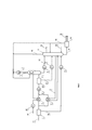
Установка включает входной сепаратор 1, дефлегматор 2, деметанизатор 3, рекуперационные теплообменники 4 и 5, редуцирующие устройства 6-9 (условно показаны детандеры), а также блок фракционирования 10.The installation includes an inlet separator 1, a reflux condenser, a
При работе установки (фиг. 1) сырой газ, подаваемый по линии 11, разделяют в сепараторе 1 на конденсат, выводимый по линии 12, и газ, который охлаждают в теплообменниках 4 и 5, редуцируют в устройстве 6 и направляют в дефлегматор 2, из которого по линии 13 выводят конденсат, а по линии 14 - газ дефлегмации. В деметанизатор 3 подают конденсаты, редуцированные в устройствах 8 и 9, а выводят: с верха по линии 15 -подготовленный газ, который смешивают с редуцированным в устройстве 7 газом дефлегмации, нагревают в теплообменной секции дефлегматора 2 и теплообменнике 4, из средней части по линии 16 - поток циркулирующего орошения, который нагревают в теплообменнике 5 и возвращают в деметанизатор 3, с низа деметанизатора 3 по линии 17 - деметанизированный конденсат, который направляют в блок фракционирования 10 для разделения на продукты, выводимые по линиям 18. Полученный отходящий газ по линии 19 возвращают в деметанизатор 3. Пунктиром показаны возможные: подача в линию 15 отходящего газа из линии 19, расположение перед дефлегматором 2 сепаратора 20 с линией 21 подачи конденсата в деметанизатор 3 с редуцирующим устройством 22, обогрев низа деметанизатора 3 тепловым потоком 23, отбор СПГ по линии 24 и сжатие подготовленного газа в компрессорной станции 25. Линии подачи ингибитора гидратообразования (метанола) и вывода его отработанного раствора условно не показаны.During the operation of the installation (Fig. 1), the raw gas supplied through
Таким образом, предлагаемая установка позволяет увеличить выход углеводородов С2+ и может найти применение в газовой промышленности.Thus, the proposed installation allows you to increase the yield of C 2+ hydrocarbons and can be used in the gas industry.
Claims (2)
Priority Applications (1)
| Application Number | Priority Date | Filing Date | Title |
|---|---|---|---|
| RU2019100124A RU2727503C1 (en) | 2019-01-09 | 2019-01-09 | Ltdr plant for complex wasteless preparation of gas |
Applications Claiming Priority (1)
| Application Number | Priority Date | Filing Date | Title |
|---|---|---|---|
| RU2019100124A RU2727503C1 (en) | 2019-01-09 | 2019-01-09 | Ltdr plant for complex wasteless preparation of gas |
Publications (1)
| Publication Number | Publication Date |
|---|---|
| RU2727503C1 true RU2727503C1 (en) | 2020-07-22 |
Family
ID=71741221
Family Applications (1)
| Application Number | Title | Priority Date | Filing Date |
|---|---|---|---|
| RU2019100124A RU2727503C1 (en) | 2019-01-09 | 2019-01-09 | Ltdr plant for complex wasteless preparation of gas |
Country Status (1)
| Country | Link |
|---|---|
| RU (1) | RU2727503C1 (en) |
Cited By (2)
| Publication number | Priority date | Publication date | Assignee | Title |
|---|---|---|---|---|
| US11577191B1 (en) | 2021-09-09 | 2023-02-14 | ColdStream Energy IP, LLC | Portable pressure swing adsorption method and system for fuel gas conditioning |
| US11717784B1 (en) | 2020-11-10 | 2023-08-08 | Solid State Separation Holdings, LLC | Natural gas adsorptive separation system and method |
Citations (3)
| Publication number | Priority date | Publication date | Assignee | Title |
|---|---|---|---|---|
| RU49609U1 (en) * | 2005-05-30 | 2005-11-27 | Общество с ограниченной ответственностью "Оренбурггазпром" (ООО "Оренбурггазпром") | INSTALLATION OF LOW-TEMPERATURE SEPARATION OF A HYDROCARBON GAS |
| US20100162753A1 (en) * | 2006-08-23 | 2010-07-01 | Eduard Coenraad Bras | Method and apparatus for treating a hydrocarbon stream |
| US9657246B2 (en) * | 2009-03-31 | 2017-05-23 | Keppel Offshore & Marine Technology Centre Pte Ltd | Process for natural gas liquefaction |
-
2019
- 2019-01-09 RU RU2019100124A patent/RU2727503C1/en active
Patent Citations (3)
| Publication number | Priority date | Publication date | Assignee | Title |
|---|---|---|---|---|
| RU49609U1 (en) * | 2005-05-30 | 2005-11-27 | Общество с ограниченной ответственностью "Оренбурггазпром" (ООО "Оренбурггазпром") | INSTALLATION OF LOW-TEMPERATURE SEPARATION OF A HYDROCARBON GAS |
| US20100162753A1 (en) * | 2006-08-23 | 2010-07-01 | Eduard Coenraad Bras | Method and apparatus for treating a hydrocarbon stream |
| US9657246B2 (en) * | 2009-03-31 | 2017-05-23 | Keppel Offshore & Marine Technology Centre Pte Ltd | Process for natural gas liquefaction |
Cited By (2)
| Publication number | Priority date | Publication date | Assignee | Title |
|---|---|---|---|---|
| US11717784B1 (en) | 2020-11-10 | 2023-08-08 | Solid State Separation Holdings, LLC | Natural gas adsorptive separation system and method |
| US11577191B1 (en) | 2021-09-09 | 2023-02-14 | ColdStream Energy IP, LLC | Portable pressure swing adsorption method and system for fuel gas conditioning |
Similar Documents
| Publication | Publication Date | Title |
|---|---|---|
| RU2668896C1 (en) | Plant for the deethanization of natural gas (options) | |
| CN102906232B (en) | Process for treating a stream of cracked gas coming from a hydrocarbon pyrolysis plant, and associated plant | |
| RU2382301C1 (en) | Unit for low-temperature separation of hydrocarbon gas | |
| RU2717668C1 (en) | Low-temperature fractionation unit for complex gas treatment and production of lng | |
| KR20200008559A (en) | Recovery of C2 + hydrocarbon streams from residual refinery gas and associated equipment | |
| RU2624652C1 (en) | Three-product gas treatment plant | |
| RU2727503C1 (en) | Ltdr plant for complex wasteless preparation of gas | |
| RU2732998C1 (en) | Low-temperature fractionation unit for complex gas treatment with production of liquefied natural gas | |
| RU2734237C1 (en) | Apparatus for complex gas treatment by low-temperature condensation | |
| CN109646980B (en) | Energy-saving device and method for fusel oil-free dividing wall column coupled with methanol multi-effect rectification | |
| RU2689737C1 (en) | Installation of ntdr for non-waste complex gas treatment | |
| RU2688533C1 (en) | Ltdr plant for integrated gas preparation and production of lng and its operation method | |
| RU2699913C1 (en) | Ltdr plant for integrated non-waste field gas treatment (versions) | |
| RU2736682C1 (en) | Natural gas preparation unit with helium extraction | |
| RU128923U1 (en) | INSTALLATION OF LOW-TEMPERATURE GAS CONDENSATION | |
| CN104246400B (en) | Fractionation process and associated apparatus for fractionation of cracked gas streams to obtain ethylene-rich fractions and fuel streams | |
| RU2705160C1 (en) | Unit of low-temperature dephlegmation with rectification ltdr for complex gas treatment with generation of lng | |
| RU2699912C1 (en) | Ltdr plant for production of hydrocarbons c2+ from main gas (versions) | |
| EP3240875B1 (en) | Method for improving propylene recovery from fluid catalytic cracker unit | |
| RU2730291C1 (en) | Low-temperature fractionation unit for complex gas treatment | |
| RU2743127C1 (en) | Plant for integrated gas preparation and production of liquefied natural gas by low-temperature fractionation | |
| RU2741026C2 (en) | Low-temperature dephlegmation unit with rectification for complex gas treatment and production of liquefied natural gas | |
| RU2685102C1 (en) | Apparatus for low-temperature dephlegmation with separation of ltds to prepare natural gas to obtain a propane-butane fraction | |
| RU2718074C1 (en) | Method of reconstruction of a low-temperature gas separation unit | |
| RU2446854C1 (en) | Method of de-ethanising of unstable gas condensate and plant to this end |