RU2710768C2 - Capsule, system for preparing drink suitable for drinking from similar capsule and use of such capsule in beverage preparation device - Google Patents
Capsule, system for preparing drink suitable for drinking from similar capsule and use of such capsule in beverage preparation device Download PDFInfo
- Publication number
- RU2710768C2 RU2710768C2 RU2017143834A RU2017143834A RU2710768C2 RU 2710768 C2 RU2710768 C2 RU 2710768C2 RU 2017143834 A RU2017143834 A RU 2017143834A RU 2017143834 A RU2017143834 A RU 2017143834A RU 2710768 C2 RU2710768 C2 RU 2710768C2
- Authority
- RU
- Russia
- Prior art keywords
- capsule
- specified
- flange
- wall
- end surface
- Prior art date
Links
Images


Classifications
-
- B—PERFORMING OPERATIONS; TRANSPORTING
- B65—CONVEYING; PACKING; STORING; HANDLING THIN OR FILAMENTARY MATERIAL
- B65D—CONTAINERS FOR STORAGE OR TRANSPORT OF ARTICLES OR MATERIALS, e.g. BAGS, BARRELS, BOTTLES, BOXES, CANS, CARTONS, CRATES, DRUMS, JARS, TANKS, HOPPERS, FORWARDING CONTAINERS; ACCESSORIES, CLOSURES, OR FITTINGS THEREFOR; PACKAGING ELEMENTS; PACKAGES
- B65D1/00—Containers having bodies formed in one piece, e.g. by casting metallic material, by moulding plastics, by blowing vitreous material, by throwing ceramic material, by moulding pulped fibrous material, by deep-drawing operations performed on sheet material
- B65D1/12—Cans, casks, barrels, or drums
- B65D1/14—Cans, casks, barrels, or drums characterised by shape
- B65D1/16—Cans, casks, barrels, or drums characterised by shape of curved cross-section, e.g. cylindrical
-
- A—HUMAN NECESSITIES
- A47—FURNITURE; DOMESTIC ARTICLES OR APPLIANCES; COFFEE MILLS; SPICE MILLS; SUCTION CLEANERS IN GENERAL
- A47J—KITCHEN EQUIPMENT; COFFEE MILLS; SPICE MILLS; APPARATUS FOR MAKING BEVERAGES
- A47J31/00—Apparatus for making beverages
- A47J31/24—Coffee-making apparatus in which hot water is passed through the filter under pressure, i.e. in which the coffee grounds are extracted under pressure
- A47J31/34—Coffee-making apparatus in which hot water is passed through the filter under pressure, i.e. in which the coffee grounds are extracted under pressure with hot water under liquid pressure
- A47J31/36—Coffee-making apparatus in which hot water is passed through the filter under pressure, i.e. in which the coffee grounds are extracted under pressure with hot water under liquid pressure with mechanical pressure-producing means
- A47J31/3604—Coffee-making apparatus in which hot water is passed through the filter under pressure, i.e. in which the coffee grounds are extracted under pressure with hot water under liquid pressure with mechanical pressure-producing means with a mechanism arranged to move the brewing chamber between loading, infusing and ejecting stations
- A47J31/3623—Cartridges being employed
-
- A—HUMAN NECESSITIES
- A47—FURNITURE; DOMESTIC ARTICLES OR APPLIANCES; COFFEE MILLS; SPICE MILLS; SUCTION CLEANERS IN GENERAL
- A47J—KITCHEN EQUIPMENT; COFFEE MILLS; SPICE MILLS; APPARATUS FOR MAKING BEVERAGES
- A47J31/00—Apparatus for making beverages
- A47J31/24—Coffee-making apparatus in which hot water is passed through the filter under pressure, i.e. in which the coffee grounds are extracted under pressure
- A47J31/34—Coffee-making apparatus in which hot water is passed through the filter under pressure, i.e. in which the coffee grounds are extracted under pressure with hot water under liquid pressure
- A47J31/36—Coffee-making apparatus in which hot water is passed through the filter under pressure, i.e. in which the coffee grounds are extracted under pressure with hot water under liquid pressure with mechanical pressure-producing means
- A47J31/3666—Coffee-making apparatus in which hot water is passed through the filter under pressure, i.e. in which the coffee grounds are extracted under pressure with hot water under liquid pressure with mechanical pressure-producing means whereby the loading of the brewing chamber with the brewing material is performed by the user
- A47J31/3676—Cartridges being employed
- A47J31/369—Impermeable cartridges being employed
-
- A—HUMAN NECESSITIES
- A47—FURNITURE; DOMESTIC ARTICLES OR APPLIANCES; COFFEE MILLS; SPICE MILLS; SUCTION CLEANERS IN GENERAL
- A47J—KITCHEN EQUIPMENT; COFFEE MILLS; SPICE MILLS; APPARATUS FOR MAKING BEVERAGES
- A47J31/00—Apparatus for making beverages
- A47J31/40—Beverage-making apparatus with dispensing means for adding a measured quantity of ingredients, e.g. coffee, water, sugar, cocoa, milk, tea
- A47J31/407—Beverage-making apparatus with dispensing means for adding a measured quantity of ingredients, e.g. coffee, water, sugar, cocoa, milk, tea with ingredient-containing cartridges; Cartridge-perforating means
-
- B—PERFORMING OPERATIONS; TRANSPORTING
- B01—PHYSICAL OR CHEMICAL PROCESSES OR APPARATUS IN GENERAL
- B01D—SEPARATION
- B01D11/00—Solvent extraction
- B01D11/02—Solvent extraction of solids
-
- B—PERFORMING OPERATIONS; TRANSPORTING
- B65—CONVEYING; PACKING; STORING; HANDLING THIN OR FILAMENTARY MATERIAL
- B65D—CONTAINERS FOR STORAGE OR TRANSPORT OF ARTICLES OR MATERIALS, e.g. BAGS, BARRELS, BOTTLES, BOXES, CANS, CARTONS, CRATES, DRUMS, JARS, TANKS, HOPPERS, FORWARDING CONTAINERS; ACCESSORIES, CLOSURES, OR FITTINGS THEREFOR; PACKAGING ELEMENTS; PACKAGES
- B65D1/00—Containers having bodies formed in one piece, e.g. by casting metallic material, by moulding plastics, by blowing vitreous material, by throwing ceramic material, by moulding pulped fibrous material, by deep-drawing operations performed on sheet material
- B65D1/22—Boxes or like containers with side walls of substantial depth for enclosing contents
- B65D1/26—Thin-walled containers, e.g. formed by deep-drawing operations
-
- B—PERFORMING OPERATIONS; TRANSPORTING
- B65—CONVEYING; PACKING; STORING; HANDLING THIN OR FILAMENTARY MATERIAL
- B65D—CONTAINERS FOR STORAGE OR TRANSPORT OF ARTICLES OR MATERIALS, e.g. BAGS, BARRELS, BOTTLES, BOXES, CANS, CARTONS, CRATES, DRUMS, JARS, TANKS, HOPPERS, FORWARDING CONTAINERS; ACCESSORIES, CLOSURES, OR FITTINGS THEREFOR; PACKAGING ELEMENTS; PACKAGES
- B65D1/00—Containers having bodies formed in one piece, e.g. by casting metallic material, by moulding plastics, by blowing vitreous material, by throwing ceramic material, by moulding pulped fibrous material, by deep-drawing operations performed on sheet material
- B65D1/40—Details of walls
- B65D1/42—Reinforcing or strengthening parts or members
-
- B—PERFORMING OPERATIONS; TRANSPORTING
- B65—CONVEYING; PACKING; STORING; HANDLING THIN OR FILAMENTARY MATERIAL
- B65D—CONTAINERS FOR STORAGE OR TRANSPORT OF ARTICLES OR MATERIALS, e.g. BAGS, BARRELS, BOTTLES, BOXES, CANS, CARTONS, CRATES, DRUMS, JARS, TANKS, HOPPERS, FORWARDING CONTAINERS; ACCESSORIES, CLOSURES, OR FITTINGS THEREFOR; PACKAGING ELEMENTS; PACKAGES
- B65D17/00—Rigid or semi-rigid containers specially constructed to be opened by cutting or piercing, or by tearing of frangible members or portions
-
- B—PERFORMING OPERATIONS; TRANSPORTING
- B65—CONVEYING; PACKING; STORING; HANDLING THIN OR FILAMENTARY MATERIAL
- B65D—CONTAINERS FOR STORAGE OR TRANSPORT OF ARTICLES OR MATERIALS, e.g. BAGS, BARRELS, BOTTLES, BOXES, CANS, CARTONS, CRATES, DRUMS, JARS, TANKS, HOPPERS, FORWARDING CONTAINERS; ACCESSORIES, CLOSURES, OR FITTINGS THEREFOR; PACKAGING ELEMENTS; PACKAGES
- B65D85/00—Containers, packaging elements or packages, specially adapted for particular articles or materials
- B65D85/70—Containers, packaging elements or packages, specially adapted for particular articles or materials for materials not otherwise provided for
- B65D85/804—Disposable containers or packages with contents which are mixed, infused or dissolved in situ, i.e. without having been previously removed from the package
- B65D85/8043—Packages adapted to allow liquid to pass through the contents
- B65D85/8046—Pods, i.e. closed containers made only of filter paper or similar material
-
- B—PERFORMING OPERATIONS; TRANSPORTING
- B65—CONVEYING; PACKING; STORING; HANDLING THIN OR FILAMENTARY MATERIAL
- B65D—CONTAINERS FOR STORAGE OR TRANSPORT OF ARTICLES OR MATERIALS, e.g. BAGS, BARRELS, BOTTLES, BOXES, CANS, CARTONS, CRATES, DRUMS, JARS, TANKS, HOPPERS, FORWARDING CONTAINERS; ACCESSORIES, CLOSURES, OR FITTINGS THEREFOR; PACKAGING ELEMENTS; PACKAGES
- B65D85/00—Containers, packaging elements or packages, specially adapted for particular articles or materials
- B65D85/70—Containers, packaging elements or packages, specially adapted for particular articles or materials for materials not otherwise provided for
- B65D85/804—Disposable containers or packages with contents which are mixed, infused or dissolved in situ, i.e. without having been previously removed from the package
- B65D85/8043—Packages adapted to allow liquid to pass through the contents
- B65D85/8064—Sealing means for the interface with the processing machine
-
- Y—GENERAL TAGGING OF NEW TECHNOLOGICAL DEVELOPMENTS; GENERAL TAGGING OF CROSS-SECTIONAL TECHNOLOGIES SPANNING OVER SEVERAL SECTIONS OF THE IPC; TECHNICAL SUBJECTS COVERED BY FORMER USPC CROSS-REFERENCE ART COLLECTIONS [XRACs] AND DIGESTS
- Y02—TECHNOLOGIES OR APPLICATIONS FOR MITIGATION OR ADAPTATION AGAINST CLIMATE CHANGE
- Y02W—CLIMATE CHANGE MITIGATION TECHNOLOGIES RELATED TO WASTEWATER TREATMENT OR WASTE MANAGEMENT
- Y02W30/00—Technologies for solid waste management
- Y02W30/50—Reuse, recycling or recovery technologies
- Y02W30/80—Packaging reuse or recycling, e.g. of multilayer packaging
Abstract
Description
Изобретение относится к капсуле согласно ограничительной части пункта 1 формулы изобретения.The invention relates to a capsule according to the restrictive part of
Изобретение также относится к системе для приготовления пригодного для питья напитка согласно ограничительной части пункта 37 формулы изобретения и к применению подобной капсулы.The invention also relates to a system for preparing a drinkable drink according to the preamble of paragraph 37 of the claims and to the use of such a capsule.
Подобная капсула, подобная система и подобное применение известны из документа ЕР-В-1 700 548, в котором раскрыта капсула, выполненная с уплотнительной конструкцией, имеющей форму уступа, то есть с резким увеличением диаметра боковой стенки капсулы, и охватывающий элемент данной известной системы имеет уплотняющую поверхность, воздействующую на уплотнительную конструкцию для обеспечения изгибания уплотнительной конструкции, при этом уплотняющая поверхность имеет такой наклон, что изгибание уплотнительной конструкции представляет собой деформацию уступа в направлении внутрь и вниз. Кроме того, в известной системе охватывающий элемент содержит капсулодержатель и управляемый вручную или автоматический механизм для смещения охватывающего элемента и капсулодержателя друг относительно друга. Управляемый вручную или автоматический механизм обеспечивает приложение силы к уплотнительной конструкции капсулы, когда охватывающий элемент закрывается на капсулодержателе. Данная сила должна гарантировать герметичное уплотнение между охватывающим элементом и капсулой. Поскольку управляемый вручную или автоматический механизм выполнен с возможностью перемещения относительно основания, уплотняющие способности системы могут зависеть от давления текучей среды, нагнетаемой средством нагнетания текучей среды. Если давление текучей среды увеличивается, сила между уплотнительной конструкцией капсулы и свободным концом охватывающего элемента также увеличивается. Подобная система описана ниже. Уплотнительная конструкция капсулы должна быть выполнена так, что при достижении максимального давления текучей среды в охватывающем элементе уплотнительная конструкция должна по-прежнему обеспечивать уплотняющий по отношению к текучей среде контакт между охватывающим элементом и капсулой. Однако уплотнительная конструкция также должна быть выполнена так, чтобы перед варкой или в начале варки, когда давление текучей среды в охватывающем элементе снаружи капсулы является сравнительно низким, уплотнительная конструкция также обеспечивала уплотняющий контакт между охватывающим элементом и капсулой. Если в начале варки будет отсутствовать уплотняющий контакт между капсулой и охватывающим элементом, будет возникать утечка. Однако, если происходит утечка, существует реальная вероятность того, что давление в охватывающем элементе и снаружи капсулы не будет увеличиваться в достаточной степени для увеличения силы, действующей на уплотнительную конструкцию посредством свободного конца охватывающего элемента, если управляемый вручную или автоматический механизм обеспечивает перемещение охватывающего элемента к капсулодержателю. Только в том случае, если имеется достаточное исходное уплотнение, давление в охватывающем элементе будет увеличиваться, в результате чего также будет увеличиваться сила, действующая со стороны свободного конца охватывающего элемента на уплотнительную конструкцию капсулы для обеспечения достаточного уплотняющего контакта также при повышенном давлении текучей среды. Кроме того, данное повышенное давление текучей среды снаружи капсулы также обеспечивает увеличенное давление текучей среды внутри капсулы, что является существенным, если капсула снабжена крышкой, которая выполнена с возможностью разрыва на рельефных элементах капсулодержателя (также называемого экстракционной пластиной) устройства для приготовления напитков под действием давления текучей среды в капсуле.A similar capsule, a similar system, and similar use are known from EP-B-1 700 548, which discloses a capsule made with a sealing structure having a step shape, that is, with a sharp increase in the diameter of the side wall of the capsule, and the female element of this known system has a sealing surface acting on the sealing structure to allow bending of the sealing structure, wherein the sealing surface has such a slope that the bending of the sealing structure is deformation of the ledge inward and downward. In addition, in the known system, the female member comprises a capsule holder and a manually or automatically controlled mechanism for biasing the female member and capsule holder relative to each other. A manually controlled or automatic mechanism provides a force to the sealing structure of the capsule when the enclosing member closes on the capsule holder. This force should ensure a tight seal between the female member and the capsule. Since a manually controlled or automatic mechanism is movable relative to the base, the sealing capabilities of the system may depend on the pressure of the fluid pumped by the fluid injection means. If the fluid pressure increases, the force between the sealing structure of the capsule and the free end of the female element also increases. A similar system is described below. The sealing structure of the capsule must be designed such that when maximum fluid pressure is reached in the female member, the sealing structure should still provide fluid sealing contact between the female member and the capsule. However, the sealing structure should also be designed so that before cooking or at the beginning of cooking, when the fluid pressure in the enclosing member outside the capsule is relatively low, the sealing design also provided sealing contact between the enclosing member and the capsule. If at the beginning of cooking there is no sealing contact between the capsule and the female member, a leak will occur. However, if a leak occurs, there is a real possibility that the pressure in the enclosing member and on the outside of the capsule will not increase sufficiently to increase the force acting on the sealing structure through the free end of the enclosing member if the manually controlled or automatic mechanism allows the enclosing member to move toward capsule holder. Only if there is a sufficient initial seal, the pressure in the female element will increase, as a result of which the force exerted by the free end of the female element on the sealing structure of the capsule will also increase to ensure sufficient sealing contact even with increased fluid pressure. In addition, this increased fluid pressure outside the capsule also provides increased fluid pressure inside the capsule, which is essential if the capsule is provided with a cap that is capable of bursting on the relief elements of the capsule holder (also called extraction plate) of the pressure beverage device fluid in the capsule.
Из вышеизложенного следует, что уплотнительная конструкция представляет собой элемент, конструкция которого имеет очень важное значение. Она должна обеспечивать возможность создания уплотняющего контакта между охватывающим элементом и капсулой при сравнительно низком давлении текучей среды, если только сравнительно небольшая сила приложена к уплотнительной конструкции посредством свободного конца охватывающего элемента, но она также должна обеспечивать уплотняющий контакт при значительно более высоком давлении текучей среды в охватывающем элементе снаружи капсулы, если бóльшая сила приложена посредством свободного конца охватывающего элемента к уплотнительной конструкции капсулы. В частности, когда кольцевая торцевая поверхность охватывающего элемента выполнена с проходящими в радиальном направлении, открытыми канавками, которые служат в качестве канала для впуска воздуха при прекращении действия силы между охватывающим элементом и капсулодержателем так, чтобы пользователю было легче извлечь капсулу, уплотнительная конструкция также должна обладать способностью «закрывать» проходящие в радиальном направлении, открытые канавки для обеспечения эффективного уплотнения.From the foregoing, it follows that the sealing structure is an element whose design is very important. It should provide the possibility of creating a sealing contact between the female member and the capsule at a relatively low fluid pressure, if only a relatively small force is applied to the sealing structure by the free end of the female element, but it should also provide sealing contact with a significantly higher fluid pressure in the female element outside the capsule, if a greater force is applied by means of the free end of the female element to the sealing For instructions capsules. In particular, when the annular end surface of the enclosing member is formed with radially extending open grooves that serve as an air inlet channel when the force between the enclosing member and the capsule holder ceases to be easier to remove, the sealing structure must also have the ability to "close" open, radially extending grooves to ensure effective compaction.
Из WO2012/120459 известна капсула, в которой уплотнительная конструкция включает в себя деформируемую часть выступающего наружу фланца корпуса капсулы. Однако для гарантирования того, что уплотнительная кольцевая часть обеспечит уплотняющий контакт относительно кольцевой торцевой поверхности охватывающего элемента при ее деформировании между данной кольцевой поверхностью и закрывающим элементом, кольцевая торцевая поверхность охватывающего элемента имеет средства деформирования в виде неглубокой канавки с закруглением, проходящей в направлении вдоль окружности кольцевой поверхности. При функционировании неглубокая канавка с закруглением гарантирует то, что выступающее вверх ребро деформируемой части будет загибаться внутрь. Соответственно, надежное функционирование подобных капсул будет гарантировано только при применении в определенных устройствах для приготовления напитков.A capsule is known from WO2012 / 120459, in which the sealing structure includes a deformable part of the protruding outward flange of the capsule body. However, to ensure that the sealing ring portion provides sealing contact with respect to the annular end surface of the enclosing member when it is deformed between the given annular surface and the closure member, the annular end surface of the enclosing member has deformation means in the form of a shallow groove with a rounding extending in the direction along the circumference of the annular surface. During operation, a shallow groove with a rounding ensures that the upwardly extending rib of the deformable part will bend inward. Accordingly, the reliable functioning of such capsules will be guaranteed only when used in certain devices for preparing drinks.
Задача изобретения состоит в разработке капсулы, которая надежно плотно прижимается к кольцевой торцевой поверхности охватывающего элемента устройства для приготовления напитков, если капсула установлена в заданном положении в охватывающем элементе устройства для приготовления напитков и охватывающий элемент закрыт посредством закрывающего элемента устройства для приготовления напитков, такого как экстракционная пластина устройства для приготовления напитков, при этом часть выступающего наружу фланца капсулы и уплотнительная конструкция капсулы зажимаются между кольцевой торцевой поверхностью охватывающего элемента и закрывающим элементом устройства для приготовления напитков даже в случае охватывающего элемента, кольцевая торцевая поверхность которого выполнена с проходящими в радиальном направлении, открытыми канавкам, и которая может по-прежнему изготавливаться с низкими затратами и является экологически безопасной и легко поддается рециклингу после избавления от капсулы после использования. Во многих известных капсулах уплотнительный элемент выполнен из упругого материала, такого как резиновый упругий материал, более конкретно, такого как силиконовый материал, который после использования должен быть отделен от алюминиевого основания и крышки в целях рециклинга.An object of the invention is to provide a capsule which is firmly pressed against the annular end surface of a female element of a beverage preparation device if the capsule is installed in a predetermined position in the female element of the beverage device and the female element is closed by the closing element of the beverage device, such as extraction the plate of the device for preparing drinks, while part of the protruding outward flange of the capsule and sealing to The capsule design is clamped between the annular end surface of the enclosing member and the closure of the beverage preparation device even in the case of the enclosing member, the annular end surface of which is provided with radially extending, open grooves and which can still be manufactured at low cost and is environmentally friendly and easy to recycle after disposing of the capsule after use. In many known capsules, the sealing element is made of an elastic material, such as a rubber elastic material, more specifically, such as silicone material, which after use must be separated from the aluminum base and lid for recycling purposes.
Данная задача решается посредством выполнения капсулы согласно пункту 1 формулы изобретения.This problem is solved by performing the capsule according to
Поскольку уплотнительная конструкция включает в себя деформируемую уплотнительную кольцевую часть фланца, при этом уплотнительная кольцевая часть выступает в аксиальном направлении от базовых частей фланца со стороны базовых частей, противоположной по отношению к крышке, уплотнительная конструкция составляет одно целое с фланцем капсулы, так что капсула может быть изготовлена быстро с низкими затратами, и алюминиевый корпус капсулы может быть легко подвергнут рециклингу. В данном контексте значение термина «алюминиевый» следует понимать, как охватывающее также алюминиевый сплав.Since the sealing structure includes a deformable sealing ring part of the flange, while the sealing ring part protrudes axially from the base parts of the flange from the side of the base parts opposite to the lid, the sealing structure is integral with the capsule flange so that the capsule can be fabricated quickly at low cost, and the aluminum capsule body can be easily recycled. In this context, the meaning of the term "aluminum" should be understood as covering also an aluminum alloy.
Поскольку верхняя часть соединяющей части, наиболее удаленная в аксиальном направлении от базовых частей фланца, является плоской или имеет центральную плоскость, изогнутую с радиусом кривизны, превышающим более чем в два раза толщину стенки указанной верхней части соединяющей части, соединяющая часть может легко деформироваться локально при малом усилии зажима для адаптации к форме кольцевой торцевой поверхности охватывающего элемента, когда соединяющая часть зажата между кольцевой торцевой поверхностью охватывающего элемента и закрывающим элементом. Даже в случае охватывающего элемента, кольцевая торцевая поверхность которого выполнена с проходящими в радиальном направлении, открытыми канавками, уплотнительная конструкция может адаптироваться к последовательности выступов и углублений в направлении вдоль окружности, образованных на кольцевой торцевой поверхности охватывающего элемента, и эффективно плотно прижиматься также к заглубленным поверхностным участкам кольцевой торцевой поверхности уже во время ранней стадии закрывания охватывающего элемента, когда усилие зажима, с которым охватывающий элемент и закрывающий элемент прижимаются друг к другу, является сравнительно небольшим.Since the upper part of the connecting part, the farthest in the axial direction from the base parts of the flange, is flat or has a central plane curved with a radius of curvature more than two times the wall thickness of the specified upper part of the connecting part, the connecting part can easily be deformed locally at small clamping forces to adapt to the shape of the annular end surface of the enclosing member when the connecting part is sandwiched between the annular end surface of the enclosing member and kryvayuschim element. Even in the case of a female element, the annular end surface of which is made with radially extending open grooves, the sealing structure can adapt to the sequence of protrusions and recesses in the circumferential direction formed on the annular end surface of the female element, and can also be effectively pressed against the recessed surface sections of the annular end surface already during the early stage of closing of the enclosing element, when the clamping force, which covering element and the closing element are pressed together, it is relatively small.
Следует отметить, что для того, чтобы уплотнение между кольцевой торцевой поверхностью охватывающего элемента и уплотнительной кольцевой частью фланца было эффективным для гарантирования того, что перепад давлений на веществе в капсуле будет достаточным для желательного процесса приготовления напитка, оно необязательно должно быть герметично непроницаемым при всех обстоятельствах. При утечке жидкости до 4% и, предпочтительно, не выше 2,5% от объема жидкости, нагнетаемой через капсулу, уплотнение по-прежнему будет эффективным для того, чтобы устройство для приготовления напитков могло создавать заданный перепад давлений на веществе. Соответственно, уплотнение, допускающее подобную утечку, представляет собой эффективное уплотнение.It should be noted that in order for the seal between the annular end surface of the enclosing member and the sealing annular part of the flange to be effective in order to ensure that the pressure drop across the substance in the capsule is sufficient for the desired beverage preparation process, it need not necessarily be hermetically impermeable under all circumstances . With a liquid leak of up to 4% and preferably not higher than 2.5% of the volume of liquid pumped through the capsule, the seal will still be effective so that the beverage preparation device can create a predetermined pressure drop across the substance. Accordingly, a leak-tight seal is an effective seal.
Изобретение также может быть реализовано в системе согласно пункту 37 формулы изобретения и в применении согласно пункту 47 формулы изобретения. При функционировании такой системы и при таком применении соединяющая часть легко локально деформируется, адаптируясь тем самым к форме кольцевой торцевой поверхности охватывающего элемента, когда она зажимается между кольцевой торцевой поверхностью охватывающего элемента и закрывающим элементом. Более конкретно, уплотнительная конструкция адаптируется к последовательности выступов и углублений в направлении вдоль окружности, образованных на кольцевой торцевой поверхности охватывающего элемента, и эффективно плотно прижимается также к заглубленным поверхностным участкам кольцевой торцевой поверхности уже во время ранней стадии закрывания охватывающего элемента, когда усилие зажима, с которым охватывающий элемент и закрывающий элемент прижимаются друг к другу, является сравнительно небольшим.The invention can also be implemented in the system according to paragraph 37 of the claims and in use according to
Хорошая прилегаемость к форме кольцевой торцевой поверхности и, соответственно, особенно эффективное и надежное уплотнение уже при низком давлении уплотнения могут быть обеспечены, если по меньшей мере участок верхней части соединяющей части имеет уменьшенную толщину стенки, которая меньше толщины стенки внутренней и наружной стеночных частей.Good fit to the shape of the annular end surface and, accordingly, a particularly effective and reliable seal even at low sealing pressure can be achieved if at least a portion of the upper part of the connecting part has a reduced wall thickness that is less than the wall thickness of the inner and outer wall parts.
Если корпус капсулы имеет покрытие на по меньшей мере одной стороне, отсутствие покрытия на по меньшей мере участке верхней части соединяющей части, имеющем уменьшенную толщину стенки, уменьшает риск повреждения или отслаивания покрытия при сравнительно больших деформациях, имеющих место, когда толщину стенки уменьшают во время изготовления. Покрытие также может быть удалено в процессе уменьшения толщины стенки во время изготовления, например, если уменьшение толщины стенки предусматривает съем материала стенки.If the capsule body has a coating on at least one side, the absence of coating on at least a portion of the upper part of the connecting part having a reduced wall thickness reduces the risk of damage or flaking of the coating during the relatively large deformations that occur when the wall thickness is reduced during manufacture . The coating can also be removed in the process of reducing the wall thickness during manufacture, for example, if reducing the wall thickness involves removal of the wall material.
Дополнительно улучшенный уплотняющий эффект может быть достигнут, если не имеющий покрытия участок соединяющей части находится со стороны фланца, противоположной по отношению к крышке, и имеет текстурированную поверхность. Текстура на поверхности может дополнительно улучшить прилегаемость по время ранних стадий зажима, когда давление уплотнения является еще низким, поскольку усилие зажима передается только через выступающие части текстуры, так что на выступающих частях будет действовать более высокое контактное давление, чем действовало бы на полностью гладкой поверхности контакта.An additionally improved sealing effect can be achieved if the uncoated portion of the connecting portion is on the flange side opposite to the cap and has a textured surface. The texture on the surface can further improve the fit during the early stages of the clamping, when the sealing pressure is still low, since the clamping force is transmitted only through the protruding parts of the texture, so that the protruding parts will have a higher contact pressure than would act on a completely smooth contact surface .
Особенно улучшенный уплотняющий эффект может быть достигнут, если текстурированная поверхность включает в себя гребнеобразные выступы и впадины, проходящие в направлении вдоль окружности фланца, поскольку при этом раннее соответствие по форме по отношению к форме кольцевой торцевой поверхности обеспечивается в по существу кольцевых зонах или кольцевых секторах, проходящих в основном в направлении вдоль окружности.A particularly improved sealing effect can be achieved if the textured surface includes ridge-shaped protrusions and depressions extending in the direction along the circumference of the flange, since early matching in shape with respect to the shape of the annular end surface is ensured in essentially annular zones or annular sectors, passing mostly in a circumferential direction.
Изобретение также может быть реализовано в способе согласно пункту 52 формулы изобретения, представляющем собой способ изготовления подобной капсулы. Покрытие эффективно удаляют с той части фланца, толщина стенки которой должна быть уменьшена, перед уменьшением или во время уменьшения толщины стенки.The invention can also be implemented in the method according to paragraph 52 of the claims, which is a method of manufacturing such a capsule. The coating is effectively removed from that part of the flange whose wall thickness is to be reduced before or during the reduction of the wall thickness.
Особенно эффективное уменьшение толщины стенки при изготовлении может быть обеспечено, если покрытие удаляют с той части фланца, толщина стенки которой должна быть уменьшена, во время этапа съема материала для съема материала стенки для уменьшения толщины стенки.A particularly effective reduction in wall thickness during manufacture can be achieved if the coating is removed from that part of the flange whose wall thickness is to be reduced during the material removal step to remove the wall material to reduce the wall thickness.
Однако покрытие на верхней части соединяющей части, или такое же покрытие, как на остальной части наружной поверхности корпуса капсулы, или покрытие, отличающееся от покрытия на остальной части наружной поверхности корпуса капсулы, может также улучшить уплотнение, например, за счет уменьшения трения между кольцевой торцевой поверхностью охватывающего элемента и участком поверхности уплотнительной кольцевой части, находящимся в контакте с кольцевой торцевой поверхностью, что способствует адаптации уплотнительной кольцевой части, находящейся в контакте с кольцевой торцевой поверхностью, к форме кольцевой торцевой поверхности.However, a coating on the upper part of the connecting part, or a same coating as on the rest of the outer surface of the capsule body, or a coating different from the coating on the rest of the outer surface of the capsule body, can also improve compaction, for example, by reducing friction between the annular end the surface of the enclosing element and the surface portion of the sealing annular part in contact with the annular end surface, which contributes to the adaptation of the sealing annular part, dyascheysya in contact with the annular end surface to form the annular end surface.
Если одна из внутренней и наружной стеночных частей ориентирована под углом относительно базовых частей фланца, отличным от угла другой из внутренней и наружной стеночных частей, может быть обеспечено точное и надежное деформирование уплотнительной конструкции в соответствии с заданной формой во время уплотнения. В частности, это противодействует возникновению переходных зон между окружными частями, деформирующимися до разных конечных форм, что влечет за собой повышенный риск утечки.If one of the inner and outer wall parts is oriented at an angle relative to the base parts of the flange, different from the angle of the other of the inner and outer wall parts, accurate and reliable deformation of the sealing structure in accordance with a given shape during sealing can be ensured. In particular, this counteracts the occurrence of transition zones between the circumferential parts, deforming to different final shapes, which entails an increased risk of leakage.
Данный эффект может быть обеспечен особенно действенно, если одна из внутренней и наружной стеночных частей проходит под непрямым углом, предпочтительно составляющим 20-60° и более предпочтительно, 30-50°, относительно плоскости соответствующей смежной базовой части фланца, и другая из внутренней и наружной стеночных частей проходит от соответствующей смежной базовой части фланца под бóльшим или противоположным углом, предпочтительно составляющим 60-160° и, более предпочтительно, 70-150°, относительно плоскости соответствующей смежной базовой части фланца.This effect can be achieved especially effectively if one of the inner and outer wall parts extends at an indirect angle, preferably 20-60 ° and more preferably 30-50 °, relative to the plane of the corresponding adjacent base part of the flange, and the other of the inner and outer wall parts extends from the corresponding adjacent base part of the flange at a greater or opposite angle, preferably comprising 60-160 ° and, more preferably, 70-150 °, relative to the plane of the corresponding adjacent base flange portion.
Для плавного, точного и надежного деформирования до заданной формы предпочтительно, если в сечении по меньшей мере участок по меньшей мере одной из внутренней и наружной стеночных частей имеет изогнутую центральную плоскость, в частности, если криволинейный участок данной по меньшей мере одной из внутренней и наружной стеночных частей граничит с кривизной верхней части указанной соединяющей части, и если в сечении деформируемая часть является Ω-образной. Другое преимущество Ω-образной формы состоит в том, что остается только небольшой зазор между внутренней и наружной базовыми частями фланца, так что остается большая площадь поверхности для прилипания крышки к фланцу.For smooth, accurate and reliable deformation to a given shape, it is preferable if at least a section of at least one of the inner and outer wall parts has a curved central plane in cross section, in particular, if the curved section of this at least one of the inner and outer wall parts borders on the curvature of the upper part of the specified connecting part, and if in the cross section the deformable part is Ω-shaped. Another advantage of the Ω-shape is that there is only a small gap between the inner and outer base parts of the flange, so that a large surface area remains for the cover to adhere to the flange.
Для обеспечения высокого противодавления во время конечной стадии деформирования уплотнительной конструкции может быть предусмотрен опорный элемент между внутренней и наружной стеночными частями.To provide high back pressure during the final stage of deformation of the sealing structure, a support member may be provided between the inner and outer wall portions.
Особенная легкая адаптация к форме кольцевой торцевой поверхности может быть обеспечена, если верхняя часть соединяющей части расположена так, что кольцевая торцевая часть сначала контактирует с данной верхней частью при зажиме уплотнительной кольцевой части между кольцевой торцевой поверхностью и закрывающим элементом совместимого устройства для приготовления напитков.Particularly easy adaptation to the shape of the annular end surface can be achieved if the upper part of the connecting part is arranged so that the annular end part first contacts this upper part when the sealing ring part is clamped between the annular end surface and the closure of a compatible beverage preparation device.
Верхняя часть соединяющей части образует скругленный или плоский гребень, проходящий в направлении вдоль окружности вокруг осевой линии капсулы. При обеспечении того, чтобы гребень, образованный верхней частью соединяющей части, имел диаметр 29-33 мм, более предпочтительно, 30,0-31,4 мм и, наиболее предпочтительно, 30,3-31,0 мм, верхняя часть соединяющей части будет расположена центрально относительно кольцевой торцевой поверхности для контактирования сначала с центральной частью указанной кольцевой торцевой поверхности, когда уплотнительная кольцевая часть зажимается между кольцевой торцевой поверхностью и указанным закрывающим элементом широко используемых и промышленно изготавливаемых и имеющихся на рынке устройств для приготовления напитков, таких как Citiz, Lattisima, U, Maestria, Pixie, Inissia и Essenza.The upper part of the connecting part forms a rounded or flat ridge extending in a circumferential direction around the center line of the capsule. While ensuring that the ridge formed by the upper part of the connecting part has a diameter of 29-33 mm, more preferably 30.0-31.4 mm and, most preferably, 30.3-31.0 mm, the upper part of the connecting part will be located centrally relative to the annular end surface for contacting first with the Central part of the specified annular end surface, when the sealing ring part is clamped between the annular end surface and the specified closing element is widely used and industrially manufactured proxy and on the market for beverage preparation devices, such as Citiz, Lattisima, U, Maestria, Pixie, Inissia and Essenza.
Изобретение в особенности предпочтительно, когда в варианте выполнения капсулы капсула заполнена 5-20 граммами, предпочтительно, 5-10 граммами, более предпочтительно, 5-7 граммами экстрагируемого продукта, такого как обжаренный и молотый кофе.The invention is particularly preferred when, in an embodiment of the capsule, the capsule is filled with 5-20 grams, preferably 5-10 grams, more preferably 5-7 grams of extractable product, such as roasted and ground coffee.
В варианте выполнения капсулы согласно изобретению, который особенно прост в изготовлении, наружный диаметр выступающего наружу фланца капсулы превышает диаметр нижней части капсулы. Наружный диаметр выступающего наружу фланца предпочтительно составляет приблизительно 37,1 мм, и диаметр нижней части капсулы составляет приблизительно 23,3 мм.In an embodiment of the capsule according to the invention, which is particularly simple to manufacture, the outer diameter of the protruding outward flange of the capsule exceeds the diameter of the lower part of the capsule. The outer diameter of the protruding outward flange is preferably approximately 37.1 mm, and the diameter of the lower part of the capsule is approximately 23.3 mm.
Изобретение особенно предпочтительно, когда в варианте выполнения капсулы толщина алюминиевого корпуса капсулы составляет 20-200 микрон, предпочтительно, 100 микрон.The invention is particularly preferred when, in an embodiment of the capsule, the thickness of the aluminum capsule body is 20-200 microns, preferably 100 microns.
Изобретение особенно предпочтительно, когда в варианте выполнения капсулы толщина алюминиевой крышки составляет 15-65 микрон, предпочтительно, 30-45 микрон и, более предпочтительно, 39 микрон.The invention is particularly preferred when, in an embodiment of the capsule, the thickness of the aluminum cap is 15-65 microns, preferably 30-45 microns, and more preferably 39 microns.
В одном варианте выполнения капсулы согласно изобретению толщина алюминиевой крышки меньше толщины алюминиевого корпуса капсулы.In one embodiment of the capsule of the invention, the thickness of the aluminum cap is less than the thickness of the aluminum capsule body.
В дополнительном варианте выполнения капсулы согласно изобретению алюминиевая крышка выполнена с возможностью разрыва на закрывающем элементе устройства для приготовления напитков, таком как экстракционная пластина устройства для приготовления напитков, под действием давления текучей среды в капсуле.In a further embodiment of the capsule according to the invention, the aluminum cap is capable of tearing on the closure element of the beverage preparation device, such as an extraction plate of the beverage preparation device, by the pressure of the fluid in the capsule.
В одном варианте выполнения капсулы согласно изобретению, который особенно прост в изготовлении, боковая стенка алюминиевого корпуса капсулы имеет свободный конец, противоположный нижней части, при этом выступающий наружу фланец выступает от указанного свободного конца боковой стенки в направлении по меньшей мере по существу поперечном к центральной оси корпуса капсулы. Выступающий наружу фланец предпочтительно содержит закрученную наружную кромку, которая предпочтительна для обеспечения достаточного уплотнения относительно кольцевой торцевой поверхности, выполненной с проходящими в радиальном направлении открытыми канавками. Радиус внутреннего края закрученной наружной кромки выступающего наружу фланца относительно центральной оси корпуса капсулы предпочтительно составляет по меньшей мере 32 мм, так что обеспечивается зазор от кольцевой торцевой поверхности охватывающего элемента. При этом предпочтительно, чтобы уплотнительная конструкция была расположена между свободным концом боковой стенки алюминиевого корпуса капсулы и внутренним краем закрученной наружной кромки выступающего наружу фланца для получения еще более удовлетворительного уплотнения.In one embodiment of the capsule according to the invention, which is particularly simple to manufacture, the side wall of the aluminum capsule body has a free end opposite the lower part, the outwardly protruding flange protrudes from said free end of the side wall in a direction at least substantially transverse to the central axis capsule body. The protruding outward flange preferably comprises a curled outer edge, which is preferable to provide sufficient sealing relative to the annular end surface made with radially extending open grooves. The radius of the inner edge of the swirling outer edge of the protruding outward flange relative to the central axis of the capsule body is preferably at least 32 mm, so that a clearance is provided from the annular end surface of the enclosing member. In this case, it is preferable that the sealing structure is located between the free end of the side wall of the aluminum capsule body and the inner edge of the twisted outer edge of the protruding outward flange to obtain an even more satisfactory seal.
Для гарантирования того, что закрученная наружная кромка не будет мешать работе самых разных промышленно изготавливаемых и имеющихся на рынке и будущих устройств для приготовления напитков, выступающий наружу фланец имеет наибольший размер в радиальном сечении, составляющий приблизительно 1,2 миллиметра.To ensure that the curled outer edge does not interfere with the work of a wide variety of industrially manufactured and commercially available and future beverage preparation devices, the outwardly extending flange has the largest radial cross-sectional dimension of approximately 1.2 millimeters.
Изобретение особенно предпочтительно для капсул, у которых внутренний диаметр свободного конца боковой стенки алюминиевого корпуса капсулы составляет приблизительно 29,5 мм. Расстояние между свободным концом боковой стенки алюминиевого корпуса капсулы и самым дальним от центра краем выступающего наружу фланца может составлять приблизительно 3,8 миллиметра. Предпочтительная высота алюминиевого корпуса капсулы составляет приблизительно 28,4 мм.The invention is particularly preferred for capsules in which the inner diameter of the free end of the side wall of the aluminum capsule body is approximately 29.5 mm. The distance between the free end of the side wall of the aluminum capsule body and the outermost edge of the protruding outward flange may be approximately 3.8 millimeters. The preferred height of the aluminum capsule body is approximately 28.4 mm.
В одном варианте выполнения капсулы согласно изобретению, которую пользователю после использования легче извлекать из устройства для приготовления напитков, алюминиевый корпус капсулы является усеченным, при этом боковая стенка алюминиевого корпуса капсулы предпочтительно образует угол с линией, поперечной к центральной оси корпуса капсулы, составляющий приблизительно 97,5°.In one embodiment of the capsule according to the invention, which is easier for the user to remove from the beverage device after use, the aluminum capsule body is truncated, and the side wall of the aluminum capsule body preferably forms an angle with a line transverse to the central axis of the capsule body of approximately 97, 5 °.
В предпочтительном варианте выполнения капсулы согласно изобретению нижняя часть алюминиевого корпуса капсулы имеет наибольший внутренний диаметр, составляющий приблизительно 23,3 мм. Предпочтительно, чтобы нижняя часть алюминиевого корпуса капсулы была усеченной и предпочтительно имела высоту нижней части, составляющую приблизительно 4,0 мм, и чтобы нижняя часть дополнительно имела по существу плоскую центральную часть, противоположную крышке и имеющую диаметр, составляющий приблизительно 8,3 мм.In a preferred embodiment of the capsule of the invention, the lower part of the aluminum capsule body has a largest inner diameter of approximately 23.3 mm. Preferably, the lower part of the aluminum capsule body is truncated and preferably has a height of the lower part of approximately 4.0 mm, and that the lower part further has a substantially flat central part opposite the lid and having a diameter of approximately 8.3 mm.
Практически во всех случаях достаточное уплотнение может быть получено в варианте выполнения капсулы согласно изобретению, в котором высота уплотнительной конструкции составляет по меньшей мере приблизительно 0,1 мм, более предпочтительно, по меньшей мере 0,2 мм и, наиболее предпочтительно, по меньшей мере 0,8 мм и самое большее 3 мм, более предпочтительно - самое большее 2 мм и, наиболее предпочтительно - самое большее 1,2 мм.In almost all cases, a sufficient seal can be obtained in an embodiment of the capsule according to the invention, in which the height of the seal structure is at least about 0.1 mm, more preferably at least 0.2 mm, and most preferably at least 0 , 8 mm and at most 3 mm, more preferably at most 2 mm and most preferably at most 1.2 mm.
В отношении предпочтительных вариантов выполнения системы, приведенных в зависимых пунктах формулы изобретения, которые относятся к тем же признакам, что и признаки зависимых пунктов формулы изобретения, относящихся к капсуле, следует сослаться на вышеизложенное.In relation to preferred embodiments of the system given in the dependent claims, which relate to the same features as the features of the dependent claims related to the capsule, reference should be made to the foregoing.
Изобретение особенно целесообразно в системе согласно изобретению, в которой при использовании максимальное давление текучей среды в охватывающем элементе устройства для приготовления напитков находится в диапазоне 6-20 бар, предпочтительно, между 12 и 18 бар. Даже при таких высоких давлениях может быть обеспечено достаточное уплотнение между капсулой и устройством для приготовления напитков.The invention is particularly suitable in the system according to the invention, in which when using the maximum fluid pressure in the female element of the device for preparing drinks is in the range of 6-20 bar, preferably between 12 and 18 bar. Even at such high pressures, a sufficient seal between the capsule and the beverage preparation device can be ensured.
Система предпочтительно выполнена так, что при применении во время варки свободный конец охватывающего элемента устройства для приготовления напитков обеспечивает приложение силы F2 к уплотнительной конструкции капсулы для обеспечения уплотняющего контакта между выступающим наружу фланцем капсулы и охватывающим элементом устройства для приготовления напитков, при этом F2 находится в диапазоне 500-1500 Н, предпочтительно, в диапазоне 750-1250 Н, когда давление Р2 текучей среды в охватывающем элементе устройства для приготовления напитков снаружи капсулы находится в диапазоне 6-20 бар, предпочтительно, между 12 и 18 бар. В частности, система выполнена так, что при применении перед варкой или в начале варки свободный конец охватывающего элемента устройства для приготовления напитков обеспечивает приложение силы F1 к уплотнительной конструкции капсулы для обеспечения уплотняющего контакта между выступающим наружу фланцем капсулы и охватывающим элементом устройства для приготовления напитков, при этом F1 находится в диапазоне 30-150 Н, предпочтительно, 40-150 Н, более предпочтительно, 50-100 Н, когда давление Р1 текучей среды в охватывающем элементе устройства для приготовления напитков снаружи капсулы находится в диапазоне 0,1-4 бар, предпочтительно, 0,1-1 бар.The system is preferably configured such that, when used during brewing, the free end of the female element of the beverage preparation device provides a force F2 to the sealing structure of the capsule to provide sealing contact between the outwardly facing flange of the capsule and the female element of the beverage device, wherein F2 is in the range 500-1500 N, preferably in the range of 750-1250 N, when the pressure P2 of the fluid in the female element of the device for preparing drinks of sleep uzhi capsule is in the range 6-20 bar, preferably between 12 and 18 bar. In particular, the system is designed such that when used before or at the beginning of cooking, the free end of the female element of the beverage preparation device provides an application of force F1 to the sealing structure of the capsule to provide sealing contact between the outwardly facing flange of the capsule and the female element of the beverage device, this F1 is in the range of 30-150 N, preferably 40-150 N, more preferably 50-100 N, when the pressure P1 of the fluid in the female element of the device for the preparation of drinks outside the capsule is in the range of 0.1-4 bar, preferably 0.1-1 bar.
В варианте выполнения системы согласно изобретению множество проходящих в радиальном направлении, открытых канавок равномерно распределены друг относительно друга в окружном направлении кольцевой торцевой поверхности кольцевого элемента устройства для приготовления напитков, так что пользователю будет легче извлечь капсулу, при этом по-прежнему может быть обеспечено достаточное уплотнение между капсулой и устройством для приготовления напитков.In an embodiment of the system according to the invention, a plurality of radially extending, open grooves are uniformly distributed relative to each other in a circumferential the direction of the annular end surface of the annular element of the device for making drinks, so that it will be easier for the user to remove the capsule, while sufficient sealing between the capsule and the device for making drinks can still be ensured.
В предпочтительном варианте выполнения системы согласно изобретению наибольшая ширина каждой канавки в окружном направлении (от верха до верха, то есть равная шагу между канавками) составляет 0,9-1,1 мм, предпочтительно, 0,95-1,05 мм, более предпочтительно, 0,98-1,02 мм, при этом максимальная высота каждой канавки в аксиальном направлении охватывающего элемента устройства для приготовления напитков составляет 0,01-0,09 мм, предпочтительно, 0,03-0,07 мм, более предпочтительно, 0,045-0,055 мм, наиболее предпочтительно, 0,05 мм, и при этом число канавок составляет 90-110, предпочтительно, 96. Ширина кольцевой торцевой поверхности в радиальном направлении в месте расположения канавок может составлять, например, 0,05-0,9 мм, предпочтительно, 0,2-0,7 мм и, более предпочтительно, 0,3-0,55 мм.In a preferred embodiment of the system according to the invention, the largest width of each groove in the circumferential direction (from top to top, i.e. equal to the pitch between the grooves) is 0.9-1.1 mm, preferably 0.95-1.05 mm, more preferably , 0.98-1.02 mm, while the maximum height of each groove in the axial direction of the female element of the device for making drinks is 0.01-0.09 mm, preferably 0.03-0.07 mm, more preferably 0.045 -0.055 mm, most preferably 0.05 mm, and the number of grooves is 90-110 preferably 96. The width of the annular end surface in the radial direction at the location of the grooves may be, for example, 0.05-0.9 mm, preferably 0.2-0.7 mm, and more preferably 0.3-0 , 55 mm.
Изобретение особенно целесообразно при применении в варианте выполнения системы согласно изобретению, в котором во время применения, когда закрывающий элемент устройства для приготовления напитков закрывает охватывающий элемент устройства для приготовления напитков, охватывающий элемент устройства для приготовления напитков может перемещаться относительно закрывающего элемента устройства для приготовления напитков под действием давления текучей среды в охватывающем элементе устройства для приготовления напитков к закрывающему элементу устройства для приготовления напитков для приложения максимальной силы между фланцем капсулы и свободным концом охватывающего элемента устройства для приготовления напитков.The invention is particularly useful when used in an embodiment of the system according to the invention, in which, during use, when the closing element of the beverage device closes the female element of the beverage device, the female element of the beverage device can move relative to the closing element of the beverage device pressure of the fluid in the female element of the device for preparing drinks to the closing element of the beverage preparation device for the application of maximum force between the flange of the capsule and the free end of the female element of the device for beverage preparation.
Дополнительные аспекты, эффекты и детали изобретения будут дополнительно описаны далее со ссылкой на неограничивающие примеры, показанные на чертежах, в которых:Additional aspects, effects and details of the invention will be further described below with reference to non-limiting examples shown in the drawings, in which:
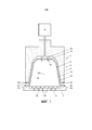
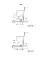
фиг.1 показывает схематическое изображение варианта выполнения системы согласно изобретению;figure 1 shows a schematic illustration of an embodiment of a system according to the invention;
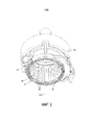
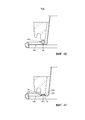
фиг.2 показывает на виде в перспективе вариант выполнения предназначенного для приготовления напитков устройства системы согласно изобретению, при этом показана кольцевая торцевая поверхность охватывающего элемента устройства для приготовления напитков с множеством проходящих в радиальном направлении, открытых канавок;FIG. 2 shows a perspective view of an embodiment of a beverage device of the system according to the invention, wherein an annular end surface of the female element of a beverage device with a plurality of radially extending open grooves is shown;
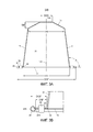
фиг.3А показывает в сечении вариант выполнения капсулы согласно изобретению перед использованием;figa shows in cross section an embodiment of the capsule according to the invention before use;
фиг.3В показывает увеличенный фрагмент капсулы по фиг.3А, показывающий выступающий наружу фланец и уплотнительную конструкцию;FIG. 3B shows an enlarged fragment of the capsule of FIG. 3A, showing an outwardly extending flange and sealing structure;
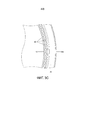
фиг.3С показывает увеличенный фрагмент выступающего наружу фланца капсулы по фиг.3А и 3В после использования;3C shows an enlarged fragment of the protruding outward flange of the capsule of FIGS. 3A and 3B after use;
фиг.4А-4Н показывают несколько вариантов выполнения уплотнительной конструкции на выступающем наружу фланце капсулы согласно изобретению.figa-4H show several embodiments of the sealing structure on the protruding outward flange of the capsule according to the invention.
Фиг.1 показывает схематическое изображение на виде с разрезом варианта выполнения системы 1 для приготовления пригодного для питья напитка из капсулы путем использования текучей среды, подаваемой под давлением в капсулу. Система 1 содержит капсулу 2, которая запечатана для ее герметизации, и устройство 4 для приготовления напитков. Устройство 4 содержит охватывающий элемент 6 для удерживания капсулы 2. Устройство 4 дополнительно содержит закрывающий элемент 8, такой как экстракционная пластина, для обеспечения опоры для капсулы 2.Figure 1 shows a schematic view in sectional view of an embodiment of a
На фиг.1 для ясности изображен зазор между капсулой 2, охватывающим элементом 6 и экстракционной пластиной 8. Следует понимать, что при использовании капсула 2 может находиться в контакте с охватывающим элементом 6 и экстракционным пластинчатым элементом 8. Обычно охватывающий элемент 6 имеет форму, комплементарную по отношению к форме капсулы 2. Устройство 4 дополнительно содержит средство 10 нагнетания текучей среды, предназначенное для подачи некоторого количества текучей среды, такой как вода, под давлением в диапазоне 6-20 бар, предпочтительно, между 12 и 18 бар, в сменную капсулу 2.1, for clarity, shows the gap between the
В примере, показанном на фиг.1, сменная капсула 2 содержит алюминиевый корпус 12 капсулы, имеющий центральную ось 12А корпуса капсулы, и алюминиевую крышку 14. В данном примере алюминиевый корпус 12 капсулы содержит боковую стенку 16, нижнюю часть 18, закрывающую боковую стенку 16 на первом конце, и выступающий наружу фланец 20, выступающий наружу от окружной стенки 16 на втором конце, противоположном нижней части 18. Боковая стенка 16, нижняя часть 18 и крышка 14 охватывают внутреннее пространство 22, содержащее вещество для приготовления пригодного для питья напитка путем экстракции и/или растворения вещества. Вещество предпочтительно представляет собой 5-20 граммов, предпочтительно, 5-10 граммов, более предпочтительно, 5-7 граммов экстрагируемого продукта, такого как обжаренный и молотый кофе, для приготовления одной порции напитка. Капсула исходно запечатана, то есть герметично закрыта перед использованием.In the example shown in FIG. 1, the
Система 1 по фиг.1 содержит средства 24 прокалывания нижней части, предназначенные для прокалывания нижней части 18 капсулы 2 для создания по меньшей мере одного входного отверстия 25 в нижней части 18 для подачи текучей среды в экстрагируемый продукт через входное отверстие 25.The
Система 1 по фиг.1 дополнительно содержит средства 26 прокалывания крышки, выполненные в данном случае в виде выступов закрывающего элемента 8 для прокалывания крышки 14 капсулы 2. Средства 26 прокалывания крышки могут быть выполнены с возможностью разрыва крышки 14, как только давление (текучей среды) во внутреннем пространстве 22 превысит пороговое давление и обеспечит поджим крышки 14 к средствам 26 прокалывания крышки с достаточной силой. Таким образом, алюминиевая крышка 14 выполнена с возможностью разрыва на закрывающем элементе 8 устройства для приготовления напитков под действием давления текучей среды в капсуле.The
Капсула 2 дополнительно содержит уплотнительную конструкцию 28, показанную на фиг.1, 3А и 3В в виде обычной рамки, но описанную более подробно со ссылкой на фиг.4А-4Н, при этом указанная уплотнительная конструкция 28 выполнена на выступающем наружу фланце 20 для обеспечения уплотняющего по отношению к текучей среде контакта с охватывающим элементом 6, если капсула 2 установлена в заданном положении в охватывающем элементе 6 и охватывающий элемент 6 закрыт посредством экстракционной пластины 8, так что выступающий наружу фланец 20 капсулы 2 и по меньшей мере часть уплотнительной конструкции 28 герметично захватываются между охватывающим элементом 6 и экстракционной пластиной 8.The
Как показано на фиг.2, охватывающий элемент 6 устройства для приготовления напитков содержит кольцевой элемент 41, имеющий центральную ось 41А кольцевого элемента и свободную кольцевую торцевую поверхность 30. Кольцевая торцевая поверхность 30 кольцевого элемента 41 выполнена с множеством проходящих в радиальном направлении, открытых канавок 40. Множество проходящих в радиальном направлении, открытых канавок 40 равномерно распределены друг относительно друга в окружном направлении кольцевой торцевой поверхности 30 кольцевого элемента 41. Наибольшая ширина каждой канавки 40 в окружном направлении составляет 0,9-1,1 мм, предпочтительно, 0,95-1,05 мм, более предпочтительно, 0,98-1,02 мм, при этом максимальная высота каждой канавки 40 в аксиальном направлении охватывающего элемента 6 составляет 0,01-0,09 мм, предпочтительно, 0,03-0,07 мм, более предпочтительно, 0,045-0,055 мм и наиболее предпочтительно 0,05 мм. Число канавок 40 находится в диапазоне 90-110, предпочтительно составляет 96. Ширина кольцевой торцевой поверхности в радиальном направлении в месте расположения канавок может составлять, например, 0,05-0,9 мм, предпочтительно, 0,2-0,7 мм и, более предпочтительно, 0,3-0,55 мм.As shown in FIG. 2, the
Вариант выполнения капсулы согласно изобретению показан более подробно на фиг.3А и 3В. В показанном варианте выполнения наружный диаметр ODF выступающего наружу фланца 20 превышает диаметр DB нижней части 18 капсулы 2. В показанном варианте выполнения наружный диаметр ODF выступающего наружу фланца 20 составляет приблизительно 37,1 мм, и диаметр DB нижней части 18 составляет приблизительно 23,3 мм. В представленном примере толщина стенки алюминиевого корпуса 12 капсулы составляет 100 микрон. Как правило, в зависимости от различных соображений предпочтительна толщина стенки, составляющая 20-200 микрон.An embodiment of the capsule according to the invention is shown in more detail in FIGS. 3A and 3B. In the shown embodiment, the outer diameter of the ODF of the outwardly extending
В показанном варианте выполнения толщина алюминиевой крышки 14 составляет 39 микрон, при этом предпочтительная толщина находится в диапазоне 15-65 микрон и более конкретно 30-45 микрон. Толщина алюминиевой крышки 14 предпочтительно меньше толщины алюминиевого корпуса 12 капсулы.In the embodiment shown, the thickness of the
Боковая стенка 16 алюминиевого корпуса 12 капсулы имеет свободный конец 42, противоположный нижней части 18. Внутренний диаметр IDF свободного конца 42 боковой стенки 16 алюминиевого корпуса 12 капсулы составляет приблизительно 29,5 мм. Выступающий наружу фланец 20 выступает от данного свободного конца 42 в направлении по меньшей мере по существу поперечном к центральной оси 12А корпуса капсулы. Выступающий наружу фланец 20 содержит закрученную наружную кромку 43, которая предпочтительна для обеспечения уплотнения между капсулой и охватывающим элементом. В показанном варианте выполнения закрученная наружная кромка 43 выступающего наружу фланца 20 имеет наибольший размер, составляющий приблизительно 1,2 миллиметра. Расстояние DIF между свободным концом 42 боковой стенки 16 алюминиевого корпуса 12 капсулы и внутренним краем 43А закрученной наружной кромки 43 составляет приблизительно 2,7 мм, в то время как расстояние DOF между свободным концом 42 боковой стенки 16 алюминиевого корпуса 12 капсулы и самым дальним от центра краем 43В выступающего наружу фланца 20 составляет приблизительно 3,8 миллиметра.The
Как показано на фиг.3А и 3В, уплотнительная конструкция 28 расположена между свободным концом боковой стенки 16 алюминиевого корпуса 12 капсулы и внутренним краем 43А закрученной наружной кромки 43 выступающего наружу фланца. Уплотнительная конструкция 28 показана в виде обычной рамки, но будет описана более подробно ниже. Независимо от варианта выполнения уплотнительной конструкции 28 высота уплотнительной конструкции предпочтительно составляет по меньшей мере приблизительно 0,1 мм, более предпочтительно, по меньшей мере 0,2 мм и, наиболее предпочтительно, по меньшей мере 0,8 мм и самое большее 3 мм, более предпочтительно, самое большее 2 мм и, наиболее предпочтительно - самое большее 1,2 мм для обеспечения надлежащего уплотнения.As shown in FIGS. 3A and 3B, the sealing
Как можно видеть из фиг.3А, алюминиевый корпус 12 капсулы является усеченным. В показанном варианте выполнения боковая стенка 16 алюминиевого корпуса 12 капсулы образует угол А с линией, поперечной к центральной оси 12А корпуса капсулы, составляющий приблизительно 97,5°. Нижняя часть 18 алюминиевого корпуса 12 капсулы имеет наибольший внутренний диаметр DB, составляющий приблизительно 23,3 мм. Нижняя часть 18 алюминиевого корпуса 12 капсулы также является усеченной и в показанном варианте выполнения имеет высоту ВН нижней части, составляющую приблизительно 4,0 мм. Нижняя часть 18 дополнительно имеет по существу плоскую центральную часть 18А, противоположную крышке 14, при этом указанная центральная часть 18А имеет диаметр DEE, составляющий приблизительно 8,3 мм, и в указанной центральной части 18А может/могут быть образовано (-ы) входное (-ые) отверстие (-я) 25. Входные отверстия также могут быть образованы в усеченной части между центральной частью 18А и боковой стенкой 16. Общая высота ТН алюминиевого корпуса 12 капсулы составляет приблизительно 28,4 мм.As can be seen from FIG. 3A, the
Система 1, показанная на фиг.1 функционирует следующим образом для приготовления чашки пригодного для питья напитка, в представленном примере - кофе, при этом вещество в капсуле представляет собой обжаренный и молотый кофе.The
Капсулу 2 размещают в охватывающем элементе 6. Экстракционную пластину 8 вводят в контакт с капсулой 2. Средства 24 прокалывания нижней части прокалывают нижнюю часть 18 капсулы 2 для образования входных отверстий 25. Текучая среда, в данном случае горячая вода под давлением, подается в экстрагируемый продукт, находящийся во внутреннем пространстве 22, через входные отверстия 25. Вода будет смачивать молотый кофе и экстрагировать желательные вещества для образования кофейного напитка.The
Во время подачи воды под давлением во внутреннее пространство 22 давление внутри капсулы 2 будет повышаться. Повышение давления вызовет деформирование крышки 14 и ее поджим к предназначенным для прокалывания крышки средствам 26 экстракционной пластины. Как только давление достигнет определенного уровня, прочность крышки 14 на разрыв будет преодолена, и крышка 14 разорвется у средств 26 прокалывания крышки, что приведет к образованию выходных отверстий. Приготовленный кофе будет вытекать из капсулы 2 через выходные отверстия и выпускные каналы 32 (см. фиг.1) экстракционной пластины 8 и может быть подан в контейнер, такой как чашка (непоказанная).During the supply of pressurized water to the
Система 1 выполнена таким образом, что перед варкой или в начале варки свободный конец 30 охватывающего элемента 6 обеспечивает приложение силы F1 к уплотнительной конструкции 28 капсулы 2 для обеспечения уплотняющего контакта между выступающим наружу фланцем 20 капсулы 2 и охватывающим элементом 6 устройства для приготовления напитков, при этом сила F1 находится в диапазоне 30-150 Н, предпочтительно, 40-150 Н и более предпочтительно 50-100 Н, когда давление Р1 текучей среды в охватывающем элементе устройства для приготовления напитков снаружи капсулы находится в диапазоне 0,1-4 бар, предпочтительно, 0,1-1 бар. Во время варки свободный конец 30 охватывающего элемента 6 обеспечивает приложение силы F2 к уплотнительной конструкции 28 капсулы 2 для обеспечения уплотняющего контакта между выступающим наружу фланцем 20 капсулы 2 и охватывающим элементом 6, при этом сила F2 находится в диапазоне 500-1500 Н, предпочтительно, в диапазоне 750-1250 Н, когда давление Р2 текучей среды в охватывающем элементе 6 устройства для приготовления напитков снаружи капсулы 2 находится в диапазоне 6-20 бар, предпочтительно, между 12 и 18 бар. В показанном варианте выполнения компонент 6В охватывающего элемента 6 может перемещаться относительно экстракционной пластины 8 под действием давления текучей среды в охватывающем элементе 6 устройства к экстракционной пластине 8 для приложения максимальной силы между выступающим наружу фланцем 20 и свободным концом 30 охватывающего элемента 6. Данное перемещение может происходить во время использования, то есть в начале варки и во время варки. Охватывающий элемент 6 имеет первый компонент 6А и второй компонент 6В, при этом второй компонент содержит кольцевую торцевую поверхность 30. Второй компонент 6В может перемещаться относительно первого компонента 6А между первым и вторым положениями. Второй компонент 6В может перемещаться из первого положения ко второму положению в направлении закрывающего элемента 8 под действием давления текучей среды в охватывающем элементе 6. Сила F1, рассмотренная выше, может быть достигнута, если второй компонент 6В находится в первом положении при давлении Р1 текучей среды. Сила F2, рассмотренная выше, может быть достигнута, если второй компонент 6В перемещен по направлению ко второму положению под действием давления Р2 текучей среды в охватывающем элементе 6.The
В результате приложения силы уплотнительная конструкция 28 капсулы согласно изобретению подвергается пластической деформации и принимает форму, близкую к форме канавок 40 кольцевой торцевой поверхности 30, и, следовательно, обеспечивает уплотняющий контакт между охватывающим элементом 6 и капсулой 2 при сравнительно низком давлении текучей среды во время начала варки, но также обеспечивает уплотняющий контакт при значительно более высоком давлении текучей среды в охватывающем элементе снаружи капсулы во время варки. Данное близкое соответствие по форме канавкам 40 охватывающего элемента показано на фиг.3С, которая показывает капсулу 2 по изобретению после использования, и которая ясно показывает, что выступающий наружу фланец 20 содержит деформированные части 40', которые соответствуют по форме канавкам 40 охватывающего элемента.As a result of the application of force, the sealing
Далее иллюстративные варианты выполнения уплотнительной конструкции 28 на выступающем наружу фланце 20 капсулы 2 согласно изобретению будут описаны более подробно в связи с фиг.4А-4Н.Next, illustrative embodiments of the sealing
На фиг.4А показан первый пример фланца 20 с уплотнительной конструкцией 28, находящейся в контакте с кольцевой торцевой поверхностью охватывающего элемента 6 перед деформированием уплотнительной конструкции 28. Уплотнительная конструкция имеет вид деформируемой уплотнительной кольцевой части 28 фланца 20. Крышка 14 прикреплена к базовым частям 44, 45 фланца 20, которые определяют ровную плоскость плоского основания фланца 20, перпендикулярную к оси корпуса капсулы. Уплотнительная кольцевая часть 28 выступает в аксиальном направлении от базовых частей 44, 45 фланца 20 со стороны базовых частей 44, 45, противоположной по отношению к крышке 14 (то есть, со стороны, обращенной к кольцевой торцевой поверхности 30).4A shows a first example of a
Деформируемая уплотнительная кольцевая часть 28 имеет внутреннюю стеночную часть 46, проходящую от внутренней базовой части 44 и смежную с внутренней базовой частью 44 фланца 20, и наружную стеночную часть 47, проходящую от наружной базовой части 45 и смежную с наружной базовой частью 45 фланца 20. Наружная стеночная часть 47 расположена снаружи и на расстоянии от внутренней стеночной части 46. Деформируемая уплотнительная кольцевая часть 28 дополнительно содержит соединяющую часть 48, соединяющую друг с другом внутреннюю стеночную часть 46 и наружную стеночную часть 47. Соединяющая часть 48 расположена на расстоянии в аксиальном направлении от базовых частей 44, 45 фланца 20. На показанном виде в разрезе верхняя часть 49 соединяющей части, наиболее удаленная в аксиальном направлении от базовых частей 44, 45 фланца, имеет центральную плоскость, изогнутую с радиусом кривизны, превышающим более чем в два раза толщину стенки верхней части 49 соединяющей части 48. Поскольку радиус кривизны является довольно большим, верхняя часть 49 может деформироваться сравнительно легко для адаптации к форме кольцевой торцевой поверхности 30 при поджиме кольцевой торцевой поверхности 30 к деформируемой уплотнительной кольцевой части 28, вызывающем ее деформацию. Поскольку деформируемая уплотнительная кольцевая часть 28 представляет собой неотъемлемую часть корпуса капсулы, она может быть изготовлена эффективно, и, будучи изготовленной из того же материала, что и остальная часть корпуса капсулы, она может быть подвергнута рециклингу вместе с остальной частью корпуса капсулы после использования и выбрасывания капсулы.The deformable
Внутренняя стеночная часть 46 ориентирована под углом относительно базовых частей 44, 45 фланца, отличным от угла наружной стеночной части 47. Это приводит к точному и надежному деформированию уплотнительной конструкции 28 до заданной формы во время уплотнения. В частности, избегают ситуации, при которой переходные зоны между окружными частями, деформирующимися до разных конечных форм, образуются во время деформаций. Подобные переходные зоны приводят к повышенному риску утечки.The
В представленном примере данный эффект достигается особенно действенно, поскольку наружная стеночная часть проходит под непрямым углом относительно плоскости соответствующей смежной базовой части фланца, и внутренняя стеночная часть проходит от соответствующей смежной базовой части фланца под противоположным углом так, что она будет параллельная наружной стеночной части 47. Непрямой угол предпочтительно составляет 20-60° и, более предпочтительно, 30-50°, и противоположный угол предпочтительно составляет 120-160° и, более предпочтительно, 110-150° относительно плоскости соответствующих сопряженных смежных базовых частей 44, 45 фланца.In the presented example, this effect is achieved especially effectively, since the outer wall portion extends at an indirect angle relative to the plane of the corresponding adjacent base portion of the flange, and the inner wall portion extends from the corresponding adjacent base portion of the flange at an opposite angle so that it is parallel to the
В примере, показанном на фиг.4В, наружная стеночная часть 147 приблизительно перпендикулярна к базовой части фланца, смежной с ней. Помимо изогнутой части, включающей в себя верхнюю часть 149, соединяющая часть 148 также имеет наклонную, по существу плоскую часть 150. Для плавного, точного и надежного деформирования до заданной формы внутренняя стеночная часть 146 имеет криволинейную центральную плоскость, кривизна которой близка к кривизне верхней части указанной соединяющей части. Сравнительно легкое сжатие криволинейной внутренней стеночной части 146 обеспечивается посредством «шарнирного» изгибания плоской части 150 соединяющей части вокруг места ее соединения с наружной стеночной частью 147. Таким образом, избегают ситуации, при которой внутренняя стеночная часть 146 и соседняя часть соединяющей части 148 плоско складываются в одну сторону, и гарантируется то, что изогнутые части, образованные данными частями, будут загибаться относительно них самих во время деформирования, в результате чего обеспечивается то, что во время деформирования будет действовать сравнительно постоянная противодействующая сила.In the example shown in FIG. 4B, the
На фиг.4С показан пример, в котором верхняя часть 249 соединяющей части 248 является плоской (то есть имеет бесконечно большой радиус кривизны). Кроме того, такая плоская стеночная часть может деформироваться сравнительно легко для плавной адаптации к форме кольцевой торцевой поверхности 30. Внутренняя и наружная стеночные части 246, 247 ориентированы перпендикулярно к соседним базовым частям 244, 245 фланца, так что обеспечивается особенно жесткая опора для соединяющей части 248, что предотвращает смещение соединяющей части в целом под действием давления, действующего со стороны кольцевой торцевой поверхности 30, так что деформации по меньшей мере вначале концентрируются в самой соединяющей части 248. В свою очередь, это предпочтительно для адаптации формы уплотнительной кольцевой части 228 к форме кольцевой торцевой поверхности 30. Особенно эффективное и надежное уплотнение уже при низком давлении уплотнения может быть обеспечено, если по меньшей мере участок верхней части 249 соединяющей части 248 имеет уменьшенную толщину стенки, которая меньше толщины стенки внутренней и наружной стеночных частей 247, 246 (уменьшенная толщина стенки не показана на фиг.4С). В этом и других вариантах выполнения уменьшенная толщина по меньшей мере верхней части соединяющей части может составлять, например, 10-95 микрон, более предпочтительно, 30-70 микрон, наиболее предпочтительно, 40-50 микрон.FIG. 4C shows an example in which the
В примере, показанном на фиг.4D, деформируемая уплотнительная кольцевая часть является Ω-образной, при этом внутренняя стеночная часть 346, соединяющая часть 348 с верхней частью 349 и наружная стеночная часть 347 имеют по существу постоянный радиус кривизны. Подобная форма является особенно предпочтительной для плавного, точного и надежного деформирования до заданной формы. Другое преимущество такой формы состоит в том, что только небольшой зазор остается между внутренней и наружной базовыми частями 344, 345 фланца, так что остается большая площадь поверхности для прилипания крышки 14 к фланцу.In the example shown in FIG. 4D, the deformable sealing ring portion is Ω-shaped, with the
Кроме того, в примере, показанном на фиг.4D, деформируемая уплотнительная кольцевая часть 428 является Ω-образной, но имеет больший радиус кривизны, так что ширина Ω-образной части по меньшей мере такая же, как ширина кольцевой торцевой поверхности 30. Это обеспечивает возможность вдавливания кольцевой торцевой поверхности в (первоначально) Ω-образную часть, ширина которой увеличивается во время деформирования, так что обеспечивается особенно эффективное двойное уплотнение в наружной и внутренней граничных зонах кольцевой торцевой поверхности 30.In addition, in the example shown in FIG. 4D, the deformable
В примере, показанном на фиг.4F, опорный элемент 551 из сравнительно упругого материала предусмотрен между внутренней и наружной стеночными частями 546, 547 и под соединяющей частью 548 для обеспечения высокого противодавления во время последней стадии деформирования уплотнительной конструкции. Подобный опорный элемент особенно предпочтителен, если, как в представленном примере, деформируемая уплотнительная кольцевая часть 528 имеет сравнительно плоскую конфигурацию.In the example shown in FIG. 4F, a
Особенная хорошая способность к адаптации к форме кольцевой торцевой поверхности 30 и, соответственно, особенно эффективное и надежное уплотнение уже при низком давлении уплотнения могут быть обеспечены, если, как в примере, показанном на фиг.4G по меньшей мере участок верхней части 649 соединяющей части 648 имеет уменьшенную толщину стенки, меньшую, чем толщина стенки внутренней и наружной стеночных частей 647, 646.Particular good adaptability to the shape of the
Соединяющая часть 649 может иметь поверхность без покрытия, обращенную к кольцевой торцевой поверхности 30, в то время как остальная часть материала корпуса капсулы может иметь покрытие на той же стороне или на обеих сторонах, для избежания повреждения покрытия во время уменьшения толщины стенки или при удалении покрытия во время уменьшения толщины стенки. При удалении покрытия текстура может быть создана на поверхности, с которой удалено покрытие. Подобная текстура, предпочтительно включающая гребнеобразные выступы и впадины в направлении вдоль окружности фланца, может дополнительно улучшить прилегаемость во время ранних стадий зажима, когда давление уплотнения еще низкое, поскольку усилие зажима передается только через выступающие части текстуры, так что на выступающих частях будет действовать более высокое контактное давление, чем действовало бы на полностью гладкой поверхности контакта.The connecting
На фиг.4Н показан пример, в котором одна из стеночных частей 746, 747 (в данном случае наружная стеночная часть 747) ориентирована под бóльшим углом относительно базовых частей 744, 745 фланца, чем другая из стеночных частей 746, 747 (в данном случае внутренняя стеночная часть 746), которая ориентирована наклонно относительно базовых частей 744, 745 фланца. Кроме того, в данном примере наклонная стеночная часть 746, которая поворачивается вслед за деформированием соединяющей части 748 и «крутой» стеночной части 747, предотвращает перегибание «крутой» стеночной части 747, которая деформируется в наибольшей степени. «Крутая» наружная стеночная часть 747 расположена так, что она загибается наружу по отношению к кольцевой торцевой поверхности 30 при придавливании охватывающего элемента к верхней части 749 соединяющей части. При этом материал стенки верхнего конца крутой наружной стеночной части 747 деформируется с кренением, когда он следует за соединяющей частью 748, которая вдавливается вниз, и удерживается в радиальном направлении посредством поворачивающейся внутренней стеночной части 746, как проиллюстрировано посредством деформированных состояний 728' и 728ʺ деформируемой уплотнительной части 728, показанных на фиг.4Н. Таким образом, сначала обеспечивается локальная деформация для адаптации к форме кольцевой торцевой поверхности 30, когда кольцевая торцевая поверхность 30 поджимается к верхней части 749 соединяющей части 748. Впоследствии деформация, подобная кренению, обеспечивает возможность плавного аксиального деформирования на большой траектории.Fig. 4H shows an example in which one of the
В каждом из примеров, показанных на фиг.4А-4Н, верхняя часть соединяющей части расположена так, что кольцевая торцевая часть 30 сначала входит в контакт с данной верхней частью, когда уплотнительная кольцевая часть зажимается между кольцевой торцевой поверхностью и закрывающим элементом совместимого устройства для приготовления напитков. Кроме того, диаметр верхней части соединяющей части является таким, что верхняя часть соединяющей части будет расположена центрально относительно кольцевой торцевой поверхности 30 для контактирования сначала с центральной частью данной кольцевой торцевой поверхности, когда уплотнительная кольцевая часть зажимается между кольцевой торцевой поверхностью и указанным закрывающим элементом совместимого устройства для приготовления напитков.In each of the examples shown in figa-4H, the upper part of the connecting part is located so that the
В вышеприведенном описании изобретение было описано со ссылкой на конкретные примеры вариантов выполнения изобретения. Тем не менее, будет очевидно, что различные модификации и изменения могут быть выполнены в них без отхода от более широкой сущности и объема изобретения, определяемых приложенной формулой изобретения.In the above description, the invention has been described with reference to specific examples of embodiments of the invention. However, it will be apparent that various modifications and changes can be made therein without departing from the broader nature and scope of the invention as defined by the appended claims.
Claims (41)
Applications Claiming Priority (3)
| Application Number | Priority Date | Filing Date | Title |
|---|---|---|---|
| NLPCT/NL2015/050351 | 2015-05-15 | ||
| NL2015050351 | 2015-05-15 | ||
| PCT/NL2016/050341 WO2016186488A1 (en) | 2015-05-15 | 2016-05-13 | A capsule, a system for preparing a potable beverage from such a capsule and use of such a capsule in a beverage preparation device |
Publications (3)
| Publication Number | Publication Date |
|---|---|
| RU2017143834A RU2017143834A (en) | 2019-06-17 |
| RU2017143834A3 RU2017143834A3 (en) | 2019-07-17 |
| RU2710768C2 true RU2710768C2 (en) | 2020-01-13 |
Family
ID=53487397
Family Applications (1)
| Application Number | Title | Priority Date | Filing Date |
|---|---|---|---|
| RU2017143834A RU2710768C2 (en) | 2015-05-15 | 2016-05-13 | Capsule, system for preparing drink suitable for drinking from similar capsule and use of such capsule in beverage preparation device |
Country Status (24)
| Country | Link |
|---|---|
| US (2) | US11760561B2 (en) |
| EP (2) | EP3594149A1 (en) |
| JP (2) | JP6779236B2 (en) |
| KR (1) | KR102602908B1 (en) |
| CN (2) | CN107835774B (en) |
| AT (2) | AT517143A2 (en) |
| AU (3) | AU2016264683B2 (en) |
| BE (1) | BE1023445B1 (en) |
| BR (1) | BR112017024464B1 (en) |
| CA (1) | CA2985973C (en) |
| CH (1) | CH711080B1 (en) |
| DE (2) | DE102016006030A1 (en) |
| DK (3) | DK3134329T3 (en) |
| ES (1) | ES2743219T3 (en) |
| FR (1) | FR3036106B3 (en) |
| GB (1) | GB2538399A (en) |
| IL (1) | IL255673B (en) |
| IT (1) | ITUA20163464A1 (en) |
| MX (1) | MX2017014642A (en) |
| NL (1) | NL2016777B1 (en) |
| PL (1) | PL3134329T3 (en) |
| PT (1) | PT3134329T (en) |
| RU (1) | RU2710768C2 (en) |
| WO (1) | WO2016186488A1 (en) |
Families Citing this family (39)
| Publication number | Priority date | Publication date | Assignee | Title |
|---|---|---|---|---|
| US10722066B2 (en) * | 2010-12-04 | 2020-07-28 | Adrian Rivera | Windowed single serving brewing material holder |
| US11832755B2 (en) * | 2007-07-13 | 2023-12-05 | Adrian Rivera | Brewing material container for a beverage brewer |
| RS60188B1 (en) * | 2010-07-22 | 2020-06-30 | K Fee System Gmbh | Portion capsule with barcode |
| CH711080B1 (en) | 2015-05-15 | 2017-08-15 | Douwe Egberts Bv | Capsule, system for preparing a beverage from such a capsule and use of such a capsule in a beverage preparation device. |
| BR112017024468B1 (en) | 2015-05-15 | 2022-02-15 | Koninklijke Douwe Egberts B.V. | CAPSULE, SYSTEM FOR PREPARING A DRINKING BEVERAGE, USE OF A CAPSULE, AND METHOD FOR MANUFACTURING A CAPSULE |
| CA2985977C (en) | 2015-05-15 | 2023-08-29 | Koninklijke Douwe Egberts B.V. | A capsule, a system for preparing a potable beverage from such a capsule and use of such a capsule in a beverage preparation device |
| NL2016776B1 (en) | 2015-05-15 | 2017-01-31 | Douwe Egberts Bv | A capsule, a system for preparing a potable beverage from such a capsule and use of such a capsule in a beverage preparation device |
| DK3134331T3 (en) | 2015-05-15 | 2018-10-22 | Douwe Egberts Bv | COVER, SYSTEM FOR PREPARING A DRINKABLE BEVERAGE FROM SUCH A COVER AND USING SUCH A COVER IN A BEVERAGE COOKING DEVICE |
| NL2016781B1 (en) | 2015-05-15 | 2016-12-30 | Douwe Egberts Bv | A capsule, a system for preparing a potable beverage from such a capsule and use of such a capsule in a beverage preparation device |
| PT3368447T (en) | 2015-10-27 | 2020-05-07 | Douwe Egberts Bv | Capsule, system and method for preparing a beverage |
| NL2016780B1 (en) | 2016-05-13 | 2017-11-16 | Douwe Egberts Bv | A capsule, a system for preparing a potable beverage from such a capsule and use of such a capsule in a beverage preparation device |
| NL2016779B1 (en) | 2016-05-13 | 2017-11-16 | Douwe Egberts Bv | A capsule and a system for preparing a potable beverage from such a capsule |
| NL2019254B9 (en) | 2016-10-07 | 2018-09-10 | Douwe Egberts Bv | A capsule, a system for preparing a potable beverage from such a capsule and use of such a capsule in a beverage preparation device |
| EP3562570A4 (en) * | 2016-11-26 | 2020-12-16 | George Stantchev | Portable extraction device |
| NL2019253B1 (en) | 2017-07-14 | 2019-01-28 | Douwe Egberts Bv | Assembly of a capsule and a brew chamber, brew chamber, beverage preparation machine, capsule and use of a capsule. |
| EP3434159A1 (en) * | 2017-07-28 | 2019-01-30 | Anthony Kay | Sealing system for beverage capsules and beverage extraction system |
| GB201720894D0 (en) * | 2017-11-08 | 2018-01-31 | Gort-Barten Alex | Beverage capsule |
| WO2019149875A2 (en) * | 2018-02-01 | 2019-08-08 | K-Fee System Gmbh | Portion capsule for preparing a beverage in a beverage preparation machine, method for producing a portion capsule, machine for producing a portion capsule, and method for producing a beverage using a beverage preparation machine and portion capsule |
| HRP20220821T1 (en) * | 2018-04-11 | 2022-10-14 | Goglio S.P.A. | Capsule for preparing beverages, particularly coffee |
| TW202023919A (en) * | 2018-09-14 | 2020-07-01 | 瑞士商雀巢製品股份有限公司 | Capsule for beverage preparation with integrally formed sealing member |
| EP3883865B1 (en) * | 2018-11-22 | 2022-11-09 | GCS German Capsule Solution GmbH | Seal of a portion capsule |
| AU2019392611A1 (en) * | 2018-12-04 | 2021-05-27 | Société des Produits Nestlé S.A. | A beverage pod |
| NL2022265B1 (en) * | 2018-12-20 | 2020-07-15 | Douwe Egberts Bv | System for preparing a beverage from a capsule using a fluid supplied under pressure into the capsule and a capsule for use in such a system |
| CN113439062B (en) | 2019-02-13 | 2023-06-02 | Gcs德国胶囊解决方案股份有限公司 | Portion capsule for preparing a beverage in a beverage preparation machine and system for preparing a beverage from said portion capsule |
| EP3702298A1 (en) * | 2019-03-01 | 2020-09-02 | Delica AG | Capsule and system for for preparing a liquid food |
| IT201900006046A1 (en) * | 2019-04-18 | 2020-10-18 | Aroma System S R L | CAPSULE WITH SEAL |
| GB2584610B (en) * | 2019-05-07 | 2023-02-15 | Alexander Charles Gort Barten | Beverage capsule |
| US20230052831A1 (en) * | 2020-02-19 | 2023-02-16 | Sarong Societa'per Azioni | Capsule for beverages |
| IT202000007669A1 (en) * | 2020-04-09 | 2021-10-09 | Sarong Spa | Beverage capsule |
| CA3168619A1 (en) | 2020-02-19 | 2021-08-26 | Sarong Societa' Per Azioni | Capsule for beverages |
| US11805934B1 (en) * | 2020-10-21 | 2023-11-07 | Adrian Rivera | Brewing material lid and container for a beverage brewer |
| US20240101340A1 (en) | 2020-12-07 | 2024-03-28 | Gcs German Capsule Solution Gmbh | Single Serve Capsule For Preparing A Beverage In A Beverage Preparation Machine, And Method For Producing A Single Serve Capsule |
| CN113509051A (en) * | 2021-07-16 | 2021-10-19 | 云南五季生物科技有限公司 | Shell-packed beverage and brewing machine |
| CA3226645A1 (en) | 2021-07-30 | 2023-02-02 | Marc Kruger | Single serve capsule for preparing a beverage with the aid of a beverage preparation machine, and use of a single serve capsule |
| AU2022318260A1 (en) | 2021-07-30 | 2024-02-08 | K-Fee System Gmbh | Single serve capsule for preparing a beverage with the aid of a beverage preparation machine, and use of a single serve capsule |
| CA3226649A1 (en) | 2021-07-30 | 2023-02-02 | Marc Krueger | Single serve capsule for preparing a beverage with the aid of a beverage preparation machine, and use of a single serve capsule |
| WO2023007024A1 (en) | 2021-07-30 | 2023-02-02 | K-Fee System Gmbh | Single serve capsule for preparing a beverage with the aid of a beverage preparation machine, and use of a single serve capsule |
| WO2023147987A1 (en) | 2022-02-07 | 2023-08-10 | K-Fee System Gmbh | Single-serve capsule for preparing a beverage with the aid of a beverage preparation machine, and use of a single-serve capsule |
| WO2023151902A1 (en) | 2022-02-11 | 2023-08-17 | K-Fee System Gmbh | Single-serve capsule for preparing a beverage using a beverage-preparation machine, beverage-preparation system, and method for producing a single-serve capsule |
Citations (3)
| Publication number | Priority date | Publication date | Assignee | Title |
|---|---|---|---|---|
| WO2014012779A2 (en) * | 2012-07-16 | 2014-01-23 | Tuttoespresso S.R.L. | Capsule with improved sealing element |
| WO2014184653A1 (en) * | 2013-05-17 | 2014-11-20 | Kraft Foods R&D, Inc. | A beverage preparation system, a capsule and a method for forming a beverage |
| WO2014184652A1 (en) * | 2013-05-17 | 2014-11-20 | Kraft Foods R&D, Inc. | A beverage preparation system, a capsule and a method for forming a beverage |
Family Cites Families (179)
| Publication number | Priority date | Publication date | Assignee | Title |
|---|---|---|---|---|
| CA1077001A (en) | 1976-10-21 | 1980-05-06 | Winfried J. Werding | Appliance for discharging gaseous liquid or pasty product, and process of its manufacture |
| JPS5926460A (en) | 1982-08-06 | 1984-02-10 | 東洋製罐株式会社 | Composite material for packing vessel cover |
| US4651538A (en) | 1985-09-06 | 1987-03-24 | Schneider Metal Manufacturing Co. | Beverage cooler having a cold plate and plastic ice bin |
| US4913951A (en) | 1988-07-26 | 1990-04-03 | Garlock Inc. | Fabrication of reinforced PTFE gasketing material |
| DK0468079T3 (en) | 1990-07-27 | 1997-03-03 | Nestle Sa | |
| US5897899A (en) | 1991-05-08 | 1999-04-27 | Nestec S.A. | Cartridges containing substances for beverage preparation |
| US5798599A (en) | 1996-10-24 | 1998-08-25 | Dukane Corporation | Ultrasonic transducer assembly using crush foils |
| DE69616346T2 (en) | 1996-11-22 | 2002-04-18 | Nestle Sa | Closed container containing a powdery substance |
| ATE223336T1 (en) | 1998-12-16 | 2002-09-15 | Alcan Tech & Man Ag | LID FOR CLOSING CONTAINERS |
| JP2000262405A (en) | 1999-03-18 | 2000-09-26 | Soc Prod Nestle Sa | Sealed cartridge for drink extraction |
| US20110027547A1 (en) | 2000-05-02 | 2011-02-03 | Reactive Nanotechnologies, Inc. | Methods of making reactive composite materials and resulting products |
| TWI236360B (en) | 2000-06-30 | 2005-07-21 | Nestle Sa | Capsule cage |
| ES2216791T3 (en) | 2000-09-26 | 2004-11-01 | Societe Des Produits Nestle S.A. | CLOSED CARTRIDGE FOR THE CONFECTION OF A DRINK, INTENDED TO STAY BY PRESSURE. |
| EP1203554A1 (en) | 2000-11-03 | 2002-05-08 | Societe Des Produits Nestle S.A. | Device for extracting food material stored in a reloading cartridge |
| US6550157B1 (en) | 2001-11-09 | 2003-04-22 | Robert W. Harding | Recessed dryer vent system |
| US7118800B2 (en) | 2001-11-21 | 2006-10-10 | Kyodo Printing Co., Ltd. | Laminates and packaging containers |
| EP1495702A1 (en) | 2003-07-10 | 2005-01-12 | Nestec S.A. | Device for the extraction of a cartridge |
| US7758936B2 (en) | 2003-09-18 | 2010-07-20 | Boehringer Ingelheim Gmbh | Pharmaceutical blister |
| US7237698B2 (en) | 2004-01-20 | 2007-07-03 | Brian Francis Jackman | Pressure activated self opening container and seal |
| EP1804874A2 (en) * | 2004-10-12 | 2007-07-11 | Airsep Corporation | Oxygen concentrator with variable temperature and pressure sensing control means |
| JP4865720B2 (en) | 2004-10-25 | 2012-02-01 | ネステク ソシエテ アノニム | Capsule having biasing sealing member |
| DK1654966T3 (en) * | 2004-10-25 | 2007-02-19 | Nestec Sa | Capsule with sealants |
| US8403951B2 (en) | 2005-03-08 | 2013-03-26 | Novartis Ag | Phacoemulsification tip |
| US7506779B2 (en) * | 2005-07-01 | 2009-03-24 | Ball Corporation | Method and apparatus for forming a reinforcing bead in a container end closure |
| EP1839543B1 (en) | 2006-03-31 | 2008-06-25 | Nestec S.A. | Capsule with outer sealing material pressurized by a fluid |
| DE102006015055B4 (en) | 2006-03-31 | 2007-12-27 | Nokia Siemens Networks Gmbh & Co.Kg | Method, arrangement and device for transmitting information between a central and at least one decentralized unit in a communication network |
| DE602006007548D1 (en) * | 2006-04-24 | 2009-08-13 | Nestec Sa | Capsule for beverage preparation with sealing element and method for its production |
| BRPI0710900B1 (en) | 2006-04-24 | 2018-06-19 | Nestec S.A. | CAPSULE FOR PREPARATION OF A DRINK WITH A WATERPROOF WATER-SEALING SEALING AND SAME PRODUCTION METHOD |
| PL2238880T3 (en) | 2006-05-24 | 2012-07-31 | Nestec Sa | Capsule piercing module |
| DK1859714T3 (en) | 2006-05-24 | 2009-05-25 | Nestec Sa | Brewing device and brewing system with a capsule holder for easy insertion and removal of capsules |
| PL2029457T3 (en) | 2006-05-29 | 2010-10-29 | Nestec Sa | Coffee capsule with a deformable sealing element |
| AR061426A1 (en) | 2006-06-01 | 2008-08-27 | Advanced Plastics Technologies | APPARATUS AND METHOD FOR MOLDING THROUGH A GLASS AND CONTAINER FOR STORAGE DRINKS |
| ES2345781T3 (en) | 2006-07-24 | 2010-10-01 | Nestec S.A. | PROCEDURE FOR OBTAINING A SHORT COFFEE EXTRACT WITH GREATER RAPIDITY FROM A CAPSULE. |
| DE602006013966D1 (en) | 2006-07-24 | 2010-06-10 | Nestec Sa | Method for dispensing long coffee from a capsule with reduced flow time |
| DE202006013189U1 (en) | 2006-08-25 | 2006-10-26 | Tchibo Gmbh | Hot beverage e.g. meal coffee, making system, has jacket base with silicon plate having hole which is sealed depending on material properties of plate, before lower mandrel is pulled out from plate |
| ITTO20060661A1 (en) | 2006-09-18 | 2008-03-19 | Nicoletta Francovicchio | SEALED CAPSULA FOR THE PRODUCTION OF A BEVERAGE |
| BRPI0717258B1 (en) | 2006-09-26 | 2019-04-16 | Nestec S.A. | EXTRACTION SYSTEM FOR PREPARING A DRINK FROM A CARTRIDGE |
| DK1967099T3 (en) | 2007-03-06 | 2010-03-15 | Nestec Sa | Device for preparing a nutrient liquid from a capsule |
| DE602008005878D1 (en) | 2007-06-05 | 2011-05-12 | Nestec Sa | CAPSULE SYSTEM, DEVICE AND METHOD FOR PRODUCING A LIQUID FOOD IN A CONTAINER BY CENTRIFUGATION |
| AU2008306060C1 (en) | 2007-10-04 | 2015-08-27 | Société des Produits Nestlé S.A. | Beverage brewing unit |
| DE102007060150B4 (en) | 2007-12-13 | 2010-01-21 | Inde Plastik Betriebsgesellschaft Mbh | Closed sachet with sealing ring and packaging for the production thereof |
| CN102036589A (en) * | 2008-01-15 | 2011-04-27 | 雀巢产品技术援助有限公司 | Sealing adapter for a beverage extraction system suitable for preparing a beverage from cartridges |
| EP2240387A1 (en) | 2008-02-05 | 2010-10-20 | 3A Technology & Management AG | Cover and method for the production thereof |
| WO2009111459A2 (en) * | 2008-03-03 | 2009-09-11 | Smith & Nephew, Inc. | System and method for performing a modular revision hip prosthesis |
| ES2365642T3 (en) * | 2008-03-12 | 2011-10-07 | Nestec S.A. | CAPSULE WITH FLOW CONTROL AND FILTER ELEMENT. |
| DE102008014758A1 (en) * | 2008-03-18 | 2009-10-08 | Inde Plastik Betriebsgesellschaft Mbh | Closed portion package for soluble coffee substance for espresso machine, has side wall provided with carrier section, and inner section, which is formed of flexible plastic foil deformable under pressure and laminated on carrier section |
| CN101977538B (en) | 2008-03-20 | 2013-07-24 | 雀巢产品技术援助有限公司 | Beverage production device for producing a beverage from a single-use capsule |
| EP2291316B1 (en) | 2008-04-14 | 2016-02-24 | Ethical Coffee Company SA | Capsule for beverage preparation |
| ATE529248T1 (en) | 2008-07-15 | 2011-11-15 | Nestec Sa | METHOD FOR APPLYING A LIQUID RUBBER SEAL TO A CAPSULE |
| EP2165937A1 (en) | 2008-09-23 | 2010-03-24 | Nestec S.A. | Bicoloured aluminium container and process for producing said container |
| FR2938417B1 (en) | 2008-11-17 | 2013-07-12 | Tirouvady Moutty | CAPSULE FOR PERCOLATING AROMATIC PRODUCT SUCH AS COFFEE |
| CN102272017B (en) * | 2009-01-05 | 2014-03-26 | 雀巢产品技术援助有限公司 | Capsule with flow control and filtering member |
| US8205415B2 (en) | 2009-01-16 | 2012-06-26 | Kraft Foods Global Brands Llc | Method of packaging and shipping roast and ground coffee |
| JP2012515601A (en) | 2009-01-23 | 2012-07-12 | エシカル コーヒー カンパニー ソシエテ アノニム | Capsules for preparing beverages |
| EP2364930B1 (en) | 2009-03-19 | 2018-12-05 | Nestec S.A. | Capsule for preparing coffee in a device comprising a cartridge holder with relief and recessed elements |
| EP2230195B1 (en) | 2009-03-19 | 2018-04-25 | Nestec S.A. | Capsule with filtering insert for preparing a coffee beverage |
| WO2010116284A2 (en) | 2009-04-08 | 2010-10-14 | Ethical Coffee Company Sa | Brewing device and capsule for preparing a drink |
| IT1393936B1 (en) | 2009-04-09 | 2012-05-17 | I T A Ca S R L Ora Mitaca S R L | CARTRIDGE FOR COFFEE AND SOLUBLE PRODUCTS FOR THE PREPARATION OF DRINKS |
| JP5558565B2 (en) | 2009-06-17 | 2014-07-23 | コーニンクラケ ダウ エグバート ビー.ブイ. | System, method and capsule for preparing a beverage |
| PT2630899T (en) | 2009-06-17 | 2019-08-22 | Douwe Egberts Bv | Capsule, system and method for preparing a predetermined quantity of beverage suitable for consumption |
| SI2510843T1 (en) | 2009-06-17 | 2014-04-30 | Koninklijke Douwe Egberts B.V. | System, capsule and method for preparing a beverage |
| AT508144B1 (en) | 2009-06-30 | 2010-11-15 | Teich Ag | PROCESS FOR PRODUCING PACKAGED PLATINES |
| DE202009009125U1 (en) | 2009-07-02 | 2010-09-09 | Nestec S.A. | Kit for improving the sealing properties of a fillable capsule |
| ES2418329T3 (en) | 2009-07-24 | 2013-08-13 | Ethical Coffee Company Sa | Device for preparing a beverage extracted from a capsule |
| DE202009018042U1 (en) | 2009-08-05 | 2010-12-02 | Nestec S.A. | Capsule with a relief-like sealing element |
| ATE512099T1 (en) | 2009-08-05 | 2011-06-15 | Nestec Sa | CAPSULE WITH ASSOCIATED SEALANTS |
| ES2535755T3 (en) * | 2009-08-19 | 2015-05-14 | Nestec S.A. | Capsule for the preparation of a coffee extract provided with a structure that facilitates water injection drilling |
| US20110185911A1 (en) * | 2009-10-21 | 2011-08-04 | Gino Rapparini | Filtering permeable thermoformed container for beverage-making products with a flat rim |
| US8557314B2 (en) | 2009-11-19 | 2013-10-15 | Nestec S.A. | Capsule and method for preparing a beverage such as coffee from said capsule |
| ES2388892T3 (en) | 2009-12-18 | 2012-10-19 | Delica Ag | Device for preparing a drink and capsule |
| AU2011209447B2 (en) | 2010-01-29 | 2015-08-20 | Société des Produits Nestlé S.A. | Capsule and system for preparing a beverage by centrifugation in a beverage production device |
| RU2555958C2 (en) | 2010-03-19 | 2015-07-10 | Нестек С.А. | Apparatus for beverages preparation with usage of capsules containing ingredients |
| EP2374383B2 (en) | 2010-04-07 | 2019-11-06 | Société des Produits Nestlé S.A. | Extraction system for the production of a beverage using a capsule |
| RU2013101524A (en) | 2010-06-18 | 2014-07-27 | Бисеркон Холдингз Лтд. | CAPSULE, DEVICE AND METHOD FOR PREPARING A DRINK BY EXTRACTION |
| RU2013103514A (en) | 2010-06-28 | 2014-08-10 | Нестек С.А. | CAPSULE DEFINITION SYSTEM |
| DE102010027484A1 (en) | 2010-07-16 | 2012-01-19 | Krüger Gmbh & Co. Kg | Portion capsule i.e. coffee portion capsule, for manufacturing e.g. espresso, has base element comprising edge with fastening plane, membrane attached at plane, and sealing provided on and/or before fastening plane of edge |
| PT2592977T (en) | 2010-07-16 | 2022-03-14 | Nestle Sa | Device for preparing a beverage by centrifugation |
| FR2962893A1 (en) | 2010-07-21 | 2012-01-27 | Capsa Sa | HERMETIC CAPSULE FOR PRESSURIZED EXTRACT DRINK |
| EP2412646A1 (en) | 2010-07-28 | 2012-02-01 | Nestec S.A. | A capsule for food preparation |
| DE102010034260A1 (en) | 2010-08-13 | 2012-02-16 | Valeo Schalter Und Sensoren Gmbh | Sensor holder for fixing sensor, particularly ultrasonic sensors, to cover part of vehicle, has fixing section and retaining section, where retaining section has inlet opening for introducing sensor |
| DE102010047890B4 (en) | 2010-08-16 | 2019-05-29 | K-Fee System Gmbh | Portion capsule with a filter fabric |
| DE102011012881A1 (en) | 2010-09-22 | 2012-03-22 | Krüger Gmbh & Co. Kg | Portion capsule and method of making a beverage with a portion capsule |
| ES2553764T3 (en) | 2010-10-08 | 2015-12-11 | Qbo Coffee Gmbh | Extraction apparatus and sealing system |
| CN103228188B (en) | 2010-11-30 | 2016-04-20 | 雀巢产品技术援助有限公司 | For preparing the capsule of beverage in beverage production device |
| AU2011357283B2 (en) | 2011-01-28 | 2017-02-23 | Société des Produits Nestlé S.A. | Beverage production system and capsule with force ring |
| CN103380066A (en) | 2011-02-16 | 2013-10-30 | 雀巢产品技术援助有限公司 | Container for the preparation of beverage comprising an improved perforable foil and method for preparing a beverage |
| IT1403855B1 (en) | 2011-02-17 | 2013-11-08 | E T I S R L | CAP FOR CONTAINMENT OF A PREPARATION FOR HOT DRINK |
| AU2011361036B2 (en) | 2011-03-03 | 2017-01-19 | Advanced Technology Assets B.V. | Capsule, device and method for preparing a beverage by extraction |
| CA2829071A1 (en) | 2011-03-03 | 2012-10-26 | Biserkon Holdings Ltd. | Capsule, device and method for preparing a beverage by extraction |
| PT2683626T (en) * | 2011-03-07 | 2018-04-04 | Ethical Coffee Company Sa | Capsule for preparing a beverage |
| GB2488799A (en) | 2011-03-08 | 2012-09-12 | Kraft Foods R & D Inc | Drinks Pod without Piercing of Outer Shell |
| WO2012123857A1 (en) | 2011-03-11 | 2012-09-20 | Ethical Coffee Company Sa | Capsule holder for a capsule for preparing a beverage |
| US20120244384A1 (en) | 2011-03-22 | 2012-09-27 | Ball Corporation | Stress Corrosion Resistant Aluminum Beverage End Closure |
| WO2012133897A1 (en) | 2011-03-31 | 2012-10-04 | 旭硝子株式会社 | Vacuum degassig apparatus, apparatus for producing glassware, and method for producing glassware |
| FR2973209B1 (en) | 2011-04-01 | 2014-07-04 | Ahbla Ganibardi | CAPSULE OF BEVERAGE PRODUCT |
| WO2013043048A1 (en) | 2011-09-20 | 2013-03-28 | Koninklijke Douwe Egberts B.V. | Beverage filter systems and methods |
| ITBS20110129A1 (en) | 2011-09-26 | 2013-03-27 | Capitani Srl | CAPSULE FOR THE PRODUCTION OF AN INFUSED DRINK |
| US20140234494A1 (en) | 2011-09-28 | 2014-08-21 | Tuttoespresso S.R.L. | Beverage capsule with sealing element |
| ITMI20111847A1 (en) | 2011-10-10 | 2013-04-11 | Goglio Spa | CARTRIDGE FOR COFFEE AND SOLUBLE PRODUCTS IN GENERAL |
| US20140305315A1 (en) | 2011-10-24 | 2014-10-16 | Nestec S.A. | Capsule for the preparation of a beverage by centrifugation with a sealing flange |
| ES1075815Y (en) | 2011-10-25 | 2012-03-08 | Inventos Para Sist S Vending S L | MONODOSIS CAPSULE FOR ESPRESSO COFFEE MACHINES |
| WO2013068242A1 (en) | 2011-11-07 | 2013-05-16 | Nestec S.A. | Capsule for preparing a beverage with enhanced sealing means |
| EP2780866B1 (en) | 2011-11-15 | 2021-08-11 | Société des Produits Nestlé S.A. | Support and capsule for preparing a beverage by centrifugation, system and method for preparing a beverage by centrifugation |
| WO2013079811A1 (en) | 2011-11-30 | 2013-06-06 | Alain Frydman | Capsule with improved guidance for preparing beverages by extraction |
| US8986763B2 (en) | 2012-02-27 | 2015-03-24 | Rialto Coffee Company Ltd. | Optimal extraction rate coffee capsule with effective seal for diverse group heads |
| US20130224340A1 (en) | 2012-02-27 | 2013-08-29 | Hanan BenDavid | Optimal extraction rate coffee capsule with effective seal for diverse group heads |
| ITBO20120103A1 (en) | 2012-03-05 | 2013-09-06 | Macchiavelli Srl | CAPS FOR INFUSION PRODUCTS |
| RU2014140755A (en) | 2012-03-09 | 2016-04-27 | Конинклейке Филипс Н.В. | ELECTRIC APPLIANCE WHICH IS SUITABLE FOR USE FOR PREPARING A DRINK AT LEAST TWO DIFFERENT WAYS |
| ITVR20120043A1 (en) | 2012-03-14 | 2013-09-15 | Coffee Star S A | DRINK PRODUCTION SYSTEM |
| ES2385235B1 (en) | 2012-03-15 | 2013-05-30 | Javier Lastra Ruiz | Instant Hot Drink Capsule |
| ITBO20120141A1 (en) | 2012-03-16 | 2013-09-17 | Aroma System Srl | CAPSULE TO GET DRINKS EXPRESS TYPE AND METHOD OF OBTAINING ESPRESSO DRINKS |
| ES2675313T3 (en) | 2012-03-26 | 2018-07-10 | Sarong Societa' Per Azioni | Beverage capsule and methods for manufacturing said capsule |
| FR2989258B1 (en) | 2012-04-12 | 2014-07-11 | Tirouvady Moutty | REINFORCED CAPSULE FOR PERCOLATING A PRODUCT SUCH AS COFFEE |
| WO2013157924A1 (en) | 2012-04-17 | 2013-10-24 | Biserkon Holdings Ltd. | Capsule and device for preparing beverages and method for manufacturing a capsule |
| US9876863B2 (en) | 2012-04-20 | 2018-01-23 | Telefonaktiebolaget Lm Ericsson (Publ) | Method, device, network entity and computer program product for providing an IP service application |
| WO2013164669A1 (en) | 2012-05-02 | 2013-11-07 | Russon Holdings Limited | Capsule for use in coffee extraction machines |
| DE102012105282A1 (en) | 2012-06-18 | 2013-12-19 | K-Fee System Gmbh | Portion capsule and method of making a beverage with a portion capsule |
| AU2015255218B2 (en) | 2012-06-18 | 2017-05-25 | K-Fee System Gmbh | Portion capsule and method for producing a beverage by means of a portion capsule |
| WO2013190426A1 (en) | 2012-06-19 | 2013-12-27 | Rialto Coffee Company Ltd. | Optimal extraction rate coffee capsule with effective seal for diverse group heads |
| ES1077395Y (en) | 2012-06-26 | 2012-10-15 | Solubles S A Prod | Capsule to prepare infusions |
| GB2503697B (en) | 2012-07-04 | 2014-12-10 | Alex Gort-Barten | Coffee Capsule |
| EP2682028B1 (en) | 2012-07-04 | 2019-03-13 | Piero Kobler | Insert for a portioning coffee machine |
| JP2015528695A (en) | 2012-07-04 | 2015-10-01 | ネステク ソシエテ アノニム | Method for filling beverage powder in beverage capsules |
| DK2872421T3 (en) | 2012-07-16 | 2017-07-10 | Tuttoespresso Srl | ADJUSTABLE SUSPENSION SYSTEM |
| LU92050B1 (en) | 2012-07-23 | 2014-01-24 | Brain Corp S A | Capsule for the preparation of a drink such as a coffee capsule. |
| ES2473740B1 (en) | 2012-09-03 | 2015-06-02 | Quick Expresso Cap System, S.L. | CAPSULE FOR COFFEE MACHINES. |
| CH707035A2 (en) | 2012-09-26 | 2014-03-31 | Alice Allison Sa | Sachet for espresso machines. |
| ES2593460T3 (en) | 2012-10-05 | 2016-12-09 | Nestec S.A. | Drink capsule with splash prevention medium |
| CN104884368A (en) | 2012-10-29 | 2015-09-02 | Cstec有限公司 | Capsule for holding a brewing material, such as coffee, tea and similar substances, and method for sealing such a capsule |
| US20150298897A1 (en) | 2012-11-09 | 2015-10-22 | Bean Technologies Limited | Capsule for use in coffee extraction machines |
| US10092130B2 (en) | 2012-11-12 | 2018-10-09 | Nestec S.A. | Opener for making large openings in capsules |
| CH707516A2 (en) | 2013-01-17 | 2014-07-31 | Alice Allison Sa | Capsule part for a coffee capsule coffee capsule. |
| ITTO20130067A1 (en) | 2013-01-29 | 2014-07-30 | Bisio Progetti Spa | CAPSULE FOR THE PREPARATION OF BEVERAGES WITH INFUSION. |
| US20160000255A1 (en) | 2013-02-13 | 2016-01-07 | Ethical Coffee Company Sa | Basket for drinks-preparing machine |
| ES1078818Y (en) | 2013-02-22 | 2013-06-10 | Solubles S A Prod | Capsule to prepare infusions |
| CN105431360A (en) | 2013-04-10 | 2016-03-23 | 图托埃布莱束有限公司 | Capsule and system for preparing beverages |
| GB201308927D0 (en) * | 2013-05-17 | 2013-07-03 | Kraft Foods R & D Inc | A beverage preparation system, a capsule and a method for forming a beverage |
| CN105246798B (en) | 2013-05-29 | 2018-12-21 | K-Fee系统股份有限公司 | One cup formula capsule with liquid distribution trough |
| ITMI20130975A1 (en) * | 2013-06-13 | 2014-12-14 | Goglio Spa | CARTRIDGE FOR SOLUBLE PRODUCTS WITH SEALING ELEMENT |
| AU2013392999B2 (en) | 2013-06-17 | 2018-01-18 | Delica Ag | Capsule having a capsule body and method for producing said capsule |
| DE202013005950U1 (en) | 2013-07-02 | 2013-10-04 | Gotthard Mahlich | Brewing unit for extracting a portion capsule |
| ITMO20130214A1 (en) | 2013-07-26 | 2015-01-27 | Sarong Spa | CAPSULE FOR BEVERAGES AND ITS APPARATUS AND METHOD OF CONSTRUCTION |
| GB2519319B (en) | 2013-10-16 | 2018-01-31 | Gort-Barten Leslie | Coffee capsule |
| ITMO20130297A1 (en) * | 2013-10-17 | 2015-04-18 | Sarong Spa | CAPPULE FOR BEVERAGES |
| ITVR20130243A1 (en) | 2013-11-08 | 2015-05-09 | Caffita System Spa | CAPSULE AND BEVERAGE PRODUCTION SYSTEM |
| AU2014358842B2 (en) | 2013-12-03 | 2018-12-20 | Advanced Technology Assets B.V. | Capsule and device for preparing beverages and method for producing the capsule |
| ITVR20130276A1 (en) | 2013-12-11 | 2015-06-12 | Caffita System Spa | CAPSULE FOR THE PREPARATION OF DRINKS |
| WO2015101394A1 (en) | 2013-12-30 | 2015-07-09 | Landmax Ltd | Capsule for a beverage preparation with deformable sealing element |
| CA2930933A1 (en) | 2014-01-08 | 2015-07-16 | Nestec S.A. | Process of preparing ground coffee ingredient and capsule containing such ingredient |
| RU2016132464A (en) | 2014-01-08 | 2018-02-13 | Нестек С.А. | CAPSULE AND CAPSULE ELEMENT CONTAINING GROUND COFFEE INGREDIENT |
| US20150223632A1 (en) | 2014-02-10 | 2015-08-13 | Joshua Hall | Portable beverage container |
| MY181314A (en) | 2014-02-19 | 2020-12-21 | Nestle Sa | Capsule kit for use in a food preparation machine |
| ES2546900B1 (en) | 2014-02-27 | 2016-04-19 | Amv Caps, S.L. | CAPSULE TO MAKE INFUSIONS IN MACHINES |
| US20160362247A1 (en) | 2014-02-28 | 2016-12-15 | Sarong Societa' Per Azioni | Capsule For Beverages |
| US20160355327A1 (en) | 2014-02-28 | 2016-12-08 | Sacmi Cooperativa Meccanici Imola Societa' Cooperativa | Cup for a coffee capsule |
| GB2523775B (en) | 2014-03-04 | 2018-11-21 | Leslie Gort Barten | Coffee capsule |
| PT3122660T (en) | 2014-03-24 | 2019-11-18 | Nestle Sa | Coffee capsule and system for producing a coffee extract from with such capsule |
| US20170158422A1 (en) | 2014-05-23 | 2017-06-08 | Biserkon Holdings Ltd. | Capsule and Device for Preparing Beverages and Method for Manufacturing a Capsule |
| PL3149072T3 (en) | 2014-05-27 | 2021-08-09 | Amcor Flexibles Rorschach Ag | Heat-sealable structure for aluminum disposable beverage-brewing containers |
| US20170247179A1 (en) | 2014-09-17 | 2017-08-31 | David Rubinstein | Capsule for a beverage preparation |
| CN104362866B (en) | 2014-11-10 | 2019-03-19 | 纽福克斯光电科技(上海)有限公司 | A kind of DC-to-AC converter |
| GB201420262D0 (en) | 2014-11-14 | 2014-12-31 | Kraft Foods R & D Inc | A method of forming a cup-shaped body for a beverage capsule |
| CN106998942B (en) | 2014-12-19 | 2019-12-10 | 皇家飞利浦有限公司 | Processing unit, system comprising a consumable and use of a consumable |
| ES1137034Y (en) | 2015-02-12 | 2015-05-25 | Talleres Pohuer S L | Capsule for solids |
| AU2016254691A1 (en) | 2015-04-27 | 2017-11-02 | Novo Capsule Ag | Capsule for use with a beverage production machine |
| CH711080B1 (en) | 2015-05-15 | 2017-08-15 | Douwe Egberts Bv | Capsule, system for preparing a beverage from such a capsule and use of such a capsule in a beverage preparation device. |
| NL2016781B1 (en) | 2015-05-15 | 2016-12-30 | Douwe Egberts Bv | A capsule, a system for preparing a potable beverage from such a capsule and use of such a capsule in a beverage preparation device |
| CA2985977C (en) | 2015-05-15 | 2023-08-29 | Koninklijke Douwe Egberts B.V. | A capsule, a system for preparing a potable beverage from such a capsule and use of such a capsule in a beverage preparation device |
| NL2016776B1 (en) | 2015-05-15 | 2017-01-31 | Douwe Egberts Bv | A capsule, a system for preparing a potable beverage from such a capsule and use of such a capsule in a beverage preparation device |
| DK3134331T3 (en) | 2015-05-15 | 2018-10-22 | Douwe Egberts Bv | COVER, SYSTEM FOR PREPARING A DRINKABLE BEVERAGE FROM SUCH A COVER AND USING SUCH A COVER IN A BEVERAGE COOKING DEVICE |
| BR112017024468B1 (en) | 2015-05-15 | 2022-02-15 | Koninklijke Douwe Egberts B.V. | CAPSULE, SYSTEM FOR PREPARING A DRINKING BEVERAGE, USE OF A CAPSULE, AND METHOD FOR MANUFACTURING A CAPSULE |
| EP3114048B1 (en) | 2015-05-15 | 2019-04-24 | Koninklijke Douwe Egberts B.V. | A capsule, a system for preparing a potable beverage from such a capsule and use of such a capsule in a beverage preparation device |
| DE202015004716U1 (en) | 2015-07-07 | 2015-10-06 | Franz Kühling | Capsule for the preparation of hot drinks |
| ES1142506Y (en) | 2015-07-23 | 2015-11-12 | Amv Caps S L | CAPSULE FOR INFUSIONS IN MACHINES |
| PT3368447T (en) | 2015-10-27 | 2020-05-07 | Douwe Egberts Bv | Capsule, system and method for preparing a beverage |
| NL2016779B1 (en) | 2016-05-13 | 2017-11-16 | Douwe Egberts Bv | A capsule and a system for preparing a potable beverage from such a capsule |
| NL2016780B1 (en) | 2016-05-13 | 2017-11-16 | Douwe Egberts Bv | A capsule, a system for preparing a potable beverage from such a capsule and use of such a capsule in a beverage preparation device |
| NL2017586B1 (en) | 2016-10-07 | 2018-04-16 | Douwe Egberts Bv | Capsule, system and method for preparing a beverage |
| NL2019254B9 (en) | 2016-10-07 | 2018-09-10 | Douwe Egberts Bv | A capsule, a system for preparing a potable beverage from such a capsule and use of such a capsule in a beverage preparation device |
-
2016
- 2016-05-13 CH CH00625/16A patent/CH711080B1/en unknown
- 2016-05-13 PL PL16744553T patent/PL3134329T3/en unknown
- 2016-05-13 PT PT16744553T patent/PT3134329T/en unknown
- 2016-05-13 ES ES16744553T patent/ES2743219T3/en active Active
- 2016-05-13 BR BR112017024464-0A patent/BR112017024464B1/en active IP Right Grant
- 2016-05-13 WO PCT/NL2016/050341 patent/WO2016186488A1/en active Application Filing
- 2016-05-13 EP EP19178831.4A patent/EP3594149A1/en not_active Withdrawn
- 2016-05-13 KR KR1020177035709A patent/KR102602908B1/en active IP Right Grant
- 2016-05-13 RU RU2017143834A patent/RU2710768C2/en active
- 2016-05-13 AU AU2016264683A patent/AU2016264683B2/en active Active
- 2016-05-13 CN CN201680041061.XA patent/CN107835774B/en active Active
- 2016-05-13 CN CN202010536729.6A patent/CN111674736B/en active Active
- 2016-05-13 JP JP2017559080A patent/JP6779236B2/en active Active
- 2016-05-13 NL NL2016777A patent/NL2016777B1/en active
- 2016-05-13 CA CA2985973A patent/CA2985973C/en active Active
- 2016-05-13 MX MX2017014642A patent/MX2017014642A/en unknown
- 2016-05-13 EP EP16744553.5A patent/EP3134329B9/en active Active
- 2016-05-13 DK DK16744553.5T patent/DK3134329T3/en active
- 2016-05-16 AU AU2016101988A patent/AU2016101988A4/en active Active
- 2016-05-16 GB GB1608568.0A patent/GB2538399A/en not_active Withdrawn
- 2016-05-16 IT ITUA2016A003464A patent/ITUA20163464A1/en unknown
- 2016-05-16 FR FR1654340A patent/FR3036106B3/en active Active
- 2016-05-17 BE BE2016/5340A patent/BE1023445B1/en active
- 2016-05-17 DK DKPA201600297A patent/DK201600297A1/en not_active Application Discontinuation
- 2016-05-17 DE DE102016006030.1A patent/DE102016006030A1/en not_active Ceased
- 2016-05-17 DE DE202016106167.9U patent/DE202016106167U1/en active Active
- 2016-05-17 AT ATA50455/2016A patent/AT517143A2/en unknown
- 2016-05-17 AT ATGM8061/2016U patent/AT15830U1/en unknown
- 2016-10-17 DK DKBA201600120U patent/DK201600120Y3/en active IP Right Maintenance
-
2017
- 2017-11-13 US US15/811,525 patent/US11760561B2/en active Active
- 2017-11-15 IL IL255673A patent/IL255673B/en active IP Right Grant
-
2020
- 2020-10-13 JP JP2020172552A patent/JP7062738B2/en active Active
-
2021
- 2021-10-26 AU AU2021257958A patent/AU2021257958B2/en active Active
-
2023
- 2023-08-16 US US18/234,848 patent/US20230391541A1/en active Pending
Patent Citations (3)
| Publication number | Priority date | Publication date | Assignee | Title |
|---|---|---|---|---|
| WO2014012779A2 (en) * | 2012-07-16 | 2014-01-23 | Tuttoespresso S.R.L. | Capsule with improved sealing element |
| WO2014184653A1 (en) * | 2013-05-17 | 2014-11-20 | Kraft Foods R&D, Inc. | A beverage preparation system, a capsule and a method for forming a beverage |
| WO2014184652A1 (en) * | 2013-05-17 | 2014-11-20 | Kraft Foods R&D, Inc. | A beverage preparation system, a capsule and a method for forming a beverage |
Also Published As
Similar Documents
| Publication | Publication Date | Title |
|---|---|---|
| RU2710768C2 (en) | Capsule, system for preparing drink suitable for drinking from similar capsule and use of such capsule in beverage preparation device | |
| RU2710763C2 (en) | Capsule, system for preparing drink suitable for drinking from similar capsule and use of such capsule in beverage preparation device | |
| RU2705506C2 (en) | Capsule, system for preparing drink suitable for drinking from similar capsule and use of such capsule in beverage preparation device | |
| JP2019534750A (en) | Capsule, system for preparing drinkable beverages from such capsules, and use of such capsules in beverage preparation devices |