RU2707843C1 - Rotary cutting tool comprising structure for adjusting axial position - Google Patents
Rotary cutting tool comprising structure for adjusting axial position Download PDFInfo
- Publication number
- RU2707843C1 RU2707843C1 RU2018101972A RU2018101972A RU2707843C1 RU 2707843 C1 RU2707843 C1 RU 2707843C1 RU 2018101972 A RU2018101972 A RU 2018101972A RU 2018101972 A RU2018101972 A RU 2018101972A RU 2707843 C1 RU2707843 C1 RU 2707843C1
- Authority
- RU
- Russia
- Prior art keywords
- lever
- tool
- holder
- channel
- cutting tool
- Prior art date
Links
Images
Classifications
-
- B—PERFORMING OPERATIONS; TRANSPORTING
- B23—MACHINE TOOLS; METAL-WORKING NOT OTHERWISE PROVIDED FOR
- B23C—MILLING
- B23C5/00—Milling-cutters
- B23C5/16—Milling-cutters characterised by physical features other than shape
- B23C5/20—Milling-cutters characterised by physical features other than shape with removable cutter bits or teeth or cutting inserts
- B23C5/22—Securing arrangements for bits or teeth or cutting inserts
- B23C5/2295—Securing arrangements for bits or teeth or cutting inserts the cutting elements being clamped simultaneously
-
- B—PERFORMING OPERATIONS; TRANSPORTING
- B23—MACHINE TOOLS; METAL-WORKING NOT OTHERWISE PROVIDED FOR
- B23C—MILLING
- B23C5/00—Milling-cutters
- B23C5/02—Milling-cutters characterised by the shape of the cutter
- B23C5/06—Face-milling cutters, i.e. having only or primarily a substantially flat cutting surface
-
- B—PERFORMING OPERATIONS; TRANSPORTING
- B23—MACHINE TOOLS; METAL-WORKING NOT OTHERWISE PROVIDED FOR
- B23C—MILLING
- B23C5/00—Milling-cutters
- B23C5/02—Milling-cutters characterised by the shape of the cutter
- B23C5/10—Shank-type cutters, i.e. with an integral shaft
-
- B—PERFORMING OPERATIONS; TRANSPORTING
- B23—MACHINE TOOLS; METAL-WORKING NOT OTHERWISE PROVIDED FOR
- B23C—MILLING
- B23C5/00—Milling-cutters
- B23C5/02—Milling-cutters characterised by the shape of the cutter
- B23C5/10—Shank-type cutters, i.e. with an integral shaft
- B23C5/1054—T slot cutters
- B23C5/1072—T slot cutters with removable cutting inserts
-
- B—PERFORMING OPERATIONS; TRANSPORTING
- B23—MACHINE TOOLS; METAL-WORKING NOT OTHERWISE PROVIDED FOR
- B23C—MILLING
- B23C5/00—Milling-cutters
- B23C5/16—Milling-cutters characterised by physical features other than shape
- B23C5/20—Milling-cutters characterised by physical features other than shape with removable cutter bits or teeth or cutting inserts
- B23C5/22—Securing arrangements for bits or teeth or cutting inserts
- B23C5/2204—Securing arrangements for bits or teeth or cutting inserts with cutting inserts clamped against the walls of the recess in the cutter body by a clamping member acting upon the wall of a hole in the insert
- B23C5/2234—Securing arrangements for bits or teeth or cutting inserts with cutting inserts clamped against the walls of the recess in the cutter body by a clamping member acting upon the wall of a hole in the insert for plate-like cutting inserts fitted on a ring or ring segment
-
- B—PERFORMING OPERATIONS; TRANSPORTING
- B23—MACHINE TOOLS; METAL-WORKING NOT OTHERWISE PROVIDED FOR
- B23C—MILLING
- B23C5/00—Milling-cutters
- B23C5/16—Milling-cutters characterised by physical features other than shape
- B23C5/20—Milling-cutters characterised by physical features other than shape with removable cutter bits or teeth or cutting inserts
- B23C5/22—Securing arrangements for bits or teeth or cutting inserts
- B23C5/2298—Securing arrangements for bits or teeth or cutting inserts secured by resilient/flexible means
-
- B—PERFORMING OPERATIONS; TRANSPORTING
- B23—MACHINE TOOLS; METAL-WORKING NOT OTHERWISE PROVIDED FOR
- B23C—MILLING
- B23C5/00—Milling-cutters
- B23C5/16—Milling-cutters characterised by physical features other than shape
- B23C5/20—Milling-cutters characterised by physical features other than shape with removable cutter bits or teeth or cutting inserts
- B23C5/22—Securing arrangements for bits or teeth or cutting inserts
- B23C5/24—Securing arrangements for bits or teeth or cutting inserts adjustable
- B23C5/2486—Securing arrangements for bits or teeth or cutting inserts adjustable where the adjustment is made by elastically deforming the toolholders
-
- B—PERFORMING OPERATIONS; TRANSPORTING
- B23—MACHINE TOOLS; METAL-WORKING NOT OTHERWISE PROVIDED FOR
- B23C—MILLING
- B23C5/00—Milling-cutters
- B23C5/16—Milling-cutters characterised by physical features other than shape
- B23C5/20—Milling-cutters characterised by physical features other than shape with removable cutter bits or teeth or cutting inserts
- B23C5/22—Securing arrangements for bits or teeth or cutting inserts
- B23C5/24—Securing arrangements for bits or teeth or cutting inserts adjustable
- B23C5/2489—Securing arrangements for bits or teeth or cutting inserts adjustable where the adjustment is made by changing the inclination of the inserts
-
- B—PERFORMING OPERATIONS; TRANSPORTING
- B23—MACHINE TOOLS; METAL-WORKING NOT OTHERWISE PROVIDED FOR
- B23C—MILLING
- B23C5/00—Milling-cutters
- B23C5/16—Milling-cutters characterised by physical features other than shape
- B23C5/20—Milling-cutters characterised by physical features other than shape with removable cutter bits or teeth or cutting inserts
- B23C5/22—Securing arrangements for bits or teeth or cutting inserts
- B23C5/24—Securing arrangements for bits or teeth or cutting inserts adjustable
- B23C5/2493—Securing arrangements for bits or teeth or cutting inserts adjustable where the adjustment is made by deforming the seating surfaces
-
- B—PERFORMING OPERATIONS; TRANSPORTING
- B23—MACHINE TOOLS; METAL-WORKING NOT OTHERWISE PROVIDED FOR
- B23C—MILLING
- B23C2200/00—Details of milling cutting inserts
- B23C2200/36—Other features of the milling insert not covered by B23C2200/04 - B23C2200/32
- B23C2200/367—Mounted tangentially, i.e. where the rake face is not the face with largest area
-
- B—PERFORMING OPERATIONS; TRANSPORTING
- B23—MACHINE TOOLS; METAL-WORKING NOT OTHERWISE PROVIDED FOR
- B23C—MILLING
- B23C2210/00—Details of milling cutters
- B23C2210/02—Connections between the shanks and detachable cutting heads
-
- B—PERFORMING OPERATIONS; TRANSPORTING
- B23—MACHINE TOOLS; METAL-WORKING NOT OTHERWISE PROVIDED FOR
- B23C—MILLING
- B23C2210/00—Details of milling cutters
- B23C2210/16—Fixation of inserts or cutting bits in the tool
- B23C2210/161—Elastically deformable clamping members
-
- B—PERFORMING OPERATIONS; TRANSPORTING
- B23—MACHINE TOOLS; METAL-WORKING NOT OTHERWISE PROVIDED FOR
- B23C—MILLING
- B23C2210/00—Details of milling cutters
- B23C2210/20—Number of cutting edges
- B23C2210/205—Number of cutting edges six
-
- B—PERFORMING OPERATIONS; TRANSPORTING
- B23—MACHINE TOOLS; METAL-WORKING NOT OTHERWISE PROVIDED FOR
- B23C—MILLING
- B23C2210/00—Details of milling cutters
- B23C2210/24—Overall form of the milling cutter
- B23C2210/244—Milling cutters comprised of disc-shaped modules or multiple disc-like cutters
-
- B—PERFORMING OPERATIONS; TRANSPORTING
- B23—MACHINE TOOLS; METAL-WORKING NOT OTHERWISE PROVIDED FOR
- B23C—MILLING
- B23C5/00—Milling-cutters
- B23C5/02—Milling-cutters characterised by the shape of the cutter
- B23C5/08—Disc-type cutters
Abstract
Description
ОБЛАСТЬ ТЕХНИКИFIELD OF TECHNOLOGY
Изобретение по настоящей заявке в целом относится к поворотным режущим инструментам, содержащим множество режущих вставок, удерживаемых по его периферии, и, в частности, к таким режущим инструментам со средствами для регулировки осевого положения режущих вставок.The invention of the present application generally relates to rotary cutting tools containing a plurality of cutting inserts held at its periphery, and, in particular, to such cutting tools with means for adjusting the axial position of the cutting inserts.
ОБЛАСТЬ ТЕХНИКИFIELD OF TECHNOLOGY
Поворотные режущие инструменты, содержащие множество расположенных по периферии выемок для вставки с удерживаемыми в них режущими вставками, могут быть снабжены регулировочным механизмом для регулировки осевого положения какой-либо из указанных выемок и, таким образом, соответствующей режущей вставки, установленной в ней. Примеры таких поворотных режущих инструментов раскрыты, например, в US 6,056,484, US 8,092,124, US 6,604,894, US 2013/0022414 и US 6,030,153.Rotary cutting tools comprising a plurality of peripheral recesses for inserts with cutting inserts held therein may be provided with an adjusting mechanism for adjusting the axial position of any of these recesses, and thus the corresponding cutting insert installed therein. Examples of such rotary cutting tools are disclosed, for example, in US 6,056,484, US 8,092,124, US 6,604,894, US 2013/0022414 and US 6,030,153.
Более того, если поворотный режущий инструмент представляет собой, например, прорезную фрезу, механизмы регулировки осевого положения могут обеспечивать возможность регулировки эффективной ширины резания режущего инструмента, причем эффективная ширина резания определена размахом перекрывания (в осевом направлении) всех режущих вставок поворотного режущего инструмента. Примеры таких поворотных режущих инструментов раскрыты, например, в US 2014/0178136, и US 6,971,823, причем в последнем также раскрыты патроны для установки вставок в выемки для вставки.Moreover, if the rotary cutting tool is, for example, a slotted cutter, the axial position adjustment mechanisms can provide the ability to adjust the effective cutting width of the cutting tool, and the effective cutting width is determined by the span of overlap (in the axial direction) of all cutting inserts of the rotary cutting tool. Examples of such rotary cutting tools are disclosed, for example, in US 2014/0178136, and US 6,971,823, the latter also disclosing cartridges for inserting inserts in the recesses for inserts.
Задачей изобретения по настоящей заявке заключается в обеспечении поворотного режущего инструмента с регулировочным механизмом для регулировки осевого положения какой-либо из режущих вставок.The objective of the invention according to the present application is to provide a rotary cutting tool with an adjusting mechanism for adjusting the axial position of any of the cutting inserts.
РАСКРЫТИЕ СУЩНОСТИ ИЗОБРЕТЕНИЯSUMMARY OF THE INVENTION
Согласно первому аспекту изобретения по настоящей заявке предложен поворотный режущий инструмент, имеющий продольную ось инструмента, определяющую переднее и заднее направление, и вокруг которой поворотный режущий инструмент выполнен с возможностью поворота в направлении поворота, поворотный режущий инструмент содержитAccording to a first aspect of the invention, the present application provides a rotary cutting tool having a longitudinal axis of a tool defining a front and rear direction, and around which a rotary cutting tool is rotatable in a rotational direction, the rotary cutting tool comprises
держатель инструмента, содержащий:tool holder containing:
периферическую поверхность держателя, проходящую по окружности вдоль продольной оси инструмента и образующую границу передней поверхности держателя на переднем конце держателя инструмента; иthe peripheral surface of the holder, circumferentially along the longitudinal axis of the tool and forming the boundary of the front surface of the holder at the front end of the tool holder; and
регулировочную конструкцию, содержащую смещающий элемент, прикрепленный с возможностью перемещения к держателю инструмента и содержащий смещающую часть; иan adjustment structure comprising a biasing element movably attached to the tool holder and comprising a biasing portion; and
корпус инструмента, прикрепленный с возможностью раскрепления к держателю инструмента в переднем конце держателя инструмента, содержащий:a tool body attached with the possibility of release to the tool holder at the front end of the tool holder, containing:
противолежащие переднюю и заднюю поверхности корпуса и периферическую поверхность корпуса, проходящую между ними; иopposite front and rear surfaces of the housing and the peripheral surface of the housing passing between them; and
множество режущих частей, которые размещены на расстоянии друг от друга и под углом относительно друг друга и каждая из которых содержит выемку для вставки, расположенную на периферической поверхности корпуса, при этом множество режущих частей содержит регулируемую режущую часть; причемa plurality of cutting parts that are placed at a distance from each other and at an angle relative to each other and each of which contains a recess for insertion located on the peripheral surface of the housing, the plurality of cutting parts comprising an adjustable cutting part; moreover
регулируемая режущая часть выполнена с возможностью регулировки между неизогнутым положением и изогнутым положением; иan adjustable cutting part is adapted to be adjusted between an unbent position and a bent position; and
в изогнутом положении регулируемая режущая часть упруго деформирована в переднем направлении вследствие смещающего взаимодействия со смещающей частью.in the bent position, the adjustable cutting portion is elastically deformed in the front direction due to biasing interaction with the biasing portion.
Согласно второму аспекту изобретения по настоящей заявке предложен поворотный режущий инструмент, имеющий продольную ось инструмента, определяющую переднее и заднее направление, и вокруг которой поворотный режущий инструмент выполнен с возможностью поворота в направлении поворота, поворотный режущий инструмент содержитAccording to a second aspect of the invention, the present application provides a rotary cutting tool having a longitudinal axis of a tool defining a front and rear direction, and around which a rotary cutting tool is rotatable in a rotational direction, the rotary cutting tool comprises
держатель инструмента, имеющий продольную ось держателя;a tool holder having a longitudinal axis of the holder;
корпус инструмента, имеющий центральную ось корпуса и прикрепленный с возможностью раскрепления к переднему концу держателя инструмента, так что центральная ось корпуса и продольная ось держателя совпадают с продольной осью инструмента;a tool body having a central axis of the body and attached with the possibility of release to the front end of the tool holder, so that the Central axis of the body and the longitudinal axis of the holder coincide with the longitudinal axis of the tool;
по меньшей мере одну режущую вставку, установленную на корпусе инструмента; иat least one cutting insert mounted on the tool body; and
рычаг, установленный с возможностью поворота на держателе инструмента и выполненный с возможностью регулировки осевого положения по меньшей мере одной режущей вставки, установленной на корпусе инструмента.a lever mounted to rotate on the tool holder and configured to adjust the axial position of at least one cutting insert mounted on the tool body.
Следует понимать, что приведенные выше сведения являются кратким изложением, и что особенности, описанные ниже, могут быть применены в любой комбинации к изобретению по настоящей заявке, например, любая из приведенных ниже особенностей может быть применена к поворотному режущему инструменту:It should be understood that the above information is a summary, and that the features described below can be applied in any combination to the invention of the present application, for example, any of the following features can be applied to a rotary cutting tool:
В неизогнутом положении задняя поверхность корпуса, расположенная на регулируемой режущей части, образует плоскость корпуса, перпендикулярную продольной оси инструмента; иIn the unbent position, the rear surface of the housing, located on an adjustable cutting part, forms a plane of the housing perpendicular to the longitudinal axis of the tool; and
в изогнутом положении смещающая часть может проходить дальше в прямом направлении по оси, чем плоскость корпуса.in a curved position, the biasing part can extend further in the forward direction along the axis than the plane of the housing.
Регулируемая режущая часть может содержать эластичное углубление, которое выходит по меньшей мере на переднюю и заднюю поверхности корпуса.The adjustable cutting portion may comprise an elastic recess that extends at least to the front and rear surfaces of the body.
Эластичное углубление может выходить на периферическую поверхность корпуса.The elastic recess may extend onto the peripheral surface of the housing.
Эластичное углубление может выходить на периферическую поверхность корпуса в передней в поворотном направлении части выемки для вставки регулируемой режущей части.The elastic recess may extend onto the peripheral surface of the housing in the rotary front portion of the recess for inserting an adjustable cutting portion.
На виде спереди поворотного режущего инструмента эластичное углубление может проходить в радиальном направлении.In the front view of the rotary cutting tool, the elastic recess may extend radially.
Передняя поверхность держателя может содержать поверхность упора держателя;The front surface of the holder may comprise a surface of a stop of the holder;
передняя поверхность держателя может содержать по меньшей мере одно резьбовое отверстие держателя, выполненное в ней;the front surface of the holder may contain at least one threaded hole of the holder made in it;
корпус инструмента может содержать по меньшей мере одно сквозное отверстие корпуса, выходящее на переднюю и заднюю поверхности корпуса;the tool body may comprise at least one through hole of the body extending onto the front and rear surfaces of the body;
удерживающий винт может быть расположен в каждом сквозном отверстии корпуса и может быть принят с резьбовым взаимодействием в соответствующем резьбовом отверстии держателя; иa holding screw can be located in each through hole of the housing and can be received with a threaded interaction in the corresponding threaded hole of the holder; and
поверхность упора держателя может упираться в часть задней поверхности корпуса.the holder stop surface may abut against a portion of the rear surface of the housing.
Множество режущих частей может также содержать нерегулируемую режущую часть, которая выполнена без возможности регулировки между неизогнутым положением и изогнутым положением; иThe plurality of cutting parts may also include an unregulated cutting part, which is made without the possibility of adjustment between the unbent position and the bent position; and
каждое сквозное отверстие корпуса может быть расположено в соответствующей нерегулируемой режущей части.each through hole of the housing can be located in the corresponding unregulated cutting part.
Смещающий элемент может представлять собой рычаг, прикрепленный с возможностью поворота к держателю инструмента.The biasing element may be a lever pivotally attached to the tool holder.
Рычаг может содержать приводную часть рычага и среднюю часть рычага, расположенную между смещающей частью и приводной частью рычага;The lever may include a drive part of the lever and a middle part of the lever located between the biasing part and the drive part of the lever;
средняя часть рычага может содержать по меньшей мере одну поворотную поверхность рычага, которая установлена с возможностью поворота по меньшей мере на одной опорной поверхности на держателе инструмента; иthe middle part of the lever may include at least one pivoting surface of the lever, which is mounted to rotate at least one supporting surface on the tool holder; and
рычаг может быть выполнен таким образом, что смещающая часть входит в смещающее взаимодействие с регулируемой режущей частью, когда рычаг поворачивают вокруг оси поворота посредством приложения приводного усилия к приводной части рычага.the lever may be configured such that the biasing portion engages in biasing with the adjustable cutting portion when the lever is rotated about an axis of rotation by applying a drive force to the drive portion of the lever.
По меньшей мере одна поворотная поверхность рычага может располагаться на части воображаемой цилиндрической поверхности, имеющей ось цилиндра; иAt least one pivoting surface of the lever may be located on a portion of an imaginary cylindrical surface having a cylinder axis; and
ось поворота и ось цилиндра могут совпадать.the axis of rotation and the axis of the cylinder can match.
Регулировочная конструкция может также содержать канал рычага, углубленный в держателе инструмента, канал рычага содержит две противолежащие боковые поверхности канала рычага и центральную поверхность канала рычага, проходящую между ними; иThe adjustment structure may also include a lever channel deepened in the tool holder, the lever channel contains two opposite side surfaces of the channel of the lever and the Central surface of the channel of the lever passing between them; and
по меньшей мере одна опорная поверхность может быть расположена в канале рычага.at least one abutment surface may be located in the channel of the lever.
Регулировочная конструкция может также содержать приводной элемент, который может быть выполнен с возможностью поворота рычага при приведении его в действие.The adjustment structure may also include a drive element, which can be configured to rotate the lever when it is actuated.
Приводной элемент может представлять собой приводной винт.The drive element may be a drive screw.
Рычаг может содержать сквозное отверстие рычага, проходящее между верхней и нижней поверхностями рычага;The lever may comprise a through hole of the lever extending between the upper and lower surfaces of the lever;
Центральная поверхность канала рычага может содержать проходящее в осевом направлении резьбовое отверстие канала, углубленное в нем; иThe Central surface of the channel of the lever may contain passing in the axial direction of the threaded hole of the channel, recessed in it; and
в изогнутом положении приводной винт может быть расположен в сквозном отверстии рычага и находиться в резьбовом взаимодействии в резьбовом отверстии канала с вызовом поворота рычага.in a bent position, the drive screw can be located in the through hole of the lever and be in threaded interaction in the threaded hole of the channel with the call of rotation of the lever.
Корпус инструмента может содержать сквозное отверстие для обеспечения доступа, выходящее на переднюю и заднюю поверхности корпуса, для обеспечения доступа к приводному винту; иThe tool body may include a through hole for providing access to the front and rear surfaces of the body to provide access to the drive screw; and
Сквозное отверстие для обеспечения доступа может быть поворотно выровнено с приводным винтом.The through hole for access can be pivotally aligned with the drive screw.
Рычаг может содержать резьбовое отверстие рычага;The lever may include a threaded hole of the lever;
приводной винт содержит контактную поверхность винта на одном конце; иthe drive screw comprises a contact surface of the screw at one end; and
в изогнутом положении приводной винт находится в резьбовом взаимодействии в резьбовом отверстии рычага, а контактная поверхность винта нажимает на центральную поверхность канала рычага с вызовом поворота рычага.in the bent position, the drive screw is in threaded interaction in the threaded hole of the lever, and the contact surface of the screw presses on the central surface of the channel of the lever with the call of rotation of the lever.
Канал рычага может быть углублен в передней поверхности держателя.The lever channel may be recessed in the front surface of the holder.
Канал рычага может выходить на периферическую поверхность держателя.The lever channel may extend to the peripheral surface of the holder.
Рычаг может содержать две противолежащие концевые поверхности рычага и периферическую поверхность рычага, проходящую между ними, периферическая поверхность рычага может содержать противолежащие верхнюю и нижнюю поверхности рычага и две противолежащие боковые поверхности рычага, соединяющие верхнюю и нижнюю поверхности рычага;The lever may comprise two opposing end surfaces of the lever and a peripheral surface of the lever extending between them, the peripheral surface of the lever may comprise opposing upper and lower surfaces of the lever and two opposite lateral surfaces of the lever connecting the upper and lower surfaces of the lever;
нижняя поверхность рычага может содержать выступ рычага, который может проходить в поперечном направлении между двумя боковыми поверхностями рычага;the lower surface of the lever may comprise a protrusion of the lever, which may extend laterally between the two side surfaces of the lever;
рычаг может содержать точно одну поворотную поверхность рычага, которая может быть расположена на выступе рычага;the lever may contain exactly one pivoting surface of the lever, which may be located on the protrusion of the lever;
канал рычага может содержать канавку канала, углубленную в центральной поверхности канала рычага, которая может проходить в поперечном направлении между двумя боковыми поверхностями канала рычага; иthe lever channel may comprise a channel groove deepened in the central surface of the lever channel, which can extend laterally between the two side surfaces of the lever channel; and
канал рычага может содержать точно одну опорную поверхность, которая расположена в канавке канала.the lever channel may contain exactly one supporting surface, which is located in the channel groove.
Канал рычага может проходить в радиальном направлении.The lever channel may extend in a radial direction.
Канал рычага может быть углублен в периферической поверхности держателя и может выходить на переднюю поверхность держателя.The lever channel may be recessed in the peripheral surface of the holder and may extend onto the front surface of the holder.
Рычаг может содержать две противолежащие концевые поверхности рычага и периферическую поверхность рычага, проходящую между ними, периферическая поверхность рычага может содержать противолежащие верхнюю и нижнюю поверхности рычага и две противолежащие боковые поверхности рычага, соединяющие верхнюю и нижнюю поверхности рычага;The lever may comprise two opposing end surfaces of the lever and a peripheral surface of the lever extending between them, the peripheral surface of the lever may comprise opposing upper and lower surfaces of the lever and two opposite lateral surfaces of the lever connecting the upper and lower surfaces of the lever;
рычаг может содержать два плеча рычага, проходящих от двух противолежащих боковых поверхностей рычага, соответственно, рядом с одной из концевых поверхностей рычага;the lever may comprise two lever shoulders extending from two opposite side surfaces of the lever, respectively, adjacent to one of the end surfaces of the lever;
рычаг может содержать точно две поворотных поверхности рычага, по одной на каждом плече рычага;the lever may contain exactly two rotary surfaces of the lever, one on each shoulder of the lever;
канал рычага может содержать две канавки канала, проходящих от двух противолежащих боковых поверхностей канала рычага, соответственно, и выходящих на переднюю поверхность держателя; иthe lever channel may contain two channel grooves extending from two opposite side surfaces of the lever channel, respectively, and facing the front surface of the holder; and
канал рычага может содержать точно две опорных поверхности, каждая из которых расположена в каждой канавке канала.the lever channel may contain exactly two supporting surfaces, each of which is located in each channel groove.
Канал рычага может проходить в осевом направлении.The lever channel may extend axially.
В изогнутом положении рычаг может не проходить за периферическую поверхность держателя в радиальном наружном направлении.In a bent position, the lever may not extend beyond the peripheral surface of the holder in a radial outward direction.
На виде сбоку поворотного режущего инструмента:In a side view of a rotary cutting tool:
приводная часть рычага может иметь ширину рычага;the drive portion of the lever may have a width of the lever;
средняя часть канала рычага может иметь ширину канала рычага; иthe middle portion of the lever channel may have a channel width of the lever; and
ширина канала рычага может быть меньше, чем ширина рычага.the width of the channel of the lever may be less than the width of the lever.
Регулировочная конструкция может содержать радиальный стопорный элемент, прикрепленный к держателю инструмента с возможностью раскрепления; рычаг может содержать вырез на одном своем конце; иThe adjustment structure may include a radial locking element attached to the tool holder with the possibility of release; the lever may contain a cutout at one end; and
радиальный стопорный элемент может быть выполнен таким образом, что он преграждает путь рычага в вырезе, когда рычаг смещен в радиальном наружном направлении.the radial locking element can be designed so that it blocks the path of the lever in the notch when the lever is offset in the radial outward direction.
Корпус инструмента может иметь форму диска.The tool body may be in the form of a disk.
Поворотный режущий инструмент может представлять собой прорезную фрезу.The rotary cutting tool may be a slotted cutter.
Множество режущих частей может также содержать нерегулируемую режущую часть, которая выполнена без возможности регулировки между неизогнутым положением и изогнутым положением.The plurality of cutting parts may also include an unregulated cutting part, which is made without the possibility of adjustment between the unbent position and the bent position.
Множество режущих частей может содержать множество регулируемых режущих частей и множество нерегулируемых режущих частей;A plurality of cutting parts may comprise a plurality of adjustable cutting parts and a plurality of non-adjustable cutting parts;
поворотный режущий инструмент может содержать множество регулировочных конструкций; иa rotary cutting tool may comprise a plurality of adjusting structures; and
множество регулируемых режущих частей и множество нерегулируемых режущих частей могут быть расположены поочередно вдоль периферической поверхности корпуса.a plurality of adjustable cutting parts and a plurality of non-adjustable cutting parts may be arranged alternately along the peripheral surface of the housing.
Выемки для вставки каждой регулируемой режущей части могут выходить сбоку на переднюю поверхность корпуса, а выемки для вставки каждой нерегулируемой режущей части могут выходить вбок на заднюю поверхность корпуса.Recesses for inserting each adjustable cutting part may extend laterally to the front surface of the body, and recesses for inserting each non-adjustable cutting part may extend laterally to the rear surface of the housing.
Корпус инструмента может иметь обратный ход.The tool body may have a reverse stroke.
Рычаг может содержать смещающую часть, приводную часть рычага и среднюю часть рычага, расположенную между ними;The lever may include a biasing part, a drive part of the lever and a middle part of the lever located between them;
средняя часть рычага может содержать по меньшей мере одну поворотную поверхность рычага, которая установлена с возможностью поворота по меньшей мере на одной опорной поверхности на держателе инструмента; иthe middle part of the lever may contain at least one pivoting surface of the lever, which is mounted to rotate at least one supporting surface on the tool holder; and
рычаг может быть выполнен таким образом, что смещающая часть входит в смещающее взаимодействие с частью корпуса инструмента, когда рычаг поворачивают вокруг оси поворота посредством приложения приводного усилия к приводной части рычага.the lever may be configured such that the biasing part enters into biasing interaction with a portion of the tool body when the lever is rotated about an axis of rotation by applying a drive force to the drive portion of the lever.
Держатель инструмента может содержать периферическую поверхность держателя, проходящую по окружности вдоль продольной оси инструмента и образующую границу передней поверхности держателя на переднем конце держателя инструмента; иThe tool holder may comprise a peripheral surface of the holder extending circumferentially along the longitudinal axis of the tool and forming a boundary of a front surface of the holder at a front end of the tool holder; and
поворотный режущий инструмент может также содержать канал рычага, углубленный в держателе инструмента на передней поверхности держателя, канал рычага содержит две противолежащие боковые поверхности канала рычага и центральную поверхность канала рычага, проходящую между ними; иthe rotary cutting tool may also comprise a lever channel deepened in the tool holder on the front surface of the holder, the lever channel contains two opposite side surfaces of the lever channel and the central surface of the lever channel extending between them; and
по меньшей мере одна опорная поверхность может быть расположена в канале рычага.at least one abutment surface may be located in the channel of the lever.
КРАТКОЕ ОПИСАНИЕ ЧЕРТЕЖЕЙBRIEF DESCRIPTION OF THE DRAWINGS
Для того чтобы лучше понимать настоящее изобретение и показать, как оно может быть реализовано на практике, будет сделана ссылка на прилагаемые чертежи, на которых:In order to better understand the present invention and show how it can be implemented in practice, reference will be made to the accompanying drawings, in which:
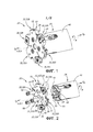
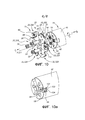
на фиг. 1 показан вид в перспективе поворотного режущего инструмента в соответствии с первым вариантом реализации изобретения по настоящей заявке;in FIG. 1 shows a perspective view of a rotary cutting tool in accordance with a first embodiment of the invention of the present application;
на фиг. 2 показан развернутый вид в перспективе поворотного режущего инструмента, показанного на фиг. 1;in FIG. 2 is an exploded perspective view of the rotary cutting tool shown in FIG. one;
на фиг. 3 показан вид сбоку поворотного режущего инструмента, показанного на фиг. 1 и 2;in FIG. 3 shows a side view of the rotary cutting tool shown in FIG. 1 and 2;
на фиг. 4 показан вид спереди поворотного режущего инструмента, показанного на фиг. 3;in FIG. 4 is a front view of the rotary cutting tool shown in FIG. 3;
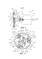
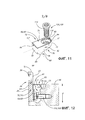
на фиг. 5 показан вид в перспективе держателя инструмента, показанного на фиг. 1 и 2;in FIG. 5 is a perspective view of the tool holder shown in FIG. 1 and 2;
на фиг. 5а показан держатель инструмента по фиг. 5 с удаленным рычагом;in FIG. 5a shows the tool holder of FIG. 5 with a remote lever;
на фиг. 6 показан вид спереди держателя инструмента, показанного на фиг. 5;in FIG. 6 is a front view of the tool holder shown in FIG. 5;
на фиг. 7 показан развернутый вид в перспективе рычага, показанного на фиг. 5;in FIG. 7 is an exploded perspective view of the lever of FIG. 5;
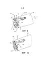
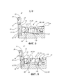
на фиг. 8 показан детализированный продольный вид в разрезе поворотного режущего инструмента по фиг. 1, когда регулируемая режущая часть находится в неизогнутом положении;in FIG. 8 shows a detailed longitudinal sectional view of the rotary cutting tool of FIG. 1 when the adjustable cutting portion is in a non-bent position;
на фиг. 9 показан вид, аналогичный показанному на фиг. 8, когда регулируемая режущая часть находится в изогнутом положении;in FIG. 9 is a view similar to that shown in FIG. 8 when the adjustable cutting portion is in a bent position;
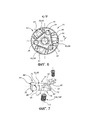
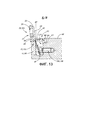
на фиг. 10 показан развернутый вид в перспективе режущего инструмента в соответствии со вторым вариантом реализации изобретения по настоящей заявке;in FIG. 10 is an exploded perspective view of a cutting tool in accordance with a second embodiment of the invention of the present application;
на фиг. 10а показан держатель инструмента по фиг. 10 с удаленным рычагом;in FIG. 10a shows the tool holder of FIG. 10 with remote lever;
на фиг. 11 показан развернутый вид в перспективе рычага, показанного на фиг. 10;in FIG. 11 is an exploded perspective view of the lever of FIG. 10;
на фиг. 12 показан вид поворотного режущего инструмента по фиг. 10, аналогичный виду, показанному на фиг. 8, когда регулируемая режущая часть находится в неизогнутом положении; иin FIG. 12 is a view of the rotary cutting tool of FIG. 10, similar to the view shown in FIG. 8 when the adjustable cutting portion is in a non-bent position; and
на фиг. 13 показан вид, аналогичный показанному на фиг. 12, когда регулируемая режущая часть находится в изогнутом положении.in FIG. 13 is a view similar to that shown in FIG. 12 when the adjustable cutting portion is in a bent position.
Будет понятно, что для простоты и ясности иллюстрации, элементы, показанные на фигурах, не обязательно представлены в масштабе. Например, размеры некоторых элементов могут быть увеличены по отношению к другим элементам для ясности, или некоторые физические компоненты могут быть включены в один функциональный блок или элемент. Кроме того, когда это уместно, ссылочные номера могут повторяться на фигурах для обозначения соответствующих или аналогичных элементов.It will be understood that for simplicity and clarity of illustration, the elements shown in the figures are not necessarily represented to scale. For example, the dimensions of some elements may be increased in relation to other elements for clarity, or some physical components may be included in a single functional unit or element. In addition, when appropriate, reference numbers may be repeated in the figures to indicate corresponding or similar elements.
ОСУЩЕСТВЛЕНИЕ ИЗОБРЕТЕНИЯDETAILED DESCRIPTION OF THE INVENTION
В приведенном ниже описании будут описаны различные аспекты изобретения по настоящей заявке. В целях разъяснения, ниже приведены конкретные конфигурации и особенности достаточно подробно для обеспечения полного понимания изобретения по настоящей заявке. Однако, специалисту в данной области техники будет также понятно, что изобретение по настоящей заявке может быть реализовано на практике без представленных в настоящем документе конкретных конфигураций и особенностей.In the description below, various aspects of the invention will be described herein. For purposes of explanation, the following are specific configurations and features in sufficient detail to provide a thorough understanding of the invention of the present application. However, one skilled in the art will also appreciate that the invention of the present application can be practiced without the specific configurations and features presented herein.
В первую очередь следует обратить внимание на фиг. 1 и 2, показывающие поворотный режущий инструмент 20, отражающий один аспект изобретения по настоящей заявке. В данном неограничивающем примере, показанном на чертежах, поворотный режущий инструмент 20 представляет собой фрезерный режущий инструмент. В частности, фрезерный режущий инструмент представляет собой прорезную фрезу, подходящую для операций прорезного фрезерования. Однако, изобретение по настоящей заявке не ограничено только прорезными фрезами и также может применяться, например, но без ограничения, к торцевым фрезам. Поворотный режущий инструмент 20 имеет продольную ось А инструмента, определяющую переднее и заднее направления DF, DR, и вокруг которой поворотный режущий инструмент 20 выполнен с возможностью поворота в направлении R поворота. В данном неограничивающем примере, показанном на чертежах, поворотный режущий инструмент 20 представляет собой поворотный режущий инструмент правого вращения. Поворотный режущий инструмент 20 содержит корпус 22 инструмента, который обычно может быть выполнен из стали. Поворотный режущий инструмент 20 также содержит держатель 24 инструмента, комплементарный корпусу 22 инструмента. Держатель 24 инструмента также обычно может быть выполнен из стали.First of all, attention should be paid to FIG. 1 and 2, showing a
Следует отметить, что термин «прорезная фреза», используемый в настоящем документе, может быть заменен другими терминами, применяемыми в области резки металлов для таких режущих инструментов, например, «пазовая фреза», «шлицевая фреза», «фреза для желобков», «фреза для пазов», «фреза для канавок», «трехсторонняя фреза», «дисковая прорезная фреза» и т.д.It should be noted that the term "slotted cutter" used in this document can be replaced by other terms used in the field of metal cutting for such cutting tools, for example, "groove cutter", "slotted cutter", "slot cutter", " slot mill "," groove mill "," three-sided mill "," circular slotted mill ", etc.
Следует также отметить, что использование терминов «передний» и «задний» в настоящем описании и формуле изобретения относится к относительному положению в направлении продольной оси А инструмента соответственно влево и вправо по фиг. 3. В настоящем раскрытии термин «передний» соотнесен с режущим концом инструмента.It should also be noted that the use of the terms “front” and “rear” in the present description and the claims refers to the relative position in the direction of the longitudinal axis A of the tool, respectively, left and right in FIG. 3. In the present disclosure, the term “front” is associated with the cutting end of a tool.
Следует также отметить, что использование терминов «осевой» и «радиальный» в настоящем описании и формуле изобретения относится к продольной оси А инструмента, если не указано обратное.It should also be noted that the use of the terms “axial” and “radial” in the present description and claims refers to the longitudinal axis A of the tool, unless otherwise indicated.
Далее обратимся к фиг. 3 и 4. Корпус 22 инструмента имеет центральную ось В корпуса, вокруг которой корпус 22 инструмента выполнен с возможностью поворота в направлении R поворота. Когда корпус 22 инструмента прикреплен с возможностью раскрепления к держателю 24 инструмента, центральная ось В корпуса совпадает с продольной осью А инструмента. Корпус 22 инструмента содержит переднюю и заднюю поверхности 26, 28 корпуса и периферическую поверхность 30 корпуса, которая проходит между передней и задней поверхностями 26, 28 корпуса. Центральная ось В корпуса проходит через переднюю и заднюю поверхности 26, 28 корпуса. В соответствии с некоторыми вариантами реализации изобретения по настоящей заявке, передняя и задняя поверхности 26, 28 могут быть параллельными друг другу. Корпус 22 инструмента может иметь форму диска. Корпус 22 инструмента может иметь осевую симметрию относительно центральной оси В корпуса. В данном неограничивающем варианте реализации, показанном на чертежах, корпус 22 инструмента может иметь тройную осевую симметрию относительно центральной оси В корпуса.Next, refer to FIG. 3 and 4. The
Как показано, в частности, на фиг. 4, корпус 22 инструмента содержит множество режущих частей 32. Множество режущих частей 32 отстоят друг от друга на угловое расстояние относительно продольной оси А инструмента, предпочтительно равномерно. Каждая режущая часть 32 содержит выемку 34 для вставки, расположенную на периферической поверхности 30 корпуса. Каждая выемка 34 для вставки выполнена с возможностью удерживания режущей вставки 36. В данном неограничивающем варианте реализации, показанном на чертежах, углубление 38 для стружки может быть выполнено рядом с каждой выемкой 34 для вставки в направлении R поворота для способствования извлечению стружки. В соответствии с некоторыми вариантами реализации изобретения по настоящей заявке, корпус 22 инструмента может быть выполнен из унифицированной интегральной выполненной заодно конструкции, а каждая режущая вставка 36 может быть установлена непосредственно в корпусе 22 инструмента в соответствующей выемке 34 для вставки. В качестве альтернативы, в соответствии с некоторыми другими вариантами реализации изобретения по настоящей заявке, каждая режущая вставка 36 может быть установлена опосредованно на корпусе 22 инструмента в выемке 34 для вставки, образованной в соответствующем вставном патроне (не показан), который прикреплен с возможностью раскрепления к корпусу 22 инструмента.As shown in particular in FIG. 4, the
Возвращаясь к фиг. 2, каждая режущая вставка 36 может прочно удерживаться в соответствующей выемке 34 для вставки, например, посредством вставного винта 40, взаимодействующим при помощи резьбы с соответствующим отверстием 42 для вставки винта. Каждое отверстие 42 для вставки винта может выходить по меньшей мере на переднюю и заднюю поверхности 26, 28 корпуса. Каждая режущая вставка 36 имеет соответствующую режущую кромку 44. Когда каждая режущая вставка 36 удерживается в соответствующей выемке 34 для вставки, режущая кромка 44 может занимать осевое положение, т.е. в направлении, в целом параллельном продольной оси А инструмента.Returning to FIG. 2, each cutting
Возвращаясь к фиг. 3, поворотный режущий инструмент 20 применяют для фрезеровки пазов в металлической заготовке. Ширина W резания определена размахом перекрывания (в осевом направлении) режущих вставок 36 поворотного режущего инструмента 20 (т.е. в направлении, параллельном продольной оси А инструмента). Управление шириной W резания поворотного режущего инструмента 20 может быть достигнуто при помощи регулировки осевого положения по меньшей мере одной из режущих кромок 44.Следует отметить, что не обязательно регулировать осевое положение всех режущих вставок 36 для регулировки ширины W резания. Следует также отметить, что, как показано на фиг. 4, когда корпус 22 инструмента имеет форму диска, множество режущих кромок 44 могут определять диаметр CD резания относительно продольной оси А инструмента.Returning to FIG. 3, a
Далее обратимся к фиг. 5 и 6, на которых показан держатель 24 инструмента. Держатель 24 инструмента имеет продольную ось Н держателя, вокруг которой держатель 24 инструмента выполнен с возможностью поворота в направлении R поворота. Когда корпус 22 инструмента прикреплен с возможностью раскрепления к держателю 24 инструмента, продольная ось Н держателя совпадает с продольной осью А инструмента. Держатель 24 инструмента содержит периферическую поверхность 46 держателя, которая проходит по окружности вдоль продольной оси А инструмента. Периферическая поверхность 46 держателя образует границу передней поверхности 48 держателя на переднем конце 50 держателя 24 инструмента. Продольная ось Н держателя проходит через переднюю поверхность 48 держателя. Держатель 24 инструмента может быть удлинен в направлении продольной оси А инструмента. Держатель 24 инструмента может иметь осевую симметрию относительно продольной оси Н держателя. В данном неограничивающем варианте реализации, показанном на чертежах, держатель 24 инструмента может иметь тройную осевую симметрию относительно продольной оси Н держателя. Следует отметить, что периферическая поверхность 46 держателя 24 инструмента смещена в радиальном внутреннем направлении по отношению к режущим вставкам 36, таким образом обеспечивая возможность резки прорези без взаимодействия держателя 24 инструмента с заготовкой.Next, refer to FIG. 5 and 6, which show the
Возвращаясь к фиг. 1 и 2, корпус 22 инструмента прикреплен с возможностью раскрепления к держателю 24 инструмента в переднем конце 50 держателя. В соответствии с некоторыми вариантами реализации изобретения по настоящей заявке, передняя поверхность 48 держателя может содержать поверхность 52 упора держателя. Передняя поверхность 48 держателя может содержать по меньшей мере одно резьбовое отверстие 54 держателя, выполненное в ней. Корпус 22 инструмента может содержать по меньшей мере одно сквозное отверстие 56 корпуса, которое выходит на переднюю и заднюю поверхности 26, 28 корпуса. Удерживающий винт 58 может быть расположен в каждом сквозном отверстии 56 корпуса и может быть принят с резьбовым взаимодействием в соответствующем резьбовом отверстии 54 держателя. Поверхность 52 упора держателя может упираться в часть задней поверхности 28 корпуса.Returning to FIG. 1 and 2, the
В соответствии с некоторыми вариантами реализации изобретения по настоящей заявке, корпус 22 инструмента имеет обратный ход. Иными словами, передняя поверхность 26 корпуса может функционировать как задняя поверхность 28 корпуса (и наоборот), а когда корпус 22 инструмента и держатель 24 инструмента прикреплены друг к другу с возможностью раскрепления, поверхность 52 упора держателя может упираться в часть передней поверхности 26 корпуса. В такой конфигурации поворотный режущий инструмент 20 становится поворотным режущим инструментом левого вращения.In accordance with some embodiments of the invention of the present application, the
Возвращаясь к фиг. 5 и 6, держатель 24 инструмента содержит регулировочную конструкцию 60 для регулировки осевого положения соответствующей выемки 34 для вставки и, таким образом, осевого положения режущей вставки 36, установленной в соответствующей выемке 34 для вставки. Регулировочная конструкция 60 содержит смещающий элемент 62. Смещающий элемент 62 содержит смещающую часть 64. Смещающий элемент 62 прикреплен с возможностью перемещения к держателю 24 инструмента. Смещающая часть 64 выполнена с возможностью перемещения относительно передней поверхности 48 держателя. В соответствии с некоторыми вариантами реализации изобретения по настоящей заявке, смещающий элемент 62 может быть прикреплен с возможностью раскрепления к держателю 24 инструмента. На виде спереди держателя 24 инструмента (т.е. на фиг. 6) смещающая часть 64 может быть расположена на периферии держателя 24 инструмента (т.е. рядом с периферической поверхностью 46 держателя). Следует отметить, что смещающий элемент 62 может не быть выполнен заодно с держателем 24 инструмента. Очевидно, при этом смещающий элемент 62 не выполнен заодно с корпусом 22 инструмента.Returning to FIG. 5 and 6, the
Множество режущих частей 32 содержит регулируемую режущую часть 32А. Регулируемая режущая часть 32А поворотно выровнена с регулировочной конструкцией 60 и может рассматриваться как связанная с ней. Регулируемая режущая часть 32А выполнена с возможностью регулировки между неизогнутым положением и изогнутым положением при помощи регулировочной конструкцией 60. Когда регулируемая режущая часть 32А находится в неизогнутом положении, регулируемая режущая часть 32А может не находиться в смещающем взаимодействии со смещающей частью 64 и не испытывать упругую деформацию. Задняя поверхность 28 корпуса, расположенная на регулируемой режущей части 32А, образует плоскость BP корпуса, перпендикулярную продольной оси А инструмента. Когда регулируемая режущая часть 32А находится в изогнутом положении, смещающая часть 64 проходит дальше в прямом направлении по оси, чем плоскость BP корпуса. Таким образом, регулируемая режущая часть 32А упруго деформирована в переднем направлении DF вследствие смещающего взаимодействия со смещающей частью 64. Далее в настоящем описании подробно описан способ регулировки регулируемой режущей части 32А между неизогнутым положением и изогнутым положением.The plurality of cutting parts 32 comprise an adjustable cutting part 32A. The adjustable cutting portion 32A is pivotally aligned with the adjusting
В соответствии с некоторыми вариантами реализации изобретения по настоящей заявке, множество режущих частей 32 может содержать нерегулируемую режущую часть 32В, которая выполнена без возможности регулировки между неизогнутым положением и изогнутым положением. Нерегулируемая режущая часть 32В не связана с какой-либо регулировочной конструкцией 60. Когда корпус 22 инструмента прикреплен с возможностью раскрепления к держателю 24 инструмента, каждое сквозное отверстие 56 корпуса и каждый удерживающий винт 58 могут быть расположены в соответствующей нерегулируемой режущей части 32В. Таким образом, регулируемая режущая часть 32А может быть свободна изогнута.In accordance with some embodiments of the invention, the plurality of cutting portions 32 may include an unregulated cutting portion 32B that is incapable of adjusting between an unbent position and a bent position. The non-adjustable cutting portion 32B is not associated with any adjusting
В соответствии с некоторыми вариантами реализации изобретения по настоящей заявке, множество режущих частей 32 может содержать по меньшей мере одну дополнительную регулируемую режущую часть 32А, таким образом образуя множество регулируемых режущих частей 32А. Множество режущих частей 32 может содержать по меньшей мере одну дополнительную нерегулируемую режущую часть 32B, таким образом образуя множество нерегулируемых режущих частей 32B. Держатель 24 инструмента может содержать по меньшей мере одну дополнительную регулировочную конструкцию 60 для образования множества регулировочных конструкций 60. Каждая регулировочная конструкция 60 связана с соответствующей регулируемой режущей частью 32А. Множество регулируемых режущих частей 32А и множество нерегулируемых режущих частей 32B могут быть расположены поочередно вдоль периферической поверхности 30 корпуса. Выемка 34 для вставки каждой регулируемой режущей части 32А может выходить сбоку на переднюю поверхность 26 корпуса, а выемка 34 для вставки каждой нерегулируемой режущей части 32B может выходить вбок на заднюю поверхность 28 корпуса.In accordance with some embodiments of the invention, the plurality of cutting parts 32 may include at least one additional adjustable cutting part 32A, thereby forming a plurality of adjustable cutting parts 32A. The plurality of cutting parts 32 may comprise at least one additional non-adjustable cutting part 32B, thereby forming a plurality of non-adjustable cutting parts 32B. The
Следует отметить, что не обязательно регулировать осевое положение режущих вставок 36 для всех регулируемых режущих вставок 32А, даже если каждая регулируемая режущая вставка 32А связана с соответствующей регулировочной конструкцией 60.It should be noted that it is not necessary to adjust the axial position of the cutting inserts 36 for all adjustable cutting inserts 32A, even if each adjustable cutting insert 32A is associated with a
Следует также отметить, что любой признак в описании, который относится к регулируемой режущей части 32А, может также, при необходимости, относиться к любой другой режущей части из множества регулируемых режущих частей 32А. Аналогичным образом, любой признак в описании, который относится к нерегулируемой режущей части 32B, может также, при необходимости, относиться к любой другой режущей части из множества нерегулируемых режущих частей 32B, и любой признак в описании, который относится к регулировочной конструкции 60, может относиться к любой другой режущей части из множества регулируемых режущих частей 60.It should also be noted that any feature in the description that relates to the adjustable cutting part 32A may also, if necessary, refer to any other cutting part of the plurality of adjustable cutting parts 32A. Similarly, any feature in the description that relates to the non-adjustable cutting portion 32B may also, if necessary, apply to any other cutting portion of the plurality of non-adjustable cutting parts 32B, and any feature in the description that relates to the adjusting
Далее обратимся к фиг. 1-2 и 4. В соответствии с некоторыми вариантами реализации изобретения по настоящей заявке, регулируемая режущая часть 32А может содержать эластичное углубление 66. Эластичное углубление 66 выполнено с возможностью обеспечения изгиба регулируемой режущей части 32А посредством смещающего усилия BF, приложенного при помощи смещающей части 64. Эластичное углубление 66 может выходить по меньшей мере на переднюю и заднюю поверхности 26, 28 корпуса. Эластичное углубление 66 может также выходить на периферическую поверхность 30 корпуса. В конкретном варианте реализации эластичное углубление 66 может выходить на периферическую поверхность 30 корпуса в передней в поворотном направлении части выемки 34 для вставки регулируемой режущей части 32А.Next, refer to FIG. 1-2 and 4. In accordance with some embodiments of the invention, the adjustable cutting portion 32A may comprise an
Как показано на фиг 4, в некоторых вариантах реализации на виде спереди поворотного режущего инструмента 20 эластичное углубление 66 может проходить в радиальном направлении. Нерегулируемая режущая часть 32B может быть лишена эластичного углубления 66, так как она не связана с регулировочной конструкцией 60 и не выполнена с возможностью изгиба. Эластичное углубление 66 может быть выполнено между регулируемой режущей частью 32А и расположенной рядом нерегулируемой режущей частью 32B в направлении R поворота. Эластичное углубление 66 может проходить радиально внутрь к области на корпусе 22 инструмента, расположенной на расстоянии от центральной оси В корпуса, составляющем приблизительно одну треть радиуса, связанного с диаметром CD резания.As shown in FIG. 4, in some embodiments of the front view of the
Далее обратимся к фиг. 7. В соответствии с некоторыми вариантами реализации изобретения по настоящей заявке, смещающий элемент 62 может представлять собой рычаг 68, прикрепленный с возможностью поворота к держателю 24 инструмента. Рычаг 68 может быть выполнен из стали. Рычаг 68 может проходить в продольном направлении вдоль продольной оси LA рычага. Рычаг 68 может содержать две противолежащие концевые поверхности 70 рычага, пересекаемые продольной осью LA рычага, и периферическую поверхность 72 рычага, проходящую между концевыми поверхностями 70 рычага. Периферическая поверхность 72 рычага может содержать противолежащие верхнюю и нижнюю поверхности 74, 76 рычага и две противолежащие боковые поверхности 78 рычага, соединяющие верхнюю и нижнюю поверхности 74, 76 рычага. Рычаг 68 может содержать приводную часть 80 рычага и среднюю часть 82 рычага, расположенную между смещающей частью 64 и приводной частью 80 рычага. Смещающая часть 64 может быть расположена на одном конце рычага 68, а приводная часть 80 рычага может быть расположена на другом конце рычага 68. Средняя часть 82 рычага может содержать по меньшей мере одну поворотную поверхность 84 рычага, которая может быть выполнена с возможностью установки с возможностью поворота по меньшей мере на одной опорной поверхности 84 на держателе 24 инструмента.Next, refer to FIG. 7. In accordance with some embodiments of the invention, the biasing
В соответствии с некоторыми вариантами реализации изобретения по настоящей заявке, рычаг 68 может быть выполнен таким образом, что смещающая часть 64 может входить в смещающее взаимодействие с регулируемой режущей частью 32А, когда рычаг 68 поворачивают вокруг оси Р поворота посредством приложения приводного усилия AF к приводной части 80 рычага. Иными словами, смещающая часть 64 может прилагать смещающее усилие BF к регулируемой режущей части 32А при повороте рычага 68. Направление смещающего усилия BF может быть по существу параллельным продольной оси А инструмента. Ось Р поворота может быть перпендикулярна продольной оси А инструмента. По меньшей мере одна поворотная поверхность 84 рычага может располагаться на части воображаемой цилиндрической поверхности CS, имеющей ось С цилиндра. Ось Р поворота и ось С цилиндра могут совпадать. Аналогичным образом, по меньшей мере одна опорная поверхность 84 рычага может располагаться на воображаемой цилиндрической поверхности CS. Таким образом, по меньшей мере одна опорная поверхность 84 и по меньшей мере одна поворотная поверхность 84 могут плавно перемещаться друг по другу, когда рычаг 68 поворачивают вокруг оси Р поворота.In accordance with some embodiments of the present invention, the
Как показано на фиг. 5 и 7, в соответствии с некоторыми вариантами реализации изобретения по настоящей заявке, рычаг 68 может содержать два плеча 88 рычага, проходящих от двух противолежащих боковых поверхностей 78 рычага, соответственно, рядом с одной из концевых поверхностей 70 рычага. Как показано на фиг. 7, рычаг 68 может содержать точно две поворотных поверхности 84 рычага, по одной на каждом плече 88 рычага. Рычаг 68 может содержать резьбовое отверстие 92 рычага. Резьбовое отверстие 92 рычага используется для обеспечения поворота рычага 68 и описано подробно далее в настоящем описании.As shown in FIG. 5 and 7, in accordance with some embodiments of the present invention, the
Как показано на фиг. 11, в соответствии со вторым вариантом реализации изобретения по настоящей заявке, нижняя поверхность 76 рычага может содержать выступ 90 рычага, который проходит в поперечном направлении (т.е. поперечном продольной оси LA рычага) между двумя боковыми поверхностями 78 рычага. Рычаг 68 может содержать лишь одну поворотную поверхность 84 рычага, которая расположена на выступе 90 рычага. Рычаг 68 может содержать сквозное отверстие 94 рычага, проходящее между верхней и нижней поверхностями 74, 76 рычага. Сквозное отверстие 94 рычага используется для обеспечения поворота рычага 68 и описано подробно далее в настоящем описании.As shown in FIG. 11, in accordance with a second embodiment of the invention, the
В соответствии с некоторыми вариантами реализации изобретения по настоящей заявке, регулировочная конструкция 60 может также содержать канал 96 рычага, который выполнен с возможностью вмещения рычага 68. Канал 96 рычага углублен в держателе 24 инструмента на передней поверхности 48 держателя. Канал 96 рычага может проходить в продольном направлении. Канал 96 рычага может содержать две противолежащие боковые поверхности 98 канала рычага и центральную поверхность 100 канала рычага, которая проходит между двумя боковыми поверхностями 98 канала рычага. По меньшей мере одна опорная поверхность 84 может быть расположена в канале 96 рычага.In accordance with some embodiments of the invention, the
Как показано на фиг. 5а, в соответствии с первым вариантом реализации изобретения по настоящей заявке, канал 96 рычага может быть углублен в периферической поверхности 46 держателя и может выходить на переднюю поверхность 48 держателя. Канал 96 рычага может проходить в осевом направлении относительно продольной оси А инструмента.As shown in FIG. 5a, in accordance with a first embodiment of the invention of the present application, the
Как показано на фиг. 10а, в соответствии со вторым вариантом реализации изобретения по настоящей заявке, канал 96 рычага может быть углублен в передней поверхности 48 держателя. Канал 96 рычага может выходить на периферическую поверхность 46 держателя. Канал 96 рычага может проходить в радиальном направлении относительно продольной оси А инструмента. Центральная поверхность 100 канала рычага может содержать проходящее в осевом направлении резьбовое отверстие 102 канала, углубленное в центральной поверхности 100 канала рычага. Назначение резьбового отверстия 102 канала описано подробно далее в настоящем описании. В отличие от первого варианта реализации, в конфигурации в соответствии со вторым вариантом реализации длина L канала 96 рычага и, таким образом, рычаг 68 ограничены радиальным размером передней поверхности 48 держателя.As shown in FIG. 10a, in accordance with a second embodiment of the invention of the present application, the
В соответствии с некоторыми вариантами реализации изобретения по настоящей заявке, канал 96 рычага может содержать по меньшей мере одну канавку 104 канала.In accordance with some embodiments of the invention of the present application, the
В соответствии с первым вариантом реализации изобретения по настоящей заявке, канал 96 рычага может содержать две канавки 104 канала, которые проходят от двух противолежащих боковых поверхностей 98 канала рычага, соответственно, и выходят на переднюю поверхность 48 держателя. Две канавки 104 канала могут выходить на периферическую поверхность 46 держателя. Канал 96 рычага может содержать точно две опорные поверхности 86, по одной опорной поверхности 86, расположенной в каждой канавке 104 канала.According to a first embodiment of the invention according to the present application, the
В соответствии со вторым вариантом реализации изобретения по настоящей заявке, канал 96 рычага может содержать одну канавку 100 канала, которая углублена в центральной поверхности 100 канала рычага. Канавка 104 канала может проходить в поперечном направлении между двумя боковыми поверхностями 98 канала рычага. Канал 96 рычага может содержать лишь одну опорную поверхность 86, которая расположена в канавке 104 канала.According to a second embodiment of the invention, the
В соответствии с некоторыми вариантами реализации изобретения по настоящей заявке, регулировочная конструкция 60 может содержать приводной элемент 106, который выполнен с возможностью обеспечивать поворот рычага 68 при приведении в действие. Приводной элемент 106 может представлять собой приводной винт 108.In accordance with some embodiments of the present invention, the adjusting
Как показано на фиг. 19, в соответствии со вторым вариантом реализации изобретения по настоящей заявке, корпус 22 инструмента может содержать сквозное отверстие 112 для обеспечения доступа, которое выходит на переднюю и заднюю поверхности 26, 28 корпуса. Сквозное отверстие 112 для обеспечения доступа может быть поворотно выровнено с приводным винтом 108, таким образом обеспечивая возможность доступа к приводному винту 108 для его затягивания и ослабления.As shown in FIG. 19, in accordance with a second embodiment of the invention of the present application, the
В соответствии с первым вариантом реализации изобретения по настоящей заявке, приводной винт 108 может содержать контактную поверхность 110 винта на одном конце. Регулировка регулируемой режущей части 32А из неизогнутого положения в изогнутое положение выполняется посредством проведения следующих этапов. Рычаг 68 располагают в канале 96 рычага. Приводной винт 108 вводят в резьбовое взаимодействие в резьбовом отверстии 92 рычага, пока контактная поверхность 110 винта изначально находится в контакте с центральной поверхностью 100 канала рычага, таким образом определяя неизогнутое положение (см. фиг. 8). В данном положении смещающая часть 64 расположена сзади в осевом направлении от плоскости BP корпуса. Дальнейшее затягивание приводного винта 108 обеспечивает перемещение приводной части 80 рычага от центральной поверхности 100 канала рычага и рычаг 68 поворачивается вокруг оси Р поворота в поворотном направлении D вращения до тех пор, пока смещающая часть 64 находится в начальном контакте с регулируемой режущей частью 32А. В данном положении контактная поверхность 110 винта начинает нажимать на центральную поверхность 100 канала рычага. Когда приводной винт 108 затягивают далее, рычаг 68 поворачивается вокруг оси Р поворота в поворотном направлении D вращения. Во время поворотного перемещения смещающая часть 64 смещается в направлении, имеющем передний компонент, до тех пор, пока смещающая часть 64 проходит далее в осевом направлении вперед, чем плоскость BP корпуса, определяя изогнутое положение (см. фиг. 9). Таким образом, регулируемая режущая часть 32А упруго деформирована в переднем направлении DF вследствие смещающего взаимодействия со смещающей частью 64.According to a first embodiment of the invention of the present application, the drive screw 108 may comprise a
В соответствии со вторым вариантом реализации изобретения по настоящей заявке, приводной винт 108 может содержать головку 114 винта, а сквозное отверстие 94 рычага может содержать контактную поверхность 116 винта рычага. Регулировка регулируемой режущей части 32А из неизогнутого положения в изогнутое положение выполняется посредством проведения следующих этапов. Рычаг 68 располагают в канале 96 рычага. Приводной винт 108 располагают в сквозном отверстии 92 рычага и вводят в резьбовое взаимодействие в резьбовом отверстии 102 канала, определяя неизогнутое положение (см. фиг. 12). В данном положении смещающая часть 64 расположена сзади в осевом направлении от плоскости BP корпуса. Дальнейшее затягивание приводного винта 108 обеспечивает прижатие головки винта 114 к контактной поверхности 116 винта рычага и обеспечивает перемещение приводной части 80 рычага к центральной поверхности 100 канала рычага таким образом, что рычаг 68 поворачивается вокруг оси Р поворота в поворотном направлении D вращения до тех пор, пока смещающая часть 64 находится в начальном контакте с регулируемой режущей частью 32А. Когда приводной винт 108 затягивают далее, рычаг 68 поворачивается далее вокруг оси Р поворота в поворотном направлении D вращения. Во время указанного поворотного перемещения смещающая часть 64 смещается в направлении, имеющем передний компонент, до тех пор, пока смещающая часть 64 проходит далее в осевом направлении вперед, чем плоскость BP корпуса, определяя изогнутое положение (см. фиг. 13). Таким образом, регулируемая режущая часть 32А упруго деформирована в переднем направлении DF вследствие смещающего взаимодействия со смещающей частью 64.According to a second embodiment of the invention, the drive screw 108 may comprise a
В соответствии с первым вариантом реализации изобретения по настоящей заявке, регулировочная конструкция 60 может содержать первый механизм для предотвращения осевого перемещения рычага 68 в переднем направлении. Приводная часть 80 рычага имеет ширину W1 рычага. Средняя часть канала 96 рычага имеет ширину W2 канала рычага. Ширина W2 канала рычага может быть меньше, чем ширина W1 рычага, таким образом предотвращая смещение рычага 68 в переднем направлении по оси. Кроме того, регулировочная конструкция 60 может содержать второй механизм для предотвращения радиального перемещения рычага 68 в наружном направлении. Как показано на фиг. 9, регулировочная конструкция 60 может содержать радиальный стопорный элемент 118, прикрепленный к держателю 24 инструмента с возможностью раскрепления. Рычаг 68 может содержать вырез 120 на одном своем конце. Радиальный стопорный элемент 118 может быть выполнен таким образом, что он преграждает путь рычага 68 в вырезе 120, когда рычаг 68 смещен в радиальном наружном направлении.According to a first embodiment of the invention of the present application, the adjusting
Следует отметить, что регулировочная конструкция 60, и в частности смещающий элемент 62, не выполнен заодно с корпусом 22 инструмента, и не встроен в него. Иными словами, регулировочная конструкция 60 является внешней по отношению к корпусу 22 инструмента. Это является преимущественным, когда поворотный режущий инструмент 20 является малым (например, диаметр CD резания равен приблизительно 40 мм или менее, когда ширина W резания может составлять приблизительно 2 мм или менее), так как корпус 22 инструмента не имеет достаточной площади для размещения какого-либо типа регулировочной конструкции 60.It should be noted that the
Таким образом, поворотный инструмент 20 имеет продольную ось А поворота инструмента и содержит: первую часть инструмента (т.е. держатель 24 инструмента), имеющую продольную ось Н инструмента; вторую часть инструмента (т.е. корпус 22 инструмента), имеющую центральную ось В корпуса; при этом корпус 22 инструмента прикреплен с возможностью раскрепления к держателю 24 инструмента так, что центральная ось В корпуса и продольная ось Н держателя совпадают с продольной осью А инструмента; по меньшей мере одну режущую вставку 36, установленную на корпусе 22 инструмента; и рычаг 68, установленный с возможностью поворота на держателе 24 инструмента и выполненный с возможностью регулировки осевого положения по меньшей мере одной режущей вставки 36, установленной на корпусе 22 инструмента.Thus, the
Следует также отметить, что в изогнутом положении рычаг 68 может не проходить за периферическую поверхность 46 держателя (т.е. из канала 96 рычага) в радиальном наружном направлении. Таким образом, рычаг 68 предпочтительно не взаимодействует с глубиной резания поворотного режущего инструмента 20.It should also be noted that in the bent position, the
Следует также отметить, что особенностью изобретения по настоящей заявке является то, что обеспечено очень точное осевое расположение режущих вставок 22. Таким образом, в прорезных фрезах шириной W резания поворотного режущего инструмента 20 можно управлять с большой точностью.It should also be noted that a feature of the invention of the present application is that a very precise axial arrangement of the cutting inserts 22 is provided. Thus, in the slotted milling cutters of the cutting width W of the
Хотя изобретение по настоящей заявке было описано с определенной степенью конкретности, следует понимать, что различные изменения и модификации могут быть выполнены без выхода за пределы сущности или объема изобретения, определенного прилагаемой формулой изобретения.Although the invention of the present application has been described with a certain degree of specificity, it should be understood that various changes and modifications can be made without going beyond the essence or scope of the invention defined by the attached claims.
Claims (73)
Applications Claiming Priority (3)
| Application Number | Priority Date | Filing Date | Title |
|---|---|---|---|
| US14/847,258 | 2015-09-08 | ||
| US14/847,258 US10183347B2 (en) | 2015-09-08 | 2015-09-08 | Rotary cutting tool having axial position adjustment arrangement |
| PCT/IL2016/050866 WO2017042798A1 (en) | 2015-09-08 | 2016-08-09 | Rotary cutting tool having axial position adjustment arrangement |
Publications (1)
| Publication Number | Publication Date |
|---|---|
| RU2707843C1 true RU2707843C1 (en) | 2019-11-29 |
Family
ID=56936458
Family Applications (1)
| Application Number | Title | Priority Date | Filing Date |
|---|---|---|---|
| RU2018101972A RU2707843C1 (en) | 2015-09-08 | 2016-08-09 | Rotary cutting tool comprising structure for adjusting axial position |
Country Status (9)
| Country | Link |
|---|---|
| US (1) | US10183347B2 (en) |
| EP (1) | EP3347153B1 (en) |
| JP (1) | JP6802252B2 (en) |
| KR (1) | KR102467235B1 (en) |
| CN (1) | CN107949449B (en) |
| CA (1) | CA2992527C (en) |
| IL (1) | IL257218B (en) |
| RU (1) | RU2707843C1 (en) |
| WO (1) | WO2017042798A1 (en) |
Families Citing this family (7)
| Publication number | Priority date | Publication date | Assignee | Title |
|---|---|---|---|---|
| KR102036975B1 (en) * | 2015-06-15 | 2019-10-25 | 오에스지 가부시키가이샤 | reamer |
| CN107614172B (en) * | 2015-06-15 | 2019-03-01 | Osg株式会社 | T-slot cutter |
| DE102015115310A1 (en) | 2015-09-10 | 2017-03-16 | Hartmetall-Werkzeugfabrik Paul Horn Gmbh | whirling tool |
| KR101672298B1 (en) * | 2015-12-23 | 2016-11-03 | 주식회사 포스코 | Apparatus for cutting a hrsa |
| EP3456446A1 (en) * | 2017-09-15 | 2019-03-20 | Sandvik Intellectual Property AB | Cutting tool part assembly |
| US11890688B1 (en) | 2022-08-04 | 2024-02-06 | Iscar, Ltd. | Rotary cutting tool having an integrally formed axial adjustment tongue |
| KR102652633B1 (en) * | 2023-09-26 | 2024-03-29 | 주식회사 데카메탈 | Cutting tool for face cutting apparatus |
Citations (5)
| Publication number | Priority date | Publication date | Assignee | Title |
|---|---|---|---|---|
| SU1159727A1 (en) * | 1983-10-10 | 1985-06-07 | Nagajtsev Vladimir F | Disc-type milling cutter |
| SU1690968A1 (en) * | 1989-10-27 | 1991-11-15 | Московское станкостроительное производственное объединение "Красный пролетарий" | End cutter |
| SU1779486A1 (en) * | 1990-12-27 | 1992-12-07 | Proizv Ob Mekh Avtom Proizv Ma | Milling cutter |
| US6604894B1 (en) * | 2002-03-08 | 2003-08-12 | Valenite Inc. | Rotatable cutting tool |
| US20150202698A1 (en) * | 2014-01-22 | 2015-07-23 | Kennametal Inc. | Cutting tool having insert pocket with cantilevered member |
Family Cites Families (43)
| Publication number | Priority date | Publication date | Assignee | Title |
|---|---|---|---|---|
| US2322579A (en) * | 1942-06-27 | 1943-06-22 | Kutscha Alois | Milling cutter assembly |
| US3091138A (en) * | 1959-12-07 | 1963-05-28 | Wesson Corp | Rotating cutter assembly |
| US3077025A (en) * | 1961-02-17 | 1963-02-12 | Schiess Ag | Cutter head |
| US3323194A (en) * | 1965-01-04 | 1967-06-06 | Walter J Greenleaf | Milling cutter |
| SE382000B (en) * | 1972-05-26 | 1976-01-12 | Sandvik Ab | MILLING TOOL |
| DE2615913A1 (en) | 1976-04-10 | 1977-10-20 | Ingersoll Mach & Tool Co | Cutter head with roughing and finishing cutters - has roughing cutters lowered by externally operated wedge system for initial machining |
| US4547100A (en) * | 1983-09-28 | 1985-10-15 | The Valeron Corporation | Adjustable milling cutter |
| SU1419827A1 (en) * | 1986-07-04 | 1988-08-30 | Всесоюзный научно-исследовательский и проектный институт тугоплавких металлов и твердых сплавов | Face-milling cutter |
| US5102269A (en) * | 1989-06-20 | 1992-04-07 | Mitsubishi Materials Corporation | Insert cutter |
| CZ278929B6 (en) * | 1989-10-10 | 1994-09-14 | Rezabek Ladislav | Segment finishing face-milling cutter for plane milling |
| DE9306418U1 (en) * | 1993-04-28 | 1993-07-01 | Prekwinkel Maschinen- Und Werkzeugbau, 4900 Herford, De | |
| ATE170118T1 (en) * | 1994-02-19 | 1998-09-15 | Kennametal Hertel Ag | CUTTER |
| DE4431841C2 (en) * | 1994-09-07 | 1997-10-23 | Walter Ag | Method and use of a disk carrier for producing deep grooves in generator and turbine engines |
| DE19725219C2 (en) * | 1997-06-15 | 1999-05-20 | Walter Ag | Milling tool with axial adjustment of the insert seat |
| US6056484A (en) | 1998-08-07 | 2000-05-02 | Kennametal Inc. | Device and method for adjusting the position of cutting inserts mounted in a cutting tool |
| IL127827A (en) * | 1998-12-29 | 2001-08-08 | Iscar Ltd | Slotting cutter |
| DE10011113A1 (en) * | 2000-03-09 | 2001-09-13 | Komet Stahlhalter Werkzeuge | Machine tool, e.g. disc miller cutter; has support body with outer adjusting section connected to central section by elastic bridge and adjustment component to adjust cutting plate radially |
| SE516612C2 (en) * | 2000-06-27 | 2002-02-05 | Sandvik Ab | Adjusting mechanism for a cutter as well as tools for chip separating machining |
| IL144090A0 (en) * | 2001-07-02 | 2002-05-23 | Iscar Ltd | Cutting tool with two edge-on mounted inserts |
| IL154472A (en) | 2003-02-16 | 2007-10-31 | Amir Satran | Cutting tool and cartridge therefor |
| DE202004008642U1 (en) | 2004-05-27 | 2005-09-29 | Kennametal Inc. | milling tool |
| IL165620A (en) * | 2004-12-07 | 2009-05-04 | Iscar Ltd | Milling cutter |
| JP2008155352A (en) * | 2006-12-26 | 2008-07-10 | Sumitomo Electric Hardmetal Corp | Cutting edge replaceable cutter with adjusting mechanism |
| JP2009095894A (en) * | 2007-10-12 | 2009-05-07 | Sumitomo Electric Hardmetal Corp | Cutting edge adjusting mechanism and cutting tool using the same |
| SE531505C2 (en) * | 2007-11-14 | 2009-04-28 | Seco Tools Ab | Cutting tools and cutting tools |
| IL190734A (en) | 2008-04-08 | 2013-08-29 | Iscar Ltd | Adjustment mechanism |
| EP2291258B1 (en) * | 2008-06-13 | 2016-12-21 | TaeguTec Ltd. | Cutting tool and cartridge for the same |
| EP2691767B1 (en) * | 2011-03-31 | 2016-03-23 | GE Healthcare Bio-Sciences AB | Method for sample preparation |
| CN103608142B (en) * | 2011-06-17 | 2016-08-24 | 株式会社钨钛合金 | Cutting tip and rotary cutting tool |
| US9216461B2 (en) | 2011-07-19 | 2015-12-22 | Iscar, Ltd. | Cutting body configured for fine-tuning and metal-working machine tool comprising a plurality thereof |
| TWM424204U (en) | 2011-08-15 | 2012-03-11 | Urox Tools Prec Industry Co Ltd | Adjustable milling cutter base structure |
| CN202291575U (en) | 2011-10-12 | 2012-07-04 | 益壮企业有限公司 | T-shaped milling cutter |
| JP2013111699A (en) * | 2011-11-29 | 2013-06-10 | Mitsubishi Materials Corp | Fine adjustment type cutting tool |
| US9616585B2 (en) * | 2012-07-12 | 2017-04-11 | Iscar, Ltd. | Slitting tool configured for fine-tuning |
| US8851807B2 (en) | 2012-12-26 | 2014-10-07 | Iscar, Ltd. | Cutting tool having axial position adjustment arrangement |
| CN203209761U (en) * | 2013-04-08 | 2013-09-25 | 河南富耐克超硬材料股份有限公司 | Adjustable precision milling cutter |
| KR101500152B1 (en) * | 2013-09-25 | 2015-03-18 | 한국야금 주식회사 | Milling Cutting Tool |
| US9676044B2 (en) * | 2013-12-19 | 2017-06-13 | Iscar, Ltd. | Rotary cutting tool having disk-shaped cutter body provided with support pads |
| EP2929967B1 (en) * | 2014-04-11 | 2017-02-01 | Sandvik Intellectual Property AB | A slot milling disc and a rotatable mounting shaft for such a milling disc |
| US9427811B2 (en) * | 2014-05-07 | 2016-08-30 | Iscar, Ltd. | Rotary slitter with cutting insert edge positioning arrangement |
| DE202014102904U1 (en) | 2014-06-25 | 2015-06-26 | Pokolm Frästechnik GmbH & Co. KG | Face mill with a rotating body mounted around a vertical axis |
| CN204248059U (en) * | 2014-11-25 | 2015-04-08 | 株洲钻石切削刀具股份有限公司 | A kind of rotary cutter |
| CN204430306U (en) * | 2015-02-03 | 2015-07-01 | 成都成林数控刀具有限公司 | A kind of boring cutter system with fine-adjusting unit |
-
2015
- 2015-09-08 US US14/847,258 patent/US10183347B2/en active Active
-
2016
- 2016-08-09 JP JP2018502213A patent/JP6802252B2/en active Active
- 2016-08-09 CN CN201680051359.9A patent/CN107949449B/en active Active
- 2016-08-09 CA CA2992527A patent/CA2992527C/en active Active
- 2016-08-09 KR KR1020187008265A patent/KR102467235B1/en active IP Right Grant
- 2016-08-09 RU RU2018101972A patent/RU2707843C1/en active
- 2016-08-09 EP EP16766399.6A patent/EP3347153B1/en active Active
- 2016-08-09 WO PCT/IL2016/050866 patent/WO2017042798A1/en active Application Filing
-
2018
- 2018-01-29 IL IL257218A patent/IL257218B/en active IP Right Grant
Patent Citations (5)
| Publication number | Priority date | Publication date | Assignee | Title |
|---|---|---|---|---|
| SU1159727A1 (en) * | 1983-10-10 | 1985-06-07 | Nagajtsev Vladimir F | Disc-type milling cutter |
| SU1690968A1 (en) * | 1989-10-27 | 1991-11-15 | Московское станкостроительное производственное объединение "Красный пролетарий" | End cutter |
| SU1779486A1 (en) * | 1990-12-27 | 1992-12-07 | Proizv Ob Mekh Avtom Proizv Ma | Milling cutter |
| US6604894B1 (en) * | 2002-03-08 | 2003-08-12 | Valenite Inc. | Rotatable cutting tool |
| US20150202698A1 (en) * | 2014-01-22 | 2015-07-23 | Kennametal Inc. | Cutting tool having insert pocket with cantilevered member |
Also Published As
| Publication number | Publication date |
|---|---|
| KR20180048755A (en) | 2018-05-10 |
| BR112018002458A2 (en) | 2018-09-18 |
| CA2992527C (en) | 2023-09-19 |
| EP3347153A1 (en) | 2018-07-18 |
| CA2992527A1 (en) | 2017-03-16 |
| IL257218A (en) | 2018-03-29 |
| JP2018530438A (en) | 2018-10-18 |
| US20170066066A1 (en) | 2017-03-09 |
| IL257218B (en) | 2021-04-29 |
| CN107949449B (en) | 2019-11-05 |
| WO2017042798A1 (en) | 2017-03-16 |
| KR102467235B1 (en) | 2022-11-16 |
| JP6802252B2 (en) | 2020-12-16 |
| EP3347153B1 (en) | 2024-03-27 |
| CN107949449A (en) | 2018-04-20 |
| US10183347B2 (en) | 2019-01-22 |
Similar Documents
| Publication | Publication Date | Title |
|---|---|---|
| RU2707843C1 (en) | Rotary cutting tool comprising structure for adjusting axial position | |
| EP2734329B1 (en) | Cutting body configured for fine-tuning | |
| KR101796846B1 (en) | Cutting tool having axial position adjustment arrangement | |
| CN110325306B (en) | Hole machining tool and guide pad adjusting mechanism for hole machining tool | |
| JP6627174B2 (en) | Cutting edge position adjustment mechanism and cutting edge replaceable cutting tool | |
| US20150306672A1 (en) | Cutting tool assembly | |
| US10144071B2 (en) | Tool holder having position adjustment arrangement and cutting tool | |
| JP5958785B2 (en) | Insert mounting mechanism, rotary cutting tool, tool body, wedge member and adjustment member | |
| JP2017217708A (en) | Tip exchangeable reamer holder and tip exchangeable reamer | |
| JP2015213968A (en) | Play regulation mechanism for drilling tool | |
| MXPA05001931A (en) | Cutting plate carrier tool with fine adjustment elements. | |
| BR112018002458B1 (en) | ROTARY CUTTING TOOL HAVING AXIAL POSITION ADJUSTMENT ARRANGEMENT | |
| JP2004276150A (en) | Positioning device for tool holder | |
| JP2005313470A (en) | Saw | |
| JP5266684B2 (en) | Cutting tools | |
| JP2008000830A (en) | Insert for spherical surface cutter and insert detachable type spherical surface cutter | |
| JP2013082047A (en) | Cutting insert-clamping wedge member, and edge-changeable cutting tool | |
| JP2011189454A (en) | Boring tool |