RU2693971C2 - End mill with convex radial rear surface and corner having circular arc profile - Google Patents
End mill with convex radial rear surface and corner having circular arc profile Download PDFInfo
- Publication number
- RU2693971C2 RU2693971C2 RU2017112927A RU2017112927A RU2693971C2 RU 2693971 C2 RU2693971 C2 RU 2693971C2 RU 2017112927 A RU2017112927 A RU 2017112927A RU 2017112927 A RU2017112927 A RU 2017112927A RU 2693971 C2 RU2693971 C2 RU 2693971C2
- Authority
- RU
- Russia
- Prior art keywords
- radial
- end mill
- rear surface
- convex
- plane
- Prior art date
Links
Images
Classifications
-
- B—PERFORMING OPERATIONS; TRANSPORTING
- B23—MACHINE TOOLS; METAL-WORKING NOT OTHERWISE PROVIDED FOR
- B23C—MILLING
- B23C5/00—Milling-cutters
- B23C5/02—Milling-cutters characterised by the shape of the cutter
- B23C5/10—Shank-type cutters, i.e. with an integral shaft
-
- B—PERFORMING OPERATIONS; TRANSPORTING
- B23—MACHINE TOOLS; METAL-WORKING NOT OTHERWISE PROVIDED FOR
- B23C—MILLING
- B23C2210/00—Details of milling cutters
- B23C2210/08—Side or top views of the cutting edge
- B23C2210/082—Details of the corner region between axial and radial cutting edges
-
- B—PERFORMING OPERATIONS; TRANSPORTING
- B23—MACHINE TOOLS; METAL-WORKING NOT OTHERWISE PROVIDED FOR
- B23C—MILLING
- B23C2210/00—Details of milling cutters
- B23C2210/08—Side or top views of the cutting edge
- B23C2210/084—Curved cutting edges
-
- B—PERFORMING OPERATIONS; TRANSPORTING
- B23—MACHINE TOOLS; METAL-WORKING NOT OTHERWISE PROVIDED FOR
- B23C—MILLING
- B23C2210/00—Details of milling cutters
- B23C2210/44—Margins, i.e. the part of the peripheral suface immediately adacent the cutting edge
-
- B—PERFORMING OPERATIONS; TRANSPORTING
- B23—MACHINE TOOLS; METAL-WORKING NOT OTHERWISE PROVIDED FOR
- B23C—MILLING
- B23C5/00—Milling-cutters
- B23C5/02—Milling-cutters characterised by the shape of the cutter
- B23C5/10—Shank-type cutters, i.e. with an integral shaft
- B23C5/1009—Ball nose end mills
Abstract
Description
ОписаниеDescription
ОБЛАСТЬ ТЕХНИКИ, К КОТОРОЙ ОТНОСИТСЯ ИЗОБРЕТЕНИЕTECHNICAL FIELD TO WHICH INVENTION RELATES.
[001] Предмет настоящей заявки относится к концевым фрезам типа цельных фрез (то есть без твердосплавных пластин), имеющим выпуклые радиальные задние поверхности и вершины с профилями с формой дуги окружности, и, в частности, к концевым фрезам для операций чистовой обработки.[001] The subject matter of this application relates to end mills such as solid mills (i.e., without carbide inserts), having convex radial back surfaces and peaks with profiles with a circular arc shape, and, in particular, to end mills for finishing operations.
ПРЕДПОСЫЛКИ К СОЗДАНИЮ ИЗОБРЕТЕНИЯBACKGROUND TO THE INVENTION
[002] Концевые фрезы типа, упоминаемого в данной заявке, были объектом непрерывных усовершенствований в течение последних нескольких десятилетий.[002] The end mills of the type mentioned in this application have been the subject of continuous improvements over the past several decades.
[003] Вследствие конкурентного мирового рынка существует все возрастающая потребность в механической обработке концевыми фрезами для обеспечения более высокого качества чистовой обработки и увеличенного срока службы инструмента даже при механической обработке обрабатываемых деталей с высокими скоростями и/или обрабатываемых деталей, выполненных из труднообрабатываемых материалов.[003] Due to the competitive global market, there is an increasing need for machining with end mills to ensure higher quality finishing and longer tool life even when machining high speed machined parts and / or machined parts made from hard-to-cut materials.
[004] Соответственно, даже модификация конструкции, которая обеспечивает уменьшение размера разрыва непрерывности, измеряемого в микронах, рассматривается как значительное улучшение эксплуатационных характеристик.[004] Accordingly, even a design modification that reduces the size of the discontinuity measured in microns is considered a significant improvement in performance.
[005] Настоящая заявка направлена на вершины концевых фрез с выпуклыми радиальными задними поверхностями и радиальными поверхностями вершин (которые являются плоскими или вогнутыми), соединенными с ними. Более конкретно, концевая фреза может иметь непосредственно рядом с ее режущей кромкой или плоскую, или вогнутую радиальную заднюю поверхность, или выпуклую радиальную заднюю поверхность. Для описания и формулы изобретения выпуклая радиальная задняя поверхность определена как радиальная задняя поверхность и имеющая, по меньшей мере, часть, непосредственно смежную режущей кромке, которая выпукло изогнута. Следует понимать, что радиальная задняя поверхность которая содержит выпуклую часть, непосредственно смежную режущей кромке, и следующую за ней, плоскую часть (то есть часть, которая в плоскости, перпендикулярной к оси вращения, следует вдоль прямой линии), отделенную от режущей кромки выпуклой частью, также рассматривается как выпуклая радиальная задняя поверхность. Выравнивание плоской или вогнутой радиальной задней поверхности, относительно радиальной поверхности вершины (которая является плоской или вогнутой) без несогласованности поверхностей считается менее проблематичным, чем выравнивание выпуклой радиальной задней поверхности, относительно такой радиальной поверхности вершины. Следовательно, предмет настоящей заявки относится только к концевым фрезам такого типа, которые имеют выпуклые радиальные задние поверхности.[005] This application is directed to the tips of end mills with convex radial back surfaces and radial surfaces of the tops (which are flat or concave) connected to them. More specifically, the end mill may have either a flat or concave radial back surface or a convex radial back surface directly adjacent to its cutting edge. For the description and claims, the convex radial back surface is defined as a radial back surface and having at least a portion immediately adjacent to a cutting edge that is curved convexly. It should be understood that the radial back surface which contains a convex part immediately adjacent to the cutting edge and the next flat part (i.e., part that follows a straight line in a plane perpendicular to the axis of rotation) separated from the cutting edge by a convex part Also referred to as a convex radial posterior surface. Aligning a flat or concave radial back surface relative to the radial surface of the apex (which is flat or concave) without inconsistent surfaces is considered less problematic than aligning a convex radial rear surface relative to such a radial surface of the top. Therefore, the subject matter of this application relates only to end mills of this type, which have convex radial rear surfaces.
[006] Настоящая заявка также, в частности, направлена на концевые фрезы с вершинами, имеющими профили с формой дуги окружности. Профиль вершины с формой дуги окружности проявляется во время вращения подобных концевых фрез вокруг оси вращения и виден в направлении, перпендикулярном к оси вращения. Для описания и формулы изобретения это будет названо «видом профиля».[006] This application also, in particular, is directed to end mills with tops having profiles with the shape of an arc of a circle. The profile of the apex with the shape of an arc of a circle appears during the rotation of similar end mills around the axis of rotation and is visible in a direction perpendicular to the axis of rotation. For the description and claims, this will be called the “profile view”.
[007] Профиль с формой дуги окружности образует часть воображаемой окружности. Окружность имеет центр окружности, аксиальную и радиальную тангенциальные линии, точки прохождения аксиальной и радиальной тангенциальных линий и величину радиуса, измеряемую от центра окружности до профиля с формой дуги окружности. Точка прохождения аксиальной тангенциальной линии расположена на пересечении окружности и аксиальной тангенциальной линии, которая проходит вперед от центра окружности и в направлении, параллельном оси вращения концевой фрезы. Точка прохождения радиальной тангенциальной линии расположена на пересечении окружности и радиальной тангенциальной линии, которая проходит радиально наружу от центра окружности и в направлении, перпендикулярном к оси вращения.[007] The profile with the shape of an arc of a circle forms part of an imaginary circle. The circle has a center of the circle, axial and radial tangential lines, points of passage of the axial and radial tangential lines and the radius measured from the center of the circle to the profile with the shape of the arc of a circle. The point of passage of the axial tangential line is located at the intersection of the circle and the axial tangential line, which runs forward from the center of the circle and in a direction parallel to the axis of rotation of the end mill. The point of passage of the radial tangential line is located at the intersection of the circle and the radial tangential line, which runs radially outward from the center of the circle and in a direction perpendicular to the axis of rotation.
[008] Для описания дополнительных признаков концевых фрез в данной заявке плоскости также могут быть определены исходя из окружности. В частности, радиальная тангенциальная плоскость проходит перпендикулярно к оси вращения, и как центр окружности, так и точка прохождения радиальной тангенциальной линии лежат в радиальной тангенциальной плоскости. Радиальная тангенциальная линия также лежит в радиальной тангенциальной плоскости. Аналогичным образом, другие радиальные линии, описанные в дальнейшем, могут рассматриваться как лежащие в соответствующих радиальных плоскостях, проходящих перпендикулярно к оси вращения.[008] To describe additional features of end mills in this application, planes can also be determined from a circle. In particular, the radial tangential plane runs perpendicular to the axis of rotation, and both the center of the circle and the point of passage of the radial tangential line lie in the radial tangential plane. The radial tangential line also lies in the radial tangential plane. Similarly, other radial lines, described hereinafter, can be considered as lying in the corresponding radial planes, passing perpendicular to the axis of rotation.
[009] Следует понимать, что окружность и связанные с ней линии, плоскости, точки прохождения и величина радиуса являются воображаемыми и, следовательно, не являются видимыми элементами на концевой фрезе, а, скорее, могут быть получены посредством ее проектирования.[009] It should be understood that the circle and its associated lines, planes, points of passage, and radius are imaginary and, therefore, are not visible elements on the end mill, but rather can be obtained by designing it.
[0010] Задача настоящего изобретения состоит в разработке новой и усовершенствованной концевой фрезы.[0010] The object of the present invention is to develop a new and improved end mill.
РАСКРЫТИЕ ИЗОБРЕТЕНИЯDISCLOSURE OF INVENTION
[0011] В соответствии с первым аспектом предмета настоящей заявки предложена концевая фреза, имеющая ось вращения, определяющую направления вперед и назад, и содержащая:[0011] In accordance with the first aspect of the subject matter of this application, an end mill having an axis of rotation defining the forward and backward directions, and comprising:
передний и задний концы и периферийную поверхность, продолжающуюся между ними;front and rear ends and a peripheral surface extending between them;
режущую часть, продолжающуюся назад от переднего конца; иthe cutting part extending back from the front end; and
хвостовую часть, расположенную сзади от режущей части;the tail part located behind the cutting part;
при этом режущая часть содержит зуб, продолжающийся от переднего конца до периферийной поверхности;wherein the cutting portion comprises a tooth extending from the front end to the peripheral surface;
при этом зуб содержит:while the tooth contains:
переднюю поверхность; front surface ;
выпуклую радиальную заднюю поверхность;convex radial back surface;
режущую кромку, образованную на пересечении передней поверхности, и выпуклой радиальной задней поверхности;a cutting edge formed at the intersection of the front surface and the convex radial back surface;
вершину, имеющую профиль с формой дуги окружности, образующий часть окружности, имеющей центр окружности, аксиальную и радиальную тангенциальные линии, точки прохождения аксиальной и радиальной тангенциальных линий, радиальную тангенциальную плоскость и величину М радиуса, измеряемую от центра окружности до профиля с формой дуги окружности; иa vertex having a profile with a circular arc shape, forming part of a circle having a center of a circle, axial and radial tangential lines, passing points of axial and radial tangential lines, a radial tangential plane and a radius M value measured from the center of the circle to a profile with a circular arc shape; and
заднюю поверхность вершины, соединенную как с передней поверхностью, так и с выпуклой радиальной задней поверхностью, и продолжающуюся сзади от радиальной тангенциальной плоскости.the posterior surface of the vertex, connected both with the anterior surface and with the convex radial posterior surface, and extending behind the radial tangential plane.
[0012] В соответствии с другим аспектом предмета настоящей заявки предложена концевая фреза, содержащая переднюю поверхность, и выпуклую радиальную заднюю поверхность, и заднюю поверхность вершины, соединенную как с передней поверхностью, так и с выпуклой радиальной задней поверхностью.[0012] In accordance with another aspect of the subject of this application, an end milling cutter is provided comprising a front surface and a convex radial back surface and a rear surface of the tip connected to both the front surface and the convex radial rear surface.
[0013] В соответствии с еще одним аспектом предмета настоящей заявки предложена концевая фреза, содержащая режущую кромку, образованную на пересечении передней поверхности, и выпуклой радиальной задней поверхности, и заднюю поверхность вершины и тангенциально соединенную с выпуклой радиальной задней поверхностью у режущей кромки.[0013] In accordance with another aspect of the subject of this application, an end milling cutter is provided comprising a cutting edge formed at the intersection of the front surface and a convex radial back surface, and the rear surface of the tip and tangentially connected to the convex radial rear surface at the cutting edge.
[0014] В соответствии с еще одним аспектом предмета настоящей заявки предложена концевая фреза, содержащая вершину с профилем с формой дуги окружности, определяющим точку прохождения радиальной тангенциальной линии, переднюю поверхность, и выпуклую радиальную заднюю поверхность, и заднюю поверхность вершины, и при этом точка прохождения радиальной тангенциальной линии и концевая фреза находятся на одной линии.[0014] In accordance with another aspect of the subject of this application, an end milling cutter is provided comprising a top with a profile with a circular arc shape defining a point of radial tangential line passing, a front surface, and a convex radial back surface, and a back surface of the top, and a point the passage of the radial tangential line and the end mill are in line.
[0015] В соответствии с еще одним аспектом предмета настоящей заявки предложена концевая фреза, содержащая режущую кромку, образованную на пересечении передней поверхности, и выпуклой радиальной задней поверхности, и заднюю поверхность вершины и продолжающуюся сзади от радиальной тангенциальной плоскости, а также тангенциально соединенную с выпуклой радиальной задней поверхностью у режущей кромки.[0015] In accordance with another aspect of the subject of this application, an end milling cutter is provided comprising a cutting edge formed at the intersection of the front surface and the convex radial back surface and the rear surface of the tip and extending behind the radial tangential plane and also tangentially connected to the convex radial back surface at the cutting edge.
[0016] В соответствии с еще одним аспектом предмета настоящей заявки предложена концевая фреза, содержащая выпуклую радиальную заднюю поверхность, и заднюю поверхность вершины, которая проходит сзади от радиальной тангенциальной плоскости.[0016] In accordance with another aspect of the subject of this application, an end milling cutter comprising a convex radial back surface and a back surface of the apex, which extends behind the radial tangential plane, is proposed.
[0017] В соответствии с еще одним аспектом предмета настоящей заявки предложена концевая фреза, содержащая передний и задний концы, переднюю поверхность, и выпуклую радиальную заднюю поверхность, и заднюю поверхность вершины, соединенную как с передней поверхностью, так и с выпуклой радиальной задней поверхностью, и продолжающуюся назад от переднего конца на величину, превышающую величину радиуса.[0017] In accordance with another aspect of the subject of this application, an end milling cutter is provided comprising a front and rear ends, a front surface, and a convex radial rear surface, and a rear surface of the tip, connected to both the front surface and the convex radial rear surface, and continuing backward from the front end by an amount greater than the radius value.
[0018] Следует понимать, что возможные преимущества концевых фрез в соответствии с настоящей заявкой включают уменьшение размера разрыва непрерывности и/или несогласованности у соединенных задней поверхности вершины и выпуклой радиальной задней поверхности. Следовательно, теоретически возможно увеличить срок службы инструмента и/или улучшить чистовую обработку поверхности на обрабатываемой детали. Подобные преимущества также могут быть достижимыми при отсутствии необходимости в дополнительном этапе изготовления (например, прорезании впадин).[0018] It should be understood that the possible advantages of end mills in accordance with the present application include reducing the size of the discontinuity and / or inconsistency between the connected back surface of the tip and the convex radial back surface. Therefore, it is theoretically possible to increase the tool life and / or improve the surface finish on the workpiece. Such advantages can also be achieved without the need for an additional manufacturing step (for example, cutting cavities).
[0019] Следует понимать, что вышеуказанное представляет собой краткое описание и что любые из вышеприведенных аспектов могут дополнительно содержать любые из признаков/элементов, описанных ниже. В частности, нижеуказанные признаки или сами по себе, или в комбинации, могут быть применимыми для любого из вышеприведенных аспектов:[0019] It should be understood that the above is a brief description and that any of the above aspects may additionally contain any of the features / elements described below. In particular, the following features, either alone or in combination, may be applicable to any of the above aspects:
А. Концевая фреза может иметь ось вращения, определяющую направления вперед и назад.A. The end mill can have an axis of rotation defining the forward and backward directions.
В. Концевая фреза может содержать передний и задний концы и периферийную поверхность, продолжающуюся между ними.B. The end mill may include front and rear ends and a peripheral surface extending between.
С. Концевая фреза может иметь базовую цилиндрическую форму.C. End mill can have a basic cylindrical shape.
D. Концевая фреза может содержать режущую часть, продолжающуюся назад от переднего конца. Режущая часть может иметь базовую цилиндрическую форму.D. The end mill may contain a cutting part extending back from the front end. The cutting part may have a basic cylindrical shape.
Е. Режущая часть может иметь диаметр DC режущей части.E. The cutting part may have a cutting diameter D C.
F. Хвостовая часть может быть расположена сзади от режущей части.F. The tail section may be located at the rear of the cutting section.
G. Режущая часть может содержать зуб или множество зубьев. Зуб или зубья образован (-ы) как одно целое с режущей частью. Все зубья режущей части могут иметь одинаковые признаки/элементы.G. The cutting part may contain a tooth or multiple teeth. The tooth or teeth are integrally formed with the cutting part. All teeth of the cutting part may have the same features / elements.
Н. Зуб режущей части может проходить от переднего конца до периферийной поверхности концевой фрезы.H. The cutting tooth can extend from the front end to the peripheral surface of the end mill.
I. Зуб может быть гладким (то есть нерифленым).I. The tooth may be smooth (i.e., non-grouted).
J. Зуб может содержать переднюю поверхность, выпуклую радиальную заднюю поверхность, и режущую кромку, образованную на пересечении передней поверхности, и выпуклой радиальной задней поверхности.J. A tooth may contain a front surface, a convex radial back surface, and a cutting edge formed at the intersection of the front surface, and a convex radial rear surface.
К. Выпуклая радиальная задняя поверхность может содержать выпуклую часть, непосредственно смежную режущей кромке, и плоскую часть, отделенную от режущей кромки выпуклой частью.K. A convex radial back surface may comprise a convex part immediately adjacent to the cutting edge and a flat part separated from the cutting edge by a convex part.
L. Зуб может содержать вершину.L. A tooth may contain a top.
М. Вершина может иметь профиль с формой дуги окружности, которая образует часть окружности, имеющей центр окружности, аксиальную и радиальную тангенциальные линии, точки прохождения аксиальной и радиальной тангенциальных линий, радиальную тангенциальную плоскость и величину М радиуса, измеряемую от центра окружности до профиля с формой дуги окружности.M. A vertex may have a profile with a circular arc shape, which forms a part of a circle with a circular center, axial and radial tangential lines, axial and radial tangential lines passing points, a radial tangential plane and a radius M value measured from the center of the circle to a profile with a shape arc of a circle.
N. Зуб может иметь заднюю поверхность вершины.N. A tooth may have a posterior surface of the apex.
О. Задняя поверхность вершины, может быть соединена как с передней поверхностью, так и с выпуклой радиальной задней поверхностью.A. The back surface of the apex, can be connected to both the front surface and the convex radial back surface.
Р. Задняя поверхность вершины, может быть тангенциально соединена с выпуклой радиальной задней поверхностью у режущей кромки. Тангенциальное соединение задней поверхности вершины с радиальной задней поверхностью у режущей кромки может находиться в радиальной тангенциальной плоскости или рядом с радиальной тангенциальной плоскостью. Тангенциальное соединение рассматривается как находящееся рядом с радиальной тангенциальной плоскостью, если оно расположена сзади от передней крайней радиальной плоскости, продолжающейся перпендикулярно к оси вращения. Передняя крайняя радиальная плоскость может находиться спереди от радиальной тангенциальной плоскости не дальше от нее, чем на переднем аксиальном расстоянии, равном 5% от величины радиуса, предпочтительно равном 3% от величины радиуса. Наиболее предпочтительно, если задняя поверхность вершины тангенциально соединена с выпуклой радиальной задней поверхностью только на пересечении режущей кромки и радиальной тангенциальной плоскости.R. The posterior surface of the apex may be tangentially connected to the convex radial posterior surface at the cutting edge. The tangential connection of the back surface of the tip with the radial back surface at the cutting edge may be in the radial tangential plane or near the radial tangential plane. A tangential joint is considered to be located near a radial tangential plane if it is located at the rear of an anterior radial plane that extends perpendicular to the axis of rotation. The front extreme radial plane may be located at the front of the radial tangential plane no further from it than at the front axial distance equal to 5% of the radius, preferably equal to 3% of the radius. Most preferably, the back surface of the tip is tangentially connected to the convex radial back surface only at the intersection of the cutting edge and the radial tangential plane.
Q. Задняя поверхность вершины, может проходить сзади от радиальной тангенциальной плоскости. Задняя поверхность вершины, может заканчиваться спереди от задней крайней радиальной плоскости, продолжающейся перпендикулярно к оси вращения. Задняя крайняя радиальная плоскость может находиться сзади от радиальной тангенциальной плоскости не дальше от нее, чем на заднем аксиальном расстоянии, равном 5% от величины радиуса, предпочтительно равном 3% от величины радиуса.Q. The back surface of the top, can be held back from the radial tangential plane. The back surface of the top can end at the front of the rear radial plane, extending perpendicular to the axis of rotation. The rear extreme radial plane may be located behind the radial tangential plane no further from it than at the rear axial distance equal to 5% of the radius, preferably equal to 3% of the radius.
R. Точка прохождения радиальной тангенциальной линии и концевая фреза могут находиться на одной линии. Когда радиальная длина LR, определяемая между точкой прохождения радиальной тангенциальной линии и концевой фрезой, составляет не более 0,04% от диаметра DC режущей части (LR ≤0,04% DC), точка прохождения радиальной тангенциальной линии и концевая фреза рассматриваются как находящиеся на одной прямой. Предпочтительно, если LR не превышает 0,02% от диаметра DC режущей части (LR ≤0,02% DC). Следует понимать, что, когда радиальная длина LR стремится к нулю, это рассматривается как более точное, предпочтительное совмещение.R. The point of passage of the radial tangential line and the end mill can be on the same line. When the radial length L R defined between the point of passage of the radial tangential line and the end mill is no more than 0.04% of the diameter D C of the cutting part (L R ≤0.04% D C ), the point of passage of the radial tangential line and the end mill are considered to be on the same line. Preferably, if L R does not exceed 0.02% of the diameter D C of the cutting part (L R ≤ 0.02% D C ). It should be understood that when the radial length L R approaches zero, it is considered as a more accurate, preferred alignment.
S. Задняя поверхность вершины, может иметь форму края задней поверхности вершины сзади от радиальной тангенциальной плоскости. Форма края задней поверхности вершины может сужаться с увеличением расстояния от радиальной тангенциальной плоскости. Форма края задней поверхности вершины может быть треугольной.S. The back surface of the top can be shaped like the edges of the back surface of the top behind the radial tangential plane. The shape of the edge of the back surface of the top can taper with increasing distance from the radial tangential plane. The shape of the edge of the back surface of the top can be triangular.
КРАТКОЕ ОПИСАНИЕ ЧЕРТЕЖЕЙBRIEF DESCRIPTION OF THE DRAWINGS
[0020] Для лучшего понимания предмета настоящей заявки и для того, чтобы показать, как он может быть реализован на практике, далее будет сделана ссылка на сопровождающие чертежи, в которых:[0020] For a better understanding of the subject of this application and to show how it can be implemented in practice, further reference will be made to the accompanying drawings, in which:
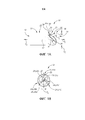
фиг.1А представляет собой схематический вид сбоку концевой фрезы в соответствии с предметом настоящей заявки, включающий в себя вид профиля вершины в верхнем правом углу;FIG. 1A is a schematic side view of an end mill in accordance with the subject matter of this application, including a top profile view in the upper right corner;
фиг.1В представляет собой схематический вид с переднего торца концевой фрезы по фиг.1А;FIG. 1B is a schematic front end view of the end mill of FIG. 1A; FIG.
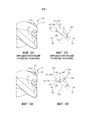
фиг.2А представляет собой схематический вид сбоку участка режущей части концевой фрезы по предшествующему уровню техники (слегка повернутый в направлении резания относительно вида профиля);FIG. 2A is a schematic side view of a portion of the cutting portion of an end mill according to the prior art (slightly turned in the cutting direction relative to the profile view);
фиг.2В представляет собой схематический увеличенный вид окруженной части, обозначенной IIВ на фиг.2А;FIG. 2B is a schematic enlarged view of the surrounded part, labeled IIB in FIG. 2A;
фиг.3А представляет собой вид, аналогичный фиг.2А, в частности, схематический вид сбоку участка режущей части концевой фрезы по фиг.1А и 1В (слегка повернутый в направлении резания относительно вида профиля по фиг.1А);Fig. 3A is a view similar to Fig. 2A, in particular, a schematic side view of a portion of the cutting portion of the end mill of Fig. 1A and 1B (slightly rotated in the cutting direction relative to the profile view of Fig. 1A);
фиг.3В представляет собой схематический увеличенный вид окруженной части, обозначенной IIIВ на фиг.3А;FIG. 3B is a schematic enlarged view of the surrounded portion, labeled IIIB in FIG. 3A;
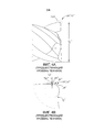
фиг.4А показывает вид сбоку участка режущей части концевой фрезы по предшествующему уровню техники (включающий в себя вид профиля вершины в верхнем правом углу);figa shows a side view of a section of the cutting part of the end mill according to the prior art (including the top profile view in the upper right corner);
фиг.4В представляет собой схематический увеличенный вид окруженной части, обозначенной IVВ на фиг.4А;FIG. 4B is a schematic enlarged view of the surrounded portion, designated IVB in FIG. 4A;
фиг.5А представляет собой схематический вид профиля вершины режущей части концевой фрезы по предшествующему уровню техники;figa is a schematic view of the profile of the top of the cutting part of the end mill according to the prior art;
фиг.5В представляет собой схематический увеличенный вид окруженной части, обозначенной VВ на фиг.5А;FIG. 5B is a schematic enlarged view of the surrounded portion, designated VB in FIG. 5A;
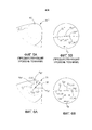
фиг.6А представляет собой схематический вид профиля вершины режущей части концевой фрезы по фиг.1А, 1В, 3А и 3В; иfiga is a schematic view of the profile of the apex of the cutting part of the end mill of figa 1A, 1B, 3A and 3B; and
фиг.6В представляет собой схематический увеличенный вид окруженной части, обозначенной VIВ на фиг.6А.FIG. 6B is a schematic enlarged view of the surrounded portion designated VIB in FIG. 6A.
ПОДРОБНОЕ ОПИСАНИЕ ИЗОБРЕТЕНИЯDETAILED DESCRIPTION OF THE INVENTION
[0021] Рассматриваются фиг.1А и 1В, которые иллюстрируют концевую фрезу 10, как правило, изготовленную из чрезвычайно твердого и износостойкого материала, такого как твердый сплав, и, в частности, выполненную с конфигурацией для чистовых операций механической обработки.[0021] FIGS. 1A and 1B are considered which illustrate an
[0022] Концевая фреза 10 выполнена с конфигурацией, обеспечивающей возможность ее вращения вокруг оси 12 вращения, которая может проходить в продольном направлении через ее центр и совпадать с центром СР1 концевой фрезы. В данном примере направление DA вращения концевой фрезы представляет собой направление против часовой стрелки на виде с переднего торца, показанном на фиг.1В. Ось 12 вращения может определять направление DF вперед и противоположное направление DR назад (следует отметить, что, несмотря на то, что данные направления параллельны оси 12 вращения, они необязательно должны быть коаксиальными с ней).[0022]
[0023] Концевая фреза 10 может содержать передний конец 14, задний конец 16, расположенный дистально по отношению к переднему концу 14, и периферийную поверхность 18, продолжающуюся между передним и задним концами 14, 16.[0023] The
[0024] Концевая фреза 10 может содержать режущую часть 20 и хвостовую часть 22, расположенную сзади от режущей части 20.[0024] the
[0025] Режущая часть 20 может иметь диаметр DC режущей части и может проходить назад от переднего конца 14.[0025] The cutting
[0026] Режущая часть 20 может содержать, по меньшей мере, один зуб 24 (например, первый, второй и третий зубья 24А, 24В, 24С).[0026] The cutting
[0027] Каждый зуб 24 может быть гладким (то есть нерифленым) для улучшенной чистовой обработки обрабатываемой детали.[0027] Each tooth 24 may be smooth (i.e., non-grooved) for improved finishing of the workpiece.
[0028] Режущая часть 20 может содержать стружечную канавки 26, расположенную в направлении вдоль окружности между соседними зубьями 24 (например, стружечная канавка 26А может быть расположена в направлении вдоль окружности между первым и вторым зубьями 24А, 24В). Режущая часть 20 может содержать множество стружечных канавок 26 (например, первую, вторую и третью стружечные канавки 26А, 26В, 26С). Каждая стружечная канавка 26 может иметь угол Н наклона/подъема винтовой линии (например, постоянный или переменный), образованный относительно оси 12 вращения.[0028] The cutting
[0029] Как также показано на фиг.3В, каждый зуб 24 может содержать переднюю поверхность 28; выпуклую радиальную заднюю поверхность 30; режущую кромку 32, образованную на пересечении передней поверхности 28, и выпуклой радиальной задней поверхности 30, и заднюю поверхность 34 вершины, соединенную с передней поверхностью 28 и с выпуклой радиальной задней поверхностью 30.[0029] As also shown in FIG. 3B, each tooth 24 may include a
[0030] Выпуклая радиальная задняя поверхность 30 может содержать выпуклую часть 30а, непосредственно смежную режущей кромке 32, и плоскую часть 30b, отделенную от режущей кромки 32 выпуклой частью 30а.[0030] The convex
[0031] Хотя предмет настоящей заявки и не ограничен этим, он рассматривается как особенно предпочтительный для выпуклой радиальной задней поверхности и имеющей такую конструкцию с выпуклой и плоской частями 30а, 30b.[0031] Although the subject matter of the present application is not limited to this, it is considered as particularly preferable for a convex radial back surface and having such a construction with convex and
[0032] Каждый зуб 24 может проходить от переднего конца 14 до периферийной поверхности 18.[0032] Each tooth 24 may extend from the
[0033] На пересечении переднего конца 14 и периферийной поверхности 18 каждый зуб 24 может содержать вершину 36.[0033] At the intersection of the
[0034] На виде профиля, показанном на фиг.1А, во время вращения концевой фрезы 10 вокруг оси 12 вращения вершина 36 имеет профиль 38 с формой дуги окружности, образующий часть воображаемой окружности IC.[0034] In the profile view shown in FIG. 1A, during rotation of the
[0035] Привлекая внимание к фиг.6А, следует отметить, что окружность IC может иметь центр СР2 окружности, аксиальную и радиальную тангенциальные линии LAT, LRT, точки РАТ, РRT прохождения аксиальной и радиальной тангенциальных линий и величину М радиуса, измеряемую от центра СР2 окружности до профиля 38 с формой дуги окружности.[0035] Drawing attention to Fig. 6A, it should be noted that the circle I C may have a center C P2 of a circle, axial and radial tangential lines L AT , L RT , points P AT , P RT passing axial and radial tangential lines and the value M radius, measured from the center of the C P2 circle to the
[0036] Точка РАТ прохождения аксиальной тангенциальной линии расположена на пересечении окружности IC и аксиальной тангенциальной линии LAT, продолжающейся вперед от центра СР2 окружности и в направлении, параллельном оси 12 вращения концевой фрезы 10. Точка РRТ прохождения радиальной тангенциальной линии расположена на пересечении окружности IC и радиальной тангенциальной линии LRT, продолжающейся от центра СР2 окружности и в радиальном направлении наружу перпендикулярно к оси 12 вращения. Радиальная тангенциальная плоскость SRT образована перпендикулярно к оси 12 вращения и включает в себя радиальную тангенциальную линию LRT. Другими словами, радиальная тангенциальная плоскость SRT может быть определена как плоскость, проходящая перпендикулярно к оси 12 вращения и включающая в себя как центр СР2 окружности, так и точку РRТ прохождения радиальной тангенциальной линии. Радиальная тангенциальная плоскость SRT расположена на расстоянии от точки РАТ прохождения аксиальной тангенциальной линии, равном величине М радиуса.[0036] Point P AT at the passage of the axial tangential line is located at the intersection of the circumference IC and the axial tangential line L AT , extending forward from the center C P2 of the circle and in a direction parallel to the
[0037] В сущности говоря, после определения места расположения центра окружности (или, более точно, аксиального расстояния между центром окружности и точкой прохождения аксиальной тангенциальной линии, которое также будет равно величине радиуса) (например, во время вращения концевой фрезы и осмотра вида профиля, такого как вид, показанный на фиг.6А), может быть установлено положение радиальной тангенциальной плоскости, которая представляет собой плоскость, перпендикулярную к оси вращения концевой фрезы, и в которой лежит центр окружности. После определения места расположения радиальной тангенциальной плоскости концевая фреза может быть приведена во вращение вокруг оси вращения, и могут быть определены другие элементы/характеристики, такие как протяженность задней поверхности вершины относительно положения радиальной тангенциальной плоскости.[0037] In essence, after determining the location of the center of the circle (or, more precisely, the axial distance between the center of the circle and the point of passage of the axial tangential line, which will also be equal to the radius) (for example, during rotation of the end mill and inspection of the profile view , such as the view shown in FIG. 6A), the position of the radial tangential plane, which is a plane perpendicular to the axis of rotation of the end mill, and in which the center of the circle lies, can be established. After determining the location of the radial tangential plane, the end mill can be rotated around the axis of rotation, and other elements / characteristics can be determined, such as the length of the rear surface of the tip relative to the position of the radial tangential plane.
[0038] Привлекая внимание к фиг.2А и 2В, следует отметить, что режущая часть 20ʹ концевой фрезы по предшествующему уровню техники показана в целях сравнения, при этом соответствующие элементы имеют такие же ссылочные позиции, к которым также добавлен апостроф (').[0038] Drawing attention to FIGS. 2A and 2B, it should be noted that the cutting
[0039] В частности, самая задняя точка 34аʹ задней поверхности вершины которая представляет собой заднюю поверхность 34ʹ вершины по предшествующему уровню техники расположена спереди от радиальной тангенциальной плоскости SRTʹ. Напротив, задняя поверхность 34 вершины на фиг.3А и 3В проходит сзади от радиальной тангенциальной плоскости SRT.[0039] In particular, the rearmost point 34aʹ of the rear surface of the top, which is the
[0040] Сзади от радиальной тангенциальной плоскости SRT задняя поверхность 34 вершины вблизи самой задней точки 34а задней поверхности вершины которая представляет собой заднюю поверхность 34 вершины может иметь форму 40 края задней поверхности вершины. Как показано, форма 40 края может быть сужающейся. Форма края 40 задней поверхности вершины может рассматриваться как треугольная.[0040] Behind the radial tangential plane S RT, the
[0041] Самая задняя точка 34а задней поверхности вершины расположена спереди от задней крайней радиальной плоскости SRE. Заднее аксиальное расстояние LRA, определяемое между радиальной тангенциальной плоскостью SRT и задней крайней радиальной плоскостью SRE, может быть равно 5% или менее от величины М радиуса (фиг.6А).[0041] The
[0042] Привлекая внимание к фиг.4А и 4В, следует отметить, что режущая часть 20ʹʹ концевой фрезы по предшествующему уровню техники показана в целях сравнения, при этом соответствующие элементы имеют такие же ссылочные позиции, к которым также добавлены два апострофа (ʹʹ), и ко всем остальным ссылочным позициям на данных фигурах также добавлены два апострофа (ʹʹ).[0042] Drawing attention to FIGS. 4A and 4B, it should be noted that the cutting part 20ʹʹ of the end mill of the prior art is shown for comparison purposes, with the corresponding elements having the same reference numbers, to which two apostrophes (ʹʹ) are also added, and to all other reference numbers in these figures, two apostrophes (ʹʹ) are also added.
[0043] В частности, профиль 38ʹʹ с формой дуги окружности перестает следовать вдоль окружности ICʹʹ в точке разрыва непрерывности, обозначенной 44ʹʹ. Следовательно, имеется радиальный зазор 46ʹʹ между точкой PRTʹʹ прохождения радиальной тангенциальной линии, которая расположена на окружности ICʹʹ, и концевой фрезой 10ʹʹ. Радиальный зазор 46ʹʹ может иметь радиальную длину LRʹʹ, измеряемую от точки PRTʹʹ прохождения радиальной тангенциальной линии до концевой фрезы 10ʹʹ в направлении, перпендикулярном к оси 12 вращения.[0043] In particular, the profile 38ʹʹ with the shape of an arc of a circle ceases to follow along the circle I C ʹʹ at the point of discontinuity, denoted 44. Therefore, there is a radial gap 46ʹʹ between the point P RT ʹʹ of the radial tangential line, which is located on the circumference I C , and the
[0044] Напротив, как показано на фиг.6А, профиль 38 с формой дуги окружности следует вдоль окружности IC, и радиальная длина LR (непоказанная) составляет не более 0,04% от диаметра DC режущей части (фиг.1А). В показанном примере радиальная длина LR не показана, поскольку она настолько мала, что ее невозможно увидеть.[0044] In contrast, as shown in Fig. 6A, a profile with a circular arc shape follows a circumference I C , and the radial length L R (not shown) is no more than 0.04% of the diameter D C of the cutting part (Fig. 1A) . In the example shown, the radial length L R is not shown, since it is so small that it cannot be seen.
[0045] Привлекая внимание к фиг.5А и 5В, следует отметить, что режущая часть концевой фрезы по предшествующему уровню техники показана в целях сравнения, при этом соответствующие элементы имеют такие же ссылочные позиции, к которым также добавлены три апострофа (ʹʹʹ).[0045] Drawing attention to FIGS. 5A and 5B, it should be noted that the cutting portion of an end mill according to the prior art is shown for comparison purposes, with the corresponding elements having the same reference numbers, to which also three apostrophes (ʹʹʹ) are added.
[0046] На фиг.5В показана точка 33ʹʹʹ соединения, в которой задняя поверхность 34ʹʹʹ вершины соединена с криволинейной радиальной задней поверхностью 30ʹʹʹ у режущей кромки 32ʹʹʹ. В частности, задняя поверхность 34ʹʹʹ вершины соединена нетангенциально с радиальной задней поверхностью 30ʹʹʹ у режущей кромки 32ʹʹʹ на значительном расстоянии от точки РRTʹʹʹ прохождения радиальной тангенциальной линии спереди от нее. Следовательно, траектории радиальной задней поверхности 30ʹʹʹ и окружности ICʹʹʹ расходятся сзади от точки 33ʹʹʹ соединения.[0046] FIG. 5B shows a connection point 33ʹʹʹ, in which the top back surface 34ʹʹʹ is connected to a curved
[0047] Напротив, фиг.6В показывает точку 33 соединения, в которой задняя поверхность 34 вершины соединена с радиальной задней поверхностью 30 у режущей кромки 32. Точка 33 соединения может находиться спереди от радиальной тангенциальной плоскости SRT, но должна, тем не менее, находиться сзади от передней крайней радиальной плоскости SFE (которая представляет собой плоскость, параллельную радиальной тангенциальной плоскости SRT). Передняя крайняя радиальная плоскость SFE расположена спереди от радиальной тангенциальной плоскости SRT не дальше от нее, чем на переднем аксиальном расстоянии LFA, равном 5% от величины М радиуса (фиг.6А). Наиболее предпочтительно, как показано, если тангенциальное соединение находится в точке РRT прохождения радиальной тангенциальной линии. Кроме того, задняя поверхность 34 вершины тангенциально соединена с радиальной задней поверхностью 30 у режущей кромки 32.[0047] In contrast, FIG. 6B shows a
[0048] Как показано, траектории радиальной задней поверхности 30 и окружности IC выровнены сзади от радиальной тангенциальной плоскости SRT.[0048] As shown, the trajectories of the
[0049] Вышеприведенное описание включает в себя приведенный в качестве примера вариант осуществления и детали и не исключает не приведенных в качестве примера вариантов осуществления и деталей из объема формулы изобретения по настоящей заявке.[0049] The above description includes an exemplary embodiment and details, and does not exclude embodiments and details not exemplified in the scope of the claims of the present application.
Claims (24)
Applications Claiming Priority (3)
| Application Number | Priority Date | Filing Date | Title |
|---|---|---|---|
| US14/486,118 US9517515B2 (en) | 2014-09-15 | 2014-09-15 | End mill convex radial relief surface and corner having circular arc profile |
| US14/486,118 | 2014-09-15 | ||
| PCT/IL2015/050810 WO2016042542A1 (en) | 2014-09-15 | 2015-08-09 | End mill with convex radial relief surface and corner having circular arc profile |
Publications (3)
| Publication Number | Publication Date |
|---|---|
| RU2017112927A RU2017112927A (en) | 2018-10-17 |
| RU2017112927A3 RU2017112927A3 (en) | 2019-02-04 |
| RU2693971C2 true RU2693971C2 (en) | 2019-07-08 |
Family
ID=54541130
Family Applications (1)
| Application Number | Title | Priority Date | Filing Date |
|---|---|---|---|
| RU2017112927A RU2693971C2 (en) | 2014-09-15 | 2015-08-09 | End mill with convex radial rear surface and corner having circular arc profile |
Country Status (12)
| Country | Link |
|---|---|
| US (1) | US9517515B2 (en) |
| EP (1) | EP3194101B1 (en) |
| JP (1) | JP6709788B2 (en) |
| KR (1) | KR102350910B1 (en) |
| CN (1) | CN106687240B (en) |
| CA (1) | CA2959773C (en) |
| ES (1) | ES2951080T3 (en) |
| IL (1) | IL250252A0 (en) |
| PL (1) | PL3194101T3 (en) |
| PT (1) | PT3194101T (en) |
| RU (1) | RU2693971C2 (en) |
| WO (1) | WO2016042542A1 (en) |
Families Citing this family (13)
| Publication number | Priority date | Publication date | Assignee | Title |
|---|---|---|---|---|
| WO2013175478A2 (en) | 2012-05-24 | 2013-11-28 | Gershon System Ltd. | Method for designing a cutting edge of a cutting tool, cutting tools comprising the same, and cutting elements with multiple such cutting portions |
| EP3046708A1 (en) * | 2013-09-17 | 2016-07-27 | Gershon System Ltd. | Cutting element and a method of cutting using the same |
| US10040136B2 (en) | 2015-10-12 | 2018-08-07 | Iscar, Ltd. | End mill having teeth and associated flutes with correlated physical parameters |
| US10131003B2 (en) * | 2015-11-23 | 2018-11-20 | Iscar, Ltd. | Cemented carbide corner radius end mill with continuously curved rake ridge and helical flute design |
| EP3479941A4 (en) * | 2016-06-30 | 2020-04-01 | NGK Spark Plug Co., Ltd. | Endmill body and radius end mill |
| US9884379B1 (en) | 2017-03-07 | 2018-02-06 | Iscar, Ltd. | Ceramic face mill with circular arc profile for machining Inconel |
| US11351619B2 (en) * | 2017-03-13 | 2022-06-07 | Moldino Tool Engineering, Ltd. | Ball end mill |
| IL257313B (en) | 2018-02-01 | 2022-01-01 | Hanita Metal Works Ltd | Multi-flute end mill |
| US10486246B2 (en) | 2018-02-26 | 2019-11-26 | Iscar, Ltd. | End mill having a peripheral cutting edge with a variable angle configuration |
| JP7075584B2 (en) * | 2018-04-16 | 2022-05-26 | 三菱重工業株式会社 | Radius end mills, machine tools using them, and design methods and processing methods for radius end mills. |
| WO2020033168A1 (en) * | 2018-08-09 | 2020-02-13 | Kyocera Sgs Precision Tools, Inc. | Variable radius gash |
| EP3865237A4 (en) | 2018-10-11 | 2022-07-13 | MOLDINO Tool Engineering, Ltd. | End mill |
| IL264757B (en) | 2019-02-10 | 2022-07-01 | Hanita Metal Works Ltd | End mill with independent rake surfaces |
Citations (6)
| Publication number | Priority date | Publication date | Assignee | Title |
|---|---|---|---|---|
| SU1183307A1 (en) * | 1983-07-12 | 1985-10-07 | Предприятие П/Я А-1264 | Cutting tool |
| RU2147492C1 (en) * | 1998-07-06 | 2000-04-20 | Алтайский государственный технический университет им.И.И.Ползунова | End milling cutter |
| EP1348508A1 (en) * | 2002-03-25 | 2003-10-01 | Hitachi Tool Engineering Ltd. | Radius end mill having radius edge enhanced in resistance to chipping and fracture |
| RU2392095C1 (en) * | 2009-05-25 | 2010-06-20 | Нина Алексеевна Корюкина | End milling cutter |
| RU125502U1 (en) * | 2012-07-19 | 2013-03-10 | Черкашин Валентин Павлович | ENHANCED END MILL |
| WO2014076691A1 (en) * | 2012-11-14 | 2014-05-22 | Iscar Ltd. | Corner radius end mill |
Family Cites Families (19)
| Publication number | Priority date | Publication date | Assignee | Title |
|---|---|---|---|---|
| JP3335401B2 (en) * | 1993-01-20 | 2002-10-15 | 日進工具株式会社 | End mill |
| JP2003071625A (en) * | 2001-08-30 | 2003-03-12 | Hitachi Tool Engineering Ltd | End mill |
| JP2003275918A (en) * | 2002-03-25 | 2003-09-30 | Hitachi Tool Engineering Ltd | High feed cutting radius end mill |
| JP4540292B2 (en) * | 2002-10-22 | 2010-09-08 | オーエスジー株式会社 | Radius end mill |
| US6991409B2 (en) | 2002-12-24 | 2006-01-31 | Niagara Cutter | Rotary cutting tool |
| CN100522433C (en) * | 2002-12-26 | 2009-08-05 | 三菱麻铁里亚尔株式会社 | Radius end mill |
| DE20310713U1 (en) * | 2003-07-12 | 2003-09-18 | Fette Gmbh | end mill |
| US20050105973A1 (en) * | 2003-11-18 | 2005-05-19 | Robbjack Corporation | Variable flute helical-pitch rotary cutting tool |
| JP2005297107A (en) * | 2004-04-09 | 2005-10-27 | Nachi Fujikoshi Corp | Radius end mill |
| JP2005319558A (en) * | 2004-05-11 | 2005-11-17 | Hitachi Tool Engineering Ltd | Cutting edge replaceable-type finishing radius end mill |
| US7699565B2 (en) * | 2005-03-28 | 2010-04-20 | Osg Corporation | Radius endmill |
| JP2007030074A (en) * | 2005-07-25 | 2007-02-08 | Mitsubishi Materials Kobe Tools Corp | Radius end mill and cutting method |
| DE102006026853A1 (en) * | 2006-06-09 | 2007-12-13 | Franken GmbH + Co KG Fabrik für Präzisionswerkzeuge | Machining tool |
| JP5194680B2 (en) * | 2006-10-06 | 2013-05-08 | 三菱マテリアル株式会社 | Radius end mill |
| FR2926480B1 (en) | 2008-01-23 | 2011-08-12 | Snecma | SURFACING AND CURVING MILL FOR HIGH-SPEED MACHINING OF COMPOSITE MATERIALS |
| JPWO2009123189A1 (en) * | 2008-03-31 | 2011-07-28 | 三菱マテリアル株式会社 | Radius end mill and cutting insert |
| JP5731102B2 (en) * | 2009-01-21 | 2015-06-10 | 三菱マテリアル株式会社 | Radius end mill |
| EP2722121B1 (en) * | 2011-06-17 | 2017-10-11 | Hitachi Tool Engineering, Ltd. | Multi-edge endmill |
| US20140356081A1 (en) * | 2013-05-30 | 2014-12-04 | Kennametal Inc. | End mill with high ramp angle capability |
-
2014
- 2014-09-15 US US14/486,118 patent/US9517515B2/en active Active
-
2015
- 2015-08-09 EP EP15794311.9A patent/EP3194101B1/en active Active
- 2015-08-09 CA CA2959773A patent/CA2959773C/en active Active
- 2015-08-09 WO PCT/IL2015/050810 patent/WO2016042542A1/en active Application Filing
- 2015-08-09 PT PT157943119T patent/PT3194101T/en unknown
- 2015-08-09 JP JP2017534022A patent/JP6709788B2/en active Active
- 2015-08-09 ES ES15794311T patent/ES2951080T3/en active Active
- 2015-08-09 RU RU2017112927A patent/RU2693971C2/en active
- 2015-08-09 PL PL15794311.9T patent/PL3194101T3/en unknown
- 2015-08-09 KR KR1020177006363A patent/KR102350910B1/en active IP Right Grant
- 2015-08-09 CN CN201580049500.7A patent/CN106687240B/en active Active
-
2017
- 2017-01-24 IL IL250252A patent/IL250252A0/en active IP Right Grant
Patent Citations (6)
| Publication number | Priority date | Publication date | Assignee | Title |
|---|---|---|---|---|
| SU1183307A1 (en) * | 1983-07-12 | 1985-10-07 | Предприятие П/Я А-1264 | Cutting tool |
| RU2147492C1 (en) * | 1998-07-06 | 2000-04-20 | Алтайский государственный технический университет им.И.И.Ползунова | End milling cutter |
| EP1348508A1 (en) * | 2002-03-25 | 2003-10-01 | Hitachi Tool Engineering Ltd. | Radius end mill having radius edge enhanced in resistance to chipping and fracture |
| RU2392095C1 (en) * | 2009-05-25 | 2010-06-20 | Нина Алексеевна Корюкина | End milling cutter |
| RU125502U1 (en) * | 2012-07-19 | 2013-03-10 | Черкашин Валентин Павлович | ENHANCED END MILL |
| WO2014076691A1 (en) * | 2012-11-14 | 2014-05-22 | Iscar Ltd. | Corner radius end mill |
Also Published As
| Publication number | Publication date |
|---|---|
| US9517515B2 (en) | 2016-12-13 |
| WO2016042542A1 (en) | 2016-03-24 |
| RU2017112927A (en) | 2018-10-17 |
| EP3194101B1 (en) | 2023-07-26 |
| EP3194101A1 (en) | 2017-07-26 |
| BR112017004439A2 (en) | 2017-12-05 |
| CA2959773C (en) | 2022-08-30 |
| ES2951080T3 (en) | 2023-10-17 |
| KR20170054396A (en) | 2017-05-17 |
| JP6709788B2 (en) | 2020-06-17 |
| US20160074947A1 (en) | 2016-03-17 |
| PL3194101T3 (en) | 2023-08-28 |
| CN106687240A (en) | 2017-05-17 |
| RU2017112927A3 (en) | 2019-02-04 |
| PT3194101T (en) | 2023-08-01 |
| IL250252A0 (en) | 2017-03-30 |
| JP2017526548A (en) | 2017-09-14 |
| CA2959773A1 (en) | 2016-03-24 |
| CN106687240B (en) | 2019-11-26 |
| KR102350910B1 (en) | 2022-01-13 |
Similar Documents
| Publication | Publication Date | Title |
|---|---|---|
| RU2693971C2 (en) | End mill with convex radial rear surface and corner having circular arc profile | |
| CN106687239B (en) | Double-sided cutting insert and milling tool | |
| RU2635681C2 (en) | End milling cutter with angular radius | |
| US9364904B2 (en) | Variable lead end mill | |
| JP5687705B2 (en) | Twist drill | |
| JP2011500350A (en) | Cutting tool | |
| JP2013521899A (en) | Drill bit | |
| KR102532903B1 (en) | Cemented carbide corner radius end mill with continuously curved bevel ridges and helical flutes | |
| KR102465176B1 (en) | Interchangeable cutting heads, tool holders and rotary cutting tools having a threaded mounting portion with two spaced apart conical adjacent surfaces provided with the same cone angle | |
| JP6361948B2 (en) | Cutting inserts and cutting tools | |
| KR20200063171A (en) | Square-shaped cutting inserts and rotary cutting tools with curved secondary and corner cutting edges | |
| KR102582310B1 (en) | Endmill with peripheral cutting edge with variable angle geometry | |
| JPWO2019188135A1 (en) | End mill body and end mill | |
| CN107000077B (en) | Ramping insert and high feed milling tool assembly | |
| CN109420790B (en) | Solid end mill with complex clearance surface | |
| CN109641292B (en) | Ramping insert and fast feed milling tool assembly | |
| JP6691441B2 (en) | End mill | |
| JP2019526464A (en) | Cutting tool with indexable cutting insert held by moment force around pivot axis | |
| JP6028841B2 (en) | Ball end mill | |
| BR112017004439B1 (en) | END MILL |