RU2682498C2 - Locker system for electrolyser - Google Patents
Locker system for electrolyser Download PDFInfo
- Publication number
- RU2682498C2 RU2682498C2 RU2016134372A RU2016134372A RU2682498C2 RU 2682498 C2 RU2682498 C2 RU 2682498C2 RU 2016134372 A RU2016134372 A RU 2016134372A RU 2016134372 A RU2016134372 A RU 2016134372A RU 2682498 C2 RU2682498 C2 RU 2682498C2
- Authority
- RU
- Russia
- Prior art keywords
- covers
- plugs
- plug
- cover
- cell
- Prior art date
Links
Images

Classifications
-
- C—CHEMISTRY; METALLURGY
- C25—ELECTROLYTIC OR ELECTROPHORETIC PROCESSES; APPARATUS THEREFOR
- C25C—PROCESSES FOR THE ELECTROLYTIC PRODUCTION, RECOVERY OR REFINING OF METALS; APPARATUS THEREFOR
- C25C3/00—Electrolytic production, recovery or refining of metals by electrolysis of melts
- C25C3/06—Electrolytic production, recovery or refining of metals by electrolysis of melts of aluminium
- C25C3/22—Collecting emitted gases
-
- C—CHEMISTRY; METALLURGY
- C25—ELECTROLYTIC OR ELECTROPHORETIC PROCESSES; APPARATUS THEREFOR
- C25C—PROCESSES FOR THE ELECTROLYTIC PRODUCTION, RECOVERY OR REFINING OF METALS; APPARATUS THEREFOR
- C25C3/00—Electrolytic production, recovery or refining of metals by electrolysis of melts
- C25C3/06—Electrolytic production, recovery or refining of metals by electrolysis of melts of aluminium
- C25C3/08—Cell construction, e.g. bottoms, walls, cathodes
Landscapes
- Chemical & Material Sciences (AREA)
- Engineering & Computer Science (AREA)
- Chemical Kinetics & Catalysis (AREA)
- Electrochemistry (AREA)
- Materials Engineering (AREA)
- Metallurgy (AREA)
- Organic Chemistry (AREA)
- Electrolytic Production Of Metals (AREA)
- Electrolytic Production Of Non-Metals, Compounds, Apparatuses Therefor (AREA)
Abstract
Description
Настоящее изобретение относится к запорной системе для электролизера, к электролизеру, содержащему эту запорную систему, и к способу замены анодного устройства.The present invention relates to a locking system for an electrolyzer, to an electrolyzer containing this locking system, and to a method for replacing an anode device.
Обычно алюминий производят на алюминиевых заводах путем электролиза при помощи способа Холла-Эру.Typically, aluminum is produced in aluminum smelters by electrolysis using the Hall-Heroux method.
Алюминиевый завод обычно содержит несколько сот последовательно соединенных в ряд электролизеров, через которые проходит электролизный ток, сила которого может достигать нескольких сот тысяч ампер. Как известно, электролизеры расположены поперечно по отношению к направлению прохождения электролизного тока в масштабах одного ряда.An aluminum smelter usually contains several hundred cells connected in series to a series of electrolyzers through which an electrolysis current passes, the strength of which can reach several hundred thousand amperes. As is known, electrolyzers are located transversely with respect to the direction of passage of the electrolysis current on the scale of one row.
Классически электролизеры содержат стальной кожух, внутри которого выполнена футеровка из огнеупорных материалов, катод из углеродистого материала, через который проходят катодные шины, предназначенные для сбора электролизного тока на катоде и для его передачи на катодные выводы, проходящие через дно или стороны кожуха, передаточные шины, проходящие по существу горизонтально от катодных выводов до следующего электролизера, электролитическую ванну, в которой растворен глинозем, по меньшей мере одно анодные устройство, содержащее по меньшей мере один анод, погруженный в эту электролитическую ванну, и анодную штангу, закрепленную в аноде, анодную раму, на которой подвешивают анодное устройство через анодную штангу, и шины подвода электролизного тока, проходящие снизу вверх и соединенные с передаточными шинами предыдущего электролизера для передачи электролизного тока от катодных выводов на анодную раму и на анодное устройство и анод следующего электролизера. В частности, аноды являются предварительно обожженными анодами с предварительно обожженными углеродистыми блоками, то есть, блоками, обожженными до введения в электролизер.Classically, electrolyzers contain a steel casing, inside of which a lining is made of refractory materials, a cathode of carbon material, through which cathode buses are used to collect electrolysis current at the cathode and to transfer it to the cathode terminals passing through the bottom or sides of the casing, transfer tires, extending essentially horizontally from the cathode leads to the next electrolyzer, an electrolytic bath in which alumina is dissolved, at least one anode device containing at least one anode immersed in this electrolytic bath and an anode rod fixed in the anode, an anode frame on which the anode device is suspended through the anode rod, and electrolysis current supply buses passing from the bottom up and connected to the transmission buses of the previous electrolysis cell for transmitting the electrolysis cell current from the cathode terminals to the anode frame and to the anode device and the anode of the next cell. In particular, the anodes are pre-fired anodes with pre-fired carbon blocks, that is, blocks fired before being introduced into the cell.
В ходе реакции электролиза анодные устройства расходуются, поэтому их необходимо регулярно заменять новыми анодными устройствами.During the electrolysis reaction, the anode devices are consumed, so they must be regularly replaced with new anode devices.
Стороны электролизера ограничивают проем, через который анодные устройства вводят в электролизер и погружают в электролитическую ванну или извлекают из электролизера для замены.The sides of the cell limit the opening through which the anode devices are introduced into the cell and immersed in the electrolytic bath or removed from the cell for replacement.
Чтобы ограничивать тепловые потери и избегать распространения за пределы электролизера газов, выделяющихся во время реакции электролиза и в дальнейшем называемых электролизными газами, предусмотрено закрывание проема, ограниченного электролизером, при помощи запорной системы. Известные запорные системы, раскрытые в патентных документах US4043892 и WO2007067061, содержат съемные боковые крышки, наклоненные относительно горизонтали. Эти крышки опираются, во-первых, на одну из сторон электролизера и, во-вторых, на часть надстройки, предназначенной для удержания анодных устройств и расположенной в продольном направлении электролизера над проемом, ограниченным боковыми сторонами электролизера, то есть над анодными устройствами и электролитической ванной.In order to limit the heat loss and to avoid the spread of the gases emitted during the electrolysis reaction and hereinafter referred to as electrolysis gases, it is provided that the opening limited by the electrolyzer be closed with a locking system. Known locking systems disclosed in patent documents US4043892 and WO2007067061 contain removable side covers that are inclined relative to the horizontal. These covers are based, firstly, on one of the sides of the cell and, secondly, on the part of the superstructure designed to hold the anode devices and located in the longitudinal direction of the cell over the opening bounded by the sides of the cell, that is, over the anode devices and the electrolytic bath .
Таким образом, крышки образуют изолирующее ограждение, ограничивающее распространение электролизных газов, когда система закрывания полностью закрыта. Это позволяет ограничить также тепловые потери.Thus, the covers form an insulating fence that limits the spread of electrolysis gases when the closing system is completely closed. This also limits the heat loss.
Однако во время вмешательства, требующего открывания запорной системы, как в случае замены отработанного анодного устройства новым анодным устройством, традиционные запорные системы лишь частично решают проблему распространения электролизных газов электролиза за пределы электролизера и поддержания термического равновесия электролизера.However, during an intervention requiring the opening of the locking system, as in the case of replacing the spent anode device with a new anode device, traditional locking systems only partially solve the problem of the spread of electrolysis electrolysis gases outside the cell and maintaining the thermal equilibrium of the cell.
Действительно, во время вмешательства, такого как замена анодного устройства, крышки снимают для получения проема в запорной системе. Этот необходимый проем позволяет получить доступ внутрь электролизера, в частности, для извлечения отработанного анодного устройства. Однако получаемый таким образом проем дает возможность электролизным газам выйти за пределы изолирующего ограждения. Этот проем может также нарушить термическое равновесие электролизера.Indeed, during an intervention, such as replacing the anode device, the covers are removed to obtain an opening in the locking system. This necessary opening allows access to the inside of the cell, in particular, to extract the spent anode device. However, the opening thus obtained allows electrolysis gases to go beyond the insulating enclosure. This opening may also upset the thermal balance of the cell.
Чем больше создаваемый проем, тем большее количество электролизных газов может выйти наружу и тем больше происходит тепловых потерь. Это же касается продолжительности открывания запорной системы во время вмешательства: чем дольше запорная система остается открытой, тем большее количество электролизных газов может выйти наружу и тем больше нарушается термическое равновесие электролизера.The larger the opening created, the greater the amount of electrolysis gases can go outside and the more heat loss occurs. The same applies to the duration of the opening of the locking system during the intervention: the longer the locking system remains open, the greater the number of electrolysis gases can go outside and the more the thermal equilibrium of the electrolyzer is disturbed.
Учитывая присутствие над кожухом надстройки, на которую опираются крышки известных запорных систем, крышки, которые были сняты для создания проема, необходимого для вмешательства, часто располагают рядом с электролизером, в частности, в промежуточном пространстве, разделяющем два смежных электролизера. Это может создать проблему загромождения, которая может замедлить вмешательство, то есть увеличить время, в течение которого запорная система остается открытой. Кроме того, это может создать проблему безопасности, поскольку оператор может споткнуться об эти крышки.Given the presence above the casing of the superstructure on which the lids of the known locking systems rest, the lids that were removed to create the opening required for intervention are often placed next to the cell, in particular in the intermediate space separating two adjacent cells. This can create a clutter problem that can slow down the intervention, i.e. increase the time that the locking system remains open. In addition, this can create a safety problem, as the operator may trip over these covers.
Кроме того, крышки известных запорных систем выполнены таким образом, что их смежные края располагаются друг над другом. Это расположение друг над другом позволяет ограничить утечки электролизных газов и энергетические потери в промежутке между двумя смежными крышками.In addition, the lids of the known locking systems are designed so that their adjacent edges are located one above the other. This arrangement one above the other allows to limit leakage of electrolysis gases and energy losses in the gap between two adjacent covers.
Однако традиционные решения наложения друг на друга крышек имеют недостаток: крышки перекрывают друг друга, и извлечение одной из них требует перемещения или извлечения одной или нескольких смежных крышек. Таким образом, понятно, что при операции обслуживания, теоретически требующей снятия только одной крышки, необходимо переместить или снять несколько крышек. Следовательно, площадь, открываемая через запорную систему, является большей, чем это необходимо. В патентных документах US4043892 и WO2007067061 описано снятие крышек группами по три штуки.However, traditional solutions of overlapping covers have a disadvantage: the covers overlap each other, and removing one of them requires moving or removing one or more adjacent covers. Thus, it is understood that in a maintenance operation that theoretically requires only one cover to be removed, several covers must be moved or removed. Therefore, the area opened through the locking system is larger than necessary. In patent documents US4043892 and WO2007067061 describes the removal of covers in groups of three.
Наконец, некоторые операции обслуживания могут потребовать меньших открытых площадей, чем при других операциях обслуживания. Например, чтобы разбить корку, образующуюся на электролитической ванне во время реакции электролиза, достаточно отверстия, позволяющего ввести в надлежащем месте инструмент, предназначенный для разбивания корки, тогда как для извлечения или установки на место анодного устройства необходим больший проем, соответствующий размерам извлекаемого или устанавливаемого на место анодного устройства.Finally, some maintenance operations may require less open space than other maintenance operations. For example, to break the crust formed on the electrolytic bath during the electrolysis reaction, a hole is enough to allow a tool to break in the crust to be inserted in the proper place, while a larger opening corresponding to the dimensions of the removed or installed on place of the anode device.
Однако крышки традиционных запорных систем являются подобными, в частности, с точки зрения размеров, поэтому единственной возможностью выбора площади проема в запорной системе является выбор числа снимаемых крышек. Это не позволяет точно подбирать площадь проема, то есть выбрать минимальную площадь проема, вместе с тем достаточную для осуществления необходимой операции обслуживания.However, the covers of traditional locking systems are similar, in particular in terms of size, therefore, the only way to select the opening area in the locking system is to select the number of covers to be removed. This does not allow you to accurately select the opening area, that is, to select the minimum opening area, however, sufficient to carry out the necessary maintenance operation.
Кроме того, присутствие надстройки и шин, подводящих электролизный ток, над проемом, ограниченным боковыми сторонами электролизера, затрудняют операцию пробивания корки, образующейся между анодными устройствами, так как доступ под надстройкой и токоподводящими шинами является исключительно ограниченным. Вследствие этого операция пробивания корки, обычно выполняемая при помощи отбойного молотка, установленного на штанге с угловым наклоном, требует больше времени, чем если бы таких препятствий не было, что приводит к увеличению продолжительности открывания запорной системы. Кроме того, учитывая эту проблему доступа, пробивание корки иногда оказывается неполным на периферии анодного устройства, и извлекаемое анодное устройство содержит твердые куски корки, которые увеличивают его проходное сечение, его габарит и могут повредить остающиеся на месте смежные крышки.In addition, the presence of a superstructure and buses supplying electrolysis current over an opening bounded by the sides of the electrolyzer makes it difficult to pierce the crust formed between the anode devices, since access under the superstructure and current-carrying tires is extremely limited. As a result of this, the crust punching operation, usually performed with a jackhammer mounted on an angularly inclined rod, requires more time than if there were no such obstacles, which leads to an increase in the duration of opening of the locking system. In addition, given this access problem, the piercing of the crust is sometimes incomplete at the periphery of the anode device, and the removable anode device contains solid pieces of the crust that increase its cross section, its size and may damage the remaining adjacent covers.
Наконец, своей нижней частью крышки опираются на верхнюю часть кожуха, на которой оседает вещество покрытия анодов, поэтому опоры крышек являются неустойчивыми, и их позиционирование - не совсем точным. Кроме того, в своей нижней части они подвергаются действию пламени и горячих точек, связанных с прерывистостью анодного покрытия, что приводит к их быстрому износу.Finally, with their lower part, the covers rest on the upper part of the casing, on which the coating material of the anodes settles, so the supports of the covers are unstable, and their positioning is not entirely accurate. In addition, in their lower part they are exposed to flame and hot spots associated with the discontinuity of the anode coating, which leads to their rapid wear.
Задачей настоящего изобретения является устранение вышеуказанных недостатков и разработка запорной системыу, электролизера, содержащего эту запорную систему, и способа замены анодного устройства, которые позволяет эффективно сдерживать распространение электролизных газов и сохранять термическое равновесие, в частности, во время операции обслуживания.The objective of the present invention is to eliminate the above disadvantages and to develop a locking system, an electrolyzer containing this locking system, and a method for replacing an anode device that can effectively inhibit the spread of electrolysis gases and maintain thermal equilibrium, in particular, during a maintenance operation.
В связи с этим объектом изобретения является запорная система, предназначенная для закрывания проема, ограниченного боковыми сторонами электролизера, при этом запорная система содержит множество крышек, отличающаяся тем, что:In this regard, the object of the invention is a locking system designed to close an opening bounded by the sides of the electrolyzer, while the locking system contains many lids, characterized in that:
- каждая крышка содержит два противоположных опорных края, опирающихся на две противоположные боковые стороны электролизера среди боковых сторон электролизера, ограничивающих проем, при этом каждая крышка расположена от одной боковой стороны к другой боковой стороне электролизера над проемом,- each lid contains two opposite supporting edges resting on two opposite sides of the cell among the sides of the cell defining the opening, each cover being located from one side to the other side of the cell above the opening,
- запорная система выполнена таким образом, что по существу параллельно крышкам содержит продольные смотровые окна, позволяющие освободить заранее определенный проход через множество крышек,- the locking system is designed in such a way that essentially parallel to the covers contains longitudinal viewing windows, allowing you to clear a predetermined passage through many covers,
- запорная система дополнительно содержит заглушки, при этом каждая заглушка является подвижной относительно крышек между закрытым положением, в котором каждая заглушка закрывает одно из смотровых окон, и рабочим положением, в котором каждая заглушка освобождает проход в запорной системе через одно из смотровых окон, при этом заглушки выполнены таким образом, что по меньшей мере частично опираются на крышки, и- the locking system further comprises plugs, wherein each plug is movable relative to the covers between a closed position in which each plug closes one of the viewing windows and a working position in which each plug releases a passage in the locking system through one of the viewing windows, wherein the plugs are designed in such a way that at least partially rest on the covers, and
- заглушки выполнены с возможностью перемещения из закрытого положения в рабочее положение независимо друг от друга без перемещения крышек, на которые опираются заглушки.- the caps are made with the possibility of moving from the closed position to the working position independently from each other without moving the covers on which the caps are based.
Таким образом, заявленная запорная система обеспечивает возможность доступа внутрь электролизера за счет снятия только одной из заглушек без перемещения или снятия крышек.Thus, the claimed locking system provides access to the inside of the cell by removing only one of the plugs without moving or removing the covers.
Это позволяет получать проем ограниченного размера в запорной системе, оставляя крышки на месте. В рамках вмешательства, такого как замена анодного устройства, это позволяет осуществлять некоторые предварительные операции, такие как срезание корок, образовавшихся вокруг анодного устройства, отработанного во время реакции электролиза, при минимальной открытой площади в запорной системе.This allows you to get a limited size opening in the locking system, leaving the covers in place. As part of an intervention, such as replacing the anode device, this allows for some preliminary operations, such as cutting the crusts formed around the anode device spent during the electrolysis reaction, with a minimum open area in the shut-off system.
Это ограничивает выбросы электролизных газов наружу электролизера и предупреждает нарушение термического равновесия электролизера.This limits the emission of electrolysis gases to the outside of the cell and prevents the violation of the thermal equilibrium of the cell.
Под противоположными боковыми сторонами электролизера следует понимать боковые стороны, расположенные с двух сторон от центральной плоскости, в частности, от продольной центральной плоскости электролизера. Таким образом, каждая крышка располагается по обе стороны от этой центральной плоскости, опираясь одновременно на эти две противоположные боковые стороны.Opposite lateral sides of the electrolyzer should be understood as the lateral sides located on two sides of the central plane, in particular, from the longitudinal central plane of the electrolyzer. Thus, each cover is located on both sides of this central plane, resting simultaneously on these two opposite side sides.
Крышки и заглушки имеют вертикальный ход соединения, что является существенным преимуществом для автоматизации установки крышек на место, так как в отличие от известных решений нет необходимости в сложных угловых движениях.Lids and caps have a vertical connection stroke, which is a significant advantage for automating the installation of covers in place, since, in contrast to known solutions, there is no need for complex angular movements.
Согласно предпочтительному варианту выполнения, заглушки имеют продольные края, каждый из которых опирается на одну из крышек. Таким образом, герметичность соединения между заглушками и крышками обеспечивается по всей длине крышек, соответственно заглушек, за счет расположения края заглушки над краем крышки.According to a preferred embodiment, the plugs have longitudinal edges, each of which rests on one of the covers. Thus, the tightness of the connection between the plugs and caps is ensured along the entire length of the caps, respectively caps, due to the location of the edge of the cap over the edge of the cap.
Согласно предпочтительному варианту выполнения, заглушки имеют поперечное сечение в виде Т, ограничивающее два продольных загиба, крышки имеют поперечное сечение в виде перевернутого Т, ограничивающее два продольных загиба, при этом каждый загиб одной из заглушек опирается на один из загибов смежной крышки, при этом запорная система содержит чередование посаженных друг на друга крышек и заглушек.According to a preferred embodiment, the plugs have a cross section in the form of T, limiting two longitudinal bends, the covers have a cross section in the form of an inverted T, limiting two longitudinal bends, while each bend of one of the plugs rests on one of the bends of the adjacent cover, while the system comprises alternating lids and plugs stacked on top of each other.
Эта конфигурация одновременно обеспечивает простое решение для снятия заглушек без помех со стороны крышек, на которые опираются они и другие заглушки, и для улучшения герметичности запорной системы. Это позволяет ограничить утечки электролизных газов и тепловые потери.This configuration at the same time provides a simple solution for removing the plugs without interference from the covers on which they rest and other plugs, and to improve the tightness of the locking system. This limits the leakage of electrolysis gases and heat loss.
Предпочтительно загибы крышек и заглушек имеют сечение в виде L таким образом, что соединение путем посадки между крышкой и заглушкой образует герметизирующую перегородку.Preferably, the bends of the covers and plugs have a section in the form of L in such a way that the connection by means of a fit between the cover and the plug forms a sealing wall.
Этот признак обеспечивает улучшенную герметичность и позволяет ограничить утечки электролизных газов и тепловые потери.This feature provides improved tightness and limits leakage of electrolysis gases and heat loss.
Предпочтительно запорная система содержит уплотнительные средства, расположенные между загибами каждой заглушки и загибами смежных крышек, на которые опирается каждая заглушка.Preferably, the locking system comprises sealing means located between the bends of each cap and the bends of adjacent covers on which each cap rests.
Это позволяет улучшить герметичность.This improves the tightness.
Согласно предпочтительному варианту выполнения, крышки и заглушки расположены горизонтально, и продольные загибы крышек образуют желоба, содержащие порошкообразный материал и имеющие верхний проем, при этом продольные загибы крышек имеют сечение в виде L таким образом, что концевой участок сечения в виде L заглушки погружается в порошкообразный материал через верхний проем в желоб при соединении посадкой друг на друга крышки и заглушки. Выполнение такой уплотнительной прокладки при помощи порошкообразного материала стало возможным, так как крышки и заглушки расположены горизонтально, и порошкообразный материал остается распределенным с равномерной высотой по всей длине желоба. Порошкообразный материал образует барьер, не пропускающий электролизные газы.According to a preferred embodiment, the covers and plugs are arranged horizontally, and the longitudinal folds of the covers form grooves containing a powdery material and having an upper opening, while the longitudinal folds of the covers have a cross section in the form of L so that the end section of the cross section in the form of an L plug is immersed in powder the material through the upper opening into the chute when connected by landing on top of each other lids and plugs. The implementation of such a sealing gasket using a powder material has become possible, since the covers and plugs are horizontal and the powder material remains distributed with a uniform height along the entire length of the gutter. Powdered material forms a barrier that does not allow electrolysis gases to pass through.
Предпочтительно порошкообразный материал содержит глинозем. В частности, порошкообразный материал может представлять собой глинозем или измельченную корку электролизной ванны, которая содержит глинозем. Преимуществом этих материалов является их постоянное наличие в алюминиевом цеху, и, кроме того, их вводят в электролизеры без риска загрязнения электролизера в случае случайного высыпания в ванну. Кроме того, глинозем является очень хорошим абсорбентом для HF и SO2, выходящих из электролизера, поэтому возможная инфильтрация электролизных газов через порошкообразный материал будет иметь меньшие последствия для окружающей среды.Preferably, the particulate material contains alumina. In particular, the powdered material may be alumina or a crushed crust of an electrolysis bath that contains alumina. The advantage of these materials is their constant presence in the aluminum workshop, and, in addition, they are introduced into the cells without the risk of contamination of the cell in case of accidental pouring into the bath. In addition, alumina is a very good absorbent for HF and SO2 exiting the electrolyzer, so possible infiltration of electrolysis gases through the powder material will have less environmental impact.
Предпочтительно крышки и/или заглушки содержат щиток, выполненный с возможностью закрывания проема желоба, когда крышку и заглушку соединяют путем посадки друг на друга. Этот щиток, который может быть неподвижным или подвижным, в частности, поворотным, предназначен для удержания порошкообразного материала в желобе.Preferably, the lids and / or plugs comprise a flap configured to close the opening of the trough when the lid and plug are connected by landing on each other. This flap, which can be fixed or movable, in particular rotary, is designed to hold the powdered material in the gutter.
Согласно предпочтительному варианту выполнения, уплотнительные средства содержат эластичные уплотнительные прокладки, предназначенные для компенсации разности относительной деформации между двумя последовательными крышками запорной системы, между которыми располагается заглушка в закрытом положении.According to a preferred embodiment, the sealing means comprise elastic gaskets designed to compensate for the difference in relative deformation between two successive closures of the locking system, between which the plug is located in the closed position.
Иначе говоря, размеры пространства или зазора между крышками и заглушками рассчитаны таким образом, чтобы с учетом прогиба крышек и заглушек сдавливание разделяющих их уплотнительных прокладок находилось в диапазоне упругого сдавливания уплотнительных прокладок. Это позволяет улучшить герметичность.In other words, the dimensions of the space or gap between the caps and plugs are designed so that, taking into account the deflection of the caps and plugs, the compression of the sealing gaskets separating them is in the range of elastic compression of the sealing gaskets. This improves the tightness.
Согласно предпочтительному варианту выполнения, крышки содержат сторону, оснащенную по меньшей мере одной усилительной нервюрой, предназначенной для ограничения прогиба крышек.According to a preferred embodiment, the covers comprise a side equipped with at least one reinforcing rib designed to limit the deflection of the covers.
Это позволяет повысить жесткость крышек. Таким образом, сдавливание уплотнительных прокладок является относительно равномерным. Это позволяет улучшить герметичность.This allows you to increase the rigidity of the covers. Thus, the compression of the gaskets is relatively uniform. This improves the tightness.
Согласно предпочтительному варианту выполнения, крышки содержат сторону, оснащенную средствами теплоизоляции.According to a preferred embodiment, the covers comprise a side equipped with heat insulation means.
Это позволяет ограничить тепловые потери через запорную систему.This allows you to limit heat loss through the locking system.
Предпочтительно средства изоляции расположены на нижней стороне крышек, чтобы ограничить коробление и, следовательно, износ крышек.Preferably, the insulation means are located on the underside of the covers in order to limit warpage and therefore wear of the covers.
Предпочтительно крышки содержат по существу продольный трубчатый корпус, при этом трубчатый корпус ограничивает полость, внутри которой находится теплоизоляционный материал.Preferably, the covers comprise a substantially longitudinal tubular body, the tubular body defining a cavity within which the insulating material is located.
Эти признаки позволяют предохранить теплоизоляционный материал и ограничить тепловые потери за счет синергического эффекта между теплоизоляционным материалом, который замедляет распространение тепла через запорную систему, и повышенной жесткостью крышек за счет трубчатого выполнения корпуса, причем эта жесткость обеспечивает равномерную опору крышки на поверхность, на которой она установлена, и равномерную опору заглушек, которые опираются на эту крышку.These features make it possible to protect the heat-insulating material and limit heat losses due to the synergistic effect between the heat-insulating material, which slows down the distribution of heat through the locking system, and the increased stiffness of the covers due to the tubular execution of the housing, and this rigidity provides uniform support of the cover on the surface on which it is installed , and even support for the plugs that rest on this cover.
Согласно предпочтительному варианту выполнения, крышки содержат нижнюю сторону, оснащенную отклоняющими средствами, предназначенными для отклонения потока электролизных газов.According to a preferred embodiment, the covers comprise a bottom side equipped with deflecting means for deflecting the flow of electrolysis gases.
Это позволяет отклонять электролизные газы в направлении системы улавливания, которой может быть оснащен электролизер, и ограничить утечки электролизных газов.This allows you to deflect the electrolysis gases in the direction of the capture system, which can be equipped with an electrolyzer, and limit leakage of electrolysis gases.
Согласно предпочтительному варианту выполнения, заглушки содержат захватные средства, позволяющие поднимать по существу вертикально каждую заглушку, не перемещая крышки и независимо от других заглушек.According to a preferred embodiment, the plugs comprise gripping means allowing each plug to be lifted substantially vertically without moving the covers and independently of the other plugs.
По существу вертикальное снятие заглушек ограничивает риск перемещения смежных крышек во время снятия и представляет собой самое простое решение для применения системы уплотнения между заглушками и смежными с ними крышками.The substantially vertical removal of the plugs limits the risk of moving adjacent caps during removal and is the simplest solution for applying a sealing system between the caps and their caps.
Согласно предпочтительному варианту выполнения, заглушки содержат нижнюю опорную сторону, позволяющую заглушкам устойчиво опираться на одну из крышек или на другую заглушку.According to a preferred embodiment, the plugs comprise a lower support side, allowing the plugs to stably support one of the covers or the other plug.
Таким образом, снятые заглушки можно уложить штабелем на смежную крышку или на другую ближайшую заглушку. Следовательно, траектории, которые описывает сервисная электролизная машина во время вмешательства, являются минимальными, поэтому продолжительность открывания смотрового окна тоже является минимальной. Это позволяет уменьшить утечки электролизных газов и тепловые потери во время вмешательства.Thus, the removed plugs can be stacked on an adjacent cover or other closest plug. Therefore, the trajectories described by the service electrolysis machine during the intervention are minimal, therefore, the duration of opening the inspection window is also minimal. This reduces the leakage of electrolysis gases and heat loss during the intervention.
Согласно предпочтительному варианту выполнения, крышки содержат нижнюю опорную сторону, позволяющую крышкам устойчиво опираться на заглушки.According to a preferred embodiment, the covers comprise a lower abutment side allowing the covers to stably support the caps.
Таким образом, снятые крышки можно уложить штабелем на смежную крышку или на ближайшую заглушку. За счет этого траектории сервисной электролизной машины во время вмешательства уменьшаются, и, как следствие, уменьшается продолжительность открывания смотрового окна. Это позволяет уменьшить утечки электролизных газов и тепловые потери во время вмешательства, в частности, во время замены анодного устройства.Thus, removed covers can be stacked on an adjacent cover or on the closest cover. Due to this, the trajectories of the service electrolysis machine during the intervention are reduced, and, as a result, the duration of opening the viewing window is reduced. This allows to reduce leakage of electrolysis gases and heat loss during the intervention, in particular, during the replacement of the anode device.
Согласно предпочтительному варианту выполнения, крышки и заглушки расположены по существу в горизонтальной плоскости.According to a preferred embodiment, the covers and plugs are located essentially in a horizontal plane.
Это позволяет быстро укладывать их штабелем во время вмешательства, уменьшить продолжительность этого вмешательства и, следовательно, продолжительность открывания запорной системы.This allows you to quickly stack them in a stack during the intervention, to reduce the duration of this intervention and, therefore, the duration of the opening of the locking system.
Предпочтительно смотровое окно имеет ширину, меньшую ширины крышек, разделенных этим смотровым окном.Preferably, the inspection window has a width smaller than the width of the covers separated by this inspection window.
Эта незначительная площадь открывания запорной системы позволяет создать, в сочетании с традиционным всасыванием электролизных газов, эффект всасывания наружного воздуха внутрь электролизера, противодействующий движению электролизных газов. За счет этого уменьшаются утечки электролизных газов.This small opening area of the locking system allows you to create, in combination with the traditional absorption of electrolysis gases, the effect of absorption of external air into the cell, counteracting the movement of electrolysis gases. Due to this, leakage of electrolysis gases is reduced.
Каждая заглушка имеет ширину, меньшую ширины крышек.Each cap has a width less than the width of the covers.
Предпочтительно крышки имеют жесткость при прогибе, превышающую жесткость при прогибе заглушек.Preferably, the covers have a flexural rigidity greater than that of the plugs.
Иначе говоря, крышки деформируются в меньшей степени, чем заглушки, и заглушки деформируются легче, чем крышки, под действием своего веса, поэтому заглушки могут деформироваться, чтобы компенсировать меньшие деформации крышек, на которые они опираются. Это позволяет улучшить герметичность.In other words, the caps are deformed to a lesser extent than the caps, and the caps are deformed more easily than the caps due to their weight, therefore, the caps can be deformed to compensate for the smaller deformations of the caps on which they rest. This improves the tightness.
Объектом настоящего изобретения является также электролизер, содержащий множество анодных устройств, боковые стороны, ограничивающие проем, через который устанавливают на место или извлекают анодные устройства соответственно опускающимся или поднимающимся поступательным движением, при этом над анодными устройствами выполнена запорная система, закрывающая упомянутый проем.An object of the present invention is also an electrolytic cell containing a plurality of anode devices, lateral sides defining an opening, through which the anode devices are inserted into place or removed with a corresponding lowering or rising translational movement, and a locking system is formed over the anode devices to close said opening.
Этот электролизер характеризуется стабильным термическим равновесием и ограничивает выбросы электролизных газов, в том числе во время вмешательства, такого как замена анодного устройства.This electrolyzer is characterized by stable thermal equilibrium and limits the emission of electrolysis gases, including during the intervention, such as the replacement of the anode device.
Согласно предпочтительному варианту выполнения, электролизер содержит уплотнительные средства, расположенные между опорными краями крышек и боковыми сторонами электролизера, на которые опираются опорные края.According to a preferred embodiment, the cell contains sealing means located between the supporting edges of the covers and the sides of the cell, on which the supporting edges are supported.
Это позволяет улучшить герметичность. Это препятствует также утечке электролизных газов и ограничивает тепловые потери.This improves the tightness. It also prevents leakage of electrolysis gases and limits heat loss.
Предпочтительно уплотнительные средства, расположенные между опорными краями крышек и боковыми сторонами электролизера, на которые опираются опорные края, содержат уплотнительную прокладку, и электролизер содержит средства сжатия уплотнительной прокладки.Preferably, the sealing means located between the supporting edges of the covers and the sides of the electrolyzer, on which the supporting edges are supported, comprise a sealing gasket, and the electrolyzer contains compression means for the sealing gasket.
Это позволяет корректировать возможные дефекты плоскостности крышек и, в случае необходимости, заглушек с целью ограничения утечек электролизных газов и тепловых потерь.This allows you to correct possible defects in the flatness of the covers and, if necessary, plugs in order to limit leakage of electrolysis gases and heat loss.
Согласно предпочтительному варианту выполнения, каждая заглушка расположена над и вдоль нижележащего промежуточного пространства между анодами, разделяющего два смежных анодных устройства электролизера.According to a preferred embodiment, each plug is located above and along the underlying intermediate space between the anodes, separating two adjacent anode electrolytic cells.
Это позволяет получать доступ над промежуточными поверхностями между анодами, поэтому операцию, такую как срезание корки, можно производить при минимальной открытой площади. Таким образом, эту операцию, предшествующую замене анодного устройства, осуществляют при минимальными утечках электролизных газов и тепловых потерях.This allows you to access above the intermediate surfaces between the anodes, so an operation, such as cutting the crust, can be performed with a minimum open area. Thus, this operation, preceding the replacement of the anode device, is carried out with minimal leakage of electrolysis gases and heat loss.
Под промежуточным пространством между анодами следует понимать пространство, разделяющее аноды двух смежных анодных устройств.The intermediate space between the anodes should be understood as the space separating the anodes of two adjacent anode devices.
Согласно предпочтительному варианту выполнения, каждая крышка расположена над и вдоль нижележащего анодного устройства электролизера.According to a preferred embodiment, each cover is located above and along the underlying anode device of the electrolyzer.
Таким образом, крышки необходимо снимать только в том случае, когда извлекают анодное устройство. Остальное время крышки могут оставаться на месте, препятствуя утечкам электролизных газов и ограничивая тепловые потери. Эта конфигурация позволяет также свести к минимуму риск падения в электролизер для обслуживающего персонала.Thus, covers should only be removed when the anode device is removed. The rest of the time, the covers can remain in place, preventing leakage of electrolysis gases and limiting heat loss. This configuration also minimizes the risk of dropping into the cell for maintenance personnel.
Согласно предпочтительному варианту выполнения, электролизер содержит установочные средства для установки крышек в заранее определенное положение крышек, в котором крышки расположены напротив анодных устройств.According to a preferred embodiment, the electrolyzer comprises installation means for installing the covers in a predetermined position of the covers, in which the covers are located opposite the anode devices.
Этот признак обеспечивает быструю, повторяемую и точную установку на место крышек для быстрого закрывания проема и препятствуют смещению этих крышек.This feature provides quick, repeatable, and accurate installation of covers in place to quickly close the opening and prevent displacement of these covers.
Под выражением «крышки расположены напротив анодных устройств» следует понимать, что под каждой крышкой находится только одно анодное устройство.The expression "covers are located opposite the anode devices" it should be understood that under each cover there is only one anode device.
Согласно предпочтительному варианту выполнения, электролизер содержит средства улавливания электролизных газов, выполненные с возможностью улавливания и сбора электролизных газов, выделяющихся во время реакции электролиза.According to a preferred embodiment, the electrolyzer comprises electrolysis gas trapping means configured to trap and collect electrolysis gases released during the electrolysis reaction.
Это ограничивает количество электролизных газов, которое может выйти через проем при открывании запорной системы.This limits the amount of electrolysis gases that can escape through the opening when the shut-off system is opened.
Предпочтительно средства улавливания содержат отверстия всасывания, выполненные под крышками и заглушками.Preferably, the collection means comprises suction openings formed under covers and plugs.
Это позволяет ограничить температуру воздуха вблизи крышек и заглушек, чтобы избежать ухудшения механической прочности материалов, из которых выполнены крышки и заглушки. Это ограничивает деформации крышек и заглушек, поскольку эти деформации могут способствовать утечкам электролизных газов и тепловым потерям.This allows you to limit the air temperature near the covers and plugs in order to avoid deterioration of the mechanical strength of the materials of which the caps and plugs are made. This limits the deformation of the covers and plugs, as these deformations can contribute to leakage of electrolysis gases and heat loss.
За счет взаимодействия с отклоняющими средствами, выполненными на нижней стороне крышек и предназначенными для отклонения потока газов, это позволяет улучшить КПД улавливания электролизера.Due to the interaction with deflecting means, made on the underside of the covers and designed to deflect the gas flow, this improves the efficiency of capture of the cell.
Предпочтительно средства улавливания содержат диафрагму, предназначенную для изменения проходного воздушного сечения с целью изменения расхода улавливания электролизных газов.Preferably, the capture means comprise a diaphragm designed to change the air passage in order to change the capture rate of electrolysis gases.
Этот признак позволяет увеличить расход улавливания, когда снимают крышку и/или заглушку, например, во время замены анодного устройства. Таким образом, распространение электролизных газов во время вмешательства существенно ограничено.This feature allows you to increase the capture rate when you remove the cover and / or plug, for example, when replacing the anode device. Thus, the distribution of electrolysis gases during the intervention is significantly limited.
Согласно предпочтительному варианту выполнения, ширина каждой крышки меньше ширины анодного устройства электролизера.According to a preferred embodiment, the width of each cover is less than the width of the anode device of the electrolyzer.
Еще одним объектом изобретения является способ замены отработанного анодного устройства электролизера на новое анодное устройство, при этом способ содержит:Another object of the invention is a method for replacing the spent anode device of the electrolyzer with a new anode device, the method comprising:
- этап перемещения первой заглушки среди заглушек запорной системы, имеющей вышеупомянутые признаки, из закрытого положения в рабочее положение, не перемещая крышки запорной системы и другие заглушки, чтобы освободить проход в запорной системе через одно из смотровых окон, и- the step of moving the first plug among the plugs of the locking system having the aforementioned features from the closed position to the working position without moving the covers of the locking system and other plugs to clear the passage in the locking system through one of the viewing windows, and
- этап разбивания или срезания корки, образовавшейся на поверхности электролитической ванны, путем введения инструмента, выполненного с возможностью разбивания или срезания корки, через проход, освобожденный на предыдущем этапе.- the step of breaking or cutting the crust formed on the surface of the electrolytic bath by introducing a tool configured to break or cut the crust through the passage freed in the previous step.
Этот способ позволяет получить доступ внутрь электролизера при минимальной площади проема и, следовательно, разбивать или срезать корку, образовавшуюся во время реакции электролиза, при минимальных утечках электролизных газов и тепловых потерях. Таким образом, во время замены анодного устройства распространение электролизных газов и тепловые потери оказываются значительно ограниченными.This method allows access to the inside of the cell with a minimum opening area and, therefore, to break or cut off the crust formed during the electrolysis reaction, with minimal leakage of electrolysis gases and heat loss. Thus, during the replacement of the anode device, the propagation of electrolysis gases and heat losses are significantly limited.
Согласно предпочтительному варианту осуществления, способ содержит этап укладки первой заглушки на одну из крышек, смежных с первой заглушкой.According to a preferred embodiment, the method comprises the step of laying the first plug on one of the covers adjacent to the first plug.
Это позволяет свести к минимуму траектории сервисной электролизной машины, когда она манипулирует первой заглушкой. Продолжительность вмешательства оказывается ограниченной, и, следовательно, ограничивается продолжительность открывания смотрового окна.This minimizes the trajectory of the service electrolysis machine when it manipulates the first plug. The duration of the intervention is limited, and, therefore, the duration of the opening of the viewing window is limited.
Согласно предпочтительному варианту осуществления, способ содержит этап перемещения второй заглушки из закрытого положения в рабочее положение без перемещения крышек запорной системы и других заглушек, при этом вторую заглушку располагают с другой стороны одной из крышек, рядом с которыми находится первая заглушка, чтобы освободить второй проход с другой стороны этой крышки, и этап разбивания или срезания корки, образовавшейся на поверхности электролитической ванны, путем введения инструмента, выполненного с возможностью разбивания или срезания корки, через этот второй проход.According to a preferred embodiment, the method comprises the step of moving the second plug from the closed position to the working position without moving the covers of the locking system and other plugs, the second plug being placed on the other side of one of the covers next to which the first plug is in order to free the second passage from the other side of this cover, and the step of breaking or cutting the crust formed on the surface of the electrolytic bath by introducing a tool made with the possibility of breaking or peeling, through this second passage.
Это позволяет перед заменой анодного устройства срезать, разбить или пробить корку с двух сторон от отработанного анодного устройства, которое необходимо заменить, то есть с двух сторон от крышки, первоначально расположенной между первой и второй заглушками, но не открывая при этом все пространство над этим отработанным анодным устройством. Следовательно, во время замены анодного устройств утечки электролизных газов и тепловые потери оказываются ограниченными.This allows, before replacing the anode device, to cut, break or pierce the crust on both sides of the spent anode device, which must be replaced, that is, on both sides of the cover, originally located between the first and second plugs, but without opening all the space above this used anode device. Consequently, during the replacement of the anode devices, leakage of electrolysis gases and heat loss are limited.
Согласно предпочтительному варианту осуществления, способ содержит этап укладки второй заглушки на первую заглушку.According to a preferred embodiment, the method comprises the step of laying the second plug on the first plug.
Укладка штабелем заглушек позволяет ограничить пути сервисной электролизной машины и, следовательно, время, в течение которого остаются открытыми соответствующие смотровые окна.Stacking the plugs allows you to limit the path of the service electrolysis machine and, therefore, the time during which the corresponding inspection windows remain open.
Согласно предпочтительному варианту осуществления, способ содержит этап снятия крышки, первоначально смежной с первой заглушкой.According to a preferred embodiment, the method comprises the step of removing the lid initially adjacent to the first plug.
Таким образом, одну из крышек снимают только в последний момент, то есть в момент захвата и подъема отработанного анодного устройства для его замены. Во время всех предварительных этапов, необходимых для замены анодного устройства, эта крышка остается на месте. Таким образом, заявленный способ позволяет ограничить утечки электролизных газов и сохранять термическое равновесие электролизера во время замены анодного устройства.Thus, one of the covers is removed only at the last moment, that is, at the time of gripping and lifting the spent anode device to replace it. During all the preliminary steps necessary to replace the anode device, this cover remains in place. Thus, the claimed method allows to limit leakage of electrolysis gases and maintain thermal equilibrium of the electrolyzer during the replacement of the anode device.
Предпочтительно способ содержит этап укладки штабелем упомянутой крышки на первую заглушку или, в случае необходимости, на вторую заглушку.Preferably, the method comprises the step of stacking said cover onto a first plug or, if necessary, a second plug.
Это позволяет уменьшить путь сервисной электролизной машины после снятия крышки, поэтому проем, полученный при снятии крышки и первой и второй заглушек для замены анодного устройства, остается открытым во время ограниченного времени.This allows you to reduce the path of the service electrolysis machine after removing the cover, so the opening obtained by removing the cover and the first and second plugs to replace the anode device remains open for a limited time.
После этого способ может содержать этап извлечения отработанного анодного устройства, находящегося под предварительно снятой крышкой, затем этап введения нового анодного устройства внутрь электролизера.After this, the method may include the step of extracting the spent anode device located under the previously removed cover, then the step of introducing a new anode device into the cell.
Эти этапы можно осуществлять путем по существу вертикального поднимающегося или опускающегося поступательного движения соответственно отработанного анодного устройства и нового анодного устройства.These steps can be carried out by essentially vertical rising or lowering translational motion of the spent anode device and a new anode device, respectively.
Наконец, способ может содержать этап обратной установки на место предварительно снятой крышки, затем первой и второй заглушек.Finally, the method may include the step of reinstalling the previously removed cover, then the first and second plugs.
Установка на место сначала крышки позволяет закрыть более значительную часть открытой поверхности, чем поверхность, которую можно было бы закрыть заглушкой.Replacing the cover first allows you to close a larger part of the open surface than a surface that could be closed with a plug.
Другие отличительные признаки и преимущества настоящего изобретения будут более очевидны из нижеследующего описания варианта его осуществления, представленного в качестве не ограничительного примера, со ссылками на прилагаемые чертежи, на которых:Other features and advantages of the present invention will be more apparent from the following description of an embodiment thereof, presented by way of non-limiting example, with reference to the accompanying drawings, in which:
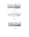
Фиг. 1 изображает схематичный вид в разрезе электролизера и запорной системы согласно варианту осуществления изобретения.FIG. 1 is a schematic sectional view of an electrolyzer and a shut-off system according to an embodiment of the invention.
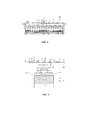
Фиг. 2 - схематичный вид сверху внутреннего пространства электролизера, показанного на фиг. 1.FIG. 2 is a schematic top view of the interior of the electrolyzer shown in FIG. one.
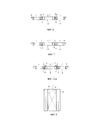
Фиг. 3 и 4 изображают схематичные виды в разрезе электролизера и запорной системы, показанных на фиг. 1, по существу в продольной плоскости электролизера, в которой выполнено смотровое окно.FIG. 3 and 4 are schematic sectional views of the electrolyzer and the locking system shown in FIG. 1, essentially in the longitudinal plane of the cell, in which a viewing window is formed.
Фиг. 5-7 - схематичные виды сбоку части запорной системы согласно варианту осуществления изобретения.FIG. 5-7 are schematic side views of a part of a locking system according to an embodiment of the invention.
Фиг. 7bis изображает схематичный вид сбоку части запорной системы согласно варианту осуществления изобретения.FIG. 7bis is a schematic side view of part of a locking system according to an embodiment of the invention.
Фиг. 8 - схематичный вид снизу крышки запорной системы согласно варианту осуществления изобретения.FIG. 8 is a schematic bottom view of a closure of a closure system according to an embodiment of the invention.
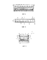
Фиг. 9 - схематичный вид в разрезе электролизера и запорной системы согласно варианту осуществления изобретения по существу в продольной плоскости электролизера.FIG. 9 is a schematic sectional view of an electrolyzer and a locking system according to an embodiment of the invention substantially in the longitudinal plane of the electrolyzer.
Фиг. 10 - схематичный вид сверху электролизера, показанного на фиг. 9.FIG. 10 is a schematic top view of the electrolyzer shown in FIG. 9.
Фиг. 11 - схематичный вид в разрезе электролизера и запорной системы согласно варианту осуществления изобретения по существу в поперечной плоскости электролизера.FIG. 11 is a schematic sectional view of an electrolyzer and a locking system according to an embodiment of the invention substantially in the transverse plane of the electrolyzer.
Фиг. 12-14 изображают схематичные виды в разрезе электролизера и запорной системы согласно варианту осуществления изобретения, иллюстрирующие различные этапы способа замены анодного устройства согласно варианту осуществления изобретения.FIG. 12-14 are schematic sectional views of an electrolyzer and a locking system according to an embodiment of the invention, illustrating the various steps of a method for replacing an anode device according to an embodiment of the invention.
На фиг. 1 показаны электролизер 100 согласно варианту выполнения изобретения, предназначенный для электролизного производства алюминия, и запорная система 1, предназначенная для закрывания проема электролизера.In FIG. 1 shows an
Электролизер 100 может входить в состав оборудования электролизного цеха, такого как цех алюминиевого завода. Электролизный цех может содержать множество электролизеров 100, расположенных в линию и электрически соединенных друг с другом, образуя ряд электролизеров. Через электролизеры 100 должен проходить электролизный ток, который может достигать нескольких сот тысяч ампер. Электролизеры 100 могут быть расположены поперечно относительно направления ряда, то есть по существу перпендикулярно к общему направлению прохождения электролизного тока в масштабе ряда.The
Как видно на фигурах, электролизер 100 может содержать две противоположные боковые стороны 101, которые могут быть по существу параллельными между собой, и две противоположные поперечные боковые стороны 103, которые могут быть по существу параллельными между собой и перпендикулярными к продольным боковым сторонам 101, поэтому электролизер 100 может иметь по существу прямоугольную форму.As can be seen in the figures, the
Электролизер 100 содержит неподвижную конструкцию. Неподвижная конструкция содержит кожух 102 и/или боковую стенку 105 изолирующего газы ограждения.The
Кожух 102 может содержать дно 104 из огнеупорных материалов, множество катодных блоков 106 и шины 1008 сбора электролизного тока, проходящего через катодные блоки 106.The
Электролизер 100 содержит также множество анодных устройств 109, которые являются подвижными и могут перемещаться по существу вертикальным поступательным движением относительно неподвижной конструкции электролизера для погружения в электролитическую ванну 110 по мере их расходования.The
В данном случае анодные устройства 109 содержат множество углеродистых блоков 112, закрепленных на электропроводящей анодной поперечине 114. Предпочтительно анодная поперечина 114 расположена по существу в поперечном направлении Y электролизера по существу в горизонтальной плоскости. Концы этой поперечины 114 электрически соединены с передаточными шинами (не показаны), обеспечивающими доставку электролизного тока от предыдущего электролизера.In this case, the
Боковые стороны электролизера 100 ограничивают проем 116, предназначенный для введения или извлечения анодных устройств 109 соответственно внутрь или наружу электролизера 100.The sides of the
Следует отметить, что этот проем 166 выполнен с возможностью обеспечения этого введения или этого извлечения путем по существу вертикального соответственно опускающего или поднимающегося перемещения анодного устройства 109.It should be noted that this opening 166 is configured to provide this introduction or this extraction by means of a substantially vertical respectively lowering or rising movement of the
В данном случае электролизер 100 содержит запорную систему 1. Запорная система 1 предназначена для закрывания проема 116, чтобы препятствовать распространению электролизных газов, выделяющихся во время реакции электролиза, за пределы электролизера 100. Запорная система 1 позволяет также ограничить тепловые потери.In this case, the
Как показано на фиг. 1, 3-5, 9 И 11-14, запорная система 1 расположена над анодными устройствами 109, полностью закрывая проем 116.As shown in FIG. 1, 3-5, 9, and 11-14, the
Запорная система 1 содержит множество крышек 2.The
Крышки 2 являются самонесущими. Каждая крышка 2 содержит два противоположных опорных края, показанных, в частности, на фиг. 11, предназначенных для опоры на две противоположные боковые стороны электролизера 100, в частности, на верхний край двух продольных боковых сторон 101 электролизера 100.
Таким образом, каждая крышка 2 полностью опирается на электролизер 100, располагаясь между двумя продольными боковыми сторонами 101 над проемом 116.Thus, each
Кроме того, запорная система 1 выполнена таким образом, что имеет продольные смотровые окна 6 по существу параллельно крышкам 2, как показано, например, на фиг. 4. Каждое смотровое окно 6 позволяет освободить заранее определенный проход через множество крышек 2.In addition, the
В варианте выполнения, показанном на фиг. 4, смотровые окна 6 расположены в продольном направлении между двумя смежными крышками 2.In the embodiment shown in FIG. 4, the
Запорная система 1 дополнительно содержит заглушки 8, каждая из которых предназначена для закрывания смотрового окна 6.The
Каждая заглушка 8 является подвижной относительно крышек 2 между закрытым положением, в котором каждая заглушка 6 закрывает одно из смотровых окон 8, и рабочим положением, в котором каждая заглушка освобождает проход в запорной системе 1 через смотровые окна 8.Each
Заглушки 8 по меньшей мере частично опираются на крышки 2, как показано, например, на фиг. 5.The
Заглушки 8 имеют продольные края, каждый из которых опирается на одну из крышек 2, и имеют боковые края, которые могут опираться на верхний край продольных боковых сторон 101 электролизера 100.The
Таким образом, заглушки 8 могут опираться сверху на две смежные крышки и располагаться между этими двумя смежными крышками 2.Thus, the
Необходимо отметить, что заглушки 8 выполнены с возможностью перемещения из закрытого положения в рабочее положение без перемещения крышек 2, на которые опираются заглушки 8.It should be noted that the
Кроме того, заглушки 8 можно перемещать из закрытого положения в рабочее положение независимо друг от друга, то есть таким образом, что перемещение одной из заглушек 8 не приводит к перемещению другой заглушки 8.In addition, the
Как показано на фигурах, крышки 2 и, в случае необходимости, заглушки 8 предпочтительно расположены в виде единого блока от одной продольной боковой стороны к другой электролизера 100.As shown in the figures, the
Крышки 2 и, в случае необходимости, заглушки 8 расположены по существу параллельно поперечному направлению Y электролизера 100.
Следует также отметить, что крышки 2 и заглушки 8 расположены по существу в горизонтальной плоскости. Предпочтительно крышки 2 и заглушки 8 расположены над рабочим полом, что ограничивает риск падения обслуживающего персонала в электролизер.It should also be noted that the
Следует отметить, что крышки 2 и заглушки 8 должны располагаться над электролитической ванной 110, температура которой может достигать примерно 1000°С. Следовательно, крышки 2 и заглушки 8 должны выдерживать температуру порядка нескольких сот градусов Цельсия без ущерба для их механических свойств и, в случае необходимости, их теплоизоляции.It should be noted that the
Как показано на фиг. 6 и 7, заглушки 8 имеют Т-образное поперечное сечение, ограничивающее два продольных загиба 10. Что касается крышек 2, то они имеют поперечное сечение в виде перевернутого Т, ограничивающее два продольных загиба 12.As shown in FIG. 6 and 7, the
Каждый загиб 10 одной из заглушек 8 опирается на один из загибов 12 смежной крышки 2.Each
Таким образом, запорная система 1 содержит чередование прямых Т и перевернутых Т, образованное чередованием посаженных друг на друга крышек 2 и заглушек 8.Thus, the
Кроме того, как показано на фиг. 7, загибы 10, 12 крышек 2 и заглушек 8 имеют сечение в виде L.Furthermore, as shown in FIG. 7, bends 10, 12 of
Таким образом, посадка друг на друга крышки 2 и заглушки 8 приводит к образованию герметизирующей перегородки.Thus, landing on each other of the
Предпочтительно запорная система 1 содержит также уплотнительные средства, расположенные между загибами 10 каждой заглушки 8 и загибами 12 смежных крышек 2.Preferably, the
Уплотнительные средства содержат, например, эластичные уплотнительные прокладки 14. Эластичные уплотнительные прокладки 14 предназначены для компенсации разности относительной деформации между двумя последовательными крышками 2, между которыми расположена заглушка 8.The sealing means contain, for example,
Как показано на фиг. 7bis, загибы 12 крышек содержат желоба, имеющие верхний проем и содержащие порошкообразный материал 31. Загибы 10 заглушек имеют L-образное сечение, и концевой участок L-образного сечения заглушки погружают в порошкообразный материал 31 через верхний проем в желобе, когда крышку и заглушку сажают друг на друга. Выполнение такой уплотнительной прокладки, представляющей собой порошкообразный материал, возможно, поскольку крышки и заглушки расположены горизонтально, поэтому порошкообразный материал остается распределенным с равномерной высотой по всей длине желоба. Порошкообразный материал служит уплотнительным средством, образуя барьер, не пропускающий электролизные газы.As shown in FIG. 7bis, the cover bends 12 comprise troughs having an upper opening and containing
В частности, порошкообразный материал может содержать глинозем или измельченную электролитическую ванну, которая содержит глинозем. Эти материалы имеются в наличии на алюминиевом заводе и, кроме того, при введении в электролизеры не рискуют загрязнить электролизер в случае случайного высыпания в электролизер. Кроме того, глинозем является хорошим абсорбентом для HF и SO2, выделяющихся в электролизере, поэтому возможная инфильтрация электролизных газов через порошкообразный материал будет иметь меньшие последствия для окружающей среды.In particular, the powdered material may contain alumina or a ground electrolytic bath that contains alumina. These materials are available at the aluminum smelter and, in addition, when introduced into the electrolytic cells, there is no risk of contaminating the electrolytic cell in the event of an accidental pouring into the electrolytic cell. In addition, alumina is a good absorbent for HF and SO2 released in the electrolyzer, so possible infiltration of electrolysis gases through the powder material will have less environmental impact.
Как показано на фиг. 7bis, крышка дополнительно содержит на своей верхней стороне поворотные щитки 32, выполненные с возможностью закрывания проема желоба, когда крышку и заглушку сажают друг на друга. Эти щитки должны удерживать порошкообразный материал в желобе. В альтернативном варианте щитки можно расположить на заглушке, и они могут быть неподвижными.As shown in FIG. 7bis, the lid further comprises on its upper side pivoting flaps 32 configured to close the opening of the trough when the lid and cap are pressed against each other. These shields must hold the powdery material in the gutter. Alternatively, the shields may be located on the plug and they may be stationary.
Крышки 2 имеют нижнюю сторону 16, показанную, в частности, на фиг. 8.The
Нижняя сторона 16 может содержать по меньшей мере одну усилительную нервюру 18, предназначенную для ограничения прогиба крышек 2. Согласно примеру, показанному на фиг. 8, крышки 2 могут содержать две перекрещивающиеся нервюры 18.The
Кроме того, нижняя сторона 16 может иметь средства теплоизоляции. Средства теплоизоляции содержат, например, асбест, предпочтительно удерживаемый и защищаемый стальной пластиной.In addition, the
Согласно варианту выполнения, показанному на фиг. 6-8, крышки 2 и заглушки 8 содержат главный корпус 20 в виде по существу плоской пластины. Этот корпус 20 расположен по существу продольно вдоль поперечного направления Y электролизера 100.According to the embodiment shown in FIG. 6-8, covers 2 and caps 8 comprise a
Корпус 20 может быть трубчатым. Таким образом, предпочтительно корпус 20 ограничивает полость, внутри которой может находиться теплоизоляционный материал, такой как асбест.The
В альтернативном варианте корпус 20 может быть сплошным, вследствие чего крышки 2 имеют более значительную массу. Это обеспечивает сжатие уплотнительной прокладки 22, показанной на фиг. 5 и на фиг. 11 и расположенной между опорными краями 4 крышек 2 и частью электролизера 100, на которую опираются эти опорные края 4, чтобы улучшить герметичность.Alternatively, the
Хотя на фигурах это и не показано, нижняя сторона 16 крышек 2 может иметь отклоняющие средства, предназначенные для отклонения потока электролизных газов в сторону отверстий 120 системы улавливания электролизных газов, которой может быть оборудован электролизер 100, что будет подробнее описано ниже.Although not shown in the figures, the
Предпочтительно заглушки 8 содержат захватные средства, такие как ушко 24. Захватные средства выполнены с возможностью по существу вертикального подъема каждой заглушки 8 сервисной электролизной машиной, такой как мостовой кран, не перемещая при этом крышки 2 или другие заглушки 8.Preferably, the
Кроме того, нижняя сторона 16 может быть выполнена таким образом, чтобы крышки 2 могли устойчиво опираться на одну из заглушек 8, что позволяет укладывать штабелем крышки 2 на заглушках 8.In addition, the
Например, нижняя поверхность 16 может иметь гнездо (не показано), выполненное с возможностью захождения в него захватных средств заглушки 8.For example, the
Это представляет интерес, когда одну из крышек 2 снимают с ее места, поскольку эту крышку 2 можно разместить на одной из смежных заглушек 8.This is of interest when one of the
Заглушки 8 могут также содержать нижнюю сторону 26, позволяющую заглушкам 8 устойчиво опираться на одну из крышек 2 или на другую заглушку 8.The
Точно так же, нижняя поверхность 26 может иметь гнездо (не показано), выполненное с возможностью захождения в него захватных средств крышек 2, причем эти захватные средства обеспечивают подъем крышек 2 сервисной электролизной машиной.Similarly, the
Таким образом, когда одну из заглушек 8 снимают с ее места, эту заглушку 8 можно разместить на одной из смежных крышек 2.Thus, when one of the
Нижняя сторона 26 заглушек 8 тоже может иметь средства теплоизоляции и/или средства отклонения электролизных газов.The
Следует отметить, что крышки 2 предпочтительно имеют жесткость при прогибе, превышающую жесткость при прогибе заглушек 8. Иначе говоря, крышки 2 являются более жесткими, чем заглушки 8.It should be noted that the
Как показано на фиг. 4, смотровое окно 6 имеет ширину, меньшую ширины крышек 2, которые оно разделяет.As shown in FIG. 4, the
Заглушки 8 тоже могут иметь ширину, меньшую ширины крышек 2.The
Таким образом, проем, образующийся при снятии заглушки 8, имеет небольшие размеры, при этом функцией заглушек 8 является обеспечение доступа внутрь электролизера 100 при минимальной открытой площади.Thus, the opening formed when removing the
Объектом изобретения является также электролизер 10, содержащий запорную систему 1.The object of the invention is also an
Предпочтительно этот электролизер 100 содержит уплотнительные средства, расположенные между опорными краями 4 крышек 2 и боковыми сторонами электролизера 101, на которые опираются опорные края 4.Preferably, this
Эти уплотнительные средства содержат, например, уплотнительную прокладку 22, которая расположена вдоль продольных боковых сторон 101, то есть в продольном направлении Х электролизера.These sealing means comprise, for example, a sealing
Кроме того, предпочтительно электролизер 100 содержит средства сжатия этой уплотнительной прокладки 22. Средства сжатия могут содержать винт, прижимающий опорные края 4 крышек 2 к верхнему краю продольных боковых сторон 101, где находится уплотнительная прокладка 22. Средства сжатия могут содержать балластный груз, которым оснащены крышки 2 и/или заглушки 8, при этом вес крышек 2 и/или заглушек 8 сжимает уплотнительную прокладку 22.In addition, preferably, the
Как показано, например, на фиг. 5, каждая заглушка 8 предпочтительно расположена над и вдоль нижележащего промежуточного пространства 111 между анодами. Это промежуточное пространство разделяет два смежных анодных устройства 109 электролизера 100.As shown, for example, in FIG. 5, each
В свою очередь, каждая крышка 2 расположена над и вдоль нижележащего анодного устройства 109 электролизера 100.In turn, each
Электролизер 100 может содержать установочные средства, выполненные с возможностью указания заранее определенного положения крышек 2, причем это заранее определенное положение являются таким, что крышки 2 расположены напротив анодных устройств 109, то есть над устройствами 109 и параллельно этим анодным устройствам 109. Установочные средства содержат, например, выступы, штифты или зубцы.The
Согласно варианту выполнения, показанному на фиг. 1-4 и 9-11, электролизер 100 содержит средства улавливания электролизных газов. Эти средства улавливания электролизных газов выполнены с возможностью улавливания и сбора электролизных газов, выделяющихся во время реакции электролиза.According to the embodiment shown in FIG. 1-4 and 9-11, the
В данном случае средства улавливания содержат всасывающие отверстия 120, показанные на фиг. 10 и 11, расположенные под крышками 2 и заглушками 8.In this case, the collection means comprise
Всасывающие отверстия 120 обеспечивают воздушное сообщение между внутренним пространством электролизера 100 и улавливающей оболочкой 122, которая предназначена для направления всасываемых электролизных газов в коллектор, где будет происходить обработка этих электролизных газов. Как показано на фиг. 2 и 10, оболочка 122 проходит вдоль продольных боковых сторон 101 электролизера 100. Оболочка 122 может также проходить вдоль поперечных боковых сторон 103.The
Средства улавливания могут также содержать диафрагму (не показана), расположенную, например, на уровне соединения между улавливающей оболочкой и коллектором. Диафрагма предназначена для изменения проходного воздушного сечения с целью изменения расхода улавливания электролизных газов.The capture means may also comprise a diaphragm (not shown) located, for example, at the level of the connection between the capture shell and the collector. The diaphragm is designed to change the air passage in order to change the capture rate of electrolysis gases.
Как показано на фиг. 5, ширина l каждой крышки 2 меньше ширины l' нижележащего анодного устройства 109.As shown in FIG. 5, the width l of each
Например, смотровое окно 6 может иметь ширину lʺ порядка 350-480 мм, в частности, 360 мм, и каждая крышка имеет ширину l, меньшую ширины l', находящейся в пределах от 700 мм до 2000 мм.For example, the
Объектом изобретения является также способ замены отработанного анодного устройства 130 электролизера, в частности, описанного выше электролизера 100, на новое анодное устройство.The invention also relates to a method for replacing a spent
Способ содержит этап перемещения первой заглушки 8а среди заглушек 8 описанной выше запорной системы 1 из закрытого положения в рабочее положение, как показано на фиг. 12.The method comprises the step of moving the
Этот этап осуществляют, не перемещая крышки 2 и другие заглушки 8. Таким образом, в запорной системе 1 освобождают проход через смотровые окна 6.This step is carried out without moving the
Предпочтительно способ содержит этап укладки первой заглушки 8а на одну из крышек 2, смежных с этой первой заглушкой 8а, как показано на фиг. 13.Preferably, the method comprises the step of laying the
Способ содержит также этап разбивания или срезания корки, образовавшейся на поверхности электролитической ванны 110, путем введения инструмента, выполненного с возможностью разбивания или срезания корки, через ранее освободившийся проход.The method also includes the step of breaking or cutting the crust formed on the surface of the
Согласно варианту осуществления, показанному на фиг. 12-14, способ содержит этап перемещения второй заглушки 8b из закрытого положения в рабочее положение без перемещения крышек 2 и других заглушек 8.According to the embodiment shown in FIG. 12-14, the method comprises the step of moving the
Согласно этому же примеру осуществления, показанному на фиг.12-14, вторая заглушка 8b первоначально расположена с другой стороны одной из крышек 2, в частности, крышки 2, на которую не была уложена первая крышка 8а, рядом с которыми была расположена первая заглушка 8а, поэтому проход освобождают с другой стороны этой крышки 2.According to the same embodiment shown in FIGS. 12-14, the
Кроме того, способ содержит этап разбивания или срезания корки, образовавшейся на поверхности электролитической ванны 110, путем введения инструмента, выполненного с возможностью разбивания или срезания корки, через этот второй проход.In addition, the method comprises the step of breaking or cutting the crust formed on the surface of the
Согласно этому же примеру осуществления, показанному на фиг.12-14, способ может содержать этап укладки второй заглушки 8b на первую заглушку 8а, как показано, в частности, на фиг. 13.According to the same embodiment shown in FIGS. 12-14, the method may include the step of laying the
Как показано на фиг. 14, способ дополнительно содержит этап снятия одной из крышек 2, первоначально расположенной рядом с первой заглушкой 8а, в частности, крышки, где не была уложена первая заглушка 8а.As shown in FIG. 14, the method further comprises the step of removing one of the
Способ может содержать дополнительный этап укладки штабелем этой крышки на вторую заглушку 8b.The method may include an additional step of stacking this cover on the
Следует отметить, что первую 8а заглушку и, в случае необходимости, вторую заглушку 8b и крышку 2 укладывают над не подлежащим замене анодным устройством 109.It should be noted that the
Затем способ может содержать этап извлечения отработанного анодного устройства 130, находившегося под предварительно снятой крышкой 2, затем этап введения нового анодного устройства внутрь электролизера.Then, the method may include the step of extracting the spent
Эти этапы можно осуществлять посредством по существу вертикального опускающегося или поднимающегося поступательного движения соответственно отработанного анодного устройства 130 и нового анодного устройства.These steps can be carried out by means of a substantially vertical lowering or rising translational movement of the spent
Наконец, способ может содержать этап обратной установки на место ранее снятой крышки 2, затем первой и второй заглушек 8a, 8b.Finally, the method may include the step of reinstalling the previously removed
Следует отметить, что перемещение первой заглушки 8а и второй заглушки 8b, а также крышки 2 осуществляют при помощи сервисной электролизной машины, такой как мостовой кран, выполненный с возможностью перемещения этих заглушек 8 и крышки при помощи их захватных средств.It should be noted that the movement of the
Разумеется, изобретение ни в коем случае не ограничивается описанным выше вариантом выполнения, который представлен лишь в качестве примера. В него можно вносить изменения, в частности, с точки зрения состава различных элементов или путем замены на технические эквиваленты, не выходя при этом за рамки объема защиты изобретения.Of course, the invention is by no means limited to the embodiment described above, which is presented by way of example only. It can be amended, in particular, in terms of the composition of various elements or by replacement with technical equivalents, without going beyond the scope of protection of the invention.
Claims (39)
Applications Claiming Priority (3)
| Application Number | Priority Date | Filing Date | Title |
|---|---|---|---|
| FR1400177A FR3016890B1 (en) | 2014-01-27 | 2014-01-27 | COILING SYSTEM FOR ELECTROLYSIS TANK |
| FR1400177 | 2014-01-27 | ||
| PCT/IB2015/000070 WO2015110903A1 (en) | 2014-01-27 | 2015-01-23 | Hooding system for an electrolytic cell |
Publications (3)
| Publication Number | Publication Date |
|---|---|
| RU2016134372A RU2016134372A (en) | 2018-03-02 |
| RU2016134372A3 RU2016134372A3 (en) | 2018-10-04 |
| RU2682498C2 true RU2682498C2 (en) | 2019-03-19 |
Family
ID=50489286
Family Applications (1)
| Application Number | Title | Priority Date | Filing Date |
|---|---|---|---|
| RU2016134372A RU2682498C2 (en) | 2014-01-27 | 2015-01-23 | Locker system for electrolyser |
Country Status (9)
| Country | Link |
|---|---|
| EP (1) | EP3099841B1 (en) |
| CN (1) | CN105934537B (en) |
| AU (1) | AU2015208857B2 (en) |
| BR (1) | BR112016015587B1 (en) |
| CA (1) | CA2935478C (en) |
| DK (1) | DK179126B1 (en) |
| FR (1) | FR3016890B1 (en) |
| RU (1) | RU2682498C2 (en) |
| WO (1) | WO2015110903A1 (en) |
Families Citing this family (3)
| Publication number | Priority date | Publication date | Assignee | Title |
|---|---|---|---|---|
| CN107099821B (en) * | 2017-06-23 | 2023-07-25 | 重庆科技学院 | Full sealing device for upper part of prebaked anode aluminum electrolytic cell |
| EP4174216A1 (en) * | 2021-10-27 | 2023-05-03 | Dubai Aluminium PJSC | Protection device for anodes of an electrolytic cell, comprising movable panels, and its implementation method |
| CN114318366B (en) * | 2021-12-02 | 2024-01-30 | 珠海格力电器股份有限公司 | Electrolysis generating device |
Citations (6)
| Publication number | Priority date | Publication date | Assignee | Title |
|---|---|---|---|---|
| US4043892A (en) * | 1975-12-15 | 1977-08-23 | Reynolds Metals Company | Aluminum reduction cell having a lateral enclosure system |
| US5128012A (en) * | 1990-05-07 | 1992-07-07 | Elkem Aluminium Ans | Arrangement for closing the top of a Soderberg anode in an electrolytic cell or production of aluminum |
| WO1995022640A1 (en) * | 1994-02-21 | 1995-08-24 | Elkem Aluminium Ans | Method and arrangement for closing and cooling the top of an anode casing for a søderberganode in an electrolytic cell for production of aluminium |
| RU2294407C1 (en) * | 2005-06-08 | 2007-02-27 | Открытое акционерное общество "Всероссийский алюминиево-магниевый институт" | Shelter for aluminum cell with fired anodes |
| NO20055865L (en) * | 2005-12-09 | 2007-06-11 | Norsk Hydro As | Electrolysis cell method and apparatus |
| RU2385974C2 (en) * | 2007-10-19 | 2010-04-10 | РУСАЛ АйПи ХОЛДИНГ ЛИМИТЕД | Cover of aluminium electrolyser with burnt anodes |
Family Cites Families (9)
| Publication number | Priority date | Publication date | Assignee | Title |
|---|---|---|---|---|
| US2822328A (en) * | 1953-07-20 | 1958-02-04 | Henry J Kaiser Company | Bifurcated self-baking anode and gas collection means |
| US3935090A (en) * | 1974-03-15 | 1976-01-27 | Dmitry Pavlovich Petrusenko | Covering of an aluminum-producing electrolysis cell |
| DE2841459A1 (en) * | 1978-08-24 | 1980-03-06 | Alusuisse | COVER OF A MELTFLOW ELECTROLYSIS CELL |
| NO168542C (en) * | 1989-05-24 | 1992-03-04 | Elkem Aluminium | DEVICE FOR GAS COLLECTION IN OVENS FOR MELT ELECTROLYTIC ALUMINUM PREPARATION. |
| DE4118304A1 (en) * | 1991-06-04 | 1992-12-24 | Vaw Ver Aluminium Werke Ag | ELECTROLYSIS CELL FOR ALUMINUM EFFICIENCY |
| CN2114667U (en) * | 1992-02-15 | 1992-09-02 | 贾石明 | Cover door for safety ceal aluminium electrolyte bath |
| NO310730B1 (en) * | 1999-11-17 | 2001-08-20 | Norsk Hydro As | Method and apparatus for operation of electrolysis cell |
| WO2002006565A2 (en) * | 2000-07-19 | 2002-01-24 | Alcoa Inc. | Insulation assemblies for metal production cells |
| FR2953223B1 (en) * | 2009-12-02 | 2012-01-27 | Alcan Int Ltd | METHOD FOR CHANGING A WEEE ANODE AND SUPPORT AND SYSTEM FOR TEMPORARILY STORING SUCH A WASTE ANODE |
-
2014
- 2014-01-27 FR FR1400177A patent/FR3016890B1/en not_active Expired - Fee Related
-
2015
- 2015-01-23 CA CA2935478A patent/CA2935478C/en active Active
- 2015-01-23 EP EP15740112.6A patent/EP3099841B1/en active Active
- 2015-01-23 RU RU2016134372A patent/RU2682498C2/en active
- 2015-01-23 WO PCT/IB2015/000070 patent/WO2015110903A1/en active Application Filing
- 2015-01-23 CN CN201580005849.0A patent/CN105934537B/en active Active
- 2015-01-23 AU AU2015208857A patent/AU2015208857B2/en active Active
- 2015-01-23 BR BR112016015587-4A patent/BR112016015587B1/en active IP Right Grant
-
2016
- 2016-07-19 DK DKPA201670545A patent/DK179126B1/en active
Patent Citations (6)
| Publication number | Priority date | Publication date | Assignee | Title |
|---|---|---|---|---|
| US4043892A (en) * | 1975-12-15 | 1977-08-23 | Reynolds Metals Company | Aluminum reduction cell having a lateral enclosure system |
| US5128012A (en) * | 1990-05-07 | 1992-07-07 | Elkem Aluminium Ans | Arrangement for closing the top of a Soderberg anode in an electrolytic cell or production of aluminum |
| WO1995022640A1 (en) * | 1994-02-21 | 1995-08-24 | Elkem Aluminium Ans | Method and arrangement for closing and cooling the top of an anode casing for a søderberganode in an electrolytic cell for production of aluminium |
| RU2294407C1 (en) * | 2005-06-08 | 2007-02-27 | Открытое акционерное общество "Всероссийский алюминиево-магниевый институт" | Shelter for aluminum cell with fired anodes |
| NO20055865L (en) * | 2005-12-09 | 2007-06-11 | Norsk Hydro As | Electrolysis cell method and apparatus |
| RU2385974C2 (en) * | 2007-10-19 | 2010-04-10 | РУСАЛ АйПи ХОЛДИНГ ЛИМИТЕД | Cover of aluminium electrolyser with burnt anodes |
Also Published As
| Publication number | Publication date |
|---|---|
| WO2015110903A1 (en) | 2015-07-30 |
| BR112016015587A2 (en) | 2017-08-08 |
| FR3016890B1 (en) | 2016-01-15 |
| DK179126B1 (en) | 2017-11-20 |
| RU2016134372A3 (en) | 2018-10-04 |
| CA2935478C (en) | 2021-11-23 |
| EP3099841B1 (en) | 2019-07-24 |
| EP3099841A4 (en) | 2017-11-08 |
| CN105934537A (en) | 2016-09-07 |
| FR3016890A1 (en) | 2015-07-31 |
| CN105934537B (en) | 2018-01-05 |
| BR112016015587B1 (en) | 2022-01-25 |
| EP3099841A1 (en) | 2016-12-07 |
| AU2015208857A1 (en) | 2016-07-28 |
| CA2935478A1 (en) | 2015-07-30 |
| RU2016134372A (en) | 2018-03-02 |
| DK201670545A1 (en) | 2016-09-05 |
| AU2015208857B2 (en) | 2018-08-16 |
Similar Documents
| Publication | Publication Date | Title |
|---|---|---|
| RU2682498C2 (en) | Locker system for electrolyser | |
| US7678244B2 (en) | Electrolytic cell leak limiter | |
| RU2041975C1 (en) | Electrolyzer for obtaining of aluminium and method for producing aluminium by means of electrolyzer | |
| US10513788B2 (en) | Electrolysis tank comprising an anode assembly contained in a containment enclosure | |
| KR101765982B1 (en) | Electrolytic oxide reduction system | |
| US9920442B2 (en) | Integrated gas treatment | |
| KR101714113B1 (en) | Anode shroud for off-gas capture and removal from electrolytic oxide reduction system | |
| JP2004502879A (en) | Electrolysis cell | |
| US5045168A (en) | Point feeder for aluminium electrolysis cell | |
| US2748073A (en) | Fused salt electrolytic cell for the production of refractory metals | |
| RU2699600C2 (en) | System for performing operations associated with use of electrolytic cells in apparatus for producing aluminium by electrolysis | |
| US2731407A (en) | Method of collecting gases from aluminum furnaces | |
| US3580835A (en) | Electrolytic reduction cell | |
| US5693211A (en) | Method and arrangement for closing and cooling the top of an anode casing for a soderberganode in an electrolytic cell | |
| AU2019202943B2 (en) | Device for storing a load above an electrolytic cell | |
| RU2682729C2 (en) | Electrolysis tank casing | |
| DK201670543A1 (en) | Device for drilling a crust of a cryolite bath that can be positioned on the periphery of an electrolytic cell | |
| RU2532792C1 (en) | Protection of aluminium electrolysis unit with upper current lead | |
| SE503598C2 (en) | Gas collecting device in aluminum furnaces | |
| CN108884581B (en) | Thermal insulation assembly for electrolyte battery | |
| RU2198247C1 (en) | Top-feed self-baking anode cell for aluminum production | |
| ZA200501882B (en) | Electrolytic cell leak limiter |