RU2675385C2 - Device and methods of sealing and enclosing biocompatible energisation elements in shell - Google Patents
Device and methods of sealing and enclosing biocompatible energisation elements in shell Download PDFInfo
- Publication number
- RU2675385C2 RU2675385C2 RU2015135186A RU2015135186A RU2675385C2 RU 2675385 C2 RU2675385 C2 RU 2675385C2 RU 2015135186 A RU2015135186 A RU 2015135186A RU 2015135186 A RU2015135186 A RU 2015135186A RU 2675385 C2 RU2675385 C2 RU 2675385C2
- Authority
- RU
- Russia
- Prior art keywords
- battery
- sealing
- separator
- biocompatible
- examples
- Prior art date
Links
Images


Classifications
-
- H—ELECTRICITY
- H01—ELECTRIC ELEMENTS
- H01M—PROCESSES OR MEANS, e.g. BATTERIES, FOR THE DIRECT CONVERSION OF CHEMICAL ENERGY INTO ELECTRICAL ENERGY
- H01M8/00—Fuel cells; Manufacture thereof
- H01M8/02—Details
- H01M8/0271—Sealing or supporting means around electrodes, matrices or membranes
- H01M8/028—Sealing means characterised by their material
- H01M8/0284—Organic resins; Organic polymers
-
- G—PHYSICS
- G02—OPTICS
- G02C—SPECTACLES; SUNGLASSES OR GOGGLES INSOFAR AS THEY HAVE THE SAME FEATURES AS SPECTACLES; CONTACT LENSES
- G02C7/00—Optical parts
- G02C7/02—Lenses; Lens systems ; Methods of designing lenses
- G02C7/08—Auxiliary lenses; Arrangements for varying focal length
- G02C7/081—Ophthalmic lenses with variable focal length
- G02C7/083—Electrooptic lenses
-
- A—HUMAN NECESSITIES
- A61—MEDICAL OR VETERINARY SCIENCE; HYGIENE
- A61F—FILTERS IMPLANTABLE INTO BLOOD VESSELS; PROSTHESES; DEVICES PROVIDING PATENCY TO, OR PREVENTING COLLAPSING OF, TUBULAR STRUCTURES OF THE BODY, e.g. STENTS; ORTHOPAEDIC, NURSING OR CONTRACEPTIVE DEVICES; FOMENTATION; TREATMENT OR PROTECTION OF EYES OR EARS; BANDAGES, DRESSINGS OR ABSORBENT PADS; FIRST-AID KITS
- A61F2/00—Filters implantable into blood vessels; Prostheses, i.e. artificial substitutes or replacements for parts of the body; Appliances for connecting them with the body; Devices providing patency to, or preventing collapsing of, tubular structures of the body, e.g. stents
- A61F2/02—Prostheses implantable into the body
- A61F2/14—Eye parts, e.g. lenses, corneal implants; Implanting instruments specially adapted therefor; Artificial eyes
-
- B—PERFORMING OPERATIONS; TRANSPORTING
- B29—WORKING OF PLASTICS; WORKING OF SUBSTANCES IN A PLASTIC STATE IN GENERAL
- B29D—PRODUCING PARTICULAR ARTICLES FROM PLASTICS OR FROM SUBSTANCES IN A PLASTIC STATE
- B29D11/00—Producing optical elements, e.g. lenses or prisms
- B29D11/00009—Production of simple or compound lenses
- B29D11/00038—Production of contact lenses
- B29D11/00048—Production of contact lenses composed of parts with dissimilar composition
-
- B—PERFORMING OPERATIONS; TRANSPORTING
- B29—WORKING OF PLASTICS; WORKING OF SUBSTANCES IN A PLASTIC STATE IN GENERAL
- B29D—PRODUCING PARTICULAR ARTICLES FROM PLASTICS OR FROM SUBSTANCES IN A PLASTIC STATE
- B29D11/00—Producing optical elements, e.g. lenses or prisms
- B29D11/0074—Production of other optical elements not provided for in B29D11/00009- B29D11/0073
- B29D11/00807—Producing lenses combined with electronics, e.g. chips
- B29D11/00817—Producing electro-active lenses or lenses with energy receptors, e.g. batteries or antennas
-
- B—PERFORMING OPERATIONS; TRANSPORTING
- B32—LAYERED PRODUCTS
- B32B—LAYERED PRODUCTS, i.e. PRODUCTS BUILT-UP OF STRATA OF FLAT OR NON-FLAT, e.g. CELLULAR OR HONEYCOMB, FORM
- B32B37/00—Methods or apparatus for laminating, e.g. by curing or by ultrasonic bonding
- B32B37/0046—Methods or apparatus for laminating, e.g. by curing or by ultrasonic bonding characterised by constructional aspects of the apparatus
-
- B—PERFORMING OPERATIONS; TRANSPORTING
- B32—LAYERED PRODUCTS
- B32B—LAYERED PRODUCTS, i.e. PRODUCTS BUILT-UP OF STRATA OF FLAT OR NON-FLAT, e.g. CELLULAR OR HONEYCOMB, FORM
- B32B37/00—Methods or apparatus for laminating, e.g. by curing or by ultrasonic bonding
- B32B37/02—Methods or apparatus for laminating, e.g. by curing or by ultrasonic bonding characterised by a sequence of laminating steps, e.g. by adding new layers at consecutive laminating stations
-
- G—PHYSICS
- G02—OPTICS
- G02C—SPECTACLES; SUNGLASSES OR GOGGLES INSOFAR AS THEY HAVE THE SAME FEATURES AS SPECTACLES; CONTACT LENSES
- G02C11/00—Non-optical adjuncts; Attachment thereof
- G02C11/10—Electronic devices other than hearing aids
-
- G—PHYSICS
- G02—OPTICS
- G02C—SPECTACLES; SUNGLASSES OR GOGGLES INSOFAR AS THEY HAVE THE SAME FEATURES AS SPECTACLES; CONTACT LENSES
- G02C7/00—Optical parts
- G02C7/02—Lenses; Lens systems ; Methods of designing lenses
- G02C7/04—Contact lenses for the eyes
-
- G—PHYSICS
- G02—OPTICS
- G02C—SPECTACLES; SUNGLASSES OR GOGGLES INSOFAR AS THEY HAVE THE SAME FEATURES AS SPECTACLES; CONTACT LENSES
- G02C7/00—Optical parts
- G02C7/02—Lenses; Lens systems ; Methods of designing lenses
- G02C7/04—Contact lenses for the eyes
- G02C7/049—Contact lenses having special fitting or structural features achieved by special materials or material structures
-
- H—ELECTRICITY
- H01—ELECTRIC ELEMENTS
- H01M—PROCESSES OR MEANS, e.g. BATTERIES, FOR THE DIRECT CONVERSION OF CHEMICAL ENERGY INTO ELECTRICAL ENERGY
- H01M10/00—Secondary cells; Manufacture thereof
- H01M10/04—Construction or manufacture in general
- H01M10/0436—Small-sized flat cells or batteries for portable equipment
-
- H—ELECTRICITY
- H01—ELECTRIC ELEMENTS
- H01M—PROCESSES OR MEANS, e.g. BATTERIES, FOR THE DIRECT CONVERSION OF CHEMICAL ENERGY INTO ELECTRICAL ENERGY
- H01M10/00—Secondary cells; Manufacture thereof
- H01M10/60—Heating or cooling; Temperature control
- H01M10/62—Heating or cooling; Temperature control specially adapted for specific applications
-
- H—ELECTRICITY
- H01—ELECTRIC ELEMENTS
- H01M—PROCESSES OR MEANS, e.g. BATTERIES, FOR THE DIRECT CONVERSION OF CHEMICAL ENERGY INTO ELECTRICAL ENERGY
- H01M4/00—Electrodes
- H01M4/02—Electrodes composed of, or comprising, active material
- H01M4/36—Selection of substances as active materials, active masses, active liquids
-
- H—ELECTRICITY
- H01—ELECTRIC ELEMENTS
- H01M—PROCESSES OR MEANS, e.g. BATTERIES, FOR THE DIRECT CONVERSION OF CHEMICAL ENERGY INTO ELECTRICAL ENERGY
- H01M50/00—Constructional details or processes of manufacture of the non-active parts of electrochemical cells other than fuel cells, e.g. hybrid cells
- H01M50/10—Primary casings, jackets or wrappings of a single cell or a single battery
- H01M50/116—Primary casings, jackets or wrappings of a single cell or a single battery characterised by the material
- H01M50/121—Organic material
-
- H—ELECTRICITY
- H01—ELECTRIC ELEMENTS
- H01M—PROCESSES OR MEANS, e.g. BATTERIES, FOR THE DIRECT CONVERSION OF CHEMICAL ENERGY INTO ELECTRICAL ENERGY
- H01M8/00—Fuel cells; Manufacture thereof
- H01M8/02—Details
- H01M8/0271—Sealing or supporting means around electrodes, matrices or membranes
- H01M8/0286—Processes for forming seals
-
- H—ELECTRICITY
- H01—ELECTRIC ELEMENTS
- H01M—PROCESSES OR MEANS, e.g. BATTERIES, FOR THE DIRECT CONVERSION OF CHEMICAL ENERGY INTO ELECTRICAL ENERGY
- H01M8/00—Fuel cells; Manufacture thereof
- H01M8/16—Biochemical fuel cells, i.e. cells in which microorganisms function as catalysts
-
- B—PERFORMING OPERATIONS; TRANSPORTING
- B32—LAYERED PRODUCTS
- B32B—LAYERED PRODUCTS, i.e. PRODUCTS BUILT-UP OF STRATA OF FLAT OR NON-FLAT, e.g. CELLULAR OR HONEYCOMB, FORM
- B32B2457/00—Electrical equipment
-
- G—PHYSICS
- G02—OPTICS
- G02C—SPECTACLES; SUNGLASSES OR GOGGLES INSOFAR AS THEY HAVE THE SAME FEATURES AS SPECTACLES; CONTACT LENSES
- G02C2202/00—Generic optical aspects applicable to one or more of the subgroups of G02C7/00
- G02C2202/16—Laminated or compound lenses
-
- H—ELECTRICITY
- H01—ELECTRIC ELEMENTS
- H01M—PROCESSES OR MEANS, e.g. BATTERIES, FOR THE DIRECT CONVERSION OF CHEMICAL ENERGY INTO ELECTRICAL ENERGY
- H01M2220/00—Batteries for particular applications
- H01M2220/30—Batteries in portable systems, e.g. mobile phone, laptop
-
- H—ELECTRICITY
- H01—ELECTRIC ELEMENTS
- H01M—PROCESSES OR MEANS, e.g. BATTERIES, FOR THE DIRECT CONVERSION OF CHEMICAL ENERGY INTO ELECTRICAL ENERGY
- H01M50/00—Constructional details or processes of manufacture of the non-active parts of electrochemical cells other than fuel cells, e.g. hybrid cells
- H01M50/10—Primary casings, jackets or wrappings of a single cell or a single battery
- H01M50/102—Primary casings, jackets or wrappings of a single cell or a single battery characterised by their shape or physical structure
- H01M50/11—Primary casings, jackets or wrappings of a single cell or a single battery characterised by their shape or physical structure having a structure in the form of a chip
-
- H—ELECTRICITY
- H01—ELECTRIC ELEMENTS
- H01M—PROCESSES OR MEANS, e.g. BATTERIES, FOR THE DIRECT CONVERSION OF CHEMICAL ENERGY INTO ELECTRICAL ENERGY
- H01M50/00—Constructional details or processes of manufacture of the non-active parts of electrochemical cells other than fuel cells, e.g. hybrid cells
- H01M50/10—Primary casings, jackets or wrappings of a single cell or a single battery
- H01M50/116—Primary casings, jackets or wrappings of a single cell or a single battery characterised by the material
- H01M50/124—Primary casings, jackets or wrappings of a single cell or a single battery characterised by the material having a layered structure
-
- Y—GENERAL TAGGING OF NEW TECHNOLOGICAL DEVELOPMENTS; GENERAL TAGGING OF CROSS-SECTIONAL TECHNOLOGIES SPANNING OVER SEVERAL SECTIONS OF THE IPC; TECHNICAL SUBJECTS COVERED BY FORMER USPC CROSS-REFERENCE ART COLLECTIONS [XRACs] AND DIGESTS
- Y02—TECHNOLOGIES OR APPLICATIONS FOR MITIGATION OR ADAPTATION AGAINST CLIMATE CHANGE
- Y02E—REDUCTION OF GREENHOUSE GAS [GHG] EMISSIONS, RELATED TO ENERGY GENERATION, TRANSMISSION OR DISTRIBUTION
- Y02E60/00—Enabling technologies; Technologies with a potential or indirect contribution to GHG emissions mitigation
- Y02E60/10—Energy storage using batteries
-
- Y—GENERAL TAGGING OF NEW TECHNOLOGICAL DEVELOPMENTS; GENERAL TAGGING OF CROSS-SECTIONAL TECHNOLOGIES SPANNING OVER SEVERAL SECTIONS OF THE IPC; TECHNICAL SUBJECTS COVERED BY FORMER USPC CROSS-REFERENCE ART COLLECTIONS [XRACs] AND DIGESTS
- Y02—TECHNOLOGIES OR APPLICATIONS FOR MITIGATION OR ADAPTATION AGAINST CLIMATE CHANGE
- Y02E—REDUCTION OF GREENHOUSE GAS [GHG] EMISSIONS, RELATED TO ENERGY GENERATION, TRANSMISSION OR DISTRIBUTION
- Y02E60/00—Enabling technologies; Technologies with a potential or indirect contribution to GHG emissions mitigation
- Y02E60/30—Hydrogen technology
- Y02E60/50—Fuel cells
-
- Y—GENERAL TAGGING OF NEW TECHNOLOGICAL DEVELOPMENTS; GENERAL TAGGING OF CROSS-SECTIONAL TECHNOLOGIES SPANNING OVER SEVERAL SECTIONS OF THE IPC; TECHNICAL SUBJECTS COVERED BY FORMER USPC CROSS-REFERENCE ART COLLECTIONS [XRACs] AND DIGESTS
- Y02—TECHNOLOGIES OR APPLICATIONS FOR MITIGATION OR ADAPTATION AGAINST CLIMATE CHANGE
- Y02P—CLIMATE CHANGE MITIGATION TECHNOLOGIES IN THE PRODUCTION OR PROCESSING OF GOODS
- Y02P70/00—Climate change mitigation technologies in the production process for final industrial or consumer products
- Y02P70/50—Manufacturing or production processes characterised by the final manufactured product
Abstract
Description
ПЕРЕКРЕСТНЫЕ ССЫЛКИ НА СМЕЖНЫЕ ЗАЯВКИCROSS RELATIONS TO RELATED APPLICATIONS
Настоящая заявка на патент испрашивает преимущество по предварительной заявке на патент США № 62/040178, поданной 21 августа 2014 г.This patent application claims advantage in provisional application for US patent No. 62/040178, filed August 21, 2014
ПРЕДПОСЫЛКИ СОЗДАНИЯ ИЗОБРЕТЕНИЯBACKGROUND OF THE INVENTION
1. Область применения изобретения1. The scope of the invention
Описаны устройство и способы герметизации и заключения в оболочку биосовместимых элементов питания. В некоторых примерах область применения устройства и способов герметизации и заключения в оболочку биосовместимых элементов питания может включать любое биосовместимое устройство или продукт, для которых необходима подача энергии.A device and methods for sealing and enclosing biocompatible batteries in a shell are described. In some examples, the scope of the device and methods for sealing and encapsulating biocompatible batteries may include any biocompatible device or product that requires energy supply.
2. Описание области техники2. Description of the technical field
В последнее время число медицинских устройств и их функциональных возможностей быстро растет. Эти медицинские устройства могут включать, например, имплантируемые кардиостимуляторы, электронные таблетки для мониторинга и/или тестирования биологической функции, хирургические устройства с активными компонентами, контактные линзы, инфузионные дозаторы и нейростимуляторы. Теоретизируются и разрабатываются дополнительные функции и повышение эффективности многих из упомянутых выше медицинских устройств. Однако для того чтобы обеспечить теоретический уровень дополнительных функций, многие из этих устройств в настоящее время нуждаются в автономных средствах питания, которые соответствуют требованиям к размеру и форме этих устройств, а также потребностям в энергоснабжении новых компонентов с энергообеспечением.Recently, the number of medical devices and their functionality is growing rapidly. These medical devices may include, for example, implantable pacemakers, electronic pills for monitoring and / or testing biological function, surgical devices with active components, contact lenses, infusion dispensers and neurostimulators. Theorized and developed additional functions and increase the efficiency of many of the above medical devices. However, in order to provide a theoretical level of additional functions, many of these devices currently need autonomous power supplies that meet the requirements for the size and shape of these devices, as well as the energy needs of new components with energy supply.
Некоторые медицинские устройства могут включать такие электрические компоненты, как полупроводниковые устройства, которые выполняют разнообразные функции и которые можно встроить во множество биосовместимых и/или имплантируемых устройств. Однако такие полупроводниковые компоненты нуждаются в энергоснабжении, а потому в такие биосовместимые устройства также предпочтительно должны быть включены элементы питания. Топология и относительно небольшой размер биосовместимых устройств могут создавать сложные условия для определения различных функциональных возможностей. Во многих примерах может быть важно обеспечить безопасные, надежные компактные и экономичные средства питания полупроводниковых компонентов внутри биосовместимых устройств. Следовательно, существует потребность в биосовместимых элементах питания, образованных внутри или на поверхности биосовместимых устройств, где конструкция элементов питания миллиметрового или меньшего размера обеспечивает улучшенное функционирование элемента питания при сохранении биосовместимости.Some medical devices may include electrical components such as semiconductor devices that perform a variety of functions and that can be integrated into a variety of biocompatible and / or implantable devices. However, such semiconductor components need power supply, and therefore, batteries should also preferably be included in such biocompatible devices. The topology and relatively small size of biocompatible devices can create complex conditions for determining various functional capabilities. In many examples, it may be important to provide safe, reliable compact and economical power supplies for semiconductor components within biocompatible devices. Therefore, there is a need for biocompatible batteries formed inside or on the surface of biocompatible devices, where the design of millimeter or smaller batteries provides improved battery performance while maintaining biocompatibility.
Кроме того, может потребоваться защита этих элементов питания от внешней среды, чтобы обеспечить сохранение функций и рабочих характеристик. Это может включать защиту элемента питания от попадания или вытекания из него жидкости. Например, на биосовместимый элемент питания, помещенный в контактную линзу, может воздействовать слезная жидкость, что может привести к контакту жидкости с катодом и анодом, и, как следствие, к замыканию батареи. Поэтому существует потребность в защите элементов питания от внешней среды.In addition, it may be necessary to protect these batteries from the external environment to ensure that functions and performance are maintained. This may include protecting the battery from the ingress or leakage of liquid. For example, a tear fluid can act on a biocompatible battery placed in a contact lens, which can lead to fluid contact with the cathode and anode, and, as a result, battery closure. Therefore, there is a need to protect batteries from the external environment.
ИЗЛОЖЕНИЕ СУЩНОСТИ ИЗОБРЕТЕНИЯSUMMARY OF THE INVENTION
Соответственно, описаны устройства и способы герметизации и заключения в оболочку биосовместимых элементов питания, обеспечивающие преимущества с точки зрения электрохимических свойств и биосовместимости, а также сохраняющие биосовместимость, рабочие характеристики и функции, необходимые для биосовместимых элементов питания.Accordingly, devices and methods for sealing and encapsulating biocompatible batteries are described that provide advantages in terms of electrochemical properties and biocompatibility, as well as preserve the biocompatibility, performance and functions required for biocompatible batteries.
Один общий аспект включает в себя биосовместимый элемент питания, заключенный в оболочку из пленки полимера, способной на герметизацию. Пленку полимера, способную на герметизацию, можно обработать с образованием уплотнения с элементами биосовместимого элемента питания. Кроме того, пленка полимера, способная на герметизацию, может образовывать оболочку вокруг элемента питания при сохранении полостной структуры внутри биосовместимого элемента питания. Биосовместимый элемент питания может включать в себя первый и второй токоотводы, катод, анод, электролит и слоистую структуру с полостью.One general aspect includes a biocompatible battery pack encapsulated in a polymer film sheath. A polymer film capable of sealing can be processed to form a seal with elements of a biocompatible battery. In addition, a polymer film capable of sealing can form a shell around the battery while maintaining the cavity structure within the biocompatible battery. The biocompatible battery may include first and second down conductors, a cathode, an anode, an electrolyte, and a layered structure with a cavity.
Варианты реализации биосовместимого элемента питания могут включать в себя один или более из перечисленных ниже элементов. Пленка полимера, способная на герметизацию, может включать в себя полипропилен. Пленку полимера, способную на герметизацию, могут обрабатывать посредством сварки. Пленку полимера, способную на герметизацию, могут дополнительно приклеивать к биосовместимому элементу питания с помощью адгезива. Пленку полимера, способную на герметизацию, могут приваривать к сепаратору, находящемуся внутри биосовместимого элемента питания. Пленку полимера, способную на герметизацию, могут приваривать к выступу сепаратора, находящемуся в биосовместимом элементе питания. Пленку полимера, способную на герметизацию, могут приваривать к токоотводу в биосовместимом элементе питания. Биосовместимый элемент питания могут использовать в биомедицинском устройстве. Биомедицинское устройство может представлять собой офтальмологическое устройство. Офтальмологическое устройство может представлять собой контактную линзу.Embodiments of a biocompatible battery may include one or more of the following items. A sealable polymer film may include polypropylene. A polymer film capable of sealing can be welded. A polymer film capable of sealing can be further adhered to a biocompatible battery using an adhesive. A polymer film capable of sealing can be welded to a separator located inside a biocompatible battery. A polymer film capable of sealing can be welded to a protrusion of a separator located in a biocompatible battery. A polymer film capable of sealing can be welded to a collector in a biocompatible battery. A biocompatible battery may be used in a biomedical device. The biomedical device may be an ophthalmic device. The ophthalmic device may be a contact lens.
Другой общий аспект включает в себя способ заключения в оболочку биосовместимого элемента питания, причем этот способ включает в себя: получение пленки первого полимера, способной на герметизацию; помещение первого токоотвода на первом полимере, способном на герметизацию; помещение первого электрода на первом токоотводе; помещение выступа сепаратора на первом токоотводе, причем выступ сепаратора окружает первый электрод и создает определенную полость в слоистой структуре; помещение сепаратора на выступе сепаратора, причем сепаратор охватывает первый электрод в полости; помещение второго электрода на сепараторе; помещение второго полимера, способного на герметизацию, на втором токоотводе; и совместную герметизацию первого и второго полимеров, способных на герметизацию, с образованием герметизированного и заключенного в оболочку элемента питания. Биосовместимый элемент питания может включать в себя первый и второй токоотводы, катод, анод, электролит и слоистую структуру, включающую в себя полость.Another general aspect includes a method for enclosing a biocompatible battery in a shell, the method including: obtaining a film of a first polymer capable of sealing; placing the first down conductor on the first polymer capable of sealing; placing the first electrode on the first collector; placing the protrusion of the separator on the first collector, and the protrusion of the separator surrounds the first electrode and creates a specific cavity in the layered structure; placing the separator on the protrusion of the separator, the separator covering the first electrode in the cavity; placing the second electrode on the separator; placing a second polymer capable of sealing on a second down conductor; and joint sealing of the first and second polymers capable of sealing, with the formation of a sealed and enclosed in a shell battery. The biocompatible battery may include first and second down conductors, a cathode, an anode, an electrolyte, and a layered structure including a cavity.
Варианты реализации способа заключения в оболочку биосовместимого элемента питания могут включать в себя один или более из перечисленных ниже элементов. Первый и второй слои полимера могут включать в себя полипропилен. Совместная герметизация первого и второго полимеров, способных на герметизацию, может включать в себя сварку. Совместная герметизация первого и второго полимеров, способных на герметизацию, может включать в себя склеивание первого и второго полимеров, способных на герметизацию, с использованием адгезива. Способы соединения первого и второго полимеров, способных на герметизацию, могут включать в себя комбинацию склеивания первого и второго полимеров, способных на герметизацию, с помощью адгезива и сварки. Способ может дополнительно включать в себя приклеивание первого и второго токоотводов к выступу сепаратора с помощью адгезива. Способ может дополнительно включать в себя приклеивание пленки полимера, способной на герметизацию, к биосовместимому элементу питания с помощью адгезива. Способ может дополнительно включать в себя металлизацию пленки полимера, способной на герметизацию, с образованием металлизированной пленки полимера. Способ может дополнительно включать в себя герметизацию металлизированной пленки полимера с элементом питания сваркой. Способ может дополнительно включать в себя герметизацию металлизированной пленки полимера с токоотводом сваркой. Способ может дополнительно включать в себя помещение биосовместимого элемента питания во вставке. Способ может дополнительно включать в себя помещение вставки в биомедицинское устройство. Биомедицинское устройство может представлять собой офтальмологическое устройство. Офтальмологическое устройство может представлять собой контактную линзу.Embodiments of a method for encapsulating a biocompatible battery may include one or more of the following elements. The first and second polymer layers may include polypropylene. Joint sealing of the first and second polymers capable of sealing may include welding. Joint sealing of the first and second polymers capable of being sealed may include bonding the first and second polymers capable of being sealed using an adhesive. Methods of bonding the first and second polymers capable of sealing may include a combination of bonding the first and second polymers capable of sealing using adhesive and welding. The method may further include gluing the first and second down conductors to the protrusion of the separator using adhesive. The method may further include gluing a polymer film capable of sealing to a biocompatible battery using an adhesive. The method may further include metallization of a polymer film capable of sealing to form a metallized polymer film. The method may further include sealing a metallized polymer film with a welding cell. The method may further include sealing the metallized polymer film with a down conductor by welding. The method may further include placing a biocompatible battery in the insert. The method may further include placing the insert in a biomedical device. The biomedical device may be an ophthalmic device. The ophthalmic device may be a contact lens.
КРАТКОЕ ОПИСАНИЕ ЧЕРТЕЖЕЙBRIEF DESCRIPTION OF THE DRAWINGS
Вышеизложенные и прочие элементы и преимущества настоящего изобретения станут понятны после следующего, более подробного описания предпочтительных вариантов осуществления настоящего изобретения, показанных на прилагаемых чертежах.The foregoing and other elements and advantages of the present invention will become apparent after the following, more detailed description of the preferred embodiments of the present invention shown in the accompanying drawings.
На Фиг. 1A-1D показаны примеры аспектов биосовместимых элементов питания, соответствующие примерам использования контактных линз.In FIG. 1A-1D show examples of aspects of biocompatible batteries corresponding to contact lens use examples.
На Фиг. 2 показаны примеры форм и размеров отдельных элементов примера конфигурации батареи.In FIG. 2 shows examples of shapes and sizes of individual cells of an example battery configuration.
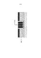
На Фиг. 3А показан первый независимый герметизированный биосовместимый элемент питания с примером расположения анодного и катодного контактов.In FIG. 3A shows a first independent sealed biocompatible battery with an example of the location of the anode and cathode contacts.
На Фиг. 3В показан второй независимый герметизированный биосовместимый элемент питания с примером расположения анодного и катодного контактов.In FIG. 3B shows a second independent sealed biocompatible battery with an example of the location of the anode and cathode contacts.
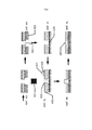
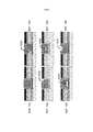
На Фиг. 4A-4N показаны примеры стадий способа изготовления биосовместимых элементов питания для биомедицинских устройств.In FIG. 4A-4N show examples of steps in a method for manufacturing biocompatible batteries for biomedical devices.
На Фиг. 5 показан пример полностью готового биосовместимого элемента питания.In FIG. 5 shows an example of a fully prepared biocompatible battery.
На Фиг. 6A-6F показаны примеры стадий способа изготовления конструкции биосовместимых элементов питания.In FIG. 6A-6F show examples of stages of a method for manufacturing a biocompatible battery design.
На Фиг. 7A-7F показаны примеры стадий способа формирования биосовместимых элементов питания с использованием альтернативного способа электроосаждения.In FIG. 7A-7F show examples of steps in a method for forming biocompatible batteries using an alternative electrodeposition method.
На Фиг. 8A-8H показаны примеры стадий способа изготовления биосовместимых элементов питания с гидрогелевым сепаратором для биомедицинских устройств.In FIG. 8A-8H show examples of steps in a method for manufacturing biocompatible batteries with a hydrogel separator for biomedical devices.
На Фиг. 9A-9C показаны примеры стадий способа формирования биосовместимых элементов питания с использованием альтернативных примеров обработки гидрогеля.In FIG. 9A-9C show examples of steps in a method for forming biocompatible batteries using alternative examples of hydrogel treatment.
На Фиг. 10A-10F показано оптимизированное и неоптимизированное осаждение катодной смеси в полость.In FIG. 10A-10F show optimized and non-optimized deposition of a cathode mixture into a cavity.
На Фиг. 11 показана агломерация катодной смеси в полости.In FIG. 11 shows agglomeration of the cathode mixture in a cavity.
На Фиг. 12A-12F показаны примеры использования гелеобразного электролита в биосовместимом элементе питания.In FIG. 12A-12F show examples of the use of a gelled electrolyte in a biocompatible battery.
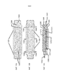
На Фиг. 13A-13C показаны примеры конфигураций герметизации и заключения в оболочку биосовместимого элемента питания.In FIG. 13A-13C show examples of sealing configurations and encapsulation of a biocompatible battery.
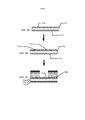
На Фиг. 14A-14H показаны примеры стадий способов герметизации и заключения в оболочку биосовместимого элемента питания.In FIG. 14A-14H show examples of stages of methods for sealing and encapsulating a biocompatible battery.
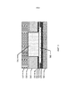
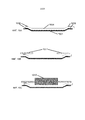
На Фиг. 15A-15D показаны примеры поперечного сечения выбранного в качестве примера элемента питания.In FIG. 15A-15D show examples of a cross section of an exemplary selected battery.
На Фиг. 16A-16G показаны альтернативные примеры стадий способов герметизации и заключения в оболочку биосовместимого элемента питания.In FIG. 16A-16G show alternative examples of stages of methods for sealing and enclosing a biocompatible battery.
ПОДРОБНОЕ ОПИСАНИЕ ИЗОБРЕТЕНИЯDETAILED DESCRIPTION OF THE INVENTION
В настоящей заявке описаны биотопливные элементы для применения в биосовместимой батарее. В следующих разделах приведены подробные описания различных примеров. Описания примеров представляют собой только примеры осуществления, и специалистам в данной области могут быть понятны различные модификации и изменения. Поэтому примеры не ограничивают объем настоящей заявки. Биотопливные элементы и содержащие их конструкции могут быть выполнены с возможностью применения в биосовместимых батареях. В некоторых примерах эти биосовместимые батареи могут быть выполнены с возможностью применения внутри или вблизи тела живого организма.This application describes biofuel cells for use in a biocompatible battery. The following sections provide detailed descriptions of various examples. The description of the examples are only examples of implementation, and specialists in this field can be understood various modifications and changes. Therefore, the examples do not limit the scope of this application. Biofuel cells and structures containing them can be configured to be used in biocompatible batteries. In some examples, these biocompatible batteries may be configured to be used within or near the body of a living organism.
ОпределенияDefinitions
В описании и представленной ниже формуле изобретения могут применяться различные термины, для которых применяются следующие определения.Various terms may be used in the description and claims below, for which the following definitions apply.
В настоящем документе термин «анод» относится к электроду, через который электрический ток втекает в поляризованное электрическое устройство. Направление электрического тока, как правило, противоположно направлению потока электронов. Иными словами, электроны текут из анода, например, в электрическую схему.As used herein, the term “anode” refers to an electrode through which an electric current flows into a polarized electrical device. The direction of the electric current is usually opposite to the direction of the electron flow. In other words, electrons flow from the anode, for example, into an electrical circuit.
В настоящем документе термин «связующее вещество» относится к полимеру, который способен показывать упругие отклики на механические деформации и который химически совместим с другими компонентами элемента питания. Например, связующие могут включать электроактивные материалы, электролиты, полимеры и т. п.As used herein, the term “binder” refers to a polymer that is capable of showing elastic responses to mechanical deformation and which is chemically compatible with other components of the battery. For example, binders may include electroactive materials, electrolytes, polymers, etc.
В настоящем документе термин «биосовместимый» относится к материалу или устройству, которое функционирует в конкретном приложении при соответствующем отклике носителя. Например, биосовместимое устройство не оказывает токсических или травмирующих воздействий на биологические системы.As used herein, the term “biocompatible” refers to a material or device that operates in a particular application with an appropriate response from the carrier. For example, a biocompatible device does not have toxic or traumatic effects on biological systems.
В настоящем документе термин «катод» относится к электроду, через который электрический ток вытекает из поляризованного электрического устройства. Направление электрического тока, как правило, противоположно направлению потока электронов. Следовательно, электроны текут в катод поляризованного электрического устройства и вытекают, например, из подключенной электрической схемы.As used herein, the term “cathode” refers to an electrode through which an electric current flows from a polarized electrical device. The direction of the electric current is usually opposite to the direction of the electron flow. Therefore, electrons flow into the cathode of a polarized electrical device and flow, for example, from a connected electrical circuit.
В настоящем документе термин «покрытие» относится к нанесению материала тонким слоем. В ряде применений этот термин будет относиться к тонкому слою, который по существу покрывает поверхность подложки, на которой формируется покрытие. В других более специализированных применениях этот термин может применяться для описания небольших тонких слоев на меньших областях поверхности.As used herein, the term “coating” refers to the application of a thin layer of material. In a number of applications, this term will refer to a thin layer that essentially covers the surface of the substrate on which the coating is formed. In other more specialized applications, this term can be used to describe small thin layers on smaller areas of the surface.
В настоящем документе термин «электрод» может относиться к активной массе в источнике энергии. Например, он может включать один или оба из анода и катода.As used herein, the term “electrode” may refer to the active mass in an energy source. For example, it may include one or both of the anode and cathode.
В настоящем документе термин «с энергообеспечением» относится к состоянию способности подачи электрического тока или хранения электрической энергии внутри.As used herein, the term “energy powered” refers to a state of being able to supply electric current or store electric energy inside.
В настоящем документе термин «энергия» относится к способности физической системы выполнять работу. Многие варианты применения элементов питания могут относиться к способности выполнять электрические действия.As used herein, the term “energy” refers to the ability of a physical system to do work. Many uses of batteries may relate to the ability to perform electrical activities.
В настоящем документе термин «источник энергии», или «элемент питания», или «устройство с энергообеспечением» относится к любому устройству или слою, который способен снабжать энергией или переводить логическое или электрическое устройство в состояние с энергообеспечением. Элементы питания могут включать батареи. Батареи могут быть образованы из гальванических элементов щелочного типа и могут представлять собой твердотельные батареи или батареи жидкостных элементов.As used herein, the term “power source”, or “battery cell” or “power supply device” refers to any device or layer that is capable of supplying energy or placing a logical or electrical device in a power supply state. Batteries may include batteries. The batteries may be formed of alkaline cells and may be solid state batteries or liquid cell batteries.
В настоящем документе термин «наполнители» относится к одному или более сепараторам элементов питания, которые не взаимодействуют ни с кислотными, ни с щелочными электролитами. Как правило, наполнители могут включать по существу не растворимые в воде материалы, такие как сажа; угольную пыль; графит; окиси и гидроксиды металлов, например кремния, алюминия, кальция, магния, бария, титана, железа, цинка и олова; карбонаты металлов, например кальция и магния; минералы, такие как слюда, монтмориллонит, каолинит, аттапульгит и тальк; синтетические и природные цеолиты, такие как портландцемент; осажденные силикаты металлов, такие как силикат кальция; полые или сплошные полимерные или стеклянные микросферы, хлопья и волокна и т. д.As used herein, the term “fillers” refers to one or more battery separators that do not interact with either acidic or alkaline electrolytes. Typically, fillers may include substantially water-insoluble materials such as carbon black; coal dust; graphite; metal oxides and hydroxides, for example silicon, aluminum, calcium, magnesium, barium, titanium, iron, zinc and tin; metal carbonates, for example calcium and magnesium; minerals such as mica, montmorillonite, kaolinite, attapulgite and talc; synthetic and natural zeolites, such as Portland cement; precipitated metal silicates, such as calcium silicate; hollow or solid polymer or glass microspheres, flakes and fibers, etc.
В настоящем документе термин «функционализированный» относится к получению слоя или устройства, способного выполнять некоторую функцию, включая, например, энергообеспечение, активацию и/или управление.As used herein, the term “functionalized” refers to a layer or device capable of performing a function, including, for example, power supply, activation, and / or control.
В настоящем документе термин «диссоциирующая в растворе соль» обозначает твердое вещество с ионными связями, которое растворяется в растворителе с образованием в растворе растворенных ионов. В многочисленных примерах растворитель может включать в себя воду.As used herein, the term “salt dissociating in a solution” means a solid with ionic bonds that dissolves in a solvent to form dissolved ions in the solution. In numerous examples, the solvent may include water.
В настоящем документе термин «форма для литья» относится к жесткому или полужесткому объекту, который можно применять для формирования трехмерных объектов из неполимеризованных составов. Некоторые примеры форм для литья включают две части формы для литья, которые при соединении друг с другом образуют конструкцию трехмерного объекта.As used herein, the term "mold" refers to a rigid or semi-rigid object that can be used to form three-dimensional objects from unpolymerized compositions. Some examples of injection molds include two parts of the injection mold that, when connected to each other, form a three-dimensional object structure.
В настоящем документе термин «мощность» относится к выполняемой работе или энергии, передаваемой за единицу времени.As used herein, the term “power” refers to work being performed or energy transferred per unit of time.
В настоящем документе термины «перезаряжаемый» или «повторно подключаемый к источнику питания» относятся к возможности восстановления до состояния с более высокой способностью выполнять работу. Во многих случаях эти термины могут относиться к возможности восстановления со способностью обеспечивать электрический ток определенной величины в течение определенных периодически повторяющихся промежутков времени.As used herein, the terms “rechargeable” or “reconnected to a power source” refer to the ability to recover to a state with a higher ability to perform work. In many cases, these terms may refer to the possibility of recovery with the ability to provide an electric current of a certain magnitude for certain periodically repeating periods of time.
В настоящем документе термины «перезаряжать» или «повторно подключать к источнику питания» относятся к восстановлению до состояния повышенной способности выполнять работу. Во многих случаях эти термины могут относиться к возможности восстановления устройства до способности обеспечивать электрический ток определенной величины в течение определенных, периодически повторяющихся промежутков времени.As used herein, the terms “recharge” or “reconnect to a power source” refer to recovering to a state of increased ability to perform work. In many cases, these terms may refer to the ability to restore the device to the ability to provide an electric current of a certain magnitude for certain periodically repeating periods of time.
В настоящем документе термин «высвобожденный», или иногда «высвобожденный из формы для литья», означает, что трехмерный объект либо полностью отделен от формы для литья, либо лишь слабо прикреплен к форме для литья, так что может быть извлечен легким встряхиванием.As used herein, the term “released”, or sometimes “released from a mold” means that the three-dimensional object is either completely detached from the mold or only loosely attached to the mold so that it can be removed by light shaking.
В настоящем документе термин «выступ сепаратора» означает элемент биосовместимого элемента питания, используемый для предотвращения короткого замыкания на кромке по периметру сепаратора путем реализации вырезанного сепаратора, жидкого сепаратора или комбинации двух вышеназванных сепараторов. Выступ сепаратора могут изготовлять из полимера, например из полипропилена, подвергать обработке (например, лазером) и размещать внутри конструкции элемента. Он должен состоять из материала, способного герметично соединяться с верхней и нижней пленками оболочки. Он может состоять из другого материала, например стекла или керамики, при условии, что такой материал можно разрезать и герметично соединить. В сочетании с жестким выступом сепаратора могут использовать адгезив, лак, эпоксидный состав, битум и т. п.As used herein, the term “separator protrusion” means a biocompatible battery cell used to prevent a short circuit at the edge around the perimeter of the separator by selling a cut-out separator, a liquid separator, or a combination of the two separators mentioned above. The protrusion of the separator can be made of polymer, for example polypropylene, subjected to processing (for example, a laser) and placed inside the structure of the element. It should consist of a material capable of hermetically connecting to the upper and lower films of the shell. It may consist of another material, such as glass or ceramic, provided that such material can be cut and hermetically joined. In combination with a rigid protrusion of the separator, adhesive, varnish, epoxy, bitumen, etc. can be used.
В настоящем документе термин «наложенный» означает размещение по меньшей мере двух слоев компонента вблизи друг друга таким образом, что по меньшей мере часть одной поверхности одного из слоев контактирует с первой поверхностью второго слоя. В некоторых примерах между двумя слоями может находиться покрытие, обеспечивающее сцепление или иные функции, и слои контактируют друг с другом через указанное покрытие.As used herein, the term “overlaid” means placing at least two component layers adjacent to each other so that at least a portion of one surface of one of the layers is in contact with a first surface of the second layer. In some examples, between the two layers may be a coating that provides adhesion or other functions, and the layers are in contact with each other through the specified coating.
В настоящем документе термин «дорожки» относится к компонентам элементов питания, способным соединять вместе компоненты схемы. Например, дорожки схемы могут включать медь или золото, если подложка представляет собой печатную плату, и, как правило, могут представлять собой пленку из меди, золота или печатного слоя в гибкой схеме. Токоотвод представляет собой «дорожку» особого типа. Токоотводы представляют собой дорожки с электрохимической совместимостью, из-за которой токоотводы подходят для применения при передаче электронов на анод или катод и от них в присутствии электролита.As used herein, the term “tracks” refers to battery components capable of connecting circuit components together. For example, circuit tracks may include copper or gold if the substrate is a printed circuit board, and typically can be a film of copper, gold, or a printed layer in a flexible circuit. The down conductor is a "track" of a special type. Down conductors are tracks with electrochemical compatibility, because of which down conductors are suitable for use in transferring electrons to and from the anode or cathode in the presence of an electrolyte.
Представленные в настоящем документе способы и устройство относятся к формированию биосовместимых элементов питания для включения внутрь или нанесения на поверхность плоских или трехмерных биосовместимых устройств. К особому классу элементов питания могут относиться батареи, составленные из слоев. Эти слои можно классифицировать как слои многослойного материала. Батарею, изготовленную таким образом, можно классифицировать как слоистую батарею.The methods and apparatus presented herein relate to the formation of biocompatible batteries for incorporation into or application of flat or three-dimensional biocompatible devices to the surface. A special class of batteries may include batteries made up of layers. These layers can be classified as layers of a multilayer material. A battery made in this way can be classified as a layered battery.
Могут быть и другие примеры способов сборки и изготовления батарей в соответствии с настоящим изобретением, и некоторые из них могут быть описаны в следующих разделах. Тем не менее для многих из этих примеров существуют выбранные параметры и характеристики батарей, которые могут быть описаны отдельно. В следующих разделах будет уделено внимание некоторым характеристикам и параметрам.There may be other examples of methods for assembling and manufacturing batteries in accordance with the present invention, and some of them may be described in the following sections. However, for many of these examples, there are selected parameters and battery characteristics that can be described separately. The following sections will focus on some features and parameters.
Пример конструкции биомедицинского устройства с биосовместимыми элементами питанияAn example of the design of a biomedical device with biocompatible batteries
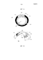
Одним из примеров биомедицинского устройства, в которое могут быть встроены элементы питания, или батареи, согласно настоящему изобретению, может быть электроактивная контактная линза с переменным фокусом. На Фиг. 1А в качестве примера вставки такой контактной линзы показана вставка 100 контактной линзы. Во вставке 100 контактной линзы может находиться электроактивный элемент 120, который может изменять фокусные характеристики в соответствии с управляющими сигналами напряжения. Схема 105 для обеспечения этих управляющих сигналов напряжения, а также для обеспечения других функций, таких как датчик, контролирующий условия окружающей среды для внешних контрольных сигналов, может получать электропитание от биосовместимого элемента 110 батареи. Как показано на Фиг. 1А, элемент 110 батареи может состоять из множества крупных деталей, в данном случае трех деталей, и может включать химические элементы батареи различной конфигурации, как описано выше. Элементы 110 батареи могут иметь различные соединительные элементы для соединения деталей, как показано на рисунке, лежащих ниже области соединения 114. Элементы 110 батареи могут быть подключены к элементу схемы, который может иметь собственную подложку 111, на которой могут быть размещены соединительные элементы 125. Схема 105, которая может быть выполнена в форме интегральной схемы, может иметь электрическую и физическую связь с подложкой 111 и ее соединительными элементами 125.One example of a biomedical device into which batteries or batteries according to the present invention can be incorporated may be a variable focus electroactive contact lens. In FIG. 1A, an example of a contact lens insert is shown as an example of an insert of such a contact lens. In the
На Фиг. 1В показано, что рельеф в поперечном сечении контактной линзы 150 может включать в себя вставку 100 контактной линзы и ее описанные выше компоненты. Вставка 100 контактной линзы может быть заключена в юбку гидрогеля 155 контактной линзы, который может содержать вставку 100 контактной линзы и обеспечивать комфортное соприкосновение контактной линзы 150 с глазом пользователя.In FIG. 1B shows that the relief in cross section of the
Согласно концепциям настоящего изобретения, элементы батареи могут быть изготовлены в двухмерной форме, как показано на Фиг. 1С. В этом отображении может быть две основные области элементов батареи в областях компонента 165 батареи и второй компонент батареи в области химического элемента 160 батареи. Элементы батареи, показанные в плоском виде на Фиг. 1C, можно подключить к элементу 163 схемы, который в примере, показанном на Фиг. 1С, может включать в себя две основные зоны 167 схемы. Элемент 163 схемы может быть подключен к элементу батареи электрическим контактом 161 и физическим контактом 162. Плоскую конструкцию можно согнуть в трехмерную коническую конструкцию, как указано в описании к настоящему изобретению. В этом способе второй электрический контакт 166 и второй физический контакт 164 можно применять для подключения и физической стабилизации трехмерной конструкции. На Фиг. 1D представлена эта трехмерная коническая структура 180. Можно также увидеть физические и электрические контактные клеммы 181, и иллюстрацию можно рассматривать как трехмерный вид итоговой конструкции. Эта конструкция может включать в себя модульный электрический компонент и компонент батареи, которые вместе со вставкой для линзы будут встроены в биосовместимое устройство.According to the concepts of the present invention, the battery cells can be manufactured in two-dimensional form, as shown in FIG. 1C. In this display, there may be two main areas of battery cells in the areas of the
Сегментные структуры батареиSegmented Battery Structures
На Фиг. 2 показаны примеры разных типов сегментных структур батареи для примера элемента батареи для типового примера контактной линзы. Сегментные компоненты могут быть относительно округлыми 271, квадратными 272 или прямоугольными по форме. В примерах прямоугольных форм прямоугольники могут быть небольшими прямоугольными формами 273, более крупными прямоугольными формами 274 или еще более крупными прямоугольными формами 275.In FIG. 2 shows examples of different types of segmented battery structures for an example of a battery cell for a typical contact lens example. Segment components may be relatively rounded 271, square 272, or rectangular in shape. In examples of rectangular shapes, the rectangles may be small
Индивидуальные формы плоских элементов батареиIndividual shaped flat battery cells
В некоторых примерах биосовместимых батарей батареи могут быть изготовлены в виде плоских элементов. На Фиг. 3А показан пример прямоугольного контура 310 элемента батареи с анодным контактом 311 и катодным контактом 312. На Фиг. 3В показан пример кругового контура 330 элемента батареи с анодным контактом 331 и катодным контактом 332.In some examples of biocompatible batteries, the batteries can be manufactured as flat cells. In FIG. 3A shows an example of a
В некоторых примерах батарей плоской формы контуры формы батареи можно по размерам и геометрии выполнить с возможностью соответствия индивидуальным продуктам. В дополнение к примерам с прямоугольными или округлыми контурами можно изготавливать индивидуальные контуры «свободной формы» или «произвольной формы», что может позволить оптимизировать конфигурацию батареи для соответствия конкретному продукту.In some examples of flat-shaped batteries, the contours of the shape of the battery can be made in size and geometry to suit individual products. In addition to examples with rectangular or rounded contours, individual “free-form” or “arbitrary-shape” contours can be made, which may allow optimizing the configuration of the battery to suit a specific product.
В типовом случае биомедицинского устройства с изменяемыми оптическими свойствами плоский контур свободной формы может быть дугообразным по форме. Свободная форма может быть такой геометрии, что при образовании трехмерной формы она может принимать форму конической кольцевой юбки, которая соответствует ограничивающим пределам контактной линзы. Очевидно, что аналогичные эффективные геометрии можно изготавливать в случае медицинских устройств, имеющих ограничивающие требования к двухмерной или трехмерной форме.In a typical case of a biomedical device with variable optical properties, a free-form planar contour may be arched in shape. The free form can be such a geometry that, when a three-dimensional form is formed, it can take the form of a conical annular skirt, which corresponds to the limiting limits of the contact lens. Obviously, similar effective geometries can be made in the case of medical devices having restrictive requirements for a two-dimensional or three-dimensional shape.
Аспекты биосовместимости батарейBattery biocompatibility aspects
В качестве примера к батареям в соответствии с настоящим изобретением могут применяться важные аспекты, касающиеся безопасности и биосовместимости. В некоторых примерах батареи для биомедицинских устройств должны удовлетворять требованиям, выходящим за рамки типовых сценариев применения. В некоторых примерах можно учитывать аспекты конфигурации, касающиеся случаев нагрузки. Например, может потребоваться учесть безопасность электронной контактной линзы для случаев, когда пользователь ломает линзу в процессе ее установки или извлечения. В другом примере аспекты конфигурации могут учитывать вероятность удара пользователя посторонним предметом в глаз. В дополнительных примерах условия нагрузки, которые можно учитывать при разработке параметров и ограничений конфигурации, могут относиться к вероятности ношения пользователем линз в неблагоприятных условиях окружающей среды, таких как окружающая среда под водой или окружающая среда на большой высоте, в качестве примеров, не имеющих ограничительного характера.By way of example, important aspects regarding safety and biocompatibility can be applied to batteries in accordance with the present invention. In some examples, batteries for biomedical devices must meet requirements that go beyond typical application scenarios. In some examples, configuration aspects regarding load cases can be considered. For example, you may need to consider the safety of an electronic contact lens for cases where the user breaks the lens during installation or removal. In another example, aspects of the configuration may take into account the likelihood of a user striking a foreign object in the eye. In further examples, load conditions that can be considered when designing configuration parameters and limitations may relate to the likelihood of the user wearing lenses under adverse environmental conditions, such as the environment under water or the environment at high altitude, as non-restrictive examples. .
Безопасность такого устройства может зависеть от материалов, с помощью или из которых изготовлено устройство, от количеств этих материалов, использованных при изготовлении устройства, а также от оболочки, применяемой для отделения устройств от окружающей среды на теле или внутри тела. В одном примере кардиостимуляторы могут быть типичным примером биомедицинского устройства, которое может включать батарею и которое может быть имплантировано пользователю на длительный период времени. Соответственно, в некоторых примерах такие кардиостимуляторы, как правило, могут быть заключены в герметизированные сваркой титановые корпусы, или, в других примерах, во множество слоев оболочки. Новые биомедицинские устройства с электропитанием могут представлять дополнительные сложности в том, что касается оболочки, особенно оболочки батарей. Эти новые устройства могут быть намного мельче существующих биомедицинских устройств; например, электронная контактная линза или камера-таблетка могут быть значительно мельче кардиостимулятора. В таких примерах объем и площадь, имеющиеся для оболочки, могут быть значительно сокращены.The safety of such a device may depend on the materials with which or from which the device is made, on the quantities of these materials used in the manufacture of the device, as well as on the sheath used to separate the devices from the environment on the body or inside the body. In one example, pacemakers may be a typical example of a biomedical device that can include a battery and that can be implanted to the user for a long period of time. Accordingly, in some examples, such pacemakers, as a rule, can be enclosed in welded sealed titanium cases, or, in other examples, in many layers of the shell. Newer biomedical powered devices may present additional challenges for the shell, especially the battery shell. These new devices can be much smaller than existing biomedical devices; for example, an electronic contact lens or a tablet camera can be significantly smaller than a pacemaker. In such examples, the volume and area available for the shell can be significantly reduced.
Требования по электропитанию микробатарейMicro Battery Power Requirements
Другой аспект конфигурации может относиться к требованиям по электропитанию устройства, которое может обеспечивать батарея. Для функционирования в качестве источника питания для медицинского устройства соответствующей батарее может потребоваться полностью удовлетворять требованиям по электропитанию системы при эксплуатации в автономном режиме или без внешних источников питания. Новая область биомедицинских устройств, работающих автономно или без внешних источников питания, может включать, например, контактные линзы для коррекции зрения, устройства для контроля за состоянием здоровья, камеры-таблетки и другие новые устройства. Последние разработки в области технологии интегральных схем (ИС) могут позволять эксплуатировать электрические устройства на очень низких уровнях тока, например на уровне пикоампер для тока холостого хода и на уровне микроампер для рабочего тока. ИС могут позволять также значительно уменьшить размеры устройств.Another aspect of the configuration may relate to the power requirements of the device that the battery can provide. To function as the power source for a medical device, the appropriate battery may need to fully meet the system's power requirements when operating in stand-alone mode or without external power sources. A new area of biomedical devices operating autonomously or without external power supplies may include, for example, contact lenses for vision correction, health monitoring devices, tablet cameras, and other new devices. Recent developments in the field of integrated circuit technology (IC) can allow the operation of electrical devices at very low current levels, for example, at the level of picoamperes for no-load current and at the level of microamperes for operating current. ICs can also significantly reduce the size of devices.
Микробатареям для биомедицинских сфер применения может быть необходимо одновременно удовлетворять ряду сложных требований. Например, от микробатарей может требоваться наличие возможности обеспечивать подходящее рабочее напряжение для встроенных электрических схем. Это рабочее напряжение может зависеть от нескольких факторов, включая функциональный «узел» ИС, выходное напряжение со схемы на другое устройство, а также конкретный целевой показатель по потребляемому току, который также может относиться к расчетному сроку службы устройства.Micro-batteries for biomedical applications may need to simultaneously meet a number of complex requirements. For example, microbatteries may be required to be able to provide a suitable operating voltage for integrated electrical circuits. This operating voltage may depend on several factors, including the functional “node” of the IC, the output voltage from the circuit to another device, as well as a specific target indicator for the current consumption, which can also relate to the estimated service life of the device.
С точки зрения функции ИС, узлы, как правило, могут различаться по минимальному размеру элемента транзистора, такому как так называемая «ширина линии». Этот физический элемент, наряду с другими параметрами производства ИС, такими как толщина слоя подзатворной окиси, может быть связан с полученным номинальным пороговым напряжением, или напряжением включения полевых транзисторов (FET), произведенных для конкретного функционального узла. Например, в узле с минимальным размером элемента 0,5 микрона, как правило, применяют полевые транзисторы с напряжением включения 5,0 В. Однако при минимальном размере элемента 90 нм полевые транзисторы могут включаться при напряжении 1,2, 1,8 и 2,5 В. Изготовители ИС могут поставлять стандартные элементы цифровых блоков, например инверторы и триггеры, с характеристиками, соответствующими определенным диапазонам напряжения. Конструкторы выбирают функциональный узел ИС на основании ряда факторов, включая плотность цифровых устройств, возможность совмещения в устройствах аналоговых и цифровых схем, ток утечки, количество слоев соединений и доступность специальных устройств, таких как полевые транзисторы высокого напряжения. С учетом этих параметрических аспектов электрических компонентов, которые могут получать электропитание от микробатареи, может быть важно обеспечить, чтобы источник питания микробатареи соответствовал требованиям выбранного функционального узла и конфигурации ИС, особенно с точки зрения доступного уровня напряжения и тока.From the point of view of the function of the IC, the nodes, as a rule, can differ in the minimum size of the transistor element, such as the so-called "line width". This physical element, along with other parameters for the production of ICs, such as the thickness of the gate oxide layer, can be associated with the obtained nominal threshold voltage, or the field voltage of the field effect transistors (FET), produced for a particular functional unit. For example, in a node with a minimum element size of 0.5 microns, as a rule, field effect transistors with a switching voltage of 5.0 V are used. However, with a minimum element size of 90 nm, field effect transistors can turn on at a voltage of 1.2, 1.8, and 2, 5 V. IC manufacturers can supply standard digital block components, such as inverters and triggers, with characteristics corresponding to specific voltage ranges. Designers select the functional component of the IC based on a number of factors, including the density of digital devices, the ability to combine analog and digital circuits in devices, leakage current, the number of connection layers, and the availability of special devices, such as high voltage field effect transistors. Given these parametric aspects of the electrical components that can receive power from the micro-battery, it may be important to ensure that the micro-battery power supply meets the requirements of the selected functional unit and IC configuration, especially in terms of the available voltage and current levels.
В некоторых примерах электрическая схема, получающая электропитание от микробатареи, может быть подключена к другому устройству. В примерах, не имеющих ограничительного характера, электрическая схема, получающая электропитание от микробатареи, может быть подключена к исполнительному устройству или преобразователю. В зависимости от сферы применения это может быть светодиод (LED), датчик, микроэлектромеханический (MEMS) дозатор и многие другие подобные устройства. В некоторых примерах подключаемым таким образом устройствам может требоваться более высокое рабочее напряжение, чем стандартным функциональным узлам ИС. Например, для активации линзы с переменным фокусом может потребоваться 35 В. Следовательно, рабочее напряжение, обеспечиваемое батареей, может быть критическим фактором при проектировании такой системы. В некоторых примерах, связанных с такими факторами, эффективность привода линзы, преобразующего напряжение батареи 1 В в напряжение 35 В, может быть значительно ниже, чем эффективность привода, работающего от батареи 2 В. Дополнительные требования, такие как размер кристалла, могут значительно различаться, в том числе с учетом рабочих параметров микробатареи.In some examples, an electrical circuit receiving power from the micro-battery may be connected to another device. In non-limiting examples, an electrical circuit receiving power from the micro-battery may be connected to an actuator or converter. Depending on the application, it can be a light emitting diode (LED), a sensor, a microelectromechanical (MEMS) dispenser, and many other similar devices. In some examples, devices connected in this way may require a higher operating voltage than the standard functional units of the IC. For example, 35 V may be required to activate a zoom lens. Therefore, the operating voltage provided by the battery can be a critical factor in designing such a system. In some examples related to such factors, the efficiency of a lens drive that converts a 1 V battery voltage to 35 V can be significantly lower than the efficiency of a 2 V battery drive. Additional requirements, such as crystal size, can vary significantly. including taking into account the operating parameters of the microbattery.
Отдельные элементы батареи, как правило, могут характеризоваться напряжением при разомкнутой цепи, напряжением с нагрузкой и напряжением отсечки. Напряжение при разомкнутой цепи представляет собой потенциал, создаваемый элементом батареи при бесконечном сопротивлении нагрузки. Напряжение с нагрузкой представляет собой потенциал, создаваемый элементом при подключении к выводам элемента нагрузки с соответствующей, и, как правило, также установленной величиной полного сопротивления. Напряжение отсечки представляет собой, как правило, напряжение, при котором большая часть батареи разряжена. Напряжение отсечки может представлять собой напряжение, или степень разряда, ниже которого батарею нельзя разряжать во избежание нежелательных последствий, таких как сильное выделение газов. Напряжение отсечки может зависеть, как правило, не от самой батареи, а от схемы, к которой подключена батарея, например от рабочего напряжения электронной схемы. В одном примере щелочной элемент может иметь напряжение при разомкнутой цепи 1,6 В, напряжение с нагрузкой в диапазоне от 1,0 до 1,5 В и напряжение отсечки 1,0 В. Напряжение, создаваемое элементом микробатареи конкретной конфигурации, может зависеть и от других характеристик используемого химического состава элемента. И поэтому разные по химическому составу элементы могут иметь разные напряжения элемента.Individual battery cells, as a rule, can be characterized by open circuit voltage, load voltage and cut-off voltage. An open circuit voltage is the potential created by a battery cell with infinite load resistance. Voltage with load is the potential created by the element when connected to the terminals of the load element with the corresponding, and, as a rule, also set value of the impedance. The cut-off voltage is typically the voltage at which most of the battery is discharged. The cut-off voltage may be a voltage, or a degree of discharge, below which the battery cannot be discharged in order to avoid undesirable consequences, such as strong gas emissions. The cut-off voltage may depend, as a rule, not on the battery itself, but on the circuit to which the battery is connected, for example, on the operating voltage of the electronic circuit. In one example, an alkaline cell may have an open circuit voltage of 1.6 V, a voltage with a load in the range of 1.0 to 1.5 V, and a cut-off voltage of 1.0 V. The voltage generated by the microbattery element of a specific configuration may also depend on other characteristics of the chemical composition of the element used. And therefore, elements of different chemical composition can have different element voltages.
Для увеличения напряжения элементы можно соединять последовательно, однако эта комбинация может повлечь за собой увеличение размеров, повышение внутреннего сопротивления и усложнение батареи. Элементы также можно объединять в параллельные конфигурации, чтобы снизить сопротивление и увеличить емкость, однако эта комбинация может повлечь за собой увеличение размера батареи и сокращение срока хранения.To increase the voltage, the elements can be connected in series, but this combination can entail an increase in size, an increase in internal resistance, and a complication of the battery. Cells can also be combined in parallel configurations to reduce resistance and increase capacity, but this combination can lead to an increase in battery size and shortened shelf life.
Емкость батареи может представлять собой способность батареи производить ток, или выполнять работу, в течение определенного периода времени. Емкость батареи можно, как правило, указать в таких единицах, как микроампер-часы. Батарея, которая может обеспечивать 1 микроампер тока в течение 1 часа, имеет емкость 1 микроампер-час. Как правило, емкость батареи можно повысить путем увеличения массы (и, следовательно, объема) реагентов внутри устройства батареи; тем не менее следует учитывать, что биомедицинские устройства могут быть существенно ограничены по доступному объему. Емкость батареи также может зависеть от материала электрода и электролита.A battery capacity may be the ability of a battery to produce current, or perform work, over a period of time. Battery capacity can usually be specified in units such as microamp hours. A battery that can provide 1 microampere of current for 1 hour has a capacity of 1 microampere-hour. Typically, the battery capacity can be increased by increasing the mass (and therefore volume) of the reagents inside the battery device; Nevertheless, it should be borne in mind that biomedical devices can be significantly limited in terms of available volume. Battery capacity may also depend on electrode material and electrolyte.
В зависимости от требований к схеме, к которой подключена батарея, от батареи может требоваться служить источником тока определенного диапазона величин. В период хранения до активного применения через схемы, соединения и изоляторы может протекать ток утечки величиной порядка от нескольких пикоампер до нескольких наноампер. В период активной эксплуатации схема может потреблять ток покоя для считывания показаний датчиков, запуска таймеров и выполнения других подобных функций с низким энергопотреблением. Потребление тока покоя может составлять величину порядка от нескольких наноампер до нескольких миллиампер. Схема также может иметь еще большие потребности по пиковому току, например при записи данных в ПЗУ или при их передаче на радиочастоте (РЧ). Этот пиковый ток может составлять до нескольких десятков миллиампер или более. Активное и полное сопротивление микробатареи также может быть важным для аспектов конфигурации.Depending on the requirements of the circuit to which the battery is connected, the battery may be required to serve as a current source of a certain range of values. During storage until active use, leakage current of a magnitude of the order of several picoamperes to several nanoamperes can flow through circuits, connections, and insulators. During active operation, the circuit can consume a quiescent current to read sensors, start timers and perform other similar functions with low power consumption. Quiescent current consumption can range from a few nanoamps to a few milliamps. The circuit may also have even greater peak current requirements, for example, when writing data to a ROM or when transmitting it on a radio frequency (RF). This peak current can be up to several tens of milliamps or more. Active and impedance microbatteries can also be important for configuration aspects.
Срок хранения, как правило, относится к периоду времени, в течение которого батарея может поддерживать подходящие рабочие параметры. Срок хранения может быть особенно важным для биомедицинских устройств по нескольким причинам. Электронные устройства могут заменять собой устройства, не подключаемые к электропитанию, например в случае внедрения электронных контактных линз. Продукты в этих существующих сегментах рынка могут иметь установленные требования к срокам хранения, например три года, исходя из пожеланий потребителей, особенностей цепочки поставок и других требований. Как правило, считается нежелательным, чтобы такие технические требования менялись для новых продуктов. Требования к сроку хранения могут быть также установлены с учетом факторов распределения, инвентаризации и способов применения устройства, включающего микробатарею. Соответственно, микробатареи для биомедицинских устройств могут иметь конкретные требования к сроку хранения, которые можно измерять, например, в количестве лет.Shelf life generally refers to the period of time during which the battery can maintain suitable operating parameters. Shelf life can be especially important for biomedical devices for several reasons. Electronic devices can replace devices that are not connected to power, for example, in the case of electronic contact lenses. Products in these existing market segments may have established requirements for shelf life, for example, three years, based on the wishes of consumers, the characteristics of the supply chain and other requirements. It is generally considered undesirable for such specifications to change for new products. Requirements for the shelf life can also be established taking into account the factors of distribution, inventory and methods of use of the device, including the micro-battery. Accordingly, microbatteries for biomedical devices may have specific shelf life requirements that can be measured, for example, in the number of years.
В некоторых примерах трехмерные биосовместимые элементы питания могут быть перезаряжаемыми. Например, индукционная катушка может быть также изготовлена на трехмерной поверхности. Индукционная катушка затем может получать энергообеспечение с помощью радиочастотного (РЧ) импульса. Индукционную катушку можно подключить к трехмерному биосовместимому элементу питания для подзарядки элемента питания при подаче РЧ на индукционную катушку. В другом примере фотоэлектрические устройства также можно изготовить на трехмерной поверхности и подключить к трехмерному биосовместимому элементу питания. Под действием света или фотонов фотоэлектрические устройства будут продуцировать электроны для подзарядки элемента питания.In some examples, three-dimensional biocompatible batteries may be rechargeable. For example, an induction coil can also be made on a three-dimensional surface. The induction coil can then be powered by a radio frequency (RF) pulse. The induction coil can be connected to a three-dimensional biocompatible battery to recharge the battery when applying RF to the induction coil. In another example, photovoltaic devices can also be made on a three-dimensional surface and connected to a three-dimensional biocompatible battery. Under the influence of light or photons, photovoltaic devices will produce electrons to recharge the battery.
В некоторых примерах батареи могут функционировать для обеспечения электрической энергии для электрической системы. В этих примерах батареи могут находиться в электрической связи со схемой электрической системы. Связи между схемой и батареей можно классифицировать как соединения. Эти соединения могут со временем стать сложной задачей для биомедицинских микробатарей ввиду нескольких факторов. В некоторых примерах биомедицинские устройства с электропитанием могут быть очень маленькими, предоставляя таким образом малые площади и объемы для соединений. Ограничения по размеру и площади могут отрицательно повлиять на величину электрического сопротивления и надежность соединений.In some examples, the batteries may function to provide electrical energy to the electrical system. In these examples, the batteries may be in electrical communication with the circuitry of the electrical system. The connections between the circuit and the battery can be classified as connections. These compounds can become a challenge for biomedical microbatteries over time due to several factors. In some examples, biomedical powered devices can be very small, thus providing small areas and volumes for connections. Restrictions on size and area can adversely affect the value of electrical resistance and the reliability of the connections.
Кроме того, батарея может содержать жидкий электролит, который может закипать при высокой температуре. Это ограничение может вступать в прямое противоречие с желанием применять соединение пайкой, что может, например, потребовать относительно высоких температур, таких как 250 градусов Цельсия, для расплавления припоя. Несмотря на это, в некоторых примерах химический состав батареи, включая электролит, и источник тепла, применяемый для формирования соединений пайкой, могут быть пространственно изолированы друг от друга. В случаях новых биомедицинских устройств небольшой размер может препятствовать разделению электролита и паяных соединений на достаточное расстояние для уменьшения переноса тепла.In addition, the battery may contain liquid electrolyte, which can boil at high temperature. This limitation may directly conflict with the desire to use the solder joint, which may, for example, require relatively high temperatures, such as 250 degrees Celsius, to melt the solder. Despite this, in some examples, the chemical composition of the battery, including the electrolyte, and the heat source used to form the compounds by soldering, can be spatially isolated from each other. In the case of new biomedical devices, the small size may prevent separation of the electrolyte and soldered joints at a sufficient distance to reduce heat transfer.
СоединенияConnections
Соединения могут позволять току течь к батарее и от батареи, находящейся в соединении с внешней схемой. Такие соединения могут взаимодействовать с окружающей средой внутри и снаружи батареи и могут пересекать границу или уплотнительный слой между этими средами. Эти соединения можно рассматривать как дорожки, выполняющие соединения с внешней схемой, проходящие через уплотнительный слой батареи и затем соединяющиеся с токоотводами внутри батареи. Как таковые эти соединения могут иметь несколько требований. За пределами батареи соединения могут быть похожи на типичные проводники печатной платы. Они могут быть припаяны или иным способом соединены с другими дорожками. В примере, где батарея представляет собой физический элемент, отдельный от печатной платы, включающей в себя интегральную схему, соединения батареи могут обеспечивать связь с внешней схемой. Эта связь может быть сформирована с помощью припоя, проводящей ленты, проводящей пасты или эпоксидного состава либо других средств. Для соединительных дорожек может потребоваться оставаться сохранными в условиях среды, окружающей батарею, например не ржаветь в присутствии кислорода.Connections can allow current to flow to and from the battery in connection with an external circuit. Such compounds may interact with the environment inside and outside the battery and may cross the boundary or seal layer between these environments. These connections can be thought of as tracks making connections to an external circuit, passing through the sealing layer of the battery and then connecting to the down conductors inside the battery. As such, these compounds may have several requirements. Outside the battery, the connections may look like typical circuit board conductors. They can be soldered or otherwise connected to other tracks. In an example where the battery is a physical element separate from a printed circuit board including an integrated circuit, battery connections can provide communication with an external circuit. This bond can be formed using solder, conductive tape, conductive paste or epoxy, or other means. Connection paths may need to remain intact in the environment surrounding the battery, such as not rusting in the presence of oxygen.
Поскольку соединение проходит через уплотнительный слой батареи, может быть чрезвычайно важно, чтобы соединение было совместимо с материалом уплотнительного слоя и не нарушало герметичность. Адгезия может потребоваться между уплотнительным слоем и соединением в дополнение к адгезии, которая может потребоваться между уплотнительным слоем и герметичной оболочкой батареи. При наличии электролита и других материалов внутри батареи может потребоваться поддержание целостности уплотнительного слоя. Соединения, которые, как правило, могут быть металлическими, могут быть известны как точки разрушения в оболочке батареи. Электрический потенциал и/или течение тока могут усиливать тенденцию «просачивания» электролита вдоль соединения. Соответственно, для соединения может потребоваться проектирование, поддерживающее целостность уплотнительного слоя.Since the connection passes through the sealing layer of the battery, it can be extremely important that the connection is compatible with the material of the sealing layer and does not break the seal. Adhesion may be required between the sealing layer and the joint in addition to the adhesion that may be required between the sealing layer and the sealed battery shell. In the presence of electrolyte and other materials inside the battery, it may be necessary to maintain the integrity of the sealing layer. Compounds, which, as a rule, can be metal, can be known as points of destruction in the battery shell. The electric potential and / or current flow may increase the tendency for electrolyte to “leak” along the junction. Accordingly, a design that maintains the integrity of the sealing layer may be required for the connection.
Внутри батареи соединения могут взаимодействовать с токоотводами или могут сами быть токоотводами. В связи с этим для соединений может требоваться удовлетворять описанным в настоящем документе требованиям к токоотводам либо образовывать электрическое соединение с такими токоотводами.Inside the battery, the connections can interact with down conductors or can themselves be down conductors. In this regard, for connections, it may be necessary to satisfy the requirements for down conductors described in this document or to form an electrical connection with such down conductors.
Один класс возможных соединений и токоотводов представляет собой металлическую фольгу. Такая фольга имеется толщиной 25 микрон или менее, что делает ее подходящей для очень тонких батарей. Такую фольгу также можно найти с низкими шероховатостью и загрязнением поверхности - эти два фактора могут быть критичными для эффективности батареи. Фольга может включать цинк, никель, латунь, медь, титан, другие металлы и различные сплавы.One class of possible connections and down conductors is metal foil. Such foil is available in a thickness of 25 microns or less, which makes it suitable for very thin batteries. Such foil can also be found with low roughness and surface contamination - these two factors can be critical to battery performance. The foil may include zinc, nickel, brass, copper, titanium, other metals and various alloys.
Компоненты модульной батареиModular Battery Components
В некоторых примерах можно изготовить компонент модульной батареи в соответствии с некоторыми аспектами и примерами настоящего изобретения. В этих примерах узел модульной батареи может быть компонентом, отдельным от других частей биомедицинского устройства. В примере устройства офтальмологической контактной линзы такая конфигурация может включать модульную батарею, которая является отдельной от остальной части несущей вставки. Существует множество преимуществ изготовления компонента модульной батареи. Например, в примере контактной линзы компонент модульной батареи можно изготовить в ходе отдельного, независимого процесса, что может ослабить необходимость в манипуляциях с жесткими трехмерными оптическими пластиковыми компонентами. Кроме того, средства изготовления могут быть более гибкими и могут выполнять операции в более параллельном режиме с изготовлением других компонентов биомедицинского устройства. Более того, изготовление компонентов модульной батареи может не зависеть от характеристик устройств трехмерной (3D) формы. Например, в сферах применения, требующих окончательных трехмерных форм, систему модульной батареи можно изготовить в плоском или приблизительно двухмерном (2D) виде, а затем придать ей соответствующую трехмерную форму. Компонент модульной батареи можно испытывать независимо от остальной части биомедицинского устройства, и потерю выхода из-за компонентов батареи можно отбраковать до начала сборки. Полученный компонент модульной батареи можно использовать в различных конструкциях несущей вставки, которые не имеют соответствующей жесткой области, на которой можно образовать компоненты батареи; а в дополнительном примере применение компонентов модульной батареи может облегчить применение вариантов технологий производства, отличных от тех, что можно было бы использовать в ином случае, таких как рулонная (roll-to-roll) технология, листовая (sheet-to-sheet) технология, печать, литография и ракельная печать. В некоторых примерах модульной батареи аспект отдельной оболочки такого устройства может привести к добавлению дополнительного материала к общей конструкции биомедицинского устройства. Такие воздействия могут установить ограничение на применение решений в виде модульных батарей в случаях, когда параметры имеющегося пространства требуют минимизировать толщину или объем решений.In some examples, a modular battery component may be manufactured in accordance with some aspects and examples of the present invention. In these examples, the modular battery assembly may be a component separate from other parts of the biomedical device. In an example ophthalmic contact lens device, such a configuration may include a modular battery that is separate from the rest of the carrier insert. There are many advantages to making a modular battery component. For example, in the example of a contact lens, the components of a modular battery can be manufactured in a separate, independent process, which can reduce the need for manipulation of rigid three-dimensional optical plastic components. In addition, the manufacturing tools can be more flexible and can perform operations in a more parallel mode with the manufacture of other components of the biomedical device. Moreover, the manufacture of components of a modular battery may not depend on the characteristics of three-dimensional (3D) shape devices. For example, in applications requiring final three-dimensional shapes, a modular battery system can be manufactured in a flat or approximately two-dimensional (2D) form, and then given it an appropriate three-dimensional shape. The modular battery component can be tested independently of the rest of the biomedical device, and the loss of output due to battery components can be discarded before assembly. The resulting component of the modular battery can be used in various designs of the carrier insert, which do not have a corresponding rigid region on which the battery components can be formed; and in an additional example, the use of components of a modular battery can facilitate the application of production technology options that are different from those that could otherwise be used, such as roll-to-roll technology, sheet-to-sheet technology, printing, lithography and doctor blade printing. In some examples of a modular battery, the aspect of a separate shell of such a device may lead to the addition of additional material to the overall design of the biomedical device. Such influences may limit the use of solutions in the form of modular batteries in cases where the parameters of the available space require minimizing the thickness or volume of solutions.
Требования к форме батареи могут быть обусловлены, по меньшей мере частично, сферой применения батареи. Традиционные форм-факторы батарей могут быть цилиндрическими формами или прямоугольными призмами, изготовленными из металла, и их можно использовать для продуктов, которые требуют больших объемов энергии в течение длительного времени. Такие сферы применения имеют достаточно большие размеры, чтобы включать в себя батареи крупных форм-факторов. В другом примере плоские (2D) твердотельные батареи представляют собой тонкие прямоугольные призмы, как правило, образованные на жестком кремнии или стекле. В некоторых примерах эти плоские твердотельные батареи можно изготавливать с применением технологий обработки кремниевых пластин. Форм-факторы батарей другого типа, маломощные, но гибкие батареи, можно изготавливать в виде пакетов с применением тонкой фольги или пластика, которые содержат химические элементы батареи. Эти батареи можно сделать плоскими (2D) и выполнить с возможностью функционирования при умеренной поперечной (3D) кривизне.Battery shape requirements may be determined, at least in part, by the scope of the battery. The traditional form factors of batteries can be cylindrical shapes or rectangular prisms made of metal, and can be used for products that require large amounts of energy for a long time. Such applications are large enough to include large form factor batteries. In another example, flat (2D) solid state batteries are thin rectangular prisms, typically formed on hard silicon or glass. In some examples, these flat solid state batteries can be manufactured using silicon wafer processing techniques. The form factors of another type of battery, low-power but flexible batteries, can be made in the form of bags using thin foil or plastic, which contain the chemical elements of the battery. These batteries can be made flat (2D) and can be operated with moderate transverse (3D) curvature.
В некоторых примерах применения батареи в соответствии с настоящим изобретением, где батареи можно использовать в линзах с изменяемыми оптическими свойствами, форм-фактор может потребовать создания трехмерной кривизны компонента батареи, причем радиус этой кривизны может быть порядка приблизительно 8,4 мм. Характер такой кривизны может считаться относительно резким и, в качестве сравнения, может приближаться к типу кривизны кончика пальца человека. Характер относительно резкой кривизны создает сложности при изготовлении. В некоторых примерах настоящего изобретения компонент модульной батареи может быть выполнен так, что он может быть изготовлен плоским, двухмерным, а затем сформирован в трехмерную форму относительно большой кривизны.In some examples of battery applications in accordance with the present invention, where batteries can be used in lenses with variable optical properties, the form factor may require the creation of a three-dimensional curvature of the battery component, the radius of this curvature being on the order of approximately 8.4 mm. The nature of such curvature can be considered relatively sharp and, as a comparison, can approach the type of curvature of a person’s finger. The nature of the relatively sharp curvature creates difficulties in manufacturing. In some examples of the present invention, the component of the modular battery can be made so that it can be made flat, two-dimensional, and then formed in three-dimensional shape with a relatively large curvature.
Толщина модуля батареиBattery Module Thickness
При проектировании компонентов батареи для биомедицинских сфер применения можно корректировать различные параметры, находя компромисс между техническими и функциональными требованиями, а также требованиями безопасности. Толщина компонента батареи может быть важным и ограничивающим параметром. Например, в сфере применения оптической линзы от толщины биомедицинского устройства может в значительной мере зависеть способность устройства быть комфортным при ношении пользователем. Поэтому существуют важные аспекты при проектировании батарей, позволяющие сделать их более тонкими. В некоторых примерах толщина батареи может определяться сочетанием толщин верхнего и нижнего слоев, разделительного слоя и слоя адгезива. Практические аспекты изготовления могут потребовать соответствия определенных параметров толщины пленки стандартным значениям для имеющегося листового материала. Кроме того, пленки могут иметь минимальные значения толщины, которые могут быть установлены на основании технических соображений, касающихся химической совместимости, проницаемости для жидкостей и газов, обработки поверхности и совместимости с покрытиями, которые могут быть нанесены поверх слоев пленки.When designing battery components for biomedical applications, various parameters can be adjusted to find a compromise between technical and functional requirements as well as safety requirements. The thickness of the battery component can be an important and limiting parameter. For example, in the field of application of an optical lens, the ability of a device to be comfortable when worn by a user can largely depend on the thickness of a biomedical device. Therefore, there are important aspects when designing batteries that make them thinner. In some examples, the thickness of the battery can be determined by a combination of the thicknesses of the upper and lower layers, the separation layer and the adhesive layer. Practical manufacturing aspects may require certain film thickness parameters to meet standard values for existing sheet material. In addition, films can have minimum thicknesses that can be set based on technical considerations regarding chemical compatibility, liquid and gas permeability, surface treatment, and compatibility with coatings that can be applied over film layers.
В некоторых примерах требуемая, или целевая, толщина готового компонента батареи может представлять собой толщину компонента, составляющую менее 220 мкм. В этих примерах эта требуемая толщина может быть обусловлена трехмерной геометрией примера устройства офтальмологической линзы, причем может потребоваться поместить компонент батареи внутрь имеющегося объема, образованного формой гидрогелевой линзы, с учетом определенного уровня комфорта конечного пользователя, биосовместимости и критериев приемлемости. Этот объем линзы и его воздействие на требования к толщине компонента батареи могут зависеть от общих технических требований к толщине устройства, а также технических требований к ширине, углу конуса и внутреннему диаметру устройства. Другой важный аспект конфигурации итогового компонента батареи может относиться к объему, доступному для активных химических веществ и материалов батареи, с учетом определенной конфигурации компонента батареи в отношении итоговой химической энергии, которая может стать результатом такой конфигурации. Эта итоговая химическая энергия может затем быть сбалансирована для удовлетворения требований по электропитанию функционального биомедицинского устройства для целевых условий его срока службы и эксплуатации.In some examples, the desired, or target, thickness of the finished battery component may be a component thickness of less than 220 microns. In these examples, this required thickness may be due to the three-dimensional geometry of an example of an ophthalmic lens device, and it may be necessary to place the battery component inside the existing volume formed by the shape of the hydrogel lens, taking into account a certain level of end-user comfort, biocompatibility and acceptance criteria. This lens volume and its effect on the thickness requirements of the battery component may depend on the general technical requirements for the thickness of the device, as well as the technical requirements for the width, cone angle and internal diameter of the device. Another important aspect of the configuration of the final battery component may relate to the volume available for the active chemicals and materials of the battery, taking into account the specific configuration of the battery component with respect to the total chemical energy that may result from such a configuration. This resulting chemical energy can then be balanced to meet the power requirements of a functional biomedical device for the target conditions of its life and operation.
Гибкость модуля батареиBattery Module Flexibility
Другим критерием соответствия конфигурации батареи и конфигурации соответствующих устройств, которые используют источники энергии на основе батарей, является гибкость компонента батареи. Существует множество преимуществ, предоставляемых гибкими формами батареи. Например, гибкий модуль батареи может обеспечить вышеупомянутую возможность изготовления батареи двухмерной (2D) плоской формы. Гибкость формы может позволить двухмерной батарее быть затем преобразованной в соответствующую трехмерную форму, соответствующую форме биомедицинского устройства, такого как контактная линза.Another criterion for matching the configuration of the battery with the configuration of the corresponding devices that use battery-based energy sources is the flexibility of the battery component. There are many advantages provided by flexible forms of batteries. For example, a flexible battery module may provide the aforementioned capability of manufacturing a two-dimensional (2D) flat-shaped battery. The shape flexibility can allow a two-dimensional battery to then be converted to a corresponding three-dimensional shape, corresponding to the shape of a biomedical device, such as a contact lens.
В другом примере преимуществ, которые могут быть предоставлены гибкостью модуля батареи, если батарея и последующее устройство являются гибкими, то могут возникнуть преимущества, относящиеся к применению устройства. В одном примере форма контактной линзы биомедицинского устройства может иметь преимущества для установки/извлечения контактной линзы с несущей вставкой, что может больше напоминать установку/извлечение стандартной, не заполненной гидрогелевой контактной линзы.In another example of the advantages that can be afforded by the flexibility of a battery module, if the battery and the subsequent device are flexible, then advantages related to the use of the device may arise. In one example, the contact lens shape of a biomedical device may have advantages for mounting / removing a contact lens with a carrier insert, which may be more reminiscent of installing / removing a standard, unfilled hydrogel contact lens.
Количество изгибаний может быть важным для проектирования батареи. Например, батарея, которая допускает только одно изгибание при переходе от плоской формы к форме, подходящей для контактной линзы, может значительно отличаться по конфигурации от батареи, допускающей множество изгибаний. Изгибание батареи также может превышать ее устойчивость к механическому изгибу. Например, электрод может иметь физическую способность изгибаться без разрушения, но при этом механические и электрохимические свойства электрода могут изменяться из-за изгибания. Изменения, происходящие в результате изгибания, могут проявляться сразу же, например в виде изменений полного сопротивления, либо изгибание может вызвать изменения, которые становятся заметными только в ходе испытаний, проводимых после длительного хранения.The amount of bending can be important for designing a battery. For example, a battery that allows only one bend when moving from a flat shape to a shape suitable for a contact lens can vary significantly in configuration from a battery that allows many bends. Bending the battery may also exceed its resistance to mechanical bending. For example, an electrode may have a physical ability to bend without breaking, but the mechanical and electrochemical properties of the electrode may vary due to bending. Changes that occur as a result of bending can occur immediately, for example in the form of changes in the impedance, or bending can cause changes that become noticeable only during tests conducted after long-term storage.
Ширина модуля батареиBattery Module Width
Существует множество сфер применения, в которых можно использовать биосовместимые элементы питания или батареи настоящего изобретения. В целом требование к ширине батареи в основном обусловлено сферой ее применения. В типовом случае система батареи контактной линзы может иметь ограничения в технических требованиях к ширине компонента модульной батареи. В некоторых примерах офтальмологического устройства, где устройство имеет функцию с изменяемыми оптическими свойствами с электропитанием от компонента батареи, часть устройства, имеющая изменяемые оптические свойства, может занимать центральную сферическую область диаметром приблизительно 7,0 мм. Элементы батареи в этих примерах можно рассматривать как трехмерный объект, который размещается как коническая кольцевая юбка вокруг центрального оптического участка и образует усеченное коническое кольцо. Если требуемый максимальный диаметр жесткой вставки составляет 8,50 мм, а угол касательной к сфере определенного диаметра можно задать (например, приблизительно 8,40 мм), то геометрия может определить допустимую ширину батареи. Существуют геометрические модели, которые могут быть подходящими для расчета желательных технических параметров для итоговой геометрии, которая в некоторых примерах может представлять собой усеченный конус, развернутый в виде сектора кольцевой зоны.There are many applications where the biocompatible batteries or batteries of the present invention can be used. In general, the requirement for the width of the battery is mainly due to the scope of its application. In a typical case, the contact lens battery system may have limitations in the technical requirements for the width of the component of the modular battery. In some examples of an ophthalmic device, where the device has a function with variable optical properties and is powered by a battery component, a portion of the device having variable optical properties may occupy a central spherical region with a diameter of approximately 7.0 mm. The battery cells in these examples can be considered as a three-dimensional object, which is placed as a conical annular skirt around the central optical section and forms a truncated conical ring. If the required maximum diameter of the rigid insert is 8.50 mm and the angle of tangent to the sphere of a certain diameter can be set (for example, approximately 8.40 mm), then the geometry can determine the permissible width of the battery. There are geometric models that may be suitable for calculating the desired technical parameters for the final geometry, which in some examples may be a truncated cone, deployed in the form of a sector of the annular zone.
Ширина развернутой батареи может быть обусловлена двумя компонентами элемента батареи: активными компонентами батареи и шириной уплотнительного слоя. В некоторых примерах, относящихся к офтальмологическим устройствам, требуемая толщина может быть в пределах от 0,100 мм до 0,500 мм на сторону, а ширина активных компонентов батареи может быть установлена как приблизительно 0,800 мм. Другие биомедицинские устройства могут иметь другие ограничения конфигурации, но принципы для гибких плоских элементов батареи могут применяться аналогичным образом.The width of the deployed battery may be due to two components of the battery cell: the active components of the battery and the width of the sealing layer. In some examples related to ophthalmic devices, the required thickness can be in the range of 0.100 mm to 0.500 mm per side, and the width of the active components of the battery can be set to approximately 0.800 mm. Other biomedical devices may have other configuration limitations, but the principles for flexible flat battery cells can be applied in a similar way.
Полости как элементы конфигурации в конфигурации компонента батареиCavities as configuration items in a battery component configuration
В некоторых примерах элементы батареи могут быть выполнены таким образом, что обеспечивают разделение областей активного химического состава батареи на сегменты. Существует множество преимуществ разделения активных компонентов батареи на отдельные сегменты. В качестве примера, не имеющего ограничительного характера, изготовление отдельных и более мелких элементов может ускорить производство элементов. Функционирование элементов батареи, включающих множество мелких элементов, может быть улучшено. В некоторых случаях можно разделить дефекты разного рода и изолировать нефункциональные элементы, что приводит к снижению потерь функциональности. Это может быть существенно в примерах, где может происходить потеря электролита батареи. Изолирование отдельных компонентов может позволить дефекту, который приводит к утечке электролита из критических областей батареи, ограничить потерю функциональности этим маленьким сегментом всего элемента батареи, тогда как потеря электролита по причине дефекта может опустошить значительно большую область в батареях, изготовленных как единый элемент. Более мелкие элементы могут привести к снижению объема активных химических веществ батареи в общей перспективе, но сеть из материала, окружающего каждый из более мелких элементов, может привести к усилению общей конструкции.In some examples, the battery cells may be configured to separate segments of the active chemical composition of the battery into segments. There are many advantages to dividing the active components of a battery into separate segments. By way of non-limiting example, the manufacture of individual and smaller elements can accelerate the production of elements. The performance of battery cells, including many small cells, can be improved. In some cases, it is possible to separate defects of various kinds and isolate non-functional elements, which leads to a decrease in loss of functionality. This may be significant in examples where battery electrolyte loss can occur. Insulating individual components can allow a defect that leads to leakage of electrolyte from critical areas of the battery to limit the loss of functionality to this small segment of the entire battery cell, while loss of electrolyte due to a defect can devastate a much larger area in batteries manufactured as a single cell. Smaller cells can lead to a decrease in the volume of active chemicals in the battery in the general perspective, but a network of material surrounding each of the smaller cells can lead to an increase in overall design.
Сепараторы элементов батареиBattery Cell Separators
Батареи типа, описанного в настоящем изобретении, могут использовать материал сепаратора, который физически и электрически отделяет части анода и анодного токоотвода от частей катода и катодного токоотвода. Сепаратор может представлять собой мембрану, проницаемую для воды и растворенных компонентов электролита; однако, как правило, он может быть не электропроводен. Несмотря на то что специалистам в данной области может быть известно большое количество коммерчески доступных материалов сепаратора, новый форм-фактор настоящего изобретения может представлять уникальные ограничения в задаче выбора, обработки и использования сепаратора.Batteries of the type described in the present invention can use a separator material that physically and electrically separates parts of the anode and the anode collector from parts of the cathode and the cathode collector. The separator may be a membrane permeable to water and dissolved electrolyte components; however, as a rule, it may not be electrically conductive. Although a large number of commercially available separator materials may be known to those skilled in the art, the new form factor of the present invention may present unique limitations in the selection, processing and use of the separator.
Поскольку конфигурации настоящего изобретения могут иметь сверхтонкие профили, выбор может быть ограничен наиболее тонким из имеющихся материалов сепаратора. Например, могут быть желательны сепараторы толщиной приблизительно 25 микрон. Некоторые примеры, которые могут быть преимущественными, могут иметь толщину приблизительно 12 микрон. Существует множество приемлемых коммерческих сепараторов, включая разделительные мембраны из однослойного микроволокнистого, микропористого полиэтилена и/или трехслойные разделительные мембраны полипропилен-полиэтилен-полипропилен (ПП/ПЭ/ПП), такие как те, что производит компания Celgard (г. Шарлотт, штат Северная Каролина, США). Желательным примером материала сепаратора может быть трехслойная мембрана Celgard M824 ПП/ПЭ/ПП, имеющая толщину 12 микрон. Альтернативные примеры материалов сепаратора, подходящие для примеров настоящего изобретения, могут включать разделительные мембраны, включающие в себя регенерированную целлюлозу (например, целлофан).Since the configurations of the present invention may have ultra-thin profiles, the selection may be limited to the thinnest separator materials available. For example, approximately 25 microns thick separators may be desirable. Some examples that may be advantageous may have a thickness of about 12 microns. There are many suitable commercial separators, including single-layer microfibre, microporous polyethylene and / or three-layer polypropylene-polyethylene-polypropylene (PP / PE / PP) separation membranes, such as those manufactured by Celgard (Charlotte, North Carolina) , USA). A desirable example of a separator material may be a Celgard M824 PP / PE / PP three-layer membrane having a thickness of 12 microns. Alternative examples of separator materials suitable for the examples of the present invention may include separation membranes including regenerated cellulose (e.g., cellophane).
Несмотря на то что трехслойные разделительные мембраны ПП/ПЭ/ПП могут иметь преимущества из-за толщины и механических свойств, благодаря их полиолефиновому характеру они также могут иметь ряд недостатков, которые необходимо преодолеть для того, чтобы они подходили для примеров настоящего изобретения. Рулонные или листовые трехслойные материалы сепаратора ПП/ПЭ/ПП могут иметь многочисленные складки или другие нарушения формы, которые могут быть нежелательными для допусков на уровне микронов, применимых к батареям, описанным в настоящем документе. Более того, может быть необходимо разрезать с высокой точностью полиолефиновые сепараторы для включения в настоящие конфигурации, что, следовательно, может подразумевать лазерную резку в качестве примера способа формирования отдельных токоотводов желательных форм с жесткими допусками. Вследствие полиолефинового характера этих сепараторов некоторые лазерные резаки, подходящие для микропроизводства, которые могут использовать длины волн лазера, например 355 нм, будут не в состоянии разрезать полиолефины. Полиолефины не поглощают энергию лазерного излучения в ощутимых количествах и, таким образом, являются неразрушаемыми. Наконец, полиолефиновые сепараторы по своей природе не могут смачиваться водными электролитами, которые применяются в батареях, описанных в настоящих документах.Although three-layer PP / PE / PP separation membranes may have advantages due to their thickness and mechanical properties, due to their polyolefin nature, they can also have a number of disadvantages that must be overcome in order to be suitable for examples of the present invention. The roll or sheet three-layer materials of the PP / PE / PP separator may have numerous creases or other irregular shapes that may be undesirable for micron tolerances applicable to the batteries described herein. Moreover, it may be necessary to cut the polyolefin separators with high precision for inclusion in the present configurations, which, therefore, may include laser cutting as an example of the method of forming individual down conductors of desired shapes with tight tolerances. Due to the polyolefin nature of these separators, some laser cutters suitable for microproduction that can use laser wavelengths, such as 355 nm, will not be able to cut polyolefins. Polyolefins do not absorb laser energy in appreciable quantities and are thus indestructible. Finally, polyolefin separators, by their nature, cannot be wetted by aqueous electrolytes, which are used in the batteries described in these documents.
Тем не менее существуют способы преодоления этих присущих мембранам полиолефинового типа ограничений. Для того чтобы подвергать микропористую разделительную мембрану воздействию высокоточного лазерного резака для резки деталей на дугообразные сегменты или другие преимущественные конфигурации сепаратора, от мембраны может требоваться быть плоской и свободной от складок. Если эти два условия не выполнены, разделительная мембрана не может быть полностью разрезана, так как режущий луч может быть ослаблен в результате нарушения фокусировки или иного рассеивания падающей лазерной энергии. Кроме того, если разделительная мембрана не является плоской и свободной от складок, точность формы и геометрические допуски разделительной мембраны не могут быть достижимы в достаточной мере. Допустимые отклонения для сепараторов в текущих примерах могут, например, составлять +0 микрон и -20 микрон в отношении характеристических длин и/или радиусов. Могут существовать преимущества для более жестких допусков в +0 микрон и -10 микрон и дополнительно для допусков в +0 микрон и -5 микрон. Сырьевой материал сепаратора можно сделать плоским и свободным от складок путем временного ламинирования материала на подложке из флоат-стекла с помощью соответствующей низколетучей жидкости. Низколетучие жидкости могут быть более предпочтительны по сравнению с временными адгезивами ввиду хрупкости разделительной мембраны и ввиду количества времени на обработку, которое может потребоваться для высвобождения разделительной мембраны из слоя адгезива. Кроме того, в некоторых примерах получение плоской и свободной от складок разделительной мембраны на флоат-стекле с применением жидкости оказалось намного более легким, чем с применением адгезива. Перед ламинированием разделительную мембрану можно очистить от твердых частиц. Это можно выполнить путем ультразвуковой очистки разделительной мембраны для удаления всех прилипших к поверхности твердых частиц. В некоторых примерах обработку разделительной мембраны можно выполнить в подходящей среде с низким содержанием частиц, такой как слоистый бокс или чистая комната класса по меньшей мере 10 000. Кроме того, подложку из флоат-стекла можно очистить от частиц путем промывки соответствующим растворителем, ультразвуковой очистки и/или протирки салфетками для чистых комнат.However, there are ways to overcome these inherent limitations of polyolefin-type membranes. In order to expose a microporous separation membrane to a high-precision laser cutter for cutting parts into arched segments or other preferred separator configurations, the membrane may need to be flat and wrinkle-free. If these two conditions are not fulfilled, the separation membrane cannot be completely cut, since the cutting beam can be weakened as a result of imbalance in focus or other dispersion of the incident laser energy. In addition, if the separation membrane is not flat and wrinkled-free, the accuracy of the shape and geometric tolerances of the separation membrane cannot be sufficiently achieved. Tolerances for separators in the current examples may, for example, be +0 microns and -20 microns with respect to characteristic lengths and / or radii. There may be advantages for tighter tolerances of +0 microns and -10 microns, and additionally for tolerances of +0 microns and -5 microns. The raw material of the separator can be made flat and free from wrinkles by temporarily laminating the material on a float glass substrate using an appropriate low-volatility liquid. Low volatile liquids may be preferred over temporary adhesives because of the fragility of the separation membrane and the amount of processing time that may be required to release the separation membrane from the adhesive layer. In addition, in some examples, the preparation of a flat and wrinkle-free separation membrane on float glass using a liquid turned out to be much easier than using an adhesive. Before lamination, the separation membrane can be cleaned of solid particles. This can be accomplished by ultrasonic cleaning of the separation membrane to remove all particulate adhering to the surface. In some examples, processing the separation membrane can be performed in a suitable, low-particle environment, such as a laminate box or a cleanroom of at least 10,000 class. In addition, the float glass substrate can be cleaned of particles by washing with an appropriate solvent, ultrasonic cleaning, and / or wipes for clean rooms.
Несмотря на то что для механической цели ламинирования микропористых полиолефиновых разделительных мембран на подложке из флоат-стекла можно применять самые разные низколетучие жидкости, к жидкости могут применяться конкретные требования для облегчения последующей лазерной резки отдельных форм сепаратора. Одним требованием может быть наличие у жидкости достаточно низкого поверхностного натяжения, чтобы проникать в поры материала сепаратора, в чем можно легко удостовериться путем визуальной проверки. В некоторых примерах материал сепаратора меняет белый цвет на прозрачный, когда жидкость заполняет микропоры материала. Может быть желательным выбор жидкости, которая может быть благоприятной и «безопасной» для рабочих, которые будут выполнять операции подготовки и резки сепаратора. Может быть желательным выбор жидкости, давление паров которой будет достаточно низким, так чтобы не возникало заметного испарения в период обработки (порядка 1 суток). Наконец, в некоторых примерах жидкость может иметь достаточную сольватирующую способность, чтобы растворять преимущественные УФ-абсорберы, что может облегчить лазерную резку. В одном примере оказалось, что 12%-й (по весу) раствор авобензона (УФ-абсорбер) в бензилбензоате (растворитель) может удовлетворять вышеуказанным требованиям и может быть пригоден для облегчения лазерной резки полиолефиновых сепараторов с высокой точностью и в пределах допусков через небольшие промежутки времени и без избыточного числа проходов луча лазерного резака. В некоторых примерах сепараторы можно резать с помощью твердотельного лазера 8 В 355 нм с диодной накачкой и наносекундными импульсами с применением этого подхода, причем лазер может быть настроен на низкую мощность затухания (например, мощность 3%), среднюю скорость от 1 до 10 мм/с и только от 1 до 3 проходов лазерного луча. Несмотря на то что эта УФ-абсорбирующая маслообразная композиция оказалась эффективным вспомогательным средством для ламинирования и резки, специалисты в данной области могут без ограничений использовать другие маслообразные составы.Although for the mechanical purpose of laminating microporous polyolefin dividing membranes on a float glass substrate, a variety of low-volatile liquids can be applied, specific requirements can be applied to the liquid to facilitate subsequent laser cutting of individual separator shapes. One requirement may be that the fluid has a sufficiently low surface tension to penetrate the pores of the separator material, which can be easily verified by visual inspection. In some examples, the separator material changes white to transparent when the liquid fills the micropores of the material. It may be desirable to select a fluid that can be beneficial and “safe” for workers who will perform separator preparation and cutting operations. It may be desirable to select a liquid whose vapor pressure is sufficiently low so that there is no appreciable evaporation during the treatment period (of the order of 1 day). Finally, in some examples, the liquid may have sufficient solvating ability to dissolve the predominant UV absorbers, which may facilitate laser cutting. In one example, it turned out that a 12% (by weight) solution of avobenzene (UV absorber) in benzyl benzoate (solvent) can satisfy the above requirements and can be used to facilitate laser cutting of polyolefin separators with high accuracy and within tolerances at small intervals time and without an excessive number of passes of the laser cutter beam. In some examples, the separators can be cut using an 8 V 355 nm solid-state laser with diode pumping and nanosecond pulses using this approach, and the laser can be tuned to a low attenuation power (for example, a power of 3%), an average speed of 1 to 10 mm / with and only 1 to 3 passes of the laser beam. Despite the fact that this UV-absorbing oily composition has proven to be an effective adjuvant for laminating and cutting, those skilled in the art can use other oily compositions without limitation.
В некоторых примерах сепаратор можно резать закрепленным на флоат-стекле. Одним преимуществом лазерной резки сепараторов, закрепленных на подложке из флоат-стекла, может быть то, что из одного сырьевого листа сепаратора можно вырезать очень большое число сепараторов; так же как и то, что полупроводниковые кристаллы можно плотно разместить на одной кремниевой пластине. Такой подход может обеспечить преимущества экономии на масштабе и параллельной обработке, характерные для полупроводниковых технологий. Кроме того, можно минимизировать образование некондиционных разделительных мембран. После того как сепараторы разрезаны, маслообразная текучая среда вспомогательного средства может быть удалена путем многостадийной экстракции с помощью смешивающихся растворителей, причем последняя экстракция может быть выполнена с помощью высоколетучего растворителя, такого как изопропиловый спирт в некоторых примерах. Отдельные сепараторы после экстракции можно хранить неопределенное количество времени в любой подходящей среде с низким содержанием частиц.In some examples, the separator can be cut mounted on float glass. One advantage of laser cutting separators mounted on a float glass substrate may be that a very large number of separators can be cut from a single raw material separator sheet; as well as the fact that semiconductor crystals can be densely placed on a single silicon wafer. This approach can provide the economies of scale and parallel processing that are characteristic of semiconductor technology. In addition, the formation of substandard separation membranes can be minimized. After the separators are cut, the oily fluid of the adjuvant can be removed by multi-stage extraction using miscible solvents, the latter extraction being possible using a highly volatile solvent such as isopropyl alcohol in some examples. Separate separators after extraction can be stored indefinitely in any suitable, low-particle environment.
Как установлено выше, полиолефиновые разделительные мембраны могут быть по своей природе гидрофобными и могут требовать смачивания водными поверхностно-активными веществами, применяемыми в батареях настоящего изобретения. Одним подходом к обеспечению смачиваемости разделительных мембран может быть обработка кислородной плазмой. Например, сепараторы можно обрабатывать от 1 до 5 минут 100%-ной кислородной плазмой в широком диапазоне настроек мощности и расхода кислорода. Несмотря на то что такой подход может улучшить смачиваемость на некоторое время, известно, что модификации поверхностей плазмой обеспечивают лишь временный эффект, который не может длиться достаточно долго для надежного смачивания растворов электролита. Другой подход к улучшению смачиваемости разделительных мембран может заключаться в обработке поверхности путем встраивания в мембрану подходящих поверхностно-активных веществ. В некоторых случаях поверхностно-активное вещество можно применять в сочетании с гидрофильным полимерным покрытием, которое остается внутри пор разделительной мембраны.As stated above, polyolefin separation membranes may be inherently hydrophobic and may require wetting with the aqueous surfactants used in the batteries of the present invention. One approach to ensuring the wettability of separation membranes may be oxygen plasma treatment. For example, separators can be treated for 1 to 5 minutes with 100% oxygen plasma over a wide range of oxygen power and flow settings. Although this approach can improve wettability for a while, it is known that plasma surface modifications provide only a temporary effect that cannot last long enough to reliably wet the electrolyte solutions. Another approach to improving the wettability of separation membranes may be surface treatment by incorporating suitable surfactants into the membrane. In some cases, the surfactant can be used in combination with a hydrophilic polymer coating that remains inside the pores of the separation membrane.
Другой подход к обеспечению стойкости гидрофильности, обеспеченной обработкой кислородной плазмой, может заключаться в последующей обработке подходящим гидрофильным органосиланом. Таким образом, кислородную плазму можно применять для активации и обеспечения функциональных групп по всей площади поверхности микропористого сепаратора. Затем органосилан может ковалентно привязаться и/или нековалентно приклеиться к поверхности, обработанной плазмой. В примерах, где применяется органосилан, характерная пористость микропористого сепаратора может и не претерпеть заметных изменений; однослойное покрытие поверхности также может быть возможным и желательным. Известные в области способы встраивания поверхностно-активных веществ в сочетании с полимерными покрытиями могут требовать строгого контроля над фактическим объемом покрытия, нанесенного на мембрану, и потому могут проявлять технологическую нестабильность. В крайних случаях поры сепаратора могут закупориться, таким образом негативно воздействуя на функциональность сепаратора во время эксплуатации электрохимического элемента. Примером органосилана, подходящего для настоящего изобретения, может быть (3-аминопропил)триэтоксисилан. Специалистам в данной области могут быть известны и другие гидрофильные органосиланы, которые можно применять без ограничений.Another approach to ensuring the hydrophilicity resistance provided by the treatment with oxygen plasma may be subsequent treatment with a suitable hydrophilic organosilane. Thus, oxygen plasma can be used to activate and provide functional groups over the entire surface area of the microporous separator. Then, the organosilane can be covalently attached and / or non-covalently adhered to the plasma treated surface. In examples where organosilane is used, the characteristic porosity of the microporous separator may not undergo noticeable changes; a single layer surface coating may also be possible and desirable. Known in the art are methods for incorporating surfactants in combination with polymer coatings, which may require strict control over the actual amount of coating applied to the membrane, and therefore may exhibit technological instability. In extreme cases, the pores of the separator can become clogged, thereby adversely affecting the functionality of the separator during operation of the electrochemical cell. An example of an organosilane suitable for the present invention is (3-aminopropyl) triethoxysilane. Other hydrophilic organosilanes that may be used without limitation may be known to those skilled in the art.
Еще один способ обеспечения смачиваемости разделительных мембран водными электролитами может заключаться во встраивании подходящего поверхностно-активного вещества в состав электролита. Одним соображением при выборе поверхностно-активного вещества для обеспечения смачиваемости разделительных мембран может быть воздействие, которое поверхностно-активное вещество может оказывать на активность одного или более электродов внутри электрохимического элемента, например за счет повышения полного электрического сопротивления элемента. В некоторых случаях поверхностно-активные вещества могут иметь преимущественные антикоррозионные свойства, в частности в случае присутствия цинковых анодов в водных электролитах. Известно, что цинк медленно взаимодействует с водой с выделением газообразного водорода, что может быть нежелательно. Специалистам в данной области может быть известен ряд поверхностно-активных веществ, ограничивающих скорость указанного взаимодействия до преимущественных уровней. В других случаях поверхностно-активное вещество может так сильно взаимодействовать с поверхностью цинковых электродов, что функционирование батареи может быть затруднено. Следовательно, выбору соответствующих типов поверхностно-активных веществ и уровней их загрузки следует уделять особое внимание, чтобы обеспечить смачиваемость сепаратора без неблагоприятного воздействия на электрохимические показателей элемента. В некоторых случаях можно применять множество поверхностно-активных веществ, при этом одни придают смачиваемость разделительной мембране, а другие усиливают антикоррозийные свойства цинкового анода. В одном примере гидрофильная обработка разделительной мембраны не проводится, но в состав электролита добавляется одно или множество поверхностно-активных веществ в количестве, достаточном для обеспечения смачиваемости разделительной мембраны.Another way to ensure the wettability of the separation membranes with aqueous electrolytes may be to incorporate a suitable surfactant into the electrolyte. One consideration when choosing a surfactant to ensure the wettability of the separation membranes can be the effect that the surfactant can exert on the activity of one or more electrodes within the electrochemical cell, for example by increasing the electrical resistance of the cell. In some cases, surfactants can have predominant anticorrosion properties, in particular in the case of the presence of zinc anodes in aqueous electrolytes. It is known that zinc slowly interacts with water to produce hydrogen gas, which may be undesirable. Specialists in this field may be aware of a number of surfactants that limit the rate of this interaction to preferential levels. In other cases, the surfactant may interact so strongly with the surface of the zinc electrodes that the functioning of the battery may be difficult. Therefore, particular attention should be paid to the selection of appropriate types of surfactants and their loading levels in order to ensure the wettability of the separator without adversely affecting the electrochemical characteristics of the element. In some cases, many surfactants can be used, with some imparting wettability to the separation membrane, while others enhance the anti-corrosion properties of the zinc anode. In one example, hydrophilic treatment of the separation membrane is not performed, but one or a plurality of surfactants is added to the electrolyte in an amount sufficient to ensure wettability of the separation membrane.
Отдельные сепараторы можно внедрить внутрь слоистой микробатареи путем непосредственного помещения внутрь средства для хранения, включая выполненную полость, выемку или конструкцию внутри узла. Желательно, чтобы это средство для хранения могло быть образовано слоистой структурой, имеющей вырез, который может представлять собой геометрическую коррекцию формы сепаратора, позволяющую получить полость, выемку или конструкцию внутри узла. Более того, средство для хранения может иметь выступ или ступеньку, на которой находится сепаратор во время сборки. Выступ или ступенька может необязательно включать самоклеящийся адгезив, который удерживает отдельный сепаратор. Преимуществом является то, что самоклеящийся адгезив может быть тем же, что применяется в конструировании и наложении других элементов примера слоистой микробатареи.Separate separators can be inserted inside the layered microbatteries by directly placing the storage means inside, including a cavity, a recess or structure inside the assembly. It is desirable that this storage means can be formed by a layered structure having a cutout, which may be a geometric correction of the shape of the separator, allowing you to get a cavity, a recess or structure inside the node. Moreover, the storage means may have a protrusion or step on which the separator is located during assembly. The protrusion or step may optionally include a self-adhesive adhesive that holds a separate separator. The advantage is that the self-adhesive adhesive can be the same as that used in the design and application of other elements of the example of a layered micro-battery.
Иллюстрации примеров обработки биосовместимых элементов питания - помещение сепаратораIllustrations of Examples of Processing Biocompatible Batteries - Separator Room
Пример стадий, которые могут выполняться при обработке биосовместимых элементов питания, показан на Фиг. 4A-4N. На отдельных фигурах могут быть показаны некоторые примеры стадий обработки. На Фиг. 4А показана комбинация монтажного слоя 401 ПЭТ катода и монтажного слоя 404 ПЭТ сепаратора. Монтажный слой 401 ПЭТ катода может быть образован путем наложения пленок ПЭТ 403, которые могут иметь толщину, например, приблизительно 0,003 дюйма. Слой ПЭТ с обеих сторон может быть покрыт слоями PSA или защищен антиадгезионным слоем 402 из ПВДФ, который может иметь толщину приблизительно 0,001 дюйма. Монтажный слой 404 ПЭТ сепаратора может быть образован слоем 409 ПВДФ, который может иметь толщину приблизительно 0,003 дюйма. Может быть защитный слой 405 ПЭТ, который может иметь толщину приблизительно 0,0005 дюйма. В некоторых примерах между слоем 409 ПВДФ и защитным слоем 405 ПЭТ может находиться слой PSA.An example of steps that can be performed in processing biocompatible batteries is shown in FIG. 4A-4N. The individual figures may show some examples of processing steps. In FIG. 4A shows a combination of an
Как показано на Фиг. 4B, отверстие 406 в монтажном слое 404 сепаратора ПЭТ может быть вырезано лазером. Далее, как показано на Фиг. 4С, разрезанный монтажный слой 404 ПЭТ сепаратора можно наложить 408 на монтажный слой 401 ПЭТ катода. Как показано на Фиг. 4D, отверстие 410 в монтажном слое катода может быть вырезано лазером. Центрирование на этой стадии вырезания можно совместить с элементами, вырезанными ранее в монтажном слое 404 ПЭТ сепаратора. Как показано на Фиг. 4Е, слой Celgard 412, конечный разделительный слой, может быть прикреплен к носителю 411. Как показано на Фиг. 4F, из материала Celgard можно вырезать фигуры, которые по размеру находятся между размером предыдущих двух отверстий, вырезанных лазером, и приблизительным размером отверстия 406 в монтажном слое ПЭТ, для формирования заготовки сепаратора 420. Как показано на Фиг. 4G, манипулятор 421 можно применять для перекладывания отдельных частей из материала Celgard в соответствующие местоположения на формируемом устройстве. Как показано на Фиг. 4H, помещенные части 422 материала Celgard закрепляются в своем местоположении, после чего антиадгезионный слой 423 ПВДФ можно удалить. Как показано на Фиг. 4I, конструкцию формируемого устройства можно прикрепить к пленке анода 425. Анод 425 может включать в себя пленку анодного токоотвода, на которую методом электроосаждения нанесена пленка цинкового анода.As shown in FIG. 4B, the
Как показано на Фиг. 4J, в образованную полость можно поместить катодную пасту 430. В некоторых примерах можно применять ракель 431 для распределения катодной смеси по изделию и в процессе заполнения полостей формируемых устройств батареи. После заполнения оставшийся антиадгезионный слой 432 ПВДФ можно удалить, в результате чего может получиться конструкция, показанная на Фиг. 4К. Как показано на Фиг. 4L, всю конструкцию можно подвергнуть сушке, в процессе которой катодная паста 440 может дать усадку до уровня внешней поверхности слоя ПЭТ. Как показано на Фиг. 4М, слой 450 катодной пленки, на котором уже может находиться пленка катодного токоотвода, можно прикрепить к формируемой конструкции. Как показано на конечной иллюстрации на Фиг. 4N, способ лазерной резки можно применять для удаления боковых областей 460 и получения элемента 470 батареи. Существует множество модификаций, исключений и изменений материалов и значений толщины, которые могут подходить для целей настоящего изобретения.As shown in FIG. 4J,
Результат примера обработки более подробно показан на Фиг. 5. В одном из примеров можно определить следующие стандартные элементы. Химические вещества 510 катода могут быть размещены в контакте с катодом и катодным токоотводом 520. Слой 530 самоклеящегося адгезива может удерживать и герметично прикреплять катодный токоотвод 520 к монтажному слою 540 ПЭТ. На другой стороне монтажного слоя 540 ПЭТ может быть нанесен другой слой 550 PSA, который герметизирует и прикрепляет монтажный слой 540 ПЭТ к слою 560 сепаратора. Другой слой 565 PSA может герметизировать и прикреплять слой 560 сепаратора ПЭТ к слоям анода и анодного токоотвода. На анодный токоотвод 580 может быть нанесен слой 570 цинка. Разделительный слой 590 может быть размещен внутри конструкции для выполнения соответствующих функций, определенных в настоящем изобретении. В некоторых примерах во время обработки устройства можно добавлять электролит, в других примерах сепаратор может уже включать электролит.The result of the processing example is shown in more detail in FIG. 5. In one example, the following standard elements can be defined. The
Иллюстрации примеров обработки биосовместимых элементов питания - осаждение сепаратораIllustrations of Examples of Processing Biocompatible Batteries - Separator Deposition
Пример стадий, которые могут выполняться при обработке биосовместимых элементов питания, показан на Фиг. 6A-6F. На отдельных фигурах могут быть показаны некоторые примеры стадий обработки. Существует множество модификаций, исключений и изменений материалов и значений толщины, которые могут подходить для целей настоящего изобретения.An example of steps that can be performed in processing biocompatible batteries is shown in FIG. 6A-6F. The individual figures may show some examples of processing steps. There are many modifications, exceptions, and changes to materials and thickness values that may be suitable for the purposes of the present invention.
На Фиг. 6А показана слоистая конструкция 600. Слоистая структура может включать в себя два антиадгезионных слоя 602 и 602a слоистой конструкции; два адгезионных слоя 604 и 604a слоистой конструкции, размещенные между антиадгезионными слоями 602 и 602a слоистой конструкции; и внутренний слой 606 слоистой конструкции, размещенный между двумя адгезионными слоями 604 и 604a слоистой конструкции. Антиадгезионные слои 602 и 602a слоистой конструкции и адгезионные слои 604 и 604a можно изготовить или приобрести, например, в виде коммерчески доступной трафаретной ленты с самоклеящимся адгезивом со слоем первичной пленки. Адгезионные слои слоистой конструкции могут представлять собой слой ПВДФ, который может иметь толщину приблизительно 1-3 миллиметра и укрывать внутренний слой 606 слоистой конструкции. Внутренний слой 606 слоистой конструкции может включать в себя термопластичный полимер, такой как полиэтилентерефталат, толщина которого, например, может составлять приблизительно 3 миллиметра. Как показано на Фиг. 6B, средство для хранения катодной смеси, такое как полость для катодной выемки 608, можно вырезать в слоистой конструкции путем лазерной резки.In FIG. 6A shows a
Далее, как показано на Фиг. 6С, нижний антиадгезионный слой 602а слоистой конструкции можно удалить со слоистой конструкции, открыв адгезионный слой 604а слоистой конструкции. Затем адгезионный слой 604а слоистой конструкции можно применить для прикрепления анодного слоя контактной фольги 610, чтобы закрыть нижнее отверстие катодной выемки 608. Как показано на Фиг. 6D, анодный слой контактной фольги 610 можно защитить на открытом нижнем слое путем прикрепления маскирующего слоя 612. Маскирующий слой 612 может представлять собой коммерчески доступную трафаретную ленту PSA с первичной пленкой. Далее, как показано на Фиг. 6Е, на анодный слой контактной фольги 610 методом электроосаждения можно нанести совместимый металл 614, например цинк, который закроет открытый участок анодного слоя контактной фольги 610 внутри катодной выемки. Как показано на Фиг. 6F, после электроосаждения анодный электрический маскирующий слой 612 удаляется с нижней поверхности анодного слоя контактной фольги 610.Further, as shown in FIG. 6C, the
На Фиг. 7A-7F показан альтернативный режим выполнения стадий, показанных на Фиг. 6A-6F. На Фиг. 7A-7B показаны способы, аналогичные показанным на Фиг. 6A-6B. Слоистая структура может включать в себя два антиадгезионных слоя 702 и 702a слоистой конструкции, по одному слою с каждого конца; два адгезионных слоя 704 и 704a слоистой конструкции, размещенных между антиадгезионными слоями 702 и 702a слоистой конструкции; и внутренний слой 706 слоистой конструкции, размещенный между двумя адгезионными слоями 704 и 704a слоистой конструкции. Антиадгезионные слои слоистой конструкции и адгезионные слои можно изготовить или приобрести, например, в виде коммерчески доступной трафаретной ленты с самоклеящимся адгезивом со слоем первичной пленки. Адгезионные слои слоистой конструкции могут представлять собой слой поливинилиденфторида (ПВДФ), который может иметь толщину приблизительно 1-3 миллиметра и укрывать внутренний слой 706 слоистой конструкции. Внутренний слой 706 слоистой конструкции может включать в себя термопластичный полимер, такой как полиэтилентерефталат, толщина которого, например, может составлять приблизительно 3 миллиметра. Как показано на Фиг. 7B, средство хранения, такое как полость для катодной выемки 708, можно вырезать в слоистой конструкции путем лазерной резки. Как показано на Фиг. 7С, можно получить анодный слой контактной фольги 710 и с одной стороны нанести защитный маскирующий слой 712. Далее, как показано на Фиг. 7D, на анодный слой контактной фольги 710 путем электроосаждения можно нанести слой 714 совместимого металла, например цинка. Как показано на Фиг. 7E, слоистые конструкции, показанные на Фиг. 7B и 7D, можно скомбинировать с образованием новой слоистой конструкции, как показано на Фиг. 7E, путем прикрепления конструкции, показанной на Фиг. 7B, к электроосажденному слою 714, показанному на Фиг. 7D. Антиадгезионный слой 702a, показанный на Фиг. 7B, можно удалить для открывания адгезионного слоя 704a, показанного на Фиг. 7B, для прикрепления к электроосажденному слою 714, показанному на Фиг. 7D. Далее, как показано на Фиг. 7F, анодный защитный маскирующий слой 712 можно удалить с нижней поверхности анодного слоя контактной фольги 710.In FIG. 7A-7F show an alternative mode of performing the steps shown in FIG. 6A-6F. In FIG. 7A-7B show methods similar to those shown in FIG. 6A-6B. The layered structure may include two
На Фиг. 8A-8H показаны примеры реализации элементов питания в биосовместимой слоистой структуре, которая в настоящем документе иногда упоминается как слоистый узел или многослойный узел, аналогично, например, показанным на Фиг. 6A-6F и 7A-7F. Как показано на Фиг. 8А, смесь 820 заготовки гидрогелевого сепаратора можно осаждать на поверхность многослойного узла. В некоторых примерах, как показано, смесь 820 заготовки гидрогелевого сепаратора можно нанести на антиадгезионный слой 802. Далее, как показано на Фиг. 8В, смесь 820 заготовки гидрогелевого сепаратора можно продавить 850 в катодную выемку, счищая ее с антиадгезионного слоя 802. Термин «продавить» по существу относится к применению выравнивающего инструмента или скребка для растирания по поверхности и перемещения текучего материала по поверхности и в существующие полости. Продавливание можно выполнять оборудованием, аналогичным устройству типа бытового «ракеля» или, альтернативно, выравнивающему устройству, такому как лезвия ножа, лезвия бритвы и т. п., которые могут быть изготовлены из множества материалов и могут быть химически совместимыми с материалом для перемещения.In FIG. 8A-8H show examples of the implementation of batteries in a biocompatible layered structure, which is sometimes referred to herein as a layered assembly or a multilayer assembly, similarly to, for example, those shown in FIG. 6A-6F and 7A-7F. As shown in FIG. 8A, a
Обработку, показанную на Фиг. 8В, можно выполнить несколько раз, чтобы обеспечить покрытие катодной выемки и нарастить толщину итоговых элементов. Далее, как показано на Фиг. 8С, смесь заготовки гидрогелевого сепаратора можно высушивать для выпаривания материалов, которые, как правило, могут быть растворителями или разбавителями разных типов, из смеси заготовки гидрогелевого сепаратора; и затем осажденные и нанесенные материалы можно отверждать. В некоторых примерах можно повторить оба процесса, показанных на Фиг. 8B и 8C, в комбинации. В некоторых примерах смесь заготовки гидрогелевого сепаратора можно отверждать путем нагрева, а в других примерах отверждение можно выполнить путем воздействия фотонной энергии. В дополнительных примерах отверждение может включать воздействие как фотонной энергии, так и нагрева. Существует множество способов отверждения смеси заготовки гидрогелевого сепаратора.The processing shown in FIG. 8B can be performed several times in order to provide coverage for the cathode recess and increase the thickness of the resulting elements. Further, as shown in FIG. 8C, the hydrogel separator preform mixture can be dried to evaporate materials, which can typically be different types of solvents or diluents, from the hydrogel separator preform mixture; and then the precipitated and deposited materials can be cured. In some examples, both processes shown in FIG. 8B and 8C, in combination. In some examples, the hydrogel separator preform mixture can be cured by heating, and in other examples, curing can be accomplished by exposure to photon energy. In further examples, curing may include exposure to both photon energy and heat. There are many methods for curing a hydrogel separator preform mixture.
Результатом отверждения может быть образование материала заготовки гидрогелевого сепаратора на стенке полости, а также в области поверхности вблизи элемента анода или катода, который в настоящем примере может быть элементом анода. Прикрепление материала к боковым стенкам полости может способствовать разделительной функции сепаратора. Результатом отверждения может быть образование концентрата 822 смеси безводной полимеризованной заготовки, которую можно считать просто сепаратором элемента. Как показано на Фиг. 8D, катодную пасту 830 можно осаждать на поверхность антиадгезионного слоя 802 слоистой конструкции. Далее, как показано на Фиг. 8E, катодную пасту 830 можно продавить с помощью устройства 850 в катодную выемку и на концентрат 822 смеси безводной полимеризованной заготовки. Катодную пасту можно переместить к требуемому местоположению в полости, одновременно счищая ее в значительной степени с антиадгезионного слоя 802 слоистой конструкции. Процесс, показанный на Фиг. 8E, можно выполнить несколько раз, чтобы обеспечить покрытие катодной пастой 830 поверх концентрата 822 смеси безводной полимеризованной заготовки. Далее, как показано на Фиг. 8F, катодной пасте можно позволить высохнуть с образованием изолированного катодного заполнителя 832 поверх концентрата 822 смеси безводной полимеризованной заготовки, заполняя оставшуюся часть катодной выемки.The result of curing can be the formation of the material of the workpiece of the hydrogel separator on the wall of the cavity, as well as in the surface area near the element of the anode or cathode, which in the present example can be an anode element. Attaching the material to the side walls of the cavity may contribute to the separation function of the separator. The result of curing can be the formation of a
Как показано на Фиг. 8G, состав 840 электролита можно добавить к изолированному катодному заполнителю 832 и позволить ему гидратировать изолированный катодный заполнитель 832 и концентрат 822 смеси безводной полимеризованной заготовки. Далее, как показано на Фиг. 8H, катодный слой контактной фольги 816 можно прикрепить к оставшемуся адгезионному слою 804 слоистой конструкции путем удаления оставшегося антиадгезионного слоя 802 слоистой конструкции и прижимания на его место контактной фольги 816. В результате этого размещения можно покрыть гидратированный катодный заполнитель 842, а также установить электрический контакт с катодным заполнителем 842 в качестве катодного токоотвода и средств соединения.As shown in FIG. 8G, an
На Фиг. 9A-9C показан альтернативный пример получения многослойного узла, показанного на Фиг. 7D. Как показано на Фиг. 9A, можно получить анодный слой контактной фольги 710 и с одной стороны нанести защитный маскирующий слой 712. На анодный слой контактной фольги 710 можно нанести слой 714 совместимого металла, например цинка, тем же способом, который проиллюстрирован на предыдущих фигурах. Как показано на Фиг. 9В, гидрогелевый сепаратор 910 можно наносить без применения способа продавливания, показанного на Фиг. 8Е. Смесь заготовки гидрогелевого сепаратора можно наносить разными способами, например, предварительно сформированную из смеси пленку можно прикреплять путем физического прикрепления; альтернативно, разбавленную смесь заготовки гидрогелевого сепаратора можно нанести, а затем довести до требуемой толщины путем нанесения методом центрифугирования. Альтернативно, материал можно нанести путем напыления или другой подобной технологии. Далее на Фиг. 9С показан способ создания сегмента гидрогелевого сепаратора, который может функционировать как оболочка вокруг области сепаратора. Таким способом можно создать область, которая ограничит течение, или диффузию, материалов, таких как электролит, за пределы внутренней структуры сформированных элементов батареи. Поэтому можно сформировать такой блокирующий элемент 920 разных типов. В некоторых примерах блокирующий элемент 920 может соответствовать высокосшитой области разделительного слоя, которая может образовываться в некоторых примерах за счет повышенного воздействия фотонной энергии в желательной области блокирующего элемента 920. В других примерах в материал гидрогелевого сепаратора перед его отверждением добавляют материалы, чтобы создать регионально дифференцированные участки, которые в процессе отверждения становятся блокирующим элементом 920. В дополнительных примерах области материала гидрогелевого сепаратора можно удалить до или после отверждения с помощью разных методик, включая, например, химическое травление слоя с использованием маски для образования регионального объема. Область удаленного материала может создать блокирующий элемент самостоятельно или, альтернативно, фактически может быть добавлена обратно в зазор для создания блокирующего элемента. Обработка непроницаемого сегмента может производиться несколькими методами, включая обработку по трафарету, дополнительную сшивку, дополнительное фотооблучение, заполнение или невыполнение гидрогелевого прикрепления для создания зазора. В некоторых примерах многослойная конструкция или узел такого типа, который показан на Фиг. 9С как результат обработки, может быть сформирован без блокирующего элемента 920.In FIG. 9A-9C show an alternative example of producing the multilayer assembly shown in FIG. 7D. As shown in FIG. 9A, an anode layer of
Полимеризованные сепараторы элементов батареиPolymerized Battery Cell Separators
В некоторых конфигурациях батарей применение отдельного сепаратора (как описано в предыдущем разделе) может быть исключено ввиду различных причин, таких как стоимость, доступность материалов, качество материалов или сложность обработки некоторых вариантов материалов, в качестве примеров, не имеющих ограничительного характера. В таких случаях литой или формируемый на месте сепаратор, которые показаны в способах на Фиг. 8A-8H, например, могут обеспечить желаемые преимущества. Несмотря на то что крахмальные и пастированные сепараторы коммерчески успешно применяются в батареях формата АА и других батареях формата Лекланше или углеродно-цинковых батареях, такие сепараторы могут быть неподходящими в некоторых отношениях для применения в определенных примерах слоистых микробатарей. Следует уделить особое внимание однородности и согласованности геометрии всех сепараторов, применяемых в батареях настоящего изобретения. Точный контроль над объемом сепаратора может потребоваться для упрощения последующего точного встраивания известных объемов катода и последующей реализации соответствующих разрядных емкостей и рабочих характеристик элемента.In some battery configurations, the use of a separate separator (as described in the previous section) can be ruled out for various reasons, such as cost, availability of materials, quality of materials, or the difficulty of processing certain material options, as non-restrictive examples. In such cases, a cast or locally formed separator as shown in the methods of FIG. 8A-8H, for example, can provide the desired benefits. Although starch and paste separators are commercially successfully used in AA batteries and other Leklansche batteries or carbon-zinc batteries, such separators may not be suitable in some respects for use in certain examples of layered micro-batteries. Particular attention should be paid to the uniformity and consistency of the geometry of all separators used in the batteries of the present invention. Accurate control over the volume of the separator may be required to simplify the subsequent accurate incorporation of known volumes of the cathode and the subsequent implementation of the corresponding discharge capacities and operating characteristics of the element.
Способ получения однородного, механически надежного, сформированного на месте сепаратора может заключаться в применении УФ-отверждаемых гидрогелевых составов. В разных отраслях, например в отрасли производства контактных линз, известны многие водопроницаемые гидрогелевые составы. Примером гидрогеля, широко применяемого в отрасли производства контактных линз, может быть сшитый гель поли-(гидроксиэтилметакрилата), или просто pHEMA. Для множества сфер применения настоящего изобретения pHEMA обладает многими привлекательными свойствами для применения в батареях Лекланше или углеродно-цинковых батареях. Как правило, содержание влаги геля pHEMA в гидратированном состоянии составляет приблизительно 30-40 процентов, а модуль упругости - приблизительно 100 фунтов/кв. дюйм или более. Кроме того, специалисты в данной области могут регулировать содержание влаги и модуль упругости сшитых гидрогелей путем встраивания дополнительных гидрофильных мономерных (например, метакриловая кислота) или полимерных (например, поливинилпирролидон) компонентов. Таким образом, влагосодержание и, более конкретно, ионную проницаемость гидрогеля можно регулировать за счет изменения состава.A method of obtaining a uniform, mechanically reliable, formed in place of the separator may be the use of UV-curable hydrogel compositions. In various industries, for example in the contact lens manufacturing industry, many permeable hydrogel formulations are known. An example of a hydrogel commonly used in the contact lens industry is a crosslinked poly (hydroxyethyl methacrylate) gel, or simply pHEMA. For many fields of application of the present invention, pHEMA has many attractive properties for use in Leklanshe batteries or carbon-zinc batteries. Typically, the moisture content of the pHEMA gel in the hydrated state is approximately 30-40 percent, and the modulus of elasticity is approximately 100 psi. inch or more. In addition, those skilled in the art can adjust the moisture content and elastic modulus of crosslinked hydrogels by incorporating additional hydrophilic monomeric (e.g., methacrylic acid) or polymer (e.g., polyvinylpyrrolidone) components. Thus, the moisture content and, more specifically, the ionic permeability of the hydrogel can be controlled by changing the composition.
В некоторых примерах особым преимуществом является то, что пригодный к литью и полимеризации состав гидрогеля может включать в себя один или более разбавителей для ускорения обработки. Летучесть разбавителя выбирают так, чтобы пригодную к литью смесь можно было продавить в полость, а затем дать достаточно времени на сушку для удаления компонента летучего растворителя. После сушки можно инициировать объемную фотополимеризацию путем воздействия актиничным излучением с соответствующей длиной волны, таким как синее УФ-излучение с длиной волны 420 нм, для выбранного фотоинициатора, например CGI 819. С помощью летучего разбавителя можно обеспечить требуемую рабочую вязкость для облегчения формирования в полости равномерного слоя полимеризуемого материала. Летучий разбавитель также может обеспечить эффективное снижение поверхностного натяжения, особенно в случае, когда в состав встроены высокополярные мономеры. Другим аспектом, который может быть важным для получения равномерного слоя полимеризуемого материала в полости, может быть рабочая вязкость. Обычные реакционноспособные мономеры с низкой молярной массой обладают, как правило, невысокой вязкостью, которая может составлять, как правило, лишь несколько сантипуаз. Для обеспечения эффективного контроля вязкости пригодного к литью и полимеризации материала сепаратора можно выбрать для встраивания в его состав полимерный компонент с высокой молярной массой и с известной степенью совместимости с полимеризуемым материалом. Примеры полимеров с высокой молярной массой, которые могут быть подходящими для встраивания в примеры составов, могут включать поливинилпирролидон и полиэтиленоксид.In some examples, a particular advantage is that a castable and polymerizable hydrogel composition may include one or more diluents to expedite processing. The volatility of the diluent is chosen so that the castable mixture can be pushed into the cavity and then given sufficient time to dry to remove the volatile solvent component. After drying, volume photopolymerization can be initiated by exposure to actinic radiation of the appropriate wavelength, such as blue UV with a wavelength of 420 nm, for a selected photoinitiator, for example CGI 819. Using a volatile diluent, the required working viscosity can be provided to facilitate uniform a layer of polymerizable material. A volatile diluent can also provide an effective reduction in surface tension, especially when highly polar monomers are incorporated into the composition. Another aspect that may be important to obtain a uniform layer of polymerizable material in the cavity may be the working viscosity. Conventional reactive monomers with a low molar mass have, as a rule, a low viscosity, which can be, as a rule, only a few centipoises. To ensure effective control of the viscosity of the material suitable for casting and polymerization, a separator can be selected for incorporation into its composition a polymer component with a high molar mass and with a known degree of compatibility with the polymerized material. Examples of high molar mass polymers that may be suitable for incorporation into example compositions may include polyvinylpyrrolidone and polyethylene oxide.
В некоторых примерах пригодный к литью и полимеризации сепаратор можно преимущественно поместить в сформированную полость, как описано выше. В альтернативных примерах полость может отсутствовать во время полимеризации. Вместо этого состав пригодного к литью и полимеризации сепаратора можно нанести на подложку, содержащую электрод, например из оцинкованной латуни, а затем подвергнуть актиничному излучению с применением фотомаски для избирательной полимеризации материала сепаратора в заданных зонах. Непрореагировавший материал сепаратора можно затем удалить путем воздействия соответствующих промывающих растворителей. В этих примерах материал сепаратора может быть обозначен как фотоструктурируемый по шаблону сепаратор.In some examples, a castable and polymerizable separator can advantageously be placed in the formed cavity, as described above. In alternative examples, a cavity may be absent during polymerization. Instead, the composition of the castable and polymerizable separator can be applied to a substrate containing an electrode, such as galvanized brass, and then subjected to actinic radiation using a photomask to selectively polymerize the separator material in predetermined zones. Unreacted separator material can then be removed by exposure to appropriate flushing solvents. In these examples, the separator material may be referred to as a template-photo-separator.
Многокомпонентные составы сепаратораMulticomponent Separator Compositions
Подходящий сепаратор в соответствии с примерами настоящего изобретения может обладать рядом свойств, важных для его функционирования. В некоторых примерах сепаратор может быть желательно образован таким образом, чтобы создавать физический барьер, чтобы слои с каждой стороны сепаратора не имели друг с другом физического контакта. Следовательно, слой может обладать важной характеристикой равномерной толщины, так как, хотя тонкий слой и может оказаться желательным по многим причинам, существенным может быть наличие слоя без пустот и зазоров. Кроме того, может быть желательно, чтобы тонкий слой обладал высокой проницаемостью, обеспечивающей свободный поток ионов. Сепаратор также требует оптимального поглощения влаги для оптимизации механических свойств сепаратора. Таким образом, состав может включать сшивающий компонент, гидрофильный полимерный компонент и компонент растворителя.A suitable separator in accordance with the examples of the present invention may have a number of properties important for its operation. In some examples, the separator may be desirably formed so as to create a physical barrier so that the layers on each side of the separator do not have physical contact with each other. Therefore, the layer may have an important characteristic of uniform thickness, since although a thin layer may be desirable for many reasons, it may be essential to have a layer without voids and gaps. In addition, it may be desirable that the thin layer has a high permeability, providing a free flow of ions. The separator also requires optimal moisture absorption to optimize the mechanical properties of the separator. Thus, the composition may include a crosslinking component, a hydrophilic polymer component, and a solvent component.
Сшивающее средство может представлять собой мономер с двумя или более полимеризуемыми двойными связями. Подходящие сшивающие средства могут представлять собой композиции с двумя или более полимеризуемыми функциональными группами. Примеры подходящих гидрофильных сшивающих средств могут также включать композиции, имеющие две или более полимеризуемые функциональные группы, а также гидрофильные функциональные группы, такие как полиэфирные, амидные или гидроксильные группы. Конкретные примеры могут включать TEGDMA (тетраэтиленгликольдиметакрилат), TrEGDMA (триэтиленгликольдиметакрилат), этиленгликольдиметакрилат (ЭГДМА), этилендиамин, диметилакриламид, диметакрилат глицерина и/или их комбинации.The crosslinking agent may be a monomer with two or more polymerizable double bonds. Suitable crosslinking agents may be compositions with two or more polymerizable functional groups. Examples of suitable hydrophilic crosslinking agents may also include compositions having two or more polymerizable functional groups, as well as hydrophilic functional groups, such as polyester, amide or hydroxyl groups. Specific examples may include TEGDMA (tetraethylene glycol dimethacrylate), TrEGDMA (triethylene glycol dimethacrylate), ethylene glycol dimethacrylate (EHDMA), ethylene diamine, dimethyl acrylamide, glycerol dimethacrylate and / or combinations thereof.
Количества сшивающего средства, которые могут применяться в некоторых примерах, могут изменяться в диапазоне, например, от приблизительно 0,000415 до приблизительно 0,0156 моля на 100 грамм реакционноспособных компонентов в реакционной смеси. Количество применяемого гидрофильного сшивающего средства может по существу составлять от приблизительно 0 до приблизительно 2% вес. и, например, от приблизительно 0,5 до приблизительно 2% вес. Могут быть желательны гидрофильные полимерные компоненты, способные повышать вязкость реакционной смеси и/или степень водородного связывания со слабореактивным гидрофильным мономером, такие как гидрофильные полимеры с высокой молекулярной массой.The amounts of crosslinking agent that may be used in some examples may vary, for example, from about 0.000415 to about 0.0156 mol per 100 grams of reactive components in the reaction mixture. The amount of hydrophilic crosslinking agent used can be substantially from about 0 to about 2% by weight. and, for example, from about 0.5 to about 2% weight. Hydrophilic polymer components capable of increasing the viscosity of the reaction mixture and / or the degree of hydrogen bonding to the weakly reactive hydrophilic monomer, such as high molecular weight hydrophilic polymers, may be desirable.
Гидрофильные полимеры с высокой молекулярной массой обеспечивают улучшенную смачиваемость и в некоторых примерах могут улучшить смачиваемость сепаратора настоящего изобретения. В некоторых не имеющих ограничительного характера примерах гидрофильные полимеры с высокой молекулярной массой могут представлять собой объекты водородных связей, которые в водной среде образуют водородные связи с водой и таким образом фактически становятся более гидрофильными. Отсутствие воды может способствовать встраиванию гидрофильного полимера в реакционную смесь. Кроме специально названных гидрофильных полимеров с высокой молекулярной массой можно ожидать, что любой полимер с высокой молекулярной массой будет подходить для настоящего изобретения при условии, что при добавлении этого полимера в пример силикон-гидрогелевого состава гидрофильный полимер: (a) не выделяется существенно в отдельную фазу из реакционной смеси, и (b) увеличивает смачиваемость полученного отвержденного полимера.High molecular weight hydrophilic polymers provide improved wettability and, in some examples, can improve the wettability of the separator of the present invention. In some non-limiting examples, high molecular weight hydrophilic polymers can be hydrogen bonds that form hydrogen bonds with water in an aqueous medium and thus actually become more hydrophilic. The lack of water may facilitate incorporation of a hydrophilic polymer into the reaction mixture. In addition to the specifically named high molecular weight hydrophilic polymers, any polymer with a high molecular weight can be expected to be suitable for the present invention, provided that when this polymer is added to an example of a silicone hydrogel composition, the hydrophilic polymer: (a) does not substantially separate into a separate phase from the reaction mixture, and (b) increases the wettability of the obtained cured polymer.
В некоторых примерах гидрофильный полимер с высокой молекулярной массой может быть растворим в разбавителе при температурах обработки. Способы производства, в которых применяется вода или водорастворимые разбавители, такие как изопропиловый спирт (ИПС), могут представлять собой желательные примеры из-за своей простоты и снижения затрат. В этих примерах гидрофильные полимеры с высокой молекулярной массой, которые являются водорастворимыми при температурах обработки, также могут представлять собой желательные примеры.In some examples, a high molecular weight hydrophilic polymer may be soluble in a diluent at processing temperatures. Production methods using water or water-soluble diluents such as isopropyl alcohol (IPA) may be desirable examples because of their simplicity and cost savings. In these examples, high molecular weight hydrophilic polymers that are water soluble at processing temperatures may also be desirable examples.
Примеры гидрофильных полимеров с высокой молекулярной массой могут включать, без ограничений, полиамиды, полилактоны, полиимиды, полилактамы и функционализированные полиамиды, полилактоны, полиимиды, полилактамы, такие как ПВП и их сополимеры, или альтернативно ДМА (диметилацетамиды), функционализированные путем сополимеризации ДМА с помощью меньшего молярного количества гидроксил-функционального мономера, такого как ГЭМА, и последующего взаимодействия гидроксильных групп полученного сополимера с материалами, содержащими радикальные полимеризуемые группы. Гидрофильные полимеры с высокой молекулярной массой могут включать, без ограничений, поли-N-винилпирролидон, поли-N-винил-2-пиперидон, поли-N-винил-2-капролактам, поли-N-винил-3-метил-2-капролактам, поли-N-винил-3-метил-2-пиперидон, поли-N-винил-4-метил-2-пиперидон, поли-N-винил-4-метил-2-капролактам, поли-N-винил-3-этил-2-пирролидон и поли-N-винил-4,5-диметил-2-пирролидон, поливинилимидазол, поли-N--N-диметилакриламид, поливиниловый спирт, полиакриловую кислоту, полиэтиленоксид, поли-2-этилоксазолин, гепариновые полисахариды, полисахариды, их смеси и сополимеры (включая блочные или статистические, разветвленные, многоцепные, гребнеобразные или звездообразные), где поли-N-винилпирролидон (ПВП) может представлять собой желательный пример, где ПВП добавлен к гидрогелевой композиции с образованием взаимопроникающей сетки, которая демонстрирует низкую степень поверхностного трения и низкую скорость дегидратации.Examples of high molecular weight hydrophilic polymers may include, without limitation, polyamides, polylactones, polyimides, polylactams and functionalized polyamides, polylactones, polyimides, polylactams such as PVP and their copolymers, or alternatively DMA (dimethylacetamides) functionalized by DMA copolymerization using lower molar amount of hydroxyl-functional monomer, such as HEMA, and the subsequent interaction of the hydroxyl groups of the resulting copolymer with materials containing radical polymerizable groups. High molecular weight hydrophilic polymers may include, without limitation, poly-N-vinylpyrrolidone, poly-N-vinyl-2-piperidone, poly-N-vinyl-2-caprolactam, poly-N-vinyl-3-methyl-2- caprolactam, poly-N-vinyl-3-methyl-2-piperidone, poly-N-vinyl-4-methyl-2-piperidone, poly-N-vinyl-4-methyl-2-caprolactam, poly-N-vinyl 3-ethyl-2-pyrrolidone and poly-N-vinyl-4,5-dimethyl-2-pyrrolidone, polyvinylimidazole, poly-N - N-dimethylacrylamide, polyvinyl alcohol, polyacrylic acid, polyethylene oxide, poly-2-ethyloxazoline, heparin polysaccharides, polysaccharides, mixtures thereof and copolyme ry (including block or random, branched, multi-chain, comb-shaped or star-shaped), where poly-N-vinylpyrrolidone (PVP) can be a desirable example, where PVP is added to the hydrogel composition to form an interpenetrating network that exhibits low surface friction and low dehydration rate.
Также могут быть включены дополнительные компоненты или добавки, известные специалистам в данной области. Добавки могут включать, без ограничений, композиции с ультрафиолетовым поглощением, фотоинициаторы, такие как CGI 819, реакционноспособные краски, бактерицидные композиции, пигменты, фотохромные композиции, разделительные агенты, их комбинации и т. п.Additional components or additives known to those skilled in the art may also be included. Additives may include, without limitation, ultraviolet absorption compositions, photoinitiators such as CGI 819, reactive paints, bactericidal compositions, pigments, photochromic compositions, release agents, combinations thereof, etc.
Способ, связанный с этими типами сепараторов, может также включать прием CGI 819; затем смешивание с ПВП, ГЭМА, ЭГДМА и ИПС; и затем отверждение полученной смеси с помощью источника тепла или воздействия фотонов. В некоторых примерах воздействие фотонов может происходить там, где энергия фотонов соответствует длине волны, возникающей в ультрафиолетовой части электромагнитного спектра. Другие способы инициирования полимеризации, по существу реализуемые с помощью реакций полимеризации, входят в объем настоящего изобретения.A method associated with these types of separators may also include receiving CGI 819; then mixing with PVP, HEMA, EGDMA and IPA; and then curing the resulting mixture using a heat source or exposure to photons. In some examples, photon exposure can occur where the photon energy corresponds to the wavelength that occurs in the ultraviolet part of the electromagnetic spectrum. Other methods of initiating polymerization, essentially implemented using polymerization reactions, are included in the scope of the present invention.
Токоотводы и электродыDown conductors and electrodes
В некоторых примерах углеродно-цинковых элементов и элементов Лекланше катодный токоотвод может представлять собой спеченный углеродный стержень. Материал этого типа может представлять техническую трудность для тонких электрохимических элементов настоящего изобретения. В некоторых примерах в тонких электрохимических элементах можно применять печатные углеродные чернила вместо спеченного углеродного стержня для катодного токоотвода, и в этих примерах итоговое устройство можно изготовить без существенного ухудшения итогового электрохимического элемента. Как правило, углеродные чернила можно наносить непосредственно на материалы оболочки, которые могут включать в себя пленки полимера или, в некоторых случаях, металлическую фольгу. В примерах, где пленка оболочки может представлять собой металлическую фольгу, от углеродных чернил может требоваться защищать нижележащую металлическую фольгу от химического разрушения и/или коррозии под действием электролита. Кроме того, в этих примерах от токоотвода, содержащего углеродные чернила, может требоваться обеспечивать электропроводность изнутри электрохимического элемента наружу электрохимического элемента, обеспечивая герметичность вокруг углеродных чернил или сквозь них. Ввиду пористой природы углеродных чернил выполнить это без существенных трудностей может быть непросто. Углеродные чернила также можно наносить слоями, которые имеют предельную и относительно небольшую толщину, например от 10 до 20 микрон. В конфигурации тонкого электрохимического элемента, в котором общая внутренняя толщина герметичной оболочки может составлять всего от 100 до 150 микрон, толщина слоя углеродных чернил может составлять существенную долю от общего внутреннего объема электрохимического элемента, таким образом негативно влияя на электрические характеристики элемента. Кроме того, малая толщина батареи в целом и токоотвода в частности может подразумевать небольшую площадь поперечного сечения токоотвода. Поскольку сопротивление дорожки возрастает с длиной дорожки и уменьшается с ростом области поперечного сечения, сопротивление токоотвода может быть обратно пропорционально его толщине. Объемное удельное сопротивление углеродных чернил может быть недостаточным для удовлетворения требований к сопротивлению тонких батарей. Также считается, что добавление к чернилам серебра или других проводящих металлов может понизить сопротивление и/или толщину слоя, но эти металлы могут привнести новые сложности, такие как несовместимость с новыми электролитами. Учитывая эти факторы, в некоторых примерах может быть желательным создание высокоэффективных тонких электрохимических элементов настоящего изобретения за счет использования в качестве токоотвода тонкой металлической фольги или нанесения тонкой металлической пленки на нижележащий полимерный слой оболочки для функционирования в качестве токоотвода. Такие металлические пленки могут иметь значительно более низкое сопротивление, что таким образом позволяет им удовлетворять требованиям к электрическому сопротивлению при намного меньшей толщине, чем у печатных углеродных чернил.In some examples of carbon-zinc elements and Leklanshe elements, the cathode current collector may be a sintered carbon rod. A material of this type may present technical difficulty for the thin electrochemical cells of the present invention. In some examples, printed carbon inks can be used in thin electrochemical cells instead of a sintered carbon rod for the cathode collector, and in these examples, the resulting device can be manufactured without significantly degrading the resulting electrochemical cell. Typically, carbon ink can be applied directly to shell materials, which may include polymer films or, in some cases, metal foil. In examples where the shell film may be a metal foil, it may be necessary to protect the underlying metal foil from carbon ink from chemical degradation and / or corrosion by electrolyte. In addition, in these examples, the collector containing carbon ink may be required to provide electrical conductivity from the inside of the electrochemical cell to the outside of the electrochemical cell, providing tightness around or through the carbon ink. Due to the porous nature of carbon inks, it can be difficult to accomplish this without significant difficulties. Carbon ink can also be applied in layers that have a limiting and relatively small thickness, for example from 10 to 20 microns. In the configuration of a thin electrochemical cell, in which the total internal thickness of the sealed envelope can be as little as 100 to 150 microns, the thickness of the carbon ink layer can be a substantial fraction of the total internal volume of the electrochemical cell, thereby adversely affecting the electrical characteristics of the cell. In addition, the small thickness of the battery as a whole and the collector in particular may mean a small cross-sectional area of the collector. Since the track resistance increases with the track length and decreases with increasing cross-sectional area, the collector resistance can be inversely proportional to its thickness. The volume resistivity of carbon ink may not be sufficient to meet the resistance requirements of thin batteries. It is also believed that the addition of silver or other conductive metals to the ink can reduce the resistance and / or thickness of the layer, but these metals can introduce new difficulties, such as incompatibility with new electrolytes. Given these factors, in some examples it may be desirable to create the highly efficient thin electrochemical cells of the present invention by using a thin metal foil as a collector or by applying a thin metal film to the underlying polymer layer of the sheath to function as a collector. Such metal films can have significantly lower resistance, which thus allows them to meet the requirements for electrical resistance at a much smaller thickness than printed carbon inks.
В некоторых примерах один или более верхних и/или нижних слоев оболочки могут служить в качестве подложки для напыления металла токоотвода или наложения металла. Например, материал 3M® Scotchpak 1109 можно металлизировать с помощью физического осаждения из паровой фазы (PVD) одного или более металлических слоев, подходящих для применения в качестве токоотвода для катода. Примеры металлических наложений, подходящих для применения в качестве катодных токоотводов, могут представлять собой адгезионные слои титана-вольфрама (Ti-W) и проводящие слои титана (Ti). Примерами металлических наложений, подходящих в качестве анодных токоотводов, могут быть адгезионные слои Ti-W, проводящие слои золота (Au) и слои осаждения индия (In). Полная толщина слоев PVD может быть менее 500 нм. Если применяется множество слоев металлов, электрохимические и защитные свойства могут потребовать их совместимости с батареей. Например, на зародышевый слой можно способом электроосаждения нанести медь для создания толстого проводящего слоя. На медь можно нанести дополнительные слои. Однако медь может быть электрохимически несовместимой с некоторыми электролитами, особенно в присутствии цинка. Соответственно, при применении меди в качестве слоя в батарее может потребоваться в достаточной степени изолировать ее от электролита батареи. Альтернативно медь можно исключить или заместить другим металлом.In some examples, one or more of the upper and / or lower layers of the sheath may serve as a substrate for sputtering metal down conductor or metal overlay. For example, 3M ® Scotchpak 1109 can be metallized by physical vapor deposition (PVD) of one or more metal layers suitable for use as a collector for a cathode. Examples of metal overlays suitable for use as cathode down conductors can be adhesive layers of titanium-tungsten (Ti-W) and conductive layers of titanium (Ti). Examples of metal overlays suitable as anode down conductors are Ti-W adhesive layers, conductive gold (Au) layers and indium (In) deposition layers. The total thickness of the PVD layers may be less than 500 nm. If multiple metal layers are used, electrochemical and protective properties may require their compatibility with the battery. For example, copper can be applied to the germ layer by electrodeposition to create a thick conductive layer. Additional layers can be applied to copper. However, copper may be electrochemically incompatible with certain electrolytes, especially in the presence of zinc. Accordingly, when using copper as a layer in a battery, it may be necessary to sufficiently isolate it from the battery electrolyte. Alternatively, copper can be eliminated or replaced with another metal.
В некоторых других примерах верхние и/или нижние слои оболочки из фольги также могут функционировать как токоотводы. Например, латунная фольга толщиной 25 микрон может быть подходящей в качестве анодного токоотвода для цинкового анода. Перед тем как наносить цинк на латунную фольгу способом электроосаждения, на нее необязательно можно нанести способом электроосаждения индий. В одном варианте осуществления фольга оболочки, выполняющая функцию катодного токоотвода, может включать в себя слой титановой фольги, фольги из Hastelloy C-276, хрома и/или тантала. В некоторых конфигурациях один или более слоев фольги оболочки могут быть подвергнуты тонкой листовой штамповке, тиснению, травлению, текстурированию, обработке лазером и другим видам обработки для придания конечной оболочке элемента желательной формы, шероховатости поверхности и/или геометрии.In some other examples, the upper and / or lower layers of the foil sheath can also function as down conductors. For example, a 25 micron thick brass foil may be suitable as an anode down conductor for a zinc anode. Before applying zinc to a brass foil by electrodeposition, it is optionally possible to apply indium to it by electrodeposition. In one embodiment, the sheath foil acting as a cathode collector may include a layer of titanium foil, Hastelloy C-276 foil, chromium and / or tantalum foil. In some configurations, one or more layers of the shell foil can be subjected to thin sheet stamping, embossing, etching, texturing, laser processing and other types of processing to give the final shell an element of the desired shape, surface roughness and / or geometry.
Анод и ингибиторы анодной коррозииAnode and anodic corrosion inhibitors
Аноды слоистой батареи настоящего изобретения могут, например, включать в себя цинк. В традиционных углеродно-цинковых батареях цинковый анод может принимать форму банки, в которой может удерживаться содержимое электрохимического элемента. Для батареи настоящего изобретения цинковая банка может служить примером, но существуют и другие физические формы цинка, которые могут обеспечить желательные конфигурации сверхкомпактных батарей.The anodes of a laminated battery of the present invention may, for example, include zinc. In traditional carbon-zinc batteries, the zinc anode can take the form of a can in which the contents of the electrochemical cell can be held. The zinc can is an example for the battery of the present invention, but there are other physical forms of zinc that can provide the desired configurations of ultra-compact batteries.
Можно найти примеры применения с нанесением цинка способом электроосаждения во многих отраслях, например для защитных и декоративных покрытий металлических деталей. В некоторых примерах электроосаждение цинка может применяться для получения тонких анодов нестандартной формы, подходящих для батарей настоящего изобретения. Кроме того, в процессе электроосаждения слой цинка может быть нанесен по шаблону в практически любой заданной конфигурации в зависимости от предназначения. Простым способом нанесения электроосаждаемого цинка по шаблону может быть обработка с применением фотошаблона или физической маски. Маску для электролитического нанесения покрытия можно изготовить с помощью разных подходов. Одним подходом может быть применение фотошаблона. В этих примерах фоторезист можно нанести на проводящую подложку, на которую впоследствии можно электролитическим методом нанести цинк. Требуемый шаблон нанесения можно затем перенести на фоторезист с помощью фотошаблона, таким образом вызывая полимеризацию выбранных участков фоторезиста. Неполимеризованный фоторезист можно затем удалить соответствующими методами растворения и очистки. В результате можно получить структурированные по шаблону участки проводящего материала, которые могут принимать обработку цинком способом электроосаждения. Несмотря на то что этот способ может обеспечить преимущество для формы или конфигурации цинка, наносимого электролитическим методом, этот подход может потребовать применения имеющихся фотоструктурируемых по шаблону материалов, которые могут иметь ограниченные свойства для общей конструкции герметичной оболочки элемента. Следовательно, для реализации некоторых конфигураций тонких микробатарей настоящего изобретения могут потребоваться новые способы нанесения цинка по шаблону.You can find examples of applications with zinc deposition by electrodeposition in many industries, for example, for protective and decorative coatings of metal parts. In some examples, zinc plating can be used to produce thin anodes of irregular shape suitable for the batteries of the present invention. In addition, during the electrodeposition process, the zinc layer can be applied according to the template in almost any given configuration, depending on the purpose. A simple way of applying electrodepositable zinc according to the template can be processing using a photomask or a physical mask. An electrolytic coating mask can be made using different approaches. One approach might be to use a photo mask. In these examples, the photoresist can be applied to a conductive substrate, onto which zinc can subsequently be applied by electrolysis. The desired application pattern can then be transferred to the photoresist using a photomask, thereby causing the polymerization of selected portions of the photoresist. The unpolymerized photoresist can then be removed by appropriate dissolution and purification methods. As a result, it is possible to obtain patterned sections of the conductive material that can accept zinc treatment by electrodeposition. Although this method may provide an advantage for the shape or configuration of zinc deposited by the electrolytic method, this approach may require the use of available template photostructured materials that may have limited properties for the overall design of the sealed cell shell. Therefore, for the implementation of some configurations of thin microbatteries of the present invention may require new methods of applying zinc pattern.
Альтернативным способом придания цинковым анодам необходимой конфигурации является применение физической маски. Физическую маску можно выполнить путем вырезания желательных отверстий в пленке, имеющей желательные защитные и/или изолирующие свойства. Кроме того, на пленку с одной или с обеих сторон можно нанести самоклеящийся адгезив. Наконец, на пленку с одной или с обеих адгезивных сторон можно наложить защитные антиадгезионные пленки. Антиадгезионная пленка может служить двойной цели: защите адгезива во время вырезания отверстия и защите адгезива во время конкретных технологических стадий сборки электрохимического элемента, в частности стадии заполнении катода, описанной ниже. В некоторых примерах цинковая маска может включать в себя пленку ПЭТ толщиной приблизительно 100 микрон, на которую с обеих сторон можно нанести самоклеящийся адгезив слоем толщиной приблизительно 10-20 микрон. Оба слоя PSA могут быть покрыты антиадгезионной пленкой ПЭТ, поверхность которой может быть обработана с целью снижения поверхностной энергии и которая может иметь толщину приблизительно 50 микрон. В этих примерах многослойная цинковая маска может включать в себя пленки PSA и ПЭТ. Пленки ПЭТ и конструкции цинковой маски ПЭТ/PSA, как описано в настоящем документе, может быть желательно обработать прецизионным наносекундным лазером для микромеханической обработки, таким как рабочая станция для микромеханической обработки серии Oxford Lasers E, для сверхточной вырезки отверстий в маске в целях упрощения дальнейшего осаждения. По существу, после изготовления цинковой маски одну сторону антиадгезионной пленки можно удалить, и маску с отверстиями можно наложить на анодный токоотвод и/или на пленку/фольгу оболочки со стороны анода. Таким образом, PSA создает уплотнительный слой на внутренних краях отверстий, обеспечивая чистоту и точность маскировки поверхности цинка в процессе электроосаждения.An alternative way to give zinc anodes the necessary configuration is to use a physical mask. A physical mask can be made by cutting out the desired holes in the film having the desired protective and / or insulating properties. In addition, self-adhesive adhesive can be applied to the film on one or both sides. Finally, protective release films can be applied to the film on one or both adhesive sides. The release film can serve a dual purpose: protecting the adhesive during hole cutting and protecting the adhesive during specific process steps for assembling the electrochemical cell, in particular the cathode filling step described below. In some examples, the zinc mask may include a PET film of a thickness of about 100 microns, on which self-adhesive can be applied on both sides with a layer of a thickness of about 10-20 microns. Both PSA layers can be coated with a PET release film, the surface of which can be treated to reduce surface energy and which can have a thickness of approximately 50 microns. In these examples, the multilayer zinc mask may include PSA and PET films. PET films and PET / PSA zinc mask designs, as described herein, it may be desirable to process with a precision nanosecond micromechanical laser, such as the Oxford Lasers E series micromechanical workstation, for ultra-precise cutting of mask openings to facilitate further deposition . Essentially, after manufacturing the zinc mask, one side of the release film can be removed, and the mask with holes can be applied to the anode down conductor and / or to the sheath film / foil from the anode side. Thus, the PSA creates a sealing layer at the inner edges of the holes, ensuring the purity and accuracy of masking of the zinc surface during electrodeposition.
После размещения цинковой маски можно выполнить электроосаждение одного или более металлических материалов. В некоторых примерах цинк можно нанести путем электроосаждения непосредственно на электрохимически совместимую фольгу анодного токоотвода, такую как латунь. В альтернативных примерах конфигурации, где анодная сторона оболочки включает в себя пленку полимера или многослойную пленку полимера, на которую нанесен зародышевый слой металла, цинк, и/или раствор для нанесения цинка электроосаждением могут быть химически несовместимы с нижележащим зародышевым слоем металла. Проявления недостаточной совместимости могут включать растрескивание пленки, коррозию и/или усиленное выделение H2 при контакте с электролитом элемента. В таком случае для обеспечения общей химической совместимости в системе на зародышевый металл можно нанести дополнительные металлы. Одним металлом, который может быть пригодным для конструкций электрохимического элемента, может быть индий. Индий можно широко применять в качестве легирующего агента в цинке для батареи, причем его основной функцией является обеспечение антикоррозионного свойства цинка в присутствии электролита. В некоторых примерах индий можно успешно наносить путем электроосаждения на различные зародышевые слои металлов, таких как Ti-W или Au. Образующиеся на зародышевых слоях металла пленки индия толщиной 1-3 микрона могут иметь низкое напряжение и хорошую адгезивность. Таким образом достигается совместимость и устойчивость пленки оболочки со стороны анода и прикрепленного к ней токоотвода, имеющего слой индия сверху. В некоторых примерах можно нанести цинк на покрытую индием поверхность, причем итоговый слой может быть очень неоднородным и зернистым. Такой эффект может проявляться при низких плотностях тока, например, 20 А/кв. м. Под микроскопом видно, что зерна цинка образуются на нижележащем ровном слое индия. В определенных конфигурациях электрохимического элемента вертикальный зазор для анодного слоя цинка может составлять вплоть до приблизительно 5-10 микрон максимум, но в некоторых примерах для осаждения цинка можно применять низкие плотности тока, и образующиеся неровности могут превышать по высоте максимальный вертикальный зазор для анода. Неровности цинка могут являться результатом комбинации высокого электрического перенапряжения индия и присутствия окисной пленки на индии.After placing the zinc mask, it is possible to perform electrodeposition of one or more metallic materials. In some examples, zinc can be applied by electrodeposition directly on an electrochemically compatible anode collector foil, such as brass. In alternative configuration examples, where the anode side of the shell includes a polymer film or a multilayer polymer film on which a germinal metal layer is deposited, zinc, and / or a zinc deposition solution by electrodeposition may be chemically incompatible with the underlying germinal metal layer. Manifestations of insufficient compatibility may include film cracking, corrosion, and / or increased release of H 2 upon contact with the cell electrolyte. In this case, to ensure overall chemical compatibility in the system, additional metals can be applied to the germinal metal. One metal that may be suitable for the construction of an electrochemical cell may be indium. Indium can be widely used as an alloying agent in zinc for batteries, and its main function is to ensure the anticorrosive properties of zinc in the presence of an electrolyte. In some examples, indium can be successfully deposited by electrodeposition on various germ layers of metals such as Ti-W or Au. The indium films formed on the germinal layers of the metal with a thickness of 1-3 microns can have a low voltage and good adhesion. Thus, the compatibility and stability of the sheath film from the anode side and the down conductor attached to it having an indium layer on top is achieved. In some examples, zinc can be applied to an indium-coated surface, and the resulting layer can be very heterogeneous and granular. This effect can occur at low current densities, for example, 20 A / sq. m. Under a microscope, it can be seen that zinc grains are formed on the underlying even layer of indium. In certain configurations of the electrochemical cell, the vertical gap for the zinc anode layer can be up to about 5-10 microns maximum, but in some examples low current densities can be used to deposit zinc, and the resulting irregularities may exceed the maximum vertical gap for the anode in height. Zinc irregularities can result from a combination of high indium electrical overvoltage and the presence of an oxide film on indium.
В некоторых примерах относительно большие неровности слоя цинка на поверхностях индия можно преодолеть за счет увеличения плотности постоянного тока в процессе электроосаждения. Например, плотность тока 100 А/кв. м в условиях электроосаждения может привести к зернистости цинка, но размер зерен цинка может быть значительно снижен по сравнению с условиями электроосаждения с плотностью тока 20 А/кв. м. Кроме того, число зерен может значительно возрасти при плотности тока 100 А/кв. м в условиях электроосаждения. Итоговая пленка цинка может в конце концов склеиться в более или менее равномерный слой лишь с некоторыми остаточными элементами зернистости, соблюдая при этом вертикальный зазор приблизительно в 5-10 микрон.In some examples, the relatively large irregularities of the zinc layer on the indium surfaces can be overcome by increasing the direct current density during electrodeposition. For example, a current density of 100 A / sq. m in the conditions of electrodeposition can lead to graininess of zinc, but the grain size of zinc can be significantly reduced in comparison with the conditions of electrodeposition with a current density of 20 A / sq. m. In addition, the number of grains can increase significantly at a current density of 100 A / sq. m in the conditions of electrodeposition. The resulting zinc film can finally stick together in a more or less uniform layer with only some residual grain elements, while observing a vertical gap of about 5-10 microns.
Дополнительным преимуществом индия в электрохимическом элементе может быть пониженное выделение газообразного H2, которое может быть медленным процессом, происходящим в водных электрохимических элементах, содержащих цинк. Индий может быть предпочтительно нанесен на один или более анодных токоотводов, на сам анод в качестве соосажденного легирующего компонента или в качестве поверхностного покрытия на электроосажденный слой цинка. В последнем случае поверхностные покрытия из индия может быть желательно наносить на месте с помощью добавки к электролиту, такой как трихлорид индия, сульфат индия или ацетат индия. При введении таких добавок в электролит в небольших концентрациях индий может спонтанно электроосаждаться на открытые поверхности цинка, а также на участки открытого анодного токоотвода.An additional advantage of indium in the electrochemical cell may be a reduced release of gaseous H 2 , which may be a slow process occurring in aqueous electrochemical cells containing zinc. Indium may preferably be applied to one or more anode down conductors, to the anode itself as a coprecipitated alloying component or as a surface coating on an electrodeposited zinc layer. In the latter case, surface coatings of indium may be desirable to be applied in situ using an electrolyte additive such as indium trichloride, indium sulfate or indium acetate. When such additives are introduced into the electrolyte in small concentrations, indium can spontaneously electrodeposit on open zinc surfaces, as well as on areas of the open anode collector.
Цинковые и аналогичные аноды, широко применяемые в коммерческих первичных батареях, как правило, доступны в форме листов, стержней или пасты. Анод миниатюрной биосовместимой батареи может быть аналогичной формы, например из тонкой фольги, или может быть электроосажден, как описано выше. Свойства этого анода могут существенно отличаться от свойств анодов существующих батарей, например вследствие различий в примесях или обработке поверхности, связанных с процессами механической обработки и электроосаждения. Соответственно, электроды и электролит могут потребовать специального проектирования, чтобы удовлетворять требованиям к емкости, полному сопротивлению и сроку хранения. Например, для оптимизации характеристик электрода могут потребоваться специальные параметры способа электроосаждения, композиция ванны для осаждения, обработка поверхности и композиция электролита.Zinc and similar anodes, widely used in commercial primary batteries, are generally available in the form of sheets, rods or pastes. The anode of the miniature biocompatible battery may be of a similar shape, for example of thin foil, or may be electrodeposited, as described above. The properties of this anode can differ significantly from the properties of the anodes of existing batteries, for example, due to differences in impurities or surface treatment associated with machining and electrodeposition processes. Accordingly, electrodes and electrolyte may require special design to meet the requirements for capacitance, impedance, and shelf life. For example, to optimize the characteristics of the electrode, special parameters of the electrodeposition method, composition of the deposition bath, surface treatment and electrolyte composition may be required.
Катодная смесьCathode mixture
Существует множество разных вариантов химического состава катодных смесей, которые могут соответствовать концепциям настоящего изобретения. В некоторых примерах катодная смесь, которой может называться химический состав, используемый для образования катода батареи, может наноситься в виде пасты, геля, суспензии или жидкой массы, и может включать в себя окись переходного металла, например двуокись марганца, некоторую форму проводящей добавки, которая может быть, например, формой проводящего порошка, например сажи или графита, а также растворимый в воде полимер, например поливинилпирролидон, либо другую аналогичную связующую добавку. В некоторых примерах могут быть включены другие компоненты, такие как одно или более связующих веществ, электролитические соли, ингибиторы коррозии, вода или другие растворители, поверхностно-активные вещества, реологические модификаторы и другие проводящие добавки, такие как проводящие полимеры. Катодная смесь, надлежащим образом составленная и приготовленная, может иметь желательные реологические свойства, которые позволяют либо дозировать ее на определенные части сепаратора и/или катодного токоотвода, либо аналогичным образом продавливать ее через сетку или шаблон. В некоторых примерах катодную смесь можно высушивать перед более поздними стадиями сборки элемента, в то время как в других примерах катод может содержать некоторые или все компоненты электролита и может только частично высушиваться до выбранного содержания влаги.There are many different variations in the chemical composition of cathode mixtures that may be consistent with the concepts of the present invention. In some examples, the cathode mixture, which may be called the chemical composition used to form the cathode of the battery, can be applied in the form of a paste, gel, suspension or liquid mass, and may include a transition metal oxide, for example manganese dioxide, some form of conductive additive, which may be, for example, a form of a conductive powder, for example carbon black or graphite, as well as a water-soluble polymer, for example polyvinylpyrrolidone, or another similar binder. In some examples, other components may be included, such as one or more binders, electrolytic salts, corrosion inhibitors, water or other solvents, surfactants, rheological modifiers, and other conductive additives, such as conductive polymers. A cathode mixture, suitably formulated and prepared, may have the desired rheological properties that allow it to either be dosed to specific parts of the separator and / or cathode collector, or similarly forced through a grid or template. In some examples, the cathode mixture can be dried before the later stages of cell assembly, while in other examples, the cathode may contain some or all of the electrolyte components and can only partially be dried to a selected moisture content.
Окись переходного металла может представлять собой, например, двуокись марганца. Двуокись марганца, которую можно применять в катодной смеси, может представлять собой, например, электролитическую двуокись марганца (EMD) из-за выгодной дополнительной удельной энергии, которую обеспечивает этот тип двуокиси марганца по сравнению с другими формами, такими как природная двуокись марганца (NMD) или химическая двуокись марганца (CMD). Кроме того, для EMD, подходящей для батарей настоящего изобретения, может требоваться иметь размер частиц и распределение частиц по размеру, которые могут быть благоприятными для формирования паст катодной смеси, пригодных для нанесения или отпечатывания. В частности, EMD можно обработать для удаления из нее значительных крупных компонентов частиц, которые можно считать крупными по сравнению с другими элементами, такими как внутренние размеры батареи, толщина сепаратора, диаметры наконечников дозатора, размеры окон шаблона или размеры ячеек сетки. Для улучшения эксплуатационных характеристик батареи, например полного внутреннего сопротивления и разрядной емкости, можно также применять оптимизацию размеров частиц.The transition metal oxide may be, for example, manganese dioxide. Manganese dioxide, which can be used in the cathode mixture, can be, for example, electrolytic manganese dioxide (EMD) due to the advantageous additional specific energy provided by this type of manganese dioxide compared to other forms such as natural manganese dioxide (NMD) or chemical manganese dioxide (CMD). Furthermore, for an EMD suitable for the batteries of the present invention, it may be necessary to have a particle size and a particle size distribution that may be favorable for forming cathode mixture pastes suitable for application or printing. In particular, EMD can be processed to remove significant large particle components from it, which can be considered large compared to other elements, such as the internal dimensions of the battery, the thickness of the separator, the diameters of the dispenser tips, the dimensions of the template windows, or the sizes of the mesh cells. Particle size optimization can also be applied to improve battery performance, such as total internal resistance and discharge capacity.
Измельчение представляет собой уменьшение твердых материалов с переходом с одного среднего размера частиц на меньший средний размер частиц с помощью дробления, толчения, разрезания, вибраций или других процессов. Измельчение можно также использовать для освобождения подходящих материалов из материалов матрицы, в которые они могут быть включены, и для концентрирования минеральных веществ. Измельчитель представляет собой устройство, которое разбивает твердые материалы на части меньшего размера путем дробления, толчения или разрезания. Существует несколько различных средств для измельчения и много типов обрабатываемых в них материалов. Такие средства измельчения могут включать шаровую мельницу, бисерную мельницу, ступку и пестик, вальцовый пресс и струйную мельницу, помимо других альтернативных средств измельчения. Один пример измельчения, которое можно использовать в настоящем изобретении, представляет собой струйное измельчение. После измельчения меняется состояние твердого вещества, например, размер частиц, распределение частиц по размеру и форма частиц. Для удаления загрязнения или влаги из агрегата для получения «сухих заполнителей» перед транспортным или структурным заполнением могут также применяться процессы измельчения агрегата. Некоторые виды оборудования могут сочетать различные методики для разделения твердого материала на смесь частиц, размер которых может быть ограничен минимальным и максимальным размером частиц. К такой обработке могут относиться термины «классификаторы» или «классификация».Grinding is the reduction of solid materials with a transition from one average particle size to a smaller average particle size by crushing, crushing, shearing, vibration, or other processes. Grinding can also be used to release suitable materials from matrix materials into which they can be incorporated, and to concentrate minerals. A shredder is a device that breaks up solid materials into smaller pieces by crushing, crushing, or cutting. There are several different grinding media and many types of materials processed in them. Such grinding means may include a ball mill, a bead mill, a mortar and pestle, a roller press and a jet mill, among other alternative grinding means. One example of grinding that can be used in the present invention is jet grinding. After grinding, the state of the solid changes, for example, particle size, particle size distribution and particle shape. To remove contamination or moisture from the unit to obtain “dry aggregates”, grinding processes of the unit can also be used before transport or structural filling. Some types of equipment may combine different techniques to separate a solid material into a mixture of particles, the size of which may be limited by the minimum and maximum particle sizes. Such processing may include the terms “classifiers” or “classification”.
Измельчение может представлять собой один аспект получения катодной смеси для равномерного распределения частиц компонентов катодной смеси по размерам. Равномерное распределение частиц по размерам может способствовать улучшению вязкости, реологических свойств, электропроводности и других свойств катода. Измельчение может способствовать улучшению этих свойств путем контроля агломерации или слипания компонентов катодной смеси. Агломерация - группировка разных элементов, которые в случае катодной смеси могут являться аллотропами углерода и окисями переходных металлов, - может отрицательно сказаться на процессе заполнения, оставляя пустоты в желаемой полости катода, как показано на Фиг. 11 и писано далее.Grinding can be one aspect of producing a cathode mixture for uniformly distributing the particles of the components of the cathode mixture in size. A uniform particle size distribution can improve viscosity, rheological properties, electrical conductivity and other properties of the cathode. Grinding can improve these properties by controlling the agglomeration or adhesion of the components of the cathode mixture. Agglomeration — a grouping of different elements that, in the case of a cathode mixture, can be carbon allotropes and transition metal oxides, can adversely affect the filling process, leaving voids in the desired cathode cavity, as shown in FIG. 11 and is written further.
Кроме того, другой важной стадией удаления агломерированных или нежелательных частиц может быть фильтрация. Нежелательные частицы могут включать частицы слишком большого размера, загрязнители или другие частицы, не учитываемые явно в процессе подготовки. Фильтрация может выполняться при помощи, например, фильтрации на фильтровальной бумаге, вакуум-фильтрации, хроматографии, микрофильтрации и других средств фильтрации.In addition, filtration may be another important step in the removal of agglomerated or unwanted particles. Unwanted particles may include oversized particles, contaminants or other particles not explicitly considered in the preparation process. Filtration can be performed using, for example, filtration on filter paper, vacuum filtration, chromatography, microfiltration and other filtration media.
В некоторых примерах EMD может иметь средний размер частиц 7 микрон с содержанием крупных частиц, которые могут содержать частицы вплоть до приблизительно 70 микрон. В альтернативных примерах EMD можно просеивать, дополнительно размалывать или иным образом отделять или обрабатывать с целью ограничения содержания крупных частиц до уровня ниже определенного порога, например 25 микрон или ниже.In some examples, EMD may have an average particle size of 7 microns with a coarse particle content that can contain particles up to about 70 microns. In alternative examples, EMD can be sieved, further milled, or otherwise separated or processed to limit coarse particles to below a certain threshold, such as 25 microns or lower.
Катод может также включать в себя двуокись серебра или метагидроокись никеля. Такие материалы могут обеспечить повышенную емкость и меньшее снижение напряжения с нагрузкой во время разрядки по сравнению с двуокисью марганца, причем оба эти свойства являются желательными для батареи. Батареи на основе этих катодов уже могут иметь примеры применения в отрасли и в литературе. Новая микробатарея с использованием двуокиси серебра в составе катода может включать в себя биосовместимый электролит, например электролит, включающий в себя хлорид цинка и/или хлорид аммония вместо гидроокиси калия.The cathode may also include silver dioxide or nickel metahydroxide. Such materials can provide increased capacitance and less stress reduction with load during discharge compared to manganese dioxide, both of which are desirable for a battery. Batteries based on these cathodes may already have examples of applications in the industry and in the literature. A new micro-battery using silver dioxide in the cathode may include a biocompatible electrolyte, for example, an electrolyte including zinc chloride and / or ammonium chloride instead of potassium hydroxide.
Некоторые примеры катодной смеси могут включать полимерное связующее вещество. Связующее вещество может выполнять определенное число функций в катодной смеси. Основной функцией связующего вещества может быть создание достаточной электрической сети между частицами EMD и частицами углерода. Второй функцией связующего вещества может быть усиление механической адгезии и электрического контакта с катодным токоотводом. Третьей функцией связующего вещества может быть влияние на реологические свойства катодной смеси для ее преимущественного дозирования и/или нанесения через шаблон или сетку. Наконец, четвертой функцией связующего вещества может быть ускорение поглощения и распределения электролита внутри катода.Some examples of the cathode mixture may include a polymeric binder. The binder can perform a certain number of functions in the cathode mixture. The main function of the binder can be to create a sufficient electrical network between the EMD particles and the carbon particles. The second function of the binder may be to enhance mechanical adhesion and electrical contact with the cathode collector. The third function of the binder can be the effect on the rheological properties of the cathode mixture for its primary dosing and / or application through a template or grid. Finally, the fourth function of the binder can be to accelerate the absorption and distribution of the electrolyte inside the cathode.
Выбор связующего полимера, а также объема его применения может быть существенным для функционирования катода в электрохимическом элементе настоящего изобретения. Если связующий полимер обладает повышенной растворимостью в применяемом электролите, это будет препятствовать выполнению основной функции связующего вещества - обеспечению непрерывного электрического контакта - вплоть до полной потери работоспособности элемента. Напротив, если связующий полимер нерастворим в применяемом электролите, части EMD могут оказаться ионно изолированными от электролита, что приведет к ухудшению рабочих характеристик элемента, такому как снижение емкости и напряжения при разомкнутой цепи и/или увеличение внутреннего сопротивления.The choice of a binder polymer, as well as its scope of application, may be essential for the functioning of the cathode in the electrochemical cell of the present invention. If the binder polymer has increased solubility in the used electrolyte, this will impede the fulfillment of the main function of the binder - providing continuous electrical contact - up to the complete loss of the cell’s performance. On the contrary, if the binder polymer is insoluble in the used electrolyte, parts of the EMD may be ionically isolated from the electrolyte, which will lead to poor performance of the cell, such as a decrease in capacitance and voltage with an open circuit and / or an increase in internal resistance.
Связующее вещество может быть гидрофобным; оно также может быть гидрофильным. Примеры связующих полимеров, подходящих для настоящего изобретения, включают в себя ПВП, полиизобутилен (PIB), резиноподобные триблоксополимеры, включающие в себя стирольные конечные блоки, например производства Kraton Polymers, стирол-бутадиеновые блок-сополимерные латексы, полиакриловую кислоту, гидроксиэтилцеллюлозу, карбоксиметилцеллюлозу, твердые фторуглеродные вещества, такие как политетрафторэтилен, помимо прочего.The binder may be hydrophobic; it can also be hydrophilic. Examples of binding polymers suitable for the present invention include PVP, polyisobutylene (PIB), rubber-like triblock copolymers including styrene end blocks, for example, Kraton Polymers, styrene-butadiene block copolymer latexes, polyacrylic acid, hydroxyethyl cellulose, carboxymethyl, fluorocarbons such as polytetrafluoroethylene, among others.
Растворитель может представлять собой один компонент катодной смеси. Растворитель может подходить для смачивания катодной смеси, что может способствовать распределению частиц в смеси. Один пример растворителя может представлять собой толуол. Для смачивания и, таким образом, распределения катодной смеси также может подходить поверхностно-активное вещество. Один пример поверхностно-активного вещества может представлять собой моющее вещество, такое как Triton™ QS-44. Triton™ QS-44 может способствовать диссоциации агрегированных компонентов в катодной смеси, обеспечивая более равномерное распределение компонентов катодной смеси.The solvent may be one component of the cathode mixture. The solvent may be suitable for wetting the cathode mixture, which may facilitate the distribution of particles in the mixture. One example of a solvent may be toluene. A surfactant may also be suitable for wetting and thus distributing the cathode mixture. One example of a surfactant may be a detergent, such as Triton ™ QS-44. Triton ™ QS-44 can facilitate the dissociation of aggregated components in the cathode mixture, providing a more uniform distribution of the components of the cathode mixture.
При производстве катода может, как правило, применяться проводящий углерод. Углерод способен формировать многие аллотропы или различные структурные модификации. Различные аллотропы углерода обладают различными физическими свойствами, обеспечивающими изменение электропроводности. Например, «пружинистость» сажи может способствовать прикреплению катодной смеси к токоотводу. Однако для элементов питания, требующих относительно небольших количеств энергии, эти изменения электропроводности могут быть менее важными, чем другие подходящие свойства, такие как плотность, размер частиц, теплопроводность и относительная равномерность, помимо прочих свойств. Примеры аллотропов углерода включают алмаз, графит, графен, аморфный углерод (неофициально называемый сажей), бакминстерфуллерены, стеклоуглерод (называемый также стекловидным углеродом), углеродные аэрогели и другие возможные формы углерода, способные проводить электричество. Один пример аллотропов углерода может представлять собой графит.In the production of the cathode, conductive carbon may typically be used. Carbon is able to form many allotropes or various structural modifications. Different carbon allotropes have different physical properties, providing a change in electrical conductivity. For example, the "springiness" of carbon black can contribute to the attachment of the cathode mixture to the collector. However, for batteries requiring relatively small amounts of energy, these changes in electrical conductivity may be less important than other suitable properties, such as density, particle size, thermal conductivity and relative uniformity, among other properties. Examples of carbon allotropes include diamond, graphite, graphene, amorphous carbon (informally referred to as soot), buckminsterfullerenes, glassy carbon (also called glassy carbon), carbon aerogels and other possible forms of carbon that can conduct electricity. One example of carbon allotropes may be graphite.
Один пример подготовленного состава катодной смеси может быть таким, как указанный в таблице 1 ниже.One example of a prepared cathode mixture composition may be as indicated in table 1 below.
PIB представляет собой полиизобутилен, JMEMD - ультрадисперсную двуокись марганца, KS6 - графит производства компании Timcal, PIB B10 - полиизобутилен с молекулярной массой марки B10.PIB is polyisobutylene, JMEMD is ultrafine manganese dioxide, KS6 is graphite manufactured by Timcal, PIB B10 is polyisobutylene with a molecular weight of grade B10.
После составления и обработки катодную смесь можно распределить, нанести и/или сохранить на поверхности, например на гидрогелевом сепараторе или катодном токоотводе, или в объеме, например в полости слоистой структуры. Сохранение смеси на поверхности может со временем привести к заполнению некоторого объема. Для нанесения, распределения и/или сохранения смеси могут быть желательными определенные реологические свойства, позволяющие оптимизировать процесс распределения, нанесения и/или сохранения. Например, менее вязкие реологические свойства могут способствовать лучшему заполнению полости, наряду с одновременным ухудшением распределения частиц. Более вязкие реологические свойства могут обеспечивать оптимизированное распределение частиц с возможным ухудшением способности заполнять полости и возможным ухудшением электропроводности.After preparation and processing, the cathode mixture can be distributed, applied and / or stored on a surface, for example, a hydrogel separator or a cathode collector, or in a volume, for example, in a cavity of a layered structure. Keeping the mixture on the surface may eventually lead to the filling of a certain volume. For the application, distribution and / or preservation of the mixture, certain rheological properties may be desirable to optimize the distribution, application and / or preservation. For example, less viscous rheological properties can contribute to better filling of the cavity, along with a simultaneous deterioration in particle distribution. More viscous rheological properties can provide an optimized particle distribution with a possible deterioration in the ability to fill cavities and a possible deterioration in electrical conductivity.
Например, на Фиг. 10A-10F показаны примеры оптимизированного и не оптимизированного распределения или нанесения на поверхность полости. На Фиг. 10A показана полость, оптимально заполненная катодной смесью после нанесения, распределения и/или сохранения. На Фиг. 10B показана полость с недостаточным заполнением в нижнем левом квадранте 1002, что может являться прямым результатом проявления нежелательных реологических свойств катодной смеси. На Фиг. 10C показана полость с недостаточным заполнением в верхнем правом квадранте 1004, что может являться прямым результатом проявления нежелательных реологических свойств катодной смеси. На Фиг. 10D и 10E показана полость с недостаточным заполнением в средней 1006 и нижней 1008 частях полости, что может быть вызвано пузырьком, который является прямым результатом проявления нежелательных реологических свойств катодной смеси. На Фиг. 10F показана полость с недостаточным заполнением в направлении верхней части 1010 полости, что может являться прямым результатом проявления нежелательных реологических свойств катодной смеси. Дефекты, показанные на Фиг. 10B-10F, могут приводить к различным проблемам, связанным с батареями, например к понижению емкости, повышению внутреннего сопротивления и понижению надежности.For example, in FIG. 10A-10F show examples of optimized and non-optimized distribution or application to the surface of a cavity. In FIG. 10A shows a cavity optimally filled with a cathode mixture after application, distribution and / or storage. In FIG. 10B shows a cavity with insufficient filling in the lower
Как показано далее на Фиг. 11, агломерация 1102 может возникать в результате проявления нежелательных реологических свойств катодной смеси. Агломерация может приводить к ухудшению рабочих характеристик катодной смеси, например к снижению разрядной емкости и повышению внутреннего сопротивления.As shown further in FIG. 11,
В одном примере катодная смесь может иметь консистенцию, напоминающую консистенцию арахисового масла, оптимизированную для заполнения ракельной печатью полости в слоистой конструкции при обеспечении электропроводности. В другом примере смесь может быть достаточно вязкой, чтобы ее можно было впечатать в полость. Еще в одном примере катодную смесь могут высушивать, помещать в полость и сохранять там.In one example, the cathode mixture may have a consistency that resembles that of peanut butter, optimized to fill a cavity in a layered structure with a doctor print while providing electrical conductivity. In another example, the mixture may be viscous enough to be imprinted into the cavity. In another example, the cathode mixture can be dried, placed in a cavity and stored there.
ЭлектролитElectrolyte
Электролит представляет собой компонент батареи, который ускоряет химическую реакцию, происходящую между химическими материалами электродов. Типичные электролиты могут быть электрохимически активны по отношению к электродам, например допуская реакции окисления и восстановления. В настоящем документе электролит может представлять собой раствор, включающий в себя подходящий растворитель и ионные компоненты. Раствор может быть подходящим в том смысле, что раствор может поддерживать наличие таких ионных компонентов. Диссоциирующим в растворе веществом может быть материал, который, будучи добавленным в растворитель, диссоциирует на сольватированные ионные компоненты. В некоторых примерах диссоциирующим в растворе веществом может быть диссоциирующая в растворе соль. Растворы электролитов, содержащие ионные компоненты, могут обладать способностью поддерживать электропроводность за счет диффузии ионных компонентов в раствор.An electrolyte is a component of a battery that accelerates the chemical reaction that occurs between the chemical materials of the electrodes. Typical electrolytes can be electrochemically active with respect to electrodes, for example, allowing oxidation and reduction reactions. As used herein, the electrolyte may be a solution including a suitable solvent and ionic components. The solution may be suitable in the sense that the solution can support the presence of such ionic components. The substance dissociating in the solution may be a material which, when added to the solvent, dissociates into solvated ionic components. In some examples, the dissociating substance in solution may be a salt dissociating in solution. Electrolyte solutions containing ionic components may be able to maintain electrical conductivity due to the diffusion of ionic components into the solution.
В некоторых примерах эта важная электрохимическая активность может затруднять создание устройств, которые являются биосовместимыми. Например, гидроокись калия (KOH) могут широко применять в щелочных элементах в качестве электролита. При высоких концентрациях этот материал имеет высокий уровень рН и может неблагоприятно взаимодействовать с различными живыми тканями. С другой стороны, в некоторых примерах могут применяться электролиты, которые могут быть менее электрохимически активными; однако эти материалы, как правило, могут приводить к ухудшению электрических характеристик, такому как пониженное напряжение элемента и повышенное сопротивление элемента. Соответственно, одним ключевым аспектом конфигурации и проектирования биомедицинской микробатареи может быть электролит. Может быть желательно, чтобы электролит был достаточно активным для удовлетворения требований по электропитанию, но при этом относительно безопасным для применения на теле или внутри тела.In some examples, this important electrochemical activity may make it difficult to create devices that are biocompatible. For example, potassium hydroxide (KOH) can be widely used in alkaline cells as an electrolyte. At high concentrations, this material has a high pH and can adversely interact with various living tissues. On the other hand, in some examples, electrolytes that may be less electrochemically active may be used; however, these materials, as a rule, can lead to a deterioration in electrical characteristics, such as a reduced cell voltage and increased cell resistance. Accordingly, one key aspect of the configuration and design of a biomedical micro-battery may be electrolyte. It may be desirable for the electrolyte to be active enough to meet power requirements, but relatively safe for use on the body or inside the body.
Можно применять различные сценарии испытания для определения безопасности компонентов батареи, таких как электролиты, для живых клеток. Их результаты, в сочетании с испытаниями оболочки батареи, могут позволить проектирование конфигурации системы батареи, которая сможет удовлетворять требованиям. Например, при разработке контактных линз с электропитанием электролиты батареи можно испытывать на модели клетки роговицы человека. Эти испытания могут включать эксперименты с концентрацией электролита, временем воздействия и добавками. Результаты таких испытаний могут указывать на метаболизм клеток и другие физиологические аспекты.Various test scenarios can be used to determine the safety of battery components, such as electrolytes, for living cells. Their results, combined with battery shell tests, may allow the design of a battery system configuration that can meet the requirements. For example, when developing contact lenses with power, battery electrolytes can be tested on a model of a human corneal cell. These tests may include experiments with electrolyte concentration, exposure time and additives. The results of such tests may indicate cell metabolism and other physiological aspects.
Электролиты для применения в соответствии с настоящим изобретением могут включать в себя хлорид цинка, ацетат цинка, сульфат цинка, бромид цинка, глюконат гидрат цинка, нитрат цинка и йодид цинка, ацетат аммония и хлорид аммония с концентрациями по весу от приблизительно 0,1 процента до 50 процентов, а в качестве примера, не имеющего ограничительного характера, - приблизительно 25 процентов. Конкретные концентрации могут зависеть, помимо прочих факторов, от растворимости, электрохимической активности, рабочих характеристик батареи, срока хранения, целостности уплотнительного слоя и биосовместимости. В некоторых примерах в составе системы батареи могут использоваться добавки нескольких классов. В состав основного электролита можно подмешивать добавки для изменения его характеристик. Например, желирующие агенты, такие как агар-агар, могут снижать способность электролита просачиваться наружу из оболочки, таким образом повышая безопасность. Другие примеры могут включать карбоксиметилцеллюлозу или целлюлозную смолу. Другие примеры могут включать гидроксипропилметилцеллюлозу. Ингибиторы коррозии, такие как ацетат индия, можно добавлять к электролиту, например, для увеличения срока хранения путем замедления нежелательного растворения материала электродов, например цинкового анода, в электролите. Эти ингибиторы могут положительно или отрицательно влиять на профиль безопасности батареи. Смачивающие агенты или поверхностно-активные вещества можно добавлять, например, чтобы позволить электролиту смачивать сепаратор или быть залитым в герметичную оболочку батареи. Опять же, эти смачивающие агенты могут быть положительными или отрицательными для безопасности. Добавление поверхностно-активного вещества к электролиту может повышать полное электрическое сопротивление элемента. Следовательно, для достижения требуемого смачивания или других свойств может быть желательна наименьшая концентрация поверхностно-активного вещества. Примеры поверхностно-активных веществ могут включать Triton™ X-100, Triton™ QS44 и Dowfax™ 3B2 в концентрациях от 0,01 процента до 2 процентов. В одном примере состав электролита может включать в себя приблизительно 10-20 процентов ZnCl2, приблизительно 250-500 частей на миллион Triton™ QS44, приблизительно 100-200 частей на миллион иона индия +3, который поставляется в форме ацетата индия, и остальную часть - воду.Electrolytes for use in accordance with the present invention may include zinc chloride, zinc acetate, zinc sulfate, zinc bromide, zinc gluconate hydrate, zinc nitrate and zinc iodide, ammonium acetate and ammonium chloride with concentrations by weight of from about 0.1 percent to 50 percent, and as an example of a non-restrictive nature, approximately 25 percent. Specific concentrations may depend, among other factors, on solubility, electrochemical activity, battery performance, shelf life, integrity of the sealing layer, and biocompatibility. In some examples, several classes of additives may be used as part of a battery system. The composition of the main electrolyte can be mixed with additives to change its characteristics. For example, gelling agents, such as agar-agar, can reduce the ability of an electrolyte to seep out from the shell, thereby increasing safety. Other examples may include carboxymethyl cellulose or cellulosic resin. Other examples may include hydroxypropyl methylcellulose. Corrosion inhibitors, such as indium acetate, can be added to the electrolyte, for example, to increase the shelf life by slowing the undesirable dissolution of the electrode material, such as a zinc anode, in the electrolyte. These inhibitors can positively or negatively affect the battery safety profile. Wetting agents or surfactants can be added, for example, to allow the electrolyte to wet the separator or to be poured into a sealed battery shell. Again, these wetting agents may be positive or negative for safety. The addition of a surfactant to the electrolyte can increase the total electrical resistance of the cell. Therefore, to achieve the desired wetting or other properties, the lowest concentration of surfactant may be desirable. Examples of surfactants may include Triton ™ X-100, Triton ™ QS44 and Dowfax ™ 3B2 in concentrations from 0.01 percent to 2 percent. In one example, the electrolyte composition may include about 10-20 percent ZnCl 2 , about 250-500 ppm Triton ™ QS44, about 100-200 ppm indium +3 ion, which is supplied in the form of indium acetate, and the rest - water.
Разрабатываются также новые электролиты, которые могут значительно улучшить профиль безопасности биомедицинских микробатарей. Например, класс твердых электролитов может быть по своей природе стойким к просачиванию и при этом обладать подходящими электрическими характеристиками. Гелевый или гидрогелевый электролит может также обеспечивать надлежащие электрические характеристики, одновременно поддерживая стойкость к утечкам и, таким образом, сохраняя биосовместимость. Использование гелевого электролита может также избавить от необходимости использования в батарее сепаратора, поскольку свойства проницаемости гелевого электролита могут также предотвращать возможность электрического короткого замыкания между электродами. Например, гибкие асимметричные конденсаторы большой емкости, в которых используются ультратонкие двухмерные нанопластины MnO2 и графен в гелевом электролите Ca(NO3)2-SiO2 на водной основе, продемонстрировали великолепные электрохимические свойства (например, плотность энергии до 97,2 Вт·ч/кг, что намного больше, чем в традиционных конденсаторах большой емкости на основе MnO2, а также потерю емкости не более 3% даже после 10 000 циклов) при сохранении биосовместимости.New electrolytes are also being developed that can significantly improve the safety profile of biomedical microbatteries. For example, a class of solid electrolytes may be inherently resistant to seepage while still having suitable electrical characteristics. A gel or hydrogel electrolyte can also provide proper electrical characteristics while maintaining leakage resistance and thus maintaining biocompatibility. The use of a gel electrolyte can also eliminate the need for a separator in the battery, since the permeability properties of the gel electrolyte can also prevent the possibility of an electrical short circuit between the electrodes. For example, high-capacity flexible asymmetric capacitors that use ultrathin two-dimensional nanoplates MnO 2 and graphene in a water-based gel Ca (NO 3 ) 2 -SiO 2 gel electrolyte have demonstrated excellent electrochemical properties (for example, energy density up to 97.2 Wh / kg, which is much more than in traditional capacitors of large capacity based on MnO 2 , as well as a capacity loss of not more than 3% even after 10,000 cycles) while maintaining biocompatibility.
Такие типы гелевых электролитов можно составлять, например, путем создания водного раствора 2 молей нитрата кальция (Ca(NO3)2) в деионизированной воде, добавления 1 процента по весу карбоксиметилцеллюлозы, добавления 10 процентов по весу двуокиси кремния (SiO2), перемешивания до обеспечения однородности и затем выстаивания до получения геля.Such types of gel electrolytes can be made, for example, by creating an aqueous solution of 2 moles of calcium nitrate (Ca (NO 3 ) 2 ) in deionized water, adding 1 percent by weight of carboxymethyl cellulose, adding 10 percent by weight of silicon dioxide (SiO 2 ), stirring to ensuring uniformity and then standing until a gel is obtained.
На Фиг. 12A-F показаны примеры использования гелеобразного электролита в биосовместимом элементе питания. Как показано на Фиг. 12A, манипулятор 1221 можно применять для перекладывания вырезанного или предварительно сформованного куска гелевого электролита в соответствующие местоположения на элементе питания. Как показано на Фиг. 12B, помещенная часть 1222 гелевого электролита может закрепляться в своем местоположении, после чего антиадгезионный слой 1223 ПВДФ можно удалить. Как показано на Фиг. 12C, конструкцию формируемого устройства можно прикрепить к пленке анода 1225. Анод 1225 может включать в себя пленку анодного токоотвода, на которую методом электроосаждения нанесена пленка цинкового анода.In FIG. 12A-F show examples of the use of a gelled electrolyte in a biocompatible battery. As shown in FIG. 12A,
Как показано на Фиг. 12D, в образованную полость можно поместить катодную пасту 1230. В некоторых примерах можно применять ракель 1231 для распределения катодной смеси по изделию и в процессе заполнения полостей формируемых устройств батареи. После заполнения оставшийся антиадгезионный слой 1232 ПВДФ можно удалить, в результате чего может получиться конструкция, показанная на Фиг. 12E. Как показано на Фиг. 12F, всю конструкцию можно подвергнуть сушке, в процессе которой катодная паста 1240 может дать усадку до уровня внешней поверхности слоя ПЭТ. Существует множество модификаций, исключений и изменений материалов и значений толщины, которые могут подходить для целей настоящего изобретения.As shown in FIG. 12D,
Резервные элементыReserve Elements
Резервные элементы представляют собой батареи, в которых активные материалы, электроды и электролит разделены до момента применения. Благодаря этому разделению значительно замедляется саморазряд элементов и значительно увеличивается срок хранения. Батареи с использованием электролита типа «соленой воды» широко применяются в качестве резервных элементов, например, в морской отрасли. Такие батареи могут применяться в торпедах, буях и аварийных сигнальных лампах. Батареи на «соленой воде» могут быть выполнены из различных материалов электрода, включая цинк, магний, алюминий, медь, олово, двуокись марганца и окись серебра. Сам электролит может быть морской водой, например водой из океана, заполняющей батарею при контакте, или может быть специально разработанным солевым составом.The backup cells are batteries in which the active materials, electrodes and electrolyte are separated prior to use. Due to this separation, self-discharge of elements is significantly slowed down and the shelf life is significantly increased. Batteries using an electrolyte of the “salt water” type are widely used as backup elements, for example, in the marine industry. Such batteries can be used in torpedoes, buoys and emergency warning lights. Saltwater batteries can be made from a variety of electrode materials, including zinc, magnesium, aluminum, copper, tin, manganese dioxide and silver oxide. The electrolyte itself may be seawater, for example water from the ocean, filling the battery upon contact, or may be a specially formulated salt composition.
В других примерах резервный элемент можно составлять из любых составов электролита, как описано в данном документе, причем электролит изолирован от элемента батареи средством для хранения. В некоторых примерах физическое действие, например приложение силы к средству для хранения, может привести к запланированному разрыву средства для хранения таким образом, что электролит перетекает в элемент батареи и активирует потенциал химических веществ электродов, который превращается в электрическую энергию. В некоторых других примерах уплотнитель средства для хранения может активироваться электрическим способом. Например, приложение электрического потенциала к тонкому металлическому уплотнителю может расплавить уплотнитель, что позволит электролиту вытечь из средства для хранения. В дополнительных примерах для высвобождения электролита из средства для хранения может использоваться активируемое электрическим способом отверстие. Для этих примеров, как правило, может использоваться источник электрической энергии, активирующий перетекание электролита в первичную батарею. Контролируемый сигнал с электрической энергией для высвобождения электролита может поступать с индуктивного источника энергии или фотоактивного источника энергии (например, фотоэлемента).In other examples, the backup cell may be composed of any electrolyte composition as described herein, wherein the electrolyte is isolated from the battery cell by storage means. In some examples, a physical action, such as applying force to a storage medium, can lead to the planned rupture of the storage medium so that the electrolyte flows into the battery cell and activates the potential of the electrode chemicals, which is converted into electrical energy. In some other examples, the storage means seal may be electrically activated. For example, applying an electric potential to a thin metal sealant can melt the sealant, allowing the electrolyte to leak out of the storage medium. In further examples, an electrically activated opening may be used to release electrolyte from the storage medium. For these examples, as a rule, an electric energy source can be used that activates the flow of electrolyte into the primary battery. A controlled signal with electrical energy to release the electrolyte may come from an inductive energy source or a photoactive energy source (eg, photocell).
В целях активации перетекания электролита в первичную батарею при поступлении сигнала может идеально подойти второй резервный элемент. Второй резервный элемент может быть меньшим элементом, который обеспечивает возможность проникновения жидкости из окружающей среды в элемент. После формирования в устройстве батареи второго резервного элемента без электролита возможно увеличение срока хранения. После формирования устройства батареи в биомедицинском устройстве, например контактной линзе, его можно хранить в физиологическом растворе. Этот физиологический раствор может проникать в батарею и, таким образом, активировать второй резервный элемент. Следующее за этим появление сигнала активации, например наличие света после вскрытия упаковки с контактной линзой, может активировать основной (резервный) элемент, что обеспечивает попадание электролита в устройство батареи и активацию батареи.In order to activate the flow of electrolyte into the primary battery when a signal is received, a second backup element may ideally fit. The second backup element may be a smaller element, which allows the penetration of fluid from the environment into the element. After the second backup element without electrolyte is formed in the battery device, an increase in the shelf life is possible. After the battery device is formed in a biomedical device, such as a contact lens, it can be stored in physiological saline. This saline solution can penetrate the battery and thus activate the second backup element. The subsequent appearance of an activation signal, for example, the presence of light after opening the package with a contact lens, can activate the main (backup) element, which ensures that electrolyte enters the battery device and activates the battery.
Солевой электролит может иметь лучшую биосовместимость по сравнению с классическими электролитами, такими как гидроокись калия и хлорид цинка. Контактные линзы хранят в «уплотнительном растворе», который, как правило, представляет собой смесь хлорида натрия, возможно, с другими солями и буферными агентами, например борнокислым натрием, борной кислотой, лимонной кислотой, солями лимонной кислоты, бикарбонатами, ТРИС (2-амино-2-гидроксиметил-1,3-пропандиолом), Bis-Tris (бис-(2-гидроксиметил)имино-трис-(гидроксиметил)метаном), бис-аминополиолами, триэтаноламином, ACES (N-(2-гидроксиэтил)-2-аминоэтансульфоновой кислотой), BES (N,N-бис(2-гидроксиэтил)-2-аминоэтансульфоновой кислотой), ГЭПЭС (4-(2-гидроксиэтил)-1-пиперазинэтансульфоновой кислотой), MES (2-(N-морфолино)этансульфоновой кислотой), MOPS (3-[N-морфолино]пропансульфоновой кислотой), PIPES (пиперазин-N,N′-бис(2-этансульфоновой кислотой), TES (N-[трис(гидроксиметил)метил]-2-аминэтансульфоновой кислотой), их солями, фосфатными буферами, например Na2HPO4, NaH2PO4 и KH2PO4 или их смесями. Состав уплотнительного раствора был продемонстрирован в качестве электролита батареи в комбинации с цинковым анодом и катодом из двуокиси марганца. Возможны другие комбинации электролита и электрода.Salt electrolyte may have better biocompatibility compared to classic electrolytes such as potassium hydroxide and zinc chloride. Contact lenses are stored in a “sealing solution”, which is usually a mixture of sodium chloride, possibly with other salts and buffering agents, such as sodium boric acid, boric acid, citric acid, citric acid salts, bicarbonates, TRIS (2-amino -2-hydroxymethyl-1,3-propanediol), Bis-Tris (bis- (2-hydroxymethyl) imino-tris- (hydroxymethyl) methane), bis-aminopolyols, triethanolamine, ACES (N- (2-hydroxyethyl) -2 aminoethanesulfonic acid), BES (N, N-bis (2-hydroxyethyl) -2-aminoethanesulfonic acid), HEPES (4- (2-hydroxyl ethyl) -1-piperazineethanesulfonic acid), MES (2- (N-morpholino) ethanesulfonic acid), MOPS (3- [N-morpholino] propanesulfonic acid), PIPES (piperazine-N, N′-bis (2-ethanesulfonic acid) ), TES (N- [Tris (hydroxymethyl) methyl] -2-aminethanesulfonic acid), their salts, phosphate buffers, for example Na2HPO4, NaH2PO4 and KH2PO4 or their mixtures. The composition of the sealing solution was demonstrated as a battery electrolyte in combination with a zinc anode and a cathode of manganese dioxide. Other combinations of electrolyte and electrode are possible.
Контактная линза с применением батареи на «соленой воде» может включать в себя электролит на основе хлорида натрия, уплотнительного раствора или даже специально разработанный электролит, аналогичный слезной жидкости. В некоторых примерах активация работы устройства батареи может осуществляться под воздействием слезной жидкости человека.A salt water contact lens may include an electrolyte based on sodium chloride, a sealing solution, or even a specially designed electrolyte similar to a tear fluid. In some examples, the activation of the battery device may be carried out under the influence of human tear fluid.
В дополнение или вместо возможных преимуществ для биосовместимости за счет применения электролита, аналогичного слезам, или применения самих слез, можно применять резервный элемент для соответствия требованиям к сроку хранения контактных линз. Для типичных контактных линз установлен срок хранения в течение 3 лет или более. Это требование может быть затруднительным для батареи с маленькой и тонкой герметичной оболочкой. Резервный элемент для применения в контактной линзе может иметь конфигурацию, аналогичную показанной на Фиг. 1 и 3, но этот электролит могут не добавлять в процессе изготовления. Как упоминалось ранее, электролит может храниться в ампуле внутри контактной линзы и может быть подсоединен к пустому элементу батареи. Одна из полостей слоистой конструкции батареи также может хранить электролит в изолированном от электродов состоянии. В других примерах в качестве электролита может использоваться физиологический раствор, окружающий контактную линзу и, следовательно, батарею. Внутри контактной линзы и оболочки батареи можно выполнить клапан или впускное отверстие для отделения электролита от электродов до того момента, когда пользователь активирует линзу. При активации, возможно, путем простого нажатия на край контактной линзы, аналогично активации химического фонаря, электролиту могут позволить протечь в батарею и сформировать электролитический контакт между электродами. Это может включить одноразовую передачу электролита или открыть батарею для непрерывной диффузии.In addition to or instead of the potential benefits for biocompatibility through the use of an electrolyte similar to tears or the use of tears themselves, a backup element can be used to meet the contact lens shelf life requirements. Typical contact lenses have a shelf life of 3 years or more. This requirement can be difficult for batteries with small and thin sealed enclosures. The backup element for use in a contact lens may have a configuration similar to that shown in FIG. 1 and 3, but this electrolyte may not be added during the manufacturing process. As mentioned earlier, the electrolyte can be stored in an ampoule inside the contact lens and can be connected to an empty battery cell. One of the cavities of the layered design of the battery can also store the electrolyte in a state isolated from the electrodes. In other examples, physiological saline surrounding the contact lens and therefore the battery may be used as the electrolyte. A valve or inlet may be provided inside the contact lens and the battery shell to separate the electrolyte from the electrodes until the user activates the lens. When activated, possibly by simply pressing the edge of the contact lens, similarly to activating a chemical flashlight, the electrolyte can be allowed to leak into the battery and form an electrolytic contact between the electrodes. This may include a one-time electrolyte transfer or open the battery for continuous diffusion.
Некоторые системы батарей могут применять или потреблять электролит во время химической реакции. Соответственно, может потребоваться спроектировать определенный объем электролита внутри герметизированной системы. Этот электролит можно хранить в различных местах, включая сепаратор или резервуар.Some battery systems may use or consume electrolyte during a chemical reaction. Accordingly, it may be necessary to design a specific volume of electrolyte inside a sealed system. This electrolyte can be stored in various places, including a separator or tank.
В некоторых примерах конфигурация системы батареи может включать компонент или компоненты, которые могут иметь функцию ограничения разрядной емкости системы батареи. Например, может быть желательно так подобрать материалы и объемы материалов анода, катода или электролита, чтобы один из них мог быть исчерпан первым в ходе реакций в системе батареи. В таком примере исчерпание одного из анода, катода или электролита может сократить потенциал для выполнения нежелательного разряда и побочных реакций при более низких напряжениях разряда. Эти нежелательные реакции могут продуцировать, например, избыточные газы или побочные продукты, которые могут быть вредными для безопасности и других характеристик.In some examples, a battery system configuration may include a component or components that may have a function to limit the discharge capacity of the battery system. For example, it may be desirable to select materials and volumes of materials of the anode, cathode, or electrolyte so that one of them can be exhausted first during reactions in the battery system. In such an example, exhaustion of one of the anode, cathode, or electrolyte can reduce the potential for performing an undesired discharge and side reactions at lower discharge voltages. These unwanted reactions can produce, for example, excess gases or by-products, which can be harmful to safety and other characteristics.
Компоновка и изготовление батареиBattery layout and manufacturing
Компоновка и технология изготовления батареи могут быть тесно связаны между собой. Как описано в предыдущих разделах настоящего изобретения, батарея имеет следующие элементы: катод, анод, сепаратор, электролит, катодный токоотвод, анодный токоотвод и оболочку. В продуманной конфигурации эти элементы могут быть скомбинированы в простые для изготовления подузлы. В других примерах оптимизированная конфигурация может иметь компоненты двойного назначения, такого как применение металлической оболочки также в качестве токоотвода. С точки зрения относительного объема и толщины почти все эти элементы могут иметь такой же объем, за исключением катода. В некоторых примерах электрохимические системы могут требовать объем катода, превышающий объем анода приблизительно в 2-10 (два-десять) раз, ввиду существенных различий в механической плотности, плотности энергии, эффективности разряда, чистоте материала, а также наличии связующих, наполнителей и проводящих агентов. В этих примерах относительный масштаб различных компонентов можно приблизительно представить в виде следующих толщин элементов: анодный токоотвод = 1 мкм; катодный токоотвод = 1 мкм; электролит = пропитывающий раствор (практически 0 мкм); сепаратор = в зависимости от конструкции, при этом максимальная расчетная толщина может составлять приблизительно 15 мкм; анод = 5 мкм; и катод = 50 мкм. Для этих примеров элементов оболочка, необходимая для обеспечения достаточной защиты для поддержания химического состава батареи в условиях применения, может иметь расчетную максимальную толщину приблизительно 50 мкм.The layout and manufacturing technology of the battery can be closely related. As described in the previous sections of the present invention, the battery has the following elements: cathode, anode, separator, electrolyte, cathode collector, anode collector and sheath. In a well-thought-out configuration, these elements can be combined into easy-to-fabricate sub-assemblies. In other examples, the optimized configuration may have dual-use components, such as using a metal sheath also as a collector. In terms of relative volume and thickness, almost all of these elements can have the same volume, with the exception of the cathode. In some examples, electrochemical systems may require a cathode volume of approximately 2-10 (two to ten) times the anode volume due to significant differences in mechanical density, energy density, discharge efficiency, material purity, and the presence of binders, fillers, and conductive agents . In these examples, the relative scale of the various components can be approximately represented as the following element thicknesses: anode current collector = 1 μm; cathode down conductor = 1 μm; electrolyte = impregnating solution (practically 0 μm); separator = depending on the design, with a maximum design thickness of approximately 15 microns; anode = 5 μm; and cathode = 50 μm. For these examples of cells, the casing necessary to provide sufficient protection to maintain the chemical composition of the battery under conditions of use may have an estimated maximum thickness of approximately 50 μm.
В некоторых примерах, которые могут принципиально отличаться от больших призматических конструкций, таких как цилиндрические или прямоугольные формы, и которые могут отличаться от твердотельных конструкций на основе полупроводниковых пластин, такие примеры могут предполагать «пакетную» конструкцию с применением сеток и листов различных конфигураций и размещением внутри элементов батареи. Оболочка может иметь две пленки или одну пленку, наложенную на другую сторону, причем каждая из этих конфигураций может образовывать две приблизительно плоские поверхности, которые затем можно герметизировать по периметру с образованием оболочки. Этот тонкий, но широкий форм-фактор может сделать сами элементы батареи тонкими и широкими. Кроме того, эти примеры могут быть подходящими для применения путем нанесения покрытий, глубокой печати, трафаретной печати, напыления и других аналогичных технологий изготовления.In some examples, which may fundamentally differ from large prismatic structures, such as cylindrical or rectangular shapes, and which may differ from solid-state structures based on semiconductor wafers, such examples may suggest a “batch” design using grids and sheets of various configurations and placement inside battery cells. The shell may have two films or one film superimposed on the other side, each of these configurations can form two approximately flat surfaces, which can then be sealed around the perimeter to form a shell. This thin but wide form factor can make the battery cells themselves thin and wide. In addition, these examples may be suitable for application by coating, gravure printing, screen printing, spraying and other similar manufacturing techniques.
Существует множество конструкций внутренних компонентов, таких как анод, сепаратор и катод, в этих примерах «пакетной» батареи с тонким, но широким форм-фактором. В закрытой области, образованной между двумя пленками, эти основные элементы можно расположить либо «копланарно», то есть бок о бок на одной и той же плоскости, либо «кофациально», то есть лицом к лицу на противоположных плоскостях. В копланарной конструкции анод, сепаратор и катод можно осаждать на одну и ту же поверхность. В кофациальной конструкции анод можно осаждать на поверхность 1, катод можно осаждать на поверхность 2, а сепаратор можно поместить между ними, либо осаждать на одну из сторон, либо вставить в качестве отдельного элемента.There are many designs of internal components, such as the anode, separator, and cathode, in these examples of a “pack" battery with a thin but wide form factor. In the closed area formed between the two films, these basic elements can be placed either "coplanar", that is, side by side on the same plane, or "cofacially", that is, face to face on opposite planes. In a coplanar design, the anode, separator, and cathode can be deposited onto the same surface. In a cofacial design, the anode can be deposited on surface 1, the cathode can be deposited on surface 2, and the separator can be placed between them, either deposited on one side, or inserted as a separate element.
Другой тип примера можно классифицировать как многослойный узел, который может включать применение пленок в форме сетки или листа для формирования батареи слой за слоем. Листы можно прикреплять друг к другу с помощью адгезивов, таких как самоклеящиеся адгезивы, термоактивируемые адгезивы или адгезивы на основе химической реакции. В некоторых примерах листы можно скреплять с помощью методов сварки, таких как термическая сварка, ультразвуковая сварка и т. п. Листы позволяют применять стандартные промышленные технологии сборки, такие как рулонная (roll-to-roll, R2R) или листовая (sheet-to-sheet). Как указано выше, внутренний объем катода может потребовать по существу превышения объема других активных элементов в батарее. Большая часть конструкции батареи может составлять пространство для материала этого катода и препятствовать его перемещению при изгибании батареи. Другая часть конструкции батареи, которая может составлять значительную долю общей толщины, может представлять собой материал сепаратора. В некоторых примерах листовая форма сепаратора может предоставлять выгодное решение для обработки многослойного материала. В других примерах сепаратор можно сформировать путем подачи материала гидрогеля в слой, который будет служить сепаратором.Another type of example can be classified as a multilayer assembly, which may include the use of films in the form of a grid or sheet to form a battery layer by layer. The sheets can be attached to each other using adhesives such as self-adhesive adhesives, thermally activated adhesives or adhesives based on a chemical reaction. In some examples, the sheets can be fastened using welding methods such as thermal welding, ultrasonic welding, etc. Sheets allow the use of standard industrial assembly technologies, such as roll (roll-to-roll, R2R) or sheet (sheet-to- sheet). As indicated above, the internal volume of the cathode may require substantially exceeding the volume of other active elements in the battery. Most of the design of the battery can make up the space for the material of this cathode and prevent it from moving when the battery is bent. Another part of the design of the battery, which can be a significant fraction of the total thickness, may be a separator material. In some examples, the sheet form of the separator may provide an advantageous solution for processing a multilayer material. In other examples, the separator can be formed by feeding the hydrogel material into a layer that will serve as the separator.
В этих примерах узла многослойной батареи формируемый продукт может иметь анодный лист, который может представлять собой комбинацию слоя герметичной оболочки и анодного токоотвода, а также подложку для анодного слоя. Формируемый продукт также может иметь необязательный монтажный лист сепаратора, монтажный лист катода и катодный лист. Катодный лист может быть комбинацией слоя герметичной оболочки и слоя катодного токоотвода.In these examples of the multilayer battery assembly, the product to be formed may have an anode sheet, which may be a combination of a sealed sheath layer and an anode collector, as well as a substrate for the anode layer. The product to be formed may also have an optional separator mounting sheet, a cathode mounting sheet, and a cathode sheet. The cathode sheet may be a combination of a sealed sheath layer and a cathode collector layer.
Плотный контакт между электродами и токоотводами имеет большое значение для снижения полного сопротивления и повышения разрядной емкости. Если участки электрода не контактируют с токоотводом, сопротивление может увеличиваться, так как проводимость в этом случае осуществляется через электрод (как правило, менее проводящий, чем токоотвод), либо часть электрода может полностью отключиться. В таблеточных или цилиндрических батареях плотный контакт обеспечивается за счет механического усилия для сжатия банки, закладывания пасты в банку или за счет аналогичных средств. В коммерческих элементах для поддержания усилия внутри батареи применяются волнистые шайбы или аналогичные пружины, однако в миниатюрной батарее это может привести к увеличению общей толщины. В обычных батареях с прижимным контактом сепаратор может быть насыщен электролитом, помещен между электродами и прижат внешней оболочкой.Close contact between the electrodes and the collectors is of great importance to reduce the impedance and increase the discharge capacity. If the electrode portions do not come in contact with the collector, the resistance may increase, since the conductivity in this case is through the electrode (usually less conductive than the collector), or part of the electrode may be completely disconnected. In tablet or cylindrical batteries, close contact is ensured by mechanical force to compress the can, insert the paste into the can, or by similar means. In commercial cells, corrugated washers or similar springs are used to maintain the force inside the battery, but in a miniature battery this can lead to an increase in overall thickness. In conventional batteries with pressure contact, the separator can be saturated with electrolyte, placed between the electrodes and pressed by the outer shell.
Для слоистой кофациальной батареи существует несколько способов повышения плотности контакта с электродом. Анод можно нанести непосредственно на токоотвод без применения пасты. Этот способ по своей природе обеспечивает высокий уровень плотности контакта и проводимости. Катод, напротив, как правило, представляет собой пасту. Несмотря на то что связующий материал, присутствующий в катодной пасте, может обеспечивать адгезию и когезию, для обеспечения стабильного контакта между катодной пастой и катодным токоотводом требуется механическое давление. Это особенно важно, когда герметичная оболочка изогнута и батарея стареет и разряжается, например когда влага покидает герметичную оболочку через тонкие и маленькие уплотнительные слои. В слоистой кофациальной батарее компрессию катода можно обеспечить за счет внедрения соответствующего сепаратора и/или электролита между анодом и катодом. Гелевый электролит или гидрогелевый сепаратор, например, могут прижаться к узлу, а не просто вытечь из батареи, как мог бы сделать жидкий электролит. После герметизации батареи электролит и/или сепаратор можно прижать обратно к катоду. После сборки слоистого пакета можно выполнить стадию тиснения, приложив компрессию к пакету.For a layered cofacial battery, there are several ways to increase the density of contact with the electrode. The anode can be applied directly to the down conductor without the use of paste. This method, by its nature, provides a high level of contact density and conductivity. The cathode, in contrast, is typically a paste. Although the binder material present in the cathode paste can provide adhesion and cohesion, mechanical pressure is required to ensure stable contact between the cathode paste and the cathode collector. This is especially important when the sealed enclosure is bent and the battery becomes old and discharged, for example when moisture leaves the sealed enclosure through thin and small sealing layers. In a layered cofacial battery, cathode compression can be achieved by incorporating an appropriate separator and / or electrolyte between the anode and cathode. A gel electrolyte or a hydrogel separator, for example, can press against a node, and not just leak out of the battery, as a liquid electrolyte could do. After sealing the battery, the electrolyte and / or separator can be pressed back to the cathode. After assembling the layered package, the embossing step can be performed by applying compression to the package.
Герметизация и заключение в оболочку элементов батареиSealing and enclosing battery cells
В некоторых примерах элементов батареи для применения в биомедицинских устройствах химическое действие батареи включает водный химический состав, в котором вода или влага представляют собой важный компонент для контроля. Поэтому может быть важно встраивать уплотняющие механизмы, которые ограничивают или предотвращают перемещение влаги либо наружу, либо внутрь тела батареи. Влагонепроницаемые барьеры могут быть выполнены для поддержания уровня влажности на расчетном уровне, в пределах допустимых отклонений. В некоторых примерах средство защиты от влаги можно разделить на два отдела или компонента, а именно: герметичная оболочка и уплотнительный слой.In some examples of battery cells for use in biomedical devices, the chemical effect of a battery includes an aqueous chemical composition in which water or moisture is an important control component. Therefore, it may be important to incorporate sealing mechanisms that limit or prevent moisture from moving either outward or inward of the battery body. Moisture-proof barriers can be implemented to maintain the humidity level at the design level, within the tolerance range. In some examples, the moisture protection agent can be divided into two departments or components, namely, a sealed enclosure and a sealing layer.
Герметичной оболочкой может считаться основной материал корпуса. В некоторых примерах герметичная оболочка может включать в себя насыпной материал. Скорость миграции влаги (WVTR) может быть показателем эффективности, при этом стандарты ISO и ASTM контролируют процедуру испытаний, включая условия окружающей среды во время испытаний. В идеале WVTR для хорошей герметичной оболочки батареи может быть равна нулю. Примерами материалов с почти нулевой WVTR могут быть стекло и металлическая фольга. Пластик, с другой стороны, может быть по своей природе пористым и пропускать влагу, что может значительно варьироваться у разных типов пластика. Конструкционные материалы, многослойные материалы или коэкструдаты могут быть гибридами обычных материалов герметичной оболочки.A sealed sheath may be considered the main body material. In some examples, the sealed enclosure may include bulk material. Moisture migration rate (WVTR) can be an indicator of effectiveness, while ISO and ASTM standards control the test procedure, including environmental conditions during the test. Ideally, the WVTR for a good sealed battery shell may be zero. Examples of materials with almost zero WVTR are glass and metal foil. Plastic, on the other hand, can be porous in nature and leak moisture, which can vary greatly between different types of plastic. Structural materials, multilayer materials, or coextrudates may be hybrids of conventional airtight shell materials.
Уплотнительный слой может служить разделом между двумя поверхностями герметичной оболочки. Соединение поверхностей уплотнительного слоя завершает создание корпуса вместе с герметичной оболочкой. Во многих примерах характер конфигураций уплотнительного слоя может затруднять их оценку для WVTR уплотнительного слоя ввиду сложности в выполнении измерений с применением стандарта ISO или ASTM, так как размер образца или площадь поверхности могут быть не совместимы с этими процедурами. В некоторых примерах практическим способом испытания целостности уплотнительного слоя может быть функциональное испытание фактической конфигурации уплотнительного слоя для некоторых определенных условий. Эффективность уплотнительного слоя может зависеть от материала уплотнительного слоя, толщины уплотнительного слоя, длины уплотнительного слоя, ширины уплотнительного слоя и способа уплотнения, а также от адгезии или близости уплотнительного слоя к подложкам герметичной оболочки.The sealing layer may serve as a separation between the two surfaces of the sealed enclosure. The connection of the surfaces of the sealing layer completes the creation of the housing together with a sealed shell. In many examples, the nature of the sealing layer configurations may make it difficult to evaluate for the WVTR of the sealing layer due to the difficulty in performing measurements using the ISO or ASTM standard, since sample size or surface area may not be compatible with these procedures. In some examples, a practical way to test the integrity of the sealing layer may be a functional test of the actual configuration of the sealing layer for some specific conditions. The effectiveness of the sealing layer may depend on the material of the sealing layer, the thickness of the sealing layer, the length of the sealing layer, the width of the sealing layer and the sealing method, as well as on the adhesion or proximity of the sealing layer to the substrates of the hermetic shell.
В некоторых примерах множество компонентов, включающих в себя слоистые микробатареи настоящего изобретения, можно скреплять вместе с помощью самоклеящегося адгезива (PSA), который также служит уплотнителем. Несмотря на то что существует множество составов коммерчески доступных самоклеящихся адгезивов, такие составы почти всегда включают компоненты, которые могут сделать их неподходящими для применения внутри биосовместимых слоистых микробатарей. Примеры нежелательных компонентов в самоклеящихся адгезивах могут включать вымываемые компоненты с низкой молекулярной массой, антиоксиданты (например, бутилгидрокситолуол и/или параметоксифенол), пластифицирующие масла, посторонние примеси, нестойкие к окислению вещества, содержащие, например ненасыщенные химические связи, остаточные растворители и/или мономеры, фрагменты инициаторов полимеризации, полярные усилители липкости и т. п.In some examples, the plurality of components including the layered microbatteries of the present invention can be bonded together using a self-adhesive adhesive (PSA), which also serves as a sealant. Although there are many formulations of commercially available self-adhesive adhesives, such formulations almost always include components that may render them unsuitable for use inside biocompatible laminated microbatteries. Examples of undesirable components in self-adhesive adhesives may include low molecular weight washable components, antioxidants (e.g. butylhydroxytoluene and / or paramethoxyphenol), plasticizing oils, impurities, oxidation-resistant substances containing, for example, unsaturated chemical bonds, residual solvents and / or monomers , fragments of polymerization initiators, polar stickiness enhancers, etc.
С другой стороны, подходящие PSA могут показывать следующие свойства. Они могут быть пригодны для нанесения на слоистые компоненты для получения тонких слоев порядка от 2 до 20 микрон. Они также могут включать в себя минимум, например ноль, нежелательных или биологически несовместимых компонентов. Дополнительно они могут иметь достаточные адгезивные и когезивные свойства для связывания вместе компонентов слоистой батареи. Кроме того, они могут втекать в элементы микронных размеров внутри устройств настоящей конструкции, обеспечивая надежную герметичность электролита внутри батареи. В некоторых примерах подходящих PSA они могут иметь низкую паропроницаемость для поддержания желательной композиции водного электролита внутри батареи, даже когда батарею могут подвергать экстремальным значениям влажности в течение длительных периодов времени. PSA могут иметь хорошую химическую стойкость к компонентам электролита, таким как кислоты, поверхностно-активные вещества и соли. Они могут быть инертными к воздействиям при погружении в воду. Подходящие PSA могут иметь низкую проницаемость для кислорода, чтобы минимизировать скорость непосредственного окисления цинковых анодов, которое может быть формой саморазряда. Кроме того, они могут усиливать предельную проницаемость для газообразного водорода, который может медленно выделяться из цинковых анодов в водных электролитах. Это свойство предельной проницаемости для газообразного водорода может предотвращать возрастание внутреннего давления.On the other hand, suitable PSAs may exhibit the following properties. They may be suitable for application to layered components to obtain thin layers of the order of 2 to 20 microns. They may also include a minimum, for example, zero, of undesirable or biologically incompatible components. Additionally, they may have sufficient adhesive and cohesive properties to bind together the components of the layered battery. In addition, they can flow into micron-sized cells inside devices of this design, ensuring reliable electrolyte tightness inside the battery. In some examples of suitable PSAs, they may have low vapor permeability to maintain the desired aqueous electrolyte composition within the battery, even when the battery may be subjected to extreme humidity for extended periods of time. PSAs may have good chemical resistance to electrolyte components such as acids, surfactants, and salts. They may be inert to exposure when immersed in water. Suitable PSAs may have low oxygen permeability to minimize the direct oxidation rate of zinc anodes, which may be a form of self-discharge. In addition, they can enhance the ultimate permeability to hydrogen gas, which can be slowly released from zinc anodes in aqueous electrolytes. This permeability property for hydrogen gas can prevent an increase in internal pressure.
На Фиг. 13A-13C показаны примеры конфигураций герметизации и заключения в оболочку биосовместимого элемента питания. Показанные на Фиг. 13A-13C элементы соответствуют элементам, показанным на предыдущих иллюстрациях. Начиная с Фиг. 13A показано иерархически организованное представление примера биосовместимого элемента питания с оболочкой. Оболочка 1301, способная на герметизацию, может заключать в себе элемент питания, содержащий по меньшей мере анодный токоотвод 1302 с анодом, катодный токоотвод 1304 с катодом и внутренние адгезивы/уплотнители 1308. Оболочка, способная на герметизацию 1301, может включать в себя пленки полимера, способные на герметизацию, например полипропиленовые. Внутренние адгезивы/уплотнители 1308 могут включать в себя самоклеящиеся адгезивы, например полиизобутилен.In FIG. 13A-13C show examples of sealing configurations and encapsulation of a biocompatible battery. Shown in FIG. 13A-13C, the elements correspond to the elements shown in the previous illustrations. Starting from FIG. 13A shows a hierarchically organized view of an example of a biocompatible shell battery. A
Полиизобутилен (PIB) является коммерчески доступным материалом, который может входить в состав композиций PSA, удовлетворяющих многим, если не всем, желательным требованиям. Кроме того, PIB может быть превосходным защитным уплотнителем с очень низкой гигроскопичностью и низкой проницаемостью для кислорода. Одним примером PIB, подходящим для примеров настоящего изобретения, может быть Oppanol® B15 корпорации BASF. Oppanol® B15 может растворяться в углеводородных растворителях, таких как толуол, гептан, додекан, уайт-спирит и т. п. Один пример композиции PSA может включать 30% вес. Oppanol® B15 в смеси растворителей, включающей 70% вес. толуола и 30% вес. додекана. Адгезивные и реологические свойства PSA на основе PIB в некоторых примерах можно определять путем смешивания различных категорий молекулярных масс PIB. Общий подход может заключаться в применении большей части PIB с низкой молярной массой, например марки Oppanol® B10, для воздействия на смачивание, клейкость и адгезию и в применении меньшей части PIB с высокой молярной массой для воздействия на прочность и сопротивление течению. Следовательно, в рамках настоящего изобретения можно предусматривать и практиковать смешивание любых количеств категорий молярной массы PIB. Кроме того, при условии соблюдения вышеуказанных требований в состав PSA можно добавлять усилители липкости. По своей природе усилители липкости придают составам PSA полярные свойства, поэтому их следует применять с осторожностью, чтобы не оказать негативного воздействия на защитные свойства PSA. Кроме того, усилители липкости в некоторых случаях могут быть нестойкими к окислению и могут включать антиоксидант, который может вымываться из PSA. По этим причинам примеры усилителей липкости для применения в PSA для биосовместимых слоистых микробатарей могут включать полностью или преимущественно гидрогенизированные усилители липкости из углеводородной смолы, такие как усилители липкости серии Regalrez корпорации Eastman Chemical.Polyisobutylene (PIB) is a commercially available material that can be included in PSA compositions that meet many, if not all, of the desired requirements. In addition, PIB can be an excellent protective sealant with very low hygroscopicity and low oxygen permeability. One example PIB, suitable for the examples of the present invention can be Oppanol ® B15 Corporation BASF. Oppanol ® B15 can be dissolved in hydrocarbon solvents such as toluene, heptane, dodecane, white spirit, etc. N. One example of a PSA composition can include 30% wt. Oppanol ® B15 in a solvent mixture comprising 70% by weight. toluene and 30% by weight. dodecan. The adhesive and rheological properties of PIB-based PSA in some examples can be determined by mixing different categories of molecular masses of PIB. The general approach may be to use most of the PIB with a low molecular weight, e.g. brand Oppanol ® B10, to affect wetting, tack and adhesion and in the application of a smaller part of PIB with a high molecular weight to influence the strength and resistance to flow. Therefore, within the framework of the present invention, it is possible to envisage and practice mixing any number of categories of molar mass of PIB. In addition, subject to the above requirements, stickiness enhancers may be added to the PSA. By their nature, stickiness enhancers confer polar properties to PSA formulations, so they should be used with caution so as not to adversely affect the protective properties of PSA. In addition, tackifiers can in some cases be oxidation resistant and may include an antioxidant that can be washed out of the PSA. For these reasons, examples of tackifiers for use in PSA for biocompatible layered microbatteries may include fully or predominantly hydrogenated tackifiers from hydrocarbon resins, such as tackifiers Regalrez series of Eastman Chemical Corporation.
Далее на Фиг. 13B показан пример перевернутого вида биосовместимого элемента питания с оболочкой. На Фиг. 13B показана способность пластиковой оболочки, способной на герметизацию 1301, герметично соединяться в разных примерах мест 1306 герметизации. В некоторых примерах уплотнительные слои можно сформировать сварочным способом, который может включать термическую, лазерную, фрикционную, ультразвуковую или электродуговую сварку, а также сварку растворителем. В других примерах уплотнительные слои можно сформировать путем применения клейких уплотнителей, таких как клеи, эпоксидные и акриловые составы, натуральный каучук и синтетический каучук. Другие примеры могут быть связаны с использованием уплотнительных материалов, которые могут быть изготовлены из пробки, натурального и синтетического каучука, политетрафторэтилена (ПТФЭ), полипропилена или кремния, которые являются лишь немногими примерами, не имеющими ограничительного характера.Further in FIG. 13B shows an example of an inverted view of a biocompatible shell battery. In FIG. 13B shows the ability of a plastic shell capable of sealing 1301 to be sealed in various examples of sealing
На Фиг. 13C показан пример вида с продольной стороны биосовместимого элемента питания с оболочкой, содержащего анодный токоотвод 1302 с анодом, катодный токоотвод 1304 с катодной смесью 1312, сепаратор 1310, установленный на выступе 1311 сепаратора, адгезив/уплотнитель 1308 и несколько примеров мест 1306 герметизации. После обработки оболочки, способной на герметизацию 1301, например после тепловой обработки, оболочка может закрыть компоненты биосовместимого элемента питания сверху и снизу, однако концы, содержащие анодный токоотвод 1302 и катодный токоотвод 1304, все еще могут быть подвержены утечке. Поэтому может понадобиться добавление мест 1306 герметизации. Места герметизации токоотвода можно герметизировать несколькими способами, включая, например, использование сварки, адгезивов, лака, эпоксидного состава, битума либо тепловой обработки PSA.In FIG. 13C shows an example of a longitudinal side view of a biocompatible battery with a casing comprising an
В некоторых примерах элементы питания в соответствии с настоящим изобретением могут быть выполнены с возможностью обладать установленным сроком эксплуатации. Срок эксплуатации можно оценить путем практического определения объема влагопроницаемости, который можно получить с помощью конкретной системы батареи, а затем путем оценки того, когда такая утечка влаги сможет привести к концу жизнеспособности батареи. Например, если батарея хранится во влажной окружающей среде, то разность парциальных давлений внутри и снаружи батареи может быть минимальной, что приведет к снижению скорости потери влаги, благодаря чему срок службы батареи может быть продлен. Если та же батарея хранится в особенно сухой и горячей окружающей среде, это может значительно сократить ожидаемый срок службы ввиду ускоренной потери влаги.In some examples, the batteries in accordance with the present invention can be configured to have a specified life. The useful life can be estimated by practical determination of the amount of moisture permeability that can be obtained using a particular battery system, and then by assessing when such moisture leakage can lead to the end of battery life. For example, if the battery is stored in a humid environment, then the differential pressure of the partial pressures inside and outside the battery may be minimal, which will lead to a decrease in the rate of moisture loss, so that the battery life can be extended. If the same battery is stored in a particularly dry and hot environment, this can significantly reduce the expected life due to accelerated moisture loss.
Способы герметизации и заключения в оболочку биосовместимых элементов питанияMethods for sealing and enclosing biocompatible batteries
На Фиг. 14A-14H показаны примеры стадий способов герметизации и заключения в оболочку биосовместимого элемента питания. Стадии способа, согласно Фиг. 14A-14H, можно выполнять, накладывая слои материала друг на друга с образованием слоистой структуры, как описано и показано в настоящем документе. Начиная с Фиг. 14A, можно получить пленку первого полимера, способную на герметизацию 1401, например полипропиленовую пленку. Далее, как показано на Фиг. 14B, катодный токоотвод 1404 можно установить поверх пленки полимера, способной на герметизацию 1401. Катодный токоотвод 1404 можно установить вдоль внешнего края адгезива/уплотнителя 1408, подходящего для склеивания слоев. На Фиг. 14C катодная смесь 1412 может быть депонирована на катодный токоотвод 1404. Катодная смесь 1412 может быть составлена таким образом, что будет обладать адгезивными и когезивными свойствами для приклеивания к самой себе и к соседним слоям. Согласно Фиг. 14D, выступ 1411 сепаратора можно разместить на катодном токоотводе 1404, где он может контактировать с уплотнителем/адгезивом 1408 для приклеивания к имеющейся структуре. Выступ 1411 сепаратора можно добавить к многослойной структуре таким образом, чтобы остался зазор поперек длины многослойной структуры в месте, где находится катодная смесь 1412. Этот зазор может быть подходящим для создания полости, в которой может располагаться катодная смесь 1412. Далее, согласно Фиг. 14E, сепаратор 1410 можно разместить над выступом 1411 сепаратора и катодной смесью 1404.In FIG. 14A-14H show examples of stages of methods for sealing and encapsulating a biocompatible battery. The steps of the method according to FIG. 14A-14H can be performed by superposing layers of material on top of each other to form a layered structure, as described and shown herein. Starting from FIG. 14A, a first polymer film capable of sealing 1401, such as a polypropylene film, can be obtained. Further, as shown in FIG. 14B, the
Согласно Фиг. 14F, анод 1402, который может включать в себя анодный токоотвод, можно добавить к слоистой структуре таким образом, чтобы он располагался над сепаратором 1410. Для склеивания слоев к анодному токоотводу 1402 можно добавить адгезив/уплотнитель 1408 аналогично катодному 1404 токоотводу. Далее, согласно Фиг. 14G, можно получить и разместить на анодном токоотводе 1402 пленку второго полимера, способную на герметизацию 1401, например пленку из полипропилена, приклеенную адгезивом/уплотнителем 1408, в результате чего верхний и нижний слои слоистой структуры оказываются заключенными в оболочку.According to FIG. 14F,
На Фиг. 14H показан пример слоистой структуры после обработки концов слоистой структуры в местах размещения адгезива/уплотнителя 1408 средствами окончательной герметизации, например лазерной сваркой, ультразвуковой сваркой или другими аналогичными средствами сварки. По завершении герметизации адгезива/уплотнителя соединительные провода токоотводов, а именно соединительный провод 1412 анода и соединительный провод 1414 катода, должны быть доступны за пределами заключенной в оболочку слоистой структуры. На Фиг. 14I показан пример осуществления стадии окончательного заключения в оболочку, где все стороны слоистой структуры герметизированы, а открытыми оставлены только соединительные провода токоотвода. Герметизация слоистой структуры может выполняться с помощью различных комбинаций герметизации и склеивания. Например, если предположить, что слоистая структура имеет прямоугольную форму и этот прямоугольник состоит из двух длинных краев и двух коротких краев, длинные края можно сваривать лазером, а короткие края можно склеивать с помощью PSA, или наоборот. Альтернативно края слоистой структуры можно равномерно герметизировать только сваркой или только склеиванием с помощью PSA. Тип уплотнителя может зависеть от характеристик уплотнителя и необходимости полного уплотнения по сравнению с необходимостью обеспечения некоторого уровня проницаемости.In FIG. 14H shows an example of a layered structure after processing the ends of the layered structure at the locations of the adhesive /
На Фиг. 15A-15D показаны примеры поперечного сечения выбранного в качестве примера элемента питания, показанного, например, на Фиг. 14G. На Фиг. 15A показан пример элемента питания с компонентами элемента питания, который включает в себя верхнюю и нижнюю пленки полимера, способные на герметизацию 1501, анодный токоотвод 1502 с анодом, катодный токоотвод 1504 с катодной смесью 1512, сепаратор 1510, расположенный над выступом 1511 сепаратора, и адгезив/уплотнитель 1508. Вид, показанный на Фиг. 15A, можно рассматривать как «вид с длинной стороны» элемента питания, тогда как вид, показанный на Фиг. 15B-15D, можно рассматривать как «вид с короткой стороны» элемента питания.In FIG. 15A-15D show examples of a cross section of an exemplary selected battery, shown, for example, in FIG. 14G. In FIG. 15A shows an example of a battery with battery components that includes a top and bottom polymer film capable of sealing 1501, an
Далее на Фиг. 15B на виде с короткой стороны элемента питания показаны примеры компонентов, располагающихся один над другим. Пленка полимера, способная на герметизацию 1501, адгезив/уплотнитель 1508 и выступ 1511 сепаратора могут включать в себя подобные материалы, что обеспечивает их возможность соединяться вместе. После обработки элемента питания, например после обработки теплом или лазером, пленка полимера, способная на герметизацию 1501, может начать выполнять функции герметизации и покрытия компонентов биосовместимого элемента питания, одновременно соединяясь с адгезивом/уплотнителем 1508, выступом 1511 сепаратора или и с тем, и с другим, как показано на Фиг. 15C. Соединение компонентов может осуществляться на по меньшей мере одном крае оболочки элемента питания. Наконец, на Фиг. 15D показан пример окончательного вида короткой стороны элемента питания, в котором пленка полимера, способная на герметизацию 1501, образовала оболочку для нескольких компонентов элемента питания благодаря соединению с выступом 1511 сепаратора. В некоторых примерах пленка полимера, способная на герметизацию 1501, может соединяться непосредственно с сепаратором, а не с выступом 1511 сепаратора. Выступ сепаратора может дополнительно заключать в оболочку и герметизировать элемент питания путем приклеивания к адгезиву/уплотнителю 1508, который в свою очередь может приклеиваться к соединительным проводам, например к катодному токоотводу 1504. Альтернативно пленка полимера, способная на герметизацию 1501, может быть обработана таким образом (теплом, ультразвуком и т. п), что соединится с пленкой полимера, способной на герметизацию 1501, при сходстве материалов. Дополнительно пленка полимера, способная на герметизацию 1501, может быть металлизирована таким образом, что после этого будет способна непосредственно соединиться с металлическим соединительным проводом, например катодным токоотводом 1504.Further in FIG. 15B, a short side view of a battery cell shows examples of components arranged one above the other. A polymer film capable of sealing 1501, adhesive /
Одной альтернативой размещению электродов, согласно Фиг. 15A-15D, может быть вставка электродов в слоистую структуру после частичной герметизации слоев полимера, способных на герметизацию. Это можно выполнять с использованием таких способов, как введение электродов на их соответствующие места.One alternative to the placement of the electrodes according to FIG. 15A-15D, there may be an insertion of electrodes into a layered structure after partial sealing of polymer layers capable of sealing. This can be accomplished using methods such as introducing electrodes into their respective places.
Одной альтернативой примеру стадий способа, показанному на Фиг. 14A-14H, может быть пример стадий способа, показанный на Фиг. 16A-16G. На Фиг. 16A-16G показаны примеры стадий способа герметизации и заключения в оболочку биосовместимого элемента питания, в котором вместо поэтапного построения снизу вверх две отдельные половины могут изготавливать отдельно и затем объединять с образованием слоистой структуры. На Фиг. 16A-16C показаны примеры стадий способа построения нижнего сегмента слоистой структуры, а на Фиг. 16D-16G показан верхний сегмент. Начиная с Фиг. 16A катодный токоотвод 1604 можно установить поверх пленки полимера, способной на герметизацию 1601. Катодный токоотвод 1604 можно установить вдоль внешнего края адгезива/уплотнителя 1608, подходящего для склеивания слоев. Далее, согласно Фиг. 16B, выступ 1611 сепаратора можно разместить на анодном токоотводе 1604, где он может контактировать с адгезивом/уплотнителем 1608 для приклеивания к имеющейся структуре. Выступ 1611 сепаратора можно добавить к слоистой структуре таким образом, чтобы остался зазор поперек длины многослойной структуры. Это может быть выполнено, например, путем введения двух разных выступов сепаратора, по одному с каждой стороны анодного токоотвода 1604, или путем помещения твердого листа выступа сепаратора поперек анодного токоотвода 1604, а затем - обработки среднего сегмента выступа сепаратора, например путем отрезания средней части выступа сепаратора. Этот зазор, созданный при добавлении выступа 1611 сепаратора, может подходить для создания полости, в которой в конечном счете может быть размещена катодная смесь. Согласно Фиг. 16C, катодную смесь 1612 можно наносить на слоистую структуру, в полость. Катодную смесь 1612 можно наносить на слоистую структуру несколькими способами, например продавливанием, печатью, иглой или другими способами нанесения вязкой смеси в полость.One alternative to the process steps example shown in FIG. 14A-14H, there may be an example of process steps shown in FIG. 16A-16G. In FIG. 16A-16G show examples of stages of a method for sealing and enclosing a biocompatible battery in which, instead of phased construction from bottom to top, two separate halves can be manufactured separately and then combined to form a layered structure. In FIG. 16A-16C show examples of stages of a method for constructing a lower segment of a layered structure, and FIG. 16D-16G shows the upper segment. Starting from FIG. 16A, the
На Фиг. 16D-16G показаны примеры стадий способа формирования верхнего сегмента слоистой структуры. Как показано на Фиг. 16D, анод и анодный токоотвод 1602 можно установить поверх пленки полимера, способной на герметизацию 1601. Анод и анодный токоотвод 1602 можно установить вдоль внешнего края адгезива/уплотнителя 1608, подходящего для склеивания слоев. Далее, согласно Фиг. 16E, сепаратор 1610 можно разместить над анодом и анодным токоотводом 1602. Согласно Фиг. 16F, структуры, показанные на Фиг. 16C и Фиг. 16E, можно комбинировать одна над другой таким образом, чтобы выровнять адгезив/уплотнитель 1608 структур. После комбинирования катодная смесь 1612 может проникнуть в полость, продолжая поддерживать контакт с сепаратором 1610, выступом 1611 сепаратора и катодным токоотводом 1604. На Фиг. 16G показан пример слоистой структуры после обработки концов слоистой структуры в местах размещения адгезива/уплотнителя 1608 средствами окончательной герметизации, например лазерной сваркой, ультразвуковой сваркой или другими аналогичными средствами. По завершении герметизации адгезива/уплотнителя соединительные провода токоотводов, а именно соединительный провод 1612 анода и соединительный провод 1614 катода, должны быть доступны за пределами заключенной в оболочку слоистой структуры.In FIG. 16D-16G show examples of stages of a method for forming an upper segment of a layered structure. As shown in FIG. 16D, the anode and the
Как правило, для биосовместимых элементов питания требуется электролит. Катод и сепаратор могут подвергать предварительному увлажнению электролитом перед сборкой. Электролит может проникать на катод и/или сепаратор после их размещения в оболочке. Электролит можно добавлять непосредственно перед размещением верхней оболочки или, в альтернативном варианте, вливать через иглу в элемент после частичной герметизации элемента.Generally, biocompatible batteries require an electrolyte. The cathode and separator can be pre-wetted with electrolyte before assembly. The electrolyte can penetrate the cathode and / or separator after they are placed in the shell. The electrolyte can be added immediately before placing the upper shell or, alternatively, injected through the needle into the cell after partial sealing of the cell.
Герметизация слоистой структуры может выполняться с помощью различных комбинаций герметизации и склеивания. Например, если предположить, что слоистая структура имеет прямоугольную форму и этот прямоугольник состоит из двух длинных краев и двух коротких краев, длинные края можно сваривать лазером, а короткие можно склеивать с помощью PSA, или наоборот. Альтернативно края слоистой структуры можно равномерно герметизировать только сваркой или только склеиванием с помощью PSA. Тип уплотнителя может зависеть от характеристик уплотнителя и необходимости полного уплотнения по сравнению с необходимостью обеспечения некоторого уровня проницаемости. Герметизация может осуществляться в результате герметизации верхней пленки полимера, способной на герметизацию, с нижней пленкой полимера, способной на герметизацию; герметизации пленки полимера непосредственно с выступом сепаратора; герметизации металлизированного варианта пленки полимера с токоотводом; или любых других аналогичных способов герметизации слоистой структуры.Sealing the layered structure can be accomplished using various combinations of sealing and bonding. For example, assuming that the layered structure is rectangular and this rectangle consists of two long edges and two short edges, long edges can be laser welded, and short edges can be glued using PSA, or vice versa. Alternatively, the edges of the layered structure can be uniformly sealed only by welding or only by gluing with PSA. The type of seal may depend on the characteristics of the seal and the need for a full seal compared to the need to provide some level of permeability. Sealing can be carried out as a result of sealing the upper polymer film capable of sealing, with the lower polymer film capable of sealing; sealing the polymer film directly with the protrusion of the separator; sealing a metallized version of the polymer film with a down conductor; or any other similar methods of sealing a layered structure.
Дополнительные аспекты выбора герметичной оболочки и подложки для модулей биосовместимых батарейAdditional aspects of selecting a sealed enclosure and substrate for biocompatible battery modules
Существует ряд аспектов, касающихся оболочки и подложки, которые могут диктовать желательные характеристики для конфигураций герметичной оболочки, применяемых в биосовместимых слоистых микробатареях. Например, желательно, чтобы оболочка могла быть преимущественно основана на фольге и/или пленке, причем эти слои оболочки могут быть минимально тонкими, например от 10 до 50 микрон. Кроме того, оболочка может обеспечивать достаточную диффузную защиту от проникновения или потери влаги в течение срока хранения. Во многих желательных примерах оболочка может обеспечивать достаточную диффузную защиту от проникновения кислорода для ограничения деградации цинковых анодов за счет непосредственного окисления.There are a number of aspects regarding the casing and the substrate that can dictate the desired characteristics for pressurized casing configurations used in biocompatible layered microbatteries. For example, it is desirable that the casing can be advantageously based on foil and / or film, and these casing layers can be minimally thin, for example from 10 to 50 microns. In addition, the shell may provide sufficient diffuse protection against penetration or loss of moisture during the shelf life. In many desirable examples, the shell can provide sufficient diffuse protection against oxygen penetration to limit the degradation of zinc anodes due to direct oxidation.
В некоторых примерах оболочка может обеспечивать путь для предельной проницаемости газообразного водорода, который может выделяться ввиду прямого восстановления воды цинком. Кроме того, желательно, чтобы оболочка могла удерживать в достаточном объеме и изолировать содержимое батареи так, чтобы можно было свести к минимуму потенциальное воздействие на пользователя.In some examples, the shell may provide a path for the ultimate permeability of hydrogen gas, which may be released due to direct reduction of water by zinc. In addition, it is desirable that the shell can hold in sufficient volume and isolate the contents of the battery so that the potential impact on the user can be minimized.
Согласно настоящему изобретению конструкции оболочки могут включать в себя следующие типы функциональных компонентов: верхний и нижний слои оболочки, слои PSA, монтажные слои, зоны соединений, отверстия для заполнения, а также вторичную оболочку.According to the present invention, shell structures may include the following types of functional components: upper and lower shell layers, PSA layers, mounting layers, connection zones, filling openings, and a secondary shell.
В некоторых примерах верхний и нижний слои оболочки могут включать в себя металлическую фольгу или пленки полимера. Верхний и нижний слои оболочки могут включать в себя конструкции из многослойной пленки, содержащие множество полимерных и/или защитных слоев. Такие конструкции пленки можно отнести к коэкструзионным защитным многослойным пленкам. Примером коммерческой коэкструзионной защитной многослойной пленки, особенно пригодной для настоящего изобретения, может быть материал 3M® Scotchpak 1109, который состоит из защитной сетки полиэтилентерефталата (ПЭТ), защитного слоя из осажденного из паровой фазы алюминия и слоя полиэтилена, составляя общую среднюю толщину пленки 33 микрона. В альтернативных примерах настоящего изобретения можно применять множество других подобных доступных многослойных защитных пленок.In some examples, the upper and lower shell layers may include metal foil or polymer films. The upper and lower layers of the shell may include structures of a multilayer film containing many polymer and / or protective layers. Such film designs can be attributed to coextrusion protective multilayer films. An example of a commercial co-extrusion protective multilayer film particularly suitable for the present invention is 3M ® Scotchpak 1109, which consists of a polyethylene terephthalate (PET) protective mesh, a vapor-deposited aluminum protective layer and a polyethylene layer, making up a total average film thickness of 33 microns . In alternative examples of the present invention, many other similarly available multilayer protective films can be used.
В конструкциях конфигурации, включающих PSA, шероховатость поверхности слоя оболочки может быть особенно важной, так как от PSA может также требоваться герметизировать противолежащие стороны слоя оболочки. Шероховатость поверхности может зависеть от способов изготовления фольги и пленки, например, помимо прочего, от способов с применением вальцовки, экструдирования, тиснения и/или каландрования. Если поверхность слишком шероховатая, нанесение PSA равномерной толщины может быть невозможным, если желательная толщина PSA может составлять порядка шероховатости поверхности Ra (среднее арифметическое профиля шероховатости). Кроме того, PSA могут не обеспечить достаточной герметичности с противолежащей стороной, если противолежащая сторона имеет шероховатость, которая может составлять порядка толщины слоя PSA. Согласно настоящему изобретению, материалы оболочки, имеющие шероховатость поверхности (Ra) менее 10 микрон, могут быть приемлемыми примерами. В некоторых примерах шероховатость поверхности может составлять 5 микрон или менее. В некоторых других примерах шероховатость поверхности может составлять 1 микрон или менее. Шероховатость поверхности можно измерять различными способами, включая, без ограничений, такие методы измерений, как интерферометрия белого света, зондовая профилометрия и т. п. В области измерения поверхности существует множество примеров того, что шероховатость поверхности можно описать с помощью ряда альтернативных параметров и что средние значения шероховатости поверхности, Ra, описанные в настоящем документе, могут предназначаться для представления типов элементов, характерных для вышеуказанных способов изготовления.In configuration designs incorporating PSAs, the surface roughness of the shell layer may be especially important since PSA may also be required to seal the opposite sides of the shell layer. The surface roughness may depend on the methods of manufacturing the foil and film, for example, inter alia, on methods using rolling, extrusion, embossing and / or calendaring. If the surface is too rough, applying a PSA of uniform thickness may not be possible if the desired thickness of the PSA can be on the order of the surface roughness Ra (arithmetic mean of the roughness profile). In addition, PSAs may not provide sufficient tightness with the opposite side if the opposite side has a roughness that can be on the order of the thickness of the PSA layer. According to the present invention, shell materials having a surface roughness (Ra) of less than 10 microns may be acceptable examples. In some examples, the surface roughness may be 5 microns or less. In some other examples, the surface roughness may be 1 micron or less. Surface roughness can be measured in a variety of ways, including, without limitation, measurement methods such as white light interferometry, probe profilometry, etc. In the area of surface measurement, there are many examples that surface roughness can be described using a number of alternative parameters and that the average the surface roughness values Ra described herein may be intended to represent the types of elements characteristic of the above manufacturing methods.
Описаны конкретные примеры, чтобы продемонстрировать отдельные варианты осуществления способов герметизации и заключения в оболочку биосовместимых батарей. Эти примеры предназначены для указанных целей иллюстрации и ни в коей мере не призваны ограничивать объем формулы изобретения. Соответственно, описание призвано охватить все примеры, которые могут быть очевидны для специалистов в данной области.Specific examples are described to demonstrate individual embodiments of the methods for sealing and encapsulating biocompatible batteries. These examples are intended for the purpose of illustration and are in no way intended to limit the scope of the claims. Accordingly, the description is intended to cover all examples that may be obvious to specialists in this field.
Claims (65)
Applications Claiming Priority (4)
| Application Number | Priority Date | Filing Date | Title |
|---|---|---|---|
| US201462040178P | 2014-08-21 | 2014-08-21 | |
| US62/040,178 | 2014-08-21 | ||
| US14/827,613 US9599842B2 (en) | 2014-08-21 | 2015-08-17 | Device and methods for sealing and encapsulation for biocompatible energization elements |
| US14/827,613 | 2015-08-17 |
Publications (3)
| Publication Number | Publication Date |
|---|---|
| RU2015135186A RU2015135186A (en) | 2017-02-27 |
| RU2015135186A3 RU2015135186A3 (en) | 2018-06-14 |
| RU2675385C2 true RU2675385C2 (en) | 2018-12-19 |
Family
ID=53938210
Family Applications (1)
| Application Number | Title | Priority Date | Filing Date |
|---|---|---|---|
| RU2015135186A RU2675385C2 (en) | 2014-08-21 | 2015-08-19 | Device and methods of sealing and enclosing biocompatible energisation elements in shell |
Country Status (12)
| Country | Link |
|---|---|
| US (2) | US9599842B2 (en) |
| EP (1) | EP2996173A1 (en) |
| JP (1) | JP2016046258A (en) |
| KR (1) | KR101830615B1 (en) |
| CN (1) | CN105390714A (en) |
| AU (1) | AU2015215927B2 (en) |
| BR (1) | BR102015020135B1 (en) |
| CA (1) | CA2900871C (en) |
| HK (1) | HK1221557A1 (en) |
| RU (1) | RU2675385C2 (en) |
| SG (1) | SG10201506613YA (en) |
| TW (1) | TWI656677B (en) |
Families Citing this family (25)
| Publication number | Priority date | Publication date | Assignee | Title |
|---|---|---|---|---|
| US9308702B2 (en) * | 2014-02-25 | 2016-04-12 | The Boeing Company | Method and apparatus for making preformed seals |
| USD788830S1 (en) * | 2014-02-28 | 2017-06-06 | Johnson & Johnson Vision Care, Inc. | Contact lens with optical effect |
| USD788200S1 (en) * | 2014-02-28 | 2017-05-30 | Johnson & Johnson Vision Care, Inc. | Contact lens with optical effect |
| USD789433S1 (en) * | 2014-02-28 | 2017-06-13 | Johnson & Johnson Vision Care, Inc. | Contact lens with optical effect |
| RU2677630C1 (en) | 2014-07-21 | 2019-01-18 | Джонсон Энд Джонсон Вижн Кэа, Инк. | Flexible microbattery |
| US10879503B2 (en) | 2014-07-21 | 2020-12-29 | Johnson & Johnson Vision Care, Inc. | Methods for the manufacture of flexible microbatteries |
| KR102349963B1 (en) * | 2015-04-30 | 2022-01-11 | 삼성전자주식회사 | In-situ coin cell for real time analysis, measuring system including the same, method of manufacturing in-situ coin cell and method of measuring the same using light |
| TWD173565S (en) * | 2015-06-10 | 2016-02-01 | 隆達電子股份有限公司 | Beam control element |
| TWD173566S (en) * | 2015-06-10 | 2016-02-01 | 隆達電子股份有限公司 | Beam control element |
| USD797830S1 (en) * | 2016-03-07 | 2017-09-19 | Johnson & Johnson Vision Care, Inc. | Contact lens |
| USD825634S1 (en) * | 2016-03-07 | 2018-08-14 | Johnson & Johnson Vision Care, Inc | Contact lens |
| USD825633S1 (en) * | 2016-03-07 | 2018-08-14 | Johnson & Johnson Vision Care, Inc | Contact lens |
| WO2017214246A1 (en) * | 2016-06-07 | 2017-12-14 | Northwestern University | Deformable electrodes and devices for converting mechanical energy to electrical energy |
| GB2553791B (en) | 2016-09-14 | 2019-04-24 | Dst Innovations Ltd | Flexible battery |
| AU2018202145A1 (en) * | 2017-04-19 | 2018-11-08 | Johnson & Johnson Vision Care, Inc. | Flexible micro-battery |
| AU2018202147A1 (en) * | 2017-04-19 | 2018-11-29 | Johnson & Johnson Vision Care, Inc. | Flexible micro-battery |
| US10770698B1 (en) | 2017-06-09 | 2020-09-08 | Greatbatch Ltd. | Miniature electrochemical cell having a casing comprising opposed ceramic substrates secured together using a precious metal braze |
| TWI638204B (en) * | 2017-08-23 | 2018-10-11 | 晶碩光學股份有限公司 | Contact lens with element protecting function |
| US11011787B2 (en) | 2018-01-08 | 2021-05-18 | Greatbatch Ltd. | Hermetic thin film electrochemical cells housed in a ceramic casing and activated with a solid electrolyte |
| US10957884B1 (en) | 2018-01-08 | 2021-03-23 | Greatbatch Ltd. | Miniature electrochemical cells housed in a metallic casing having a glass-to-metal seal isolating the opposite polarity terminals |
| CN110132978A (en) * | 2019-04-28 | 2019-08-16 | 无锡和博永新科技有限公司 | Resistor disc full wafer detection device and detection method |
| US11075421B1 (en) | 2019-05-24 | 2021-07-27 | Greatbatch Ltd. | Miniature electrochemical cell having a casing of a metal container closed with a ceramic plate having a via hole supporting a platinum-containing conductive pathway |
| US11114714B2 (en) | 2019-06-04 | 2021-09-07 | Greatbatch Ltd. | Miniature electrochemical cell having a casing of a metal container closed with a ceramic plate having two via holes supporting opposite polarity platinum-containing conductive pathways |
| EP4338222A1 (en) * | 2021-05-12 | 2024-03-20 | Northvolt AB | Electrochemical cell with sealant |
| WO2023241079A1 (en) * | 2022-06-12 | 2023-12-21 | 晶硕光学股份有限公司 | Contact lens |
Citations (5)
| Publication number | Priority date | Publication date | Assignee | Title |
|---|---|---|---|---|
| JP2002093385A (en) * | 2000-09-19 | 2002-03-29 | Dainippon Printing Co Ltd | Laminated film for battery and receptacle for battery using same |
| WO2010051203A1 (en) * | 2008-10-31 | 2010-05-06 | Johnson & Johnson Vision Care, Inc. | Method and apparatus for forming an ophthalmic lens with embedded data processor |
| US20120236524A1 (en) * | 2011-03-18 | 2012-09-20 | Pugh Randall B | Stacked integrated component devices with energization |
| EP2631962A1 (en) * | 2011-08-29 | 2013-08-28 | Panasonic Corporation | Thin battery |
| CN203300756U (en) * | 2013-06-07 | 2013-11-20 | 广东国光电子有限公司 | Device for manually packaging soft package polymer lithium ion battery |
Family Cites Families (422)
| Publication number | Priority date | Publication date | Assignee | Title |
|---|---|---|---|---|
| US754804A (en) | 1903-12-07 | 1904-03-15 | Charles A Pratt | Speed-regulating magnetic clutch. |
| US787657A (en) | 1904-12-13 | 1905-04-18 | Quimby S Backus | Gas fireplace-heater. |
| US1390765A (en) | 1919-04-12 | 1921-09-13 | New Jersey Patent Co | Galvanic battery |
| US1559562A (en) | 1923-05-25 | 1925-11-03 | Thomas A Edison | Storage battery |
| DE1042681B (en) | 1953-03-21 | 1958-11-06 | Dr H C Hans Vogt | Permanently sealed, alkaline storage battery |
| GB743731A (en) | 1953-05-19 | 1956-01-25 | Dunlop Rubber Co | Adhesive butyl rubber compositions |
| NL113265C (en) | 1956-11-16 | |||
| US3306776A (en) | 1964-02-27 | 1967-02-28 | Pentti J Tamminen | Galvanic primary cell |
| US3431327A (en) | 1964-08-31 | 1969-03-04 | George F Tsuetaki | Method of making a bifocal contact lens with an embedded metal weight |
| US3291296A (en) | 1964-10-26 | 1966-12-13 | Lemkelde Russell | Pipe nipple holder |
| US3353998A (en) | 1965-02-02 | 1967-11-21 | Sonotone Corp | Alkaline battery cells with silver-oxide or silver electrodes |
| US3375136A (en) | 1965-05-24 | 1968-03-26 | Army Usa | Laminated thin film flexible alkaline battery |
| DE2007518A1 (en) | 1969-02-20 | 1971-02-04 | Union Carbide Corp , New York,N Y (V St A) | Electrolyte for prime cells |
| JPS485185B1 (en) | 1969-05-16 | 1973-02-14 | ||
| GB1583193A (en) | 1976-05-28 | 1981-01-21 | Poler S | Intra-ocular lens mounting assembly and method of making it |
| US4254191A (en) | 1977-01-24 | 1981-03-03 | Polaroid Corporation | Method for manufacturing battery vents and vented batteries |
| US4118860A (en) | 1977-01-27 | 1978-10-10 | Polaroid Corporation | Method of making a flat battery |
| US4125686A (en) | 1977-06-30 | 1978-11-14 | Polaroid Corporation | Laminar cells and methods for making the same |
| JPS55133771A (en) * | 1979-04-06 | 1980-10-17 | Matsushita Electric Ind Co Ltd | Flat-type battery |
| US4268132A (en) | 1979-09-24 | 1981-05-19 | Neefe Charles W | Oxygen generating contact lens |
| US4294891A (en) | 1980-03-12 | 1981-10-13 | The Montefiore Hospital Association Of Western Pennsylvania | Intermittently refuelable implantable bio-oxidant fuel cell |
| US4408023A (en) | 1980-11-12 | 1983-10-04 | Tyndale Plains-Hunter, Ltd. | Polyurethane diacrylate compositions useful for contact lenses and the like |
| JPS57136774A (en) | 1981-02-17 | 1982-08-23 | Toshiba Battery Co Ltd | Alkaly cell |
| JPS58116764A (en) | 1981-12-30 | 1983-07-12 | Fujitsu Ltd | Manufacture of semiconductor device |
| US4977046A (en) | 1982-04-26 | 1990-12-11 | Polaroid Corporation | Lithium batteries |
| US4592944A (en) | 1982-05-24 | 1986-06-03 | International Business Machines Corporation | Method for providing a top seal coating on a substrate containing an electrically conductive pattern and coated article |
| US4522897A (en) | 1983-10-14 | 1985-06-11 | Cape Cod Research, Inc. | Rope batteries |
| US4783237A (en) | 1983-12-01 | 1988-11-08 | Harry E. Aine | Solid state transducer and method of making same |
| US4601545A (en) | 1984-05-16 | 1986-07-22 | Kern Seymour P | Variable power lens system |
| DE3506659A1 (en) | 1985-02-26 | 1986-08-28 | Basf Ag, 6700 Ludwigshafen | COMPOSITE ELECTRODE |
| US4787903A (en) | 1985-07-24 | 1988-11-29 | Grendahl Dennis T | Intraocular lens |
| DE3727945A1 (en) | 1986-08-22 | 1988-02-25 | Ricoh Kk | LIQUID CRYSTAL ELEMENT |
| JPH0621218Y2 (en) | 1986-12-26 | 1994-06-01 | ミドリ安全工業株式会社 | Current transformer |
| US5219497A (en) | 1987-10-30 | 1993-06-15 | Innotech, Inc. | Method for manufacturing lenses using thin coatings |
| US4873029A (en) | 1987-10-30 | 1989-10-10 | Blum Ronald D | Method for manufacturing lenses |
| US4846031A (en) | 1987-11-04 | 1989-07-11 | Jl Tool And Machine Co. | Method and apparatus for blanking molded parts |
| US4816031A (en) | 1988-01-29 | 1989-03-28 | Pfoff David S | Intraocular lens system |
| US4939000A (en) | 1989-08-22 | 1990-07-03 | Sony Corporation | Carbon slurry regeneration method |
| US5227805A (en) | 1989-10-26 | 1993-07-13 | Motorola, Inc. | Antenna loop/battery spring |
| US5168018A (en) | 1990-05-17 | 1992-12-01 | Matsushita Electric Industrial Co., Ltd. | Method of manufacturing zinc-alkaline batteries |
| US5112703A (en) | 1990-07-03 | 1992-05-12 | Beta Power, Inc. | Electrochemical battery cell having a monolithic bipolar flat plate beta" al |
| JPH05225989A (en) | 1992-02-14 | 1993-09-03 | Yuasa Corp | Manufacture of thin type battery |
| US5358539A (en) | 1992-10-29 | 1994-10-25 | Valence Technology, Inc. | Method for making a battery assembly |
| US6322589B1 (en) | 1995-10-06 | 2001-11-27 | J. Stuart Cumming | Intraocular lenses with fixated haptics |
| US5418091A (en) | 1993-03-05 | 1995-05-23 | Bell Communications Research, Inc. | Polymeric electrolytic cell separator membrane |
| US5540741A (en) | 1993-03-05 | 1996-07-30 | Bell Communications Research, Inc. | Lithium secondary battery extraction method |
| EP0918248A3 (en) | 1993-04-07 | 1999-06-30 | Ttp Group Plc | Switchable lens |
| JPH0765817A (en) | 1993-08-23 | 1995-03-10 | Matsushita Electric Ind Co Ltd | Alkaline battery |
| DE9315669U1 (en) | 1993-10-14 | 1995-02-09 | Junghans Uhren Gmbh | Small radio clock |
| US5435874A (en) | 1993-11-01 | 1995-07-25 | Wilson Greatbatch Ltd. | Process for making cathode components for use in electrochemical cells |
| JPH0837190A (en) | 1994-07-22 | 1996-02-06 | Nec Corp | Semiconductor device |
| US5478420A (en) | 1994-07-28 | 1995-12-26 | International Business Machines Corporation | Process for forming open-centered multilayer ceramic substrates |
| US5492782A (en) | 1994-12-06 | 1996-02-20 | Hughes Aircraft Company | Battery having fiber electrodes |
| JPH08162823A (en) | 1994-12-08 | 1996-06-21 | Citizen Watch Co Ltd | Pager receiver |
| US5549988A (en) | 1995-03-10 | 1996-08-27 | Motorola, Inc. | Polymer electrolytes and electrochemical cells using same |
| US5596567A (en) | 1995-03-31 | 1997-01-21 | Motorola, Inc. | Wireless battery charging system |
| US5568353A (en) | 1995-04-03 | 1996-10-22 | Motorola, Inc. | Electrochemical capacitor and method of making same |
| US6004691A (en) | 1995-10-30 | 1999-12-21 | Eshraghi; Ray R. | Fibrous battery cells |
| AU3769095A (en) | 1995-11-06 | 1997-05-29 | Battery Technologies Inc. | Rechargeable alkaline cells containing zinc anodes without added mercury |
| US5682210A (en) | 1995-12-08 | 1997-10-28 | Weirich; John | Eye contact lens video display system |
| US5792574A (en) | 1996-03-04 | 1998-08-11 | Sharp Kabushiki Kaisha | Nonaqueous secondary battery |
| JPH09266636A (en) | 1996-03-28 | 1997-10-07 | Nippon Zeon Co Ltd | Battery device of driver for medical apparatus |
| US6933331B2 (en) | 1998-05-22 | 2005-08-23 | Nanoproducts Corporation | Nanotechnology for drug delivery, contrast agents and biomedical implants |
| JPH10209185A (en) | 1997-01-24 | 1998-08-07 | Matsushita Electric Works Ltd | Method for carrying semiconductor package |
| JP3787208B2 (en) | 1997-02-05 | 2006-06-21 | 新日鐵化学株式会社 | Paint base agent and coating composition for heavy anticorrosion |
| KR19980067735A (en) | 1997-02-11 | 1998-10-15 | 문정환 | Manufacturing method of semiconductor package |
| DE19714937A1 (en) | 1997-04-10 | 1998-10-15 | Bayerische Motoren Werke Ag | Data bus system for motor vehicles |
| US6242132B1 (en) | 1997-04-16 | 2001-06-05 | Ut-Battelle, Llc | Silicon-tin oxynitride glassy composition and use as anode for lithium-ion battery |
| DE29714185U1 (en) | 1997-08-08 | 1998-12-03 | Junghans Gmbh Geb | Radio wristwatch |
| JP3001481B2 (en) | 1997-10-27 | 2000-01-24 | 九州日本電気株式会社 | Semiconductor device and manufacturing method thereof |
| GB9727222D0 (en) | 1997-12-23 | 1998-02-25 | Aea Technology Plc | Cell recycling |
| US6517974B1 (en) | 1998-01-30 | 2003-02-11 | Canon Kabushiki Kaisha | Lithium secondary battery and method of manufacturing the lithium secondary battery |
| US6610440B1 (en) | 1998-03-10 | 2003-08-26 | Bipolar Technologies, Inc | Microscopic batteries for MEMS systems |
| US6217171B1 (en) | 1998-05-26 | 2001-04-17 | Novartis Ag | Composite ophthamic lens |
| DK1038329T3 (en) | 1998-07-16 | 2002-05-27 | Koninkl Philips Electronics Nv | Lithium secondary battery |
| DE19837912C1 (en) | 1998-08-20 | 1999-10-28 | Implex Hear Tech Ag | Energy supply module for implanted device e.g. hearing aid or tinnitus masking device, heart pacemaker or drug dispenser |
| DE19844296A1 (en) | 1998-09-18 | 2000-03-23 | Biotronik Mess & Therapieg | Arrangement for patient monitoring |
| US20070285385A1 (en) | 1998-11-02 | 2007-12-13 | E Ink Corporation | Broadcast system for electronic ink signs |
| DE19858172A1 (en) | 1998-12-16 | 2000-06-21 | Campus Micro Technologies Gmbh | Artificial lens implant for measuring eye internal pressure has telemetric endosystem for continuous pressure monitoring incorporated in peripheral rim of artificial lens |
| US6379835B1 (en) | 1999-01-12 | 2002-04-30 | Morgan Adhesives Company | Method of making a thin film battery |
| JP2000228213A (en) | 1999-02-04 | 2000-08-15 | Fuji Electric Co Ltd | Energy storing element and its manufacture |
| JP2002537580A (en) | 1999-02-17 | 2002-11-05 | ケント ステイト ユニバーシティ | Liquid crystal microstructure that can be controlled electrically |
| US6273904B1 (en) | 1999-03-02 | 2001-08-14 | Light Sciences Corporation | Polymer battery for internal light device |
| US6477410B1 (en) | 2000-05-31 | 2002-11-05 | Biophoretic Therapeutic Systems, Llc | Electrokinetic delivery of medicaments |
| US6277520B1 (en) | 1999-03-19 | 2001-08-21 | Ntk Powerdex, Inc. | Thin lithium battery with slurry cathode |
| US6316142B1 (en) | 1999-03-31 | 2001-11-13 | Imra America, Inc. | Electrode containing a polymeric binder material, method of formation thereof and electrochemical cell |
| US6168884B1 (en) | 1999-04-02 | 2001-01-02 | Lockheed Martin Energy Research Corporation | Battery with an in-situ activation plated lithium anode |
| JP2000299542A (en) | 1999-04-13 | 2000-10-24 | Mitsui High Tec Inc | Laminated circuit substrate and its manufacture |
| US6619799B1 (en) | 1999-07-02 | 2003-09-16 | E-Vision, Llc | Optical lens system with electro-active lens having alterably different focal lengths |
| US6986579B2 (en) | 1999-07-02 | 2006-01-17 | E-Vision, Llc | Method of manufacturing an electro-active lens |
| DE19930263A1 (en) | 1999-06-25 | 2000-12-28 | Biotronik Mess & Therapieg | Method and device for data transmission between an electromedical implant and an external device |
| DE19930256A1 (en) | 1999-06-25 | 2000-12-28 | Biotronik Mess & Therapieg | Near and far field telemetry implant |
| DE19930240A1 (en) | 1999-06-25 | 2000-12-28 | Biotronik Mess & Therapieg | Procedure for data retrieval during implant follow-up |
| DE19930250A1 (en) | 1999-06-25 | 2001-02-15 | Biotronik Mess & Therapieg | Device for monitoring data, in particular from an electromedical implant |
| DE19930262A1 (en) | 1999-06-25 | 2000-12-28 | Biotronik Mess & Therapieg | Electromedical implant, especially pacemaker, has telemetry device transmitter containing oscillator with first transistor and resonator, buffer stage, antenna driver with second transistor |
| DE19930241A1 (en) | 1999-06-25 | 2000-12-28 | Biotronik Mess & Therapieg | Procedure for data transmission in implant monitoring |
| JP3864621B2 (en) * | 1999-06-30 | 2007-01-10 | 三菱マテリアル株式会社 | Lithium ion polymer secondary battery |
| US7404636B2 (en) | 1999-07-02 | 2008-07-29 | E-Vision, Llc | Electro-active spectacle employing modal liquid crystal lenses |
| US6851805B2 (en) | 1999-07-02 | 2005-02-08 | E-Vision, Llc | Stabilized electro-active contact lens |
| JP3557130B2 (en) | 1999-07-14 | 2004-08-25 | 新光電気工業株式会社 | Method for manufacturing semiconductor device |
| JP2001110445A (en) | 1999-10-12 | 2001-04-20 | Sony Corp | Cord type battery |
| US7491861B2 (en) * | 2002-07-31 | 2009-02-17 | Studsvik, Inc. | In-drum pyrolysis |
| US6364482B1 (en) | 1999-11-03 | 2002-04-02 | Johnson & Johnson Vision Care, Inc. | Contact lens useful for avoiding dry eye |
| DE10008917A1 (en) | 2000-02-25 | 2001-08-30 | Biotronik Mess & Therapieg | Arrangement for monitoring and localizing patients |
| US6391069B1 (en) | 2000-03-29 | 2002-05-21 | Valence Technology (Nevada), Inc. | Method of making bonded-electrode rechargeable electrochemical cells |
| SG103298A1 (en) | 2000-06-16 | 2004-04-29 | Nisshin Spinning | Polymer battery and method of manufacture |
| US7462194B1 (en) | 2000-08-04 | 2008-12-09 | Blake Larry W | Two part “L”-shaped phakic IOL |
| JP4172566B2 (en) | 2000-09-21 | 2008-10-29 | Tdk株式会社 | Surface electrode structure of ceramic multilayer substrate and method of manufacturing surface electrode |
| US6355501B1 (en) | 2000-09-21 | 2002-03-12 | International Business Machines Corporation | Three-dimensional chip stacking assembly |
| US6781817B2 (en) | 2000-10-02 | 2004-08-24 | Biosource, Inc. | Fringe-field capacitor electrode for electrochemical device |
| JP3854054B2 (en) | 2000-10-10 | 2006-12-06 | 株式会社東芝 | Semiconductor device |
| US6795250B2 (en) | 2000-12-29 | 2004-09-21 | Lenticlear Lenticular Lens, Inc. | Lenticular lens array |
| US7550230B2 (en) | 2001-03-15 | 2009-06-23 | Powergenix Systems, Inc. | Electrolyte composition for nickel-zinc batteries |
| US6748994B2 (en) | 2001-04-11 | 2004-06-15 | Avery Dennison Corporation | Label applicator, method and label therefor |
| US6769767B2 (en) | 2001-04-30 | 2004-08-03 | Qr Spex, Inc. | Eyewear with exchangeable temples housing a transceiver forming ad hoc networks with other devices |
| US6811805B2 (en) | 2001-05-30 | 2004-11-02 | Novatis Ag | Method for applying a coating |
| US7294673B2 (en) * | 2001-06-28 | 2007-11-13 | Fibermark Gessner Gmbh & Co. | Method of modifying polymeric material and use thereof |
| US6638304B2 (en) | 2001-07-20 | 2003-10-28 | Massachusetts Eye & Ear Infirmary | Vision prosthesis |
| US6885818B2 (en) | 2001-07-30 | 2005-04-26 | Hewlett-Packard Development Company, L.P. | System and method for controlling electronic devices |
| DE10143898B4 (en) | 2001-09-07 | 2005-07-14 | Carl Freudenberg Kg | Alkaline cell or battery |
| TW560102B (en) | 2001-09-12 | 2003-11-01 | Itn Energy Systems Inc | Thin-film electrochemical devices on fibrous or ribbon-like substrates and methd for their manufacture and design |
| US20030059526A1 (en) | 2001-09-12 | 2003-03-27 | Benson Martin H. | Apparatus and method for the design and manufacture of patterned multilayer thin films and devices on fibrous or ribbon-like substrates |
| WO2003022564A1 (en) | 2001-09-12 | 2003-03-20 | Itn Energy Systems, Inc. | Apparatus and method for the design and manufacture of multifunctional composite materials with power integration |
| EP1304193A3 (en) | 2001-10-10 | 2004-12-01 | imt robot AG | Method for automatically putting objects on a carrier |
| KR20040053184A (en) | 2001-10-24 | 2004-06-23 | 파워 페이퍼 리미티드 | Dermal patch |
| US6727022B2 (en) | 2001-11-19 | 2004-04-27 | Wilson Greatbatch Ltd. | Powder process for double current collector screen cathode preparation |
| EP1316419A3 (en) | 2001-11-30 | 2004-01-28 | General Electric Company | Weatherable multilayer articles and method for their preparation |
| US6599778B2 (en) | 2001-12-19 | 2003-07-29 | International Business Machines Corporation | Chip and wafer integration process using vertical connections |
| AU2002364251A1 (en) | 2001-12-31 | 2003-09-04 | The Government Of The United States Of America As Represented By The Secretary Of The Department Of Health And Human Services, Centers For Disease Control And Prevention | Strain detection in rock bolts |
| JP2003202525A (en) | 2002-01-09 | 2003-07-18 | Sun-Lux Optical Co Ltd | Lens, lens shape and spectacles |
| US7763069B2 (en) | 2002-01-14 | 2010-07-27 | Abbott Medical Optics Inc. | Accommodating intraocular lens with outer support structure |
| KR100878519B1 (en) | 2002-01-19 | 2009-01-13 | 삼성전자주식회사 | Manufacturing method for optical disk |
| DE10201936A1 (en) | 2002-01-19 | 2003-07-31 | Fortu Bat Batterien Gmbh | Rechargeable electrochemical battery cell |
| KR20030065074A (en) | 2002-01-29 | 2003-08-06 | 주식회사 뉴턴에너지 | Electrochemical Cell And Method Of Manufacturing The Same |
| US6780347B2 (en) | 2002-02-04 | 2004-08-24 | Rayovac Corporation | Manganese oxide based electrode for alkaline electrochemical system and method of its production |
| AU2002367630A1 (en) | 2002-02-12 | 2003-09-04 | Eveready Battery Company, Inc. | Flexible thin printed battery with gelled electrolyte and method of manufacturing same |
| ITMI20020403A1 (en) | 2002-02-28 | 2003-08-28 | Ausimont Spa | PTFE BASED WATER DISPERSIONS |
| US20030164563A1 (en) | 2002-03-04 | 2003-09-04 | Olin Calvin | Use of microwave energy to disassemble, release, and hydrate contact lenses |
| EP1736291A3 (en) | 2002-03-04 | 2007-03-07 | Johnson and Johnson Vision Care, Inc. | Use of a microwave energy to disassemble, release and hydrate contact lenses |
| KR20030075815A (en) | 2002-03-18 | 2003-09-26 | 이기방 | MEMS omitted |
| WO2003090611A1 (en) | 2002-04-25 | 2003-11-06 | E-Vision, Llc | Electro-active multi-focal spectacle lens |
| CA2389907A1 (en) | 2002-06-07 | 2003-12-07 | Battery Technologies Inc. | Small format, high current density flat plate rechargeable electrochemical cell |
| US6852254B2 (en) | 2002-06-26 | 2005-02-08 | Johnson & Johnson Vision Care, Inc. | Methods for the production of tinted contact lenses |
| US6770176B2 (en) | 2002-08-02 | 2004-08-03 | Itn Energy Systems. Inc. | Apparatus and method for fracture absorption layer |
| AU2003263881A1 (en) | 2002-08-09 | 2004-02-25 | E-Vision, Llc | Electro-active contact lens system |
| US9793523B2 (en) | 2002-08-09 | 2017-10-17 | Sapurast Research Llc | Electrochemical apparatus with barrier layer protected substrate |
| US7062708B2 (en) | 2002-09-19 | 2006-06-13 | International Business Machines Corporation | Tree construction for XML to XML document transformation |
| US20040062985A1 (en) | 2002-09-30 | 2004-04-01 | Aamodt Paul B. | Contoured battery for implantable medical devices and method of manufacture |
| US20040081860A1 (en) | 2002-10-29 | 2004-04-29 | Stmicroelectronics, Inc. | Thin-film battery equipment |
| US7205072B2 (en) | 2002-11-01 | 2007-04-17 | The University Of Chicago | Layered cathode materials for lithium ion rechargeable batteries |
| US20040091613A1 (en) | 2002-11-13 | 2004-05-13 | Wood Joe M. | Methods for the extraction of contact lenses |
| US6906436B2 (en) | 2003-01-02 | 2005-06-14 | Cymbet Corporation | Solid state activity-activated battery device and method |
| CN100403477C (en) | 2003-01-02 | 2008-07-16 | Cymbet公司 | Solid-state battery-powered devices and manufacturing methods |
| US8076031B1 (en) | 2003-09-10 | 2011-12-13 | West Robert C | Electrochemical device having electrolyte including disiloxane |
| JP3981034B2 (en) | 2003-03-25 | 2007-09-26 | 富士フイルム株式会社 | Color image acquisition device and color electronic camera |
| JP4379778B2 (en) | 2003-04-03 | 2009-12-09 | 株式会社シード | Drug sustained-release ophthalmic lens |
| RU2326893C2 (en) | 2003-04-16 | 2008-06-20 | Кориум Интернэшнл | Covalent and non-covalent linking of hydrophilic polymers and adhesive compositions with them |
| JP2006524901A (en) | 2003-04-23 | 2006-11-02 | リチャージャブル バッテリー コーポレイション | Battery using electrode pellet with embedded internal electrode |
| US7160637B2 (en) | 2003-05-27 | 2007-01-09 | The Regents Of The University Of California | Implantable, miniaturized microbial fuel cell |
| US20040241550A1 (en) | 2003-05-28 | 2004-12-02 | Wensley C. Glen | Battery separator for lithium polymer battery |
| US6869998B2 (en) | 2003-06-23 | 2005-03-22 | Geo Specialty Chemicals, Inc. | Concrete or cement dispersant and method of use |
| JP2005056714A (en) | 2003-08-05 | 2005-03-03 | Matsushita Electric Ind Co Ltd | Positive electrode mixture and alkaline dry cell using the same |
| US7195353B2 (en) | 2003-08-15 | 2007-03-27 | E-Vision, Llc | Enhanced electro-active lens system |
| US7581124B1 (en) | 2003-09-19 | 2009-08-25 | Xilinx, Inc. | Method and mechanism for controlling power consumption of an integrated circuit |
| JP4404300B2 (en) | 2003-09-30 | 2010-01-27 | 日立マクセル株式会社 | Sealed prismatic battery |
| EP1760515A3 (en) | 2003-10-03 | 2011-08-31 | Invisia Ltd. | Multifocal ophthalmic lens |
| US7289260B2 (en) | 2003-10-03 | 2007-10-30 | Invisia Ltd. | Multifocal lens |
| US7557433B2 (en) | 2004-10-25 | 2009-07-07 | Mccain Joseph H | Microelectronic device with integrated energy source |
| JP4848613B2 (en) | 2003-11-07 | 2011-12-28 | 株式会社Gsユアサ | Battery current collector and non-aqueous electrolyte battery using the same |
| TWI262614B (en) | 2003-12-30 | 2006-09-21 | Lg Chemical Ltd | Ionic liquid-modified cathode and electrochemical device using the same |
| KR20070024473A (en) | 2004-01-06 | 2007-03-02 | 사임베트 코퍼레이션 | Layered barrier structure having one or more definable layers and method |
| EP1728117A1 (en) | 2004-03-05 | 2006-12-06 | Koninklijke Philips Electronics N.V. | Variable focus lens |
| US7531271B2 (en) | 2004-03-18 | 2009-05-12 | The Gillette Company | Wafer alkaline cell |
| US7776468B2 (en) | 2004-03-18 | 2010-08-17 | The Gillette Company | Wafer alkaline cell |
| KR100625892B1 (en) | 2004-04-12 | 2006-09-20 | 경상대학교산학협력단 | Thread-type flexible battery |
| JP2007532978A (en) | 2004-04-13 | 2007-11-15 | ジ・アリゾナ・ボード・オブ・リージェンツ・オン・ビハーフ・オブ・ザ・ユニバーシティー・オブ・アリゾナ | Patterned electrodes for electrically active liquid crystal ophthalmic devices |
| JP2008505434A (en) | 2004-04-27 | 2008-02-21 | テル アビブ ユニバーシティ フューチャー テクノロジー ディベロップメント リミティド パートナーシップ | 3-D micro battery based on interlaced micro container structure |
| CA2467321A1 (en) | 2004-05-14 | 2005-11-14 | Paul J. Santerre | Polymeric coupling agents and pharmaceutically-active polymers made therefrom |
| FR2871586B1 (en) | 2004-06-11 | 2006-09-29 | Essilor Int | OPHTHALMIC GLASS WITH ELECTRO-OPTICAL FUNCTION |
| BRPI0512623A (en) | 2004-06-25 | 2008-03-25 | Janssen Phamaceutica N V | ccr2 antagonist quaternary salt |
| US8766435B2 (en) | 2004-06-30 | 2014-07-01 | Stmicroelectronics, Inc. | Integrated circuit package including embedded thin-film battery |
| US8153344B2 (en) | 2004-07-16 | 2012-04-10 | Ppg Industries Ohio, Inc. | Methods for producing photosensitive microparticles, aqueous compositions thereof and articles prepared therewith |
| EP1622009A1 (en) | 2004-07-27 | 2006-02-01 | Texas Instruments Incorporated | JSM architecture and systems |
| US7846575B2 (en) | 2004-07-30 | 2010-12-07 | Medtronic, Inc. | Anode cup and methods of fabrication for medical grade electrochemical cells |
| JP4752369B2 (en) | 2004-08-24 | 2011-08-17 | ソニー株式会社 | Semiconductor device and substrate |
| EP2661121A3 (en) | 2004-09-21 | 2014-06-04 | Hitachi Ltd. | Node device, packet control device, radio communication device, and transmission control method |
| US20060066808A1 (en) | 2004-09-27 | 2006-03-30 | Blum Ronald D | Ophthalmic lenses incorporating a diffractive element |
| US20060065989A1 (en) | 2004-09-29 | 2006-03-30 | Thad Druffel | Lens forming systems and methods |
| WO2006043611A1 (en) | 2004-10-22 | 2006-04-27 | Semiconductor Energy Laboratory Co., Ltd. | Semiconductor device |
| US20060099496A1 (en) * | 2004-10-29 | 2006-05-11 | Aamodt Paul B | Separator container |
| US8778022B2 (en) | 2004-11-02 | 2014-07-15 | E-Vision Smart Optics Inc. | Electro-active intraocular lenses |
| JP5064229B2 (en) | 2004-11-02 | 2012-10-31 | イー・ビジョン・エルエルシー | Compound lens |
| KR101301053B1 (en) | 2004-11-02 | 2013-08-28 | 이-비젼 엘엘씨 | Electro-active intraocular lenses |
| CN101094626A (en) | 2004-11-02 | 2007-12-26 | E-视觉有限公司 | Electro-active intraocular lenses |
| WO2006048664A2 (en) | 2004-11-04 | 2006-05-11 | L & P 100 Limited | Medical devices |
| US7959769B2 (en) | 2004-12-08 | 2011-06-14 | Infinite Power Solutions, Inc. | Deposition of LiCoO2 |
| WO2006063836A1 (en) | 2004-12-17 | 2006-06-22 | Novartis Ag | Colored contact lenses for enhancing a wearer’s natural eye color |
| US8368096B2 (en) | 2005-01-04 | 2013-02-05 | Aac Technologies Japan R&D Center Co., Ltd. | Solid state image pick-up device and method for manufacturing the same with increased structural integrity |
| WO2006078472A2 (en) | 2005-01-06 | 2006-07-27 | Rutgers, The State University | Electrochemically self assembled batteries |
| DE102005001148B3 (en) | 2005-01-10 | 2006-05-18 | Siemens Ag | Electronic unit, has metal housing coupled to MOSFET operated with high frequency, where housing is arranged to metal plate over electrically-isolated isolation layer, and heat sink electrically connected with metal plate or housing |
| WO2006077192A1 (en) | 2005-01-20 | 2006-07-27 | Oticon A/S | Hearing aid with rechargeable battery and rechargeable battery |
| KR100877816B1 (en) | 2005-01-21 | 2009-01-12 | 주식회사 엘지화학 | Battery Pack of Improved Stability |
| US20060166088A1 (en) | 2005-01-26 | 2006-07-27 | Hokanson Karl E | Electrode connector tabs |
| US7928591B2 (en) | 2005-02-11 | 2011-04-19 | Wintec Industries, Inc. | Apparatus and method for predetermined component placement to a target platform |
| US20060210877A1 (en) | 2005-03-15 | 2006-09-21 | Rechargable Battery Corporation | Flexible pasted anode, primary cell with pasted anode, and method for making same |
| US7364945B2 (en) | 2005-03-31 | 2008-04-29 | Stats Chippac Ltd. | Method of mounting an integrated circuit package in an encapsulant cavity |
| JP4790297B2 (en) | 2005-04-06 | 2011-10-12 | ルネサスエレクトロニクス株式会社 | Semiconductor device and manufacturing method thereof |
| US7976577B2 (en) | 2005-04-14 | 2011-07-12 | Acufocus, Inc. | Corneal optic formed of degradation resistant polymer |
| US7776471B2 (en) | 2005-04-15 | 2010-08-17 | Rocket Electric Co., Ltd. | Electrode of ultra thin manganese battery and manufacturing method therefor |
| US7163839B2 (en) | 2005-04-27 | 2007-01-16 | Spansion Llc | Multi-chip module and method of manufacture |
| JP4492432B2 (en) | 2005-05-13 | 2010-06-30 | 株式会社デンソー | Manufacturing method of physical quantity sensor device |
| US7500750B2 (en) | 2005-05-24 | 2009-03-10 | Anton Sabeta | Method and system for tracking the wearable life of an ophthalmic product |
| KR100742739B1 (en) | 2005-07-15 | 2007-07-25 | 경상대학교산학협력단 | Thread-type flexible battery |
| US7548040B2 (en) | 2005-07-28 | 2009-06-16 | Zerog Wireless, Inc. | Wireless battery charging of electronic devices such as wireless headsets/headphones |
| DE102005038542A1 (en) | 2005-08-16 | 2007-02-22 | Forschungszentrum Karlsruhe Gmbh | Artificial accommodation system |
| US20070125644A1 (en) | 2005-09-15 | 2007-06-07 | Board Of Regents, The University Of Texas System | Reduction of the loss of zinc by its reaction with oxygen in galvanized steel and batteries |
| US7835160B2 (en) | 2005-09-28 | 2010-11-16 | Panasonic Corporation | Electronic circuit connection structure and its manufacturing method |
| CN101351907B (en) | 2005-10-11 | 2010-09-29 | 埃克塞勒特龙固体公司 | Method of manufacturing lithium battery |
| US20070090869A1 (en) | 2005-10-26 | 2007-04-26 | Motorola, Inc. | Combined power source and printed transistor circuit apparatus and method |
| US20070128420A1 (en) | 2005-12-07 | 2007-06-07 | Mariam Maghribi | Hybrid composite for biological tissue interface devices |
| CN1808744A (en) | 2005-12-09 | 2006-07-26 | 水新国 | Chemical cell with aluminum alloy as negative electrode material |
| WO2007070801A2 (en) | 2005-12-12 | 2007-06-21 | Allaccem, Inc. | Methods and systems for preparing antimicrobial films and coatings |
| EP1961057B1 (en) * | 2005-12-15 | 2017-03-08 | Cardiac Pacemakers, Inc. | Method and apparatus for flexible battery for implantable device |
| RU2310952C2 (en) | 2005-12-16 | 2007-11-20 | Общество с ограниченной ответственностью "Национальная инновационная компания "Новые энергетические проекты" | Tubular cell (alternatives), tubular-cell battery with current passage over generating line, and method for its manufacture |
| WO2007072781A1 (en) | 2005-12-20 | 2007-06-28 | Nec Corporation | Electrical storage device |
| US20070141463A1 (en) | 2005-12-21 | 2007-06-21 | Maya Stevanovic | Cathode for battery |
| US20080020874A1 (en) | 2006-01-09 | 2008-01-24 | Yao-Jen Huang | Structure of softball |
| US20070159562A1 (en) | 2006-01-10 | 2007-07-12 | Haddock Joshua N | Device and method for manufacturing an electro-active spectacle lens involving a mechanically flexible integration insert |
| CN101395520A (en) | 2006-01-10 | 2009-03-25 | E-视觉有限公司 | An improved device and method for manufacturing an electro-active spectacle lens involving a mechanically flexible integration insert |
| JP5039060B2 (en) | 2006-02-21 | 2012-10-03 | ボーグワーナー インコーポレーテッド | Segmented core plate and friction plate |
| WO2007102692A1 (en) | 2006-03-08 | 2007-09-13 | Lg Chem, Ltd. | Lithium secondary battery of improved performance |
| US7794643B2 (en) | 2006-03-24 | 2010-09-14 | Ricoh Company, Ltd. | Apparatus and method for molding object with enhanced transferability of transfer face and object made by the same |
| FR2899388B1 (en) | 2006-03-28 | 2008-12-05 | Saint Gobain | SUBSTRATE PROVIDED WITH AN ELECTRONICALLY ELEMENT WITH ANTENNA FUNCTION |
| CN100456274C (en) | 2006-03-29 | 2009-01-28 | 深圳迈瑞生物医疗电子股份有限公司 | Multi-CPU system of easy expansion |
| JP4171922B2 (en) | 2006-04-12 | 2008-10-29 | 船井電機株式会社 | Mute device, liquid crystal display TV, and mute method |
| RU2307429C1 (en) | 2006-04-20 | 2007-09-27 | Институт химии твердого тела и механохимии Сибирского отделения Российской академии наук (ИХТТМ СО РАН) | Method for producing laminated-structure surface-modified cathode material for lithium and lithium-ion batteries |
| JP4918373B2 (en) | 2006-04-28 | 2012-04-18 | オリンパス株式会社 | Stacked mounting structure |
| JP4923704B2 (en) | 2006-04-28 | 2012-04-25 | ソニー株式会社 | Optical element molding apparatus and molding method |
| US8197539B2 (en) | 2006-05-05 | 2012-06-12 | University Of Southern California | Intraocular camera for retinal prostheses |
| JP5011820B2 (en) | 2006-05-24 | 2012-08-29 | オムロン株式会社 | Multilayer device and manufacturing method thereof |
| EP2030101A4 (en) | 2006-06-12 | 2009-12-02 | Johnson & Johnson Vision Care | Method to reduce power consumption with electro-optic lenses |
| US7878650B2 (en) | 2006-06-29 | 2011-02-01 | Fritsch Michael H | Contact lens materials, designs, substances, and methods |
| JP5014695B2 (en) | 2006-07-19 | 2012-08-29 | カルソニックカンセイ株式会社 | Exhaust manifold assembly structure |
| JP2008033021A (en) | 2006-07-28 | 2008-02-14 | Fuji Xerox Co Ltd | Hologram recording method and hologram recording device |
| JP2008078119A (en) | 2006-08-25 | 2008-04-03 | Ngk Insulators Ltd | Totally solid storage element |
| US20090204454A1 (en) | 2006-08-28 | 2009-08-13 | Frankie James Lagudi | Online hosted customisable merchant directory with search function |
| JP5352787B2 (en) | 2006-08-28 | 2013-11-27 | 国立大学法人京都大学 | Two-dimensional photonic crystal thermal radiation source |
| BRPI0716076A2 (en) | 2006-09-01 | 2014-02-18 | Johnson & Johnson Vision Carre Inc | ELECTRO-OPTICAL LENS USING RESISTANT ELECTRODES |
| US7678503B2 (en) | 2006-09-25 | 2010-03-16 | Board Of Regents, The University Of Texas Systems | Surface and bulk modified high capacity layered oxide cathodes with low irreversible capacity loss |
| US7839124B2 (en) | 2006-09-29 | 2010-11-23 | Semiconductor Energy Laboratory Co., Ltd. | Wireless power storage device comprising battery, semiconductor device including battery, and method for operating the wireless power storage device |
| JP2008088019A (en) | 2006-10-02 | 2008-04-17 | Ohara Inc | Glass composition |
| KR101441349B1 (en) | 2006-10-31 | 2014-09-18 | 가부시키가이샤 한도오따이 에네루기 켄큐쇼 | Semiconductor device |
| US7324287B1 (en) | 2006-11-07 | 2008-01-29 | Corning Incorporated | Multi-fluid lenses and optical devices incorporating the same |
| TWI324380B (en) | 2006-12-06 | 2010-05-01 | Princo Corp | Hybrid structure of multi-layer substrates and manufacture method thereof |
| JP2008178226A (en) | 2007-01-18 | 2008-07-31 | Fujitsu Ltd | Power supply device and method of supplying power voltage to load device |
| AR064985A1 (en) | 2007-01-22 | 2009-05-06 | E Vision Llc | FLEXIBLE ELECTROACTIVE LENS |
| US7976976B2 (en) | 2007-02-07 | 2011-07-12 | Rosecreek Technologies Inc. | Composite current collector |
| WO2008103906A2 (en) | 2007-02-23 | 2008-08-28 | Pixeloptics, Inc. | Ophthalmic dynamic aperture |
| WO2008109867A2 (en) | 2007-03-07 | 2008-09-12 | University Of Washington | Active contact lens |
| US8446341B2 (en) | 2007-03-07 | 2013-05-21 | University Of Washington | Contact lens with integrated light-emitting component |
| US20090091818A1 (en) | 2007-10-05 | 2009-04-09 | Haddock Joshua N | Electro-active insert |
| JP2008227068A (en) | 2007-03-12 | 2008-09-25 | Toshiba Corp | Semiconductor device and its manufacturing method |
| US20100002190A1 (en) | 2007-03-12 | 2010-01-07 | Roger Clarke | Electrical insulating layers, uv protection, and voltage spiking for electro-active diffractive optics |
| US8586244B2 (en) | 2007-04-02 | 2013-11-19 | Eveready Battery Co., Inc. | Alkaline electrochemical cell having a negative electrode with solid zinc oxide and a surfactant |
| TWI335652B (en) | 2007-04-04 | 2011-01-01 | Unimicron Technology Corp | Stacked packing module |
| WO2008124167A1 (en) | 2007-04-10 | 2008-10-16 | The Regents Of The University Of California | Charge storage devices containing carbon nanotube films as electrodes and charge collectors |
| TW200842996A (en) | 2007-04-17 | 2008-11-01 | Advanced Semiconductor Eng | Method for forming bumps on under bump metallurgy |
| JP5181526B2 (en) | 2007-05-08 | 2013-04-10 | ソニー株式会社 | FUEL CELL, FUEL CELL MANUFACTURING METHOD, AND ELECTRONIC DEVICE |
| JP2008281095A (en) | 2007-05-10 | 2008-11-20 | Nsk Ltd | Manufacturing method of synchronizer ring |
| JP5219065B2 (en) | 2007-06-28 | 2013-06-26 | 株式会社神戸製鋼所 | Ferrite structure prediction method |
| US7818698B2 (en) | 2007-06-29 | 2010-10-19 | Taiwan Semiconductor Manufacturing Company, Ltd. | Accurate parasitic capacitance extraction for ultra large scale integrated circuits |
| US8317321B2 (en) | 2007-07-03 | 2012-11-27 | Pixeloptics, Inc. | Multifocal lens with a diffractive optical power region |
| EP2176814A4 (en) | 2007-07-18 | 2012-06-13 | Blue Spark Technologies Inc | Integrated electronic device and methods of making the same |
| WO2009018315A2 (en) | 2007-08-01 | 2009-02-05 | Blue Spark Technologies, Inc. | Integrated electronic device and methods of making the same |
| US20100211186A1 (en) | 2007-08-09 | 2010-08-19 | The Regents Of The University Of California | Electroactive polymer actuation of implants |
| US7816031B2 (en) | 2007-08-10 | 2010-10-19 | The Board Of Trustees Of The Leland Stanford Junior University | Nanowire battery methods and arrangements |
| US20090042066A1 (en) | 2007-08-10 | 2009-02-12 | Mphase Technologies, Inc. | Adjustable Barrier For Regulating Flow Of A Fluid |
| US20090042065A1 (en) | 2007-08-10 | 2009-02-12 | Mphase Technologies, Inc. | Event Activated Micro Control Devices |
| US20090050267A1 (en) | 2007-08-11 | 2009-02-26 | Maverick Enterprises, Inc. | Customizable item labeling system for use in manufacturing, packaging, product shipment-fulfillment, distribution, and on-site operations, adaptable for validation of variable-shaped items |
| US10105441B2 (en) | 2007-08-16 | 2018-10-23 | The Schepens Eye Research Institute, Inc. | Method for inhibiting or reducing dry eye disease by IL-1Ra |
| US20090092903A1 (en) | 2007-08-29 | 2009-04-09 | Johnson Lonnie G | Low Cost Solid State Rechargeable Battery and Method of Manufacturing Same |
| US20090057289A1 (en) | 2007-09-05 | 2009-03-05 | Cole Williams | Electrically heated articles of apparel having variable heating characteristics and methods of making same |
| JP2009087895A (en) | 2007-10-03 | 2009-04-23 | Panasonic Corp | Alkaline battery |
| DE102007048859A1 (en) | 2007-10-11 | 2009-04-16 | Robert Bosch Gmbh | Intraocular lens for being implanted in eyes of e.g. human, has lens body formed as form-changeable hollow body fillable with fluid, and micro pump provided for variation of fluid volume in lens body |
| TW200916832A (en) | 2007-10-11 | 2009-04-16 | Pixeloptics Inc | Alignment of liquid crystalline materials to surface relief diffractive structures |
| US8608310B2 (en) | 2007-11-07 | 2013-12-17 | University Of Washington Through Its Center For Commercialization | Wireless powered contact lens with biosensor |
| US8579434B2 (en) * | 2007-11-07 | 2013-11-12 | University Of Washington Through Its Center For Commercialization | Free-standing two-sided device fabrication |
| EP2217290A2 (en) | 2007-11-28 | 2010-08-18 | DSM IP Assets B.V. | Silicone hydrogels for tissue adhesives and tissue dressing applications |
| JP5439757B2 (en) | 2007-12-07 | 2014-03-12 | ソニー株式会社 | Fuel cells and electronics |
| US8574754B2 (en) | 2007-12-19 | 2013-11-05 | Blue Spark Technologies, Inc. | High current thin electrochemical cell and methods of making the same |
| US20090175016A1 (en) | 2008-01-04 | 2009-07-09 | Qimonda Ag | Clip for attaching panels |
| JP5886523B2 (en) | 2008-01-09 | 2016-03-16 | ザ スキーペンズ アイ リサーチ インスティチュート インコーポレイテッド | Therapeutic composition for treating inflammatory disorders of the eye |
| JP5052679B2 (en) | 2008-01-15 | 2012-10-17 | カーディアック ペースメイカーズ, インコーポレイテッド | Implantable medical device with antenna |
| US20090202899A1 (en) | 2008-02-11 | 2009-08-13 | Pyszczek Michael F | Electrical apparatus with integral thin film solid state battery and methods of manufacture |
| TWI511869B (en) | 2008-02-20 | 2015-12-11 | Johnson & Johnson Vision Care | Energized biomedical device |
| EP2099165A1 (en) | 2008-03-03 | 2009-09-09 | Thomson Licensing | Deterministic back-off method and apparatus for peer-to-peer communications |
| WO2009109867A2 (en) | 2008-03-04 | 2009-09-11 | Natco Pharma Limited | Crystal form of phenylamino pyrimidine derivatives |
| KR101141493B1 (en) | 2008-03-14 | 2012-05-03 | 스미토모 베이클라이트 가부시키가이샤 | Resin varnish used for adhesive film for semiconductor element, adhesive film for semiconductor element, and semiconductor device |
| CA2718521A1 (en) | 2008-03-18 | 2009-09-24 | Pixeloptics, Inc. | Advanced electro-active optic device |
| US20090243125A1 (en) | 2008-03-26 | 2009-10-01 | Pugh Randall B | Methods and apparatus for ink jet provided energy receptor |
| US7931832B2 (en) | 2008-03-31 | 2011-04-26 | Johnson & Johnson Vision Care, Inc. | Ophthalmic lens media insert |
| US8523354B2 (en) | 2008-04-11 | 2013-09-03 | Pixeloptics Inc. | Electro-active diffractive lens and method for making the same |
| US8361492B2 (en) | 2008-04-29 | 2013-01-29 | Ocugenics, LLC | Drug delivery system and methods of use |
| JP4484936B2 (en) | 2008-05-13 | 2010-06-16 | シャープ株式会社 | Fuel cell and fuel cell stack |
| FR2934056B1 (en) | 2008-07-21 | 2011-01-07 | Essilor Int | METHOD FOR TRANSFERRING A FUNCTIONAL FILM PORTION |
| JP2010034254A (en) | 2008-07-29 | 2010-02-12 | Mitsubishi Chemicals Corp | Three-dimensional large-scale integrated circuit (lsi) |
| US8014166B2 (en) | 2008-09-06 | 2011-09-06 | Broadpak Corporation | Stacking integrated circuits containing serializer and deserializer blocks using through silicon via |
| US20100062342A1 (en) | 2008-09-09 | 2010-03-11 | Lin-Feng Li | Polymer membrane utilized as a separator in rechargeable zinc cells |
| JP2010073533A (en) | 2008-09-19 | 2010-04-02 | National Institute Of Advanced Industrial Science & Technology | Chargeable and dischargeable battery |
| US20100076553A1 (en) | 2008-09-22 | 2010-03-25 | Pugh Randall B | Energized ophthalmic lens |
| US9675443B2 (en) | 2009-09-10 | 2017-06-13 | Johnson & Johnson Vision Care, Inc. | Energized ophthalmic lens including stacked integrated components |
| US9296158B2 (en) | 2008-09-22 | 2016-03-29 | Johnson & Johnson Vision Care, Inc. | Binder of energized components in an ophthalmic lens |
| JP4764942B2 (en) | 2008-09-25 | 2011-09-07 | シャープ株式会社 | Optical element, optical element wafer, optical element wafer module, optical element module, optical element module manufacturing method, electronic element wafer module, electronic element module manufacturing method, electronic element module, and electronic information device |
| US20100078837A1 (en) | 2008-09-29 | 2010-04-01 | Pugh Randall B | Apparatus and method for formation of an energized ophthalmic device |
| US8348424B2 (en) | 2008-09-30 | 2013-01-08 | Johnson & Johnson Vision Care, Inc. | Variable focus ophthalmic device |
| US9427920B2 (en) | 2008-09-30 | 2016-08-30 | Johnson & Johnson Vision Care, Inc. | Energized media for an ophthalmic device |
| RU2380794C1 (en) | 2008-10-10 | 2010-01-27 | Эрика Александровна Алисова | Electro-chemical element with solid electrolyte |
| US8092013B2 (en) | 2008-10-28 | 2012-01-10 | Johnson & Johnson Vision Care, Inc. | Apparatus and method for activation of components of an energized ophthalmic lens |
| US9375886B2 (en) | 2008-10-31 | 2016-06-28 | Johnson & Johnson Vision Care Inc. | Ophthalmic device with embedded microcontroller |
| US9620770B2 (en) | 2008-11-19 | 2017-04-11 | National Institute Of Advanced Industrial Science And Technology | Nickel positive electrode for fiber battery |
| CA2743335A1 (en) | 2008-11-20 | 2010-05-27 | Insight Innovations, Llc | Biocompatible biodegradable intraocular implant system |
| EP2378956A4 (en) | 2008-12-11 | 2017-12-27 | Mc10, Inc. | Systems, methods, and devices using stretchable or flexible electronics for medical applications |
| JP5056779B2 (en) | 2009-03-11 | 2012-10-24 | 株式会社富士通ゼネラル | Rotary compressor |
| KR20100102969A (en) | 2009-03-12 | 2010-09-27 | 한전케이피에스 주식회사 | Turbine oil flushing device |
| EP2419949A2 (en) | 2009-04-13 | 2012-02-22 | Applied Materials, Inc. | Metallized fibers for electrochemical energy storage |
| JP2010251113A (en) | 2009-04-15 | 2010-11-04 | Sony Corp | Method of manufacturing solid electrolyte battery, and solid electrolyte battery |
| WO2010133317A1 (en) | 2009-05-17 | 2010-11-25 | Helmut Binder | Lens with variable refraction power for the human eye |
| US8373235B2 (en) | 2009-05-22 | 2013-02-12 | Unisantis Electronics Singapore Pte Ltd. | Semiconductor memory device and production method therefor |
| FR2946461B1 (en) | 2009-06-09 | 2011-07-22 | Commissariat Energie Atomique | DEVICE FOR FLEXIBLE ENCAPSULATION OF A MICRO-BATTERY |
| CN102548389B (en) | 2009-07-06 | 2015-07-22 | 建屋发展局 | A plant tray |
| US9281539B2 (en) | 2009-07-14 | 2016-03-08 | Kawasakai Jukogyo Kabushiki Kaisha | Electrical storage device including fiber electrode, and method of fabricating the same |
| US8982313B2 (en) | 2009-07-31 | 2015-03-17 | North Carolina State University | Beam steering devices including stacked liquid crystal polarization gratings and related methods of operation |
| SG177761A1 (en) | 2009-07-31 | 2012-03-29 | Ascendis Pharma As | Biodegradable polyethylene glycol based water-insoluble hydrogels |
| GB0913722D0 (en) | 2009-08-06 | 2009-09-16 | Bac2 Ltd | Electrical device |
| US20110039150A1 (en) | 2009-08-14 | 2011-02-17 | Yichun Wang | Alkaline primary cells |
| TW201108493A (en) | 2009-08-20 | 2011-03-01 | Battery Energy Technology Inc | Synthesizing method for manufacturing cathode material with high tap density olivine structure |
| EP2299515B1 (en) | 2009-08-28 | 2013-04-03 | STMicroelectronics (Tours) SAS | Method for encapsulating a lithium-ion battery in thin layers directly on the substrate |
| WO2011030139A1 (en) | 2009-09-11 | 2011-03-17 | Astrazeneca Ab | 4- (pyrimidin-2-yl) -piperazine and 4- (pyrimidin-2-yl) -piperidine derivatives as gpr119 modulators |
| EP2306579A1 (en) | 2009-09-28 | 2011-04-06 | STMicroelectronics (Tours) SAS | Process for the fabrication of a lithium-ion battery in thin layers |
| US8784511B2 (en) | 2009-09-28 | 2014-07-22 | Stmicroelectronics (Tours) Sas | Method for forming a thin-film lithium-ion battery |
| EP2485315A4 (en) | 2009-09-28 | 2015-01-28 | Univ Shizuoka Nat Univ Corp | Solvent for electrolytic solution, electrolytic solution, and gel-like electrolyte |
| PT104766A (en) | 2009-09-29 | 2011-03-29 | Univ Nova De Lisboa | DEVICE FOR PRODUCTION AND / OR STORAGE OF ENERGY BASED ON FIBERS AND FINE FILMS. |
| US8137148B2 (en) | 2009-09-30 | 2012-03-20 | General Electric Company | Method of manufacturing monolithic parallel interconnect structure |
| JPWO2011046006A1 (en) | 2009-10-16 | 2013-03-04 | オリンパス株式会社 | Fuel cell, battery, and electrode for fuel cell |
| KR101861980B1 (en) | 2009-11-06 | 2018-05-28 | 가부시키가이샤 한도오따이 에네루기 켄큐쇼 | Semiconductor device |
| CN102695449B (en) | 2010-01-05 | 2014-10-08 | 森思迈德有限公司 | Intraocular pressure monitoring device |
| US8433409B2 (en) | 2010-01-29 | 2013-04-30 | Medtronic, Inc. | Implantable medical device battery |
| US9172088B2 (en) | 2010-05-24 | 2015-10-27 | Amprius, Inc. | Multidimensional electrochemically active structures for battery electrodes |
| JP5591567B2 (en) | 2010-03-17 | 2014-09-17 | 富士フイルム株式会社 | Ink set and image forming method using the same |
| CN102473984A (en) | 2010-04-28 | 2012-05-23 | 松下电器产业株式会社 | Secondary battery |
| CN102959769A (en) | 2010-04-28 | 2013-03-06 | 弗莱克赛尔有限责任公司 | Thin flexible electrochemical energy cell |
| JP5209075B2 (en) | 2010-05-21 | 2013-06-12 | 有限会社 ナプラ | Electronic device and manufacturing method thereof |
| SG186700A1 (en) | 2010-06-01 | 2013-02-28 | Elenza Inc | Implantable ophthalmic device with an aspheric lens |
| JP2012003970A (en) | 2010-06-17 | 2012-01-05 | Finecs Kk | Metal foil for secondary battery and secondary battery |
| RU2013102532A (en) | 2010-06-20 | 2014-07-27 | Эленза, Инк. | OPHTHALMIC DEVICES AND METHODS WITH SPECIALIZED INTEGRAL CIRCUITS |
| EP2598934A4 (en) | 2010-07-26 | 2018-01-17 | Elenza, Inc. | Hermetically sealed implantable ophthalmic devices and methods of making same |
| DE102010032784A1 (en) | 2010-07-29 | 2012-02-02 | Robert Bosch Gmbh | operating device |
| US8634145B2 (en) | 2010-07-29 | 2014-01-21 | Johnson & Johnson Vision Care, Inc. | Liquid meniscus lens with concave torus-segment meniscus wall |
| US20120024295A1 (en) | 2010-07-30 | 2012-02-02 | Mihin Chiropractic Clinic, LLC | Orthopedic device |
| EP2412305A1 (en) | 2010-07-30 | 2012-02-01 | Ophtimalia | Integrated flexible passive sensor in a soft contact lens for IOP monitoring |
| KR101072292B1 (en) | 2010-08-14 | 2011-10-11 | 주식회사 샤인 | Electrode assembly having fiber-shaped structures and battery |
| JP5777001B2 (en) | 2010-08-23 | 2015-09-09 | セイコーインスツル株式会社 | Electronic component, electronic device, and method of manufacturing electronic component |
| KR101322695B1 (en) | 2010-08-25 | 2013-10-25 | 주식회사 엘지화학 | Cable-Type Secondary Battery |
| CA2810693A1 (en) | 2010-09-07 | 2012-03-15 | Elenza, Inc. | Installation and sealing of a battery on a thin glass wafer to supply power to an intraocular implant |
| US8767309B2 (en) | 2010-09-08 | 2014-07-01 | Johnson & Johnson Vision Care, Inc. | Lens with multi-convex meniscus wall |
| JP5664048B2 (en) | 2010-09-13 | 2015-02-04 | セイコーエプソン株式会社 | Sorting device |
| JP2012099470A (en) | 2010-10-08 | 2012-05-24 | Sumitomo Chemical Co Ltd | Method for producing positive electrode material precursor for lithium secondary battery and method for producing positive electrode material for lithium secondary battery |
| KR101927700B1 (en) | 2010-10-28 | 2018-12-11 | 제온 코포레이션 | Secondary battery porous membrane, slurry for secondary battery porous membrane, and secondary battery |
| EP2640315B1 (en) | 2010-11-15 | 2018-01-10 | Elenza, Inc. | Adaptive intraocular lens |
| JP5788668B2 (en) | 2010-12-03 | 2015-10-07 | 三栄源エフ・エフ・アイ株式会社 | Coffee-containing beverage or tea beverage with enhanced richness |
| US8950862B2 (en) | 2011-02-28 | 2015-02-10 | Johnson & Johnson Vision Care, Inc. | Methods and apparatus for an ophthalmic lens with functional insert layers |
| US9110310B2 (en) | 2011-03-18 | 2015-08-18 | Johnson & Johnson Vision Care, Inc. | Multiple energization elements in stacked integrated component devices |
| US9889615B2 (en) | 2011-03-18 | 2018-02-13 | Johnson & Johnson Vision Care, Inc. | Stacked integrated component media insert for an ophthalmic device |
| US10451897B2 (en) | 2011-03-18 | 2019-10-22 | Johnson & Johnson Vision Care, Inc. | Components with multiple energization elements for biomedical devices |
| US9804418B2 (en) | 2011-03-21 | 2017-10-31 | Johnson & Johnson Vision Care, Inc. | Methods and apparatus for functional insert with power layer |
| US9195075B2 (en) | 2011-03-21 | 2015-11-24 | Johnson & Johnson Vision Care, Inc. | Full rings for a functionalized layer insert of an ophthalmic lens |
| US9102111B2 (en) | 2011-03-21 | 2015-08-11 | Johnson & Johnson Vision Care, Inc. | Method of forming a functionalized insert with segmented ring layers for an ophthalmic lens |
| JP5769467B2 (en) * | 2011-03-29 | 2015-08-26 | Fdk鳥取株式会社 | Thin film primary battery |
| EP2508935A1 (en) | 2011-04-08 | 2012-10-10 | Nxp B.V. | Flexible eye insert and glucose measuring system |
| US20120282519A1 (en) | 2011-05-06 | 2012-11-08 | Greatbatch Ltd. | Dissimilar Material Battery Enclosure for Improved Weld Structure |
| KR101956564B1 (en) | 2011-05-23 | 2019-03-11 | 가부시키가이샤 가네카 | Multilayer conductive film, current collector using same, battery and bipolar battery |
| US9559375B2 (en) | 2011-06-01 | 2017-01-31 | Case Western Reserve University | Iron flow batteries |
| US9900351B2 (en) | 2011-07-20 | 2018-02-20 | Genband Us Llc | Methods, systems, and computer readable media for providing legacy devices access to a session initiation protocol (SIP) based network |
| US8648297B2 (en) | 2011-07-21 | 2014-02-11 | Ohio University | Coupling of liquid chromatography with mass spectrometry by liquid sample desorption electrospray ionization (DESI) |
| WO2013016050A2 (en) | 2011-07-22 | 2013-01-31 | Irwin Seating Company | Nosemount seating system |
| US9812730B2 (en) | 2011-08-02 | 2017-11-07 | Johnson & Johnson Vision Care, Inc. | Biocompatible wire battery |
| US20170229730A1 (en) | 2011-08-02 | 2017-08-10 | Johnson & Johnson Vision Care, Inc. | Method for manufacturing a biocompatible cathode slurry for use in biocompatible batteries for a contact lens |
| EP2754194B1 (en) | 2011-09-07 | 2018-12-12 | 24M Technologies, Inc. | Semi-solid electrode cell having a porous current collector and methods of manufacture |
| AU2012352003B2 (en) | 2011-12-14 | 2015-10-01 | Arrow International, Inc. | Redox processes for contact lens modification |
| CN110095885A (en) | 2012-01-26 | 2019-08-06 | 庄臣及庄臣视力保护公司 | Energized ophthalmic lens including stack integrated component |
| US8857983B2 (en) | 2012-01-26 | 2014-10-14 | Johnson & Johnson Vision Care, Inc. | Ophthalmic lens assembly having an integrated antenna structure |
| US9059435B2 (en) | 2012-01-27 | 2015-06-16 | Medtronic, Inc. | Medical device battery enclosure |
| IL224797A (en) | 2012-02-22 | 2017-03-30 | Johnson & Johnson Vision Care | Ophthalmic lens with segmented ring layers in a functionalized insert |
| US9134546B2 (en) | 2012-02-22 | 2015-09-15 | Johnson & Johnson Vision Care, Inc. | Ophthalmic lens with segmented ring layers in a functionalized insert |
| US20130215380A1 (en) | 2012-02-22 | 2013-08-22 | Randall B. Pugh | Method of using full rings for a functionalized layer insert of an ophthalmic device |
| GB201203713D0 (en) | 2012-03-02 | 2012-04-18 | Energy Diagnostic Ltd | Energy storage battery |
| KR101328585B1 (en) | 2012-04-06 | 2013-11-12 | 한국과학기술연구원 | Fabricating method of cathode for lithium ion secondary battery by recycling cathode active material and a lithium ion secondary battery fabricated thereby |
| JP5441279B2 (en) | 2012-05-11 | 2014-03-12 | レーザーテック株式会社 | Lithium ion battery observation method, test lithium ion battery and method for producing the same |
| US9178200B2 (en) | 2012-05-18 | 2015-11-03 | 24M Technologies, Inc. | Electrochemical cells and methods of manufacturing the same |
| US20140000101A1 (en) * | 2012-06-29 | 2014-01-02 | Johnson & Johnson Vision Care, Inc. | Methods and apparatus to form printed batteries on ophthalmic devices |
| US9086019B2 (en) * | 2012-07-02 | 2015-07-21 | United Technologies Corporation | Turbomachine thermal energy exchange |
| JP2015167065A (en) | 2012-07-11 | 2015-09-24 | シャープ株式会社 | Nonaqueous electrolyte secondary battery |
| US20140017557A1 (en) * | 2012-07-16 | 2014-01-16 | Nthdegree Technologies Worldwide Inc. | Printable Composition for an Ionic Gel Separation Layer for Energy Storage Devices |
| CN103578786A (en) * | 2012-07-26 | 2014-02-12 | 三星电子株式会社 | Conductive layered structure, electrode, supercapacitor, method of manufacturing the conductive layered structure, and electronic device in a body |
| US20140047742A1 (en) | 2012-08-14 | 2014-02-20 | Ben Schloss | Edge Lit Magnetic Sign |
| EP2900319B8 (en) | 2012-09-28 | 2017-08-30 | CSEM Centre Suisse d'Electronique et de Microtechnique SA - Recherche et Développement | Implantable devices |
| JP6316305B2 (en) | 2012-11-01 | 2018-04-25 | ブルー スパーク テクノロジーズ,インク. | Patch for body temperature logging |
| WO2014071571A1 (en) | 2012-11-07 | 2014-05-15 | Empire Technology Development Llc | Liquid-activated hydrogel battery |
| US10033029B2 (en) | 2012-11-27 | 2018-07-24 | Apple Inc. | Battery with increased energy density and method of manufacturing the same |
| US9406969B2 (en) | 2013-03-15 | 2016-08-02 | Johnson & Johnson Vision Care, Inc. | Methods and apparatus to form three-dimensional biocompatible energization elements |
| AU2014201529A1 (en) | 2013-03-15 | 2014-10-02 | Johnson & Johnson Vision Care, Inc. | Methods and apparatus to form three-dimensional biocompatible energization elements |
| JP6561368B2 (en) | 2013-04-12 | 2019-08-21 | ザ ボード オブ トラスティーズ オブ ザ ユニヴァーシティー オブ イリノイ | Materials, electronic systems, and modes for active and passive transients |
| US10297835B2 (en) | 2013-05-17 | 2019-05-21 | Massachusetts Institute Of Technology | Flexible and implantable glucose fuel cell |
| CA2914504C (en) | 2013-06-05 | 2019-04-16 | Zhiguang ZHU | Complete oxidation of sugars to electricity by using cell-free synthetic enzymatic pathways |
| CN203733888U (en) | 2013-11-27 | 2014-07-23 | 中科宇图天下科技有限公司 | Control device for microbial fuel cell |
| US9455423B2 (en) | 2014-01-24 | 2016-09-27 | Verily Life Sciences Llc | Battery |
| WO2015148735A1 (en) * | 2014-03-25 | 2015-10-01 | David Markus | System and method for contact lens wireless communication |
| US9806299B2 (en) | 2014-04-08 | 2017-10-31 | International Business Machines Corporation | Cathode for thin film microbattery |
| US9577259B2 (en) * | 2014-08-21 | 2017-02-21 | Johnson & Johnson Vision Care, Inc. | Cathode mixture for use in a biocompatible battery |
| US9383593B2 (en) | 2014-08-21 | 2016-07-05 | Johnson & Johnson Vision Care, Inc. | Methods to form biocompatible energization elements for biomedical devices comprising laminates and placed separators |
| US10381687B2 (en) | 2014-08-21 | 2019-08-13 | Johnson & Johnson Vision Care, Inc. | Methods of forming biocompatible rechargable energization elements for biomedical devices |
| US9715130B2 (en) | 2014-08-21 | 2017-07-25 | Johnson & Johnson Vision Care, Inc. | Methods and apparatus to form separators for biocompatible energization elements for biomedical devices |
-
2015
- 2015-08-17 US US14/827,613 patent/US9599842B2/en active Active
- 2015-08-19 TW TW104126978A patent/TWI656677B/en not_active IP Right Cessation
- 2015-08-19 RU RU2015135186A patent/RU2675385C2/en not_active IP Right Cessation
- 2015-08-19 CA CA2900871A patent/CA2900871C/en active Active
- 2015-08-20 JP JP2015162580A patent/JP2016046258A/en active Pending
- 2015-08-20 BR BR102015020135-4A patent/BR102015020135B1/en active IP Right Grant
- 2015-08-20 EP EP15181817.6A patent/EP2996173A1/en not_active Withdrawn
- 2015-08-20 SG SG10201506613YA patent/SG10201506613YA/en unknown
- 2015-08-21 CN CN201510519070.2A patent/CN105390714A/en not_active Withdrawn
- 2015-08-21 KR KR1020150118075A patent/KR101830615B1/en active IP Right Grant
- 2015-08-21 AU AU2015215927A patent/AU2015215927B2/en active Active
-
2016
- 2016-08-11 HK HK16109595.2A patent/HK1221557A1/en unknown
-
2017
- 2017-02-23 US US15/440,953 patent/US10598958B2/en active Active
Patent Citations (5)
| Publication number | Priority date | Publication date | Assignee | Title |
|---|---|---|---|---|
| JP2002093385A (en) * | 2000-09-19 | 2002-03-29 | Dainippon Printing Co Ltd | Laminated film for battery and receptacle for battery using same |
| WO2010051203A1 (en) * | 2008-10-31 | 2010-05-06 | Johnson & Johnson Vision Care, Inc. | Method and apparatus for forming an ophthalmic lens with embedded data processor |
| US20120236524A1 (en) * | 2011-03-18 | 2012-09-20 | Pugh Randall B | Stacked integrated component devices with energization |
| EP2631962A1 (en) * | 2011-08-29 | 2013-08-28 | Panasonic Corporation | Thin battery |
| CN203300756U (en) * | 2013-06-07 | 2013-11-20 | 广东国光电子有限公司 | Device for manually packaging soft package polymer lithium ion battery |
Also Published As
| Publication number | Publication date |
|---|---|
| AU2015215927B2 (en) | 2020-07-16 |
| AU2015215927A1 (en) | 2016-03-10 |
| BR102015020135B1 (en) | 2022-08-09 |
| TW201626630A (en) | 2016-07-16 |
| HK1221557A1 (en) | 2017-06-02 |
| JP2016046258A (en) | 2016-04-04 |
| CN105390714A (en) | 2016-03-09 |
| RU2015135186A3 (en) | 2018-06-14 |
| SG10201506613YA (en) | 2016-03-30 |
| CA2900871A1 (en) | 2016-02-21 |
| US20160054593A1 (en) | 2016-02-25 |
| KR101830615B1 (en) | 2018-02-21 |
| US10598958B2 (en) | 2020-03-24 |
| US20170168318A1 (en) | 2017-06-15 |
| BR102015020135A2 (en) | 2016-02-23 |
| EP2996173A1 (en) | 2016-03-16 |
| CA2900871C (en) | 2023-04-11 |
| KR20160023615A (en) | 2016-03-03 |
| RU2015135186A (en) | 2017-02-27 |
| US9599842B2 (en) | 2017-03-21 |
| TWI656677B (en) | 2019-04-11 |
Similar Documents
| Publication | Publication Date | Title |
|---|---|---|
| RU2675385C2 (en) | Device and methods of sealing and enclosing biocompatible energisation elements in shell | |
| RU2675797C2 (en) | Methods of forming biocompatible rechargable energisation elements for biomedical devices | |
| RU2665702C2 (en) | Methods to form biocompatible energisation elements for biomedical devices comprising laminates and placed separators | |
| RU2671968C2 (en) | Cathode mixture for use in biocompatible battery | |
| RU2675591C2 (en) | Biological compatibility of biomedical energisation elements | |
| RU2684170C2 (en) | Electrolyte compositions for use in biocompatible energisation elements | |
| US20170229730A1 (en) | Method for manufacturing a biocompatible cathode slurry for use in biocompatible batteries for a contact lens | |
| RU2631333C2 (en) | Methods of manufacturing thin-film food elements for biocompatible devices containing multilayer composites and precipitated separators | |
| EP3396742A1 (en) | A method for manufacturing a biocompatible cathode slurry for use in biocompatible batteries for a contact lens | |
| TW201622211A (en) | Pellet form cathode for use in a biocompatible battery | |
| TWI653777B (en) | A biocompatible battery, a method of forming the same and a biomedical device apparatus |
Legal Events
| Date | Code | Title | Description |
|---|---|---|---|
| MM4A | The patent is invalid due to non-payment of fees |
Effective date: 20200820 |