RU2672995C1 - System and method of autonomous and uninterrupted defrosting - Google Patents
System and method of autonomous and uninterrupted defrosting Download PDFInfo
- Publication number
- RU2672995C1 RU2672995C1 RU2017117893A RU2017117893A RU2672995C1 RU 2672995 C1 RU2672995 C1 RU 2672995C1 RU 2017117893 A RU2017117893 A RU 2017117893A RU 2017117893 A RU2017117893 A RU 2017117893A RU 2672995 C1 RU2672995 C1 RU 2672995C1
- Authority
- RU
- Russia
- Prior art keywords
- evaporator
- defrost
- compressor
- mode
- temperature
- Prior art date
Links
Images
Classifications
-
- F—MECHANICAL ENGINEERING; LIGHTING; HEATING; WEAPONS; BLASTING
- F25—REFRIGERATION OR COOLING; COMBINED HEATING AND REFRIGERATION SYSTEMS; HEAT PUMP SYSTEMS; MANUFACTURE OR STORAGE OF ICE; LIQUEFACTION SOLIDIFICATION OF GASES
- F25D—REFRIGERATORS; COLD ROOMS; ICE-BOXES; COOLING OR FREEZING APPARATUS NOT OTHERWISE PROVIDED FOR
- F25D21/00—Defrosting; Preventing frosting; Removing condensed or defrost water
- F25D21/02—Detecting the presence of frost or condensate
-
- F—MECHANICAL ENGINEERING; LIGHTING; HEATING; WEAPONS; BLASTING
- F25—REFRIGERATION OR COOLING; COMBINED HEATING AND REFRIGERATION SYSTEMS; HEAT PUMP SYSTEMS; MANUFACTURE OR STORAGE OF ICE; LIQUEFACTION SOLIDIFICATION OF GASES
- F25B—REFRIGERATION MACHINES, PLANTS OR SYSTEMS; COMBINED HEATING AND REFRIGERATION SYSTEMS; HEAT PUMP SYSTEMS
- F25B13/00—Compression machines, plants or systems, with reversible cycle
-
- F—MECHANICAL ENGINEERING; LIGHTING; HEATING; WEAPONS; BLASTING
- F25—REFRIGERATION OR COOLING; COMBINED HEATING AND REFRIGERATION SYSTEMS; HEAT PUMP SYSTEMS; MANUFACTURE OR STORAGE OF ICE; LIQUEFACTION SOLIDIFICATION OF GASES
- F25B—REFRIGERATION MACHINES, PLANTS OR SYSTEMS; COMBINED HEATING AND REFRIGERATION SYSTEMS; HEAT PUMP SYSTEMS
- F25B1/00—Compression machines, plants or systems with non-reversible cycle
- F25B1/10—Compression machines, plants or systems with non-reversible cycle with multi-stage compression
-
- F—MECHANICAL ENGINEERING; LIGHTING; HEATING; WEAPONS; BLASTING
- F25—REFRIGERATION OR COOLING; COMBINED HEATING AND REFRIGERATION SYSTEMS; HEAT PUMP SYSTEMS; MANUFACTURE OR STORAGE OF ICE; LIQUEFACTION SOLIDIFICATION OF GASES
- F25B—REFRIGERATION MACHINES, PLANTS OR SYSTEMS; COMBINED HEATING AND REFRIGERATION SYSTEMS; HEAT PUMP SYSTEMS
- F25B30/00—Heat pumps
- F25B30/02—Heat pumps of the compression type
-
- F—MECHANICAL ENGINEERING; LIGHTING; HEATING; WEAPONS; BLASTING
- F25—REFRIGERATION OR COOLING; COMBINED HEATING AND REFRIGERATION SYSTEMS; HEAT PUMP SYSTEMS; MANUFACTURE OR STORAGE OF ICE; LIQUEFACTION SOLIDIFICATION OF GASES
- F25B—REFRIGERATION MACHINES, PLANTS OR SYSTEMS; COMBINED HEATING AND REFRIGERATION SYSTEMS; HEAT PUMP SYSTEMS
- F25B41/00—Fluid-circulation arrangements
- F25B41/30—Expansion means; Dispositions thereof
- F25B41/385—Dispositions with two or more expansion means arranged in parallel on a refrigerant line leading to the same evaporator
-
- F—MECHANICAL ENGINEERING; LIGHTING; HEATING; WEAPONS; BLASTING
- F25—REFRIGERATION OR COOLING; COMBINED HEATING AND REFRIGERATION SYSTEMS; HEAT PUMP SYSTEMS; MANUFACTURE OR STORAGE OF ICE; LIQUEFACTION SOLIDIFICATION OF GASES
- F25B—REFRIGERATION MACHINES, PLANTS OR SYSTEMS; COMBINED HEATING AND REFRIGERATION SYSTEMS; HEAT PUMP SYSTEMS
- F25B47/00—Arrangements for preventing or removing deposits or corrosion, not provided for in another subclass
- F25B47/02—Defrosting cycles
- F25B47/022—Defrosting cycles hot gas defrosting
-
- F—MECHANICAL ENGINEERING; LIGHTING; HEATING; WEAPONS; BLASTING
- F25—REFRIGERATION OR COOLING; COMBINED HEATING AND REFRIGERATION SYSTEMS; HEAT PUMP SYSTEMS; MANUFACTURE OR STORAGE OF ICE; LIQUEFACTION SOLIDIFICATION OF GASES
- F25B—REFRIGERATION MACHINES, PLANTS OR SYSTEMS; COMBINED HEATING AND REFRIGERATION SYSTEMS; HEAT PUMP SYSTEMS
- F25B49/00—Arrangement or mounting of control or safety devices
- F25B49/02—Arrangement or mounting of control or safety devices for compression type machines, plants or systems
- F25B49/022—Compressor control arrangements
-
- F—MECHANICAL ENGINEERING; LIGHTING; HEATING; WEAPONS; BLASTING
- F25—REFRIGERATION OR COOLING; COMBINED HEATING AND REFRIGERATION SYSTEMS; HEAT PUMP SYSTEMS; MANUFACTURE OR STORAGE OF ICE; LIQUEFACTION SOLIDIFICATION OF GASES
- F25D—REFRIGERATORS; COLD ROOMS; ICE-BOXES; COOLING OR FREEZING APPARATUS NOT OTHERWISE PROVIDED FOR
- F25D21/00—Defrosting; Preventing frosting; Removing condensed or defrost water
- F25D21/04—Preventing the formation of frost or condensate
-
- F—MECHANICAL ENGINEERING; LIGHTING; HEATING; WEAPONS; BLASTING
- F25—REFRIGERATION OR COOLING; COMBINED HEATING AND REFRIGERATION SYSTEMS; HEAT PUMP SYSTEMS; MANUFACTURE OR STORAGE OF ICE; LIQUEFACTION SOLIDIFICATION OF GASES
- F25B—REFRIGERATION MACHINES, PLANTS OR SYSTEMS; COMBINED HEATING AND REFRIGERATION SYSTEMS; HEAT PUMP SYSTEMS
- F25B2313/00—Compression machines, plants or systems with reversible cycle not otherwise provided for
- F25B2313/029—Control issues
- F25B2313/0294—Control issues related to the outdoor fan, e.g. controlling speed
-
- F—MECHANICAL ENGINEERING; LIGHTING; HEATING; WEAPONS; BLASTING
- F25—REFRIGERATION OR COOLING; COMBINED HEATING AND REFRIGERATION SYSTEMS; HEAT PUMP SYSTEMS; MANUFACTURE OR STORAGE OF ICE; LIQUEFACTION SOLIDIFICATION OF GASES
- F25B—REFRIGERATION MACHINES, PLANTS OR SYSTEMS; COMBINED HEATING AND REFRIGERATION SYSTEMS; HEAT PUMP SYSTEMS
- F25B2313/00—Compression machines, plants or systems with reversible cycle not otherwise provided for
- F25B2313/031—Sensor arrangements
- F25B2313/0315—Temperature sensors near the outdoor heat exchanger
-
- F—MECHANICAL ENGINEERING; LIGHTING; HEATING; WEAPONS; BLASTING
- F25—REFRIGERATION OR COOLING; COMBINED HEATING AND REFRIGERATION SYSTEMS; HEAT PUMP SYSTEMS; MANUFACTURE OR STORAGE OF ICE; LIQUEFACTION SOLIDIFICATION OF GASES
- F25B—REFRIGERATION MACHINES, PLANTS OR SYSTEMS; COMBINED HEATING AND REFRIGERATION SYSTEMS; HEAT PUMP SYSTEMS
- F25B2347/00—Details for preventing or removing deposits or corrosion
- F25B2347/02—Details of defrosting cycles
-
- F—MECHANICAL ENGINEERING; LIGHTING; HEATING; WEAPONS; BLASTING
- F25—REFRIGERATION OR COOLING; COMBINED HEATING AND REFRIGERATION SYSTEMS; HEAT PUMP SYSTEMS; MANUFACTURE OR STORAGE OF ICE; LIQUEFACTION SOLIDIFICATION OF GASES
- F25B—REFRIGERATION MACHINES, PLANTS OR SYSTEMS; COMBINED HEATING AND REFRIGERATION SYSTEMS; HEAT PUMP SYSTEMS
- F25B2600/00—Control issues
- F25B2600/02—Compressor control
- F25B2600/025—Compressor control by controlling speed
- F25B2600/0251—Compressor control by controlling speed with on-off operation
-
- F—MECHANICAL ENGINEERING; LIGHTING; HEATING; WEAPONS; BLASTING
- F25—REFRIGERATION OR COOLING; COMBINED HEATING AND REFRIGERATION SYSTEMS; HEAT PUMP SYSTEMS; MANUFACTURE OR STORAGE OF ICE; LIQUEFACTION SOLIDIFICATION OF GASES
- F25B—REFRIGERATION MACHINES, PLANTS OR SYSTEMS; COMBINED HEATING AND REFRIGERATION SYSTEMS; HEAT PUMP SYSTEMS
- F25B2600/00—Control issues
- F25B2600/11—Fan speed control
- F25B2600/112—Fan speed control of evaporator fans
-
- F—MECHANICAL ENGINEERING; LIGHTING; HEATING; WEAPONS; BLASTING
- F25—REFRIGERATION OR COOLING; COMBINED HEATING AND REFRIGERATION SYSTEMS; HEAT PUMP SYSTEMS; MANUFACTURE OR STORAGE OF ICE; LIQUEFACTION SOLIDIFICATION OF GASES
- F25B—REFRIGERATION MACHINES, PLANTS OR SYSTEMS; COMBINED HEATING AND REFRIGERATION SYSTEMS; HEAT PUMP SYSTEMS
- F25B2700/00—Sensing or detecting of parameters; Sensors therefor
- F25B2700/11—Sensor to detect if defrost is necessary
-
- F—MECHANICAL ENGINEERING; LIGHTING; HEATING; WEAPONS; BLASTING
- F25—REFRIGERATION OR COOLING; COMBINED HEATING AND REFRIGERATION SYSTEMS; HEAT PUMP SYSTEMS; MANUFACTURE OR STORAGE OF ICE; LIQUEFACTION SOLIDIFICATION OF GASES
- F25B—REFRIGERATION MACHINES, PLANTS OR SYSTEMS; COMBINED HEATING AND REFRIGERATION SYSTEMS; HEAT PUMP SYSTEMS
- F25B2700/00—Sensing or detecting of parameters; Sensors therefor
- F25B2700/21—Temperatures
- F25B2700/2117—Temperatures of an evaporator
-
- Y—GENERAL TAGGING OF NEW TECHNOLOGICAL DEVELOPMENTS; GENERAL TAGGING OF CROSS-SECTIONAL TECHNOLOGIES SPANNING OVER SEVERAL SECTIONS OF THE IPC; TECHNICAL SUBJECTS COVERED BY FORMER USPC CROSS-REFERENCE ART COLLECTIONS [XRACs] AND DIGESTS
- Y02—TECHNOLOGIES OR APPLICATIONS FOR MITIGATION OR ADAPTATION AGAINST CLIMATE CHANGE
- Y02B—CLIMATE CHANGE MITIGATION TECHNOLOGIES RELATED TO BUILDINGS, e.g. HOUSING, HOUSE APPLIANCES OR RELATED END-USER APPLICATIONS
- Y02B30/00—Energy efficient heating, ventilation or air conditioning [HVAC]
- Y02B30/70—Efficient control or regulation technologies, e.g. for control of refrigerant flow, motor or heating
Landscapes
- Engineering & Computer Science (AREA)
- Physics & Mathematics (AREA)
- Mechanical Engineering (AREA)
- Thermal Sciences (AREA)
- General Engineering & Computer Science (AREA)
- Chemical & Material Sciences (AREA)
- Combustion & Propulsion (AREA)
- Air Conditioning Control Device (AREA)
- Heat-Pump Type And Storage Water Heaters (AREA)
- Defrosting Systems (AREA)
Abstract
Description
ОБЛАСТЬ ТЕХНИКИFIELD OF TECHNOLOGY
[0001] Объект изобретения, раскрытый в данном документе, относится к размораживанию систем охлаждения и, в частности, к эффективному размораживанию теплонасосных систем ОВКВ.[0001] An object of the invention disclosed herein relates to defrosting cooling systems and, in particular, to effectively defrosting HVAC heat pump systems.
УРОВЕНЬ ТЕХНИКИBACKGROUND
[0002] Теплонасосные системы, в целом, откладывают иней на наружном змеевике теплообменника при работе в режиме нагревания. Такой отложенный иней может постепенно ухудшать состояние теплообменника и производительность системы в виде тепловой мощности и эффективности. Если иней не удалять, он может продолжать откладываться до полной блокировки змеевика теплообменника льдом. В этот момент в некоторых теплонасосных системах защитные устройства, как правило, вызывают выключение системы. Если защитные устройства не являются эффективными, может произойти выход оборудования из строя.[0002] Heat pump systems generally deposit hoarfrost on the outer coil of the heat exchanger when operating in heating mode. Such delayed frost can gradually degrade the condition of the heat exchanger and the performance of the system in the form of thermal power and efficiency. If frost is not removed, it may continue to be deposited until the heat exchanger coil is completely blocked by ice. At this point, in some heat pump systems, protective devices tend to cause the system to shut down. If the protective devices are not effective, equipment failure may occur.
[0003] По этим причинам обычной практикой в большинстве теплонасосных систем является включение возможности размораживания. Например, большинство теплонасосных систем переключаются для работы в режиме охлаждения в течение коротких периодов времени, тем самым возвращая поток холодильного агента в системе при помощи реверсивного клапана. Также во время такого цикла размораживания наружный вентилятор, который обдувает воздухом наружный змеевик теплообменника, как правило, останавливается. При работе теплового насоса в режиме охлаждения без включения наружного вентилятора, наружный змеевик теплообменника быстро нагревается, что приводит к таянию инея.[0003] For these reasons, it is common practice in most heat pump systems to enable defrosting. For example, most heat pump systems are switched to operate in cooling mode for short periods of time, thereby returning the flow of refrigerant to the system using a reversing valve. Also, during such a defrost cycle, the outdoor fan, which blows air with the external coil of the heat exchanger, usually stops. When the heat pump is in cooling mode without turning on the external fan, the external coil of the heat exchanger quickly heats up, which leads to the melting of frost.
[0004] Размораживание таким путем может иметь недостатки. Например, работа теплового насоса в режиме охлаждения в то время как кондиционируемое помещение нуждается в отоплении может приводить к бесполезному расходу энергии. Таким образом, соответствующий водный контур может быть охлажден при размораживании, что может ухудшить производительность (например, встроенную тепловую мощность) теплового насоса, нарушить стабильность водного контура и нарушить маслообеспечение в тепловом насосе, что может негативно отразиться на надежности.[0004] Defrosting in this way may have drawbacks. For example, the operation of a heat pump in cooling mode while an air-conditioned room needs heating can lead to a waste of energy. Thus, the corresponding water circuit can be cooled during defrosting, which can degrade the performance (for example, built-in heat output) of the heat pump, disrupt the stability of the water circuit, and impair the oil supply in the heat pump, which can negatively affect reliability.
[0005] Кроме того, законодательные требования могут устанавливать минимальные уровни эффективности (например, коэффициент сезонных изменений производительности) для тепловых насосов в различных условиях с целью получения сертификата (например, маркировки СЕ). Такие уровни эффективности могут быть различными для достижения некоторыми системами, такими как теплонасосные системы с постоянной скоростью. Уровни эффективности могут быть значительно подвержены ухудшению производительности испарителя вследствие отложения инея на наружном змеевике и стандартных режимов замораживания.[0005] In addition, legal requirements may establish minimum levels of efficiency (for example, the rate of seasonal change in performance) for heat pumps in various conditions in order to obtain a certificate (for example, CE marking). These levels of efficiency may be different for some systems to achieve, such as constant speed heat pump systems. Efficiency levels can be significantly susceptible to deterioration in evaporator performance due to frost on the external coil and standard freezing conditions.
[0006] В Shah (U.S. Pub. 2007/0180838) описан способ автоматической регулировки интервала размораживания в теплонасосной системе. Способ осуществляет измерение длительности предыдущего цикла или циклов размораживания и регулирует интервал времени перед началом следующего цикла размораживания, так что любое отложение инея можно разморозить без ненужных циклов размораживания.[0006] Shah (U.S. Pub. 2007/0180838) describes a method for automatically adjusting a defrost interval in a heat pump system. The method measures the length of the previous defrost cycle or cycles and adjusts the time interval before the start of the next defrost cycle, so that any frost deposits can be thawed without unnecessary defrost cycles.
[0007] Указанные соавторы (патент США №6334321) описывают способ и систему управления размораживанием на реверсивных тепловых насосах. Алгоритм контроля управляет циклом размораживания змеевика на реверсивном тепловом насосе путем хранения значений, представляющих производительность чистого змеевика без отложения инея, и отслеживания таких значений при их изменении в течение времени. Значения используют для создания «коэффициента замораживания», чьи значения варьируют от 0%, что обозначает чистый змеевик, до 100%, что обозначает очень замороженный змеевик. Когда коэффициент замораживания достигает заданного значения, близкого к 100%, цикл холодильного агента теплового насоса повторяют для достижения размораживания змеевика.[0007] These co-authors (US patent No. 6334321) describe a method and system for controlling defrosting on reversible heat pumps. The control algorithm controls the defrosting cycle of the coil on a reversible heat pump by storing values representing the performance of a clean coil without frost accumulation, and tracking such values as they change over time. The values are used to create a “freeze coefficient” whose values range from 0%, which means a clean coil, to 100%, which means a very frozen coil. When the freezing ratio reaches a predetermined value close to 100%, the cycle of the heat pump refrigerant is repeated to achieve defrosting of the coil.
РАСКРЫТИЕ СУЩНОСТИ ИЗОБРЕТЕНИЯSUMMARY OF THE INVENTION
[0008] В одном аспекте представлена теплонасосная система. Теплонасосная система содержит контур холодильного агента, по меньшей мере, один компрессор, испаритель и контроллер, запрограммированный на размораживание испарителя в режиме размораживания, при этом в режиме размораживания контроллер запрограммирован на отслеживание испарителя для обнаружения образования на нем инея и снижение скорости, по меньшей мере, одного компрессора и/или уменьшение количества нескольких, но не всех, работающих компрессоров из, по меньшей мере, одного компрессора, при обнаружении образования инея на испарителе.[0008] In one aspect, a heat pump system is provided. The heat pump system contains a refrigerant circuit, at least one compressor, an evaporator and a controller programmed to defrost the evaporator in the defrost mode, while in the defrost mode the controller is programmed to track the evaporator to detect frost formation on it and reduce the speed by at least one compressor and / or a decrease in the number of several, but not all, working compressors from at least one compressor when frost is detected on the evaporator e.
[0009] В дополнение к одному или более признакам, описанным выше, или в качестве альтернативы, дополнительные варианты реализации изобретения могут включать то, что в режиме размораживания контроллер дополнительно запрограммирован на последовательное отслеживание температуры испарителя для определения повышения отслеживаемой температуры и превышения ею заданной температуры после снижения скорости компрессора и/или при уменьшенном количестве работающих компрессоров; при этом контроллер запрограммирован на размораживание испарителя во втором режиме размораживания, причем во втором режиме размораживания контроллер запрограммирован на отслеживание испарителя для обнаружения образования на нем инея, выключение, по меньшей мере, одного компрессора в случае обнаружения инея на испарителе и приведение в действие вентилятора для нагнетания окружающего воздуха в испаритель для размораживания испарителя; причем система содержит контур теплообмена, термически связанный с конденсатором контура холодильного агента, при этом контур теплообмена осуществляет циркуляцию теплообменной среды в здании для поддержания в нем температурных условий; при этом во втором режиме размораживания контроллер запрограммирован на осуществление этапов отключения, по меньшей мере, одного компрессора и приведения вентилятора в действие только при температуре окружающего воздуха, нагнетаемого вентилятором, превышающей 0°C; причем контроллер запрограммирован на размораживание испарителя, используя режим размораживания и второй режим размораживания без применения обратного цикла контура холодильного агента; в режиме размораживания контроллер запрограммирован на поддержание, по меньшей мере, одного компрессора на пониженной скорости и/или уменьшенном количестве работающих компрессоров в случае определения повышения отслеживаемой температуры и превышения ею заданной температуры; при этом заданная температура составляет 0°C; и/или при этом в режиме размораживания контроллер запрограммирован на отслеживание температуры испарителя для определения повышения отслеживаемой температуры и превышения ею заданной температуры после снижения скорости компрессора и/или при уменьшенном количестве работающих компрессоров, и запуск второго режима размораживания в случае определения того, что отслеживаемая температура становится ниже заданной температуры по прошествии заданного отрезка времени.[0009] In addition to one or more of the features described above, or as an alternative, further embodiments of the invention may include that in the defrost mode, the controller is further programmed to sequentially monitor the temperature of the evaporator to determine if the monitored temperature has risen and it has exceeded the set temperature after reducing compressor speed and / or with a reduced number of running compressors; the controller is programmed to defrost the evaporator in the second defrost mode, and in the second defrost mode the controller is programmed to monitor the evaporator to detect frost formation on it, turn off at least one compressor in case frost is detected on the evaporator and actuate the fan to pump ambient air to the evaporator to defrost the evaporator; moreover, the system contains a heat transfer circuit thermally connected to the condenser of the refrigerant circuit, while the heat transfer circuit circulates the heat exchange medium in the building to maintain the temperature conditions therein; in the second defrost mode, the controller is programmed to carry out the steps of shutting down at least one compressor and activating the fan only at an ambient temperature of more than 0 ° C pumped by the fan; moreover, the controller is programmed to defrost the evaporator using the defrost mode and the second defrost mode without using the reverse cycle of the refrigerant circuit; in the defrost mode, the controller is programmed to maintain at least one compressor at a reduced speed and / or reduced number of working compressors in case of determining an increase in the monitored temperature and when it exceeds a predetermined temperature; the set temperature is 0 ° C; and / or while in defrost mode, the controller is programmed to monitor the temperature of the evaporator to determine the increase in the monitored temperature and its excess of the set temperature after the compressor speed is reduced and / or when the number of compressors operating is reduced, and the second defrost mode starts if it is determined that the monitored temperature becomes lower than the set temperature after a specified period of time.
[0010] В другом аспекте предусмотрен способ размораживания теплообменника контура холодильного агента, имеющего, по меньшей мере, один компрессор. Способ включает отслеживание теплообменника для обнаружения образования на нем инея и работу в режиме размораживания в случае обнаружения инея на теплообменнике. Режим размораживания включает снижение скорости, по меньшей мере, одного компрессора и/или уменьшение количества нескольких, но не всех, работающих компрессоров из, по меньшей мере, одного компрессора в случае обнаружения инея на теплообменнике.[0010] In another aspect, a method is provided for thawing a heat exchanger of a refrigerant circuit having at least one compressor. The method includes monitoring the heat exchanger to detect the formation of frost on it and operating in a defrosting mode in case of frost detection on the heat exchanger. The defrost mode includes reducing the speed of at least one compressor and / or reducing the number of several, but not all, working compressors from at least one compressor in the event of frost on the heat exchanger.
[0011] В дополнение к одному или более признакам, описанным выше, или в качестве альтернативы, дополнительные варианты реализации изобретения могут включать, что способ в режиме размораживания дополнительно включает последовательное отслеживание температуры теплообменника для определения повышения отслеживаемой температуры и превышения ею заданной температуры после снижения скорости компрессора и/или при уменьшенном количестве работающих компрессоров; работу во втором режиме размораживания в случае определения того, что отслеживаемая температура становится ниже заданной температуры по прошествии заданного отрезка времени, и в случае обнаружения инея на теплообменнике, второй режим размораживания включает выключение, по меньшей мере, одного компрессора, и приведение в действие вентилятора для нагнетания окружающего воздуха над теплообменником для размораживания теплообменника; при этом теплообменник представляет собой наружный испаритель, и вентилятор нагнетает наружный окружающий воздух; причем во втором режиме размораживания способ дополнительно включает выключение, по меньшей мере, одного компрессора и приведение в действие вентилятора только при температуре окружающего воздуха, нагнетаемого вентилятором, превышающей температуру замерзания воды; и/или при этом размораживание теплообменника в режиме размораживания и во втором режиме размораживания осуществляют без применения обратного цикла контура холодильного агента для размораживания теплообменника.[0011] In addition to one or more of the features described above, or as an alternative, further embodiments of the invention may include that the defrosting method further includes sequentially monitoring the temperature of the heat exchanger to determine if the temperature is being monitored and if it exceeds a predetermined temperature after speed reduction compressor and / or with a reduced number of working compressors; operation in the second defrost mode if it is determined that the monitored temperature falls below the set temperature after a predetermined period of time, and if frost is detected on the heat exchanger, the second defrost mode includes turning off at least one compressor and activating the fan for forcing ambient air above the heat exchanger to defrost the heat exchanger; wherein the heat exchanger is an external evaporator, and the fan pumps external ambient air; moreover, in the second defrosting mode, the method further includes turning off the at least one compressor and activating the fan only at an ambient temperature pumped by the fan above the freezing temperature of water; and / or wherein the defrosting of the heat exchanger in the defrosting mode and in the second defrosting mode is carried out without using the reverse cycle of the refrigerant circuit to defrost the heat exchanger.
[0012] В еще одном аспекте предусмотрен способ размораживания испарителя теплонасосной системы, имеющей контур холодильного агента и множество компрессоров. Способ включает отслеживание испарителя для обнаружения образования на нем инея и работу в первом режиме размораживания в случае обнаружения инея на испарителе. Первый режим размораживания включает снижение скорости, по меньшей мере, одного компрессора из множества компрессоров и/или уменьшение количества нескольких, но не всех, работающих компрессоров из множества компрессоров в случае обнаружения инея на испарителе, обеспечение тепловой мощностью теплонасосной системы при пониженной скорости компрессоров и/или оставшемся количестве работающих компрессоров в случае размораживании в первом режиме размораживания, и последовательное отслеживание температуры испарителя для определения, во время размораживания в первом режиме размораживания, повышения отслеживаемой температуры и превышения ею заданной температуры после снижения скорости компрессора и/или при уменьшенном количестве работающих компрессоров. Способ включает последовательную работу во втором режиме размораживания в случае обнаружения инея на испарителе и в случае определения того, что отслеживаемая температура становится ниже заданной температуры по прошествии заданного отрезка времени. Второй режим размораживания включает выключение каждого компрессора из множества компрессоров и, только при температуре наружного окружающего воздуха выше температуры замерзания воды, приведение в действие вентилятора для нагнетания наружного окружающего воздуха через испаритель для размораживания испарителя, при этом испаритель размораживают при помощи первого и второго режимов размораживания и без применения обратного цикла контура холодильного агента для размораживания теплообменника.[0012] In yet another aspect, a method is provided for defrosting an evaporator of a heat pump system having a refrigerant circuit and a plurality of compressors. The method includes monitoring the evaporator to detect the formation of frost on it and operating in the first defrosting mode in case of frost detection on the evaporator. The first defrost mode includes reducing the speed of at least one compressor from a plurality of compressors and / or reducing the number of several, but not all, working compressors from a plurality of compressors if frost is detected on the evaporator, providing thermal power to the heat pump system at reduced compressor speed and / or the remaining number of running compressors in case of defrosting in the first defrost mode, and sequentially monitoring the evaporator temperature to determine in defrosting belt in the first mode of defrosting, increasing the monitored temperature and exceeding the set temperature after reducing the compressor speed and / or with a reduced number of working compressors. The method includes sequential operation in the second defrosting mode in the event of frost detection on the evaporator and in the case of determining that the monitored temperature falls below a predetermined temperature after a predetermined period of time. The second defrost mode includes turning off each compressor from the plurality of compressors and, only when the ambient temperature is higher than the freezing temperature of the water, activating the fan to pump external ambient air through the evaporator to defrost the evaporator, while the evaporator is defrosted using the first and second defrost modes and without using the reverse cycle of the refrigerant circuit to defrost the heat exchanger.
КРАТКОЕ ОПИСАНИЕ ЧЕРТЕЖЕЙBRIEF DESCRIPTION OF THE DRAWINGS
[0013] Объект изобретения, который рассматривается как настоящее изобретение, в частности, указан и отчетливо заявлен в формуле изобретения в заключительной части данного описания. Указанные выше и другие признаки, а также преимущества настоящего изобретения очевидны из нижеследующего подробного описания в сочетании с сопровождающими графическими материалами, в которых:[0013] The subject matter of the invention, which is regarded as the present invention, is particularly indicated and clearly stated in the claims in the concluding part of this description. The above and other features, as well as the advantages of the present invention, are apparent from the following detailed description in combination with the accompanying drawings, in which:
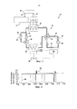
[0014] на Фиг. 1 проиллюстрировано схематическое изображение типовой теплонасосной системы;[0014] in FIG. 1 illustrates a schematic illustration of a typical heat pump system;
[0015] на Фиг. 2 проиллюстрирован график типового потребления энергии цикла теплонасосной системы между нормальным рабочим режимом и режимом автономного размораживания по сравнению со стандартным режимом размораживания;[0015] in FIG. 2 illustrates a graph of typical energy consumption of a heat pump system cycle between a normal operating mode and an autonomous defrost mode compared to a standard defrost mode;
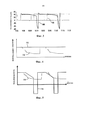
[0016] на Фиг. 3 проиллюстрирован график типовой тепловой мощности цикла теплонасосной системы между нормальным рабочим режимом и режимом автономного размораживания по сравнению со стандартным режимом размораживания;[0016] in FIG. 3 illustrates a graph of a typical heat output of a heat pump system cycle between a normal operating mode and an autonomous defrost mode compared to a standard defrost mode;
[0017] на Фиг. 4 проиллюстрирован график типового потребления энергии цикла теплонасосной системы между нормальным рабочим режимом и режимом бесперебойного размораживания по сравнению со стандартным режимом размораживания; и[0017] in FIG. 4 illustrates a graph of typical energy consumption of a heat pump system cycle between a normal operating mode and a continuous defrost mode compared to a standard defrost mode; and
[0018] на Фиг. 5 проиллюстрирован график типовой тепловой мощности цикла теплонасосной системы между нормальным рабочим режимом и режимом бесперебойного размораживания по сравнению со стандартным режимом размораживания;[0018] in FIG. 5 illustrates a graph of typical heat output of a heat pump system cycle between normal operating mode and uninterrupted defrost mode compared to a standard defrost mode;
ОСУЩЕСТВЛЕНИЕ ИЗОБРЕТЕНИЯDETAILED DESCRIPTION OF THE INVENTION
[0019] В данном документе описаны системы и способы размораживания теплонасосной системы. Теплонасосная система может быть разморожена в режиме «автономного размораживания», режиме «бесперебойного размораживания» или комбинации режима автономного размораживания и режима бесперебойного размораживания без приведения теплонасосной системы в реверсивный цикл.[0019] This document describes systems and methods for defrosting a heat pump system. The heat pump system can be defrosted in the "stand-alone defrost" mode, the "uninterrupted defrost" mode, or a combination of the stand-alone defrost mode and the uninterrupted defrost mode without bringing the heat pump system into a reverse cycle.
[0020] На Фиг. 1 проиллюстрирована типовая теплонасосная система 10, в целом, имеющая контур 12 холодильного агента для кондиционирования флюида, циркулируемого в контуре или контуре 14 теплообмена. В некоторых вариантах реализации изобретения теплонасосная система 10 представляет собой теплонасосную систему с передачей тепла от воздуха к воздуху или с передачей тепла от воздуха к воде.[0020] In FIG. 1 illustrates a typical
[0021] Контур 12 холодильного агента, в целом, содержит один или более компрессоров 20, конденсатор 22, дроссельные устройства 24, 26 и один или более испарителей 28. Конденсатор 22 расположен с возможностью приема холодильного агента высокого давления в парообразном состоянии от компрессора 20 посредством дренажного трубопровода 30. Холодильный реагент в конденсаторе 22 охлаждается при помощи холодной воды, воздуха или т.п. в контуре 14 теплообмена, которая уносит тепло конденсации. Холодильный агент конденсируется в конденсаторе 22, а затем подается на дроссельное устройство 24.[0021] The
[0022] Дроссельное устройство 24 (например, дроссельный вентиль) установлен внутри трубопровода 32 и служит для уменьшения подачи жидкого холодильного агента до низкого давления и для регулировки потока холодильного агента через систему. Вследствие процесса расширения температура и давление холодильного агента снижаются перед его попаданием в испаритель 28.[0022] A throttle device 24 (for example, a throttle valve) is installed inside the
[0023] В испарителе 28 холодильный агент вводится в теплообменную связь с теплообменной средой, такой как циркулируемый наружный окружающий воздух. Холодильный агент при более низком давлении поглощает тепло от теплообменной среды, и холодильный агент последовательно испаряется. Затем пар холодильного агента вытягивается из испарителя 28 посредством впускного трубопровода 34 компрессора и сжимается перед повторным началом цикла.[0023] In the
[0024] В типовом варианте реализации изобретения теплонасосная система 10 содержит реверсивные клапаны 36 и 38, выполненные с возможностью выборочного переключения контура 12 холодильного агента между режимом нагревания и режимом охлаждения. Как проиллюстрировано, реверсивный клапан 36 представляет собой четырехходовой клапан, а реверсивный клапан 38 представляет собой трехходовой клапан. Система 10 может содержать один или более контроллеров 100, запрограммированных на выборочное реверсивное приведение контура 12 холодильного агента в действие между режимом охлаждения и режимом нагревания. Как используется в данном документе, термин «контроллер» относится к специализированной интегральной схеме (ASIC), электронной схеме, процессору (совместно используемому, выделенному или групповому) и памяти, которая выполняет одну или более программ программного или программно-аппаратного обеспечения, комбинационной логической схеме и/или другим подходящим компонентам, которые обеспечивают описанную функциональность. Однако, система 10 может иметь различные другие конфигурации клапанов, которые позволяют системе 10 функционировать, как описано в данном документе. В качестве альтернативы, теплонасосная система 10 может не содержать реверсивные клапаны 36, 38 или реверсивный трубопровод 46 с дроссельным устройством 26.[0024] In an exemplary embodiment, the
[0025] Контур 14 теплообмена обменивает тепловую энергию между конденсатором 22 и обслуживаемым помещением 40 (например, зданием). Контур 14 теплообмена содержит подводящий трубопровод 42, обратный трубопровод 44 и нагнетательный вентилятор или насос (не показан), который подает воздух/воду, нагретые конденсатором 22, в обслуживаемое помещение 40, где вентилятор вытягивает воздух над змеевиком для нагревания пространства, как известно из уровня техники. Охлажденный обратный воздух/вода передается по обратному трубопроводу 44, где он может быть направлен обратно в конденсатор 22. В типичных применениях отопления помещений теплонасосная система имеет такие размеры, чтобы обеспечить здание достаточной тепловой мощностью в некоторых «конструктивных условиях», что представляет собой сложное, но не редкостное состояние температуры наружного воздуха.[0025] The
[0026] Во время работы теплонасосной системы 10 иней может накапливаться на змеевиках испарителя 28. Стандартные способы размораживания включают применение обратного цикла холодильного агента путем активации реверсивных клапанов 36, 38. Однако, такие стандартные способы размораживания могут извлекать тепловую энергию из контура 14 теплообмена, тем самым снижая встроенную производительность теплонасосной системы 10. В отличие от стандартного способа размораживания, типовая теплонасосная система 10 применяет способ «автономного размораживания» и/или «бесперебойного размораживания» для размораживания испарителя 28.[0026] During operation of the
[0027] Способы как «автономного размораживание», так и «бесперебойного размораживания» не реверсируют цикл холодильного агента, а извлекают тепловую энергию, необходимую для размораживания испарителя 28 из наружного воздуха вместо контура 14 теплообмена. Однако, в некоторых вариантах реализации изобретения теплонасосная система 10 может также применять реверсивный цикл в дополнение к способам «автономного размораживания» и «бесперебойного размораживания» при чрезмерном отложении инея на испарителе 28.[0027] Both “stand-alone defrosting” and “uninterrupted defrosting” methods do not reverse the refrigerant cycle, but extract the thermal energy needed to defrost the evaporator 28 from the outside air instead of the
[0028] Способ «автономного размораживания» учитывает ожидаемый цикл (т.е. выключение компрессоров), чтобы соответствовать потреблению тепла помещением 40, и использует наружный окружающий воздух для размораживания. Таким образом, система 10 уменьшает или предотвращает накопление инея без необходимости применения обратного цикла холодильного агента. В способе автономного размораживания испаритель 28 размораживают при обнаружении контроллером 100 заданного уровня или количества (например, небольшого слоя) накопления инея при помощи тепловой энергии наружного воздуха, температура которого выше точки замерзания. Это отличается от некоторых систем предшествующего уровня техники, которые ждут, пока не образуется значительный, толстый слой инея. Путем активации вентилятора(ов) 48 наружного теплообменника и отключения компрессора(ов) 20 можно уменьшить или предотвратить охлаждение контура 14 теплообмена во время цикла размораживания.[0028] The “self-defrosting” method takes into account the expected cycle (ie, turning off the compressors) to match the heat consumption of
[0029] В процессе эксплуатации теплонасосную систему 10 отслеживают на предмет образования инея. Например, один или более датчиков 50 могут быть функционально связаны с испарителем 28 для обнаружения образования инея на змеевиках или других компонентах испарителя 28. Датчик 50 может представлять собой датчик температуры, который улавливает температуру холодильного агента и/или температуру окружающего воздуха. Однако, система 10 может использовать любой подходящий способ обнаружения образования инея на испарителе 28, такой как улавливание давления холодильного агента внутри испарителя, улавливание увеличения перепада давления со стороны воздуха вдоль змеевика испарителя и т.д.[0029] During operation, the
[0030] При температуре окружающего воздуха выше точки замерзания воды (т.е. >0°C на уровне моря) и обнаружении заданного уровня инея на испарителе 28, контроллер 100 отключает компрессор(ы) 20 и активирует вентилятор(ы) 48 наружного теплообменника для нагнетания окружающего воздуха через испаритель 28. Поскольку температура окружающего воздуха выше температуры замерзания, поток воздух начнет растапливать иней, образованный на испарителе 28. В типовом варианте реализации изобретения система 10 обнаруживает начало образования инея (т.е. до полного образования инея), так что системе 10 необходимо только работать в режиме автономного размораживания в течение коротких периодов времени для удаления небольших слоев инея.[0030] When the ambient temperature is above the freezing point of the water (ie> 0 ° C at sea level) and a predetermined frost level is detected on the
[0031] При соответствии заданному требованию уменьшения инея, контроллер 100 обратно включает компрессор(ы) 20, и система 10 работает нормально. В типовом варианте реализации изобретения компрессор(ы) 20 включаются, и цикл размораживания прекращается при достижении заданной температуры холодильного агента на приемлемой точке в змеевике теплообменника. Например, датчик 50 может содержать датчик температуры змеевика для обнаружения повышенной температуры змеевика и сигнальный контроллер 100 для завершения цикла размораживания. В качестве альтернативы, могут быть использованы датчик давления или переключатель давления, или циклы размораживания могут проходить в течение фиксированного промежутка времени. Однако, цикл автономного размораживания может быть закончен при появлении других условий, как, например, когда перепад давления со стороны воздуха вдоль змеевика испарителя становится ниже заданного уровня.[0031] Subject to the predetermined frost reduction requirement, the
[0032] Соответственно, вследствие отключения компрессора(ов) 20 снижается потребление энергии системой 10. Кроме того, поскольку система 10 не работает в реверсивном цикле, конденсатор 22 не используется в качестве испарителя, что в результате приводит к нежелательному охлаждению флюида, циркулируемого внутри контура 14 теплообмена.[0032] Accordingly, by shutting off the compressor (s) 20, the energy consumption of the
[0033] На Фиг. 2 проиллюстрирован график типового потребления энергии цикла теплонасосной системы 10 между нормальным рабочим режимом и режимом автономного размораживания (трубопровод 104) по сравнению с циклом между нормальным рабочим режимом и стандартным режимом размораживания (трубопровод 102), при этом контур 12 холодильного агента работает в реверсивном цикле.[0033] In FIG. 2 illustrates a graph of typical energy consumption of a cycle of a
[0034] На Фиг. 3 проиллюстрирован график типовой тепловой мощности цикла теплонасосной системы 10 между нормальным рабочим режимом и режимом автономного размораживания (трубопровод 106) по сравнению с циклом между нормальным рабочим режимом и стандартным режимом размораживания (трубопровод 108).[0034] FIG. 3 illustrates a graph of typical heat output of a cycle of a
[0035] Способ «бесперебойного размораживания» уменьшает или предотвращает замораживание путем уменьшения мощности теплонасосной системы 10 с учетом ожидаемых требований к уменьшенной тепловой нагрузке помещения 40 и использует наружный окружающий воздух для размораживания. Однако, хотя мощность снижается, способ все же обеспечивает некоторую степень мощности. Таким образом, система 10 снижает скорость компрессора(ов) 20 и/или отключает некоторые компрессоры 20, сохраняя при этом достаточную тепловую мощность для контура 14 теплообмена.[0035] The “uninterrupted defrost” method reduces or prevents freezing by reducing the power of the
[0036] В процессе эксплуатации теплонасосную систему 10 отслеживают на предмет образования инея. Например, датчик 50 может быть функционально связан с испарителем 28 для обнаружения образования инея на змеевиках или других компонентах испарителя 28. Датчик 50 может представлять собой датчик температуры, который улавливает температуру холодильного агента и/или температуру окружающего воздуха. Однако, система 10 может использовать любой подходящий способ обнаружения образования инея на испарителе 28, как описано в данном документе.[0036] During operation, the
[0037] При температуре окружающего воздуха выше точки замерзания воды (т.е. >0°C на уровне моря) и обнаружении заданного небольшого уровня инея на испарителе 28, контроллер 100 снижает скорость компрессоров 20 с изменяющейся скоростью и/или снижает количество работающих компрессоров 20 (в системе с множеством компрессоров). Затем температура змеевика испарителя 28 отслеживается для определения повышения температуры холодильного агента и превышения ею 0°C (или другого заданного значения) после снижения скорости компрессора и/или количества работающих компрессоров.[0037] When the ambient temperature is above the freezing point of the water (ie> 0 ° C at sea level) and a predetermined small level of frost is detected on the
[0038] Если температура превышает, например, 0°C, контроллер 100 поддерживает условия компрессора, и температура змеевика отслеживается для определения стабилизации температуры холодильного агента выше 0°C. В этой операции полученный в результате более теплый змеевик испарителя может быть достаточным для растапливания имеющегося небольшого слоя инея, сохраняя при этом некоторую тепловую мощность для контура 14 теплообмена. В типовом варианте реализации изобретения компрессор(ы) 20 возвращаются к нормальной работе (т.е. работают с нормальной скоростью и/или все компрессоры включаются), и цикл размораживания прекращается при достижении заданной температуры холодильного агента на приемлемой точке в змеевике теплообменника. Например, датчик 50 может содержать датчик температуры змеевика для обнаружения повышенной температуры змеевика и сигнальный контроллер 100 для завершения цикла размораживания. В качестве альтернативы, могут быть использованы датчик давления или переключатель давления, или циклы размораживания могут проходить в течение фиксированного промежутка времени. Однако, цикл автономного размораживания может быть закончен при появлении других условий, как, например, когда перепад давления со стороны воздуха вдоль змеевика испарителя становится ниже заданного уровня.[0038] If the temperature exceeds, for example, 0 ° C, the
[0039] Если в течение заданного времени температура холодильного агента остается ниже или равна 0°C или снижается, система 10 может переключаться в режим автономного размораживания, и компрессоры 20 выключаются, и вентилятор 48 приводится в действие для нагревания змеевика испарителя наружным окружающим воздухом (если его температура выше точки замерзания воды).[0039] If, for a predetermined time, the temperature of the refrigerant remains lower or equal to 0 ° C or decreases, the
[0040] На Фиг. 4 проиллюстрирован график типового потребления энергии цикла теплонасосной системы 10 между нормальным рабочим режимом и режимом бесперебойного размораживания (трубопровод 110) по сравнению с циклом между нормальным рабочим режимом и стандартным режимом размораживания (трубопровод 112), при этом контур 12 холодильного агента работает в реверсивном цикле.[0040] FIG. 4 illustrates a graph of typical energy consumption of a cycle of a
[0041] На Фиг. 5 проиллюстрирован график типовой тепловой мощности цикла теплонасосной системы 10 между нормальным рабочим режимом и режимом бесперебойного размораживания (трубопровод 114) по сравнению с циклом между нормальным рабочим режимом и стандартным режимом размораживания (трубопровод 116).[0041] FIG. 5, a graph of a typical heat output of a cycle of a
[0042] Система 10 может использовать различные конфигурации компрессоров 20. Например, первая конфигурация включает один компрессор с постоянной скоростью, вторая конфигурация включает один компрессор с изменяющейся скоростью, третья конфигурация включает несколько компрессоров с постоянной скоростью, и четвертая конфигурация включает компрессоры с постоянной и изменяющейся скоростью. Система 10 может быть приведена в действие в режиме автономного размораживания для всех четырех конфигураций, и система 10 может быть приведена в действие в режиме бесперебойного размораживания для второй, третьей и четвертой конфигураций.[0042] The
[0043] В данном документе описаны системы и способы размораживания теплонасосной системы. Теплонасосная система может быть разморожена в режиме автономного размораживания, режиме бесперебойного размораживания или режиме автономного и бесперебойного размораживания без приведения теплонасосной системы в реверсивный цикл. Режим автономного размораживания включает выключение компрессоров цикла холодильного агента и приведение в действие вентиляторов для нагнетания окружающего воздуха над замороженным испарителем для размораживания. Режим бесперебойного размораживания включает снижение скорости компрессоров и/или выключение нескольких из всех компрессоров для повышения температуры холодильного агента для размораживания испарителя. Режим автономного и бесперебойного размораживания включает приведение теплонасосной системы в оба режима автономного размораживания и бесперебойного размораживания последовательно или отдельно в любом порядке.[0043] This document describes systems and methods for defrosting a heat pump system. The heat pump system can be defrosted in stand-alone defrost mode, uninterrupted defrost mode or stand-alone and uninterrupted defrost mode without bringing the heat pump system into a reverse cycle. Autonomous defrosting includes turning off the compressors of the refrigerant cycle and activating the fans to pump ambient air over the frozen evaporator for defrosting. The continuous defrost mode includes reducing the speed of the compressors and / or turning off several of all compressors to increase the temperature of the refrigerant to defrost the evaporator. The autonomous and uninterrupted defrost mode includes bringing the heat pump system into both autonomous defrost and uninterrupted defrost modes sequentially or separately in any order.
[0044] Таким образом, коэффициент производительности теплонасосной системы может значительно увеличиваться, с небольшим влиянием или без такого на встроенную тепловую мощность и с небольшими или без каких-либо дополнительных затрат на аппаратное оборудование. В некоторых случаях встроенная тепловая мощность теплонасосной системы может быть улучшена при полной нагрузке, что повышает затраты на подаваемую тепловую мощность. Система повышает коэффициент сезонных изменений производительности (например, на 15%). В дополнение к увеличению коэффициента полезного действия, описанные способы размораживания могут поддерживать стабильность воздушного или водного контура здания, увеличивать надежность блока и снижать время на лабораторные испытания.[0044] Thus, the coefficient of performance of the heat pump system can increase significantly, with little or no effect on the integrated heat output and with little or no additional hardware cost. In some cases, the integrated heat output of the heat pump system can be improved at full load, which increases the cost of the heat input. The system increases the rate of seasonal changes in productivity (for example, by 15%). In addition to increasing the efficiency, the described defrosting methods can maintain the stability of the air or water circuit of the building, increase the reliability of the unit and reduce the time required for laboratory tests.
[0045] Хотя настоящее изобретение подробно описано в связи лишь с ограниченным количеством вариантов реализации изобретения, можно без труда понять, что настоящее изобретение не ограничивается такими раскрытыми вариантами реализации изобретения. Наоборот, настоящее изобретение может быть модифицировано с возможностью включения любого количества вариаций, изменений, замен или эквивалентных расположений, которые прежде не описаны, но соизмеримы с сущностью и объемом настоящего изобретения. Кроме того, в то время как описаны различные варианты реализации изобретения, следует понимать, что аспекты настоящего изобретения могут включать только некоторые из описанных вариантов реализации изобретения. Соответственно, настоящее изобретение следует рассматривать как ограниченное только объемом прилагаемой формулы изобретения, а не вышеприведенным описанием.[0045] Although the present invention has been described in detail in connection with only a limited number of embodiments of the invention, it can be readily understood that the present invention is not limited to such disclosed embodiments of the invention. On the contrary, the present invention can be modified to include any number of variations, changes, substitutions or equivalent arrangements that have not been previously described, but are comparable with the essence and scope of the present invention. In addition, while various embodiments of the invention have been described, it should be understood that aspects of the present invention may include only some of the described embodiments of the invention. Accordingly, the present invention should be construed as limited only by the scope of the attached claims, and not the above description.
Claims (36)
Applications Claiming Priority (1)
| Application Number | Priority Date | Filing Date | Title |
|---|---|---|---|
| PCT/IB2014/002733 WO2016083858A1 (en) | 2014-11-24 | 2014-11-24 | Systems and methods for free and positive defrost |
Publications (1)
| Publication Number | Publication Date |
|---|---|
| RU2672995C1 true RU2672995C1 (en) | 2018-11-21 |
Family
ID=52440708
Family Applications (1)
| Application Number | Title | Priority Date | Filing Date |
|---|---|---|---|
| RU2017117893A RU2672995C1 (en) | 2014-11-24 | 2014-11-24 | System and method of autonomous and uninterrupted defrosting |
Country Status (7)
| Country | Link |
|---|---|
| US (1) | US10823482B2 (en) |
| EP (1) | EP3224554B1 (en) |
| CN (1) | CN107076477B (en) |
| ES (1) | ES2692846T3 (en) |
| RU (1) | RU2672995C1 (en) |
| TR (1) | TR201815100T4 (en) |
| WO (1) | WO2016083858A1 (en) |
Families Citing this family (15)
| Publication number | Priority date | Publication date | Assignee | Title |
|---|---|---|---|---|
| EP3109572B1 (en) * | 2015-06-22 | 2019-05-01 | Lg Electronics Inc. | Refrigerator |
| US11493260B1 (en) * | 2018-05-31 | 2022-11-08 | Thermo Fisher Scientific (Asheville) Llc | Freezers and operating methods using adaptive defrost |
| EP3587963A1 (en) * | 2018-06-22 | 2020-01-01 | Danfoss A/S | A method for initiating defrosting of an evaporator |
| CN108759261B (en) * | 2018-07-18 | 2019-09-27 | 中国人民解放军国防科技大学 | Parallel precooler and deicing method thereof |
| CN111174437B (en) * | 2018-11-13 | 2022-03-04 | 艾欧史密斯(中国)热水器有限公司 | Control method of heat pump water heater |
| US11131497B2 (en) * | 2019-06-18 | 2021-09-28 | Honeywell International Inc. | Method and system for controlling the defrost cycle of a vapor compression system for increased energy efficiency |
| CN110762673A (en) * | 2019-11-06 | 2020-02-07 | 珠海格力电器股份有限公司 | Cold water air conditioning system, anti-freezing control method thereof, storage medium and computer equipment |
| US11221173B2 (en) * | 2019-11-13 | 2022-01-11 | Lineage Logistics, LLC | Controlled defrost for chilled environments |
| DE102020107006A1 (en) * | 2020-03-13 | 2021-09-16 | Volkswagen Aktiengesellschaft | Method for operating a heat pump of a motor vehicle and a heat pump |
| DE102020112376A1 (en) * | 2020-05-07 | 2021-11-11 | Wolf Gmbh | Heat pump system |
| US11466910B2 (en) | 2020-05-11 | 2022-10-11 | Rheem Manufacturing Company | Systems and methods for reducing frost accumulation on heat pump evaporator coils |
| CN111964300B (en) * | 2020-08-17 | 2021-11-30 | 广东美的暖通设备有限公司 | Control method and device of air source heat pump equipment, equipment and readable storage medium |
| US11709004B2 (en) * | 2020-12-16 | 2023-07-25 | Lennox Industries Inc. | Method and a system for preventing a freeze event using refrigerant temperature |
| CN113587530B (en) * | 2021-08-12 | 2023-04-14 | 澳蓝(福建)实业有限公司 | Defrosting method for indirect evaporation heat exchange core body of data center |
| CN115574487B (en) * | 2022-10-08 | 2023-06-23 | 中国建筑西南设计研究院有限公司 | Performance evaluation method for air source heat pump heating system under defrosting working condition |
Citations (6)
| Publication number | Priority date | Publication date | Assignee | Title |
|---|---|---|---|---|
| WO2009158612A2 (en) * | 2008-06-27 | 2009-12-30 | Carrier Corporation | Hot gas defrost process |
| EP2402686A1 (en) * | 2009-02-24 | 2012-01-04 | Daikin Industries, Ltd. | Heat pump system |
| RU2480684C2 (en) * | 2007-06-29 | 2013-04-27 | Электролюкс Хоум Продактс, Инк. | Method and device for defrosting with hot steam |
| JP2014013122A (en) * | 2012-07-05 | 2014-01-23 | Panasonic Corp | Refrigeration cycle device and hot water generation device provided with the same |
| WO2014098724A1 (en) * | 2012-12-21 | 2014-06-26 | Fläkt Woods AB | Method and apparatus for defrosting of an evaporator in connection with an air handling unit |
| EP2784414A1 (en) * | 2011-11-24 | 2014-10-01 | Mitsubishi Heavy Industries, Ltd. | Defrosting operation method for heat pump system, and heat pump system |
Family Cites Families (27)
| Publication number | Priority date | Publication date | Assignee | Title |
|---|---|---|---|---|
| US4122687A (en) | 1976-12-09 | 1978-10-31 | Mckee Thomas M | Refrigeration system with low energy defrost |
| US4086779A (en) | 1977-01-25 | 1978-05-02 | Lewis Roswell E | Refrigeration defrosting |
| US4295340A (en) | 1979-02-14 | 1981-10-20 | Tyler Refrigeration Corporation | Refrigerated display case having ambient air defrost |
| US4375155A (en) | 1981-12-24 | 1983-03-01 | Emhart Industries, Inc. | Reach-in refrigerated display case with ambient air defrost |
| US4951473A (en) | 1988-10-12 | 1990-08-28 | Honeywell, Inc. | Heat pump defrosting operation |
| US5533357A (en) * | 1995-02-15 | 1996-07-09 | Carrier Corporation | Air conditioning apparatus |
| US5927083A (en) * | 1998-03-09 | 1999-07-27 | Carrier Corporation | Compressor cycle dependent defrost control |
| US6490876B2 (en) * | 2000-02-15 | 2002-12-10 | Whirlpool Corporation | Method and apparatus for de-icing dehumidifier |
| NZ503106A (en) | 2000-02-28 | 2002-07-26 | Fisher & Paykel Appliances Ltd | Refrigerator with at least a fresh food compartment and evaporator operating within 10 degrees centigrade below compartment temperature, so that air at above 0 degrees is blown over evaporator during off cycle |
| US6334321B1 (en) | 2000-03-15 | 2002-01-01 | Carrier Corporation | Method and system for defrost control on reversible heat pumps |
| JP3932913B2 (en) | 2002-01-29 | 2007-06-20 | ダイキン工業株式会社 | Heat pump water heater |
| GB2405360B (en) | 2003-08-27 | 2007-02-07 | Ebac Ltd | Dehumidifiers |
| US9068771B2 (en) | 2006-01-20 | 2015-06-30 | Carrier Corporation | Method for automatically adjusting the defrost interval in a heat pump system |
| KR100798781B1 (en) | 2006-10-26 | 2008-01-29 | 삼성전자주식회사 | Method for controlling operation of air conditioner |
| JP5121844B2 (en) * | 2007-10-09 | 2013-01-16 | パナソニック株式会社 | Refrigeration cycle equipment |
| CN101782305B (en) * | 2009-01-15 | 2013-03-06 | 珠海格力电器股份有限公司 | Heat-pump type air-conditioning device and defrosting method thereof |
| EP2505941B1 (en) | 2009-11-25 | 2019-05-15 | Daikin Industries, Ltd. | Refrigeration device for container |
| JP2012048700A (en) * | 2010-07-29 | 2012-03-08 | Sony Corp | Information processing unit |
| JP2012057869A (en) | 2010-09-09 | 2012-03-22 | Panasonic Corp | Air conditioner |
| KR20120092442A (en) | 2011-02-11 | 2012-08-21 | 삼성전자주식회사 | Refrigerator |
| US8528946B2 (en) * | 2011-06-28 | 2013-09-10 | I-Tek Metal Mfg. Co., Ltd. | Door lock with idle travel in a locking state |
| US9970696B2 (en) | 2011-07-20 | 2018-05-15 | Thermo King Corporation | Defrost for transcritical vapor compression system |
| DK2757335T3 (en) | 2011-09-14 | 2018-11-12 | Hefei Midea Refrigerator Co | Refrigerator with defrost and control method |
| KR101953120B1 (en) | 2012-08-27 | 2019-03-04 | 삼성전자주식회사 | Cooling apparatus and controlling method thereof |
| US8997507B2 (en) | 2012-10-22 | 2015-04-07 | Whirlpool Corporation | Low energy evaporator defrost |
| US9175888B2 (en) | 2012-12-03 | 2015-11-03 | Whirlpool Corporation | Low energy refrigerator heat source |
| KR101982776B1 (en) | 2012-12-10 | 2019-05-27 | 엘지전자 주식회사 | Refrigerator, and nethod for operating the same |
-
2014
- 2014-11-24 TR TR2018/15100T patent/TR201815100T4/en unknown
- 2014-11-24 CN CN201480083611.5A patent/CN107076477B/en active Active
- 2014-11-24 RU RU2017117893A patent/RU2672995C1/en active
- 2014-11-24 ES ES14833359.4T patent/ES2692846T3/en active Active
- 2014-11-24 US US15/528,681 patent/US10823482B2/en active Active
- 2014-11-24 EP EP14833359.4A patent/EP3224554B1/en active Active
- 2014-11-24 WO PCT/IB2014/002733 patent/WO2016083858A1/en active Application Filing
Patent Citations (6)
| Publication number | Priority date | Publication date | Assignee | Title |
|---|---|---|---|---|
| RU2480684C2 (en) * | 2007-06-29 | 2013-04-27 | Электролюкс Хоум Продактс, Инк. | Method and device for defrosting with hot steam |
| WO2009158612A2 (en) * | 2008-06-27 | 2009-12-30 | Carrier Corporation | Hot gas defrost process |
| EP2402686A1 (en) * | 2009-02-24 | 2012-01-04 | Daikin Industries, Ltd. | Heat pump system |
| EP2784414A1 (en) * | 2011-11-24 | 2014-10-01 | Mitsubishi Heavy Industries, Ltd. | Defrosting operation method for heat pump system, and heat pump system |
| JP2014013122A (en) * | 2012-07-05 | 2014-01-23 | Panasonic Corp | Refrigeration cycle device and hot water generation device provided with the same |
| WO2014098724A1 (en) * | 2012-12-21 | 2014-06-26 | Fläkt Woods AB | Method and apparatus for defrosting of an evaporator in connection with an air handling unit |
Also Published As
| Publication number | Publication date |
|---|---|
| US10823482B2 (en) | 2020-11-03 |
| EP3224554B1 (en) | 2018-10-03 |
| US20170276422A1 (en) | 2017-09-28 |
| WO2016083858A1 (en) | 2016-06-02 |
| TR201815100T4 (en) | 2018-11-21 |
| CN107076477B (en) | 2021-04-27 |
| EP3224554A1 (en) | 2017-10-04 |
| ES2692846T3 (en) | 2018-12-05 |
| CN107076477A (en) | 2017-08-18 |
Similar Documents
| Publication | Publication Date | Title |
|---|---|---|
| RU2672995C1 (en) | System and method of autonomous and uninterrupted defrosting | |
| JP5575192B2 (en) | Dual refrigeration equipment | |
| RU2638704C2 (en) | Method and device for defrosting evaporator relating to for air conditioning unit | |
| EP2592367A2 (en) | Refrigeration cycle apparatus and hot water producing apparatus | |
| EP3650769B1 (en) | Heat exchange unit for air conditioning device and air conditioning device | |
| JP5095295B2 (en) | Water heater | |
| JP2012207803A (en) | Control method of air conditioner | |
| JP2007315702A (en) | Freezer | |
| JP2014031981A (en) | Binary refrigeration device | |
| JP6887979B2 (en) | Refrigerant leakage determination device, refrigeration device equipped with this refrigerant leakage determination device, and refrigerant leakage determination method | |
| WO2018210119A1 (en) | Control method and device for air conditioner | |
| JPWO2017149664A1 (en) | refrigerator | |
| JP2013119954A (en) | Heat pump hot water heater | |
| JP5501279B2 (en) | HEAT PUMP SYSTEM AND HEAT PUMP SYSTEM CONTROL METHOD | |
| US6263686B1 (en) | Defrost control method and apparatus | |
| EP2204620B1 (en) | Heating and/or cooling installation and method for monitoring the operability of the installation | |
| US11262114B2 (en) | System for deicing an external evaporator for heat pump systems | |
| JPH04251158A (en) | Operation control device for refrigerating device | |
| JPH08247561A (en) | Air conditioner | |
| JP6715655B2 (en) | Cooling system | |
| JP6926046B2 (en) | Abnormality judgment device, refrigerating device equipped with this abnormality judgment device, and abnormality judgment method of compressor | |
| JP5516332B2 (en) | Heat pump type hot water heater | |
| US11047610B2 (en) | Defrost cycle control assembly in a heat pump | |
| JP2004271102A (en) | Heat pump water heater | |
| CN111664556A (en) | Oil temperature heating belt control method and device of heat pump air conditioner and heat pump air conditioner |