JP5501279B2 - HEAT PUMP SYSTEM AND HEAT PUMP SYSTEM CONTROL METHOD - Google Patents
HEAT PUMP SYSTEM AND HEAT PUMP SYSTEM CONTROL METHOD Download PDFInfo
- Publication number
- JP5501279B2 JP5501279B2 JP2011078501A JP2011078501A JP5501279B2 JP 5501279 B2 JP5501279 B2 JP 5501279B2 JP 2011078501 A JP2011078501 A JP 2011078501A JP 2011078501 A JP2011078501 A JP 2011078501A JP 5501279 B2 JP5501279 B2 JP 5501279B2
- Authority
- JP
- Japan
- Prior art keywords
- heat exchanger
- heater
- flow rate
- refrigerant
- temperature
- Prior art date
- Legal status (The legal status is an assumption and is not a legal conclusion. Google has not performed a legal analysis and makes no representation as to the accuracy of the status listed.)
- Expired - Fee Related
Links
Images


Description
この発明は、冷媒と水等の流体とを熱交換させる熱交換器の凍結防止技術に関する。 The present invention relates to a freeze prevention technique for a heat exchanger that exchanges heat between a refrigerant and a fluid such as water.
ヒートポンプユニットで高温の冷媒と水とを熱交換させて温水を生成し、生成した温水をパネルヒータ等へ供給することにより、暖房運転を行うヒートポンプ式の暖房システムがある。
この暖房システムでは、暖房運転を行うと、外気と冷媒とを熱交換させる熱交換器へ低温の冷媒が供給されるため、外気と冷媒とを熱交換させる熱交換器に霜が付着することがある。熱交換器に霜が付着した場合、付着した霜を取り除く除霜運転が実行される。除霜運転では、一般的に、冷媒の循環方向を暖房運転時とは逆にして、外気と冷媒とを熱交換させる熱交換器へ高温の冷媒を供給する。
There is a heat pump heating system that performs a heating operation by generating hot water by exchanging heat between high-temperature refrigerant and water in a heat pump unit and supplying the generated hot water to a panel heater or the like.
In this heating system, when heating operation is performed, low-temperature refrigerant is supplied to the heat exchanger that exchanges heat between the outside air and the refrigerant, so that frost may adhere to the heat exchanger that exchanges heat between the outside air and the refrigerant. is there. When frost adheres to the heat exchanger, a defrosting operation is performed to remove the attached frost. In the defrosting operation, generally, a high-temperature refrigerant is supplied to a heat exchanger that exchanges heat between the outside air and the refrigerant by reversing the refrigerant circulation direction from that in the heating operation.
除霜運転を行うと、冷媒と水とを熱交換させる熱交換器へ低温の冷媒が供給されるため、冷媒と水とを熱交換させる熱交換器内で水が凍結することがある。熱交換器内で水が凍結すると、凍結による水の体積膨張により熱交換器が破損することがある。
この発明は、除霜運転時に、冷媒と水とを熱交換させる熱交換器内における水の凍結を防止することを目的とする。
When the defrosting operation is performed, since the low-temperature refrigerant is supplied to the heat exchanger that exchanges heat between the refrigerant and water, water may freeze in the heat exchanger that exchanges heat between the refrigerant and water. When water freezes in the heat exchanger, the heat exchanger may be damaged due to volume expansion of the water due to freezing.
An object of the present invention is to prevent freezing of water in a heat exchanger that exchanges heat between refrigerant and water during a defrosting operation.
この発明に係るヒートポンプシステムは、
圧縮機と、第1熱交換器と、膨張機構と、第2熱交換器とが順次配管により接続され、冷媒が循環する環状の冷媒回路であって、前記冷媒が前記圧縮機、前記第1熱交換器、前記膨張機構、前記第2熱交換器の順に循環する第1循環方向と、前記冷媒が前記圧縮機、前記第2熱交換器、前記膨張機構、前記第1熱交換器の順に循環する第2循環方向とに前記冷媒の循環方向を切り替える切替機構が設けられた冷媒回路と、
ヒータと、放熱器と、前記冷媒回路に接続された前記第1熱交換器とが順次配管により接続され、所定の流体が循環する環状の流体回路と、
前記第1循環方向に冷媒を循環させて、前記冷媒と前記流体回路を循環する前記流体とを前記第1熱交換器において熱交換させて前記流体を加熱する加熱運転と、前記第2循環方向に冷媒を循環させて、前記第2熱交換器に付着した霜を取り除く除霜運転とを、前記切替機構を制御することにより切り替えて実行する運転制御部と、
前記流体回路を循環する流体の流量を計測する流量計測部と、
前記運転制御部が除霜運転を実行する際、前記流量計測部が計測した流量が予め設定された流量閾値より少ない場合には、前記ヒータを運転させて前記流体を加熱するヒータ制御部と
を備えることを特徴とする。
The heat pump system according to the present invention is:
A compressor, a first heat exchanger, an expansion mechanism, and a second heat exchanger are sequentially connected by piping, and are annular refrigerant circuits in which refrigerant circulates, wherein the refrigerant is the compressor, the first A first circulation direction in which the heat exchanger, the expansion mechanism, and the second heat exchanger are circulated in this order, and the refrigerant is in the order of the compressor, the second heat exchanger, the expansion mechanism, and the first heat exchanger. A refrigerant circuit provided with a switching mechanism for switching a circulation direction of the refrigerant to a second circulation direction to circulate;
An annular fluid circuit in which a heater, a radiator, and the first heat exchanger connected to the refrigerant circuit are sequentially connected by piping and a predetermined fluid circulates;
A heating operation in which a refrigerant is circulated in the first circulation direction, heat is exchanged in the first heat exchanger to heat the fluid in the first heat exchanger, and the second circulation direction. An operation control unit that circulates the refrigerant and removes frost adhering to the second heat exchanger by switching the defrosting operation by controlling the switching mechanism;
A flow rate measuring unit for measuring a flow rate of the fluid circulating in the fluid circuit;
When the flow rate measured by the flow rate measurement unit is less than a preset flow rate threshold value when the operation control unit performs the defrosting operation, a heater control unit that operates the heater and heats the fluid; It is characterized by providing.
この発明に係るヒートポンプシステムでは、除霜運転時に、流体回路を循環する水等の流体の流量が少ない場合には、ヒータにより流体を加熱する。そのため、除霜運転時に、第1熱交換器内における流体の凍結を防止することができる。 In the heat pump system according to the present invention, when the flow rate of a fluid such as water circulating in the fluid circuit is small during the defrosting operation, the fluid is heated by the heater. Therefore, the fluid in the first heat exchanger can be prevented from freezing during the defrosting operation.
実施の形態1.
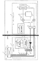
図1は、実施の形態1に係るヒートポンプシステム1の構成図である。
ヒートポンプシステム1は、室内に設置される室内ユニット2と、室外に設置されるヒートポンプユニット3とを備える。また、ヒートポンプシステム1は、室内ユニット2と配管で接続された放熱器11を備える。放熱器11は、例えば、パネルヒータや床暖房パネル等である。
FIG. 1 is a configuration diagram of a
The
室内ユニット2は、ヒートポンプユニット3が備える熱交換器33(第1熱交換器)と、ポンプ21と、ヒータ22と、放熱器11とを順次配管で接続し、水(流体)が循環する水回路23(流体回路)を備える。水回路23には、ヒータ22へ流入する水の温度を流入温度(ヒータ流入温度)として計測する温度センサ24と、ヒータ22から流出した水の温度を流出温度(ヒータ流出温度)として計測する温度センサ25とが設けられている。
また、室内ユニット2は、マイコンなどにより構成される制御装置である流量測定部26及びヒータ制御部27を備える。流量測定部26は、温度センサ24が計測した流入温度と、温度センサ25が計測した流出温度とから、水回路23を循環する水の流量を計算により測定する。また、ヒータ制御部27は、流量測定部26が計測した流量等に基づき、ヒータ22のオン/オフを制御する。
The
The
ヒートポンプユニット3は、圧縮機31と、四方弁32(切替機構)と、熱交換器33と、膨張機構34と、熱交換器35(第2熱交換器)とを順次配管で接続し、冷媒が循環する冷媒回路36を備える。冷媒回路36には、熱交換器35の近傍にファン37が設けられる。なお、熱交換器33は、例えば、多数のプレートが積層されて構成されるプレート式熱交換器である。
また、ヒートポンプユニット3は、マイコンなどにより構成される制御装置である運転制御部38を備える。運転制御部38は、四方弁32を制御することにより、冷媒の循環方向を切り替えて、暖房運転と除霜運転とを切り替えて実行する。
The
The
図2は、暖房運転時における冷媒及び水の流れを示す図である。なお、図2において、実線の矢印が冷媒の流れを示し、破線の矢印が水の流れを示す。
暖房運転時には、四方弁32が図1の実線の流路に設定される。したがって、圧縮機31から吐出された高温高圧のガス冷媒が熱交換器33へ流れる。熱交換器33では、高温高圧のガス冷媒と水回路23を循環する水とが熱交換される。その結果、水は加熱され、ガス冷媒は高圧の液冷媒になる。高圧の液冷媒は、膨張機構34で膨張して低圧の液冷媒になり、熱交換器35へ流れる。熱交換器35では、低圧の液冷媒とファン37により供給される外気とが熱交換される。その結果、低圧の液冷媒は低圧のガス冷媒となる。そして、低圧のガス冷媒は、再び圧縮機31に吸入され、高温高圧のガス冷媒となり吐出される。
一方、熱交換器33で加熱された水は、ポンプ21によりヒータ22を通って、放熱器11へ流れる。放熱器11において、水は室内空気へ放熱して冷却され、再び熱交換器33へ流れる。なお、熱交換器33で十分に水が加熱されていない場合には、ヒータ制御部27によりヒータ22がオンされ、所定の温度まで温水が加熱される。
FIG. 2 is a diagram illustrating the flow of refrigerant and water during heating operation. In FIG. 2, the solid arrow indicates the refrigerant flow, and the broken arrow indicates the water flow.
At the time of heating operation, the four-
On the other hand, the water heated by the
暖房運転時に、熱交換器35へ流れる液冷媒の温度が0℃以下であると、外気中の水分が凍結して霜として熱交換器35に付着する。熱交換器35に霜が付着すると、熱交換器35の熱交換面積の減少等により熱交換効率が悪くなり、性能が低下してしまう。
そこで、運転制御部38は、熱交換器35に霜が付着したことを検知すると、四方弁32を制御して、暖房運転から除霜運転に切り替える。なお、熱交換器35に霜が付着したことを検知する方法はどのような方法であってもよい。
When the temperature of the liquid refrigerant flowing to the
Therefore, when detecting that frost has adhered to the
図3は、除霜運転時における冷媒及び水の流れを示す図である。なお、図3において、実線の矢印が冷媒の流れを示し、破線の矢印が水の流れを示す。
除霜運転時には、四方弁32が図1の破線の流路に設定される。したがって、圧縮機31から吐出された高温高圧のガス冷媒が熱交換器35へ流れる。熱交換器35では、高温高圧のガス冷媒とファン37により供給される外気とが熱交換される。この際、高温高圧のガス冷媒により、熱交換器35に付着した霜が溶かされ、霜が取り除かれる。熱交換器35から流出した高圧の液冷媒は、膨張機構34で膨張して低圧の液冷媒になり、熱交換器33へ流れる。熱交換器33では、低圧の液冷媒と水回路23を循環する水とが熱交換される。その結果、低圧の液冷媒は低圧のガス冷媒となる。そして、低圧のガス冷媒は、再び圧縮機31に吸入され、高温高圧のガス冷媒となり吐出される。
一方、熱交換器33で冷却された水は、ポンプ21によりヒータ22を通って、放熱器11へ流れ、再び熱交換器33へ流れる。
FIG. 3 is a diagram illustrating the flow of the refrigerant and water during the defrosting operation. In FIG. 3, the solid arrow indicates the refrigerant flow, and the broken arrow indicates the water flow.
At the time of the defrosting operation, the four-
On the other hand, the water cooled by the
除霜運転時に、熱交換器33へ流れる液冷媒の温度が0℃以下であると、水回路23を循環する水が、熱交換器33内で凍結してしまう虞がある。熱交換器33がプレート式熱交換器である場合等には、熱交換器33内で水が凍結すると、凍結による水の体積膨張により熱交換器33が破損する虞がある。
水回路23を循環する水が、熱交換器33内で凍結してしまうのは、水回路23を循環する水の流量が所定の量(以下の流量閾値Qt)以下であり、かつ、熱交換器33へ流入する水の温度が所定の温度以下の場合である。そこで、以下のように、ヒータ制御部27は、除霜運転時に水回路23を循環する水の流量に応じてヒータ22を制御することにより、熱交換器33内で水が凍結することを防止する。
If the temperature of the liquid refrigerant flowing to the
The water circulating in the
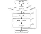
図4は、実施の形態1に係る除霜運転時におけるヒータ制御部27の処理を示すフローチャートである。なお、ヒータ制御部27は、暖房運転から除霜運転に切り替えたことを示す霜取開始信号を運転制御部38から受信すると、図4に示す動作を開始する。
FIG. 4 is a flowchart showing processing of the
ヒータ制御部27は、流量測定部26により測定される、水回路23を循環する水の流量Qが、予め設定された流量閾値Qtより少ないか否かを判定する(S11)。なお、流量閾値Qtは、熱交換器33で冷媒が水から奪う熱量に応じて設定されるものであり、ヒートポンプユニット3の能力によって決定されるものである。したがって、流量閾値Qtは、ヒートポンプユニット3の出荷時等にヒートポンプユニット3の能力に応じた値が設定されている。
The
ヒータ制御部27は、流量Qが流量閾値Qtより少ない場合(S11でYES)、ヒータ制御部27はヒータ22をオンして、水を加熱する(S12)。これにより、熱交換器33へ流入する水の温度が高くなり、熱交換器33内で水が凍結することを防止できる。そして、ヒータ制御部27は、除霜運転から暖房運転に切り替えたことを示す霜取終了信号を運転制御部38から受信すると(S13)、ヒータ22をオフして(S14)、処理を終了する。
一方、ヒータ制御部27は、流量Qが流量閾値Qt以上の場合(S11でNO)、処理を終了する。
When the flow rate Q is smaller than the flow rate threshold value Qt (YES in S11), the
On the other hand, when the flow rate Q is equal to or higher than the flow rate threshold value Qt (NO in S11), the
図5は、流量測定部26が水回路23を循環する水の流量Qを計測する処理を示すフローチャートである。なお、流量測定部26は、暖房運転時にヒータ制御部27によりヒータ22がオンされ、ヒータ22が運転を開始すると動作を開始する。
FIG. 5 is a flowchart showing a process in which the flow
流量測定部26は、所定の時間毎に、温度センサ24が計測した流入温度と、温度センサ25が計測した流出温度とを比較し、流入温度と流出温度との温度差の変化が一定以下か否かを判定する(S21)。例えば、流量測定部26は、以下の式(1)を満たすか否かを判定することにより、温度差の変化が一定以下か否かを判定する。
<式(1)>
|ΔTw,n+1−ΔTw,n|<δ
ここで、ΔTwは、温度差Two−Twiである。Twoは流出温度であり、Twiは流入温度である。添え字n+1は最新の温度計測時刻であり、添え字nは最新時刻の温度計測時刻の所定時間前の時刻である。δは、予め設定された値である。
The flow
<Formula (1)>
| ΔT w, n + 1 −ΔT w, n | <δ
Here, ΔT w is the temperature difference T wo -T wi. T wo is the outflow temperature and T wi is the inflow temperature. The subscript n + 1 is the latest temperature measurement time, and the subscript n is a time that is a predetermined time before the latest temperature measurement time. δ is a preset value.
温度差の変化が一定以下の場合(S21でYES)、流量測定部26は、最新の温度計測時刻における温度差ΔTwと、最新の温度計測時刻におけるヒータ22の消費電力値qhと、水の熱容量Mとを用いて、式(2)に基づき、循環する水の流量Qを計算する(S22)。
<式(2)>
Q=qh/(M・ΔTw)
一方、温度差の変化が一定以上の場合(S21でNO)、所定時間後に再びS21の判定を実施する。
If the change in the temperature difference is greater than a certain value (in S21 YES), the flow
<Formula (2)>
Q = qh / (M · ΔT w )
On the other hand, if the change in temperature difference is equal to or greater than a certain value (NO in S21), the determination in S21 is performed again after a predetermined time.
S22で計算された流量Qはメモリ等に記憶される。そして、S11でヒータ制御部27は、メモリに記憶された最新の流量Qを読み出し、流量Qが流量閾値Qtより少ないか否か判定する。
The flow rate Q calculated in S22 is stored in a memory or the like. In step S11, the
以上のように、実施の形態1に係るヒートポンプシステム1では、除霜運転時に、水回路23を循環する水の流量に応じて、ヒータ22のオン/オフの制御をする。これにより、熱交換器33内で水が凍結することを防止できる。また、除霜運転時におけるヒータ22の運転時間を適切に制御でき、省エネルギー化することができる。
As described above, in the
また、実施の形態1に係るヒートポンプシステム1では、水回路23を循環する水の流量を、流量センサを用いることなく、ヒータ22の出入口の水の温度から計算している。そのため、流量センサを設けるコストや、流量センサの故障等に伴うメンテナンスの手間や、流量センサの設置スペース等を低減することができる。
なお、ポンプ21は定速ポンプである場合、原則として流量Qはほとんど変化しない。したがって、S11の判定時点における流量Qを計測しなくても、メモリに記憶された最新の流量Qを用いてS11の判定を行えば十分である。しかし、例えば、放熱器11として複数のパネルヒータが設けられている場合に、季節の移り変わりに応じてパネルヒータの弁を開閉制御された場合には、流量Qが大きく変化してしまう。そのため、できるだけ直近の流量Qを用いてS11の判定を行うことが望ましい。
また、ポンプ21としてインバータポンプ等の可変ポンプを用いた場合、ポンプ21の制御に応じて流量Qが変化する。そのため、できるだけ直近の流量Qを用いてS11の判定を行うことが望ましい。
もちろん、計算により流量Qを計測する代わりに、水回路23に流量センサを設けて、S11の判定時点における流量Qを計測するようにしてもよい。
In the
When the
When a variable pump such as an inverter pump is used as the
Of course, instead of measuring the flow rate Q by calculation, a flow rate sensor may be provided in the
実施の形態2.
実施の形態2では、流量Qだけでなく、循環する水の温度も用いて、ヒータ22を制御する方法について説明する。
なお、実施の形態2に係るヒートポンプシステム1について、実施の形態1に係るヒートポンプシステム1と異なる部分を説明する。
In the second embodiment, a method for controlling the
In addition, about the
図6は、実施の形態2に係る除霜運転時におけるヒータ制御部27の処理を示すフローチャートである。なお、ヒータ制御部27は、暖房運転から除霜運転に切り替えたことを示す霜取開始信号を運転制御部38から受信すると、図6に示す動作を開始する。
FIG. 6 is a flowchart illustrating processing of the
ヒータ制御部27は、水回路23を循環する水の流量Qが、予め設定された流量閾値Qtより少ないか否かと、温度センサ25が計測した流出温度Twoが予め設定された温度閾値Twtより低いか否かとを判定する(S31)。なお、流量閾値Qtと流出温度Twoとは、熱交換器33で冷媒が水から奪う熱量に応じて設定されるものであり、ヒートポンプユニット3の能力によって決定されるものである。したがって、流量閾値Qtと流出温度Twoとは、ヒートポンプユニット3の出荷時等にヒートポンプユニット3の能力に応じた値が設定されている。
The
ヒータ制御部27は、流量Qが流量閾値Qtより少なく、かつ、流出温度Twoが温度閾値Twtより低い場合(S31でYES)、ヒータ制御部27はヒータ22をオンして、水を加熱する(S32)。これにより、熱交換器33へ流入する水の温度が高くなり、熱交換器33内で水が凍結することを防止できる。そして、ヒータ制御部27は、除霜運転から暖房運転に切り替えたことを示す霜取終了信号を運転制御部38から受信すると(S33)、ヒータ22をオフして(S34)、処理を終了する。
一方、ヒータ制御部27は、流量Qが流量閾値Qt以上の場合と、流出温度Twoが温度閾値Twt以上の場合とのいずれかの場合(S31でNO)、処理を終了する。
On the other hand, the
以上のように、実施の形態2に係るヒートポンプシステム1では、除霜運転時に、水回路23を循環する水の流量だけでなく、水回路23を循環する水の温度に応じて、ヒータ22のオン/オフの制御をする。これにより、実施の形態1に係るヒートポンプシステム1よりも、除霜運転時におけるヒータ22の運転時間を適切に制御でき、省エネルギー化することができる。
As described above, in the
なお、上記説明では、流出温度TwoをS31の判定で使用した。しかし、例えば、熱交換器33へ流入する水の温度を熱交換器流入温度として計測する温度センサを設け、熱交換器流入温度をS31の判定で使用してもよい。
In the above description, the outflow temperature Two is used in the determination of S31. However, for example, a temperature sensor that measures the temperature of water flowing into the
実施の形態3.
実施の形態1,2では、除霜運転時に一旦ヒータ22をオンすると、除霜運転が終了するまでヒータ22をオンしたままであった。実施の形態3では、除霜運転時に所定の時間毎にヒータ22のオン/オフ制御を行う方法について説明する。
なお、実施の形態3に係るヒートポンプシステム1について、実施の形態2に係るヒートポンプシステム1と異なる部分を説明する。
In
In addition, about the
図7は、実施の形態3に係る除霜運転時におけるヒータ制御部27の処理を示すフローチャートである。なお、ヒータ制御部27は、暖房運転から除霜運転に切り替えたことを示す霜取開始信号を運転制御部38から受信すると、図7に示す動作を開始する。
FIG. 7 is a flowchart showing processing of the
ヒータ制御部27は、水回路23を循環する水の流量Qが、予め設定された流量閾値Qtより少ないか否かと、温度センサ25が計測した流出温度Twoが予め設定された温度閾値Twtより低いか否かとを判定する(S41)。
The
ヒータ制御部27は、流量Qが流量閾値Qtより少なく、かつ、流出温度Twoが温度閾値Twtより低い場合(S41でYES)、ヒータ制御部27はヒータ22をオンして、水を加熱する(S42)。これにより、熱交換器33へ流入する水の温度が高くなり、熱交換器33内で水が凍結することを防止できる。
そして、ヒータ制御部27は、除霜運転から暖房運転に切り替えたことを示す霜取終了信号を運転制御部38から受信したか否かを判定する(S43)。ヒータ制御部27は、霜取終了信号を受信した場合(S43でYES)、ヒータ22をオフして(S44)、処理を終了する。一方、ヒータ制御部27は、霜取終了信号を受信していない場合(S43でNO)、処理をS41に戻し、所定の時間後に再び流量Qと流出温度Twoとについての判定を行う。
Then, the
一方、ヒータ制御部27は、流量Qが流量閾値Qt以上の場合と、流出温度Twoが温度閾値Twt以上の場合とのいずれかの場合(S41でNO)、ヒータ22をオフする(S45)。
そして、ヒータ制御部27は、除霜運転から暖房運転に切り替えたことを示す霜取終了信号を運転制御部38から受信したか否かを判定する(S46)。ヒータ制御部27は、霜取終了信号を受信した場合(S46でYES)、処理を終了する。一方、ヒータ制御部27は、霜取終了信号を受信していない場合(S46でNO)、処理をS41に戻し、所定の時間後に再び流量Qと流出温度Twoとについての判定を行う。
On the other hand, the
Then, the
以上のように、実施の形態3に係るヒートポンプシステム1では、除霜運転時に、所定の時間毎にヒータ22のオン/オフの制御をする。これにより、実施の形態1,2に係るヒートポンプシステム1よりも、除霜運転時におけるヒータ22の運転時間を適切に制御でき、省エネルギー化することができる。
As described above, in the
なお、上記説明では、ヒートポンプシステム1がヒートポンプ式の暖房システムであるとした。しかし、ヒートポンプシステム1としては、暖房システムに限らず、ヒートポンプ式の給湯システムや、ヒートポンプ式の暖房給湯システムであってもよい。
ヒートポンプシステム1がヒートポンプ式の給湯システムである場合には、上述したヒートポンプシステム1における放熱器11を給湯タンク内の水へ放熱する放熱器とすればよい。また、ヒートポンプシステム1がヒートポンプ式の暖房給湯システムである場合には、上述したヒートポンプシステム1における水回路23を、熱交換器33と温度センサ24の間から分岐させて、給湯タンク内の水へ放熱する放熱器を接続すればよい。
In the above description, the
When the
また、上記説明では、熱交換器33で冷媒によって加熱される流体が水であるとした。しかし、熱交換器33で冷媒によって加熱される流体は、水に限らず、除霜運転時に凍結する虞のある流体であれば他の流体でも構わない。
In the above description, the fluid heated by the refrigerant in the
1 ヒートポンプシステム、2 室内ユニット、3 ヒートポンプユニット、11 放熱器、21 ポンプ、22 ヒータ、23 水回路、24,25 温度センサ、26 流量測定部、27 ヒータ制御部、31 圧縮機、32 四方弁、33 熱交換器、34 膨張機構、35 熱交換器、36 冷媒回路、37 ファン、38 運転制御部。
DESCRIPTION OF
Claims (5)
ヒータと、放熱器と、前記冷媒回路に接続された前記第1熱交換器とが順次配管により接続され、所定の流体が循環する環状の流体回路と、
前記第1循環方向に冷媒を循環させて、前記冷媒と前記流体回路を循環する前記流体とを前記第1熱交換器において熱交換させて前記流体を加熱する加熱運転と、前記第2循環方向に冷媒を循環させて、前記第2熱交換器に付着した霜を取り除く除霜運転とを、前記切替機構を制御することにより切り替えて実行する運転制御部と、
前記ヒータへ流入する前記流体の温度であるヒータ流入温度を計測するヒータ流入温度計測部と、
前記ヒータから流出する前記流体の温度であるヒータ流出温度を計測するヒータ流出温度計測部と、
前記ヒータ流入温度計測部が計測したヒータ流入温度と、前記ヒータ流出温度計測部が計測したヒータ流出温度と、前記ヒータに投入した電力量とから、前記流体回路を循環する流体の流量を計測する流量計測部と、
前記運転制御部が除霜運転を実行する際、前記流量計測部が計測した流量が予め設定された流量閾値より少ない場合には、前記ヒータを運転させて前記流体を加熱するヒータ制御部と
を備えることを特徴とするヒートポンプシステム。 A compressor, a first heat exchanger, an expansion mechanism, and a second heat exchanger are sequentially connected by piping, and are annular refrigerant circuits in which refrigerant circulates, wherein the refrigerant is the compressor, the first A first circulation direction in which the heat exchanger, the expansion mechanism, and the second heat exchanger are circulated in this order, and the refrigerant is in the order of the compressor, the second heat exchanger, the expansion mechanism, and the first heat exchanger. A refrigerant circuit provided with a switching mechanism for switching a circulation direction of the refrigerant to a second circulation direction to circulate;
An annular fluid circuit in which a heater, a radiator, and the first heat exchanger connected to the refrigerant circuit are sequentially connected by piping and a predetermined fluid circulates;
A heating operation in which a refrigerant is circulated in the first circulation direction, heat is exchanged in the first heat exchanger to heat the fluid in the first heat exchanger, and the second circulation direction. An operation control unit that circulates the refrigerant and removes frost adhering to the second heat exchanger by switching the defrosting operation by controlling the switching mechanism;
A heater inflow temperature measuring unit for measuring a heater inflow temperature which is a temperature of the fluid flowing into the heater;
A heater outflow temperature measuring unit for measuring a heater outflow temperature that is a temperature of the fluid flowing out of the heater;
The flow rate of the fluid circulating through the fluid circuit is measured from the heater inflow temperature measured by the heater inflow temperature measurement unit, the heater outflow temperature measured by the heater outflow temperature measurement unit, and the amount of electric power supplied to the heater. A flow rate measuring unit;
When the flow rate measured by the flow rate measurement unit is less than a preset flow rate threshold value when the operation control unit performs the defrosting operation, a heater control unit that operates the heater and heats the fluid; A heat pump system comprising:
ことを特徴とする請求項1に記載のヒートポンプシステム。 The heater control unit, when the operation control unit executes the defrosting operation, the flow rate is low have if than the flow rate threshold, the heat pump according to claim 1, characterized in that to operate the heater system.
ことを特徴とする請求項2に記載のヒートポンプシステム。 3. The heat pump system according to claim 2 , wherein the heater control unit stops the heater when the flow rate is equal to or higher than the flow rate threshold when the operation control unit executes the defrosting operation.
前記第1熱交換器へ流入する前記流体の温度である熱交換器流入温度を計測する熱交換器流入温度計測部
を備え、
前記ヒータ制御部は、前記運転制御部が除霜運転を実行する際、前記流量が前記流量閾値より少なく、かつ、前記熱交換器流入温度計測部が計測した熱交換器流入温度が予め設定された温度閾値よりも低い場合には、前記ヒータを運転させる
ことを特徴とする請求項1に記載のヒートポンプシステム。 The heat pump system further includes:
A heat exchanger inflow temperature measuring unit for measuring a heat exchanger inflow temperature that is a temperature of the fluid flowing into the first heat exchanger;
When the operation control unit performs the defrosting operation, the heater control unit is preset with a heat exchanger inflow temperature measured by the heat exchanger inflow temperature measurement unit and the flow rate is less than the flow rate threshold value. The heat pump system according to claim 1, wherein the heater is operated when the temperature is lower than a temperature threshold value.
前記冷媒回路に接続された前記第1熱交換器と、ヒータと、放熱器とが順次配管により接続され、所定の流体が循環する流体回路と
を備えるヒートポンプシステムの制御方法であり、
前記第1循環方向に冷媒を循環させて、前記冷媒と前記流体回路を循環する前記流体とを前記第1熱交換器において熱交換させて前記流体を加熱する加熱運転と、前記第2循環方向に冷媒を循環させて、前記第2熱交換器に付着した霜を取り除く除霜運転とを、前記切替機構を制御することにより切り替えて実行する運転制御工程と、
前記流体回路を循環する流体の流量を計測する流量計測工程と、
前記運転制御工程で除霜運転を実行する際、前記流量計測工程で計測した流量が予め設定された流量閾値より少ない場合には、前記ヒータを運転させて前記流体を加熱するヒータ制御工程と
を備えることを特徴とするヒートポンプシステムの制御方法。 A compressor, a first heat exchanger, an expansion mechanism, and a second heat exchanger are sequentially connected by a pipe, and are refrigerant circuits in which refrigerant circulates, wherein the refrigerant is the compressor and the first heat exchange. A first circulation direction in which the refrigerant, the expansion mechanism, and the second heat exchanger are circulated in order, and the refrigerant circulates in the order of the compressor, the second heat exchanger, the expansion mechanism, and the first heat exchanger. A refrigerant circuit provided with a switching mechanism for switching the circulation direction of the refrigerant to a second circulation direction;
A control method of a heat pump system comprising: a fluid circuit in which the first heat exchanger connected to the refrigerant circuit, a heater, and a radiator are sequentially connected by piping and a predetermined fluid circulates;
A heating operation in which a refrigerant is circulated in the first circulation direction, heat is exchanged in the first heat exchanger to heat the fluid in the first heat exchanger, and the second circulation direction. An operation control step of switching and executing a defrosting operation by circulating the refrigerant to remove the frost attached to the second heat exchanger by controlling the switching mechanism;
A flow rate measuring step for measuring a flow rate of the fluid circulating in the fluid circuit;
When performing the defrosting operation in the operation control step, if the flow rate measured in the flow rate measurement step is less than a preset flow rate threshold value, the heater control step of operating the heater and heating the fluid A control method for a heat pump system, comprising:
Priority Applications (1)
| Application Number | Priority Date | Filing Date | Title |
|---|---|---|---|
| JP2011078501A JP5501279B2 (en) | 2011-03-31 | 2011-03-31 | HEAT PUMP SYSTEM AND HEAT PUMP SYSTEM CONTROL METHOD |
Applications Claiming Priority (1)
| Application Number | Priority Date | Filing Date | Title |
|---|---|---|---|
| JP2011078501A JP5501279B2 (en) | 2011-03-31 | 2011-03-31 | HEAT PUMP SYSTEM AND HEAT PUMP SYSTEM CONTROL METHOD |
Publications (3)
| Publication Number | Publication Date |
|---|---|
| JP2012211750A JP2012211750A (en) | 2012-11-01 |
| JP2012211750A5 JP2012211750A5 (en) | 2013-07-18 |
| JP5501279B2 true JP5501279B2 (en) | 2014-05-21 |
Family
ID=47265848
Family Applications (1)
| Application Number | Title | Priority Date | Filing Date |
|---|---|---|---|
| JP2011078501A Expired - Fee Related JP5501279B2 (en) | 2011-03-31 | 2011-03-31 | HEAT PUMP SYSTEM AND HEAT PUMP SYSTEM CONTROL METHOD |
Country Status (1)
| Country | Link |
|---|---|
| JP (1) | JP5501279B2 (en) |
Families Citing this family (7)
| Publication number | Priority date | Publication date | Assignee | Title |
|---|---|---|---|---|
| JP2016183811A (en) * | 2015-03-26 | 2016-10-20 | 株式会社富士通ゼネラル | Micro flow passage heat exchanger |
| JP7230653B2 (en) * | 2018-06-20 | 2023-03-01 | Tdk株式会社 | Thin film capacitor and multilayer circuit board with embedded thin film capacitor |
| CN110736202B (en) * | 2019-09-25 | 2022-04-19 | 青岛海尔空调器有限总公司 | Control method and control device for defrosting of air conditioner and air conditioner |
| CN110736204B (en) * | 2019-09-25 | 2021-11-23 | 青岛海尔空调器有限总公司 | Control method and control device for defrosting of air conditioner and air conditioner |
| CN110736209B (en) * | 2019-09-26 | 2022-04-15 | 青岛海尔空调器有限总公司 | Control method and control device for defrosting of air conditioner and air conditioner |
| CN110736214B (en) * | 2019-09-27 | 2021-11-23 | 青岛海尔空调器有限总公司 | Control method and control device for defrosting of air conditioner and air conditioner |
| CN114413357B (en) * | 2021-12-22 | 2023-05-16 | 珠海格力电器股份有限公司 | Parameter determining method and related equipment for four-pipe system for air conditioner |
Family Cites Families (7)
| Publication number | Priority date | Publication date | Assignee | Title |
|---|---|---|---|---|
| JPH03125856A (en) * | 1989-10-11 | 1991-05-29 | Matsushita Electric Ind Co Ltd | Heat pump hot water feeder |
| JPH07318164A (en) * | 1994-05-27 | 1995-12-08 | Matsushita Electric Ind Co Ltd | Heat pump hot water supply apparatus |
| JP4390401B2 (en) * | 2001-03-29 | 2009-12-24 | 大阪瓦斯株式会社 | Hot water storage hot water source |
| JP4493889B2 (en) * | 2001-08-27 | 2010-06-30 | 北海道電力株式会社 | Air conditioning system |
| JP2010038445A (en) * | 2008-08-05 | 2010-02-18 | Daikin Ind Ltd | Heat pump type heater and heating water heater |
| JP5427428B2 (en) * | 2009-02-06 | 2014-02-26 | 三菱重工業株式会社 | Heat pump type hot water supply / air conditioner |
| JP2012013354A (en) * | 2010-07-02 | 2012-01-19 | Panasonic Corp | Heat-pump type hot-water heating device |
-
2011
- 2011-03-31 JP JP2011078501A patent/JP5501279B2/en not_active Expired - Fee Related
Also Published As
| Publication number | Publication date |
|---|---|
| JP2012211750A (en) | 2012-11-01 |
Similar Documents
| Publication | Publication Date | Title |
|---|---|---|
| JP5501279B2 (en) | HEAT PUMP SYSTEM AND HEAT PUMP SYSTEM CONTROL METHOD | |
| RU2672995C1 (en) | System and method of autonomous and uninterrupted defrosting | |
| US8657207B2 (en) | Hot water circulation system associated with heat pump and method for controlling the same | |
| JP5378504B2 (en) | Heat pump water heater | |
| KR20100015104A (en) | Method for controlling hot water circulation system associated with heat pump | |
| JP6398324B2 (en) | Heat pump water heater | |
| JP2013119954A (en) | Heat pump hot water heater | |
| JP2013104606A (en) | Refrigeration cycle apparatus and hot water producing apparatus | |
| JP2012159255A (en) | Heat pump type heat source device, and heating system | |
| JP2012211750A5 (en) | ||
| JP5769684B2 (en) | Heat pump equipment | |
| JP2018066515A (en) | Method of controlling heat pump hot water heating system | |
| JP2012172869A (en) | Heat pump device | |
| JP2012167902A (en) | Geothermal heat pump device | |
| JP6201768B2 (en) | Liquid circuit device | |
| JP5773897B2 (en) | HEAT PUMP SYSTEM AND HEAT PUMP SYSTEM CONTROL METHOD | |
| JP6465332B2 (en) | Heat pump hot water supply system | |
| JP5516332B2 (en) | Heat pump type hot water heater | |
| JPWO2016166873A1 (en) | Heat pump system | |
| JP6896054B2 (en) | Heat source system | |
| JP2007155296A (en) | Heat pump type water heater | |
| JP2014031930A (en) | Refrigeration cycle device | |
| JP5909380B2 (en) | Water heater | |
| KR101327073B1 (en) | Cascade heat pump system | |
| JP6327499B2 (en) | Heat pump water heater |
Legal Events
| Date | Code | Title | Description |
|---|---|---|---|
| A521 | Written amendment |
Free format text: JAPANESE INTERMEDIATE CODE: A523 Effective date: 20130531 |
|
| A621 | Written request for application examination |
Free format text: JAPANESE INTERMEDIATE CODE: A621 Effective date: 20130531 |
|
| A977 | Report on retrieval |
Free format text: JAPANESE INTERMEDIATE CODE: A971007 Effective date: 20140130 |
|
| TRDD | Decision of grant or rejection written | ||
| A01 | Written decision to grant a patent or to grant a registration (utility model) |
Free format text: JAPANESE INTERMEDIATE CODE: A01 Effective date: 20140212 |
|
| A61 | First payment of annual fees (during grant procedure) |
Free format text: JAPANESE INTERMEDIATE CODE: A61 Effective date: 20140311 |
|
| R150 | Certificate of patent or registration of utility model |
Ref document number: 5501279 Country of ref document: JP Free format text: JAPANESE INTERMEDIATE CODE: R150 |
|
| R250 | Receipt of annual fees |
Free format text: JAPANESE INTERMEDIATE CODE: R250 |
|
| R250 | Receipt of annual fees |
Free format text: JAPANESE INTERMEDIATE CODE: R250 |
|
| R250 | Receipt of annual fees |
Free format text: JAPANESE INTERMEDIATE CODE: R250 |
|
| R250 | Receipt of annual fees |
Free format text: JAPANESE INTERMEDIATE CODE: R250 |
|
| LAPS | Cancellation because of no payment of annual fees |