RU2642503C2 - Method of characterizng part manufactured from composite material - Google Patents
Method of characterizng part manufactured from composite material Download PDFInfo
- Publication number
- RU2642503C2 RU2642503C2 RU2015129071A RU2015129071A RU2642503C2 RU 2642503 C2 RU2642503 C2 RU 2642503C2 RU 2015129071 A RU2015129071 A RU 2015129071A RU 2015129071 A RU2015129071 A RU 2015129071A RU 2642503 C2 RU2642503 C2 RU 2642503C2
- Authority
- RU
- Russia
- Prior art keywords
- wave
- ultrasonic wave
- composite material
- longitudinal ultrasonic
- measured
- Prior art date
Links
- 239000002131 composite material Substances 0.000 title claims abstract description 19
- 238000000034 method Methods 0.000 title claims description 12
- 238000012512 characterization method Methods 0.000 claims description 5
- 239000004744 fabric Substances 0.000 claims description 3
- 239000000126 substance Substances 0.000 abstract 1
- XLYOFNOQVPJJNP-UHFFFAOYSA-N water Substances O XLYOFNOQVPJJNP-UHFFFAOYSA-N 0.000 description 19
- 239000000463 material Substances 0.000 description 16
- 238000005259 measurement Methods 0.000 description 8
- 125000006850 spacer group Chemical group 0.000 description 6
- 230000005540 biological transmission Effects 0.000 description 3
- 230000010363 phase shift Effects 0.000 description 3
- 230000005855 radiation Effects 0.000 description 3
- RTAQQCXQSZGOHL-UHFFFAOYSA-N Titanium Chemical compound [Ti] RTAQQCXQSZGOHL-UHFFFAOYSA-N 0.000 description 2
- 238000010521 absorption reaction Methods 0.000 description 2
- 239000000835 fiber Substances 0.000 description 2
- 239000011347 resin Substances 0.000 description 2
- 229920005989 resin Polymers 0.000 description 2
- 229910052719 titanium Inorganic materials 0.000 description 2
- 239000010936 titanium Substances 0.000 description 2
- 238000002834 transmittance Methods 0.000 description 2
- 238000005516 engineering process Methods 0.000 description 1
- 239000007788 liquid Substances 0.000 description 1
- 238000011089 mechanical engineering Methods 0.000 description 1
- 239000011148 porous material Substances 0.000 description 1
- 230000001902 propagating effect Effects 0.000 description 1
- 238000002604 ultrasonography Methods 0.000 description 1
Images

Classifications
-
- G—PHYSICS
- G01—MEASURING; TESTING
- G01N—INVESTIGATING OR ANALYSING MATERIALS BY DETERMINING THEIR CHEMICAL OR PHYSICAL PROPERTIES
- G01N29/00—Investigating or analysing materials by the use of ultrasonic, sonic or infrasonic waves; Visualisation of the interior of objects by transmitting ultrasonic or sonic waves through the object
- G01N29/04—Analysing solids
- G01N29/043—Analysing solids in the interior, e.g. by shear waves
-
- G—PHYSICS
- G01—MEASURING; TESTING
- G01N—INVESTIGATING OR ANALYSING MATERIALS BY DETERMINING THEIR CHEMICAL OR PHYSICAL PROPERTIES
- G01N29/00—Investigating or analysing materials by the use of ultrasonic, sonic or infrasonic waves; Visualisation of the interior of objects by transmitting ultrasonic or sonic waves through the object
- G01N29/04—Analysing solids
- G01N29/07—Analysing solids by measuring propagation velocity or propagation time of acoustic waves
-
- G—PHYSICS
- G01—MEASURING; TESTING
- G01N—INVESTIGATING OR ANALYSING MATERIALS BY DETERMINING THEIR CHEMICAL OR PHYSICAL PROPERTIES
- G01N29/00—Investigating or analysing materials by the use of ultrasonic, sonic or infrasonic waves; Visualisation of the interior of objects by transmitting ultrasonic or sonic waves through the object
- G01N29/04—Analysing solids
- G01N29/11—Analysing solids by measuring attenuation of acoustic waves
-
- G—PHYSICS
- G01—MEASURING; TESTING
- G01N—INVESTIGATING OR ANALYSING MATERIALS BY DETERMINING THEIR CHEMICAL OR PHYSICAL PROPERTIES
- G01N29/00—Investigating or analysing materials by the use of ultrasonic, sonic or infrasonic waves; Visualisation of the interior of objects by transmitting ultrasonic or sonic waves through the object
- G01N29/22—Details, e.g. general constructional or apparatus details
- G01N29/28—Details, e.g. general constructional or apparatus details providing acoustic coupling, e.g. water
-
- G—PHYSICS
- G01—MEASURING; TESTING
- G01N—INVESTIGATING OR ANALYSING MATERIALS BY DETERMINING THEIR CHEMICAL OR PHYSICAL PROPERTIES
- G01N29/00—Investigating or analysing materials by the use of ultrasonic, sonic or infrasonic waves; Visualisation of the interior of objects by transmitting ultrasonic or sonic waves through the object
- G01N29/44—Processing the detected response signal, e.g. electronic circuits specially adapted therefor
- G01N29/46—Processing the detected response signal, e.g. electronic circuits specially adapted therefor by spectral analysis, e.g. Fourier analysis or wavelet analysis
-
- G—PHYSICS
- G01—MEASURING; TESTING
- G01N—INVESTIGATING OR ANALYSING MATERIALS BY DETERMINING THEIR CHEMICAL OR PHYSICAL PROPERTIES
- G01N2291/00—Indexing codes associated with group G01N29/00
- G01N2291/02—Indexing codes associated with the analysed material
- G01N2291/023—Solids
- G01N2291/0231—Composite or layered materials
-
- G—PHYSICS
- G01—MEASURING; TESTING
- G01N—INVESTIGATING OR ANALYSING MATERIALS BY DETERMINING THEIR CHEMICAL OR PHYSICAL PROPERTIES
- G01N2291/00—Indexing codes associated with group G01N29/00
- G01N2291/04—Wave modes and trajectories
- G01N2291/042—Wave modes
- G01N2291/0421—Longitudinal waves
-
- G—PHYSICS
- G01—MEASURING; TESTING
- G01N—INVESTIGATING OR ANALYSING MATERIALS BY DETERMINING THEIR CHEMICAL OR PHYSICAL PROPERTIES
- G01N2291/00—Indexing codes associated with group G01N29/00
- G01N2291/04—Wave modes and trajectories
- G01N2291/048—Transmission, i.e. analysed material between transmitter and receiver
Landscapes
- Physics & Mathematics (AREA)
- General Physics & Mathematics (AREA)
- Pathology (AREA)
- Life Sciences & Earth Sciences (AREA)
- Chemical & Material Sciences (AREA)
- Analytical Chemistry (AREA)
- Biochemistry (AREA)
- Health & Medical Sciences (AREA)
- General Health & Medical Sciences (AREA)
- Immunology (AREA)
- Acoustics & Sound (AREA)
- Engineering & Computer Science (AREA)
- Signal Processing (AREA)
- Mathematical Physics (AREA)
- Spectroscopy & Molecular Physics (AREA)
- Investigating Or Analyzing Materials By The Use Of Ultrasonic Waves (AREA)
- Length Measuring Devices Characterised By Use Of Acoustic Means (AREA)
Abstract
Description
Область техники, к которой относится изобретениеFIELD OF THE INVENTION
Изобретение находится в области способов характеризации деталей, изготовленных из композитного материала, в машиностроении, в частности в авиационной промышленности.The invention is in the field of methods for characterizing parts made of composite material in mechanical engineering, in particular in the aircraft industry.
Уровень техникиState of the art
Наряду с тем, что заданная деталь разрабатывается, необходимо знать содержание волокна и содержание смолы в заданной зоне детали. Чтобы это сделать, как известно, измеряют скорость распространения и затухания продольной ультразвуковой волны, проходящей через деталь.Along with the fact that a given part is being developed, it is necessary to know the fiber content and the resin content in a given area of the part. To do this, as is known, the velocity of propagation and attenuation of a longitudinal ultrasonic wave passing through the part is measured.
Одним способом измерения этих величин является использование ультразвукового преобразователя в приемопередающем режиме. Внимание тогда уделяют зоне детали, которая определяется взаимно параллельными, передней и задней поверхностями. Продольную волну направляют так, чтобы распространялась перпендикулярно двум поверхностям, частично отражаясь и, также, затухая в материале детали. Таким образом, наблюдают первый сигнал (эхо), приходящий от передней поверхности, а также второй сигнал (эхо), приходящий от задней поверхности, и называемый отраженным сигналом. Преобразователь получает отраженную волну, и, тогда, возможно путем наблюдения двух отраженных компонентов проследить и скорость распространения, и затухание волны в материале.One way to measure these values is to use an ultrasonic transducer in transceiver mode. Attention is then paid to the area of the part, which is defined by mutually parallel, front and rear surfaces. The longitudinal wave is directed so that it propagates perpendicular to two surfaces, partially reflecting and, also, attenuating in the material of the part. Thus, the first signal (echo) coming from the front surface is observed, as well as the second signal (echo) coming from the back surface, called the reflected signal. The converter receives the reflected wave, and then, by observing the two reflected components, it is possible to trace both the propagation velocity and the attenuation of the wave in the material.
Все-таки, такое решение является непригодным для материалов, которые сильно поглощают ультразвуковые волны. Это применяется, например, к трехмерным 3D тканевым композитам со структурой, которая является негомогенной и анизотропной. Для деталей промышленных толщин не видно никакого отраженного сигнала в записях, сделанных на таких материалах из-за сильного поглощения.Nevertheless, such a solution is unsuitable for materials that strongly absorb ultrasonic waves. This applies, for example, to three-dimensional 3D fabric composites with a structure that is inhomogeneous and anisotropic. For details of industrial thicknesses, no reflected signal is seen in the recordings made on such materials due to strong absorption.
Таким образом, необходимо разработать способ, пригодный для применения к деталям, изготовленным из композитных материалов, и дающий возможность характеризовать большое число деталей независимо от их толщины или их поглотительной сущности.Thus, it is necessary to develop a method suitable for application to parts made of composite materials, and making it possible to characterize a large number of parts, regardless of their thickness or their absorption essence.
Раскрытие изобретенияDisclosure of invention
Изобретение относится к способу характеризации детали, изготовленной из композитного материала, причем способ включает в себя этап определения характеристики прохождения продольной ультразвуковой волны по пути внутри детали, и отличается тем, что измеряют время прохождения волны, пропущенной деталью.The invention relates to a method for characterizing a part made of a composite material, the method including the step of determining the transmission characteristics of a longitudinal ultrasonic wave along the path inside the part, and differs in that it measures the propagation time of a wave transmitted by the part.
С помощью этой технологии преодолевается проблема, связанная с отсутствием отраженного сигнала в измерениях в приемопередаточном режиме.Using this technology, the problem associated with the absence of a reflected signal in the measurements in the transceiver mode is overcome.
Согласно преимущественной характеристике, время прохождения пропущенной волны измеряют путем наблюдения начала волны.According to an advantageous characteristic, the transmission time of a transmitted wave is measured by observing the beginning of the wave.
С помощью этой характеристики возможно игнорировать значительно усиленные проблемы фазового сдвига и деформации синусоидального сигнала используемой ультразвуковой волны, вызванные толстыми материалами, или вызванные сложной негомогенной, а также анизотропной структурой определенных композитных материалов.Using this characteristic, it is possible to ignore significantly enhanced problems of phase shift and deformation of the sinusoidal signal of the ultrasonic wave used, caused by thick materials, or caused by the complex inhomogeneous and also anisotropic structure of certain composite materials.
При осуществлении определяют скорость распространения продольной ультразвуковой волны, проходящей в детали.In the implementation, the propagation velocity of the longitudinal ultrasonic wave passing in the part is determined.
Это обеспечивает информацию, которая полезна для определения содержания волокон и содержания смолы в композитном материале, информацию, которая может быть использована в разработке исследуемой детали.This provides information that is useful for determining the fiber content and resin content in the composite material, information that can be used in the development of the investigated part.
В другом осуществлении, которое может быть скомбинировано с предыдущим осуществлением, амплитуду прошедшей волны также измеряют, для того чтобы определять затухание по всей длине или единице длины, которому подвергается продольная ультразвуковая волна при прохождении в детали.In another embodiment, which may be combined with the previous embodiment, the amplitude of the transmitted wave is also measured in order to determine the attenuation along the entire length or unit of length to which the longitudinal ultrasonic wave is subjected when passing through the part.
Это обеспечивает информацию, которая является полезной для определения содержания пор, которая может быть использована в разработке исследуемой детали.This provides information that is useful for determining the pore content, which can be used in the development of the investigated part.
Предпочтительно, измеряют время распространения ультразвуковой волны, прошедшей в отсутствие детали, в качестве времен распространения ультразвуковых волн, отраженных соответственно первой лицевой стороной детали и второй лицевой стороной детали, для того чтобы определять размер детали, пропуская продольную ультразвуковую волну, проходящую по пути в детали.Preferably, the propagation time of an ultrasonic wave transmitted in the absence of the part is measured as the propagation times of ultrasonic waves reflected respectively by the first front side of the part and the second front side of the part in order to determine the size of the part by letting the longitudinal ultrasonic wave pass along the path into the part.
С помощью этой характеристики, которая является оптимальной, лишь преимущественной, точное измерение получает размер детали, через который проходит прошедшая волна, а такой размер является довольно изменчивым в деталях, изготовленных из композитного материала, так, это может быть полезным, чтобы знать точную величину для данной детали, для конкретного пути, сопровождаемого используемой ультразвуковой волной.With this characteristic, which is optimal, only advantageous, an accurate measurement gets the size of the part through which the transmitted wave passes, and this size is quite variable in parts made of composite material, so it can be useful to know the exact value for of this part, for a particular path followed by the ultrasonic wave used.
В частности, способ осуществляется для детали, изготовленной из 3D тканевого композитного материала.In particular, the method is carried out for a part made of 3D fabric composite material.
Такие материалы являются особенно перспективными для характеризации из-за их негомогенности и из-за их анизотропии. С помощью изобретения возможно исследовать их быстро и достоверно, особенно, когда детали находятся в разработке.Such materials are especially promising for characterization because of their inhomogeneity and because of their anisotropy. Using the invention, it is possible to investigate them quickly and reliably, especially when the details are in development.
Краткое описание чертежейBrief Description of the Drawings
Фиг. 1 показывает предварительное действие в контексте осуществления способа изобретения.FIG. 1 shows a preliminary action in the context of implementing the method of the invention.
Фиг. 2 показывает три стадии этапа измерения толщины, осуществляемого в изобретении.FIG. 2 shows three stages of a thickness measurement step carried out in the invention.
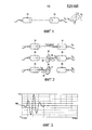
Фиг. 3-5 показывают сигналы, записанные во время трех стадий из Фиг. 2.FIG. 3-5 show signals recorded during the three stages of FIG. 2.
Фиг. 6 показывает стадию наблюдения прошедшей волны во время способа изобретения.FIG. 6 shows the step of observing a transmitted wave during the method of the invention.
Фиг. 7 показывает сигнал, измеренный во время стадии из Фиг. 6.FIG. 7 shows a signal measured during the step of FIG. 6.
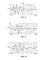
Фиг. 8-10 показывают сигналы, полученные во время стадий из Фиг. 2-6 для проставки, изготовленной из композитного материала.FIG. 8-10 show the signals obtained during the steps of FIG. 2-6 for a spacer made of composite material.
Осуществление изобретенияThe implementation of the invention
Как показано на Фиг. 1, два плоских ультразвуковых датчика, работающих в режиме передачи, устанавливают в положение на одной прямой. Это приведение в положение на одной прямой составляет предварительную стадию E0. Датчики разделены жидкостью, такой как вода. Преобразователь 10 работает в режиме излучения, а датчик 20 в режиме приема. Сигнал, полученный датчиком 20, проходит через максимум после последовательных юстировок осей Oy и Oz, а также углов θ и ϕ.As shown in FIG. 1, two flat ultrasound transducers operating in transmission mode are set to a straight line. This alignment on one straight line constitutes the preliminary stage E0. The sensors are separated by a liquid, such as water. The
На Фиг. 2 представлено измерение толщины материала исследуемой детали, обозначенной 30. Это измерение должно быть с точностью до одного микрометра.In FIG. Figure 2 shows a measurement of the thickness of the material of the test piece, labeled 30. This measurement should be accurate to one micrometer.
Первая стадия Е1 состоит в измерении времени прохождения волны, прошедшей через воду между двумя преобразователями 10 и 20, в отсутствие детали. Вторая стадия состоит в измерении времени прохождения волны, отраженной первой лицевой поверхностью, обозначенной 31, детали 30, преобразователем 10, работающим как приемопередатчик, обращенным к поверхности 31. Третья стадия состоит в измерении времени прохождения волны, отраженной второй поверхностью, обозначенной 32, детали 30, преобразователем 20, работающим, в свою очередь, как приемопередатчик, и обращенным к поверхности 32.The first stage E1 consists in measuring the propagation time of a wave passing through water between two
Время распространения измеряют в каждом случае путем наблюдения начала сигнала, а не дуги сигнала. Это делает возможным для оператора игнорировать любое явление, связанное с возможным фазовым сдвигом сигнала. Конкретно, в присутствии многих отражений появляются фазовые сдвиги. Это также случается, когда после отражения сигнал изменяется по направлению. Форма дуг сигнала модифицируется, и трудно получать точную величину времени распространения. Вот почему предлагается измерять сигнал путем наблюдения исключительно начала сигнала.The propagation time is measured in each case by observing the beginning of the signal, and not the arc of the signal. This makes it possible for the operator to ignore any phenomenon associated with a possible phase shift of the signal. Specifically, in the presence of many reflections, phase shifts appear. This also happens when, after reflection, the signal changes direction. The shape of the signal arcs is modified, and it is difficult to obtain the exact value of the propagation time. That is why it is proposed to measure the signal by observing exclusively the beginning of the signal.
Поскольку скорость распространения волны в воде Vwater является известной, то возможно путем вычитания получать толщину детали из стадий El, E2 и E3, путем использования формулы X2=(tХ1+Х2+Х3-tX3-tХl)×Vwater, где Х1 – расстояние между преобразователем 10 и поверхностью 31, Х2 – толщина детали в точке воздействия пучка, а Х3 – расстояние между преобразователем 20 и поверхностью 32, и где tХ1+Х2+Х3, tХl и tX3 являются временами прохождения, измеренными во время стадий Е1, Е2 и Е3 соответственно.Since the wave propagation velocity V water in the water is known, it is possible to obtain by subtracting the thickness of the part of the steps El, E2 and E3, using the formula X 2 = (t X1 + X2 + x3 t X3- t XL) × V water, where X1 is the distance between
Фиг. 3-5 показывают графики, отображенные во время стадий Е1, Е2 и Е3, соответственно, с водой при 22°C, волной с частотой 5 мегагерц (МГц) (дающей скорость распространения 1486,45 метров в секунду (м/с) в воде), для проставки, имеющей толщину 76,20 миллиметров (мм) и изготовленной из титана TA6V. Время прохождения волны измеряют на основе начала волны, данных соответствующими ссылками 100, 119 и 120.FIG. 3-5 show graphs displayed during stages E1, E2 and E3, respectively, with water at 22 ° C, a wave with a frequency of 5 megahertz (MHz) (giving a propagation speed of 1486.45 meters per second (m / s) in water ), for a spacer having a thickness of 76.20 millimeters (mm) and made of titanium TA6V. The wave propagation time is measured based on the start of the wave given by the
Получены следующие результаты:The following results were obtained:
tХ1+Х2+Х3 92,72 микросекунды (мкс)t X1 + X2 + X3 92.72 microseconds (μs)
tX3 = 2,98/2 = 26,49 мксt X3 = 2,98 / 2 = 26.49 ms
tХl = 26,49/2 = 14,97 мксt Xl = 26.49 / 2 = 14.97 μs
Х2 = (tХ1+Х2+Х3-tХ3-tХ1)Vwater X2 = (t X1 + X2 + X3 -t X3 -t X1 ) V water
Х2 = (92,72 10-6 – 26,49 10-6 – 14,97 10-6) 1486,54X2 = (92.72 10 -6 - 26.49 10 -6 - 14.97 10 -6 ) 1486.54
X2 = 76,20 ммX2 = 76.20 mm
Толщина, измеренная толщиномером, составляет в действительности 76,20 мм, т.е. 3".The thickness measured by the thickness gauge is actually 76.20 mm, i.e. 3 ".
Фиг. 6 показывает стадию Е4, во время которой наблюдается волна, пропущенная деталью 30. Таким образом, преобразователь 10 является работающим в режиме излучения, наряду с тем, что преобразователь 20 является работающим в режиме приема. Падающая волна обозначена 40 на фигуре, волна, распространяющаяся в детали 30, обозначена 41, а прошедшая волна обозначена 42.FIG. 6 shows a step E4 during which a wave transmitted by
Время прохождения волны в детали 30 выражается в виде t'Х2 = t-(tХ1+tХ3). Зная Х2, как определено заранее, скорость распространения волны в материале выражается в виде Vmaterial = Х2/t'Х2.The wave propagation time in the
Фиг. 7 показывает сигнал, наблюдаемый во время стадии Е4 для пространственной проставки толщиной 76,20 мм, изготовленной из титана (TA6V), даже с волной при 5 МГц. Время прохождения волны измеряют на основе начала волны, обозначенного 130.FIG. 7 shows the signal observed during stage E4 for a spatial spacer 76.20 mm thick made of titanium (TA6V), even with a wave at 5 MHz. The wave propagation time is measured based on the start of the wave indicated by 130.
Полученные величины являются следующими:The values obtained are as follows:
t = 53,80 мксt = 53.80 μs
t'Х2 = (53,80 10-6 – 26,49 10-6 – 14,97 10-6)t ' X2 = (53.80 10 -6 - 26.49 10 -6 - 14.97 10 -6 )
t'Х2 = 12,34 мксt ' X2 = 12.34 μs
V=76,20 10-3/l2,34 10-6 V = 76.20 10 -3 / l2.34 10 -6
И, в конце концов, численное значение скорости составляет V = 6175,04 м/с. Эта величина подтверждена с помощью обычного измерения скорости распространения, для того чтобы проверить достоверность результатов способа.And, in the end, the numerical value of the velocity is V = 6175.04 m / s. This value is confirmed using a conventional measurement of the propagation velocity in order to verify the reliability of the results of the method.
Фиг. 8-10 показывают сканограммы, полученные для стадий Е2, Е3 и Е4 для композитной ступенчатой проставки, имеющей толщину 47,09 мм с излучением преобразователя с 1 МГц. Время прохождения волны измерено на основе начал волн, данных соответствующими ссылками 140, 150 и 160.FIG. 8-10 show the scans obtained for stages E2, E3, and E4 for a composite stepped spacer having a thickness of 47.09 mm with transducer radiation from 1 MHz. The wave propagation time is measured based on the wave beginnings given by the corresponding
Полученные величины являются следующими:The values obtained are as follows:
tХ1+Х2+Х3 = 90,22 мксt X1 + X2 + X3 = 90.22 μs
t = 74,90 мксt = 74.90 μs
tX3 = 52,42/2 = 26,41 мксt X3 = 52.42 / 2 = 26.41 μs
tХl = 64,68/2 = 32,34 мксt Xl = 64.68 / 2 = 32.34 μs
Х2 = (tХ1+Х2+Х3-tХ3-tХ1)Vwater X2 = (t X1 + X2 + X3 -t X3 -t X1 ) V water
Х2 = (90,22 10-6 – 26,21 10-6 – 32,34 10-6) 1486,54X2 = (90.22 10 -6 - 26.21 10 -6 - 32.34 10 -6 ) 1486.54
Х2 = 31,67 10-6 1488,76X2 = 31.67 10-6 1488.76
X2 = 47,078 ммX2 = 47.078 mm
t'Х2 = t - (tХ1 + tХ3)t ' X2 = t - (t X1 + t X3 )
t'X2 = (74,90 10-6 – 26,21 10-6 – 32,34 10-6)t ' X2 = (74.90 10 -6 - 26.21 10 -6 - 32.34 10 -6 )
t'Х2 = 16,35 мксt ' X2 = 16.35 μs
Vcomposite = X2/t'Х2 V composite = X2 / t ' X2
Vcomposite = 47,078 10-3/16,35 10-6 V composite = 47.078 10 -3 / 16.35 10 -6
И, в конце концов, численное значение скорости составляет Vcomposite = 2879,4 м/с.And, in the end, the numerical value of the velocity is V composite = 2879.4 m / s.
Затем внимание уделено затуханию продольной волны в материале.Then attention is paid to the attenuation of the longitudinal wave in the material.
Выражение для амплитуды волны, прошедшей от излучателя к приемнику, записывается как следующее: Y1 = Amaxe-α1(Х1+Х2+Х3), где Амах представляет максимальную амплитуду на поверхности преобразователя, и α1 представляет собой затухание волны в воде.The expression for the amplitude of the wave transmitted from the emitter to the receiver is written as follows: Y 1 = A max e - α 1 (X1 + X2 + X3 ), where A max represents the maximum amplitude on the surface of the transducer, and α 1 represents the attenuation of the wave in water.
Выражение для амплитуды волны, прошедшей от излучателя к приемнику после прохождения через материал, записано как следующее: Y2 = Amaxe-α1(Х1+Х3)e-α2Х2t12t21, где α2 представляет собой затухание волны в материале, t12 является коэффициентом амплитудного пропускания от воды к материалу, а t21 является коэффициентом амплитудного пропускания от материала к воде.The expression for the amplitude of the wave transmitted from the transmitter to the receiver after passing through the material is recorded as the following: Y 2 = A max e - α 1 (X1 + X3) e - α 2X2 t 12 t 21, wherein α 2 is the wave attenuation in material, t 12 is the coefficient of amplitude transmittance from water to material, and t 21 is the coefficient of amplitude transmittance from material to water.
Выражение для продукта t12t21 является функцией акустического импеданса материала Z2 = ρ2V2 и акустического импеданса воды Z1 = ρ1V1. В выражении акустического импеданса ρ представляет плотность и V представляет скорость распространения продольной волны с обсуждаемой частотой.The expression for the product t 12 t 21 is a function of the acoustic impedance of the material Z 2 = ρ 2 V 2 and the acoustic impedance of water Z 1 = ρ 1 V 1 . In terms of acoustic impedance, ρ represents the density and V represents the propagation velocity of the longitudinal wave with the frequency discussed.
![]()

![]()
Амплитудное отношение Y1/Y2 записывается как следующее:The amplitude ratio Y 1 / Y 2 is written as follows:

Из которой возможно вывести выражение для затухания в материале:From which it is possible to derive an expression for attenuation in a material:

Первое осуществление относится к проставке из композитного материала, имеющего толщину 47,09 мм, использующему волну с 2,25 МГц.The first embodiment relates to a spacer made of a composite material having a thickness of 47.09 mm using a wavelength of 2.25 MHz.
Численные значения для этого осуществления являются следующими:The numerical values for this implementation are as follows:
ρ2 = 1525, 71 килограмм на кубический метр (кг/м3)ρ 2 = 1525, 71 kilograms per cubic meter (kg / m 3 )
V2 = 2946,75 м/сV 2 = 2946.75 m / s
Z2 = 4,39316 мегаом на переменном токе (MΩac)Z 2 = 4.39316 megaohms on alternating current (MΩac)
ρwater = 997.77 кг/м3 ρ water = 997.77 kg / m 3
Vwater = I486,54 м/cV water = I486.54 m / s
Zwater = 1,48322 MΩacZ water = 1.48322 MΩac
t12 t21 = 0,75478t 12 t 21 = 0.75478
Х2 = 47,078 мм (точное ультразвуковое измерение)X 2 = 47.078 mm (accurate ultrasonic measurement)
Y1 = 643,2 милливольт (мВ)Y 1 = 643.2 millivolts (mV)
Y2 = 15,885 мВY 2 = 15.885 mV
αwater2,25Мгц = 0,972 непера на метр (Нп/м)α water2.25MHz = 0.972 neper per meter (Np / m)
α2 = 73,61 Нп/м.α 2 = 73.61 H / m.
Второе осуществление относится к проставке из композитного материала, имеющей толщину 47,09 мм, использующее волну с 1 МГц.The second embodiment relates to a spacer made of a composite material having a thickness of 47.09 mm using a wavelength of 1 MHz.
ρ2 = 1525,71 кг/м3 ρ 2 = 1525.71 kg / m 3
V2 = 2879,39 м/сV 2 = 2879.39 m / sec
Z2 = 4,39311 MΩacZ 2 = 4.39311 MΩac
ρwater = 997,77 кг/м3 ρ water = 997.77 kg / m 3
Vwater = I486,54 м/cV water = I486.54 m / s
Zwater = 1,48322 MΩacZ water = 1,48322 MΩac
t12t21 = 0,75479t 12 t 21 = 0.75479
Х2 = 47,078 мм (точное ультразвуковое измерение)X 2 = 47.078 mm (accurate ultrasonic measurement)
Y1 = 370,25 мВY 1 = 370.25 mV
Y2 = 16,395 мВY 2 = 16.395 mV
αwater1Мгц = 0,682 Нп/мα water1MHz = 0.682 Np / m
α2 = 60,92 Нп/м.α 2 = 60.92 Np / m.
Изобретение не ограничивается описанными реализациями, а распространяется на любой вариант в пределах объема формулы изобретения.The invention is not limited to the described implementations, but extends to any option within the scope of the claims.
Claims (5)
Applications Claiming Priority (3)
| Application Number | Priority Date | Filing Date | Title |
|---|---|---|---|
| FR1262155A FR2999714B1 (en) | 2012-12-17 | 2012-12-17 | PROCESS FOR CHARACTERIZING A PIECE OF COMPOSITE MATERIAL |
| FR1262155 | 2012-12-17 | ||
| PCT/FR2013/052985 WO2014096617A1 (en) | 2012-12-17 | 2013-12-06 | Method for characterising a part made of a composite material |
Publications (2)
| Publication Number | Publication Date |
|---|---|
| RU2015129071A RU2015129071A (en) | 2017-01-25 |
| RU2642503C2 true RU2642503C2 (en) | 2018-01-25 |
Family
ID=48083238
Family Applications (1)
| Application Number | Title | Priority Date | Filing Date |
|---|---|---|---|
| RU2015129071A RU2642503C2 (en) | 2012-12-17 | 2013-12-06 | Method of characterizng part manufactured from composite material |
Country Status (9)
| Country | Link |
|---|---|
| US (1) | US10024822B2 (en) |
| EP (1) | EP2932255B1 (en) |
| JP (1) | JP6542125B2 (en) |
| CN (1) | CN104870994B (en) |
| BR (1) | BR112015014246B1 (en) |
| CA (1) | CA2894588C (en) |
| FR (1) | FR2999714B1 (en) |
| RU (1) | RU2642503C2 (en) |
| WO (1) | WO2014096617A1 (en) |
Families Citing this family (2)
| Publication number | Priority date | Publication date | Assignee | Title |
|---|---|---|---|---|
| CN108896664B (en) * | 2018-06-06 | 2020-06-09 | 浙江大学 | Integrated detection method for sound velocity and attenuation coefficient in polymer |
| US11359918B2 (en) * | 2020-07-24 | 2022-06-14 | Olympus Scientific Solutions Americas Corp. | Ultrasonic testing with single shot processing |
Citations (5)
| Publication number | Priority date | Publication date | Assignee | Title |
|---|---|---|---|---|
| US4515545A (en) * | 1981-07-09 | 1985-05-07 | Applied Polymer Technology, Inc. | Control system for processing composite material |
| DE4233958A1 (en) * | 1992-10-08 | 1994-04-14 | Geotron Elektronik Rolf Kromph | Ultrasonic testing of composite mineral building materials - using longitudinal wave with axial and radial component, and analysing mixture of component frequencies by rapid FFT |
| US5408882A (en) * | 1991-06-24 | 1995-04-25 | General Electric Company | Ultrasonic device and method for non-destructive evaluation of polymer composites |
| US5824908A (en) * | 1994-12-12 | 1998-10-20 | Queen's University At Kingston | Non-contact characterization and inspection of materials using wideband air coupled ultrasound |
| RU2280251C1 (en) * | 2004-11-23 | 2006-07-20 | Федеральное государственное унитарное предприятие "Научно-исследовательский институт Научно-производственное объединение "Луч" | Method for controlling composition of two-phased composites |
Family Cites Families (38)
| Publication number | Priority date | Publication date | Assignee | Title |
|---|---|---|---|---|
| US3930404A (en) * | 1973-06-21 | 1976-01-06 | Exxon Nuclear Company Inc. | Inside diameter, outside diameter and wall tube gage |
| BE840456A (en) * | 1975-04-22 | 1976-10-07 | DEVICE FOR PRECISE MEASUREMENT OF THE DIMENSIONS OF AN OBJECT BY ULTRA-SOUND | |
| DE2902017A1 (en) * | 1979-01-19 | 1980-07-24 | Krautkraemer Gmbh | METHOD FOR COMPENSATING TEMPERATURE INFLUENCES ON THE SOUND SPEED IN A COUPLING LIQUID FOR THE ULTRASONIC TEST |
| US4404853A (en) * | 1981-03-12 | 1983-09-20 | Livingston Waylon A | Method and apparatus for ultrasonic testing of tubular goods |
| SE425996B (en) * | 1981-12-22 | 1982-11-29 | Salomonsson Goeran | SET AND DEVICE FOR GENERATING SHORT ULTRASONIC COUPLES |
| JPS60163643A (en) * | 1984-02-07 | 1985-08-26 | テルモ株式会社 | Ultrasonic measuring method and apparatus |
| WO1989006796A1 (en) | 1988-01-22 | 1989-07-27 | Kline Ronald A | System for nondestructively determining composite material parameters |
| US5181421A (en) * | 1988-01-22 | 1993-01-26 | Board Of Regents Of The University Of Oklahoma | Automatic monitoring of composite prepregs |
| US5009103A (en) * | 1988-02-01 | 1991-04-23 | Tokyo Keiki Co., Ltd. | Ultrasonic thickness measuring method and apparatus |
| FR2646239B1 (en) * | 1989-04-24 | 1991-08-16 | Dassault Avions | ACOUSTIC METHOD AND DEVICE FOR LOCATING DEFECTS IN THE MATERIAL CONSTITUTING A PART AND ACOUSTIC TRANSMITTER FOR USE IN THIS DEVICE |
| FR2654508B1 (en) * | 1989-11-14 | 1992-02-21 | Aerospatiale Ste Nat Indle | DEVICE AND PROBE FOR MEASURING THE VARIATION IN DISTANCE SEPARATING BOTH FACES OF A MATERIAL LAYER USING ULTRASOUND. |
| US5072388A (en) * | 1990-01-31 | 1991-12-10 | Union Oil Company Of California | Lined casing inspection method |
| US5170367A (en) * | 1990-04-25 | 1992-12-08 | The Expert System Technologies, Inc. | Nondestructive determination of phase fractions of composite materials |
| US5201225A (en) * | 1990-09-24 | 1993-04-13 | Toyo Kanetsu K.K. | Instrument for measuring thickness of coated plate and method thereof |
| US5156636A (en) * | 1990-11-26 | 1992-10-20 | Combustion Engineering, Inc. | Ultrasonic method and apparatus for measuring outside diameter and wall thickness of a tube and having temperature compensation |
| JPH05172793A (en) | 1991-12-18 | 1993-07-09 | Hitachi Ltd | Acoustic characteristic value measuring device |
| JP3052532B2 (en) | 1992-01-21 | 2000-06-12 | 株式会社島津製作所 | Ultrasonic transmission inspection equipment |
| JPH0749944B2 (en) | 1992-07-10 | 1995-05-31 | 工業技術院長 | Simultaneous measurement of material thickness and sound velocity |
| US5448915A (en) * | 1993-09-02 | 1995-09-12 | Hughes Aircraft Company | Method for improving the accuracy of ultrasonic thickness measurements by calibrating for surface finish |
| JP3468573B2 (en) | 1994-03-22 | 2003-11-17 | 積水化学工業株式会社 | Defect inspection device for resin mortar composite pipe |
| US5596508A (en) * | 1994-12-07 | 1997-01-21 | Krautkramer-Branson, Inc. | High resolution measurement of a thickness using ultrasound |
| US5661241A (en) * | 1995-09-11 | 1997-08-26 | The Babcock & Wilcox Company | Ultrasonic technique for measuring the thickness of cladding on the inside surface of vessels from the outside diameter surface |
| FR2806801B1 (en) * | 2000-03-23 | 2002-05-03 | Snecma | RESILIENCE EVALUATION METHOD OF A WELDED ASSEMBLY AND CORRESPONDING ANALYSIS APPARATUS MEASURING SURFACE ULTRASONIC WAVE SPEEDS |
| US6534964B1 (en) * | 2000-09-22 | 2003-03-18 | International Business Machines Corporation | Apparatus and method for determining stiffness properties of an anisotropic electronic substrate using scanning acoustic microscopy |
| US6634233B2 (en) * | 2001-01-23 | 2003-10-21 | Wright State University | Method for determining the wall thickness and the speed of sound in a tube from reflected and transmitted ultrasound pulses |
| US6883376B2 (en) * | 2001-01-23 | 2005-04-26 | Wright State University | Method for determining the wall thickness and the speed of sound in a tube from reflected and transmitted ultrasound pulses |
| EP1491886B1 (en) * | 2003-06-23 | 2006-10-18 | Zumbach Electronic Ag | Apparatus and method for calibration and ultrasound inspection of cylindrical bodies |
| FR2866119B1 (en) * | 2004-02-05 | 2006-09-15 | Snecma Moteurs | METHOD FOR MEASURING THE ADHESION OF A COATING ON A SUBSTRATE |
| US7426865B2 (en) | 2005-11-22 | 2008-09-23 | General Electric Company | Method for ultrasonic elastic modulus calculation and imaging |
| US7823451B2 (en) * | 2008-05-06 | 2010-11-02 | The Boeing Company | Pulse echo/through transmission ultrasonic testing |
| US8161818B2 (en) * | 2008-10-29 | 2012-04-24 | Airbus Operations Gmbh | Device for detecting a flaw in a component |
| FR2959817B1 (en) * | 2010-05-10 | 2012-06-22 | Snecma | ULTRASONIC CONTROL METHOD OF A COMPOSITE PIECE. |
| US8857269B2 (en) * | 2010-08-05 | 2014-10-14 | Hospira, Inc. | Method of varying the flow rate of fluid from a medical pump and hybrid sensor system performing the same |
| FR2972802B1 (en) * | 2011-03-16 | 2013-09-20 | Snecma | NON-DESTRUCTIVE CONTROL SYSTEM, BY ULTRASOUND IN IMMERSION, OF PARTS |
| JP5755993B2 (en) * | 2011-10-21 | 2015-07-29 | 理想科学工業株式会社 | Ultrasonic sensor |
| FR2984505B1 (en) * | 2011-12-19 | 2014-01-31 | Snecma | METHOD OF MEASURING ULTRASONIC ELASTIC PROPERTIES. |
| FR2993361B1 (en) * | 2012-07-10 | 2014-08-01 | Snecma | METHOD FOR CHARACTERIZING AN OBJECT COMPRISING AT LEAST LOCALLY A SYMMETRY PLAN |
| CN102788738A (en) * | 2012-09-03 | 2012-11-21 | 北京理工大学 | Ultrasonic array detection method for multi-phase liquid density and concentration |
-
2012
- 2012-12-17 FR FR1262155A patent/FR2999714B1/en active Active
-
2013
- 2013-12-06 JP JP2015547114A patent/JP6542125B2/en active Active
- 2013-12-06 CN CN201380066149.3A patent/CN104870994B/en active Active
- 2013-12-06 BR BR112015014246-0A patent/BR112015014246B1/en active IP Right Grant
- 2013-12-06 US US14/652,593 patent/US10024822B2/en active Active
- 2013-12-06 WO PCT/FR2013/052985 patent/WO2014096617A1/en not_active Ceased
- 2013-12-06 EP EP13821862.3A patent/EP2932255B1/en active Active
- 2013-12-06 CA CA2894588A patent/CA2894588C/en active Active
- 2013-12-06 RU RU2015129071A patent/RU2642503C2/en active
Patent Citations (5)
| Publication number | Priority date | Publication date | Assignee | Title |
|---|---|---|---|---|
| US4515545A (en) * | 1981-07-09 | 1985-05-07 | Applied Polymer Technology, Inc. | Control system for processing composite material |
| US5408882A (en) * | 1991-06-24 | 1995-04-25 | General Electric Company | Ultrasonic device and method for non-destructive evaluation of polymer composites |
| DE4233958A1 (en) * | 1992-10-08 | 1994-04-14 | Geotron Elektronik Rolf Kromph | Ultrasonic testing of composite mineral building materials - using longitudinal wave with axial and radial component, and analysing mixture of component frequencies by rapid FFT |
| US5824908A (en) * | 1994-12-12 | 1998-10-20 | Queen's University At Kingston | Non-contact characterization and inspection of materials using wideband air coupled ultrasound |
| RU2280251C1 (en) * | 2004-11-23 | 2006-07-20 | Федеральное государственное унитарное предприятие "Научно-исследовательский институт Научно-производственное объединение "Луч" | Method for controlling composition of two-phased composites |
Also Published As
| Publication number | Publication date |
|---|---|
| US20150330949A1 (en) | 2015-11-19 |
| BR112015014246A2 (en) | 2017-07-11 |
| WO2014096617A1 (en) | 2014-06-26 |
| BR112015014246B1 (en) | 2021-02-23 |
| JP6542125B2 (en) | 2019-07-10 |
| US10024822B2 (en) | 2018-07-17 |
| CN104870994A (en) | 2015-08-26 |
| CA2894588C (en) | 2020-11-10 |
| CA2894588A1 (en) | 2014-06-26 |
| EP2932255B1 (en) | 2019-06-26 |
| JP2016503881A (en) | 2016-02-08 |
| EP2932255A1 (en) | 2015-10-21 |
| FR2999714B1 (en) | 2016-01-15 |
| FR2999714A1 (en) | 2014-06-20 |
| RU2015129071A (en) | 2017-01-25 |
| CN104870994B (en) | 2019-02-12 |
Similar Documents
| Publication | Publication Date | Title |
|---|---|---|
| US10481131B2 (en) | Ultrasonic test system, ultrasonic test method and method of manufacturing aircraft part | |
| Yan et al. | Ultrasonic imaging of full matrix capture acquired data for carbon fibre-reinforced polymer | |
| JP6082023B2 (en) | Method for measuring elastic properties using ultrasound | |
| CN102636576A (en) | Measuring method for delay and leading edge of sound-transmission-wedge surface wave probe | |
| JP5311766B2 (en) | Interface inspection apparatus and interface inspection method | |
| CN106596725A (en) | Method for ultrasonic distinguishing of R-region defect of composite material structure | |
| JP6671565B2 (en) | Ultrasonic flaw detector | |
| CN104833323A (en) | Method for measuring the width of laser lapping welding seam by using reflected echo of S0 mode lamb wave | |
| Arun et al. | An EMAT-based shear horizontal (SH) wave technique for adhesive bond inspection | |
| RU2642503C2 (en) | Method of characterizng part manufactured from composite material | |
| CA2725297A1 (en) | Improved non-destructive ultrasonic testing with coupling check | |
| JP5567472B2 (en) | Ultrasonic inspection method and ultrasonic inspection apparatus | |
| Athanassiadis et al. | Broadband leaky Lamb waves excited by optical breakdown in water | |
| KR102727365B1 (en) | Ultrasonic sensor for residual stress measurement | |
| RU2231054C1 (en) | Method of determination of degree of polymerization of composite materials | |
| JP3493941B2 (en) | Ultrasonic probe | |
| Takatsubo et al. | Generation laser scanning method for visualizing ultrasonic waves propagating on 3-D objects | |
| JP2011203199A (en) | Precise flaw detection method by utilization of sound absorbing material | |
| Mihara et al. | Ultrasonic inspection of rocket fuel model using laminated transducer and multi-channel step pulser | |
| Jakevičius et al. | Measurement of thickness of layer and sound velocity in multi-layered structure by the use of angular ultrasonic transducers | |
| Gudimetla et al. | Simulation of delaminations in composite laminates | |
| Takatsubo et al. | Visualization of ultrasonic waves scattered from rear defects by using a laser‐based imaging technique | |
| Chu et al. | Ultrasonic edge waves for damage detection in composite plate stiffeners | |
| Kimura et al. | Discussion on transmission and reception of shear vertical wave propagating along surface of test object | |
| JP6440371B2 (en) | Ultrasonic measuring apparatus and method |
Legal Events
| Date | Code | Title | Description |
|---|---|---|---|
| PD4A | Correction of name of patent owner |