RU2633361C2 - Execution method of universal led bulb, led bulb, having a stopping ring structure, and a led lamp - Google Patents
Execution method of universal led bulb, led bulb, having a stopping ring structure, and a led lamp Download PDFInfo
- Publication number
- RU2633361C2 RU2633361C2 RU2015105969A RU2015105969A RU2633361C2 RU 2633361 C2 RU2633361 C2 RU 2633361C2 RU 2015105969 A RU2015105969 A RU 2015105969A RU 2015105969 A RU2015105969 A RU 2015105969A RU 2633361 C2 RU2633361 C2 RU 2633361C2
- Authority
- RU
- Russia
- Prior art keywords
- radiator
- lamp
- led
- cap
- bulb
- Prior art date
Links
Images


Classifications
-
- F—MECHANICAL ENGINEERING; LIGHTING; HEATING; WEAPONS; BLASTING
- F21—LIGHTING
- F21V—FUNCTIONAL FEATURES OR DETAILS OF LIGHTING DEVICES OR SYSTEMS THEREOF; STRUCTURAL COMBINATIONS OF LIGHTING DEVICES WITH OTHER ARTICLES, NOT OTHERWISE PROVIDED FOR
- F21V17/00—Fastening of component parts of lighting devices, e.g. shades, globes, refractors, reflectors, filters, screens, grids or protective cages
- F21V17/06—Fastening of component parts of lighting devices, e.g. shades, globes, refractors, reflectors, filters, screens, grids or protective cages the fastening being onto or by the lampholder
-
- F—MECHANICAL ENGINEERING; LIGHTING; HEATING; WEAPONS; BLASTING
- F21—LIGHTING
- F21K—NON-ELECTRIC LIGHT SOURCES USING LUMINESCENCE; LIGHT SOURCES USING ELECTROCHEMILUMINESCENCE; LIGHT SOURCES USING CHARGES OF COMBUSTIBLE MATERIAL; LIGHT SOURCES USING SEMICONDUCTOR DEVICES AS LIGHT-GENERATING ELEMENTS; LIGHT SOURCES NOT OTHERWISE PROVIDED FOR
- F21K9/00—Light sources using semiconductor devices as light-generating elements, e.g. using light-emitting diodes [LED] or lasers
- F21K9/20—Light sources comprising attachment means
- F21K9/23—Retrofit light sources for lighting devices with a single fitting for each light source, e.g. for substitution of incandescent lamps with bayonet or threaded fittings
- F21K9/232—Retrofit light sources for lighting devices with a single fitting for each light source, e.g. for substitution of incandescent lamps with bayonet or threaded fittings specially adapted for generating an essentially omnidirectional light distribution, e.g. with a glass bulb
-
- F—MECHANICAL ENGINEERING; LIGHTING; HEATING; WEAPONS; BLASTING
- F21—LIGHTING
- F21S—NON-PORTABLE LIGHTING DEVICES; SYSTEMS THEREOF; VEHICLE LIGHTING DEVICES SPECIALLY ADAPTED FOR VEHICLE EXTERIORS
- F21S8/00—Lighting devices intended for fixed installation
-
- F—MECHANICAL ENGINEERING; LIGHTING; HEATING; WEAPONS; BLASTING
- F21—LIGHTING
- F21V—FUNCTIONAL FEATURES OR DETAILS OF LIGHTING DEVICES OR SYSTEMS THEREOF; STRUCTURAL COMBINATIONS OF LIGHTING DEVICES WITH OTHER ARTICLES, NOT OTHERWISE PROVIDED FOR
- F21V15/00—Protecting lighting devices from damage
- F21V15/01—Housings, e.g. material or assembling of housing parts
-
- F—MECHANICAL ENGINEERING; LIGHTING; HEATING; WEAPONS; BLASTING
- F21—LIGHTING
- F21V—FUNCTIONAL FEATURES OR DETAILS OF LIGHTING DEVICES OR SYSTEMS THEREOF; STRUCTURAL COMBINATIONS OF LIGHTING DEVICES WITH OTHER ARTICLES, NOT OTHERWISE PROVIDED FOR
- F21V21/00—Supporting, suspending, or attaching arrangements for lighting devices; Hand grips
- F21V21/02—Wall, ceiling, or floor bases; Fixing pendants or arms to the bases
- F21V21/03—Ceiling bases, e.g. ceiling roses
-
- F—MECHANICAL ENGINEERING; LIGHTING; HEATING; WEAPONS; BLASTING
- F21—LIGHTING
- F21V—FUNCTIONAL FEATURES OR DETAILS OF LIGHTING DEVICES OR SYSTEMS THEREOF; STRUCTURAL COMBINATIONS OF LIGHTING DEVICES WITH OTHER ARTICLES, NOT OTHERWISE PROVIDED FOR
- F21V21/00—Supporting, suspending, or attaching arrangements for lighting devices; Hand grips
- F21V21/14—Adjustable mountings
- F21V21/30—Pivoted housings or frames
-
- F—MECHANICAL ENGINEERING; LIGHTING; HEATING; WEAPONS; BLASTING
- F21—LIGHTING
- F21V—FUNCTIONAL FEATURES OR DETAILS OF LIGHTING DEVICES OR SYSTEMS THEREOF; STRUCTURAL COMBINATIONS OF LIGHTING DEVICES WITH OTHER ARTICLES, NOT OTHERWISE PROVIDED FOR
- F21V23/00—Arrangement of electric circuit elements in or on lighting devices
- F21V23/06—Arrangement of electric circuit elements in or on lighting devices the elements being coupling devices, e.g. connectors
-
- F—MECHANICAL ENGINEERING; LIGHTING; HEATING; WEAPONS; BLASTING
- F21—LIGHTING
- F21V—FUNCTIONAL FEATURES OR DETAILS OF LIGHTING DEVICES OR SYSTEMS THEREOF; STRUCTURAL COMBINATIONS OF LIGHTING DEVICES WITH OTHER ARTICLES, NOT OTHERWISE PROVIDED FOR
- F21V29/00—Protecting lighting devices from thermal damage; Cooling or heating arrangements specially adapted for lighting devices or systems
- F21V29/50—Cooling arrangements
- F21V29/70—Cooling arrangements characterised by passive heat-dissipating elements, e.g. heat-sinks
- F21V29/74—Cooling arrangements characterised by passive heat-dissipating elements, e.g. heat-sinks with fins or blades
-
- F—MECHANICAL ENGINEERING; LIGHTING; HEATING; WEAPONS; BLASTING
- F21—LIGHTING
- F21V—FUNCTIONAL FEATURES OR DETAILS OF LIGHTING DEVICES OR SYSTEMS THEREOF; STRUCTURAL COMBINATIONS OF LIGHTING DEVICES WITH OTHER ARTICLES, NOT OTHERWISE PROVIDED FOR
- F21V31/00—Gas-tight or water-tight arrangements
-
- F—MECHANICAL ENGINEERING; LIGHTING; HEATING; WEAPONS; BLASTING
- F21—LIGHTING
- F21S—NON-PORTABLE LIGHTING DEVICES; SYSTEMS THEREOF; VEHICLE LIGHTING DEVICES SPECIALLY ADAPTED FOR VEHICLE EXTERIORS
- F21S8/00—Lighting devices intended for fixed installation
- F21S8/02—Lighting devices intended for fixed installation of recess-mounted type, e.g. downlighters
- F21S8/026—Lighting devices intended for fixed installation of recess-mounted type, e.g. downlighters intended to be recessed in a ceiling or like overhead structure, e.g. suspended ceiling
-
- F—MECHANICAL ENGINEERING; LIGHTING; HEATING; WEAPONS; BLASTING
- F21—LIGHTING
- F21W—INDEXING SCHEME ASSOCIATED WITH SUBCLASSES F21K, F21L, F21S and F21V, RELATING TO USES OR APPLICATIONS OF LIGHTING DEVICES OR SYSTEMS
- F21W2131/00—Use or application of lighting devices or systems not provided for in codes F21W2102/00-F21W2121/00
- F21W2131/10—Outdoor lighting
- F21W2131/103—Outdoor lighting of streets or roads
-
- F—MECHANICAL ENGINEERING; LIGHTING; HEATING; WEAPONS; BLASTING
- F21—LIGHTING
- F21Y—INDEXING SCHEME ASSOCIATED WITH SUBCLASSES F21K, F21L, F21S and F21V, RELATING TO THE FORM OR THE KIND OF THE LIGHT SOURCES OR OF THE COLOUR OF THE LIGHT EMITTED
- F21Y2113/00—Combination of light sources
-
- F—MECHANICAL ENGINEERING; LIGHTING; HEATING; WEAPONS; BLASTING
- F21—LIGHTING
- F21Y—INDEXING SCHEME ASSOCIATED WITH SUBCLASSES F21K, F21L, F21S and F21V, RELATING TO THE FORM OR THE KIND OF THE LIGHT SOURCES OR OF THE COLOUR OF THE LIGHT EMITTED
- F21Y2115/00—Light-generating elements of semiconductor light sources
- F21Y2115/10—Light-emitting diodes [LED]
Landscapes
- Engineering & Computer Science (AREA)
- General Engineering & Computer Science (AREA)
- Physics & Mathematics (AREA)
- Microelectronics & Electronic Packaging (AREA)
- Optics & Photonics (AREA)
- Arrangement Of Elements, Cooling, Sealing, Or The Like Of Lighting Devices (AREA)
- Non-Portable Lighting Devices Or Systems Thereof (AREA)
- Led Device Packages (AREA)
- Fastening Of Light Sources Or Lamp Holders (AREA)
Abstract
Description
Область техники, к которой относится изобретениеFIELD OF THE INVENTION
Настоящее изобретение относится к способу выполнения универсальной светодиодной лампочки, светодиодной лампочке, имеющей конструкцию стопорного кольца, и светодиодной лампе, которые затрагивают область технологии светодиодного освещения.The present invention relates to a method for making a universal LED light bulb, an LED light bulb having a retaining ring structure, and an LED lamp that affect the field of LED lighting technology.
Уровень техники изобретенияBACKGROUND OF THE INVENTION
В качестве нового поколения технологии освещения светодиодное полупроводниковое освещение имеет пять энергосберегающих преимуществ, не сравнимых с существующими другими технологиями освещения, такие как высокая эффективность фотоэлектрического преобразования, простое управление направлением источника света, простое управление временем и путем освещения, высокое качество цветопередачи источника света и высокий коэффициент мощности при целесообразной конструкции, таким образом, будучи хорошо принимаемым инвесторами по всему миру и решительно поддерживаемым правительствами всех стран. Световая эффективность самых современных светодиодных ламп может превышать 70 лм/Вт, таким образом, имея более хорошие энергосберегающие преимущества, чем традиционные энергосберегающие лампы. Световая эффективность зеленых светодиодов может теоретически достигать 683 лм/Вт; теоретическая эффективность белого светодиода также достигает 182,45 лм/Вт, так что предел улучшения эффективности светодиодного освещения является широким.As a new generation of lighting technology, LED semiconductor lighting has five energy-saving advantages that are not comparable with other other lighting technologies, such as high photoelectric conversion efficiency, simple control of the direction of the light source, simple time and light control, high color rendering of the light source and high coefficient suitable design, thus being well received by investors around the world and strongly supported by the governments of all countries. The luminous efficiency of the most modern LED lamps can exceed 70 lm / W, thus having better energy-saving advantages than traditional energy-saving lamps. The luminous efficiency of green LEDs can theoretically reach 683 lm / W; the theoretical efficiency of the white LED also reaches 182.45 lm / W, so the limit of improving the efficiency of LED lighting is wide.
В современной конструкции высокомощных светодиодных осветительных изделий, в особенности высокомощных светодиодных ламп, из-за рассеивания тепла при сборке высокомощной светодиодной лампы светодиодный световой модуль, источник мощности возбуждения и лампа выполняются за одно целое, а именно, такие компоненты, как светодиодный световой модуль, источник мощности возбуждения и лампа должны производиться совместно, таким образом, создавая ситуацию «лампы, имеющей светодиод при отсутствии лампочки». Это приносит ряд неизбежных проблем для светодиодных осветительных изделий, таких как высокая стоимость изготовления, неудобство использования, трудность обслуживания и т.п.Во-первых, отечественное и даже мировое равномерное стандартизированное производство не может быть достигнуто при изготовлении, приводя к многочисленным спецификациям изделий, небольшим партиям и высоким ценам; во-вторых, изделия производителей являются разнообразными, не универсальными, не говоря уже о взаимозаменяемости; в-третьих, светодиодный световой модуль, источник мощности возбуждения, лампу и т.п.необходимо отделять за одно целое для обслуживания в случае выхода из строя изделия, таким образом, обслуживание является очень неудобным, и такие недостатки, как расширенный выход из строя, отсроченное обслуживание и высокая стоимость обслуживания и т.п.весьма склонны к образованию. Эти недостатки значительно ограничивают популяризацию и использование светодиодного освещения и являются неотъемлемыми проблемами при популяризации светодиодных осветительных изделий.In the modern design of high-power LED lighting products, especially high-power LED lamps, due to heat dissipation during the assembly of a high-power LED lamp, the LED light module, the excitation power source and the lamp are made in one piece, namely, components such as LED light module, source the excitation power and the lamp must be produced together, thus creating the situation of a “lamp having an LED in the absence of a lamp”. This brings a number of inevitable problems for LED lighting products, such as the high cost of manufacture, inconvenience of use, difficulty of maintenance, etc. Firstly, domestic and even worldwide uniform standardized production cannot be achieved in the manufacture, leading to numerous product specifications. small parties and high prices; secondly, manufacturers' products are diverse, not universal, not to mention interchangeability; thirdly, the LED light module, the excitation power source, the lamp, etc., need to be separated for service in case of failure of the product, thus, maintenance is very inconvenient, and such disadvantages as extended failure, deferred maintenance and the high cost of maintenance, etc. are all prone to education. These disadvantages significantly limit the popularization and use of LED lighting and are inherent problems in the promotion of LED lighting products.
Сущность изобретенияSUMMARY OF THE INVENTION
Задачей настоящего изобретения является обеспечение способа выполнения универсальной светодиодной лампочки, светодиодной лампочки, имеющей конструкцию стопорного кольца, и светодиодной лампы. Она имеет простую и устойчивую конструкцию, удобно устанавливается, способна обеспечиваться радиатором с возможностью независимой работы и также может быть установлена на радиаторе лампы, таким образом, используясь гибко. С помощью принятия настоящего изобретения светодиодная лампочка независимо производится и используется с такими изделиями, как лампа и управление освещением и т.п.на производстве, тем самым значительно уменьшая процедуры производства светодиодных осветительных изделий, улучшая массовое производство и облегчая промышленное производство светодиодных энергосберегающих осветительных изделий.An object of the present invention is to provide a method for making a universal LED bulb, an LED bulb having a retaining ring structure, and an LED lamp. It has a simple and stable design, it is conveniently installed, it can be provided with a radiator with the possibility of independent operation and can also be installed on the radiator of the lamp, thus being used flexibly. By adopting the present invention, an LED light bulb is independently produced and used with products such as a lamp and lighting control and the like in production, thereby significantly reducing the production procedures of LED lighting products, improving mass production and facilitating the industrial production of LED energy-saving lighting products.
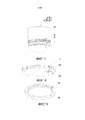
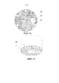
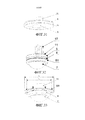
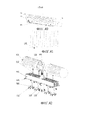
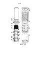
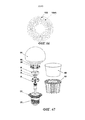
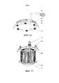
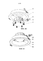
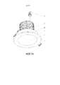
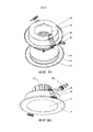
Технические решения настоящего изобретения заключаются в следующем: способ выполнения универсальной светодиодной лампочки, содержащий этапы, на которых: поддерживают элемент каркаса оптического источника светодиодной лампочки в стопорном кольце линзы, используя стопорное кольцо линзы в качестве опорного главного корпуса лампочки, используют внутреннее стопорное кольцо, обеспеченное на внутренней стороне оптической линзы распределения света в элементе каркаса оптического источника светодиодной лампочки, в качестве вспомогательной опорной конструкции лампочки и используют внутреннее стопорное кольцо в качестве базы установки модуля оптического источника и теплопроводящего кронштейна или базы установки радиатора светодиодной лампочки, элемент каркаса оптического источника светодиодной лампочки составляют из теплопроводящего кронштейна, модуля оптического источника, внутреннего стопорного кольца и оптической линзы распределения света, причем верхний конец внутреннего стопорного кольца склеен с теплопроводящим кронштейном, нижний конец внутреннего стопорного кольца склеен с оптической линзой распределения света так, что уплотненное водонепроницаемое пространство для заключения модуля оптического механизма образовано внутренним стопорным кольцом, теплопроводящим кронштейном и оптической линзой распределения света; снаружи модуля оптического источника обеспечивают внутреннюю крышку, и электрический соединитель прикрепляют к теплопроводящему кронштейну; установочный фланец прикрепляют к стопорному кольцу линзы для установки лампочки; модуль оптического источника составляют из пластины матрицы оптического источника, набора светодиодных чипов и соответствующей проводки путем пайки и герметизации или дополнительно объединяют с чипом для возбуждения источника питания.The technical solutions of the present invention are as follows: a method for making a universal LED light bulb, comprising the steps of: supporting a frame element of an optical source of an LED light bulb in a lens retaining ring, using the lens retaining ring as a support main bulb body, using the inner retaining ring provided on the inner side of the optical lens of the light distribution in the frame element of the optical source of the LED bulb, as an auxiliary of the supporting structure of the light bulb and use the internal retaining ring as the base for installing the optical source module and the heat-conducting bracket or the base for installing the LED heatsink, the frame element of the optical light source of the LED light is composed of the heat-conducting bracket, the optical source module, the internal retaining ring and the optical light distribution lens, moreover, the upper end of the inner retainer ring is glued with a heat-conducting bracket, the lower end of the inner retainer the ring is glued to the optical light distribution lens so that the sealed waterproof space for enclosing the optical mechanism module is formed by an internal retaining ring, a heat-conducting bracket and an optical light distribution lens; an inner cover is provided outside the optical source module, and the electrical connector is attached to the heat-conducting bracket; the mounting flange is attached to the snap ring of the lens to install the bulb; the optical source module is composed of a matrix plate of an optical source, a set of LED chips and the corresponding wiring by soldering and sealing, or additionally combined with a chip to excite the power source.
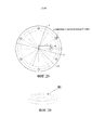
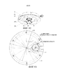
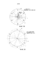
В выше отмеченном способе выполнения универсальной светодиодной лампочки диаметр стопорного кольца линзы представляет собой внешний диаметр D лампочки, внешний диаметр D лампочки и верхний предел мощности W выполненной светодиодной лампочки удовлетворяют зависимости W=1,1812е0,0361D, дискретные значения выбирают на кривой зависимости W=1,1812е0,0361D для выполнения множества светодиодных лампочек, имеющих фиксированные внешние диаметры D лампочки, так, чтобы улучшать взаимозаменяемость и универсальность светодиодных лампочек; при использовании 20 мм в качестве нижнего предела и использовании 130 мм в качестве верхнего предела внешнего диаметра D лампочки на кривой зависимости W=1,1812е0,0361D, кривую зависимости разделяют на 12 сегментов, каждый из которых устанавливают равным 10 мм, для образования ограниченного количества спецификаций внешнего диаметра лампочки, и взаимозаменяемость и универсальность светодиодных лампочек дополнительно улучшают с помощью небольшого количества спецификаций внешнего диаметра лампочки; крепежные отверстия фланца на установочном фланце стопорного кольца линзы равномерно распределяют по диаметру D1, а диаметр D1 представляет собой значение, получаемое путем вычитания диаметра крепежной винтовой гайки и далее вычитания величины 0,8-4 мм из внешнего диаметра D лампочки; диаметр D2 отверстия интерфейса радиатора светодиодной лампочки на лампе представляет собой значение, получаемое путем двукратного вычитания диаметра крепежной винтовой гайки и далее двукратного вычитания величины, соответствующей диаметру D1, из внешнего диаметра D лампочки. Интерфейс установки светодиодной лампочки включает в себя поверхность в контакте со светодиодной лампочкой и отверстие, соединенное со светодиодной лампочкой, на лампе.In the above-mentioned method for making a universal LED bulb, the diameter of the lens retaining ring is the outer diameter D of the bulb, the outer diameter D of the bulb and the upper power limit W of the made LED bulb satisfy the dependence W = 1.1812e 0.0361D , discrete values are selected on the curve of the dependence W = 1.1812e 0.0361D for making a plurality of LED bulbs having fixed outer diameters D of the bulb, so as to improve the interchangeability and versatility of the LED bulbs; when using 20 mm as the lower limit and using 130 mm as the upper limit of the outer diameter D of the bulb in the dependence curve W = 1.1812e 0.0361D , the dependence curve is divided into 12 segments, each of which is set to 10 mm, to form a limited the number of specifications of the outer diameter of the bulb, and the interchangeability and versatility of LED bulbs are further improved by using a small number of specifications of the outer diameter of the bulb; the mounting holes of the flange on the mounting flange of the lens retaining ring are evenly distributed over the diameter D1, and the diameter D1 is the value obtained by subtracting the diameter of the fastening screw nut and then subtracting the value 0.8-4 mm from the outer diameter D of the bulb; the diameter D2 of the hole of the radiator interface of the LED light bulb on the lamp is the value obtained by double subtracting the diameter of the fixing screw nut and then subtracting the value corresponding to the diameter D1 twice from the outer diameter D of the light bulb. The LED bulb installation interface includes a surface in contact with the LED bulb and an opening connected to the LED bulb on the lamp.
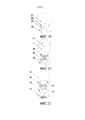
В вышеупомянутом способе выполнения универсальной светодиодной лампочки в верхней части внутреннего стопорного кольца обеспечивают уступ, цельную конструкцию, образованную путем склеивания теплопроводящего кронштейна и модуля оптического источника, приклеивают в уступе, внутреннее стопорное кольцо снаружи окружает модуль оптического источника, или между внутренним стопорным кольцом и внутренней крышкой дополнительно обеспечивают крышку внутреннего кольца, оптическую линзу распределения света приклеивают в нижней части внутреннего стопорного кольца для уплотнения модуля оптического источника в уплотненном водонепроницаемом пространстве между теплопроводящим кронштейном, внутренним стопорным кольцом и оптической линзой распределения света, или внутреннее стопорное кольцо дополнительно используют в качестве базы установки радиатора светодиодной лампочки; регулируют толщины оптической линзы распределения света, внутреннего стопорного кольца и теплопроводящего кронштейна с возможностью позволения теплопроводящему кронштейну плотно прислоняться к радиатору при установке стопорного кольца линзы; или теплопроводящий кронштейн и пластину матрицы оптического источника выполняют за одно целое из одинакового неметаллического теплопроводящего материала; или пластина матрицы оптического источника представляет собой теплопроводящую подложку из металлического материала, причем схему получают с помощью технологии платы с печатной схемой; или пластина матрицы оптического источника представляет собой теплопроводящую подложку из неметаллического материала, в которую схему встраивают с помощью технологии печатной схемы с серебряной пастой. За счет этой конструкции конструкция между чипом светодиодного источника света и радиатором является более простой, тепло, генерируемое чипом, будет быстро передаваться пластине матрицы оптического источника для рассеивания, таким образом, способствуя охлаждению светодиодного чипа и продлению срока службы светодиодного источника света.In the aforementioned method of making a universal LED light bulb, a ledge is provided at the top of the inner retaining ring, the integral structure formed by gluing the heat-conducting bracket and the optical source module is glued in the ledge, the inner retaining ring surrounds the optical source module from the outside, or between the inner retaining ring and the inner cover additionally provide an inner ring cover; an optical light distribution lens is glued to the bottom of the inner its retaining ring for sealing the optical source module in a sealed waterproof space between the heat-conducting bracket, the inner retaining ring and the optical light distribution lens, or the inner retaining ring is additionally used as a base for mounting the LED bulb radiator; adjust the thickness of the optical light distribution lens, the inner retaining ring and the heat-conducting bracket with the possibility of allowing the heat-conducting bracket to lean snugly against the radiator when installing the lens retaining ring; or the heat-conducting bracket and the matrix plate of the optical source are integrally formed from the same non-metallic heat-conducting material; or the matrix plate of the optical source is a heat-conducting substrate of metallic material, the circuit being obtained using printed circuit board technology; or the matrix plate of the optical source is a heat-conducting substrate of non-metallic material into which the circuit is embedded using printed circuit technology with silver paste. Due to this design, the construction between the chip of the LED light source and the heat sink is simpler, the heat generated by the chip will be quickly transferred to the matrix plate of the optical source for dissipation, thereby contributing to the cooling of the LED chip and the extension of the life of the LED light source.
В вышеупомянутом способе выполнения универсальной светодиодной лампочки для светодиодной лампочки небольшого размера теплопроводящий кронштейн, модуль оптического источника, внутреннее стопорное кольцо и оптическую линзу распределения света последовательно совмещают и склеивают для образования цельного элемента каркаса оптического источника светодиодной лампочки или между внутренним стопорным кольцом и внутренней крышкой дополнительно обеспечивают крышку внутреннего кольца и компоненты, загерметизированные на пластине матрицы оптического источника в модуле оптического источника, герметизируют в уплотненном водонепроницаемом пространстве между теплопроводящим кронштейном, внутренним стопорным кольцом и оптической линзой распределения света; или внутренняя крышка и внутреннее стопорное кольцо имеют цельную конструкцию (а именно, внутренняя крышка с функцией внутреннего стопорного кольца), компоненты, загерметизированные на пластине матрицы оптического источника, герметизируют в водонепроницаемом пространстве между пластиной матрицы оптического источника и цельной конструкцией, образованной внутренней крышкой и внутренним стопорным кольцом; или внутреннее стопорное кольцо дополнительно используют в качестве базы установки радиатора светодиодной лампочки; регулируют толщины оптической линзы распределения света, внутреннего стопорного кольца и теплопроводящего кронштейна с возможностью позволения теплопроводящему кронштейну плотно прислоняться к радиатору при установке стопорного кольца линзы; или теплопроводящий кронштейн и пластину матрицы оптического источника выполняют за одно целое из одинакового неметаллического теплопроводящего материала; или пластина матрицы оптического источника представляет собой теплопроводящую подложку из металлического материала, причем схему получают с помощью технологии платы с печатной схемой; или пластина матрицы оптического источника представляет собой теплопроводящую подложку из неметаллического материала, в которую схему встраивают с помощью технологии печатной схемы с серебряной пастой.In the aforementioned method of making a universal LED light bulb for a small LED light bulb, a heat-conducting bracket, an optical source module, an internal retaining ring and an optical light distribution lens are successively aligned and glued to form a solid frame member of the optical source of the LED lamp or between the internal retaining ring and the inner cover additionally provide inner ring lid and components sealed on a matrix plate s optical source in an optical source module is sealed in a waterproof sealed space between the thermally conductive holder, and inner locking ring optic light distributing lens; or the inner lid and the inner retainer ring have an integral structure (namely, the inner lid with the function of the inner retainer ring), the components sealed on the matrix plate of the optical source are sealed in a waterproof space between the matrix plate of the optical source and the integral structure formed by the inner cover and the inner retaining ring; or the inner retaining ring is additionally used as the base for installing the radiator of the LED bulb; adjust the thickness of the optical light distribution lens, the inner retaining ring and the heat-conducting bracket with the possibility of allowing the heat-conducting bracket to lean snugly against the radiator when installing the lens retaining ring; or the heat-conducting bracket and the matrix plate of the optical source are integrally formed from the same non-metallic heat-conducting material; or the matrix plate of the optical source is a heat-conducting substrate of metallic material, the circuit being obtained using printed circuit board technology; or the matrix plate of the optical source is a heat-conducting substrate of non-metallic material into which the circuit is embedded using printed circuit technology with silver paste.
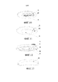
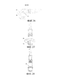
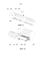
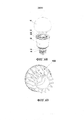
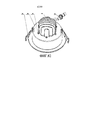
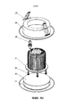
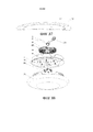
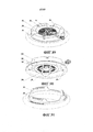
В вышеупомянутом способе выполнения универсальной светодиодной лампочки радиатор прикрепляют к теплопроводящему кронштейну и между радиатором и теплопроводящим кронштейном обеспечивают теплопроводящую прокладку; радиатор представляет собой узел неметаллического радиатора, узел неметаллического радиатора включает в себя неметаллический радиатор и теплопроводящий переходный кронштейн, неметаллический радиатор и теплопроводящий переходный кронштейн получают с помощью экструзионного формования мельчайшего неметаллического теплопроводящего материала (такого как алюминий, карбид кремния или т.п. с тонкостью менее 300 ячеек на 25,4 мм) при низкой температуре для образования формы ячейки сетки и спекания его же при высокой температуре, их контактные поверхности склеивают в единое целое путем нанесения теплопроводящего адгезива, теплопроводящий переходный кронштейн находится наверху, неметаллический радиатор принимает форму ячейки сетки, и теплопроводящий переходный кронштейн располагают сверху неметаллического радиатора для обеспечения поступления воздуха в ячейку сетки неметаллического радиатора от теплопроводящего переходного кронштейна. Отверстие для крепежного винта неметаллического радиатора заполняют резиновой оболочкой или клеем для крепления винта для присоединения крепежного винта, а снаружи неметаллического радиатора обеспечивают колпак, который могут выполнять из металлического материала путем штампования или из пластмассы путем литья под давлением, для украшения внешнего вида лампочки; или радиатор представляет собой металлический радиатор, между металлическим радиатором и теплопроводящим кронштейном обеспечивают теплопроводящую прокладку, металлический радиатор имеет полую конструкцию, полую часть заполняют пористым металлом, полую конструкцию заполняют сверхпроводящей жидкостью, верхнюю и нижнюю заглушки прижимают путем посадки с натягом или привинчивают с помощью клея для резьбового уплотнения в полой конструкции для образования уплотненного пространства и вакуумируют уплотненное пространство; крепежный винт радиатора проходит через крепежное сквозное отверстие на внутреннем стопорном кольце для того, чтобы соединяться с отверстием для крепежного винта радиатора неметаллического радиатора или металлического радиатора.In the aforementioned method of making a universal LED light bulb, a radiator is attached to a heat-conducting bracket and a heat-conducting gasket is provided between the radiator and the heat-conducting bracket; a radiator is a non-metallic radiator assembly, a non-metallic radiator assembly includes a non-metallic radiator and a heat transfer adapter, a non-metallic radiator and a heat transfer adapter are obtained by extrusion molding a finest non-metallic heat transfer material (such as aluminum, silicon carbide or the like with a fineness of less than 300 cells per 25.4 mm) at low temperature to form a mesh cell shape and sinter it at high temperature, their contact the surfaces are glued together by applying a heat-conducting adhesive, the heat-conducting adapter bracket is located at the top, the non-metallic radiator takes the form of a mesh cell, and the heat-conducting adapter bracket is placed on top of the non-metallic radiator to allow air to enter the mesh cell of the non-metallic radiator from the heat-conducting adapter bracket. The hole for the fixing screw of the non-metallic radiator is filled with a rubber sheath or glue for attaching the screw to attach the fixing screw, and on the outside of the non-metallic radiator a cap is provided that can be made of metal material by stamping or of plastic by injection molding to decorate the appearance of the bulb; or the radiator is a metal radiator, a heat-conducting gasket is provided between the metal radiator and the heat-conducting bracket, the metal radiator is hollow, the hollow part is filled with porous metal, the hollow structure is filled with superconducting liquid, the upper and lower plugs are pressed by interference fit or screwed with glue for threaded seals in a hollow structure to form a sealed space and vacuum the sealed space; the radiator mounting screw passes through the mounting through hole on the inner retaining ring in order to connect to the hole for the mounting screw of the radiator of a non-metallic radiator or metal radiator.
В вышеупомянутом способе выполнения универсальной светодиодной лампочки флуоресцентный порошок наносят распылением на светодиодный чип на модуле оптического источника, и его покрывают прозрачным силикагелем; или выполняют некоторое количество светодиодных чипов согласно пропорции синего и красного светов, необходимых для растений, и припаянный светодиодный чип покрывают только прозрачным силикагелем для герметизации; или светодиодный чип на модуле оптического источника герметизируют всего лишь прозрачным силикагелем и далее снаружи загерметизированного модуля оптического источника обеспечивают внутреннюю крышку, покрытую флуоресцентным порошком на внутренней стороне; или светодиодный чип на модуле оптического источника не покрывают силикагелем, снаружи модуля оптического источника обеспечивают вогнутую внутреннюю крышку, заполненную прозрачной изоляционной теплопроводящей жидкостью, в прозрачной изоляционной теплопроводящей жидкости обеспечивают флуоресцентный порошок, а вогнутая внутренняя крышка представляет собой упругую внутреннюю крышку тонкой внутренней вогнутой конструкции.In the aforementioned method of making a universal LED light bulb, the fluorescent powder is sprayed onto the LED chip on an optical source module and coated with transparent silica gel; or perform a number of LED chips according to the proportion of blue and red lights needed for the plants, and the soldered LED chip is coated only with transparent silica gel for sealing; or the LED chip on the optical source module is sealed with only transparent silica gel, and then on the outside of the sealed optical source module, an inner cover is coated with fluorescent powder on the inside; or the LED chip on the optical source module is not coated with silica gel, a concave inner cover filled with a transparent insulating heat-conducting liquid is provided outside the optical source module, fluorescent powder is provided in a transparent insulating heat-conducting liquid, and the concave inner cover is an elastic inner cover of a thin internal concave structure.
Флуоресцентный порошок наносят распылением на светодиодный чип на модуле оптического источника, и его покрывают прозрачным силикагелем или выполняют некоторое количество светодиодных чипов на модуле оптического источника согласно пропорции синего и красного светов, необходимых для растений, и припаянный светодиодный чип покрывают только прозрачным силикагелем; или светодиодный чип на модуле оптического источника также могут герметизировать с помощью традиционного решения герметизации, а именно флуоресцентный порошок наносят распылением на светодиодный чип и его покрывают прозрачным силикагелем, при этом не используя внутреннюю крышку; при применении настоящего изобретения для освещения в сельскохозяйственном производстве количество светодиодных чипов на модуле оптического источника выполняют согласно пропорции синего и красного светов, необходимых для растений, и припаянный светодиодный чип покрывают только прозрачным силикагелем.The fluorescent powder is sprayed onto the LED chip on the optical source module and coated with transparent silica gel, or a number of LED chips are made on the optical source module according to the proportion of blue and red lights needed for the plants, and the soldered LED chip is coated only with transparent silica gel; or the LED chip on the optical source module can also be sealed using a traditional sealing solution, namely the fluorescent powder is sprayed onto the LED chip and coated with transparent silica gel without using an inner cap; when applying the present invention for lighting in agricultural production, the number of LED chips on the optical source module is performed according to the proportion of blue and red lights needed for the plants, and the soldered LED chip is coated only with transparent silica gel.
В вышеупомянутом способе выполнения универсальной светодиодной лампочки светодиодный чип на модуле оптического источника герметизируют прозрачным силикагелем, далее снаружи загерметизированного модуля оптического источника обеспечивают внутреннюю крышку, покрытую флуоресцентным порошком на внутренней стороне, эта конструкция обеспечивает, что флуоресцентный порошок имеет более хорошую однородность по сравнению с порошком, непосредственно распыляемым на чипе, флуоресцентный порошок находится вдали от светодиодного нагревающегося чипа, светодиодный чип может работать при относительно более высокой температуре, тем самым улучшая условие работы светодиода, эффективно уменьшая световое ослабление светодиодной лампочки и обеспечивая более хороший эффект светодиодного излучения света, и дозу флуоресцентного порошка не увеличивают до большей степени; или светодиодный чип на модуле оптического источника не покрывают силикагелем, снаружи модуля оптического источника обеспечивают вогнутую внутреннюю крышку, заполненную прозрачной изоляционной теплопроводящей жидкостью, в прозрачной изоляционной теплопроводящей жидкости обеспечивают флуоресцентный порошок, а вогнутая внутренняя крышка представляет собой упругую внутреннюю крышку тонкой внутренней вогнутой конструкции, в этой конструкции при электрификации светодиода для генерирования тепла прозрачную изоляционную теплопроводящую жидкость нагревают для протекания для отведения тепла светодиодного чипа для того, чтобы обмениваться теплом с радиатором на большей площади, таким образом, исключая локальный высокий нагрев светодиодного чипа и окружающего флуоресцентного порошка в традиционном решении и эффективно уменьшая образование светового ослабления светодиода, и при нагреве прозрачной изоляционной теплопроводящей жидкости для расширения вогнутая внутренняя крышка выступает наружу для увеличения объема для приема расширенной жидкости для того, чтобы предотвращать расширение жидкости от приведения к неэффективному уплотнению внутренней крышки.In the aforementioned method of making a universal LED light bulb, the LED chip on the optical source module is sealed with transparent silica gel, then the outside of the sealed optical source module is provided with an inner lid coated with fluorescent powder on the inside, this design ensures that the fluorescent powder has better uniformity compared to the powder, directly sprayed onto the chip, the fluorescent powder is away from the LED heating Xia chip, the LED chip may operate at a relatively higher temperature, thereby improving the LED operation condition, effectively reducing light attenuation of the LED light and providing a good effect of the LED light emission and a fluorescent powder dose not increase to a greater extent; or the LED chip on the optical source module is not coated with silica gel, the outside of the optical source module is provided with a concave inner cover filled with a transparent insulating heat-conducting liquid, fluorescent powder is provided in a transparent insulating heat-conducting liquid, and the concave inner cover is an elastic inner cover of a thin internal concave structure, in this design when electrifying the LED to generate heat transparent insulation heat conduit The clear fluid is heated to allow the heat of the LED chip to be removed in order to exchange heat with the heat sink over a larger area, thereby eliminating local high heating of the LED chip and the surrounding fluorescent powder in a traditional solution and effectively reducing the formation of light attenuation of the LED, and when heating is transparent the insulating heat transfer fluid for expansion the concave inner cover protrudes outward to increase the volume for receiving the expanded fluid so that Prevents fluid expansion from driving an inefficient seal of the inner lid.
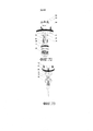
В вышеупомянутом способе выполнения универсальной светодиодной лампочки крепежное отверстие штепселя соединителя прикрепляют к теплопроводящему кронштейну, штепсель соединителя с контактным штырем вставляют в крепежное отверстие штепселя соединителя и закрепляют с частью, вставленной в лампочку, в качестве закрепленного конца, задний конец контактного штыря припаивают к пластине матрицы оптического источника в универсальной светодиодной лампочке для образования простого электрического интерфейса на внешней поверхности универсальной светодиодной лампочки, во время установки при условии, что штепсель соединителя находится в стыковом соединении с розеткой соединителя с кабелем, а универсальная светодиодная лампочка является закрепленной, достигают электрического соединения универсальной светодиодной лампочки; положение эксцентриситета отверстия штепселя соединителя на теплопроводящем кронштейне и размер закрепленного конца штепселя соединителя ограничивают так, что пластина матрицы оптического источника в светодиодной лампочке может удовлетворять требованиям размещения светодиодного чипа и чипа возбуждения источника питания и требованию выравнивания; штепсель соединителя с контактным штырем имеет четырехштырьковую конструкцию, причем два штыря используют для ввода к источнику питания, а другие два штыря используют для ввода управления; закрепленный конец закрепляют путем крепления гайкой или путем способа фиксации кольцевой пайкой; при закреплении закрепленного конца путем крепления гайкой между штепселем соединителя и теплопроводящим кронштейном добавляют водонепроницаемое резиновое кольцо для предотвращения протекания воды; для того, чтобы предотвращать вращение, противоскользящую выемку прикрепляют к штепселю соединителя и в сквозном отверстии теплопроводящего кронштейна обеспечивают соответствующий выступ; фланец с тремя отверстиями прикрепляют к розетке соединителя и закрепляют на радиаторе лампы с помощью крепежного винта, и между розеткой соединителя и радиатором обеспечивают регулировочную резиновую прокладку для регулирования толщины для того, чтобы обеспечивать герметичность водонепроницаемой поверхности; или внешние резьбы прикрепляют к штепселю электрического соединителя для соответствия внутренним резьбам крепежной гайки на розетке соединителя, обеспеченной водонепроницаемым резиновым кольцом для предотвращения протекания воды; щель прикрепляют к розетке соединителя, и в щели обеспечивают водонепроницаемое резиновое кольцо для предотвращения протекания воды.In the aforementioned method for making a universal LED light bulb, the mounting hole of the connector plug is attached to the heat-conducting bracket, the connector plug with the contact pin is inserted into the mounting hole of the connector plug and fixed with the part inserted into the light bulb as a fixed end, the rear end of the contact pin is soldered to the optical matrix plate a source in a universal LED light bulb to form a simple electrical interface on the outer surface of the univers Flax LED light bulb, while setting the condition that the connector plug is in a butt joint with the socket connector to the cable, and the universal LED lamp is fixed, the electrical connection is achieved universal LED bulbs; the position of the eccentricity of the hole of the connector plug on the heat-conducting bracket and the size of the fixed end of the connector plug are limited so that the plate of the matrix of the optical source in the LED bulb can satisfy the requirements for the placement of the LED chip and the excitation chip of the power source and alignment requirement; the connector plug with the contact pin has a four-pin design, wherein two pins are used for input to a power source, and the other two pins are used for control input; the fixed end is fixed by fastening with a nut or by a method of fixing with ring soldering; when securing the fixed end by fastening with a nut between the connector plug and the heat-conducting bracket, add a waterproof rubber ring to prevent water leakage; in order to prevent rotation, the anti-slip recess is attached to the connector plug and a corresponding protrusion is provided in the through hole of the heat-conducting bracket; a three-hole flange is attached to the socket of the connector and secured to the lamp radiator by means of a fixing screw, and between the socket of the connector and the radiator an adjustment rubber gasket is provided to adjust the thickness in order to ensure the tightness of the waterproof surface; or external threads are attached to the plug of the electrical connector to match the internal threads of the fastening nut on the socket of the connector provided with a waterproof rubber ring to prevent water from leaking; the slot is attached to the connector receptacle, and a waterproof rubber ring is provided in the slots to prevent water from leaking.
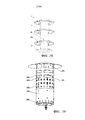
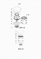
Светодиодная лампочка, имеющая конструкцию стопорного кольца, выполненная вышеупомянутым способом, включает в себя стопорное кольцо линзы с установочным фланцем, причем по меньшей мере теплопроводящий кронштейн, модуль оптического источника, внутреннее стопорное кольцо и оптическая линза распределения света последовательно обеспечены в стопорном кольце линзы, причем верхний конец внутреннего стопорного кольца склеен с теплопроводящим кронштейном, нижний конец внутреннего стопорного кольца склеен с оптической линзой распределения света так, что уплотненное водонепроницаемое пространство для заключения модуля оптического механизма образовано внутренним стопорным кольцом, теплопроводящим кронштейном и оптической линзой распределения света; причем штепсель соединителя закреплен на теплопроводящем кронштейне, а снаружи модуля оптического источника дополнительно обеспечена внутренняя крышка; модуль оптического источника составлен из пластины матрицы оптического источника, набора светодиодных чипов и соответствующей проводки путем пайки и герметизации или в него дополнительно встроен чип для возбуждения источника питания.An LED bulb having a retainer ring structure made by the aforementioned method includes a lens retainer ring with a mounting flange, at least a heat-conducting bracket, an optical source module, an inner retainer ring and an optical light distribution lens are sequentially provided in the lens retainer ring, the upper the end of the inner retaining ring is glued with a heat-conducting bracket, the lower end of the inner retaining ring is glued with an optical distribution lens light so that the sealed waterproof space for enclosing the module of the optical mechanism is formed by an internal retaining ring, a heat-conducting bracket and an optical light distribution lens; moreover, the connector plug is mounted on a heat-conducting bracket, and an inner cover is additionally provided outside the optical source module; the optical source module is composed of a matrix plate of the optical source, a set of LED chips and the corresponding wiring by soldering and sealing, or an additional chip is built into it to excite the power source.
В вышеупомянутой светодиодной лампочке, имеющей конструкцию стопорного кольца, в верхней части внутреннего стопорного кольца обеспечен уступ, в уступе обеспечен теплопроводящий кронштейн, модуль оптического источника приклеен на теплопроводящем кронштейне, внутреннее стопорное кольцо снаружи окружает модуль оптического источника, или между внутренним стопорным кольцом и внутренней крышкой дополнительно обеспечена крышка внутреннего кольца; или внутреннее стопорное кольцо дополнительно используется в качестве базы установки радиатора светодиодной лампочки; при установке стопорного кольца линзы может быть обеспечено, что верхняя поверхность теплопроводящего кронштейна плотно прислоняется к радиатору; или теплопроводящий кронштейн и пластина матрицы оптического источника выполнены за одно целое из одинакового неметаллического теплопроводящего материала; или пластина матрицы оптического источника представляет собой теплопроводящую подложку из металлического материала, причем схема получена с помощью технологии платы с печатной схемой; или пластина матрицы оптического источника представляет собой теплопроводящую подложку из неметаллического материала, в которую схема встроена с помощью. технологии печатной схемы с серебряной пастой.In the aforementioned LED light bulb having a retaining ring structure, a step is provided in the upper part of the inner retaining ring, a heat conducting bracket is provided in the ledge, the optical source module is glued to the heat conducting bracket, the inner retaining ring surrounds the optical source module from the outside, or between the inner retaining ring and the inner cover an inner ring cap is additionally provided; or the inner retaining ring is additionally used as the base for installing the LED bulb radiator; when installing the lens retaining ring, it can be ensured that the upper surface of the heat-conducting bracket is leaning against the radiator; or the heat-conducting bracket and the matrix plate of the optical source are made integrally from the same non-metallic heat-conducting material; or the matrix plate of the optical source is a heat-conducting substrate of metallic material, the circuit obtained using printed circuit board technology; or the matrix plate of the optical source is a heat-conducting substrate of non-metallic material into which the circuit is embedded with. technology printed circuit with silver paste.
В вышеупомянутой светодиодной лампочке, имеющей конструкцию стопорного кольца, для светодиодной лампочки небольшого размера теплопроводящий кронштейн, модуль оптического источника, внутреннее стопорное кольцо и оптическая линза распределения света последовательно совмещены и склеены, или между внутренним стопорным кольцом и внутренней крышкой дополнительно обеспечена крышка внутреннего кольца, и пластина матрицы оптического источника модуля оптического источника, внутреннее стопорное кольцо и оптическая линза распределения света образуют уплотненное водонепроницаемое пространство, используемое для герметизации компонентов, загерметизированных на пластине матрицы оптического источника; или внутреннее стопорное кольцо дополнительно используется в качестве базы установки радиатора светодиодной лампочки; или внутреннее стопорное кольцо и внутренняя крышка переработаны во внутреннюю крышку, имеющую функцию внутреннего стопорного кольца и имеющую цельную конструкцию; при установке стопорного кольца линзы можно обеспечивать, что верхняя поверхность теплопроводящего кронштейна плотно прислоняется к радиатору; или теплопроводящий кронштейн и пластина матрицы оптического источника выполнены за одно целое из одинакового неметаллического теплопроводящего материала; или пластина матрицы оптического источника представляет собой теплопроводящую подложку из металлического материала, причем схема получена с помощью технологии платы с печатной схемой; или пластина матрицы оптического источника представляет собой теплопроводящую подложку из неметаллического материала, в которую схема встроена с помощью технологии печатной схемы с серебряной пастой.In the aforementioned LED light bulb having a retainer ring design, for a small LED light bulb, a heat-conducting bracket, an optical source module, an inner retainer ring and an optical light distribution lens are successively aligned and glued, or an inner ring cover is further provided between the inner retainer ring and the inner cover, and the matrix plate of the optical source of the optical source module, the inner retaining ring and the optical distribution lens and form a sealed watertight space used for sealing components on the plate sealed optical source matrix; or the inner retaining ring is additionally used as the base for installing the LED bulb radiator; or the inner retaining ring and inner lid are processed into an inner lid having the function of an inner retaining ring and having a one-piece structure; when installing the lens retaining ring, it can be ensured that the upper surface of the heat-conducting bracket is leaning against the radiator; or the heat-conducting bracket and the matrix plate of the optical source are made integrally from the same non-metallic heat-conducting material; or the matrix plate of the optical source is a heat-conducting substrate of metallic material, the circuit obtained using printed circuit board technology; or the matrix plate of the optical source is a heat-conducting substrate of non-metallic material into which the circuit is embedded using a printed circuit technology with silver paste.
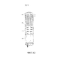
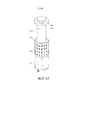
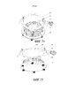
В вышеупомянутой светодиодной лампочке, имеющей конструкцию стопорного кольца, радиатор прикреплен к теплопроводящему кронштейну; радиатор представляет собой узел неметаллического радиатора, узел неметаллического радиатора включает в себя неметаллический радиатор и верхний теплопроводящий переходный кронштейн на его нижней стороне, отверстие для крепежного винта радиатора неметаллического радиатора заполнено резиновой оболочкой или клеем для крепления винта для присоединения крепежного винта, а снаружи неметаллического радиатора обеспечен колпак; или радиатор представляет собой металлический радиатор, между металлическим радиатором и теплопроводящим кронштейном обеспечена теплопроводящая прокладка, металлический радиатор включает в себя охлаждающее ребро, в средней части охлаждающего ребра обеспечена полость для сверхпроводящей текучей среды, полость для сверхпроводящей текучей среды заполнена пористым металлом, и она заполнена сверхпроводящей текучей средой, на двух концах полости для сверхпроводящей текучей среды обеспечены верхняя заглушка и нижняя заглушка, и вакуум-отсосная труба прикреплена к верхней заглушке или нижней заглушке; отверстие для кабеля, используемое для прохода кабеля, и отверстие для крепежного винта радиатора дополнительно прикреплены к радиатору. Крепежный винт радиатора проходит через крепежное сквозное отверстие радиатора на внутреннем стопорном кольце для соединения с отверстием для крепежного винта радиатора неметаллического радиатора или металлического радиатора.In the aforementioned LED light bulb having a retaining ring structure, a radiator is attached to a heat-conducting bracket; the radiator is a non-metallic radiator assembly, the non-metallic radiator assembly includes a non-metallic radiator and an upper heat-conducting adapter bracket on its lower side, the hole for the fixing screw of the non-metallic radiator is filled with a rubber sheath or glue for attaching the screw to attach the fixing screw, and the outside of the non-metallic radiator is provided cap; or the radiator is a metal radiator, a heat-conducting gasket is provided between the metal radiator and the heat-conducting bracket, the metal radiator includes a cooling fin, a cavity for the superconducting fluid is provided in the middle of the cooling fin, the cavity for the superconducting fluid is filled with porous metal, and it is filled with superconducting fluid, at the two ends of the cavity for the superconducting fluid, an upper plug and a lower plug are provided, and a vacuum tsosnaya pipe attached to the top cap or bottom plug; the cable hole used to pass the cable and the hole for the radiator fixing screw are additionally attached to the radiator. The radiator mounting screw passes through the radiator mounting through hole on the inner retainer ring to connect to the hole for the radiator mounting screw of the non-metal radiator or metal radiator.
Снаружи светодиодного чипа на модуле оптического источника обеспечен только прозрачный силикагель для герметизации, снаружи модуля оптического источника с прозрачным силикагелем прикреплена внутренняя крышка, и покрытие из флуоресцентного порошка обеспечено к внутреннему слою внутренней крышки; или светодиодный чип на модуле оптического источника не загерметизирован силикагелем, снаружи модуля оптического источника обеспечена вогнутая внутренняя крышка, заполненная прозрачной изоляционной теплопроводящей жидкостью, светодиодный чип на модуле оптического источника погружен в прозрачную изоляционную теплопроводящую жидкость, в прозрачной изоляционной теплопроводящей жидкости обеспечен флуоресцентный порошок, а вогнутая внутренняя крышка представляет собой упругую внутреннюю крышку тонкой внутренней вогнутой конструкции.On the outside of the LED chip on the optical source module, only transparent silica gel is provided for sealing, on the outside of the optical source module with transparent silica gel an inner cover is attached, and a coating of fluorescent powder is provided to the inner layer of the inner cover; or the LED chip on the optical source module is not sealed with silica gel, a concave inner cover is provided on the outside of the optical source module filled with a transparent insulating heat-conducting liquid, the LED chip on the optical source module is immersed in a transparent insulating heat-conducting liquid, a fluorescent powder is provided in the transparent insulating heat-conducting liquid, and the concave the inner lid is an elastic inner lid of a thin inner concave structure ui.
В вышеупомянутой светодиодной лампочке, имеющей конструкцию стопорного кольца, электрический соединитель прикреплен к теплопроводящему кронштейну, электрический соединитель включает в себя штепсель электрического соединителя, контактный штырь обеспечен к штепселю электрического соединителя, а кромка контактного штыря на наконечнике контактного штыря припаяна к модулю оптического источника; после прохода через крепежное отверстие штепселя электрического соединителя на универсальной светодиодной лампочке штепсель соединителя обеспечен закрепленным концом для крепления; штепсель соединителя взаимно соединен с розеткой соединителя с гнездом, а розетка соединителя соединена с кабелем; контактный штырь электрического соединителя имеет четырехштырьковую конструкцию, причем два штыря используются для ввода к источнику питания, а другие два штыря используются для ввода управления.In the aforementioned LED light bulb having a snap ring design, an electrical connector is attached to a heat-conducting bracket, an electrical connector includes an electrical connector, a contact pin is provided to an electrical connector, and the edge of the contact pin on the tip of the contact pin is soldered to the optical source module; after passing through the mounting hole of the plug of the electrical connector on the universal LED light bulb, the plug of the connector is provided with a fixed end for mounting; the connector plug is mutually connected to the socket of the connector with the socket, and the socket of the connector is connected to the cable; the contact pin of the electrical connector has a four-pin design, with two pins used for input to a power source, and the other two pins used for input control.
В вышеупомянутой светодиодной лампочке, имеющей конструкцию стопорного кольца, закрепленный конец представляет собой плавильное кольцо; или закрепленный конец представляет собой крепежную гайку, щель для водонепроницаемого резинового кольца дополнительно прикреплена к штепселю соединителя, а в щели для водонепроницаемого резинового кольца обеспечено водонепроницаемое резиновое кольцо; для того, чтобы предотвращать вращение, противоскользящая выемка прикреплена к штепселю соединителя, а в сквозном отверстии теплопроводящего кронштейна обеспечен соответствующий выступ; фланец с тремя отверстиями обеспечен к розетке соединителя, а розетка соединителя прикреплена к радиатору или теплопроводящей преобразовательной пластине на лампе с помощью фланца с тремя отверстиями и крепежного винта розетки соединителя, и между фланцем и радиатором или теплопроводящей преобразовательной пластиной на лампе обеспечена закрепленная регулировочная резиновая прокладка для обеспечения герметичности водонепроницаемой поверхности; или штепсель соединителя обеспечен внешними резьбами для соответствия внутренним резьбам крепежной гайки на розетке соединителя, обеспеченной водонепроницаемым резиновым кольцом так, чтобы прикрепляться к штепселю соединителя; щель прикреплена к розетке соединителя, и в щели обеспечено водонепроницаемое резиновое кольцо.In the aforementioned LED light bulb having a retaining ring structure, the fixed end is a melting ring; or the fixed end is a fastening nut, the slot for the waterproof rubber ring is additionally attached to the connector plug, and a waterproof rubber ring is provided in the slot for the waterproof rubber ring; in order to prevent rotation, the anti-slip recess is attached to the connector plug, and a corresponding protrusion is provided in the through hole of the heat-conducting bracket; a flange with three holes is provided to the socket of the connector, and the socket of the connector is attached to the radiator or heat-conducting conversion plate on the lamp with a flange with three holes and the fixing screw of the socket of the connector, and a fixed adjusting rubber gasket is provided between the flange and the radiator or heat-conducting conversion plate on the lamp for ensuring tightness of a waterproof surface; or the connector plug is provided with external threads to match the internal threads of the mounting nut on the connector receptacle provided with a waterproof rubber ring so as to be attached to the connector plug; the slot is attached to the socket of the connector, and a waterproof rubber ring is provided in the slot.
Согласно другому аспекту настоящее изобретение дополнительно обеспечивает множество ламп, использующих вышеупомянутую светодиодную лампочку. Лампа, обеспеченная настоящим изобретением, имеет простую конструкцию, низкую стоимость изготовления, быстро, дешево и удобно устанавливается, используется и обслуживается, и маловероятно расширяет выход из строя, достигает независимого производства и использования лампочки, лампы и изделия для управления освещением светодиодной лампочки, значительно уменьшает процедуры производства, достигает массового производства и облегчает применение и производство в промышленном масштабе светодиодных энергосберегающих осветительных изделий.According to another aspect, the present invention further provides a plurality of lamps using the aforementioned LED light bulb. The lamp provided by the present invention has a simple structure, low manufacturing cost, quickly, cheaply and conveniently installed, used and maintained, and is unlikely to expand failure, achieve independent production and use of a light bulb, lamp and product for controlling the lighting of an LED light bulb, significantly reduces production procedures, reaches mass production and facilitates the application and industrial production of LED energy-saving lighting products .
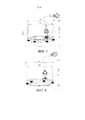
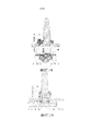
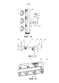
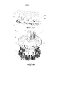
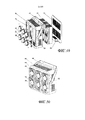
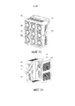
Светодиодная туннельная лампа, использующая конструкцию двустороннего радиатора, включает в себя двусторонний радиатор экструзионного типа, образованный экструзией металла, причем светодиодная лампочка прикреплена к двустороннему радиатору экструзионного типа, двусторонний радиатор экструзионного типа установлен на опоре для установки, и интерфейс установки, используемый для установки светодиодной лампочки, прикреплен к двустороннему радиатору экструзионного типа.The LED tunnel lamp using the double-sided radiator design includes a double-sided extrusion type radiator formed by metal extrusion, the LED bulb being attached to the double-sided extrusion type radiator, the double-sided extrusion type radiator mounted on a support for installation, and the installation interface used to install the LED bulb attached to a double sided extrusion type radiator.
В вышеупомянутой светодиодной туннельной лампе, использующей конструкцию двустороннего радиатора, двусторонний радиатор экструзионного типа включает в себя подложку, и на двух сторонах подложки обеспечены ребра. На одной стороне подложки обеспечен интерфейс установки, используемый для установки светодиодной лампочки, и круглые или эллиптические конические пространства образованы путем подрезания ребер около интерфейса установки подложки согласно углу освещения света, излучаемого лампочкой, вплоть до того, чтобы не заслонять свет, излучаемый светодиодной лампочкой; интерфейс установки включает в себя поверхность в контакте со светодиодной лампочкой и отверстие, соединенное со светодиодной лампочкой, на двустороннем радиаторе экструзионного типа; светодиодная туннельная лампа, использующая конструкцию двустороннего радиатора, дополнительно включает в себя соединитель пучка проводов, и соединитель пучка проводов используется для соединения множества светодиодных лампочек с источником питания и схемой управления.In the aforementioned LED tunnel lamp using a double-sided radiator design, an extrusion-type double-sided radiator includes a substrate, and fins are provided on two sides of the substrate. On one side of the substrate, an installation interface is provided for installing the LED light bulb, and circular or elliptical conical spaces are formed by cutting edges near the installation interface of the substrate according to the angle of illumination of the light emitted by the light bulb, up to not obscuring the light emitted by the LED light bulb; the installation interface includes a surface in contact with the LED bulb and an opening connected to the LED bulb on a double-sided extrusion-type radiator; an LED tunnel lamp using a double-sided radiator design further includes a wire bundle connector, and a wire bundle connector is used to connect a plurality of LED bulbs to a power source and a control circuit.
В вышеупомянутой светодиодной туннельной лампе, использующей конструкцию двустороннего радиатора, двусторонний радиатор экструзионного типа установлен на опоре для установки с помощью поворотной соединительной пластины; поворотная соединительная пластина закреплена на отводном кронштейне, а отводной кронштейн закреплен на опоре для установки так, что угол двустороннего радиатора экструзионного типа может одновременно регулироваться в горизонтальном направлении и вертикальном направлении; соединитель пучка проводов прикреплен к опоре для установки.In the aforementioned LED tunnel lamp using a double-sided radiator design, an extrusion-type double-sided radiator is mounted on a support for installation by a rotatable connecting plate; a rotatable connecting plate is fixed to the outlet bracket, and the outlet bracket is fixed to the support for installation so that the angle of the extrusion-type double-sided radiator can be simultaneously adjusted in the horizontal direction and the vertical direction; the bundle of wires is attached to the support for installation.
В вышеупомянутой светодиодной туннельной лампе, использующей конструкцию двустороннего радиатора, или двусторонний радиатор экструзионного типа соединен с кронштейном для радиатора; кронштейн для радиатора используется для установки двустороннего радиатора на опоре для установки с помощью поворотной соединительной пластины, кронштейн для радиатора соединен с поворотной соединительной пластиной, поворотная соединительная пластина закреплена на отводном кронштейне, а отводной кронштейн закреплен на опоре для установки так, что угол двустороннего радиатора экструзионного типа может одновременно регулироваться в горизонтальном направлении и вертикальном направлении; соединитель пучка проводов прикреплен к кронштейну для радиатора.In the aforementioned LED tunnel lamp using a double-sided radiator design, or an extrusion-type double-sided radiator is connected to a radiator bracket; the radiator bracket is used to mount the double-sided radiator on the support for installation with a rotary connecting plate, the radiator bracket is connected to the rotary connecting plate, the rotary connecting plate is fixed to the outlet bracket, and the outlet bracket is fixed to the mounting bracket so that the angle of the extrusion double-sided radiator type can be simultaneously adjusted in horizontal direction and vertical direction; the wire bundle connector is attached to the radiator bracket.
В вышеупомянутой светодиодной туннельной лампе, использующей конструкцию двустороннего радиатора, поворотная запирающая выемка опоры для установки вырезана на опоре для установки, после регулирования угла освещения лампы крепежный винт для вращения опоры для установки (винт используется для запирания лампы в направлении силы тяжести для предотвращения ослабления) и крепежный винт отводного кронштейна могут быть привинчены, при этом поворотный запирающий винт опоры для установки привинчен в поворотной запирающей выемке опоры для установки для предотвращения изменения направления освещения. Угол освещения может одновременно регулироваться в горизонтальном и вертикальном направлениях путем регулирования крепежного винта отводного кронштейна и крепежного винта для вращения опоры для установки.In the aforementioned LED tunnel lamp using a double-sided radiator design, the rotary locking recess of the mounting support is cut out on the mounting support, after adjusting the angle of illumination of the lamp, the mounting screw to rotate the mounting support (the screw is used to lock the lamp in the direction of gravity to prevent loosening) and the mounting bracket of the outlet bracket can be screwed, while the rotary locking screw of the mounting support is screwed into the rotating locking recess of the supporting bracket for anovki to prevent changes in the illumination direction. The angle of illumination can be simultaneously adjusted in horizontal and vertical directions by adjusting the mounting screw of the outlet bracket and the mounting screw to rotate the support for installation.
В вышеупомянутой светодиодной туннельной лампе, использующей конструкцию двустороннего радиатора, шесть крепежных отверстий фланца на интерфейсе установки двустороннего радиатора экструзионного типа равномерно распределены по диаметру D1, а диаметр D1 представляет собой значение, получаемое путем вычитания диаметра крепежной винтовой гайки и далее вычитания величины 0,8-4 мм из внешнего диаметра D светодиодной лампочки.In the aforementioned LED tunnel lamp using a double-sided radiator design, the six mounting holes of the flange on the installation interface of the double-sided extrusion-type radiator are uniformly distributed over the diameter D1, and the diameter D1 is the value obtained by subtracting the diameter of the fixing screw nut and then subtracting the value 0.8- 4 mm of the outer diameter D of the LED bulb.
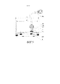
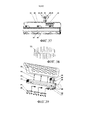
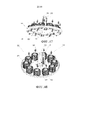
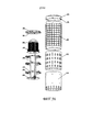
Светодиодная уличная лампа, использующая конструкцию радиатора экструзионного типа, включает в себя радиатор экструзионного типа, образованный экструзией металла, причем интерфейс установки прикреплен к радиатору экструзионного типа, а светодиодная лампочка прикреплена к интерфейсу установки; радиатор экструзионного типа установлен на подставке для лампы; колпак, образованный выдавливанием из металла или отлитый под давлением из пластмассы, обеспечен снаружи радиатора экструзионного типа; Светодиодная уличная лампа, использующая конструкцию радиатора экструзионного типа, дополнительно включает в себя соединитель пучка проводов, и соединитель пучка проводов используется для соединения множества светодиодных лампочек с источником питания и схемой управления.An LED street lamp using an extrusion-type radiator design includes an extrusion-type radiator formed by metal extrusion, the installation interface being attached to the extrusion-type radiator, and the LED lamp attached to the installation interface; extrusion type radiator mounted on a lamp stand; a cap formed by extrusion from metal or molded from plastic is provided outside the extrusion type radiator; An LED street lamp using an extrusion-type radiator design further includes a wire bundle connector, and a wire bundle connector is used to connect a plurality of LED bulbs to a power source and a control circuit.
В вышеупомянутой светодиодной уличной лампе, использующей конструкцию радиатора экструзионного типа, радиатор экструзионного типа включает в себя подложку, на одной стороне подложки обеспечены ребра, и отверстие для кабеля обеспечено к подложке; на другой стороне подложки обеспечен интерфейс установки, используемый для установки светодиодной лампочки; кронштейн для проводящего провода обеспечен на стороне с ребрами подложки, и кронштейн для проводящего провода используется для соединения проводящего провода, выходящего из светодиодной лампочки, с соединителем пучка проводов; интерфейс установки включает в себя поверхность в контакте со светодиодной лампочкой и отверстие, соединенное со светодиодной лампочкой, на радиаторе экструзионного типа.In the aforementioned LED street lamp using an extrusion-type radiator design, the extrusion-type radiator includes a substrate, ribs are provided on one side of the substrate, and a cable hole is provided to the substrate; on the other side of the substrate, an installation interface is provided, used to install the LED bulb; a bracket for the conductive wire is provided on the side with the ribs of the substrate, and a bracket for the conductive wire is used to connect the conductive wire exiting from the LED light bulb to the wire bundle connector; The installation interface includes a surface in contact with the LED bulb and an opening connected to the LED bulb on an extrusion-type radiator.
В вышеупомянутой светодиодной уличной лампе, использующей конструкцию радиатора экструзионного типа, одна сторона подложки радиатора экструзионного типа соединена с L-образной соединительной пластиной, а L-образная соединительная пластина соединена с подставкой для лампы. Соединитель пучка проводов прикреплен к радиатору экструзионного типа.In the aforementioned LED street lamp using an extrusion-type radiator design, one side of the extrusion-type radiator substrate is connected to an L-shaped connection plate, and the L-shaped connection plate is connected to the lamp stand. The wire bundle connector is attached to an extrusion type radiator.
В вышеупомянутой светодиодной уличной лампе, использующей конструкцию радиатора экструзионного типа, отверстие для установки кронштейна прикреплено к подложке или центру радиатора экструзионного типа, и радиатор экструзионного типа закреплен на подставке для лампы с помощью крепежного болта для установки уличной лампы посредством отверстия для установки кронштейна и крепежного кольца подставки для лампы; соединитель пучка проводов обеспечен в подставке для лампы, соединенной с радиатором экструзионного типа.In the aforementioned LED street lamp using an extrusion-type radiator design, the bracket mounting hole is fixed to the substrate or center of the extrusion-type radiator, and the extrusion-type radiator is fixed to the lamp stand using a mounting bolt to install the street lamp by the bracket mounting hole and the mounting ring stands for the lamp; a wire bundle connector is provided in a lamp stand connected to an extrusion-type radiator.
В вышеупомянутой светодиодной уличной лампе, использующей конструкцию радиатора экструзионного типа, шесть крепежных отверстий фланца на интерфейсе установки равномерно распределены по диаметру D1, а диаметр D1 представляет собой значение, получаемое путем вычитания диаметра крепежной винтовой гайки и далее вычитания величины 0,8-4 мм из внешнего диаметра D светодиодной лампочки.In the aforementioned LED street lamp using an extrusion-type radiator design, the six mounting holes of the flange on the installation interface are uniformly distributed over the diameter D1, and the diameter D1 is the value obtained by subtracting the diameter of the fixing screw nut and then subtracting the value 0.8-4 mm from outer diameter D of the LED bulb.
Светодиодная проекционная лампа, использующая колпак в качестве конструкции кронштейна интерфейса установки, включает в себя колпак, образованный выдавливанием из листового металла с помощью процесса штампования, причем интерфейс установки прикреплен к колпаку, светодиодная лампочка, обеспеченная радиатором, прикреплена к интерфейсу установки, средняя часть колпака соединена с крепежной муфтой подставки для лампы с помощью крепежного элемента подставки для лампы, а в нижней части колпака обеспечена декоративная крышка.The LED projection lamp using the cap as the structure of the installation interface bracket includes a cap formed by extruding from sheet metal by a stamping process, the installation interface being attached to the cap, the LED bulb provided with a radiator attached to the installation interface, the middle part of the cap connected with the mounting bracket for the lamp stand using the lamp stand fixing element, and a decorative cover is provided at the bottom of the cap.
В вышеупомянутой светодиодной проекционной лампе, использующей колпак в качестве конструкции кронштейна интерфейса установки, колпак является круглым, около крепежной муфты подставки для лампы в верхней части центра колпака обеспечена группа круглых кольцеобразных интерфейсов установки, а на краю колпака для усиления конструктивной прочности обеспечен краевой отгиб; декоративная крышка обеспечена в центре нижней части колпака; интерфейс установки включает в себя поверхность в контакте со светодиодной лампочкой и отверстие, соединенное со светодиодной лампочкой, на колпаке; соединитель пучка проводов прикреплен к крепежной муфте подставки для лампы, и соединитель пучка проводов используется для соединения множества светодиодных лампочек с источником питания и схемой управления.In the aforementioned LED projection lamp, using the cap as the design of the mounting bracket of the installation interface, the cap is round, a group of round ring-shaped installation interfaces is provided at the top of the center of the cap near the lamp stand mounting bracket, and an edge bend is provided at the edge of the cap to enhance structural strength; a decorative cover is provided in the center of the lower part of the hood; the installation interface includes a surface in contact with the LED bulb and an opening connected to the LED bulb on the cap; a wire bundle connector is attached to a lamp stand mounting sleeve, and a wire bundle connector is used to connect a plurality of LED bulbs to a power source and a control circuit.
В вышеупомянутой светодиодной проекционной лампе, использующей колпак в качестве конструкции кронштейна интерфейса установки, крепежный элемент подставки для лампы включает в себя фланец крепежной муфты, болт крепежной муфты подставки для лампы и усиливающую пластину; крепежная муфта подставки для лампы неподвижно соединена с колпаком с помощью фланца крепежной муфты, болта крепежной муфты подставки для лампы и усиливающей пластины.In the aforementioned LED projection lamp using the cap as the structure of the mounting bracket of the installation interface, the lamp stand fastener includes a flange of a fastener, a bolt of a fastener of the lamp stand and a reinforcing plate; the lamp holder mounting sleeve is fixedly connected to the cap using the mounting sleeve flange, lamp holder mounting sleeve bolt, and reinforcing plate.
В вышеупомянутой светодиодной проекционной лампе, использующей корпус лампы в качестве конструкции кронштейна интерфейса установки, шесть крепежных отверстий фланца и отверстие интерфейса радиатора прикреплены к интерфейсу установки, крепежные отверстия фланца используются для крепления светодиодной лампочки, а отверстие интерфейса радиатора используется для обеспечения прохода радиатора светодиодной лампочки через интерфейс установки лампочки; крепежные отверстия фланца равномерно распределены по диаметру D1, а диаметр D1 представляет собой значение, получаемое путем вычитания диаметра крепежной винтовой гайки и далее вычитания величины 0,8-4 мм из внешнего диаметра D светодиодной лампочки; диаметр D2 отверстия интерфейса радиатора на интерфейсе установки представляет собой значение, получаемое путем двукратного вычитания диаметра крепежной винтовой гайки и далее двукратного вычитания величины, соответствующей диаметру D1, из внешнего диаметра D лампочки.In the aforementioned LED projection lamp using the lamp housing as the mounting structure of the installation interface bracket, six mounting holes of the flange and a hole of the radiator interface are attached to the installation interface, mounting holes of the flange are used to mount the LED bulb, and the hole of the radiator interface is used to allow the radiator of the LED bulb to pass through light installation interface; the mounting holes of the flange are uniformly distributed over the diameter D1, and the diameter D1 is the value obtained by subtracting the diameter of the fastening screw nut and then subtracting the value of 0.8-4 mm from the outer diameter D of the LED bulb; the diameter D2 of the hole of the radiator interface on the installation interface is the value obtained by double subtracting the diameter of the fastening screw nut and then subtracting the value corresponding to the diameter D1 twice from the outer diameter D of the bulb.
Светодиодная проекционная лампа, использующая колпак в качестве конструкции кронштейна интерфейса установки, включает в себя колпак и светодиодную лампочку, причем колпак представляет собой прямоугольный блок с открытой поверхностью, в колпаке обеспечен двусторонний радиатор экструзионного типа, отверстие, используемое для установки двустороннего радиатора экструзионного типа, прикреплено к поверхности, противоположной отверстию кронштейна корпуса лампы, вентиляционные отверстия прикреплены к поверхностям, отличным от открытой поверхности и поверхности, обеспеченной отверстием колпака, и колпак установлен и закреплен с помощью крепежных узлов, обеспеченных на двух сторонах; интерфейс установки, используемый для установки светодиодной лампочки, прикреплен к двустороннему радиатору экструзионного типа.The LED projection lamp using the cap as the design of the mounting bracket of the installation interface includes a cap and an LED bulb, and the cap is a rectangular block with an open surface, a double-sided extrusion radiator is provided in the cap, the hole used to install a double-sided extrusion type radiator is attached to the surface opposite the hole of the lamp housing bracket, ventilation holes are attached to surfaces other than the open the surface and the surface provided with the opening of the cap, and the cap is mounted and secured by means of fastening assemblies provided on two sides; The installation interface used to install the LED bulb is attached to a double-sided extrusion type radiator.
В вышеупомянутой светодиодной проекционной лампе, использующей колпак в качестве конструкции кронштейна интерфейса установки, каждый крепежный узел включает в себя крепежный кронштейн лампы и усиливающую пластину, усиливающая пластина неподвижно обеспечена в колпаке, а крепежный кронштейн лампы соединен с усиливающей пластиной снаружи колпака для крепления всего колпака; светодиодная проекционная лампа, использующая радиатор экструзионного типа, дополнительно включает в себя соединитель пучка проводов, и соединитель пучка проводов используется для соединения множества светодиодных лампочек с источником питания и схемой управления.In the aforementioned LED projection lamp using a cap as a mounting structure of an installation interface bracket, each mounting unit includes a lamp mounting bracket and a reinforcing plate, a reinforcing plate is fixedly provided in the cap, and a lamp mounting bracket is connected to the reinforcing plate outside the cap to secure the entire cap; an LED projection lamp using an extrusion-type radiator further includes a wire bundle connector, and a wire bundle connector is used to connect a plurality of LED bulbs to a power source and a control circuit.
В вышеупомянутой светодиодной проекционной лампе, использующей колпак в качестве конструкции кронштейна интерфейса установки, светодиодная проекционная лампа, использующая двусторонний радиатор экструзионного типа, дополнительно включает в себя узел регулировки угла и заднюю крышку колпака, узел регулировки угла обеспечен в соединении крепежного кронштейна лампы и усиливающей пластины, задняя крышка колпака обеспечена в отверстии колпака, а вентиляционное отверстие прикреплено к задней крышке корпуса лампы.In the aforementioned LED projection lamp using the cap as the construction of the mounting bracket of the installation interface, the LED projection lamp using the extrusion-type double-sided radiator further includes an angle adjustment unit and a cap cap, an angle adjustment unit is provided in the connection of the lamp mounting bracket and the reinforcing plate, the back cover of the cap is provided in the opening of the cap, and the ventilation hole is attached to the back cover of the lamp housing.
В вышеупомянутой светодиодной проекционной лампе, использующей колпак в качестве конструкции кронштейна интерфейса установки, двусторонний радиатор экструзионного типа включает в себя подложку, и на двух сторонах подложки обеспечены ребра. На одной стороне подложки обеспечен интерфейс установки, используемый для установки светодиодной лампочки, и круглые или эллиптические конические пространства образованы путем подрезания ребер около интерфейса установки подложки согласно углу освещения света, излучаемого лампочкой, вплоть до того, чтобы не заслонять свет, излучаемый светодиодной лампочкой; интерфейс установки включает в себя поверхность в контакте со светодиодной лампочкой и отверстие, соединенное со светодиодной лампочкой, на двустороннем радиаторе экструзионного типа.In the aforementioned LED projection lamp using the cap as the structure of the mounting bracket of the installation interface, the extrusion-type double-sided radiator includes a substrate, and fins are provided on two sides of the substrate. On one side of the substrate, an installation interface is provided for installing the LED light bulb, and circular or elliptical conical spaces are formed by cutting edges near the installation interface of the substrate according to the angle of illumination of the light emitted by the light bulb, up to not obscuring the light emitted by the LED light bulb; The installation interface includes a surface in contact with the LED bulb and an opening connected to the LED bulb on a double-sided extrusion-type radiator.
В вышеупомянутой светодиодной проекционной лампе, использующей колпак в качестве конструкции кронштейна интерфейса установки, шесть крепежных отверстий фланца на интерфейсе установки двустороннего радиатора экструзионного типа равномерно распределены по диаметру D1, а диаметр D1 представляет собой значение, получаемое путем вычитания диаметра крепежной винтовой гайки и далее вычитания величины 0,8-4 мм из внешнего диаметра D светодиодной лампочки.In the aforementioned LED projection lamp using the cap as the construction of the mounting bracket of the installation interface, six mounting holes of the flange on the installation interface of the extrusion-type double-sided radiator are uniformly distributed over the diameter D1, and the diameter D1 is the value obtained by subtracting the diameter of the fixing screw nut and then subtracting the value 0.8-4 mm of the outer diameter D of the LED bulb.
Светодиодная садовая лампа, использующая объединенный элемент кронштейна интерфейса установки, включает в себя объединенный элемент кронштейна интерфейса установки, причем светодиодная лампочка, обеспеченная радиатором, прикреплена к объединенному элементу кронштейна интерфейса установки; узел колпака, образованный выдавливанием из металла или отлитый под давлением из пластмассы, обеспечен снаружи объединенного элемента кронштейна интерфейса установки; объединенный элемент кронштейна интерфейса установки включает в себя кронштейн трубы, который образован разделением на части стандартной трубы, крепежный фланец лампы и крепежный кронштейн колпака и лампочки, кронштейн трубы, крепежный фланец лампы и крепежный кронштейн колпака и лампочки соединены, интерфейс установки, используемый для установки светодиодной лампочки, обеспечен к крепежному кронштейну колпака и лампочки, а кронштейн трубы соединен с крепежным фланцем лампы и крепежным кронштейном колпака и лампочки; узел колпака соединен с объединенным элементом кронштейна интерфейса установки с помощью крепежного кронштейна колпака и лампочки.An LED garden lamp using an integrated installation interface bracket element includes an integrated installation interface bracket element, the LED lamp provided by a radiator attached to the integrated installation interface bracket element; a cap assembly formed by extruding from metal or molded from plastic is provided outside the combined bracket element of the installation interface; the integrated bracket element of the installation interface includes a pipe bracket, which is formed by dividing into parts of a standard pipe, a lamp mounting flange and a cap and lamp mounting bracket, a pipe bracket, a lamp fixing flange and a cap and lamp fixing bracket are connected, the installation interface used to install the LED light bulbs, provided to the mounting bracket of the cap and light bulb, and the pipe bracket is connected to the mounting flange of the lamp and the mounting bracket of the cap and light bulb; the cap assembly is connected to the integrated bracket element of the installation interface by means of a cap fixing bracket and a bulb.
В вышеупомянутой светодиодной садовой лампе, использующей объединенный элемент кронштейна интерфейса установки, интерфейс установки включает в себя поверхность в контакте со светодиодной лампочкой и отверстие, соединенное со светодиодной лампочкой, на крепежном кронштейне колпака и лампочки; крепежный кронштейн колпака и лампочки образован выдавливанием из металла, центральный участок крепежного кронштейна колпака и лампочки соединен с кронштейном трубы, крепежный кронштейн колпака и лампочки вырезан с возможностью огибания его участка, соединенного с кронштейном трубы, так, что проход кабеля и образование эффекта тяги в колпаке облегчают обеспечение эффектов вентиляции и излучения; отверстие для винта, используемое для установки узла колпака, обеспечено на краю крепежного кронштейна колпака и лампочки.In the aforementioned LED garden lamp using a combined bracket of the installation interface bracket, the installation interface includes a surface in contact with the LED lamp and a hole connected to the LED lamp on the mounting bracket of the cap and the bulb; the cap and lamp mounting bracket is extruded from metal, the central portion of the cap and lamp mounting bracket is connected to the pipe bracket, the cap and lamp fixing bracket is cut so as to bend around its portion connected to the pipe bracket so that the cable passage and the formation of traction effect in the cap facilitate the provision of ventilation and radiation effects; the screw hole used to mount the cap assembly is provided on the edge of the cap mounting bracket and bulb.
В вышеупомянутой светодиодной садовой лампе, использующей объединенный элемент кронштейна интерфейса установки, узел колпака включает в себя колпак, вентиляционную крышку, светоизлучающую крышку и защитную крышку, которые взаимно используются, колпак накрывает снаружи крепежный кронштейн колпака или лампочку, вентиляционная крышка накрывает снаружи кронштейн трубы, защитная крышка установлена в верхней части светодиодной лампочки и между колпаком и вентиляционной крышкой для того, чтобы предотвращать излучение света в вентиляционную крышку и уменьшать попадание комаров в вентиляционную крышку, а светоизлучающая крышка обеспечена в верхней части колпака; или узел колпака включает в себя колпак, вентиляционную крышку, крышку с удлинением, сальник светоизлучающей крышки и защитную крышку, которые взаимно используются, колпак накрывает снаружи крепежный кронштейн колпака или лампочку, вентиляционная крышка накрывает снаружи кронштейн трубы, защитная крышка установлена в верхней части светодиодной лампочки и между колпаком и вентиляционной крышкой для того, чтобы предотвращать излучение света в вентиляционную крышку и уменьшать попадание комаров в вентиляционную крышку, крышка с удлинением обеспечена в нижней части вентиляционной крышки, а сальник светоизлучающей крышки накрывает верхнюю часть колпака; или узел колпака включает в себя колпак, вентиляционную крышку, крышку с удлинением, сальник светоизлучающей крышки, светоизлучающую крышку и защитную крышку, которые взаимно используются, колпак накрывает снаружи крепежный кронштейн колпака и лампочку, вентиляционная крышка накрывает снаружи кронштейн трубы, крышка с удлинением обеспечена в нижней части вентиляционной крышки, защитная крышка установлена в верхней части светодиодной лампочки и между колпаком и вентиляционной крышкой для того, чтобы предотвращать излучение света в вентиляционную крышку и уменьшать попадание комаров в воздухонепроницаемую вентиляционную крышку, светоизлучающая крышка обеспечена в колпаке и в верхней части защитной крышки для запирания светодиодной лампочки, а верхняя часть светоизлучающей крышки (114) закреплена сальником светоизлучающей крышки, обеспеченным в верхней части колпака.In the aforementioned LED garden lamp using a combined installation interface arm element, the cap assembly includes a cap, a ventilation cover, a light emitting cover and a protective cover that are mutually used, the cover covers the outside of the mounting bracket of the cover or a lamp, the ventilation cover covers the outside of the pipe bracket, protective a cover is installed at the top of the LED bulb and between the cap and the ventilation cover in order to prevent light from being emitted into the ventilation th cover and reduce the ingress of mosquitoes in the vent cap and the light-emitting cover provided in the upper part of the cap; or the cap assembly includes a cap, a ventilation cap, an extension cap, a light emitting cap gasket and a protective cap that are mutually used, the cap covers the cap mounting bracket or bulb from the outside, the ventilation cap covers the pipe bracket from the outside, the cap is installed at the top of the LED lamp and between the cap and the ventilation cover in order to prevent light from being emitted into the ventilation cover and to reduce mosquitoes from entering the ventilation cover, the cover is elongated it is provided in the lower part of the ventilation cover, and the gland of the light-emitting cover covers the upper part of the hood; or the cap assembly includes a cap, a ventilation cap, an extension cap, a light emitting cap seal, a light emitting cap and a protective cap that are mutually used, the cap covers the cap mounting bracket and the lamp from the outside, the ventilation cap covers the pipe bracket from the outside, the cap with the extension is provided in the bottom of the ventilation cover, a protective cover is installed at the top of the LED bulb and between the hood and the ventilation cover in order to prevent light emission in tilyatsionnuyu cover and reduce the ingress of mosquitoes in an air vent cover is provided in the light-emitting cover cap and the top of the protective cover for locking the LED light and emitting a cover upper part (114) fixed gland emitting cap secured in the top part of the cap.
В вышеупомянутой светодиодной садовой лампе, использующей объединенный элемент кронштейна интерфейса установки, шесть крепежных отверстий фланца, прикрепленных к интерфейсу установки, равномерно распределены по диаметру D1, а диаметр D1 представляет собой значение, получаемое путем вычитания диаметра крепежной винтовой гайки и далее вычитания величины 0,8-4 мм из внешнего диаметра D светодиодной лампочки.In the aforementioned LED garden lamp using a combined element of the mounting interface bracket, the six mounting holes of the flange attached to the mounting interface are uniformly distributed over the diameter D1, and the diameter D1 is the value obtained by subtracting the diameter of the mounting screw nut and then subtracting the value 0.8 -4 mm of the outer diameter D of the LED bulb.
Светодиодная ввинчиваемая лампа, включающая арматуру ввинчиваемой лампы, в которой интерфейс установки прикреплен к радиатору на ввинчиваемой лампе или теплопроводящей преобразовательной пластине, соединенной с верхней частью радиатора, для неподвижной установки светодиодной лампочки, и колпак арматуры ввинчиваемой лампы соединен с радиатором или теплопроводящей преобразовательной пластиной путем склеивания, резьбового соединения или зажима. Интерфейс установки включает в себя поверхность в контакте со светодиодной лампочкой и отверстие, соединенное со светодиодной лампочкой радиатора или теплопроводящей преобразовательной пластиной.A screw-in LED lamp including screw-in lamp fittings, in which the installation interface is attached to a radiator on a screw-in lamp or a heat-conducting conversion plate connected to the upper part of the radiator for fixed installation of the LED lamp, and a screw-on lamp cap is connected to a radiator or heat-conducting conversion plate by gluing threaded connection or clamp. The installation interface includes a surface in contact with the LED bulb and an opening connected to the LED bulb of a radiator or a heat-conducting conversion plate.
В вышеупомянутой светодиодной ввинчиваемой лампе арматура ввинчиваемой лампы включает в себя цоколь ввинчиваемой лампы, промежуточный соединительный элемент, радиатор, колпак или дополнительно включает в себя источник возбуждения питания, обеспеченный в цоколе ввинчиваемой лампы; узел электрического соединителя обеспечен в соединении светодиодной лампочки и ввинчиваемой лампы; промежуточный соединительный элемент на цоколе ввинчиваемой лампы соединен с радиатором с помощью резьб на нем или с помощью крепежного винта цоколя лампы или путем непосредственного склеивания, или теплопроводящая преобразовательная пластина дополнительно прикреплена к радиатору.In the aforementioned LED screw lamp, the screw lamp fittings include a screw lamp base, an intermediate connecting element, a radiator, a cap, or further includes a power supply source provided in the screw lamp base; an electrical connector assembly is provided in the connection of the LED light bulb and the screw-in lamp; the intermediate connecting element on the cap of the screw-in lamp is connected to the radiator by means of threads on it or by means of a fixing screw of the lamp cap or by direct gluing, or the heat-conducting conversion plate is additionally attached to the radiator.
В вышеупомянутой светодиодной ввинчиваемой лампе узел электрического соединителя включает в себя розетку соединителя, крепежный винт и регулировочную резиновую прокладку; розетка соединителя взаимно соединена со штепселем соединителя на светодиодной лампочке, фланец с тремя отверстиями прикреплен к розетке соединителя, розетка соединителя прикреплена к радиатору или теплопроводящей преобразовательной пластине с помощью фланца с тремя отверстиями и крепежного винта розетки соединителя, и между фланцем и радиатором или теплопроводящей преобразовательной пластиной дополнительно обеспечена закрепленная регулировочная резиновая прокладка для обеспечения герметичности водонепроницаемой поверхности; проводящий провод, выходящий из розетки соединителя, припаян к цоколю лампы.In the aforementioned LED screw-in lamp, the electrical connector assembly includes a connector receptacle, a fixing screw, and an adjusting rubber gasket; the socket of the connector is interconnected with the connector of the connector on the LED bulb, the flange with three holes is attached to the socket of the connector, the socket of the connector is attached to the radiator or heat-conducting converter plate with a flange with three holes and the fixing screw of the socket of the connector, and between the flange and the radiator or heat-conducting conversion plate an additional fixed rubber adjusting pad is provided to ensure the tightness of the waterproof surface; the conductive wire leaving the socket of the connector is soldered to the lamp base.
В вышеупомянутой светодиодной ввинчиваемой лампе радиатор является цилиндрическим, радиатор обеспечен толщиной подложки радиатора внутрь на максимальном внешнем диаметре цилиндра и обеспечен ребрами по направлению к центру цилиндра по радиальной линии, 2-3 слоя прерывистых выемок прикреплены к радиатору вдоль уплотненной круглой дуги с подложкой в качестве толщины, после нагрева радиатора наружный воздух самопроизвольно течет в центр радиатора через прерывистые выемки для образования конвекции так, чтобы достигать эффекта охлаждения.In the aforementioned LED screw-in lamp, the radiator is cylindrical, the radiator is provided with the thickness of the radiator substrate inward at the maximum outer diameter of the cylinder and provided with ribs towards the center of the cylinder along the radial line, 2-3 layers of discontinuous recesses are attached to the radiator along a sealed circular arc with the substrate as a thickness , after heating the radiator, the outside air spontaneously flows into the center of the radiator through intermittent recesses to form convection so as to achieve a cooling effect i.
В вышеупомянутой светодиодной ввинчиваемой лампе радиатор представляет собой конвекционный радиатор, радиатор обеспечен толщиной подложки радиатора наружу от цилиндрической поверхности (при использовании внешнего диаметра прямо закрепленной розетки соединителя в качестве диаметра) в центре и обеспечен ребрами наружу от подложки по радиальной линии, и на поверхности каждого ребра вверх образована дугообразная форма для постепенного увеличения открытой площади; поверхность каждого ребра накрыта колпаком, и между внешней крышкой и ребрами образовано множество сквозных каналов потока воздуха; после нагрева радиатора воздух поступает из отверстия канала потока в более низком конце и вытекает из отверстия канала потока в более высоком конце радиатора для образования эффекта тяги для того, чтобы достигать конвекции воздуха для рассеивания тепла.In the aforementioned LED screw-in lamp, the radiator is a convection radiator, the radiator is provided with the thickness of the radiator substrate outward from the cylindrical surface (when using the outer diameter of the directly attached connector of the connector as the diameter) in the center and provided with ribs outward from the substrate in a radial line, and on the surface of each rib an arched shape is formed upwards for a gradual increase in the open area; the surface of each rib is covered with a cap, and between the outer cover and the ribs formed many through channels of air flow; after heating the radiator, air enters from the opening of the flow channel at the lower end and flows out of the opening of the flow channel at the higher end of the radiator to produce a draft effect in order to achieve air convection to dissipate heat.
Светодиодная цилиндрическая лампа, использующая кронштейн основания в качестве интерфейса установки, включает в себя цилиндрическую лампу, причем цилиндрическая лампа включает в себя кронштейн основания и пружинные крепежные зажимы, а пружинные крепежные зажимы обеспечены на двух сторонах кронштейна основания; цилиндрическая лампа обеспечена интерфейсом установки на кронштейне основания для неподвижной установки светодиодной лампочки.An LED cylindrical lamp using a base bracket as an installation interface includes a cylindrical lamp, the cylindrical lamp including a base bracket and spring mounting clips, and spring mounting clips provided on two sides of the base bracket; the cylindrical lamp is provided with an installation interface on the base bracket for the fixed installation of the LED bulb.
В вышеупомянутой светодиодной цилиндрической лампе, использующей кронштейн основания в качестве интерфейса установки, цилиндрическая лампа дополнительно включает в себя колпак и опорную крышку колпака; колпак обеспечен под кронштейном основания, колпак обеспечен под частью колпака.In the aforementioned LED cylindrical lamp using the base bracket as the installation interface, the cylindrical lamp further includes a cap and a cap cover of the cap; the cap is provided under the base bracket, the cap is provided under the cap portion.
В вышеупомянутой светодиодной цилиндрической лампе, использующей кронштейн основания в качестве интерфейса установки, интерфейс установки включает в себя поверхность в контакте со светодиодной лампочкой и отверстие, соединенное со светодиодной лампочкой, на кронштейне основания.In the aforementioned LED cylindrical lamp using the base bracket as the installation interface, the installation interface includes a surface in contact with the LED bulb and an opening connected to the LED bulb on the base bracket.
В вышеупомянутой светодиодной цилиндрической лампе, использующей кронштейн основания в качестве интерфейса установки, интерфейс установки на кронштейне основания включает в себя отверстие интерфейса радиатора и шесть крепежных отверстий фланца, крепежные отверстия фланца используются для крепления светодиодной лампочки, а отверстие интерфейса радиатора используется для обеспечения прохода светодиодной лампочки через интерфейс установки; крепежные отверстия фланца равномерно распределены по диаметру D1, а диаметр D1 представляет собой значение, получаемое путем вычитания диаметра крепежной винтовой гайки и далее вычитания величины 0,8-4 мм из внешнего диаметра D светодиодной лампочки; диаметр D2 отверстия интерфейса радиатора на интерфейсе установки представляет собой значение, получаемое путем двукратного вычитания диаметра крепежной винтовой гайки и далее двукратного вычитания величины, соответствующей диаметру D1, из внешнего диаметра D лампочки.In the aforementioned LED cylindrical lamp using the base bracket as the installation interface, the mounting interface on the base bracket includes a radiator interface hole and six flange mounting holes, flange mounting holes are used to mount the LED bulb, and a radiator interface hole is used to allow the LED bulb to pass via the installation interface; the mounting holes of the flange are uniformly distributed over the diameter D1, and the diameter D1 is the value obtained by subtracting the diameter of the fastening screw nut and then subtracting the value of 0.8-4 mm from the outer diameter D of the LED bulb; the diameter D2 of the hole of the radiator interface on the installation interface is the value obtained by double subtracting the diameter of the fastening screw nut and then subtracting the value corresponding to the diameter D1 twice from the outer diameter D of the bulb.
Светодиодная потолочная лампа, включающая потолочную лампу, причем потолочная лампа включает в себя основание потолочной лампы и радиатор, интерфейс установки лампочки прикреплен к основанию потолочной лампы, а радиатор прикреплен к интерфейсу установки лампочки; интерфейс установки обеспечен в центре нижней части радиатора для неподвижной установки светодиодной лампочки.An LED ceiling lamp including a ceiling lamp, wherein the ceiling lamp includes a ceiling lamp base and a radiator, a lamp installation interface is attached to a ceiling lamp base, and a radiator is attached to a lamp installation interface; the installation interface is provided in the center of the lower part of the radiator for the fixed installation of the LED bulb.
В вышеупомянутой светодиодной потолочной лампе обеспечено множество вентиляционных зазоров на краю верхней части основания потолочной лампы, радиатор закреплен на основании с помощью крепежного винта, после нагрева радиатора во время работы светодиодной потолочной лампы наружный воздух самопроизвольно течет в центр радиатора вдоль вентиляционных зазоров основания для образования конвекции так, чтобы достигать эффекта охлаждения; интерфейс установки включает в себя поверхность в контакте со светодиодной лампочкой и отверстие, соединенное со светодиодной лампочкой, на радиаторе.In the aforementioned LED ceiling lamp, there are many ventilation gaps at the edge of the upper part of the base of the ceiling lamp, the radiator is fixed to the base with a fixing screw, after heating the radiator during operation of the LED ceiling lamp, the outside air spontaneously flows into the center of the radiator along the ventilation gaps of the base to form convection so to achieve a cooling effect; The installation interface includes a surface in contact with the LED bulb and an opening connected to the LED bulb on the radiator.
В вышеупомянутой светодиодной потолочной лампе потолочная лампа дополнительно включает в себя колпак, и колпак соединен с основанием потолочной лампы путем зажима или винтового соединения.In the aforementioned LED ceiling lamp, the ceiling lamp further includes a cap, and the cap is connected to the base of the ceiling lamp by a clamp or screw connection.
В вышеупомянутой светодиодной потолочной лампе вентиляционное отверстие А обеспечено на краю интерфейса установки лампочки основания потолочной лампы и для того, чтобы предотвращать попадание комаров, вентиляционное отверстие покрыто сеткой; вентиляционное отверстие В прикреплено к колпаку и для того, чтобы предотвращать попадание комаров, вентиляционное отверстие В покрыто сеткой; наружный воздух может поступать из вентиляционного отверстия В и вытекать из вентиляционного отверстия А для достижения эффекта конвекции и излучения.In the aforementioned LED ceiling lamp, a ventilation hole A is provided at the edge of the installation interface of the lamp base of the ceiling lamp and in order to prevent mosquitoes from entering, the ventilation hole is covered with a mesh; the ventilation hole B is attached to the cap and in order to prevent mosquitoes from entering, the ventilation hole B is covered with a mesh; Outside air can come out of ventilation hole B and flow out of ventilation hole A to achieve convection and radiation effects.
В вышеупомянутой светодиодной потолочной лампе шесть крепежных отверстий фланца на интерфейсе установки радиатора равномерно распределены по диаметру D1, а диаметр D1 представляет собой значение, получаемое путем вычитания диаметра крепежной винтовой гайки и далее вычитания величины 0,8-4 мм из внешнего диаметра D светодиодной лампочки.In the aforementioned LED ceiling lamp, the six mounting holes of the flange on the radiator installation interface are uniformly distributed over the diameter D1, and the diameter D1 is the value obtained by subtracting the diameter of the fixing screw nut and then subtracting the value 0.8-4 mm from the outer diameter D of the LED bulb.
По сравнению с известным уровнем техники настоящее изобретение использует стопорное кольцо линзы в качестве опорного элемента всей лампы и использует внутренние стопорные кольца в стопорном кольце линзы в качестве вспомогательной опоры, в этом случае в конечном итоге образуется конструкция светодиодной лампочки в виде корпуса источника света, выполненного внутренними стопорными кольцами, а также модулем оптического источника и теплопроводящим кронштейном, приклеенными к внутренним стопорным кольцам, в связи с этим такая конструкция является очень устойчивой. Более того, модуль оптического источника в настоящем изобретении уплотнен в секции уплотнения, образованной внутренними стопорными кольцами, теплопроводящим кронштейном и линзой, в связи с этим характеристика водонепроницаемости лампочки значительно улучшена при условии отсутствия добавления других водонепроницаемых элементов. Светодиодная лампочка, имеющая конструкцию стопорного кольца, в настоящем изобретении используется для установки лампы простым, легким, гибким и изменяемым путем, таким образом, лампочка, лампа и изделие для управления освещением светодиодной лампочки независимо производятся и используются, тем самым значительно уменьшая процедуры производства светодиодных осветительных изделий, улучшая массовое производство и облегчая промышленное производство светодиодных энергосберегающих осветительных изделий. Более того, в настоящем изобретении один штепсель соединителя с контактным штырем закреплены в отверстии на светодиодной лампочке путем прорезания, и в лампочке выполнены пайка схемы и механическое крепление, таким образом, периферическая конструкция всей универсальной светодиодной лампочки является простой и гладкой, и светодиодная лампочка не обеспечена кабелем снаружи, при установке лампочки штепсель электрического соединителя выравнивается с розеткой соединителя на кабеле, далее светодиодная лампочка механически закрепляется, и при этом достигается надежное электрическое соединение универсальной светодиодной лампы. Более того, в настоящем изобретении штепсель соединителя и розетка соединителя могут быть соединены для непосредственного достижения надежной водонепроницаемой функции почти без увеличения дополнительной стоимости, таким образом, универсальная светодиодная лампочка, обеспеченная электрическим соединителем в настоящем изобретении, может быть использована и вне помещения, и в помещении, и также может быть использована во взрывобезопасных средах так, что диапазон применения светодиодной лампочки значительно расширен.Compared with the prior art, the present invention uses the lens retainer ring as a support element of the entire lamp and uses the internal retainer rings in the lens retainer ring as an auxiliary support, in this case, the LED bulb is ultimately formed in the form of a light source housing made by internal retaining rings, as well as an optical source module and a heat-conducting bracket glued to the inner retaining rings, in connection with this design It is very stable. Moreover, the optical source module in the present invention is sealed in a seal section formed by internal retaining rings, a heat-conducting bracket and a lens, in connection with this, the water resistance of the light bulb is significantly improved, provided that no other waterproof elements are added. The LED bulb having a retainer ring design is used in the present invention to install the lamp in a simple, easy, flexible and changeable way, so that the bulb, lamp and product for controlling the lighting of the LED bulb are independently produced and used, thereby significantly reducing the manufacturing procedures for LED lighting products, improving mass production and facilitating the industrial production of LED energy-saving lighting products. Moreover, in the present invention, one connector plug with a contact pin is fixed in the hole on the LED lamp by cutting, and the circuit is soldered and mechanically fixed in the lamp, thus, the peripheral structure of the entire universal LED lamp is simple and smooth, and the LED lamp is not provided with the cable outside, when installing the bulb, the plug of the electrical connector is aligned with the socket of the connector on the cable, then the LED bulb is mechanically fixed, and at the same time, a reliable electrical connection of the universal LED lamp is achieved. Moreover, in the present invention, the plug of the connector and the socket of the connector can be connected to directly achieve a reliable waterproof function with almost no additional cost, thus, the universal LED bulb provided with an electrical connector in the present invention can be used both indoors and outdoors , and also can be used in explosion-proof environments so that the range of application of an LED bulb is significantly expanded.
Краткое описание чертежейBrief Description of the Drawings
Фиг. 1 представляет собой внешний вид решения выпуклой линзы лампочки с неметаллическим радиатором в настоящем изобретении;FIG. 1 is an external view of a solution of a convex lens of a non-metallic radiator bulb in the present invention;
Фиг. 2 представляет собой внешний вид решения выпуклой линзы лампочки с металлическим радиатором в настоящем изобретении;FIG. 2 is an external view of a solution of a convex lens of a bulb with a metal radiator in the present invention;
Фиг. 3 представляет собой внешний вид решения выпуклой линзы лампочки в настоящем изобретении;FIG. 3 is an external view of a solution of a convex bulb lens in the present invention;
Фиг. 4 представляет собой внешний вид решения плоской линзы лампочки в настоящем изобретении;FIG. 4 is an external view of a solution of a flat bulb lens in the present invention;
Фиг. 5 представляет собой внешний вид решения плоской внешней крышки лампочки в настоящем изобретении;FIG. 5 is an external view of a solution of a flat outer bulb cover in the present invention;
Фиг. 6 представляет собой разобранный вид конструкции в настоящем изобретении;FIG. 6 is an exploded view of the structure of the present invention;
Фиг. 7 представляет собой изображение конструкции схемы элемента каркаса оптического источника светодиодной лампочки в настоящем изобретении;FIG. 7 is a structural view of a frame element of an optical source of an LED light bulb in the present invention;
Фиг. 8 представляет собой внешний вид теплопроводящего переходного кронштейна в варианте выполнения настоящего изобретения;FIG. 8 is an external view of a heat-conducting adapter bracket in an embodiment of the present invention;
Фиг. 9 представляет собой внешний вид внутреннего стопорного кольца в варианте выполнения настоящего изобретения;FIG. 9 is an external view of an inner retaining ring in an embodiment of the present invention;
Фиг. 10 представляет собой внешний вид узла модуля оптического источника и теплопроводящего кронштейна в варианте выполнения настоящего изобретения;FIG. 10 is an external view of an assembly of an optical source module and a heat conducting bracket in an embodiment of the present invention;
Фиг. 11 представляет собой внешний вид узла модуля оптического источника, обеспеченного плоской внутренней крышкой, в варианте выполнения настоящего изобретения;FIG. 11 is an external view of an optical source module assembly provided with a flat inner cover in an embodiment of the present invention;
Фиг. 12 представляет собой внешний вид узла теплопроводящего кронштейна, электрического соединителя, внутреннего стопорного кольца и узла модуля оптического источника в варианте выполнения настоящего изобретения;FIG. 12 is an external view of a heat-conducting bracket assembly, an electrical connector, an internal retaining ring, and an optical source module assembly in an embodiment of the present invention;
Фиг. 13 представляет собой местный вид вогнутой внутренней крышки в варианте выполнения настоящего изобретения;FIG. 13 is a partial view of a concave inner cover in an embodiment of the present invention;
Фиг. 14 представляет собой вид в разрезе неметаллического радиатора в варианте выполнения настоящего изобретения;FIG. 14 is a sectional view of a non-metallic radiator in an embodiment of the present invention;
Фиг. 15 представляет собой внешний вид узла неметаллического радиатора в варианте выполнения настоящего изобретения;FIG. 15 is an external view of a non-metallic radiator assembly in an embodiment of the present invention;
Фиг. 16 представляет собой вид в разрезе металлического радиатора в варианте выполнения настоящего изобретения;FIG. 16 is a sectional view of a metal radiator in an embodiment of the present invention;
Фиг. 17 представляет собой схематическое изображение внутренней конструкции металлического радиатора в варианте выполнения настоящего изобретения;FIG. 17 is a schematic illustration of an internal structure of a metal radiator in an embodiment of the present invention;
Фиг. 18 представляет собой схематическое изображение узла конструкции лампочки с небольшим диаметром и электрического соединителя в варианте выполнения настоящего изобретения;FIG. 18 is a schematic illustration of a small diameter bulb design assembly and an electrical connector in an embodiment of the present invention;
Фиг. 19 представляет собой схематическое изображение узла конструкции лампочки с большим диаметром и электрического соединителя в варианте выполнения настоящего изобретения;FIG. 19 is a schematic illustration of a large diameter bulb assembly and an electrical connector in an embodiment of the present invention;
Фиг. 20 представляет собой схематическое изображение конструкции штепселя соединителя на закрепленном кольцевой пайкой конце в настоящем изобретении; Фиг. 21 представляет собой первое схематическое изображение конструкции штепселя соединителя на закрепленном гайкой конце в настоящем изобретении;FIG. 20 is a schematic illustration of the structure of a connector plug at an end fixed in a ring soldering in the present invention; FIG. 21 is a first schematic diagram of a construction of a connector plug at a nut end in the present invention;
Фиг. 22 представляет собой второе схематическое изображение конструкции штепселя соединителя на закрепленном гайкой конце в настоящем изобретении;FIG. 22 is a second schematic diagram of a construction of a connector plug at a nut end in the present invention;
Фиг. 23 представляет собой схематическое изображение конструкции штепселя соединителя с внешними резьбами в настоящем изобретении;FIG. 23 is a schematic illustration of the structure of a male plug connector with external threads;
Фиг. 24 представляет собой схематическое изображение конструкции штепселя соединителя штыревого типа на закрепленном кольцевой пайкой конце в настоящем изобретении;FIG. 24 is a schematic illustration of the construction of a male-type connector plug at the ring-soldered end in the present invention;
Фиг. 25 представляет собой схематическое изображение конструкции штепселя соединителя штыревого типа на закрепленном гайкой конце в настоящем изобретении;FIG. 25 is a schematic illustration of the construction of a male-type connector plug at a nut-end in the present invention;
Фиг. 26 представляет собой схематическое изображение конструкции розетки соединителя, неподвижно подсоединенной в изогнутой форме в настоящем изобретении;FIG. 26 is a schematic illustration of a structure of a connector receptacle fixedly connected in a curved shape in the present invention;
Фиг. 27 представляет собой схематическое изображение конструкции розетки соединителя, неподвижно подсоединенной в FIG. 27 is a schematic illustration of a construction of a connector receptacle fixedly connected to
прямой форме в настоящем изобретении;direct form in the present invention;
Фиг. 28 представляет собой схематическое изображение конструкции розетки соединителя, не неподвижно подсоединенной в прямой форме в настоящем изобретении;FIG. 28 is a schematic illustration of a structure of a connector receptacle that is not fixedly connected in direct form in the present invention;
Фиг. 29 представляет собой изображение размера и отверстия интерфейса установки конца лампочки в варианте выполнения настоящего изобретения;FIG. 29 is a view of a size and a hole of a bulb end fitting interface in an embodiment of the present invention;
Фиг. 30 представляет собой схематическое изображение конструкции внутреннего стопорного кольца, не обеспеченного радиатором в настоящем изобретении;FIG. 30 is a schematic illustration of a structure of an inner retainer ring not provided with a radiator in the present invention;
Фиг. 31 представляет собой схематическое изображение конструкции установки внутреннего стопорного кольца, не обеспеченного радиатором в настоящем изобретении;FIG. 31 is a schematic illustration of a mounting structure of an internal retaining ring not provided with a radiator in the present invention;
Фиг. 32 представляет собой схематическое изображение конструкции элемента каркаса оптического источника при условии небольшой спецификации в настоящем изобретении;FIG. 32 is a schematic illustration of a frame structure of an optical source subject to a small specification in the present invention;
Фиг. 33 представляет собой внешний вид решения выпуклой линзы лампочки с небольшой спецификацией в настоящем изобретении;FIG. 33 is an external view of a solution of a convex light bulb lens with a small specification in the present invention;
Фиг. 34 представляет собой схематическое изображение конструкций варианта выполнения 1-2 в настоящем изобретении;FIG. 34 is a schematic illustration of the structures of Embodiment 1-2 in the present invention;
Фиг. 35 представляет собой схематическое изображение конструкции опоры для установки в варианте выполнения 1-2 настоящего изобретения;FIG. 35 is a schematic illustration of a structure of a support for installation in Embodiment 1-2 of the present invention;
Фиг. 36 представляет собой схематическое изображение конструкции с непосредственным креплением при использовании кронштейна для радиатора в варианте выполнения 1-2 настоящего изобретения;FIG. 36 is a schematic illustration of a directly mounted structure using a radiator bracket in Embodiment 1-2 of the present invention;
Фиг. 37 представляет собой схематическое изображение потолочного применения в варианте выполнения 1-2 настоящего изобретения;FIG. 37 is a schematic illustration of a ceiling application in Embodiment 1-2 of the present invention;
Фиг. 38 представляет собой изображение поперечного сечения радиатора экструзионного типа в варианте выполнения 1 настоящего изобретения;FIG. 38 is a cross-sectional view of an extrusion type radiator in
Фиг. 39 представляет собой схематическое изображение конструкции варианта выполнения 2 в настоящем изобретении;FIG. 39 is a schematic diagram of the construction of
Фиг. 40 представляет собой внешний вид варианта выполнения 2 настоящего изобретения;FIG. 40 is an external view of
Фиг. 41 представляет собой изображение поперечного сечения радиатора экструзионного типа в настоящем изобретении;FIG. 41 is a cross-sectional view of an extrusion type radiator in the present invention;
Фиг. 42 представляет собой изображение конструкции при использовании крепежного кольца подставки для лампы в варианте выполнения 2 настоящего изобретения;FIG. 42 is an illustration of a structure using a mounting bracket of a lamp stand in
Фиг. 43 представляет собой внешний вид при использовании крепежного кольца подставки для лампы в варианте выполнения 2 настоящего изобретения;FIG. 43 is an external view when using the lamp holder mounting ring in
Фиг. 44 представляет собой изображение состояния обслуживания при использовании крепежного кольца подставки для лампы в варианте выполнения 2 настоящего изобретения;FIG. 44 is a view of a service status when using the lamp holder mounting ring in
Фиг. 45 представляет собой изображение состояния обслуживания при принятии бочкообразного колпака в варианте выполнения 2 настоящего изобретения;FIG. 45 is a view of a service status when accepting a barrel-shaped cap in
Фиг. 46 представляет собой схематическое изображение конструкции варианта выполнения 3 настоящего изобретения;FIG. 46 is a schematic diagram of the construction of
Фиг. 47 представляет собой вертикальный внешний вид варианта выполнения 3 в настоящем изобретении;FIG. 47 is a vertical appearance of
Фиг. 48 представляет собой внешний вид сверху варианта выполнения 3 в настоящем изобретении;FIG. 48 is a top plan view of
Фиг. 49 представляет собой схематическое изображение конструкции варианта выполнения 4 настоящего изобретения;FIG. 49 is a schematic diagram of the construction of
Фиг. 50 представляет собой изображение состояния использования варианта выполнения 4 в настоящем изобретении;FIG. 50 is a status image of
Фиг. 51 представляет собой изображение колпака в варианте выполнения 4 настоящего изобретения;FIG. 51 is an image of a cap in
Фиг. 52 представляет собой изображение поперечного сечения двустороннего радиатора экструзионного типа в варианте выполнения 4 настоящего изобретения;FIG. 52 is a cross-sectional view of a double-sided extrusion type radiator in
Фиг. 53 представляет собой изображение состояния использования при принятии плотно расположенных светодиодных лампочек в варианте выполнения 4 настоящего изобретения;FIG. 53 is a view of a state of use in the adoption of closely spaced LED bulbs in
Фиг. 54 представляет собой изображение колпака при принятии плотно расположенных светодиодных лампочек в варианте выполнения 4 настоящего изобретения;FIG. 54 is an image of a cap when receiving tightly arranged LED bulbs in
Фиг. 55 представляет собой схематическое изображение конструкции варианта выполнения 4 настоящего изобретения;FIG. 55 is a schematic illustration of the construction of
Фиг. 56 представляет собой схематическое изображение конструкции при принятии колпака, вентиляционной крышки, крышки с удлинением, сальника светоизлучающей крышки и защитной крышки в варианте выполнения 5 настоящего изобретения;FIG. 56 is a schematic illustration of a structure when receiving a cap, a ventilation cover, an extension cover, a light-emitting cover gasket, and a protective cover in Embodiment 5 of the present invention;
Фиг. 57 представляет собой схематическое изображение конструкции при принятии колпака, вентиляционной крышки, крышки с удлинением, сальника светоизлучающей крышки, светоизлучающей крышки и защитной крышки в варианте выполнения 5 настоящего изобретения;FIG. 57 is a schematic illustration of a structure when adopting a cap, a ventilation cover, an elongated cover, a light-emitting lid seal, a light-emitting lid, and a protective lid in Embodiment 5 of the present invention;
Фиг. 58 представляет собой внешний вид варианта выполнения 5 настоящего изобретения;FIG. 58 is an external view of Embodiment 5 of the present invention;
Фиг. 59 представляет собой внешний вид при принятии колпака, вентиляционной крышки, крышки с удлинением, сальника светоизлучающей крышки и защитной крышки в варианте выполнения 5 настоящего изобретения; is an external view when a lampshade, a ventilating cover, an elongation cover, a light emitting cover gland and a shielding cover are adopted in embodiment 5 of the present invention;FIG. 59 is an external view of a cap, a ventilation cover, an extension cover, a light emitting cover gasket, and a protective cover in Embodiment 5 of the present invention; is an external view when a lampshade, a ventilating cover, an elongation cover, a light emitting cover gland and a shielding cover are adopted in embodiment 5 of the present invention;
Фиг. 60 представляет собой вид установки защитной крышки при принятии колпака, вентиляционной крышки, крышки с удлинением, сальника светоизлучающей крышки и защитной крышки в варианте выполнения 5 настоящего изобретения;FIG. 60 is a view of installing a protective cover when receiving a cap, a ventilation cover, an extension cover, a light emitting cover gasket, and a protective cover in an embodiment 5 of the present invention;
Фиг. 61 представляет собой внешний вид при принятии колпака, вентиляционной крышки, крышки с удлинением, сальника светоизлучающей крышки, светоизлучающей крышки и защитной крышки в варианте выполнения 5 настоящего изобретения;FIG. 61 is an exterior view of a cap, a ventilation cover, an extension cover, an oil seal of a light emitting cover, a light emitting cover, and a protective cover in Embodiment 5 of the present invention;
Фиг. 62 представляет собой изображение конструкции узла с невидимым колпаком при принятии колпака, вентиляционной крышки, крышки с удлинением, сальника светоизлучающей крышки, светоизлучающей крышки и защитной крышки в варианте выполнения 5 настоящего изобретения;FIG. 62 is a structural view of an assembly with an invisible cap when receiving the cap, vent cover, elongated cover, light emitting cover gasket, light emitting cover, and protective cover in Embodiment 5 of the present invention;
Фиг. 64 представляет собой схематическое изображение конструкции светодиодной ввинчиваемой лампы, использующей радиатор, в варианте выполнения 6 настоящего изобретения;FIG. 64 is a schematic illustration of a construction of a LED screw-in lamp using a radiator in
Фиг. 65 представляет собой схематическое изображение конструкции схемы светодиодной ввинчиваемой лампы, использующей колончатый радиатор, в варианте выполнения 6 настоящего изобретения;FIG. 65 is a schematic diagram of a circuit design of a LED screw lamp using a column heat sink in
Фиг. 66 представляет собой схематическое изображение конструкции в разрезе колончатого радиатора в варианте выполнения 6 настоящего изобретения;FIG. 66 is a schematic sectional view of a columnar radiator in
Фиг. 67 представляет собой схематическое изображение конструкции светодиодной ввинчиваемой лампы, использующей конвекционный радиатор, в варианте выполнения 6 настоящего изобретения;FIG. 67 is a schematic illustration of a construction of a LED screw-in lamp using a convection radiator in
Фиг. 68 представляет собой схематическое изображение схемы светодиодной ввинчиваемой лампы, использующей конвекционный радиатор, в варианте выполнения 6 настоящего изобретения;FIG. 68 is a schematic diagram of a circuit of an LED screw-in lamp using a convection radiator in
Фиг. 69 представляет собой схематическое изображение конструкции конвекционного радиатора в варианте выполнения 6 настоящего изобретения;FIG. 69 is a schematic diagram of a construction of a convection radiator in
Фиг. 70 представляет собой первое схематическое изображение схемы светодиодной ввинчиваемой лампы, использующей другие радиаторы, в варианте выполнения 6 настоящего изобретения;FIG. 70 is a first schematic diagram of a circuit of a LED screw lamp using other radiators in
Фиг. 71 представляет собой второе схематическое изображение схемы светодиодной ввинчиваемой лампы, использующей другие радиаторы, в варианте выполнения 6 настоящего изобретения;FIG. 71 is a second schematic diagram of a circuit of an LED screw lamp using other radiators in
Фиг. 72 представляет собой схематическое изображение конструкции светодиодной ввинчиваемой лампы, возбуждаемой традиционным источником питания, в варианте выполнения 6 настоящего изобретения;FIG. 72 is a schematic illustration of a structure of a LED screw lamp driven by a conventional power source in
Фиг. 73 представляет собой схематическое изображение конструкции установки розетки соединителя в варианте выполнения 6 настоящего изобретения;FIG. 73 is a schematic illustration of a mounting structure of a connector outlet in
Фиг. 74 представляет собой схематическое изображение конструкции варианта выполнения 7 в настоящем изобретении;FIG. 74 is a schematic illustration of the construction of
Фиг. 75 представляет собой вертикальное изображение конструкции в варианте выполнения 7 настоящего изобретения;FIG. 75 is a vertical view of a structure in
Фиг. 76 представляет собой внешний вид в варианте выполнения 7 настоящего изобретения;FIG. 76 is an appearance in
Фиг. 77 представляет собой изображение конструкции светодиодной лампочки с большим объемом с водонепроницаемыми и пыленепроницаемыми функциями и обеспеченной радиатором в варианте выполнения 7 настоящего изобретения;FIG. 77 is a design view of a large-volume LED bulb with waterproof and dustproof functions and provided with a radiator in
Фиг. 78 представляет собой внешний вид светодиодной лампочки с большим объемом с водонепроницаемыми и пыленепроницаемыми функциями и обеспеченной радиатором в варианте выполнения 7 настоящего изобретения;FIG. 78 is an external view of a large-volume LED bulb with waterproof and dustproof functions and provided with a radiator in
Фиг. 79 представляет собой изображение конструкции основания цилиндрической лампы в форме крышки в варианте выполнения 7 настоящего изобретения;FIG. 79 is a view of the base structure of a cylindrical lamp in the form of a cap in
Фиг. 80 представляет собой изображение конструкции при принятии светодиодной лампочки с водонепроницаемыми и пыленепроницаемыми функциями в варианте выполнения 7 настоящего изобретения;FIG. 80 is a design view of adopting an LED bulb with waterproof and dustproof functions in
Фиг. 81 представляет собой вертикальный внешний вид при принятии светодиодной лампочки с водонепроницаемыми и пыленепроницаемыми функциями в варианте выполнения 7 настоящего изобретения;FIG. 81 is a vertical appearance when taking an LED bulb with waterproof and dustproof functions in
Фиг. 82 представляет собой внешний вид сверху при принятии светодиодной лампочки с водонепроницаемыми и пыленепроницаемыми функциями в варианте выполнения 7 настоящего изобретения;FIG. 82 is a plan view of a LED light bulb with waterproof and dustproof functions in
Фиг. 83 представляет собой изображение конструкции при принятии колпака, опорной крышки колпака и светодиодной лампочки с водонепроницаемыми и пыленепроницаемыми функциями и обеспеченной радиатором в варианте выполнения 7 настоящего изобретения;FIG. 83 is a view of the structure when accepting the cap, the cap of the cap and the LED bulb with waterproof and dustproof functions and provided with a radiator in
Фиг. 84 представляет собой внешний вид при принятии колпака, опорной крышки колпака и светодиодной лампочки с водонепроницаемыми и пыленепроницаемыми функциями и обеспеченной радиатором в варианте выполнения 7 настоящего изобретения;FIG. 84 is an external view of a cap, a cap support cap and an LED light bulb with waterproof and dustproof functions and provided with a radiator in
Фиг. 85 представляет собой изображение конструкции при принятии колпака, опорной крышки колпака и светодиодной лампочки с водонепроницаемыми и пыленепроницаемыми функциями в варианте выполнения 7 настоящего изобретения;FIG. 85 is a view of the structure when accepting the cap, the cap of the cap and the LED bulb with waterproof and dustproof functions in
Фиг. 86 представляет собой внешний вид при принятии колпака, опорной крышки колпака и светодиодной лампочки с водонепроницаемыми и пыленепроницаемыми функциями в варианте выполнения 7 настоящего изобретения;FIG. 86 is an external view of a cap, a cap of a cap, and an LED bulb with waterproof and dustproof functions in
Фиг. 87 представляет собой схематическое изображение совокупности колпака и опорной крышки колпака в настоящем изобретении;FIG. 87 is a schematic illustration of a combination of a cap and a cap of a cap in the present invention;
Фиг. 88 представляет собой схематическое изображение конструкции варианта выполнения 8 настоящего изобретения;FIG. 88 is a schematic diagram of the construction of
Фиг. 89 представляет собой вертикальный вид конструкции варианта выполнения 8 настоящего изобретения;FIG. 89 is a vertical view of the construction of
Фиг. 90 представляет собой схематическое изображение конструкции при принятии основания потолочной лампы с вентиляционным отверстием в варианте выполнения 8 настоящего изобретения;FIG. 90 is a schematic illustration of a structure when adopting the base of a ceiling lamp with a ventilation hole in
Фиг. 91 представляет собой схематическое изображение конструкции крышки потолочной лампы с вентиляционным отверстием в варианте выполнения 8 настоящего изобретения;FIG. 91 is a schematic illustration of a structure of a ceiling lamp cover with a ventilation hole in
Фиг. 92 представляет собой изображение конструкции основания потолочной лампы в варианте выполнения 8 настоящего изобретения;FIG. 92 is a view of a base structure of a ceiling lamp in
Фиг. 93 представляет собой схематическое изображение интерфейса установки на лампе в варианте выполнения настоящего изобретения (для лампочек с внешним диаметром 80 мм или больше);FIG. 93 is a schematic illustration of a lamp-mounted installation interface in an embodiment of the present invention (for bulbs with an outer diameter of 80 mm or more);
Фиг. 94 представляет собой схематическое изображение интерфейса установки на лампе в варианте выполнения настоящего изобретения (для лампочек с внешним диаметром 70 мм или больше);FIG. 94 is a schematic diagram of a lamp-mounted installation interface in an embodiment of the present invention (for bulbs with an outer diameter of 70 mm or more);
Фиг. 95 представляет собой схематическое изображение интерфейса установки на лампе в варианте выполнения настоящего изобретения (для лампочки с радиатором).FIG. 95 is a schematic diagram of a lamp installation interface in an embodiment of the present invention (for a bulb with a radiator).
Ссылочные позиции чертежей: 1 - теплопроводящий переходный кронштейн, 2 - теплопроводящая прокладка, 3 - теплопроводящий кронштейн, 4 - модуль оптического источника, 6 - внутренняя крышка, 7 - оптическая линза распределения света, 8 - стопорное кольцо линзы, 9 - внешняя крышка лампочки, 10 - розетка соединителя, 10А - водонепроницаемое соединение с кабелем, 11 - штепсель электрического соединителя, 11А - крепежная головка кабеля, 12 - крепежный винт радиатора, 14 - крепежный винт стопорного кольца линзы, 15 - закрепленный конец, 16 водонепроницаемое резиновое кольцо, 17 - контактный штырь, 18 - щель водонепроницаемого резинового кольца, 19 - точка пайки контактного штыря, 22 - крепежное отверстие штепселя соединителя, 23 - крепежное сквозное отверстие радиатора, 24 - закрепленная регулировочная резиновая прокладка, 25 - крепежный винт розетки соединителя, 26 - противоскользящая выемка, 27 теплопроводящая преобразовательная пластина, 28 - крепежная гайка, 32 - вакуум-отсосная труба, 33 - верхняя заглушка, 34 - охлаждающее ребро, 35 - нижняя заглушка, 36 - отверстие для кабеля, 37 - пористый металл, 38 - отверстие для крепежного винта радиатора, 39 - установленный сверху крепежный фланец, 40 - блок внешнего источника питания, 42 - ячейка сетки, 61 - вогнутая внутренняя крышка, 62 - крышка внутреннего кольца, 81 - внутреннее стопорное кольцо, 101 - колпак, 102 - светодиодная лампочка в настоящем изобретении, 103 - радиатор, 105 - крепежный винт лампочки и 301 - крепежное отверстие установочного фланца лампочки.The reference position of the drawings: 1 - a heat-conducting adapter bracket, 2 - a heat-conducting gasket, 3 - a heat-conducting bracket, 4 - an optical source module, 6 - an inner cover, 7 - an optical light distribution lens, 8 - a lens retaining ring, 9 - an external bulb cover, 10 - socket of the connector, 10A - waterproof connection to the cable, 11 - plug of the electrical connector, 11A - mounting head of the cable, 12 - fixing screw of the radiator, 14 - fixing screw of the snap ring of the lens, 15 - fixed end, 16 waterproof rubber to a face, 17 - a contact pin, 18 - a slot of a waterproof rubber ring, 19 - a soldering point of a contact pin, 22 - a fixing hole of a connector plug, 23 - a fixing through hole of a radiator, 24 - a fixed adjusting rubber gasket, 25 - a fixing screw of a connector socket, 26 - anti-slip recess, 27 heat-conducting conversion plate, 28 - mounting nut, 32 - vacuum suction pipe, 33 - upper plug, 34 - cooling rib, 35 - lower plug, 36 - cable hole, 37 - porous metal, 38 - hole for fasteners o radiator screw, 39 - mounting flange mounted on top, 40 - external power supply unit, 42 - mesh box, 61 - concave inner cover, 62 - inner ring cover, 81 - internal retaining ring, 101 - cap, 102 - LED bulb in the present invention, 103 is a radiator, 105 is a mounting screw of a bulb and 301 is a mounting hole of a mounting flange of a bulb.
Подробное описание вариантов выполненияDetailed Description of Embodiments
Настоящее изобретение будет дополнительно проиллюстрировано ниже в сочетании с сопровождающими чертежами и вариантами выполнения, которые не используются в качестве основы ограничения настоящего изобретения.The present invention will be further illustrated below in combination with the accompanying drawings and embodiments, which are not used as a basis for limiting the present invention.
Варианты выполненияExecution Options
Способ выполнения универсальной светодиодной лампочки содержит этапы, на которых: поддерживают элемент каркаса оптического источника светодиодной лампочки в стопорном кольце линзы, используя стопорное кольцо линзы в качестве опорного главного корпуса лампочки, используют внутреннее стопорное кольцо, обеспеченное на внутренней стороне оптической линзы распределения света в элементе каркаса оптического источника светодиодной лампочки в качестве вспомогательной опорной конструкции, и используют внутреннее стопорное кольцо в качестве базы установки модуля оптического источника и теплопроводящего кронштейна или базы установки радиатора светодиодной лампочки, причем элемент каркаса оптического источника светодиодной лампочки составляют из теплопроводящего кронштейна, модуля оптического источника, внутреннего стопорного кольца и оптической линзы распределения света, причем снаружи модуля оптического источника обеспечивают внутреннюю крышку, и электрический соединитель прикрепляют к теплопроводящему кронштейну; установочный фланец для установки лампочки прикрепляют к стопорному кольцу линзы; модуль оптического источника составляют из пластины матрицы оптического источника, набора светодиодных чипов и соответствующей схемы путем пайки и герметизации или дополнительно объединяют с чипом для возбуждения источника питания. Диаметр стопорного кольца линзы представляет собой внешний диаметр D лампочки, внешний диаметр D лампочки и верхний предел мощности W выполненной светодиодной лампочки удовлетворяют зависимости W=1,1812е0,0361D, выбирают дискретные числовые значения для D на кривой зависимости W=1,1812е0,0361D для выполнения множества светодиодных лампочек с фиксированными внешними диаметрами D лампочки для того, чтобы улучшать взаимозаменяемость и универсальность светодиодных лампочек; на кривой зависимости W=1,1812е0,0361D 20 мм используют в качестве нижнего предела внешнего диаметра D лампочки, 130 мм используют в качестве верхнего предела, каждые 10 мм устанавливают в качестве сегмента, кривую зависимости разделяют на 12 сегментов для образования ограниченного количества спецификаций внешнего диаметра лампочки, и взаимозаменяемость и универсальность светодиодных лампочек дополнительно улучшают с помощью небольшого количества спецификаций внешнего диаметра лампочки; крепежные отверстия фланца на установочном фланце стопорного кольца линзы равномерно распределяют по диаметру D1, а диаметр D1 представляет собой значение, получаемое путем вычитания диаметра крепежной винтовой гайки (гайки для крепежного винта) и далее вычитания величины 0,8-4 мм из внешнего диаметра D лампочки; диаметр D2 отверстия интерфейса радиатора светодиодной лампочки на лампе представляет собой значение, получаемое путем двукратного вычитания диаметра крепежной винтовой гайки (гайки для крепежного винта) и далее двукратного вычитания величины, соответствующей диаметру D1, из внешнего диаметра D лампочки; интерфейс установки светодиодной лампочки включает в себя поверхность в контакте со светодиодной лампочкой и отверстие, соединенное со светодиодной лампочкой, на лампе. В верхней части внутреннего стопорного кольца обеспечивают уступ, цельную конструкцию, образованную склеиванием теплопроводящего кронштейна и модуля оптического источника, приклеивают в уступе, внутреннее стопорное кольцо снаружи окружает модуль оптического источника, или между внутренним стопорным кольцом и внутренней крышкой дополнительно обеспечивают крышку внутреннего кольца, оптическую линзу распределения света приклеивают в нижней части внутреннего стопорного кольца для заключения модуля оптического источника в уплотненном водонепроницаемом пространстве между теплопроводящим кронштейном, внутренним стопорным кольцом и оптической линзой распределения света, или закрепляют радиатор на внутреннем стопорном кольце с помощью крепежного сквозного отверстия радиатора внутреннего стопорного кольца, и, наконец, внутреннее стопорное кольцо приклеивают в стопорном кольце линзы; регулируют толщины оптической линзы распределения света, внутреннего стопорного кольца и теплопроводящего кронштейна с возможностью позволения теплопроводящему кронштейну плотно прислоняться к радиатору при установке стопорного кольца линзы; теплопроводящий кронштейн и пластину матрицы оптического источника выполняют за одно целое из одинакового неметаллического теплопроводящего материала; или пластина матрицы оптического источника представляет собой теплопроводящую подложку из металлического материала, в которой схему получают с помощью технологии платы с печатной схемой; или пластина матрицы оптического источника представляет собой теплопроводящую подложку из неметаллического материала, причем схему встраивают на ней с помощью технологии печатной схемы с серебряной пастой.A method of performing a universal LED light bulb comprises the steps of: supporting a frame element of an optical source of an LED light bulb in a lens retaining ring, using the lens retaining ring as a support main bulb body, using the inner retaining ring provided on the inner side of the light distribution optical lens in the chassis element optical source of the LED light bulb as an auxiliary supporting structure, and use the inner retaining ring as the installation base of the optical source module and the heat-conducting bracket or the installation base of the LED lamp radiator, wherein the frame element of the optical source of the LED light is composed of a heat-conducting bracket, an optical source module, an internal retaining ring and an optical light distribution lens, and an inner cover is provided outside the optical source module, and an electrical connector is attached to the heat-conducting bracket; the mounting flange for installing the light bulb is attached to the snap ring of the lens; the optical source module is composed of a matrix plate of the optical source, a set of LED chips and the corresponding circuit by soldering and sealing, or additionally combined with a chip to excite the power source. The diameter of the lens retaining ring is the outer diameter D of the bulb, the outer diameter D of the bulb and the upper power limit W of the made LED bulb satisfy the dependence W = 1.1812e 0.0361D , select discrete numerical values for D on the curve of the dependence W = 1.1812e 0. 0361D for making a plurality of LED bulbs with fixed outer diameters D bulbs in order to improve the interchangeability and versatility of LED bulbs; on the dependence curve W = 1.1812e, 0.0361D 20 mm is used as the lower limit of the outer diameter D of the bulb, 130 mm is used as the upper limit, every 10 mm is set as a segment, the dependence curve is divided into 12 segments to form a limited number of specifications the outer diameter of the bulb, and the interchangeability and versatility of LED bulbs is further improved with a small number of specifications for the outer diameter of the bulb; the mounting holes of the flange on the mounting flange of the lens retaining ring are evenly distributed over the diameter D1, and the diameter D1 is the value obtained by subtracting the diameter of the fixing screw nut (nut for the fixing screw) and then subtracting the value 0.8-4 mm from the outer diameter D of the bulb ; the hole diameter of the radiator interface of the LED light bulb on the lamp is the value D2 obtained by double subtracting the diameter of the fastening screw nut (nut for the fastening screw) and then subtracting the value corresponding to the diameter D1 twice from the outer diameter D of the light bulb; The LED bulb installation interface includes a surface in contact with the LED bulb and an opening connected to the LED bulb on the lamp. A ledge is provided in the upper part of the inner retaining ring, an integral structure formed by gluing the heat-conducting bracket and the optical source module is glued in the ledge, the inner retaining ring surrounds the optical source module from the outside, or an inner ring cover, an optical lens are additionally provided between the inner retaining ring and the inner cover light distributions are glued to the bottom of the inner retaining ring to enclose the optical source module in a sealed m watertight space between the thermally conductive holder, and inner locking ring optic lens light distribution or radiator is fixed to the inner retaining ring with a fixing through-hole internal circlip radiator, and finally, the inner retaining ring is glued to the retaining ring of the lens; adjust the thickness of the optical light distribution lens, the inner retaining ring and the heat-conducting bracket with the possibility of allowing the heat-conducting bracket to lean snugly against the radiator when installing the lens retaining ring; the heat-conducting bracket and the matrix plate of the optical source are made integrally from the same non-metallic heat-conducting material; or the matrix plate of the optical source is a heat-conducting substrate of metal material, in which the circuit is obtained using printed circuit board technology; or the matrix plate of the optical source is a heat-conducting substrate of non-metallic material, and the circuit is embedded on it using a printed circuit technology with silver paste.
Для светодиодной лампочки с небольшой спецификацией теплопроводящий кронштейн, модуль оптического источника, внутреннее стопорное кольцо и оптическую линзу распределения света последовательно совмещают и склеивают для образования цельного элемента каркаса оптического источника светодиодной лампочки или между внутренним стопорным кольцом и внутренней крышкой дополнительно обеспечивают крышку внутреннего кольца и компоненты, загерметизированные на пластине матрицы оптического источника в модуле оптического источника, герметизируют в уплотненном водонепроницаемом пространстве между теплопроводящим кронштейном, внутренним стопорным кольцом и оптической линзой распределения света; или внутренняя крышка и внутреннее стопорное кольцо имеют цельную конструкцию (а именно, внутренняя крышка имеет функцию внутреннего стопорного кольца), компоненты, загерметизированные на пластине матрицы оптического источника, герметизируют в водонепроницаемом пространстве между пластиной матрицы оптического источника и цельной конструкцией, образованной внутренней крышкой и внутренним стопорным кольцом; или внутреннее стопорное кольцо дополнительно используют в качестве базы установки радиатора светодиодной лампочки; регулируют толщины оптической линзы распределения света, внутреннего стопорного кольца и теплопроводящего кронштейна с возможностью позволения теплопроводящему кронштейну плотно прислоняться к радиатору при установке стопорного кольца линзы; или теплопроводящий кронштейн и пластину матрицы оптического источника выполняют за одно целое из одинакового неметаллического теплопроводящего материала; или пластина матрицы оптического источника представляет собой теплопроводящую подложку из металлического материала, в которой схему получают с помощью технологии платы с печатной схемой; или пластина матрицы оптического источника представляет собой теплопроводящую подложку из неметаллического материала, в которую схему встраивают с помощью технологии печатной схемы с серебряной пастой.For an LED bulb with a small specification, the heat-conducting bracket, the optical source module, the inner retaining ring and the optical light distribution lens are sequentially combined and glued to form an integral frame element of the optical source of the LED bulb or additionally provide an inner ring cover and components between the inner retaining ring and the inner cover, optical source matrices sealed on a plate in an optical source module, comfort in a waterproof sealed space between the thermally conductive holder, and inner locking ring optic light distributing lens; or the inner lid and the inner retainer ring have an integral structure (namely, the inner lid has the function of an inner retainer ring), the components sealed on the matrix plate of the optical source are sealed in a waterproof space between the matrix plate of the optical source and the integral structure formed by the inner cover and the inner retaining ring; or the inner retaining ring is additionally used as the base for installing the radiator of the LED bulb; adjust the thickness of the optical light distribution lens, the inner retaining ring and the heat-conducting bracket with the possibility of allowing the heat-conducting bracket to lean snugly against the radiator when installing the lens retaining ring; or the heat-conducting bracket and the matrix plate of the optical source are integrally formed from the same non-metallic heat-conducting material; or the matrix plate of the optical source is a heat-conducting substrate of metal material, in which the circuit is obtained using printed circuit board technology; or the matrix plate of the optical source is a heat-conducting substrate of non-metallic material into which the circuit is embedded using printed circuit technology with silver paste.
Радиатор прикрепляют к теплопроводящему кронштейну, и между радиатором и теплопроводящим кронштейном обеспечивают теплопроводящую прокладку; радиатор представляет собой узел неметаллического радиатора, узел неметаллического радиатора включает в себя неметаллический радиатор и теплопроводящий переходный кронштейн, неметаллический радиатор и теплопроводящий переходный кронштейн получают путем экструзионного формования мельчайшего неметаллического теплопроводящего материала (такого как алюминий, карбид кремния или т.п.) при низкой температуре и спекания его же при высокой температуре, их контактные поверхности склеивают в единое целое путем нанесения теплопроводящего адгезива, отверстие для крепежного винта неметаллического радиатора заполняют резиновой оболочкой или клеем для крепления винта для присоединения крепежного винта, а снаружи неметаллического радиатора обеспечивают колпак, который могут образовывать выдавливанием из металлического материала или отливать под давлением из пластмассы, для украшения внешнего вида лампочки, теплопроводящий переходный кронштейн находится сверху, неметаллический радиатор принимает форму ячейки сетки, и теплопроводящий переходный кронштейн располагают сверху неметаллического радиатора для обеспечения поступления воздуха в ячейку сетки неметаллического радиатора от теплопроводящего переходного кронштейна; или радиатор представляет собой металлический радиатор, между металлическим радиатором и теплопроводящим кронштейном обеспечивают теплопроводящую прокладку, металлический радиатор имеет полую конструкцию, полую часть заполняют пористым металлом, полую конструкцию заполняют сверхпроводящей жидкостью, верхнюю и нижнюю заглушки прижимают путем посадки с натягом или привинчивают с помощью клея для резьбового уплотнения в полой конструкции для образования заключенного пространства, и вакуумируют уплотненное пространство; крепежный винт радиатора проходит через крепежное сквозное отверстие на внутреннем стопорном кольце для того, чтобы соединяться с отверстием для крепежного винта радиатора неметаллического радиатора или металлического радиатора. Флуоресцентный порошок наносят распылением на светодиодный чип, и его покрывают прозрачным силикагелем; или выполняют некоторое количество светодиодных чипов согласно пропорции синего и красного светов, необходимых для растений, и припаянный светодиодный чип покрывают только прозрачным силикагелем для герметизации; или светодиодный чип герметизируют только прозрачным силикагелем, и далее снаружи загерметизированного модуля оптического источника обеспечивают внутреннюю крышку, покрытую флуоресцентным порошком на внутренней стороне; или светодиодный чип не покрывают силикагелем, снаружи светодиодного чипа обеспечивают вогнутую внутреннюю крышку, заполненную прозрачной изоляционной теплопроводящей жидкостью, в прозрачной изоляционной теплопроводящей жидкости обеспечивают флуоресцентный порошок, а вогнутая внутренняя крышка представляет собой упругую внутреннюю крышку тонкой внутренней вогнутой конструкции. Сквозное отверстие прикрепляют к теплопроводящему кронштейну, штепсель соединителя с контактным штырем вставляют в сквозное отверстие и закрепляют с частью, вставленной в лампочку, в виде закрепленного конца, наконечник контактного штыря припаивают к пластине матрицы оптического источника в универсальной светодиодной лампочке для образования простого электрического интерфейса на внешней поверхности универсальной светодиодной лампочки, во время установки при условии, что штепсель соединителя находится в стыковом соединении с розеткой соединителя с кабелем, а универсальная светодиодная лампочка является закрепленной, достигают электрического соединения универсальной светодиодной лампочки; положение эксцентриситета отверстия штепселя соединителя на теплопроводящем кронштейне и размер закрепленного конца штепселя соединителя ограничивают так, что пластина матрицы оптического источника в светодиодной лампочке может удовлетворять требованиям размещения светодиодного чипа и чипа источника питания возбуждения и требованию выравнивания; штепсель соединителя с контактным штырем имеет четырехштырьковую конструкцию, в которой два штыря используют для ввода к источнику питания, а другие два штыря используют для ввода управления; закрепленный конец закрепляют путем крепления гайкой или закрепляют путем фиксации кольцевой пайкой; при закреплении закрепленного конца путем крепления гайкой между штепселем соединителя и теплопроводящим кронштейном добавляют водонепроницаемое резиновое кольцо для предотвращения протекания воды; для того, чтобы предотвращать вращение, противоскользящую выемку прикрепляют к штепселю соединителя, и в сквозном отверстии теплопроводящего кронштейна обеспечивают соответствующий выступ; фланец с тремя отверстиями прикрепляют к розетке соединителя и закрепляют на радиаторе лампы с помощью крепежного винта, и между розеткой соединителя и радиатором обеспечивают регулировочную резиновую прокладку для регулирования толщины для того, чтобы обеспечивать герметичность водонепроницаемой поверхности; или прикрепляют внешние резьбы к штепселю соединителя для соответствия внутренним резьбам крепежной гайки на розетке соединителя, обеспеченной водонепроницаемым резиновым кольцом для предотвращения протекания воды; прикрепляют щель к розетке соединителя, и в щели обеспечивают водонепроницаемое резиновое кольцо для предотвращения протекания воды.The radiator is attached to the heat-conducting bracket, and a heat-conducting gasket is provided between the radiator and the heat-conducting bracket; a radiator is a non-metallic radiator assembly, a non-metallic radiator assembly includes a non-metallic radiator and a heat transfer adapter, a non-metallic radiator and a heat transfer adapter are obtained by extrusion molding the smallest non-metallic heat transfer material (such as aluminum, silicon carbide or the like) at low temperature and sintering it at high temperature, their contact surfaces are glued together as a whole by applying heat-conducting a glue, a hole for the fixing screw of a non-metallic radiator is filled with a rubber sheath or glue for attaching a screw to attach the fixing screw, and on the outside of the non-metallic radiator a cap can be formed that can be extruded from a metal material or molded from plastic to decorate the appearance of the bulb, a heat-conducting transition the bracket is on top, the non-metallic radiator takes the form of a mesh cell, and the heat-conducting adapter bracket has pxy non-metallic radiator to allow air entering the grid cell from a non-metallic thermally conductive radiator transition bracket; or the radiator is a metal radiator, a heat-conducting gasket is provided between the metal radiator and the heat-conducting bracket, the metal radiator is hollow, the hollow part is filled with porous metal, the hollow structure is filled with superconducting liquid, the upper and lower plugs are pressed by interference fit or screwed with glue for a threaded seal in a hollow structure to form a enclosed space, and vacuum the compacted space; the radiator mounting screw passes through the mounting through hole on the inner retaining ring in order to connect to the hole for the mounting screw of the radiator of a non-metallic radiator or metal radiator. The fluorescent powder is sprayed onto an LED chip and coated with clear silica gel; or perform a number of LED chips according to the proportion of blue and red lights needed for the plants, and the soldered LED chip is coated only with transparent silica gel for sealing; or the LED chip is sealed only with transparent silica gel, and then, from the outside, the sealed module of the optical source is provided with an inner lid coated with fluorescent powder on the inside; or the LED chip is not coated with silica gel, a concave inner cover filled with a transparent insulating heat-conducting fluid is provided on the outside of the LED chip, fluorescent powder is provided in a transparent insulating heat-conducting fluid, and the concave inner cover is an elastic inner cover of a thin inner concave structure. The through hole is attached to the heat-conducting bracket, the connector plug with the contact pin is inserted into the through hole and fixed with the part inserted into the bulb in the form of a fixed end, the tip of the contact pin is soldered to the matrix plate of the optical source in a universal LED bulb to form a simple electrical interface on the external the surface of the universal LED bulb, during installation, provided that the connector plug is in a butt connection to the rose Coy Connector with cable, and the universal LED lamp is fixed, the electrical connection is achieved universal LED bulbs; the position of the eccentricity of the hole of the connector plug on the heat-conducting bracket and the size of the fixed end of the connector plug is limited so that the matrix plate of the optical source in the LED bulb can satisfy the requirements for the placement of the LED chip and the excitation power supply chip and alignment requirement; the connector plug with the contact pin has a four-pin design in which two pins are used for input to a power source, and the other two pins are used for input control; the fixed end is fixed by fixing with a nut or fixed by fixing with ring soldering; when securing the fixed end by fastening with a nut between the connector plug and the heat-conducting bracket, add a waterproof rubber ring to prevent water leakage; in order to prevent rotation, the anti-slip recess is attached to the connector plug, and a corresponding protrusion is provided in the through hole of the heat-conducting bracket; a three-hole flange is attached to the socket of the connector and secured to the lamp radiator by means of a fixing screw, and between the socket of the connector and the radiator an adjustment rubber gasket is provided to adjust the thickness in order to ensure the tightness of the waterproof surface; or attach external threads to the connector plug to match the internal threads of the mounting nut on the connector receptacle provided with a waterproof rubber ring to prevent water from leaking; attach a slot to the connector receptacle, and provide a waterproof rubber ring in the slots to prevent water from leaking.
Светодиодная лампочка, имеющая конструкцию стопорного кольца, выполненная вышеупомянутым способом, которая показана на Фиг. 6 и Фиг. 7, включает в себя стопорное кольцо 8 линзы с установочным фланцем, причем по меньшей мере теплопроводящий кронштейн 3, модуль 4 оптического источника, внутреннее стопорное кольцо 81 (которое показано на Фиг. 9) и оптическая линза 7 распределения света последовательно обеспечены в стопорном кольце 8 линзы, штепсель соединителя 11 прикреплен к теплопроводящему кронштейну 3, а внутренняя крышка 6 дополнительно обеспечена снаружи модуля 4 оптического источника; модуль 4 оптического источника составлен из пластины матрицы оптического источника, набора светодиодных чипов и соответствующей схемы путем пайки и герметизации или дополнительно объединен с чипом для возбуждения источника питания. В верхней части внутреннего стопорного кольца 81 обеспечен уступ, в уступе обеспечен теплопроводящий кронштейн 3, модуль 4 оптического источника (который показан на Фиг. 10) приклеен к теплопроводящему кронштейну 3, внутреннее стопорное кольцо 81 склеено с оптической линзой 7 распределения света и теплопроводящим кронштейном 3 на двух сторонах, три компонента образуют уплотненное водонепроницаемое пространство для заключения модуля 4 оптического источника, а верхняя поверхность теплопроводящего кронштейна 3 и верхний край стопорного кольца 8 линзы расположены на одной и той же плоскости. Или внутреннее стопорное кольцо 81 дополнительно используется в качестве базы установки радиатора светодиодной лампочки; при условии, что радиатор не установлен, уступ на внутреннем стопорном кольце 81 может быть удален, конструкция может быть такой, которая показана на Фиг. 30, а путь установки является таким, который показан на Фиг. 31; или теплопроводящий кронштейн 3 и пластина 4 матрицы оптического источника выполнены за одно целое из одинакового неметаллического теплопроводящего материала; или пластина 4 матрицы оптического источника представляет собой теплопроводящую подложку из металлического материала, в которой схема получена с помощью технологии платы с печатной схемой; или пластина матрицы оптического источника представляет собой теплопроводящую подложку из неметаллического материала, в которую схема встроена с помощью технологии печатной схемы с серебряной пастой.An LED bulb having a retaining ring structure made in the aforementioned manner, which is shown in FIG. 6 and FIG. 7 includes a
Для светодиодной лампочки с небольшой спецификацией, которая показана на Фиг. 32, теплопроводящий кронштейн 3, модуль 4 оптического источника, внутреннее стопорное кольцо 81 и оптическая линза 7 распределения света последовательно совмещены и склеены, или между внутренним стопорным кольцом 81 и внутренней крышкой 6 дополнительно обеспечена крышка 62 внутреннего кольца, и пластина матрицы оптического источника модуля 4 оптического источника, внутреннее стопорное кольцо 81 и оптическая линза 7 распределения света образуют уплотненное водонепроницаемое пространство, используемое для герметизации компонентов, загерметизированных на пластине матрицы оптического источника; или внутреннее стопорное кольцо 81 дополнительно используется в качестве базы установки радиатора светодиодной лампочки; или внутреннее стопорное кольцо 81 и внутренняя крышка 6 переработаны во внутреннюю крышку с функцией внутреннего стопорного кольца и имеющую цельную конструкцию; при установке стопорного кольца 8 линзы может быть обеспечено, что верхняя поверхность теплопроводящего кронштейна 3 плотно прислоняется к радиатору 103.For a small specification LED bulb, which is shown in FIG. 32, the heat-conducting
Для светодиодной лампочки с радиатором: радиатор 103 прикреплен к теплопроводящему кронштейну 3, и между радиатором 103 и теплопроводящим кронштейном 3 обеспечена теплопроводящая прокладка 2; радиатор 103 представляет собой узел неметаллического радиатора, узел неметаллического радиатора включает в себя неметаллический радиатор в форме ячейки сетки (как показано на Фиг. 15, ячейка 42 сетки может быть видна из разреза, и другие конструкции, способные выполнять вентиляцию, также могут быть приняты, как показано на Фиг. 8), и верхний теплопроводящий переходный кронштейн 1 на его нижней стороне, отверстие 38 для крепежного винта радиатора неметаллического радиатора заполнено резиновой оболочкой или клеем для крепления винта для присоединения крепежного винта, снаружи неметаллического радиатора обеспечен колпак 101 радиатора, и разрез неметаллического радиатора является таким, который показан на Фиг. 14. Или радиатор 103 также может представлять собой металлический радиатор, между металлическим радиатором и теплопроводящим кронштейном 3 обеспечена теплопроводящая прокладка 2, металлический радиатор включает в себя охлаждающее ребро 34, которое показано на Фиг. 16 и Фиг. 17, в средней части охлаждающего ребра 34 обеспечена полость для сверхпроводящей текучей среды, полость для сверхпроводящей текучей среды заполнена пористым металлом 37 и она заполнена сверхпроводящей текучей средой, на двух концах полости для сверхпроводящей текучей среды обеспечены верхняя заглушка 33 и нижняя заглушка 35, и вакуум-отсосная труба 32 прикреплена к верхней заглушке 33 или нижней заглушке 35; отверстие 36 для кабеля, используемое для прохода кабеля, и отверстие 38 для крепежного винта радиатора дополнительно прикреплены к радиатору 103. Крепежный винт 12 радиатора проходит изнутри через внутреннее стопорное кольцо 81 и крепежное сквозное отверстие 22 радиатора на радиаторе 103 для крепления радиатора 103 на внутреннем стопорном кольце 81.For an LED bulb with a radiator: a
Снаружи светодиодного чипа на модуле 4 оптического источника обеспечен прозрачный силикагель для герметизации, снаружи модуля 4 оптического источника с прозрачным силикагелем обеспечена внутренняя крышка 6, и покрытие из флуоресцентного порошка прикреплено к внутреннему слою внутренней крышки 6, как показано на Фиг. 11; или светодиодный чип на модуле 4 оптического источника не загерметизирован силикагелем, снаружи модуля 4 оптического источника обеспечена вогнутая внутренняя крышка 61, заполненная прозрачной изоляционной теплопроводящей жидкостью, светодиодный чип погружен в прозрачную изоляционную теплопроводящую жидкость, в прозрачной изоляционной теплопроводящей жидкости обеспечен флуоресцентный порошок, а вогнутая внутренняя крышка представляет собой упругую внутреннюю крышку, разрез которой имеет тонкую внутреннюю вогнутую конструкцию, которая показана на Фиг. 11, как показано на Фиг. 13.Outside the LED chip on the
Электрический соединитель прикреплен к теплопроводящему кронштейну 3, электрический соединитель включает в себя штепсель 11 соединителя, контактный штырь 17 прикреплен к штепселю 11 соединителя, а кромка 19 контактного штыря на наконечнике контактного штыря 17 припаяна к модулю 4 оптического источника; после прохода через крепежное отверстие 22 штепселя соединителя на универсальной светодиодной лампочке штепсель 11 соединителя обеспечен закрепленным концом 15 для крепления; штепсель 11 соединителя взаимно соединен с розеткой 10 соединителя с гнездом, а розетка 10 соединителя прикреплена к кабелю; розетка 10 соединителя обеспечена к крепежной головке 11А кабеля на другом конце кабеля в водонепроницаемом соединении 10А с кабелем. Контактный штырь электрического соединителя имеет четырехштырьковую конструкцию, в которой два штыря используются для ввода к источнику питания, а другие два штыря используются для ввода управления. Закрепленный конец 15 представляет собой плавильное кольцо, которое показано на Фиг. 20 и Фиг. 24, причем штепсель 11 соединителя на Фиг. 24 не обеспечен защитным шлангом; или закрепленный конец 15 представляет собой крепежную гайку, щель 18 для водонепроницаемого резинового кольца дополнительно прикреплена к штепселю 11 соединителя, и в щели 18 для водонепроницаемого резинового кольца обеспечено водонепроницаемое резиновое кольцо 16, как показано на Фиг. 21, Фиг. 22, Фиг. 23 и Фиг. 25, причем штепсель 11 соединителя на Фиг. 25 не обеспечен защитным шлангом; для того, чтобы предотвращать вращение, противоскользящая выемка 26 прикреплена к штепселю 11 соединителя, а в сквозном отверстии теплопроводящего кронштейна 3 обеспечен соответствующий выступ; фланец с тремя отверстиями (который показан на Фиг. 26 и Фиг. 27) прикреплен к розетке 10 соединителя, и розетка соединителя прикреплена к радиатору 103 или теплопроводящей преобразовательной пластине 27 на лампе с помощью фланца с тремя отверстиями и крепежного винта 25 розетки соединителя, и между фланцем и радиатором 103 или теплопроводящей преобразовательной пластиной 27 на лампе дополнительно обеспечена закрепленная регулировочная резиновая прокладка 24 для обеспечения герметичности водонепроницаемой поверхности, как показано на Фиг. 18; или штепсель 11 соединителя обеспечен внешними резьбами для соответствия внутренним резьбам крепежной гайки 28 на розетке 10 соединителя, обеспеченной водонепроницаемым резиновым кольцом 16, для того, чтобы крепиться на штепселе 11 соединителя, как показано на Фиг. 19; щель прикреплена к розетке 10 соединителя, и в щели обеспечено водонепроницаемое резиновое кольцо 16, причем розетка соединителя также может представлять собой не закрепленную розетку соединителя, как показано на Фиг. 28. При этом, для того, чтобы защищать закрепленный конец электрического соединителя, элемент источника питания и т.п.и сохранять красивый внешний вид лампочки, между внутренней крышкой 6 и внутренним стопорным кольцом 81 обеспечена крышка 62 кольца, как показано на Фиг. 12. Лампочка с небольшим диаметром (D≤70 мм) может быть не обеспечена крышкой 62 кольца или внутренней крышкой 6 в общем (также может включать крышку 62 кольца), а схематическое изображение узла ее конструкции и электрического соединителя является таким, которое показано на Фиг. 18; схематическое изображение узла конструкции лампочки с большим диаметром (D>70 мм) и электрического соединителя является таким, которое показано на Фиг. 19.The electrical connector is attached to the heat-conducting
Внешний диаметр D лампочки и верхний предел мощности W выполненной светодиодной лампочки удовлетворяют зависимости W=1,1812е0,0361D, дискретные числовые значения выбираются для D на кривой зависимости W=1,1812е0,0361D для выполнения множества светодиодных лампочек с фиксированными внешними диаметрами D лампочки для того, чтобы улучшать взаимозаменяемость и универсальность светодиодных лампочек. На кривой зависимости W=1,1812е0,0361D 20 мм использовано в качестве нижнего предела D, 130 мм использовано в качестве верхнего предела, каждые 10 мм установлены в качестве сегмента, кривая зависимости разделена на 12 сегментов для образования ограниченных спецификаций внешнего диаметра лампочки, и взаимозаменяемость и универсальность светодиодных лампочек дополнительна улучшена с помощью небольшого количества спецификаций внешнего диаметра лампочки. Распределительное отверстие D1 отверстия для винта для крепления лампочки и диаметр D2 отверстия интерфейса радиатора (отверстия, используемого для прохода радиатора на интерфейсе установки) лампы подвергаются влиянию размера используемого винта, а диаметр D1 представляет собой значение, получаемое путем вычитания диаметра крепежной винтовой гайки (гайки для крепления винта 105) и далее вычитания величины 0,8-4 мм из внешнего диаметра D светодиодной лампочки; диаметр D2 отверстия интерфейса радиатора представляет собой значение, получаемое путем двукратного вычитания диаметра крепежной винтовой гайки (гайки для крепления винта 105) и далее двукратного вычитания величины, соответствующей диаметру D1, из внешнего диаметра D лампочки; значение расстояния L до выпускного отверстия провода (а именно, положение эксцентриситета штепселя соединителя на теплопроводящем кронштейне) лампочки устанавливается согласно следующей таблице. На Фиг. 1, Фиг. 2, Фиг. 3, Фиг. 4, Фиг. 5 и Фиг. 33 внешний диаметр D размера схемы лампочки, диаметр D1 распределительного круга винта с фланцем и внешний диаметр D3 радиатора изготовлены согласно определенным размерам, и соответствующие размеры изложены на Фиг. 29 и в следующей таблице.The outer diameter D of the light bulb and the upper power limit W of the made LED light bulb satisfy the dependences W = 1.1812e 0.0361D , discrete numerical values are selected for D on the dependence curve W = 1.1812e 0.0361D to perform a variety of LED light bulbs with fixed external diameters D light bulbs in order to improve the interchangeability and versatility of LED bulbs. On the dependence curve W = 1.1812e, 0.0361D 20 mm is used as the lower limit D, 130 mm is used as the upper limit, every 10 mm is set as a segment, the dependence curve is divided into 12 segments to form limited specifications for the outer diameter of the bulb, and the interchangeability and versatility of LED bulbs is further improved with a small number of specifications for the outer diameter of the bulb. The distribution hole D1 of the screw hole for fixing the bulb and the diameter D2 of the hole of the radiator interface (the hole used to pass the radiator on the installation interface) of the lamp are affected by the size of the screw used, and the diameter D1 is the value obtained by subtracting the diameter of the fastening screw nut (nut for fixing the screw 105) and then subtracting a value of 0.8-4 mm from the outer diameter D of the LED bulb; the hole diameter of the radiator interface hole D2 is a value obtained by double subtracting the diameter of the fastening screw nut (screw fastening nut 105) and then subtracting the value corresponding to the diameter D1 twice from the outer diameter D of the bulb; the value of the distance L to the outlet of the wire (namely, the position of the eccentricity of the connector plug on the heat-conducting bracket) of the bulb is set according to the following table. In FIG. 1, FIG. 2, FIG. 3, FIG. 4, FIG. 5 and FIG. 33, the outer diameter D of the size of the bulb circuit, the diameter D1 of the distribution circle of the screw with the flange, and the outer diameter D3 of the radiator are made according to certain sizes, and the corresponding dimensions are set forth in FIG. 29 and in the following table.
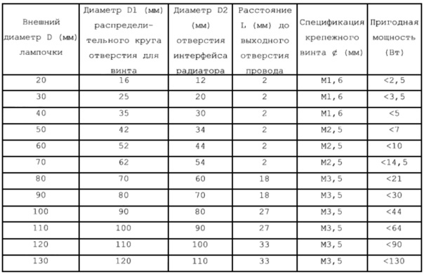
Примечание 1: внешний диаметр D3 радиатора лампочки или внешняя крышка составляют не больше, чем D2-1;Note 1: the outer diameter D3 of the bulb radiator or the outer cover is no more than D2-1;
Примечание 2: диаметр Ф выходного отверстия провода лампочки определяется согласно размеру соединителя лампочки (интерфейса).Note 2: the diameter Φ of the outlet of the bulb wire is determined according to the size of the bulb connector (interface).
Вариант выполнения 1-1Option 1-1
Светодиодная туннельная лампа, работающая в архитектурных конструкциях таких, как туннель, трубопровод, или пещера, использующая конструкцию двустороннего радиатора, включает в себя двусторонний радиатор 103 экструзионного типа, образованный экструзией металла, причем светодиодная лампочка 102 прикреплена к двустороннему радиатору 103 экструзионного типа, двусторонний радиатор 103 экструзионного типа установлен на опоре 104 для установки, и один или более интерфейсов установки, используемых для установки светодиодной лампочки 102, прикреплены к двустороннему радиатору 103 экструзионного типа. Двусторонний радиатор 103 экструзионного типа включает в себя подложку, и на двух сторонах подложки обеспечены ребра; на одной стороне подложки обеспечен интерфейс установки, используемый для установки светодиодной лампочки 102, и круглые или эллиптические конические пространства образованы путем подрезания ребер около интерфейса установки подложки согласно углу освещения света, излучаемого лампочкой, вплоть до того, чтобы не заслонять свет, излучаемый светодиодной лампочкой 102; интерфейс установки включает в себя поверхность в контакте со светодиодной лампочкой 102 и отверстие, соединенное со светодиодной лампочкой, на двустороннем радиаторе 103 экструзионного типа; светодиодная туннельная лампа, использующая конструкцию двустороннего радиатора, дополнительно включает в себя соединитель 106 пучка проводов, и соединитель 106 пучка проводов используется для соединения множества светодиодных лампочек 102 с источником питания и схемой управления. Двусторонний радиатор 103 экструзионного типа установлен на опоре 104 для установки с помощью реверсивной соединительной пластины 110, реверсивная соединительная пластина 110 закреплена на отводном кронштейне 108, а отводной кронштейн 108 закреплен на опоре 104 для установки так, что угол двустороннего радиатора 103 экструзионного типа может одновременно регулироваться в горизонтальном направлении и вертикальным направлении; соединитель 106 пучка проводов прикреплен к опоре 104 для установки. Или двусторонний радиатор 103 экструзионного типа соединен с кронштейном 117 для радиатора; кронштейн 117 для радиатора используется для установки двустороннего радиатора 103 экструзионного типа на опоре 104 для установки с помощью поворотной соединительной пластины 110, кронштейн 117 для радиатора соединен с поворотной соединительной пластиной 110, поворотная соединительная пластина 110 закреплена на отводном кронштейне 108, а отводной кронштейн 108 закреплен на опоре 104 для установки так, что угол двустороннего радиатора 103 экструзионного типа может одновременно регулироваться в горизонтальном направлении и вертикальном направлении; соединитель 106 пучка проводов прикреплен к опоре 117 для установки. Шесть крепежных отверстий фланца на интерфейсе установки двустороннего радиатора 103 экструзионного типа равномерно распределены по диаметру D1, а диаметр D1 представляет собой значение, получаемое путем вычитания диаметра крепежной винтовой гайки и далее вычитания величины 0,8-4 мм из внешнего диаметра D светодиодной лампочки 102.An LED tunnel lamp operating in architectural structures such as a tunnel, pipeline, or cave using a double-sided radiator design includes a double-sided
Вариант выполнения 1-2Option 1-2
Светодиодная туннельная лампа, работающая в архитектурных конструкциях таких, как туннель, трубопровод, или пещера, использующая конструкцию двустороннего радиатора, которая показана на Фиг. 34 и Фиг. 35, включает в себя двусторонний радиатор 103 экструзионного типа, образованный экструзией металла, причем светодиодная лампочка 102 прикреплена к двустороннему радиатору 103 экструзионного типа, двусторонний радиатор 103 экструзионного типа установлен на опоре 104 для установки, и один или более интерфейсов установки, используемых для установки светодиодной лампочки 102, прикреплены к двустороннему радиатору 103 экструзионного типа. Двусторонний радиатор 103 экструзионного типа включает в себя подложку, и на двух сторонах подложки обеспечены ребра; на одной стороне подложки обеспечен интерфейс установки, используемый для установки светодиодной лампочки 102, и круглые или эллиптические конические пространства образованы путем подрезания ребер около интерфейса установки подложки согласно углу освещения света, излучаемого лампочкой, вплоть до того, чтобы не заслонять свет, излучаемый светодиодной лампочкой 102, как показано на Фиг. 36; интерфейс установки включает в себя поверхность в контакте со светодиодной лампочкой 102 и отверстие, соединенное со светодиодной лампочкой, на двустороннем радиаторе 103 экструзионного типа; светодиодная туннельная лампа, использующая конструкцию двустороннего радиатора, дополнительно включает в себя соединитель 106 пучка проводов, и соединитель 106 пучка проводов используется для соединения множества светодиодных лампочек 102 с источником питания и схемой управления. Двусторонний радиатор 103 экструзионного типа установлен на опоре 104 для установки с помощью реверсивной соединительной пластины 110, реверсивная соединительная пластина 110 закреплена на отводном кронштейне 108, а отводной кронштейн 108 закреплен на опоре 104 для установки так, что угол двустороннего радиатора 103 экструзионного типа может одновременно регулироваться в горизонтальном направлении и вертикальном направлении; соединитель 106 пучка проводов прикреплен к опоре 104 для установки. Шесть крепежных отверстий фланца на интерфейсе установки двустороннего радиатора 103 экструзионного типа равномерно распределены по диаметру D1, а диаметр D1 представляет собой значение, получаемое путем вычитания диаметра крепежной винтовой гайки и далее вычитания величины 0,8-4 мм из внешнего диаметра D светодиодной лампочки 102. Светодиодная лампочка 102 установлена на интерфейсе установки с помощью крепежного винта 105 лампочки. Поворотная соединительная пластина 110 соединена с двусторонним радиатором 103 в единое целое с помощью крепежного винта 111 радиатора, поворотная соединительная пластина 110 закреплена на отводном кронштейне 108 с помощью крепежного винта 109 отводного кронштейна, а отводной кронштейн 108 закреплен на опоре 104 для установки с помощью крепежного винта 107 для вращения опоры для установки, как показано на Фиг. 35.An LED tunnel lamp operating in architectural structures such as a tunnel, pipeline, or cave using the double-sided radiator design shown in FIG. 34 and FIG. 35 includes a double-sided
В варианте выполнения или двусторонний радиатор 103 экструзионного типа может быть соединен с кронштейном 117 для радиатора, и кронштейн 117 для радиатора используется для неподвижной установки двустороннего радиатора 103; двусторонний радиатор 103 экструзионного типа также может быть соединен с кронштейном 117 для радиатора, кронштейн 117 для радиатора соединен с поворотной соединительной пластиной 110, поворотная соединительная пластина 110 закреплена на отводном кронштейне 108, а отводной кронштейн 108 закреплен на опоре 104 для установки, а двусторонний радиатор 103 неподвижно установлен с помощью опоры 104 для установки.In an embodiment, either an extrusion-type double-
При использовании настоящее изобретение может быть использовано вертикально или путем крепления вверх к потолку.In use, the present invention can be used vertically or by mounting upward to the ceiling.
В случае повреждения туннельной лампы лампочка может быть удобно обслужена и заменена только путем непосредственного отделения лампочки 102 от двустороннего радиатора 103 экструзионного типа.In case of damage to the tunnel lamp, the bulb can be conveniently maintained and replaced only by directly separating the
В туннельной лампе в настоящем изобретении поворотная запирающая выемка 115 опоры для установки вырезана на опоре 104 для установки, после регулировки угла освещения лампы могут быть привинчены крепежный винт 107 для вращения опоры для установки (винт используется для запирания лампы в направлении силы тяжести для предотвращения ослабления) и крепежный винт 109 отводного кронштейна, поворотный запирающий винт 114 опоры для установки ввинчен в поворотную запирающую выемку 115 опоры для установки для предотвращения изменения направления освещения, как показано на Фиг. 2. В отличие от условия, когда вес самой традиционной туннельной лампы слишком большой, чтобы быть гибкой, одно свойство туннельной лампы в настоящем изобретении заключается в том, что угол освещения может одновременно регулироваться в горизонтальном и вертикальном направлениях путем регулирования крепежного винта 109 отводного кронштейна и крепежного винта 107 для вращения опоры для установки; направление освещения может регулироваться только подобно проблесковому свету в направлении движения, чтобы позволять водителю не видеть источник света так, чтобы эффективно уменьшать проблему ослепления туннельным освещением для обеспечения более хорошей безопасности при вождении транспортного средства.In the tunnel lamp of the present invention, the pivoting locking recess of the mounting
Значения ссылочных позиций в варианте выполнения являются следующими: 102 - светодиодная лампочка, 103 - двусторонний радиатор экструзионного типа, 104 - опора для установки, 105 - крепежный винт лампочки, 106 - соединитель пучка проводов, 107 - крепежный винт для вращения опоры для установки, 108 - отводной кронштейн, 109 - крепежный винт отводного кронштейна, 110 - реверсивная соединительная пластина, 111 - крепежный винт радиатора, 114 - реверсивный запирающий винт опоры для установки, 115 - поворотная запирающая выемка опоры для установки, 117 - кронштейн для радиатора и 118 - реверсивный крепежный винт.The values of the reference positions in the embodiment are as follows: 102 — LED bulb, 103 — two-sided extrusion-type radiator, 104 — support for the installation, 105 — fastening screw of the bulb, 106 — connector of the wire bundle, 107 — fastening screw for rotating the support for installation, 108 - outlet bracket, 109 - fixing screw of the outlet bracket, 110 - reversing connecting plate, 111 - fixing screw of the radiator, 114 - reversing locking screw of the mounting support, 115 - turning locking recess of the mounting support, 117 - bracket for rad Ator and 118 - reversing screw.
Вариант выполнения 2
Светодиодная уличная лампа, использующая конструкцию радиатора экструзионного типа, которая показана на Фиг. 1, Фиг. 2 и Фиг. 3, включает в себя радиатор 103 экструзионного типа, образованный экструзией металла, причем интерфейс установки прикреплен к радиатору 103 экструзионного типа, и светодиодная лампочка 102 прикреплена к интерфейсу установки; радиатор 103 экструзионного типа установлен на подставке 108 для лампы; снаружи радиатора 103 экструзионного типа обеспечен колпак 101, образованный выдавливанием из металла или отлитый под давлением из пластмассы; светодиодная уличная лампа, использующая конструкцию радиатора экструзионного типа, дополнительно включает в себя соединитель 106 пучка проводов, и соединитель 106 пучка проводов используется для соединения множества светодиодных лампочек 102 с источником питания и схемой управления. Радиатор 103 экструзионного типа включает в себя подложку, на одной стороне подложки обеспечены ребра, которые показаны на Фиг. 2, и отверстие для кабеля прикреплено к подложке; на другой стороне подложки обеспечен интерфейс установки, используемый для установки светодиодной лампочки 102; кронштейн 112 для проводящего провода обеспечен на стороне с ребрами подложки, и кронштейн 112 для проводящего провода используется для соединения проводящего провода, выходящего из светодиодной лампочки 102, с соединителем 106 пучка проводов; интерфейс установки включает в себя поверхность в контакте со светодиодной лампочкой 102 и отверстие, соединенное со светодиодной лампочкой, на радиаторе 103 экструзионного типа. Одна сторона подложки радиатора 103 экструзионного типа соединена с L-образной соединительной пластиной 110, a L-образная соединительная пластина 110 соединена с подставкой 108 для лампы; соединитель 106 пучка проводов прикреплен к радиатору 103 экструзионного типа. Шесть крепежных отверстий фланца, прикрепленные к интерфейсу установки, равномерно распределены по диаметру D1, а диаметр D1 представляет собой значение, получаемое путем вычитания диаметра крепежной винтовой гайки и далее вычитания величины 0,8-4 мм из внешнего диаметра D светодиодной лампочки 102. Светодиодная лампочка 102 установлена на радиаторе 103 экструзионного типа с помощью крепежного винта 105 лампочки, колпак 101 обеспечен к радиатору 103 экструзионного типа с помощью группы 104 крепежного винта корпуса лампы, а соединитель 106 пучка проводов прикреплен к радиатору 103 экструзионного типа с помощью кронштейна и винта 107 соединителя пучка проводов. Радиатор 103 экструзионного типа установлен на подставке 108 для лампы с помощью L-образной соединительной пластины 110, крепежного болта 109 для установки уличной лампы и крепежного винта 111 радиатора.An LED street lamp using an extrusion-type radiator design as shown in FIG. 1, FIG. 2 and FIG. 3 includes an
В варианте выполнения отверстие для установки кронштейна прикреплено к подложке или центру радиатора 103 экструзионного типа, и радиатор 103 экструзионного типа установлен на подставке 108 для лампы посредством отверстия для установки кронштейна и крепежного кольца 116 подставки для лампы, радиатор 103 экструзионного типа закреплен на подставке 108 для лампы с помощью крепежного болта 109 для установки уличной лампы, а в подставке 108 для лампы обеспечен соединитель 106 пучка проводов. При этом отсутствует необходимость использования соединителя пучка проводов и винта 107.In an embodiment, the bracket mounting hole is attached to the substrate or center of the
В настоящем изобретении также может быть принят бочкообразный колпак 101, который показан на Фиг. 42, Фиг. 44 и Фиг. 45.A barrel-shaped
В настоящем изобретении во время обслуживания, как показано на Фиг. 1, Фиг. 24 и Фиг. 28, лампочка может быть удобно отделена и установлена только путем отделения колпака 101 так, что лампочку очень удобно обслуживать и заменять.In the present invention, during servicing, as shown in FIG. 1, FIG. 24 and FIG. 28, the bulb can be conveniently separated and installed only by separating the
Значения ссылочных позиций в варианте выполнения являются следующими: 101 - колпак, 102 - светодиодная лампочка, 103 - радиатор экструзионного типа, 104 - группа крепежного винта колпака, 105 - крепежный винт лампочки, 106 - соединитель пучка проводов, 107 - кронштейн и винт соединителя пучка проводов, 108 - подставка для лампы, 109 - крепежный болт для установки уличной лампы, 110 - L-образная соединительная пластина, 111 - крепежный винт радиатора, 112 - кронштейн для проводящего провода, 116 - крепежное кольцо подставки для лампы, 301 - крепежное отверстие установочного фланца лампочки, 302 - отверстие заклепки покрытия кронштейна, 501 - выступ заклепки покрытия кронштейна и 502 - отверстие кромки источника питания или управляющего конца.The values of the reference positions in the embodiment are as follows: 101 - cap, 102 - LED bulb, 103 - extrusion type radiator, 104 - cap fixing screw group, 105 - bulb fixing screw, 106 - wire bundle connector, 107 - beam and beam connector screw wires, 108 - stand for the lamp, 109 - mounting bolt for installing a street lamp, 110 - L-shaped connecting plate, 111 - mounting screw for the radiator, 112 - bracket for the conductive wire, 116 - mounting ring of the stand for the lamp, 301 - mounting hole installation about the bulb flange, 302 - the rivet of the bracket cover, 501 - the protrusion of the rivet of the bracket and 502 - the hole of the edge of the power source or control end.
Вариант выполнения 3
Светодиодная проекционная лампа, использующая колпак в качестве конструкции кронштейна интерфейса установки, которая показана на Фиг. 46, Фиг. 47 и Фиг. 48, включает в себя колпак 101, образованный выдавливанием из листового металла с помощью процесса штампования, причем интерфейс установки прикреплен к колпаку 101, светодиодная лампочка 102, обеспеченная радиатором, обеспечена к интерфейсу установки, средняя часть корпуса 101 лампы соединена с крепежной муфтой 108 подставки для лампы с помощью крепежного элемента подставки для лампы, и декоративная крышка 114 прикреплена к колпаку 101. Колпак 101 является круглым, группа круглых кольцеобразных интерфейсов установки обеспечена в окружении крепежной муфты 108 подставки для лампы в верхней части центра колпака 101, а для усиления конструктивной прочности на краю колпака 101 обеспечен краевой отгиб; декоративная крышка 114 обеспечена в центре нижней части колпака 101; интерфейс установки включает в себя поверхность в контакте со светодиодной лампочкой 102 и отверстие, соединенное со светодиодной лампочкой, на колпаке 101; соединитель 106 пучка проводов обеспечен к крепежной муфте 108 подставки для лампы, и соединитель 106 пучка проводов используется для соединения множества светодиодных лампочек 102 с источником питания и схемой управления. Крепежный элемент подставки для лампы включает в себя фланец 112 крепежной муфты, болт 111 крепежной муфты подставки для лампы и усиливающую пластину 113; крепежная муфта 108 подставки для лампы неподвижно соединена с колпаком 101 с помощью фланца 112 крепежной муфты, болта 111 крепежной муфты подставки для лампы и усиливающей пластины 113. Шесть крепежных отверстий фланца и отверстие интерфейса радиатора прикреплены к интерфейсу установки, крепежные отверстия фланца используются для крепления светодиодной лампочки 102, а отверстие интерфейса радиатора используется для обеспечения прохода радиатора светодиодной лампочки 102 через интерфейс установки лампочки; крепежные отверстия фланца равномерно распределены по диаметру D1, а диаметр D1 представляет собой значение, получаемое путем вычитания диаметра крепежной винтовой гайки и далее вычитания величины 0,8-4 мм из внешнего диаметра D светодиодной лампочки 102; диаметр D2 отверстия интерфейса радиатора на интерфейсе установки представляет собой значение, получаемое путем двукратного вычитания диаметра крепежной винтовой гайки и далее двукратного вычитания величины, соответствующей диаметру D1, из внешнего диаметра лампочки. Соединитель 106 пучка проводов закреплен на крепежной муфте 108 подставки для лампы с помощью кронштейна и винта 107 соединителя пучка проводов, крепежная муфта 108 подставки для лампы закреплена на колпаке 101 с помощью фланца 112 крепежной муфты, усиливающей пластины 110 и винта 111 фланца крепежной муфты, внешняя подставка для лампы соединена с крепежной муфтой 108 подставки для лампы с помощью крепежного винта 109 подставки для лампы, а светодиодная лампочка 102 установлена на отверстии интерфейса установки с помощью крепежного винта 105 лампочки.An LED projection lamp using a cap as a structure of an installation interface bracket, which is shown in FIG. 46, FIG. 47 and FIG. 48 includes a
Значения ссылочных позиций сопровождающих чертежей в варианте выполнения являются следующими: 101 - колпак, 102 - светодиодная лампочка, 103 - радиатор, 105 - крепежный винт лампочки, 106 - соединитель пучка проводов, 107 - кронштейн и винт соединителя пучка проводов, 108 - крепежная муфта подставки для лампы, 109 - крепежный винт подставки для лампы, 111 - болт крепежной муфты подставки для лампы, 112 - фланец крепежной муфты, 113 - усиливающая пластина и 114 - декоративная крышка.The values of the reference positions of the accompanying drawings in the embodiment are as follows: 101 - cap, 102 - LED bulb, 103 - radiator, 105 - mounting screw of the bulb, 106 - connector of the wire bundle, 107 - bracket and screw of the connector of the wire bundle, 108 - mounting bracket of the stand for a lamp, 109 - a fixing screw for a lamp stand, 111 - a bolt of a fixing sleeve for a lamp stand, 112 - a flange of a fixing sleeve, 113 - a reinforcing plate and 114 - a decorative cover.
Вариант выполнения 4
Светодиодная проекционная лампа, использующая колпак в качестве конструкции кронштейна интерфейса установки, которая показана на Фиг. 49, Фиг. 50 и Фиг. 51, включает в себя колпак 101 и светодиодную лампочку 102, причем кронштейн 101 корпуса лампы представляет собой прямоугольный блок с открытой поверхностью, двусторонний радиатор 103 экструзионного типа обеспечен в колпаке 101, отверстие, используемое для установки двустороннего радиатора 103 экструзионного типа, прикреплено к поверхности, противоположной отверстию колпака 101, вентиляционные отверстия прикреплены к поверхностям, отличным от открытой поверхности и поверхности, обеспеченной отверстием колпака 101, а колпак 101 установлен и закреплен с помощью крепежных узлов, обеспеченных на двух сторонах; интерфейс установки, используемый для установки светодиодной лампочки 102, прикреплен к двустороннему радиатору 103 экструзионного типа. Каждый крепежный узел включает в себя крепежный кронштейн 108 лампы и усиливающую пластину 114, усиливающая пластина 114 неподвижно обеспечена в колпаке 101, а крепежный кронштейн 108 лампы соединен с усиливающей пластиной 114 снаружи колпака 101 для крепления всего колпака 101; светодиодная проекционная лампа, использующая радиатор экструзионного типа, дополнительно включает в себя соединитель 106 пучка проводов, и соединитель 106 пучка проводов используется для соединения множества светодиодных лампочек 102 с источником питания и схемой управления. Светодиодная проекционная лампа, использующая двусторонний радиатор экструзионного типа, дополнительно включает в себя узел 112 регулировки угла и заднюю крышку 113 колпака, узел 112 регулировки угла обеспечен в соединении крепежного кронштейна 108 лампы и усиливающей пластины 114, задняя крышка 113 колпака обеспечена в отверстии колпака 101, а вентиляционное отверстие обеспечено к задней крышке колпака. Двусторонний радиатор 103 экструзионного типа включает в себя подложку, и на двух сторонах подложки обеспечены ребра, как показано на Фиг. 52; на одной стороне подложки обеспечен интерфейс установки, используемый для установки светодиодной лампочки 102, и круглые или эллиптические конические пространства образованы путем подрезания ребер около интерфейса установки подложки согласно углу освещения света, излучаемого лампочкой, вплоть до того, чтобы не заслонять свет, излучаемый светодиодной лампочкой 102; интерфейс установки включает в себя поверхность в контакте со светодиодной лампочкой 102 и отверстие, соединенное со светодиодной лампочкой, на двустороннем радиаторе 103 экструзионного типа. Шесть крепежных отверстий фланца на интерфейсе установки двустороннего радиатора 103 экструзионного типа равномерно распределены по диаметру D1, а диаметр D1 представляет собой значение, получаемое путем вычитания диаметра крепежной винтовой гайки и далее вычитания величины 0,8-4 мм из внешнего диаметра D светодиодной лампочки 102. Двусторонний радиатор 103 экструзионного типа установлен в колпаке 101 с помощью крепежного винта 104 радиатора. Светодиодная лампочка 102 закреплена на интерфейсе установки двустороннего радиатора 103 экструзионного типа с помощью крепежного винта 105 лампочки, а крепежный кронштейн 108 лампы закреплен на колпаке 101 с помощью усиливающей пластины 114 и крепежного болта 109.An LED projection lamp using a cap as a structure of an installation interface bracket, which is shown in FIG. 49, FIG. 50 and FIG. 51 includes a
В варианте выполнения также могут быть приняты плотно расположенные светодиодные лампочки (9 светодиодных лампочек обеспечены внутри колпака 101), как показано на Фиг. 53 и Фиг. 54.In an embodiment, tightly spaced LED bulbs can also be adopted (9 LED bulbs are provided inside cap 101), as shown in FIG. 53 and FIG. 54.
В настоящем изобретении в случае повреждения, как показано на Фиг. 49, лампочка может быть удобно обслужена и заменена только путем отделения светодиодной лампочки 102 от двустороннего радиатора 103 экструзионного типа.In the present invention, in the event of damage, as shown in FIG. 49, the bulb can be conveniently maintained and replaced only by separating the
Значения ссылочных позиций в варианте выполнения являются следующими: 101 - колпак, 102 - светодиодная лампочка, 103 - двусторонний радиатор экструзионного типа, 104 - крепежный винт радиатора, 105 - крепежный винт лампочки, 106 - соединитель пучка проводов, 108 - крепежный кронштейн лампы, 109 - крепежный винт, 112 - узел регулировки угла, 113 - задняя крышка колпака и 114 - усиливающая пластина.The values of the reference positions in the embodiment are as follows: 101 — cap, 102 — LED bulb, 103 — two-sided extrusion-type radiator, 104 — radiator fixing screw, 105 — bulb fixing screw, 106 — wire bundle connector, 108 — lamp mounting bracket, 109 - a fixing screw, 112 - an angle adjustment unit, 113 - a back cover of a cap and 114 - a reinforcing plate.
Вариант выполнения 5Option 5
Светодиодная садовая лампа, использующая объединенный элемент кронштейна интерфейса установки, который показан на Фиг. 1, Фиг. 25 и Фиг. 26, включает в себя объединенный элемент кронштейна интерфейса установки, причем светодиодная лампочка 102 с водонепроницаемыми и пыленепроницаемыми функциями и обеспеченная радиатором прикреплена к объединенному элементу кронштейна интерфейса установки; узел колпака, образованный выдавливанием из металла или отлитый под давлением из пластмассы, обеспечен снаружи объединенного элемента кронштейна интерфейса установки; объединенный элемент кронштейна интерфейса установки включает в себя кронштейн 108 трубы, который образован разделением на части стандартной трубы, крепежный фланец 106 лампы и крепежный кронштейн 110 колпака и лампочки, кронштейн 108 трубы, крепежный фланец 106 лампы и крепежный кронштейн 110 колпака и лампочки соединены, интерфейс установки, используемый для установки светодиодной лампочки 102, прикреплен к крепежному кронштейну 110 колпака и лампочки, а кронштейн 108 трубы соединен с крепежным фланцем 106 лампы и крепежным кронштейном 110 колпака и лампочки; узел колпака соединен с объединенным элементом кронштейна интерфейса установки с помощью крепежного кронштейна 110 колпака и лампочки. Интерфейс установки включает в себя поверхность в контакте со светодиодной лампочкой 102 и отверстие, соединенное со светодиодной лампочкой, на крепежном кронштейне 110 колпака и лампочки; светодиодная лампочка 102 установлена на крепежном кронштейне 110 колпака и лампочки с помощью крепежного винта 105 лампочки; крепежный кронштейн 110 колпака и лампочки образован выдавливанием из металла, центральный участок крепежного кронштейна 110 колпака и лампочки соединен с кронштейном 108 трубы, крепежный кронштейн 110 колпака и лампочки огибает его участок, соединенный с кронштейном 108 трубы, так, что проход кабеля и образование эффекта тяги в колпаке облегчают обеспечение эффектов вентиляции и излучения; отверстие для винта, используемое для установки узла колпака, обеспечено на краю крепежного кронштейна 110 колпака и лампочки, и узел колпака прикреплен к крепежному кронштейну 110 колпака и лампочки с помощью крепежного винта 104 колпака. Узел колпака включает в себя колпак 101, вентиляционную крышку 111, светоизлучающую крышку 114 и защитную крышку 115, которые взаимно используются, колпак 101 накрывает снаружи крепежный кронштейна 110 колпака или лампочки, вентиляционная крышка 111 накрывает снаружи кронштейн 108 трубы, защитная крышка 115 установлена в верхней части светодиодной лампочки 102 и между колпаком 101 и вентиляционной крышкой 111 для того, чтобы предотвращать излучение света в вентиляционную крышку 111 и уменьшать попадание комаров в вентиляционную крышку 111, а светоизлучающая крышка 114 обеспечена в верхней части колпака 101.An LED garden lamp using an integrated installation interface bracket element as shown in FIG. 1, FIG. 25 and FIG. 26 includes an integrated element of an installation interface bracket, wherein the
В варианте выполнения узел колпака может дополнительно включать колпак 101, вентиляционную крышку 111, крышку 112 с удлинением, сальник 113 светоизлучающей крышки и защитную крышку 115, которые взаимно используются, колпак 101 накрывает снаружи крепежный кронштейн 110 колпака или лампочки, вентиляционная крышка накрывает снаружи кронштейн 108 трубы, защитная крышка 115 установлена в верхней части светодиодной лампочки 102 и между колпаком 101 и вентиляционной крышкой 111 для того, чтобы предотвращать излучение света в вентиляционную крышку 111 и предотвращать попадание комаров в воздухонепроницаемый колпак 101, крышка 112 с удлинением обеспечена в нижней части вентиляционной крышки 111, а сальник 113 светоизлучающей крышки обеспечен в верхней части колпака 101, как показано на Фиг. 2, Фиг. 27 и Фиг. 28.In an embodiment, the cap assembly may further include a
Или узел колпака может дополнительно включать колпак 101, вентиляционную крышку 111, крышку 112 с удлинением, сальник 113 светоизлучающей крышки, светоизлучающую крышку 114 и защитную крышку 115, которые совместно используются, колпак 101 накрывает снаружи крепежный кронштейн 110 колпака или лампочку, вентиляционная крышка 111 накрывает снаружи кронштейн 108 трубы, крышка 112 с удлинением обеспечена в нижней части вентиляционной крышки 111, защитная крышка 115 установлена в верхней части светодиодной лампочки 102 и между колпаком 101 и вентиляционной крышкой 111 для того, чтобы предотвращать излучение света в вентиляционную крышку 111 и предотвращать попадание комаров в воздухонепроницаемый колпак 101, светоизлучающая крышка 114 обеспечена в колпаке 101 и в верхней части защитной крышки 115 для запирания светодиодной лампочки 102, а верхняя часть светоизлучающей крышки закреплена сальником 113 светоизлучающей крышки, обеспеченным в верхней части колпака 101, как показано на Фиг. 24, Фиг. 29 и Фиг. 30.Or, the cap assembly may further include a
При использовании выбираются различные узлы колпака согласно различным требованиям.In use, various hood assemblies are selected according to different requirements.
При использовании настоящего изобретения согласно различным требованиям выбираются различные крепежные фланцы 106 лампы для адаптации к различным случаям установки. При установке на конструкции кронштейна трубы они являются такими, которые показаны на Фиг. 27. Для того, чтобы лучше предотвращать пыль, при использовании настоящего изобретения крепежное отверстие 301 установочного фланца лампочки на теплопроводящем кронштейне 3 может быть исключено, и ее внешний диаметр уменьшен, чтобы быть равным внешнему диаметру стопорного кольца 8 линзы, как показано на Фиг. 23.When using the present invention, according to different requirements, various
Значения ссылочных позиций в варианте выполнения являются следующими: 101 - колпак, 102 - светодиодная лампочка, 103 - радиатор, 104 - крепежный винт радиатора, 105 - крепежный винт лампочки, 106 - крепежный фланец лампы, 108 - кронштейн трубы, 110 - крепежный кронштейн колпака или лампочки, 111 - вентиляционная крышка, 112 - крышка с удлинением, 113 - сальник светоизлучающей крышки, 114 - светоизлучающая крышка, 115 - защитная крышка, 301 - крепежное отверстие установочного фланца лампочки, 302 - отверстие заклепки покрытия кронштейна, 501 - выступ заклепки покрытия кронштейна и 502 - отверстие кромки источника питания или управляющего конца.The values of the reference positions in the embodiment are as follows: 101 — cap, 102 — LED bulb, 103 — radiator, 104 — fixing screw of the radiator, 105 — fixing screw of the bulb, 106 — fixing flange of the lamp, 108 — pipe bracket, 110 — fixing bracket of the cap or bulbs, 111 - ventilation cover, 112 - cover with extension, 113 - light-emitting cover gasket, 114 - light-emitting cover, 115 - protective cover, 301 - mounting hole of the lamp mounting flange, 302 - bracket rivet hole, 501 - coating rivet protrusion bracket on and 502 - the hole of the edge of the power source or control end.
Вариант выполнения 6
Светодиодная ввинчиваемая лампа, которая показана на Фиг. 64, включает в себя цоколь 108 ввинчиваемой лампы, радиатор 103, светодиодную лампочку 102 и колпак 101; промежуточный соединительный элемент 110 на цоколе 108 ввинчиваемой лампы соединен с радиатором 103 с помощью резьб на нем или с помощью крепежного винта 111 цоколя лампы или путем непосредственного склеивания; светодиодная лампочка 102 неподвижно установлена с помощью крепежного винта 105 лампочки с радиатором 103 или теплопроводящей преобразовательной пластиной 27 (теплопроводящая преобразовательная пластина 27 закреплена в отверстии 104А для крепежного винта на радиаторе 103 с помощью крепежного винта 104 для совместной установки) в качестве интерфейса AZM установки, а колпак 101 соединен с радиатором 103 или теплопроводящей преобразовательной пластиной 27 путем склеивания или резьбового соединения или зажима. Интерфейс установки включает в себя поверхность в контакте со светодиодной лампочкой 102 и отверстие, соединенное со светодиодной лампочкой, на радиаторе 103 или теплопроводящей преобразовательной пластине 27. Радиатор 103 является цилиндрическим, который показан на Фиг. 65 и Фиг. 66, радиатор обеспечен толщиной подложки радиатора внутрь на максимальном внешнем диаметре цилиндра и обеспечен ребрами по направлению к центру цилиндра по радиальной линии, 2-3 слоя прерывистых выемок прикреплены к радиатору вдоль уплотненной круглой дуги с подложкой в качестве толщины, после нагрева радиатора наружный воздух самопроизвольно течет в центр радиатора через прерывистые выемки для образования конвекции так, чтобы достигать эффекта охлаждения. Радиатор 103 также может представлять собой конвекционный радиатор, который показан на Фиг. 67, Фиг. 68 и Фиг. 69, радиатор обеспечен толщиной подложки радиатора наружу от цилиндрической поверхности (при использовании внешнего диаметра фланца прямо закрепленной розетки соединителя в качестве диаметра) в центре и обеспечен ребрами наружу от подложки путем излучения по радиальной линии, и на поверхности каждого ребра вверх образована дуга для постепенного увеличения открытой площади; поверхность каждого ребра накрыта колпаком, и между внешней крышкой и ребрами образовано множество сквозных каналов потока воздуха; после нагрева радиатора воздух поступает из отверстия канала потока в более низком конце и вытекает из отверстия канала потока в более высоком конце радиатора для образования эффекта тяги для того, чтобы достигать конвекции воздуха для рассеивания тепла. Радиатор ввинчиваемой лампы также может принимать любую форму при условии обеспечения закрепленной розетки соединителя и интерфейса установки. Например, радиатор в форме подсолнуха изготавливается в различных формах для получения различных схем ввинчиваемой лампы, которые показаны на Фиг. 70 и Фиг. 71. Для светодиодного решения, в котором для возбуждения принят традиционный источник питания, источник 106 возбуждения питания может быть обеспечен в центральном положении между радиатором 103 ввинчиваемой лампы и цоколем 108 лампы, как показано на Фиг. 72. Колпак 101 лампочки может принимать различные формы для получения различных эффектов внешнего вида, например, грибовидной головки, свечеобразной головки, круглой головки и плоской головки. Розетка 10 соединителя прикреплена к радиатору 103 или теплопроводящей преобразовательной пластине 27, розетка 10 соединителя взаимно соединена со штепселем 11 соединителя на светодиодной лампочке, фланец с тремя отверстиями обеспечен к розетке 10 соединителя, розетка соединителя прикреплена к радиатору 103 или теплопроводящей преобразовательной пластине 27 с помощью фланца с тремя отверстиями и крепежного винта 25 розетки соединителя, и между фланцем и радиатором 103 или теплопроводящей преобразовательной пластиной 27 дополнительно обеспечена закрепленная регулировочная резиновая прокладка 24 для обеспечения герметичности водонепроницаемой поверхности; проводящий провод, выходящий из розетки соединителя, припаян к цоколю 108 лампы. Светодиодная лампочка 102 выполнена следующим путем: модуль оптического источника приклеен в центре теплопроводящего кронштейна, обеспеченного установочным фланцем; или неметаллический теплопроводящий кронштейн, обеспеченный фланцем, изготовлен за одно целое с модулем оптического источника из одинакового материала; конструкция между модулем оптического источника и теплопроводящим кронштейном является простой и гладкой, являясь подходящей для рассеивания тепла СИД, а светодиодная лампочка установлена на интерфейсе установки с помощью фланца.The LED screw lamp, which is shown in FIG. 64 includes a
Значения ссылочных позиций в варианте выполнения являются следующими: 101 - колпак, 102 - светодиодная лампочка в настоящем изобретении, 103 - радиатор, 104 - крепежный винт, 104А - отверстие для крепежного винта, 105 - крепежный винт лампочки, 106 - источник возбуждения питания, 108 - цоколь ввинчиваемой лампы, 109 - колпак, 110 - промежуточный соединительный элемент, 301 - крепежное отверстие фланца и AZM - интерфейс установки.The values of the reference positions in the embodiment are as follows: 101 - cap, 102 - LED bulb in the present invention, 103 - radiator, 104 - mounting screw, 104A - hole for the mounting screw, 105 - mounting screw of the bulb, 106 - power supply source, 108 - screw lamp base, 109 - cap, 110 - intermediate connecting element, 301 - mounting hole of the flange and AZM - installation interface.
Вариант выполнения 7
Светодиодная цилиндрическая лампа, использующая кронштейн основания в качестве интерфейса установки, которая показана на Фиг. 74, Фиг. 75 и Фиг. 76, включает в себя цилиндрическую лампу, причем цилиндрическая лампа включает в себя кронштейн 108 основания и пружинные крепежные зажимы 107, кронштейн 108 основания является кольцеобразным, а пружинные крепежные зажимы 107 обеспечены на двух сторонах кронштейна 108 основания; цилиндрическая лампа обеспечена интерфейсом AZM установки на кронштейне 108 основания для неподвижной установки светодиодной лампочки 102. Интерфейс AZM установки включает в себя поверхность в контакте со светодиодной лампочкой 102 и отверстие, соединенное со светодиодной лампочкой, на кронштейне 108 основания. Интерфейс AZM установки на кронштейне 108 основания включает в себя отверстие интерфейса радиатора и шесть крепежных отверстий фланца, крепежные отверстия фланца используются для крепления светодиодной лампочки 102, а отверстие интерфейса радиатора используется для обеспечения прохода светодиодной лампочки 102 через интерфейс установки; крепежные отверстия фланца равномерно распределены по диаметру D1, а диаметр D1 представляет собой значение, получаемое путем вычитания диаметра крепежной винтовой гайки и далее вычитания величины 0,8-4 мм из внешнего диаметра D светодиодной лампочки 102; диаметр D2 отверстия интерфейса радиатора на интерфейсе установки представляет собой значение, получаемое путем двукратного вычитания диаметра крепежной винтовой гайки и далее двукратного вычитания величины, соответствующей диаметру D1, из внешнего диаметра D лампочки. Светодиодная лампочка 102 установлена на интерфейсе AZM установки с помощью крепежного винта 105 лампочки.An LED cylindrical lamp using the base bracket as the installation interface, which is shown in FIG. 74, FIG. 75 and FIG. 76 includes a cylindrical lamp, the cylindrical lamp including a
В варианте выполнения радиатор светодиодной лампочки с водонепроницаемыми и пыленепроницаемыми функциями и обеспеченной радиатором также может представлять собой радиатор с более большим объемом, как показано на Фиг. 77 и Фиг. 78.In an embodiment, the radiator of an LED bulb with waterproof and dustproof functions and provided with a radiator may also be a radiator with a larger volume, as shown in FIG. 77 and FIG. 78.
В варианте выполнения основание 108 цилиндрической лампы также может иметь форму крышки, как показано на Фиг. 79.In an embodiment, the
В варианте выполнения, когда светодиодная лампочка 102 представляет собой светодиодную лампочку с водонепроницаемыми и пыленепроницаемыми функциями, она является такой, которая показана на Фиг. 80, Фиг. 81 и Фиг. 82.In an embodiment, when the
В варианте выполнения 101 колпак также может быть обеспечен под основанием 108 цилиндрической лампы, опорная крышка 110 колпака обеспечена под 101 колпаком, а 101 колпак закреплен на опорной крышке 110 колпака, как показано на Фиг. 87; опорная крышка 110 колпака зажата на выемке основания 108 цилиндрической лампы с помощью выступа края, который показан на Фиг. 93, Фиг. In an
84, Фиг. 85 и Фиг. 86.84, FIG. 85 and FIG. 86.
Значения ссылочных позиций в варианте выполнения являются следующими: 101 - колпак, 102 - светодиодная лампочка, 103 - радиатор, 105 - крепежный винт лампочки, 107 - пружинный крепежный зажим, 108 - кронштейн интерфейса установки основания и лампочки, 110 - опорная крышка колпака, 301 - крепежное отверстие установочного фланца лампочки, 302 - отверстие заклепки покрытия кронштейна, 501 - выступ заклепки покрытия кронштейна и 502 - отверстие кромки источника питания или управляющего конца.The values of the reference positions in the embodiment are as follows: 101 - cap, 102 - LED bulb, 103 - radiator, 105 - mounting screw of the bulb, 107 - spring mounting clip, 108 - bracket for the base and lamp installation interface, 110 - bearing cap cover, 301 - the mounting hole of the mounting flange of the bulb, 302 - the hole of the rivet cover bracket, 501 - the protrusion of the rivet cover bracket and 502 - the hole of the edge of the power source or the control end.
Вариант выполнения 8
Светодиодная потолочная лампа, которая показана на Фиг. 88, Фиг. 89 и Фиг. 92, включает в себя потолочную лампу, причем потолочная лампа включает в себя основание 106 потолочной лампы и радиатор 103, интерфейс установки лампочки прикреплен к основанию 106 потолочной лампы, а радиатор 103 прикреплен к интерфейсу установки лампочки; интерфейс AZM установки прикреплен в центре нижней части радиатора 103 для неподвижной установки светодиодной лампочки 102. Множество вентиляционных зазоров обеспечено на краю верхней части основания 106 потолочной лампы, радиатор 103 закреплен на основании 106 с помощью крепежного винта 104, после нагрева радиатора 103 во время работы светодиодной потолочной лампы внешний воздух самопроизвольно течет в центр радиатора вдоль вентиляционных зазоров основания 106 для образования конвекции так, чтобы достигать эффекта охлаждения; интерфейс AZM установки включает в себя поверхность в контакте со светодиодной лампочкой 102 и отверстие, соединенное со светодиодной лампочкой, на радиаторе 103. Потолочная лампа дополнительно включает в себя колпак 101, и колпак 101 соединен с основанием 106 потолочной лампы путем зажима или винтового соединения. Вентиляционное отверстие А обеспечено на краю интерфейса установки лампочки основания 106 потолочной лампы и для того, чтобы предотвращать попадание комаров, вентиляционное отверстие А покрыто сеткой 29; Вентиляционное отверстие В прикреплено к колпаку 101 и для того, чтобы предотвращать попадание комаров, вентиляционное отверстие покрыто сеткой 29; внешний воздух может поступать из вентиляционного отверстия В и вытекать из вентиляционного отверстия А для достижения эффекта конвекции и излучения. Потолочная лампа дополнительно включает в себя узел электрического соединителя, узел электрического соединителя включает в себя розетку 10 соединителя, крепежный винт 25 розетки соединителя и закрепленную регулировочную резиновую прокладку 24; розетка 10 соединителя взаимно соединена со штепселем 11 соединителя на светодиодной лампочке 102, фланец с тремя отверстиями прикреплен к розетке 10 соединителя, и розетка соединителя прикреплена к радиатору 103 с помощью фланца с тремя отверстиями и крепежного винта 25 розетки соединителя, а между фланцем и радиатором 103 обеспечена закрепленная регулировочная резиновая прокладка 24 для обеспечения герметичности водонепроницаемой поверхности. Шесть крепежных отверстий фланца на интерфейсе установки радиатора 103 равномерно распределены по диаметру D1, а диаметр D1 представляет собой значение, получаемое путем вычитания диаметра крепежной винтовой гайки и далее вычитания величины 0,8-4 мм из внешнего диаметра D светодиодной лампочки 102. Радиатор 103 представляет собой радиатор в форме подсолнуха, который показан на Фиг. 15. Радиатор 103 установлен на отверстии интерфейса установки лампочки с помощью крепежного винта 104, а светодиодная лампочка 102 установлена на интерфейсе AZM установки с помощью крепежного винта 105 лампочки.The LED ceiling lamp shown in FIG. 88, FIG. 89 and FIG. 92 includes a ceiling lamp, the ceiling lamp including a
В варианте выполнения вентиляционное отверстие А обеспечено на краю отверстия интерфейса установки лампочки основания 106 потолочной лампы, внешний воздух может образовывать конвекцию в продольном направлении радиатора 103 с помощью вентиляционного отверстия для усиления эффекта излучения, вентиляционное отверстие А покрыто сеткой 29 для предотвращения попадания комаров, как показано на Фиг. 90; вентиляционное отверстие В прикреплено к потолочному колпаку 101, и внешний воздух может поступать из вентиляционного отверстия А и вытекать из вентиляционного отверстия В для усиления эффекта излучения; вентиляционное отверстие В покрыто сеткой 29 для предотвращения попадания комаров, как показано на Фиг. 91.In an embodiment, a ventilation hole A is provided at the edge of the opening of the installation interface of the bulb of the base of the
Водонепроницаемый штепсель 10А соединителя с гайкой используется для соединения светодиодной лампочки 102 с источником питания и схемой управления.A
При обслуживании настоящего изобретения открывается только колпак 101 и отделяется крепежный винт 105 для замены светодиодной лампочки 102, таким образом, продлевая срок службы потолочной лампы и уменьшая предполагаемую стоимость вложений в освещение пользователя.When servicing the present invention, only the
Значения ссылочных позиций в варианте выполнения являются следующими: AZM - интерфейс установки лампочки, 101 - колпак, 102 - светодиодная лампочка, 103 - радиатор, 104 - крепежный винт, 105 - крепежный винт лампочки, 106 - основание потолочной лампы и 301 - крепежное отверстие установочного фланца лампочки.The values of the reference positions in the embodiment are as follows: AZM - interface for installing the bulb, 101 - cap, 102 - LED bulb, 103 - radiator, 104 - fixing screw, 105 - fixing screw for the bulb, 106 - base of the ceiling lamp and 301 - mounting hole for the installation bulb flange.
Claims (50)
Applications Claiming Priority (19)
| Application Number | Priority Date | Filing Date | Title |
|---|---|---|---|
| CN201210253682.8 | 2012-07-23 | ||
| CN201210253766.1 | 2012-07-23 | ||
| CN201210253766.1A CN102927463B (en) | 2012-07-23 | 2012-07-23 | LED screw lamp |
| CN201210253483.7 | 2012-07-23 | ||
| CN201210253729.0A CN102818199B (en) | 2012-07-23 | 2012-07-23 | LED (Light-Emitting Diode) ceiling lamp |
| CN201210253730.3 | 2012-07-23 | ||
| CN201210253729.0 | 2012-07-23 | ||
| CN201210253702.1 | 2012-07-23 | ||
| CN201210253481.8A CN102818171B (en) | 2012-07-23 | 2012-07-23 | LED (light-emitting diode) lawn lamp using support composite member as mounting interface |
| CN201210253816.6A CN102777829B (en) | 2012-07-23 | 2012-07-23 | LED project lamp using lamp shell support as mounting interface support structure |
| CN201210253802.4 | 2012-07-23 | ||
| CN201210253702.1A CN102798005B (en) | 2012-07-23 | 2012-07-23 | Construction method for universal-type LED (light-emitting diode) bulb and LED bulb of clamping ring structure |
| CN201210253816.6 | 2012-07-23 | ||
| CN201210253802.4A CN102818180B (en) | 2012-07-23 | 2012-07-23 | LED (Light-Emitting Diode) project lamp utilizing lamp shell as mounting interface bracket structure |
| CN201210253682.8A CN102818175B (en) | 2012-07-23 | 2012-07-23 | LED (light-emitting diode) road lamp adopting extruding radiator structure |
| CN201210253481.8 | 2012-07-23 | ||
| CN201210253730.3A CN102777798B (en) | 2012-07-23 | 2012-07-23 | LED down light taking base bracket as mounting interface |
| CN201210253483.7A CN102777823B (en) | 2012-07-23 | 2012-07-23 | LED tunnel lamp using double-faced radiator structure |
| PCT/CN2013/000880 WO2014015656A1 (en) | 2012-07-23 | 2013-07-23 | Universal-led-bulb construction method, clamping-ring-structured led bulb, and led lamp |
Publications (2)
| Publication Number | Publication Date |
|---|---|
| RU2015105969A RU2015105969A (en) | 2016-09-10 |
| RU2633361C2 true RU2633361C2 (en) | 2017-10-12 |
Family
ID=49996549
Family Applications (1)
| Application Number | Title | Priority Date | Filing Date |
|---|---|---|---|
| RU2015105969A RU2633361C2 (en) | 2012-07-23 | 2013-07-23 | Execution method of universal led bulb, led bulb, having a stopping ring structure, and a led lamp |
Country Status (7)
| Country | Link |
|---|---|
| US (1) | US9709248B2 (en) |
| EP (1) | EP2881647B1 (en) |
| JP (1) | JP6007326B2 (en) |
| KR (1) | KR101778868B1 (en) |
| BR (1) | BR112015001554A2 (en) |
| RU (1) | RU2633361C2 (en) |
| WO (1) | WO2014015656A1 (en) |
Families Citing this family (61)
| Publication number | Priority date | Publication date | Assignee | Title |
|---|---|---|---|---|
| US11435064B1 (en) | 2013-07-05 | 2022-09-06 | DMF, Inc. | Integrated lighting module |
| US11060705B1 (en) | 2013-07-05 | 2021-07-13 | DMF, Inc. | Compact lighting apparatus with AC to DC converter and integrated electrical connector |
| US10139059B2 (en) | 2014-02-18 | 2018-11-27 | DMF, Inc. | Adjustable compact recessed lighting assembly with hangar bars |
| US11255497B2 (en) | 2013-07-05 | 2022-02-22 | DMF, Inc. | Adjustable electrical apparatus with hangar bars for installation in a building |
| US10551044B2 (en) | 2015-11-16 | 2020-02-04 | DMF, Inc. | Recessed lighting assembly |
| US10753558B2 (en) | 2013-07-05 | 2020-08-25 | DMF, Inc. | Lighting apparatus and methods |
| US9964266B2 (en) | 2013-07-05 | 2018-05-08 | DMF, Inc. | Unified driver and light source assembly for recessed lighting |
| US10563850B2 (en) * | 2015-04-22 | 2020-02-18 | DMF, Inc. | Outer casing for a recessed lighting fixture |
| JP6456068B2 (en) * | 2014-07-30 | 2019-01-23 | 三菱電機株式会社 | lighting equipment |
| US9581322B2 (en) * | 2014-09-30 | 2017-02-28 | Aeonovalite Technologies, Inc. | Heat-sink for high bay LED device, high bay LED device and methods of use thereof |
| US20160245468A1 (en) * | 2015-02-20 | 2016-08-25 | Volt, LLC | Deck light with interchangeable housings |
| CA3102022C (en) | 2015-05-29 | 2023-04-25 | DMF, Inc. | Lighting module for recessed lighting systems |
| JP6704174B2 (en) * | 2015-06-29 | 2020-06-03 | パナソニックIpマネジメント株式会社 | Lighting equipment |
| USD851046S1 (en) | 2015-10-05 | 2019-06-11 | DMF, Inc. | Electrical Junction Box |
| US10309588B2 (en) | 2016-08-11 | 2019-06-04 | Abl Ip Holding Llc | Luminaires with transition zones for glare control |
| CN106439642B (en) * | 2016-08-31 | 2019-02-05 | 惠州联合诚创企业管理咨询有限公司 | A kind of pendent lamp installation lamp panel |
| CN106287609A (en) * | 2016-10-20 | 2017-01-04 | 桂林大创科技有限公司 | A kind of LED illumination lamp |
| CN106369349A (en) * | 2016-10-28 | 2017-02-01 | 桂林大创科技有限公司 | LED lamp capable of dissipating heat automatically and driving circuit of LED lamp |
| CN108224105A (en) * | 2017-01-17 | 2018-06-29 | 乐雷光电技术(上海)有限公司 | A kind of low-power LED point light source of waterproof |
| CN106801803B (en) * | 2017-03-28 | 2023-03-14 | 飞策防爆电器股份有限公司 | Encapsulation method and encapsulation structure of explosion-proof LED lamp |
| CN106931327A (en) * | 2017-04-25 | 2017-07-07 | 佛山电器照明股份有限公司 | A kind of PAR lamp |
| CN106969301B (en) * | 2017-05-27 | 2019-07-02 | 中山市乐销照明科技有限公司 | A kind of corner button of ceiling lamp |
| CN107036009A (en) * | 2017-06-12 | 2017-08-11 | 浙江晨丰科技股份有限公司 | A kind of LED projector lamp |
| WO2018237294A2 (en) | 2017-06-22 | 2018-12-27 | DMF, Inc. | Thin profile surface mount lighting apparatus |
| USD905327S1 (en) | 2018-05-17 | 2020-12-15 | DMF, Inc. | Light fixture |
| US10488000B2 (en) | 2017-06-22 | 2019-11-26 | DMF, Inc. | Thin profile surface mount lighting apparatus |
| US11067231B2 (en) | 2017-08-28 | 2021-07-20 | DMF, Inc. | Alternate junction box and arrangement for lighting apparatus |
| WO2019108667A1 (en) | 2017-11-28 | 2019-06-06 | Dmf. Inc. | Adjustable hanger bar assembly |
| CA3087187A1 (en) | 2017-12-27 | 2019-07-04 | DMF, Inc. | Methods and apparatus for adjusting a luminaire |
| CN108131611A (en) * | 2018-02-01 | 2018-06-08 | 中山智途电子科技有限公司 | A kind of warning lamp of water, shock easy to assembly |
| CN108461602B (en) * | 2018-03-16 | 2024-09-20 | 黄璟雯 | Deep ultraviolet LED inorganic packaging base |
| CN108443723A (en) * | 2018-03-26 | 2018-08-24 | 四川能投光电有限公司 | LED light emission device with trim interface and with optical interface |
| USD877957S1 (en) | 2018-05-24 | 2020-03-10 | DMF Inc. | Light fixture |
| WO2019241198A1 (en) | 2018-06-11 | 2019-12-19 | DMF, Inc. | A polymer housing for a recessed lighting system and methods for using same |
| USD903605S1 (en) | 2018-06-12 | 2020-12-01 | DMF, Inc. | Plastic deep electrical junction box |
| CA3115146A1 (en) | 2018-10-02 | 2020-04-09 | Ver Lighting Llc | A bar hanger assembly with mating telescoping bars |
| USD864877S1 (en) | 2019-01-29 | 2019-10-29 | DMF, Inc. | Plastic deep electrical junction box with a lighting module mounting yoke |
| USD1012864S1 (en) | 2019-01-29 | 2024-01-30 | DMF, Inc. | Portion of a plastic deep electrical junction box |
| USD901398S1 (en) | 2019-01-29 | 2020-11-10 | DMF, Inc. | Plastic deep electrical junction box |
| US11168876B2 (en) | 2019-03-06 | 2021-11-09 | Hayward Industries, Inc. | Underwater light having programmable controller and replaceable light-emitting diode (LED) assembly |
| WO2020181249A1 (en) * | 2019-03-06 | 2020-09-10 | Hayward Industries, Inc. | Underwater light having a replaceable light-emitting diode (led) module and cord assembly |
| USD966877S1 (en) | 2019-03-14 | 2022-10-18 | Ver Lighting Llc | Hanger bar for a hanger bar assembly |
| TWI683973B (en) * | 2019-05-22 | 2020-02-01 | 福安工業股份有限公司 | Led vehicle lighting connecting structure |
| CN110195832A (en) * | 2019-06-10 | 2019-09-03 | 深圳星标科技股份有限公司 | Embedded aid-to-navigation light |
| WO2021051101A1 (en) | 2019-09-12 | 2021-03-18 | DMF, Inc. | Miniature lighting module and lighting fixtures using same |
| US11168881B2 (en) * | 2019-11-08 | 2021-11-09 | Nan Ya Photonics Incorporation | LED lamp structure having water tanks, lens member, and support means |
| CN110939896A (en) * | 2019-12-13 | 2020-03-31 | 深圳市中电照明股份有限公司 | Grading lamp shade and LED down lamp of preventing fires |
| CN111629545B (en) * | 2020-06-01 | 2024-06-04 | 深圳市天建通信有限公司 | Heat dissipation fixing device for communication engineering equipment |
| USD990030S1 (en) | 2020-07-17 | 2023-06-20 | DMF, Inc. | Housing for a lighting system |
| CA3124976A1 (en) | 2020-07-17 | 2022-01-17 | DMF, Inc. | Polymer housing for a lighting system and methods for using same |
| US11585517B2 (en) | 2020-07-23 | 2023-02-21 | DMF, Inc. | Lighting module having field-replaceable optics, improved cooling, and tool-less mounting features |
| CN112879877B (en) * | 2021-01-20 | 2022-07-15 | 中铁二局第三工程有限公司 | Supplementary lighting device of prism lens is measured in tunnel |
| EP4043781B1 (en) | 2021-02-10 | 2023-10-11 | Uwe Remus | Wetroom lamp, in particular greenhouse light |
| CN113566148B (en) * | 2021-06-21 | 2023-08-01 | 安徽睿翔光电科技有限公司 | Controllable point light source |
| CN113450670B (en) * | 2021-07-15 | 2023-06-27 | 深圳意科莱照明技术有限公司 | Intelligent transparent granular direct-connected net screen |
| CN113851435B (en) * | 2021-08-06 | 2024-08-13 | 深圳市战狼光电有限公司 | LED module with convenient substrate assembly |
| CN114038978B (en) * | 2021-09-15 | 2023-07-07 | 深圳市华笙光电子有限公司 | Through silicon via LED packaging structure of wafer level glass cavity |
| CN114183716B (en) * | 2021-11-23 | 2023-11-07 | 锐威环球科技(深圳)有限公司 | LED lamp capable of being used in ultralow temperature environment |
| CN114241935B (en) * | 2021-12-22 | 2023-05-02 | 江西瑞晟光电科技有限公司 | Surface mounting LED for outdoor display screen |
| CN114551641B (en) * | 2022-02-10 | 2023-09-12 | 中国科学院上海技术物理研究所 | Thermal layer structure of focal plane detector for physically isolating coupling stress |
| CN114719224A (en) * | 2022-03-14 | 2022-07-08 | 浙江宝铭光学材料有限公司 | Lampshade of LED ceiling lamp |
Citations (9)
| Publication number | Priority date | Publication date | Assignee | Title |
|---|---|---|---|---|
| RU2233013C2 (en) * | 2002-03-06 | 2004-07-20 | Институт проблем химической физики РАН | Semiconductor electroluminescent light source and its manufacturing process (alternatives) |
| CN201110472Y (en) * | 2007-12-04 | 2008-09-03 | 讯凯国际股份有限公司 | LED lamp |
| CN201281266Y (en) * | 2008-10-31 | 2009-07-29 | 包建敏 | High power LED road lighting lamp |
| EP2302295A1 (en) * | 2009-09-24 | 2011-03-30 | Zumtobel Lighting GmbH | Assembly for emitting light with light source and optical element |
| FR2954458A1 (en) * | 2009-12-21 | 2011-06-24 | Fd Dev | Port-hole type lamp for use at e.g. ceiling of corridor, has base provided with basin, where basin crossed by light emitted by light source is opalescent in part of non surface occupied by transparent surface constituting translucent zone |
| CN102213370A (en) * | 2010-04-06 | 2011-10-12 | 亿光电子工业股份有限公司 | Light emitting diode lamp |
| EA201100895A1 (en) * | 2009-12-03 | 2012-01-30 | Общество с ограниченной ответственностью "ДиС ПЛЮС" | A METHOD OF MANUFACTURING A LED LAMP, A LED LAMP MANUFACTURED BY THIS METHOD AND A RADIATOR FOR THIS LAMP |
| US8172434B1 (en) * | 2007-02-23 | 2012-05-08 | DeepSea Power and Light, Inc. | Submersible multi-color LED illumination system |
| TW201221843A (en) * | 2010-11-16 | 2012-06-01 | Zhejiang Manelux Lighting Co Ltd | Lighting module and LED lamp using LED as light source |
Family Cites Families (27)
| Publication number | Priority date | Publication date | Assignee | Title |
|---|---|---|---|---|
| JPH0425774Y2 (en) * | 1988-03-23 | 1992-06-22 | ||
| JPH0461980U (en) * | 1990-10-08 | 1992-05-27 | ||
| JPH09303979A (en) * | 1996-05-09 | 1997-11-28 | Fujikura Ltd | Heat pipe |
| JPH10149861A (en) * | 1996-11-19 | 1998-06-02 | Alps Electric Co Ltd | Fixing structure of connector with terminal |
| JP4735794B2 (en) * | 2003-06-30 | 2011-07-27 | 信越半導体株式会社 | Light emitting module |
| JP2006156187A (en) * | 2004-11-30 | 2006-06-15 | Mitsubishi Electric Corp | Led light source device and led electric bulb |
| JP4760117B2 (en) * | 2005-05-12 | 2011-08-31 | パナソニック電工株式会社 | LIGHT EMITTING DEVICE AND LIGHTING APPARATUS HAVING THE LIGHT EMITTING DEVICE |
| JP2009238734A (en) * | 2008-03-06 | 2009-10-15 | Power Eco Japan Co Ltd | Illumination lamp |
| JP5060357B2 (en) * | 2008-03-25 | 2012-10-31 | スタンレー電気株式会社 | Vehicle headlamp |
| CN201521934U (en) * | 2009-10-26 | 2010-07-07 | 林万炯 | Sealed waterproof LED lamp |
| JP2011096416A (en) * | 2009-10-27 | 2011-05-12 | Panasonic Electric Works Co Ltd | Led lighting fixture |
| US20120206927A1 (en) * | 2009-11-05 | 2012-08-16 | Elm Inc. | Large led lighting apparatus |
| CN201582681U (en) * | 2010-01-20 | 2010-09-15 | 中山市盈点光电科技有限公司 | LED spot lamp |
| JP2011165704A (en) * | 2010-02-04 | 2011-08-25 | Stanley Electric Co Ltd | Heat sink and light emitting element unit |
| JP5459623B2 (en) * | 2010-10-15 | 2014-04-02 | 東芝ライテック株式会社 | Lighting device |
| JP2012133964A (en) * | 2010-12-21 | 2012-07-12 | Panasonic Corp | Led unit, and lighting fixture using the same |
| CN201944619U (en) | 2011-01-21 | 2011-08-24 | 贵阳世纪天元科技有限公司 | Light emitting diode (LED) lamp head with standard interface |
| TWM410983U (en) * | 2011-04-22 | 2011-09-01 | Paragon Sc Lighting Tech Co | Light emitting module |
| CN102818171B (en) | 2012-07-23 | 2015-04-15 | 贵州光浦森光电有限公司 | LED (light-emitting diode) lawn lamp using support composite member as mounting interface |
| CN102777823B (en) * | 2012-07-23 | 2014-10-22 | 贵州光浦森光电有限公司 | LED tunnel lamp using double-faced radiator structure |
| CN102818199B (en) * | 2012-07-23 | 2014-12-10 | 贵州光浦森光电有限公司 | LED (Light-Emitting Diode) ceiling lamp |
| CN102777798B (en) * | 2012-07-23 | 2014-04-02 | 贵州光浦森光电有限公司 | LED down light taking base bracket as mounting interface |
| CN102927463B (en) * | 2012-07-23 | 2014-10-29 | 贵州光浦森光电有限公司 | LED screw lamp |
| CN102818180B (en) * | 2012-07-23 | 2014-10-22 | 贵州光浦森光电有限公司 | LED (Light-Emitting Diode) project lamp utilizing lamp shell as mounting interface bracket structure |
| CN102818175B (en) * | 2012-07-23 | 2014-10-22 | 贵州光浦森光电有限公司 | LED (light-emitting diode) road lamp adopting extruding radiator structure |
| CN102777829B (en) * | 2012-07-23 | 2014-06-11 | 贵州光浦森光电有限公司 | LED project lamp using lamp shell support as mounting interface support structure |
| CN102798005B (en) | 2012-07-23 | 2014-08-20 | 贵州光浦森光电有限公司 | Construction method for universal-type LED (light-emitting diode) bulb and LED bulb of clamping ring structure |
-
2013
- 2013-07-23 JP JP2015523372A patent/JP6007326B2/en not_active Expired - Fee Related
- 2013-07-23 BR BR112015001554A patent/BR112015001554A2/en not_active Application Discontinuation
- 2013-07-23 EP EP13823594.0A patent/EP2881647B1/en not_active Not-in-force
- 2013-07-23 WO PCT/CN2013/000880 patent/WO2014015656A1/en active Application Filing
- 2013-07-23 US US14/416,345 patent/US9709248B2/en not_active Expired - Fee Related
- 2013-07-23 KR KR1020157004355A patent/KR101778868B1/en active IP Right Grant
- 2013-07-23 RU RU2015105969A patent/RU2633361C2/en not_active IP Right Cessation
Patent Citations (9)
| Publication number | Priority date | Publication date | Assignee | Title |
|---|---|---|---|---|
| RU2233013C2 (en) * | 2002-03-06 | 2004-07-20 | Институт проблем химической физики РАН | Semiconductor electroluminescent light source and its manufacturing process (alternatives) |
| US8172434B1 (en) * | 2007-02-23 | 2012-05-08 | DeepSea Power and Light, Inc. | Submersible multi-color LED illumination system |
| CN201110472Y (en) * | 2007-12-04 | 2008-09-03 | 讯凯国际股份有限公司 | LED lamp |
| CN201281266Y (en) * | 2008-10-31 | 2009-07-29 | 包建敏 | High power LED road lighting lamp |
| EP2302295A1 (en) * | 2009-09-24 | 2011-03-30 | Zumtobel Lighting GmbH | Assembly for emitting light with light source and optical element |
| EA201100895A1 (en) * | 2009-12-03 | 2012-01-30 | Общество с ограниченной ответственностью "ДиС ПЛЮС" | A METHOD OF MANUFACTURING A LED LAMP, A LED LAMP MANUFACTURED BY THIS METHOD AND A RADIATOR FOR THIS LAMP |
| FR2954458A1 (en) * | 2009-12-21 | 2011-06-24 | Fd Dev | Port-hole type lamp for use at e.g. ceiling of corridor, has base provided with basin, where basin crossed by light emitted by light source is opalescent in part of non surface occupied by transparent surface constituting translucent zone |
| CN102213370A (en) * | 2010-04-06 | 2011-10-12 | 亿光电子工业股份有限公司 | Light emitting diode lamp |
| TW201221843A (en) * | 2010-11-16 | 2012-06-01 | Zhejiang Manelux Lighting Co Ltd | Lighting module and LED lamp using LED as light source |
Also Published As
| Publication number | Publication date |
|---|---|
| JP2015528191A (en) | 2015-09-24 |
| RU2015105969A (en) | 2016-09-10 |
| BR112015001554A2 (en) | 2017-08-08 |
| US20150184837A1 (en) | 2015-07-02 |
| KR101778868B1 (en) | 2017-09-26 |
| US9709248B2 (en) | 2017-07-18 |
| EP2881647A1 (en) | 2015-06-10 |
| EP2881647A4 (en) | 2016-07-20 |
| EP2881647B1 (en) | 2018-05-23 |
| WO2014015656A1 (en) | 2014-01-30 |
| JP6007326B2 (en) | 2016-10-12 |
| KR20150086225A (en) | 2015-07-27 |
Similar Documents
| Publication | Publication Date | Title |
|---|---|---|
| RU2633361C2 (en) | Execution method of universal led bulb, led bulb, having a stopping ring structure, and a led lamp | |
| RU2632471C2 (en) | Method of performing universal led bulb, led lamp, having type of internal stopping ring, with flange and lamp | |
| RU2627731C2 (en) | Method of performing a universal led bulb lamp and led lamp bulb type with stopping ring and led lamp | |
| KR101796654B1 (en) | Method For Forming a Highly-Interchangeable And Universal LED Bulb, Flange-Type Support LED Bulb, And LED Lamp | |
| EP2876356B1 (en) | Method for constructing universal led bulb and flange snap ring type led bulb and led lamp | |
| CN204201690U (en) | The LED Ceiling light of the integrated structure of a kind of light source board power panel | |
| CN202769376U (en) | Light emitting diode (LED) lamp | |
| CN106764534B (en) | LED energy-saving lamp | |
| CN104373850B (en) | Integrated LED light module and assembly method thereof | |
| CN203836914U (en) | LED optical engine | |
| CN216248512U (en) | Buckle formula lens module | |
| CN219713110U (en) | LED industrial and mining lamp | |
| CN209213603U (en) | A kind of energy-saving LED lamp housing | |
| CN213146168U (en) | Light-emitting module | |
| CN217235532U (en) | Movable lamp | |
| CN204268114U (en) | A kind of Novel LED lamp | |
| TW201219703A (en) | Light emitting diode lamp | |
| TW201439469A (en) | Outdoor LED lighting device structure |
Legal Events
| Date | Code | Title | Description |
|---|---|---|---|
| MM4A | The patent is invalid due to non-payment of fees |
Effective date: 20200724 |