RU2631747C2 - Mobile cutting machine and unloading method for milled off material - Google Patents
Mobile cutting machine and unloading method for milled off material Download PDFInfo
- Publication number
- RU2631747C2 RU2631747C2 RU2015135360A RU2015135360A RU2631747C2 RU 2631747 C2 RU2631747 C2 RU 2631747C2 RU 2015135360 A RU2015135360 A RU 2015135360A RU 2015135360 A RU2015135360 A RU 2015135360A RU 2631747 C2 RU2631747 C2 RU 2631747C2
- Authority
- RU
- Russia
- Prior art keywords
- image
- milling machine
- conveyor
- loading surface
- vehicle
- Prior art date
Links
- 239000000463 material Substances 0.000 title claims abstract description 25
- 238000000034 method Methods 0.000 title claims description 14
- 238000005520 cutting process Methods 0.000 title abstract 3
- 238000001514 detection method Methods 0.000 claims abstract description 27
- 230000007547 defect Effects 0.000 claims abstract description 14
- 238000003801 milling Methods 0.000 claims description 69
- 230000033001 locomotion Effects 0.000 claims description 12
- 230000003287 optical effect Effects 0.000 claims description 6
- 239000000126 substance Substances 0.000 abstract 1
- 238000004458 analytical method Methods 0.000 description 6
- 238000012544 monitoring process Methods 0.000 description 3
- 238000013461 design Methods 0.000 description 2
- 239000012141 concentrate Substances 0.000 description 1
- 238000011161 development Methods 0.000 description 1
- 238000010586 diagram Methods 0.000 description 1
- 230000005611 electricity Effects 0.000 description 1
- 150000002148 esters Chemical class 0.000 description 1
- 238000003703 image analysis method Methods 0.000 description 1
- 230000007257 malfunction Effects 0.000 description 1
- 230000007935 neutral effect Effects 0.000 description 1
- 230000033764 rhythmic process Effects 0.000 description 1
- 230000000007 visual effect Effects 0.000 description 1
Images
Classifications
-
- B—PERFORMING OPERATIONS; TRANSPORTING
- B65—CONVEYING; PACKING; STORING; HANDLING THIN OR FILAMENTARY MATERIAL
- B65G—TRANSPORT OR STORAGE DEVICES, e.g. CONVEYORS FOR LOADING OR TIPPING, SHOP CONVEYOR SYSTEMS OR PNEUMATIC TUBE CONVEYORS
- B65G67/00—Loading or unloading vehicles
- B65G67/02—Loading or unloading land vehicles
- B65G67/04—Loading land vehicles
- B65G67/22—Loading moving vehicles
-
- B—PERFORMING OPERATIONS; TRANSPORTING
- B65—CONVEYING; PACKING; STORING; HANDLING THIN OR FILAMENTARY MATERIAL
- B65G—TRANSPORT OR STORAGE DEVICES, e.g. CONVEYORS FOR LOADING OR TIPPING, SHOP CONVEYOR SYSTEMS OR PNEUMATIC TUBE CONVEYORS
- B65G41/00—Supporting frames or bases for conveyors as a whole, e.g. transportable conveyor frames
- B65G41/001—Supporting frames or bases for conveyors as a whole, e.g. transportable conveyor frames with the conveyor adjustably mounted on the supporting frame or base
- B65G41/002—Pivotably mounted
-
- E—FIXED CONSTRUCTIONS
- E01—CONSTRUCTION OF ROADS, RAILWAYS, OR BRIDGES
- E01C—CONSTRUCTION OF, OR SURFACES FOR, ROADS, SPORTS GROUNDS, OR THE LIKE; MACHINES OR AUXILIARY TOOLS FOR CONSTRUCTION OR REPAIR
- E01C23/00—Auxiliary devices or arrangements for constructing, repairing, reconditioning, or taking-up road or like surfaces
- E01C23/06—Devices or arrangements for working the finished surface; Devices for repairing or reconditioning the surface of damaged paving; Recycling in place or on the road
- E01C23/08—Devices or arrangements for working the finished surface; Devices for repairing or reconditioning the surface of damaged paving; Recycling in place or on the road for roughening or patterning; for removing the surface down to a predetermined depth high spots or material bonded to the surface, e.g. markings; for maintaining earth roads, clay courts or like surfaces by means of surface working tools, e.g. scarifiers, levelling blades
- E01C23/085—Devices or arrangements for working the finished surface; Devices for repairing or reconditioning the surface of damaged paving; Recycling in place or on the road for roughening or patterning; for removing the surface down to a predetermined depth high spots or material bonded to the surface, e.g. markings; for maintaining earth roads, clay courts or like surfaces by means of surface working tools, e.g. scarifiers, levelling blades using power-driven tools, e.g. vibratory tools
- E01C23/088—Rotary tools, e.g. milling drums
-
- E—FIXED CONSTRUCTIONS
- E01—CONSTRUCTION OF ROADS, RAILWAYS, OR BRIDGES
- E01C—CONSTRUCTION OF, OR SURFACES FOR, ROADS, SPORTS GROUNDS, OR THE LIKE; MACHINES OR AUXILIARY TOOLS FOR CONSTRUCTION OR REPAIR
- E01C23/00—Auxiliary devices or arrangements for constructing, repairing, reconditioning, or taking-up road or like surfaces
- E01C23/06—Devices or arrangements for working the finished surface; Devices for repairing or reconditioning the surface of damaged paving; Recycling in place or on the road
- E01C23/12—Devices or arrangements for working the finished surface; Devices for repairing or reconditioning the surface of damaged paving; Recycling in place or on the road for taking-up, tearing-up, or full-depth breaking-up paving, e.g. sett extractor
- E01C23/122—Devices or arrangements for working the finished surface; Devices for repairing or reconditioning the surface of damaged paving; Recycling in place or on the road for taking-up, tearing-up, or full-depth breaking-up paving, e.g. sett extractor with power-driven tools, e.g. oscillated hammer apparatus
- E01C23/127—Devices or arrangements for working the finished surface; Devices for repairing or reconditioning the surface of damaged paving; Recycling in place or on the road for taking-up, tearing-up, or full-depth breaking-up paving, e.g. sett extractor with power-driven tools, e.g. oscillated hammer apparatus rotary, e.g. rotary hammers
-
- G—PHYSICS
- G05—CONTROLLING; REGULATING
- G05D—SYSTEMS FOR CONTROLLING OR REGULATING NON-ELECTRIC VARIABLES
- G05D1/00—Control of position, course or altitude of land, water, air, or space vehicles, e.g. automatic pilot
- G05D1/0088—Control of position, course or altitude of land, water, air, or space vehicles, e.g. automatic pilot characterized by the autonomous decision making process, e.g. artificial intelligence, predefined behaviours
-
- G—PHYSICS
- G05—CONTROLLING; REGULATING
- G05D—SYSTEMS FOR CONTROLLING OR REGULATING NON-ELECTRIC VARIABLES
- G05D1/00—Control of position, course or altitude of land, water, air, or space vehicles, e.g. automatic pilot
- G05D1/02—Control of position or course in two dimensions
- G05D1/021—Control of position or course in two dimensions specially adapted to land vehicles
- G05D1/0231—Control of position or course in two dimensions specially adapted to land vehicles using optical position detecting means
- G05D1/0246—Control of position or course in two dimensions specially adapted to land vehicles using optical position detecting means using a video camera in combination with image processing means
-
- G—PHYSICS
- G05—CONTROLLING; REGULATING
- G05D—SYSTEMS FOR CONTROLLING OR REGULATING NON-ELECTRIC VARIABLES
- G05D1/00—Control of position, course or altitude of land, water, air, or space vehicles, e.g. automatic pilot
- G05D1/02—Control of position or course in two dimensions
- G05D1/021—Control of position or course in two dimensions specially adapted to land vehicles
- G05D1/0287—Control of position or course in two dimensions specially adapted to land vehicles involving a plurality of land vehicles, e.g. fleet or convoy travelling
- G05D1/0291—Fleet control
- G05D1/0293—Convoy travelling
Abstract
Description
Изобретение относится к самоходной фрезерной машине в соответствии с ограничительной частью пункта 1 формулы изобретения, а также к способу выгрузки сфрезерованного материала в соответствии с ограничительной частью пункта 11 формулы изобретения и к дорожному или земляному рабочему агрегату в соответствии с пунктом 15 формулы изобретения.The invention relates to a self-propelled milling machine in accordance with the restrictive part of
Для самоходной фрезерной машины известна выгрузка сфрезерованного материала по меньшей мере на одно транспортное средство, содержащее погрузочную поверхность.For a self-propelled milling machine, it is known to unload milled material onto at least one vehicle containing a loading surface.
Фрезерная машина содержит контроллер для операций перемещения и фрезерования, а также рабочий барабан для фрезерования, например, дорожного покрытия. Впереди или позади рабочего барабана, если смотреть в направлении движения, имеется транспортировочное конвейерное устройство, например, транспортировочное конвейерное устройство, содержащее по меньшей мере один транспортировочный конвейер. Транспортировочное конвейерное устройство содержит разгрузочный конец, на котором сфрезерованный материал выгружается на погрузочную поверхность по меньшей мере одного транспортного средства по траектории полета в форме параболической траектории, обусловленной скоростью транспортировки. Последний или единственный транспортировочный конвейер транспортировочного конвейерного устройства, если смотреть в направлении транспортировки, может быть повернут в сторону, относительно продольной оси фрезерной машины, под задаваемым углом поворота влево или вправо и может регулироваться по высоте посредством задаваемого угла подъема. В дополнение, может регулироваться скорость транспортировки транспортировочного конвейера.The milling machine comprises a controller for movement and milling operations, as well as a working drum for milling, for example, paving. In front of or behind the working drum, when viewed in the direction of movement, there is a conveyor conveyor device, for example, a conveyor conveyor device comprising at least one conveyor conveyor. The conveyor conveyor device comprises a discharge end, on which the milled material is unloaded onto the loading surface of at least one vehicle along a flight path in the form of a parabolic path due to the speed of transportation. The last or only conveyor conveyor of the conveyor device, when viewed in the transport direction, can be rotated to the side, relative to the longitudinal axis of the milling machine, at a given angle of rotation left or right and can be adjusted in height by means of a predetermined angle of elevation. In addition, the transport speed of the conveyor belt can be adjusted.
При практической работе, возникают проблемы с координированием фрезерной машины с транспортным средством.In practical work, problems arise with the coordination of the milling machine with the vehicle.
Например, у фрезерной машины с передней загрузкой сфрезерованный материал выгружается в направлении вперед на транспортное средство, движущееся впереди. Оператору фрезерной машины требуется подавать сигнал водителю транспортного средства относительно того, когда транспортное средство должно продолжать движение вперед, и когда оно должно останавливаться. Это приводит к проблемам по причине того, что оператору в основном требуется сконцентрироваться на процессе фрезерования и в то же время требуется избегать столкновения с транспортным средством, движущимся впереди.For example, with a front-loading milling machine, the milled material is unloaded in a forward direction onto a vehicle moving in front. The operator of the milling machine is required to signal the driver of the vehicle as to when the vehicle should continue to move forward and when it should stop. This leads to problems due to the fact that the operator mainly needs to concentrate on the milling process and at the same time it is necessary to avoid a collision with the vehicle moving in front.
Дополнительная проблема состоит в том, что оператору фрезерной машины также необходимо заниматься загрузкой погрузочной поверхности посредством регулировки угол поворота, угол подъема и скорость транспортировки последнего или единственного транспортировочного конвейера транспортировочного конвейерного устройства, если смотреть в направлении транспортировки и таким образом отвлекаться от своей фактической задачи осуществления операции фрезерования.An additional problem is that the operator of the milling machine also needs to deal with loading the loading surface by adjusting the rotation angle, elevation angle and transportation speed of the last or only conveyor conveyor of the conveyor conveyor device, if you look in the direction of transport and thus be distracted from your actual task of performing the operation milling.
В случае фрезерной машины с задней загрузкой, также возникают проблемы с координированием фрезерной машины с транспортным средством, особенно когда транспортному средству требуется двигаться позади фрезерной машины задним ходом. Еще более высокий уровень стресса приходится на оператора фрезерной машины, так как ему с одной стороны требуется управлять операцией фрезерования при продвижении вперед, и требуется отслеживать загрузку транспортного средства позади фрезерной машины, если смотреть в направлении движения, требуется регулировать угол поворота, угол подъема и/или скорость транспортировки транспортировочного конвейерного устройства, а с другой требуется передавать необходимую информацию водителю транспортного средства.In the case of a rear loading milling machine, problems also arise in coordinating the milling machine with the vehicle, especially when the vehicle needs to reverse behind the milling machine. An even higher level of stress falls on the operator of the milling machine, since on the one hand he needs to control the milling operation while moving forward, and it is necessary to monitor the loading of the vehicle behind the milling machine, if you look in the direction of movement, you need to adjust the rotation angle, elevation angle and / or the speed of transportation of the conveyor conveyor device, and on the other hand, it is required to transmit the necessary information to the driver of the vehicle.
Из DE 102012215013 A известен блок обнаружения и управления, способный непрерывно локализовать положение погрузочной поверхности и/или транспортировочного конвейера транспортировочного конвейерного устройства посредством системы регистрации изображений, в которой данные об изображениях служат для определения положения погрузочной поверхности относительно рамы машины или относительно поворачивающегося транспортировочного конвейера.A detection and control unit is known from DE 102012215013 A that is capable of continuously localizing the position of the loading surface and / or the conveyor belt of the conveyor conveyor device by means of an image recording system in which the image data serves to determine the position of the loading surface relative to the machine frame or relative to the rotating conveyor conveyor.
Размещение сфрезерованного материала на погрузочной поверхности может непрерывно регулироваться автоматически с помощью системы обнаружения и управления таким образом, чтобы сфрезерованный материал выгружался в центр погрузочной поверхности или в другой задаваемой точке падения в пределах погрузочной поверхности.The placement of the milled material on the loading surface can be continuously adjusted automatically by the detection and control system so that the milled material is discharged to the center of the loading surface or at another specified drop point within the loading surface.
При практической работе фрезерной машины, система регистрации изображений может выходить из строя за счет погодных условий, ветвей деревьев, яркого света или других воздействий и, таким образом, может по меньшей мере временно, ухудшать процесс автоматического управления.In the practical operation of the milling machine, the image registration system may fail due to weather conditions, tree branches, bright light or other influences and, thus, may at least temporarily impair the automatic control process.
Вследствие этого, задачей изобретения является создание самоходной фрезерной машины, а также способа выгрузки сфрезерованного материала из фрезерной машины, который предназначен для улучшения надежности процесса управления и избегания ошибок управления.Therefore, the object of the invention is to provide a self-propelled milling machine, as well as a method for unloading milled material from a milling machine, which is intended to improve the reliability of the control process and avoid control errors.
Упомянутая выше задача решается с помощью признаков по пунктам 1, 11 и 15 формулы изобретения, соответственно.The above-mentioned problem is solved with the help of signs according to
Изобретение преимущественно характеризуется содержанием в блоке обнаружения и управления устройства анализа, которое анализирует дефекты или ошибки в изображении.The invention is mainly characterized by the content in the detection and control unit of the analysis device, which analyzes defects or errors in the image.
Предпочтительно устройство анализа характеризуется генерированием предупреждающего сигнала или управляющего сигнала в случае дефектов или ошибок. Таким образом, оператор фрезерной машины своевременно получает предупреждение, были ли выявлены в изображении дефект или ошибка, так что его внимание может быть сконцентрировано в частности в отношении отслеживания процесса автоматического управления.Preferably, the analysis device is characterized by generating a warning signal or a control signal in case of defects or errors. Thus, the operator of the milling machine receives a timely warning if a defect or error has been detected in the image, so that his attention can be concentrated in particular with regard to monitoring the automatic control process.
Управляющий сигнал может использоваться, например, для остановки операции фрезерования или для генерирования сигнала экстренной остановки.The control signal can be used, for example, to stop the milling operation or to generate an emergency stop signal.
В частности может быть предусмотрено содержание в устройстве анализа устройства обнаружения фиксированного изображения, которое отслеживает неосуществление или изменение с течением времени сигналов изображения пикселей цифрового изображения.In particular, a content in the analysis device of a fixed image detection device can be provided that monitors the non-implementation or change over time of the image signals of the pixel pixels of the digital image.
Таким образом, оператор немедленно получает информацию в случае неосуществления сигналов изображения или в случае фиксации сигналов изображения, или происходит прямое вмешательство в контроллер фрезерной машины.Thus, the operator immediately receives information in case of failure to fulfill the image signals or in the case of fixing the image signals, or there is a direct intervention in the controller of the milling machine.
Устройство обнаружения фиксированного изображения может отслеживать изменение с течением времени всех или части пикселей цифрового изображения.The fixed image detection device can track the change over time of all or part of the pixels of a digital image.
Устройство обнаружения фиксированного изображения также может отслеживать изменение с течением времени метки, присутствующей в поле изображения, при этом указанная метка может изменяться определенным образом. В данной конструкции, метка находится, например, в фиксированном положении относительно рамы машины или в фиксированном положении относительно транспортировочного конвейера таким образом, чтобы она обнаруживалась системой регистрации изображений. В данном расположении, метка разработана определенным образом с целью обеспечить системе регистрации изображений возможность идентификации и отслеживания метки.The device for detecting a fixed image can also track the change over time of the label present in the image field, while this label can change in a certain way. In this design, the mark is, for example, in a fixed position relative to the machine frame or in a fixed position relative to the conveyor conveyor so that it is detected by the image registration system. In this location, the tag is designed in a specific way to provide the image registration system with the ability to identify and track the tag.
Образованная метка может изменять свой внешний вид с течением времени, например, посредством поворота, так что в случае остановки движения поворота может выявляться зафиксированное изображение. Это является полезным в частности, если ни фрезерная машина, ни транспортное средство не находятся в движении.The formed mark can change its appearance over time, for example, by turning, so that in case of stopping the movement of the turn, a fixed image can be detected. This is particularly useful if neither the milling machine nor the vehicle is in motion.
В качестве альтернативы, устройство обнаружения фиксированного изображения также может сравнивать цифровое изображение двух датчиков, направленных на одно и то же поле изображения и, по меньшей мере, выявлять зафиксированное изображение в случае, когда одно из двух изображений зафиксировано.Alternatively, the fixed image detection device can also compare a digital image of two sensors aimed at the same image field and at least detect a captured image when one of the two images is captured.
Предпочтительный вариант осуществления характеризуется отслеживанием устройством анализа пикселей изображения для неизменной информация об изображении и подачей предупреждающего сигнала или управляющего сигнала, если часть информации об изображении остается неизменной в течение задаваемого периода времени.A preferred embodiment is characterized by monitoring the image pixel analysis device for unchanged image information and providing a warning or control signal if part of the image information remains unchanged for a predetermined period of time.
Дополнительно может быть предусмотрено, независимо от обнаружения фиксированных изображений, обнаружение устройством анализа, посредством метки, присутствующей в поле изображения, нежелательного изменения положения по меньшей мере одного датчика системы регистрации изображений относительно рамы машины или относительно транспортировочного конвейера. Указанная метка может отличаться от метки для обнаружения фиксированных изображений. Если метка находится не в оговоренном положении в пределах поля изображения, можно заключить, что датчик или система регистрации изображений, соответственно, изменила свое первоначальное положение, например, в результате столкновения с объектом, и что поле изображения более не обнаруживает первоначально установленное поле изображения.Additionally, it can be provided, regardless of the detection of fixed images, the detection by the analysis device, by means of a mark present in the image field, of an undesirable change in the position of at least one sensor of the image registration system relative to the machine frame or relative to the conveyor conveyor. The indicated mark may differ from the mark for detecting fixed images. If the mark is not in the specified position within the image field, it can be concluded that the sensor or image registration system, respectively, has changed its initial position, for example, as a result of a collision with an object, and that the image field no longer detects the originally set image field.
Согласно дополнительной дальнейшей разработке изобретения, для устройства анализа с целью обнаружение яркого света предусмотрено отслеживание наличия максимального сигнала, по меньшей мере, в части пикселей изображения и в случае яркого света подача предупреждающего сигнала или управляющего сигнала.According to a further development of the invention, an analysis device for detecting bright light is provided for monitoring the presence of a maximum signal in at least part of the image pixels, and in the case of bright light, a warning signal or a control signal is provided.
В данной конфигурации, в случае яркого света может быть осуществлено электронное или оптическое затемнение датчика.In this configuration, in the case of bright light, electronic or optical dimming of the sensor may be performed.
Альтернативный вариант осуществления в случае яркого света характеризуется поворотом датчика блоком обнаружения и управлением на небольшую угловую величину без значительного изменения обнаруженного поля изображения.An alternative embodiment in the case of bright light is characterized by rotation of the sensor by the detection unit and control by a small angular value without significantly changing the detected image field.
Кроме того, могут анализироваться данные об изображениях для осуществления определения, как и в какой степени наполнена погрузочная поверхность. Регулирование скорости транспортировки и/или положения разгрузочного конца транспортировочного конвейера или точки падения сфрезерованного материала, соответственно, относительно погрузочной поверхности обеспечивает возможность равномерной загрузки погрузочной поверхности. Состояние заполнения погрузочной поверхности может выявляться и анализироваться системой регистрации изображений, и скорость транспортировки и/или положение разгрузочного конца транспортировочного конвейера относительно погрузочной поверхности может непрерывно регулироваться для того, чтобы равномерно загружать погрузочную поверхность и/или в соответствии с оговоренной программой погрузки.In addition, image data can be analyzed to determine how and to what extent the loading surface is filled. The regulation of the transport speed and / or the position of the discharge end of the conveyor conveyor or the point of incidence of the milled material, respectively, relative to the loading surface allows even loading of the loading surface. The fill state of the loading surface can be detected and analyzed by the image recording system, and the transport speed and / or the position of the discharge end of the conveyor conveyor relative to the loading surface can be continuously adjusted in order to uniformly load the loading surface and / or in accordance with the agreed loading program.
Упомянутая выше задача также решается с помощью признаков по п. 11.The above-mentioned problem is also solved with the help of signs according to p. 11.
В соответствии со способом согласно изобретению, предусмотрено, что для выгрузки снятого сфрезерованного материала самоходной фрезерной машины на погрузочную поверхность транспортного средства фрезерной машиной управляют для операции перемещения и фрезерования, сфрезерованный материал, снятый рабочим барабаном, выгружают на погрузочную поверхность транспортного средства посредством поворотного транспортировочного конвейера, при этом изменяющееся положение погрузочной поверхности транспортного средства относительно рамы машины или относительно транспортировочного конвейера непрерывно отслеживают блоком обнаружения и управления, содержащим систему регистрации изображений, которая используется для непрерывного генерирования по меньшей мере одного цифрового изображения по меньшей мере погрузочной поверхности.In accordance with the method according to the invention, it is provided that for unloading the removed milled material of the self-propelled milling machine onto the loading surface of the vehicle, the milling machine is controlled for the movement and milling operation, the milled material removed by the working drum is unloaded onto the loading surface of the vehicle by means of a rotary conveyor conveyor, while the changing position of the loading surface of the vehicle relative to the frame of cars s or relative to the conveyor conveyor is continuously monitored by a detection and control unit comprising an image recording system that is used to continuously generate at least one digital image of at least the loading surface.
Может быть предусмотрено, что для обнаружения частичного дефекта в изображении, отслеживают группу связанных пикселей изображения для неизменной информация об изображении, и, если часть информации об изображении, например, группа связанных пикселей изображения, остается неизменной в течение задаваемого периода времени, подают предупреждающий сигнал или управляющий сигнал, или что временные дефекты или ошибки информации об изображении анализируют посредством выявления области связанных пикселей изображения и/или фокусирования ее состояния и/или направления движения связанных пикселей изображения внутри поля изображения.It may be provided that, in order to detect a partial defect in the image, a group of related image pixels is monitored for unchanged image information, and if a part of the image information, for example, a group of related image pixels, remains unchanged for a specified period of time, a warning signal or a control signal, or that temporary defects or errors in the image information are analyzed by identifying a region of related pixels of the image and / or focusing it with -being and / or direction of motion related image pixels within the image field.
Далее, варианты осуществления изобретения иллюстрируются более подробно со ссылкой на чертежи.Further, embodiments of the invention are illustrated in more detail with reference to the drawings.
Далее показано:The following is shown:
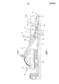
Фиг. 1 - дорожная фрезерная машина с передней погрузкой,FIG. 1 - road milling machine with front loading,
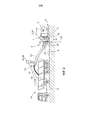
Фиг. 2 - дорожная фрезерная машина с задней погрузкой,FIG. 2 - road milling machine with rear loading,
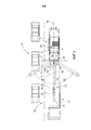
Фиг. 3 - вид сверху фрезерной машины согласно Фиг. 1 иFIG. 3 is a plan view of the milling machine of FIG. 1 and
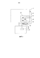
Фиг. 4 - принципиальная схема контроллера и системы регистрации изображений.FIG. 4 is a schematic diagram of a controller and an image registration system.
Фиг. 1 изображает фрезерную машину с использованием в качестве примера дорожной фрезерной машины 1a с передней погрузкой. Дорожная фрезерная машина 1 содержит раму 2 машины, которая поддерживается на шасси 4, состоящем, например, из гусеничных входящих в зацепление с землей блоков или колес, при этом указанное шасси 4 связано с рамой 2 машины посредством по меньшей мере трех устройств регулирования высоты в форме подъемных колонн 5. Как можно заключить из Фиг. 1, в варианте осуществления оговорены четыре подъемные колонны 5, которые могут использоваться для приведения рамы 2 машины в задаваемую плоскость, проходящую предпочтительно параллельно поверхности 6 дороги, которая поддерживает гусеничные входящих в зацепление с землей блоки или колеса шасси 4.FIG. 1 depicts a milling machine using, as an example, a front-loading road milling machine 1a. The
Дорожная фрезерная машина, показанная на Фиг. 1, содержит, в продольном направлении фрезерной машины 1a, рабочий барабан 22 между гусеничными входящими в зацепление с землей блоками шасси 4.The road milling machine shown in FIG. 1, comprises, in the longitudinal direction of the milling machine 1a, a working
Фрезерные машины 1a, 1b могут содержать гусеничные входящие в зацепление с землей блоки и/или колеса. Рабочий барабан может регулироваться по высоте посредством подъемных колонн 5, поддерживающих раму 2 машины, или относительно рамы 2 машины.
Другие конструкции фрезерной машины 1b также могут демонстрировать рабочий барабан 22, например, на высоте задних гусеничных входящих в зацепление с землей блоков или колес шасси 4. Other designs of the
Транспортировочное конвейерное устройство по меньшей мере с одним транспортировочным конвейером 11, 12 для транспортировки снятого фрезой сфрезерованного материала также может располагаться на переднем конце 7 или заднем конце 8 фрезерной машины 1a, 1b.A conveyor conveyor device with at least one
Фиг. 2 в качестве примера изображает фрезерную машину 1b с задней загрузкой, при этом транспортное средство 10 движется позади фрезерной машины задним ходом.FIG. 2 shows, by way of example, a rear
При условии, что со стороны рядом с фрезерной машиной 1a, 1b доступно достаточное пространство, транспортное средство 10 также может передвигаться вслед за фрезерной машиной 1 при продвижении вперед, как показано на Фиг. 3. Направления движения соответствующих транспортных средств на фигурах 1-3 обозначены стрелками.Provided that sufficient space is available from the side adjacent to the
В варианте осуществления, показанном на Фиг. 1, сфрезерованный материал, снятый рабочим барабаном 22, выгружается на погрузочную поверхность 15 транспортного средства 10 посредством первого постоянного установленного транспортировочного конвейера 11 транспортировочного конвейерного устройства, который передает сфрезерованный материал 14 на второй поворачивающейся транспортировочный конвейер 12. В результате скорости транспортировочного конвейера 12, сфрезерованный материал 14 не выгружается немедленно на конце транспортировочного конвейера 12, но сфрезерованный материал следует по параболической траектории, так что точка падения 16 на погрузочной поверхности 15 находится на расстоянии от свободного конца 13 транспортировочного конвейера 12. Транспортировочный конвейер 12 может поворачиваться из нейтрального положения влево или вправо посредством блоков 18 поршневых цилиндров для того, чтобы иметь возможность выгрузки сфрезерованного материала 14 на погрузочную поверхность 15, даже при движении на повороте или в случае транспортного средства 10, движущегося по смещенной колее. В дополнение, водитель транспортного средства фрезерной машины 1a, 1b посредством блока 20 поршневых цилиндров может регулировать угол подъема транспортировочного конвейера 12. Угол подъема оказывает влияние на параболическую траекторию сфрезерованного материала 14 и на положение точки 16 падения, так как имеется скорость транспортировки транспортировочного конвейера 12.In the embodiment shown in FIG. 1, the milled material removed by the working
Отрегулированный теперь угол подъема вокруг горизонтальной первой оси 21 или угол поворота вокруг вертикальной второй оси 23, соответственно, сообщаются в систему 24 обнаружения и управления, которая дополнительно содержит по меньшей мере одну систему 28 регистрации изображений, содержащую по меньшей мере один датчик 26, или связана с ним, при этом указанный датчик 26 непрерывно обнаруживает положение погрузочной поверхности 15 и/или транспортировочного конвейера 12. Указанный по меньшей мере один датчик 26 может быть расположен, например, на фрезерной машине 1a, 1b, на конце, обращенном к транспортировочному конвейеру 12, и/или на свободном конце 13 транспортировочного конвейера 12. Кроме того, датчик 26, предпочтительно датчик изображения, может быть расположен ниже или, как показано на фигурах, выше транспортировочного конвейера 12, а также в боковом направлении на обеих сторонах транспортировочного конвейера 12.The angle of rotation now adjusted around the horizontal
Блок 24 обнаружения и управления непрерывно обнаруживает положение погрузочной поверхности 15 и/или последнего или единственного транспортировочного конвейера 12, если смотреть в направлении транспортировки посредством системы 28 регистрации изображений или не оптической электронной системы размещения, которая поставляет данные для определения положения погрузочной поверхности 15 относительно рамы 2 машины или транспортировочного конвейера 12. По меньшей мере одно цифровое изображение 48, предоставляемое системой 28 регистрации изображений, может оцениваться посредством методов анализа изображений, которые известны сами по себе.The detection and
Блок 24 обнаружения и управления может быть встроен в контроллер 3 для операции перемещения и фрезерования или по меньшей мере может быть с ним связан для того, чтобы в случае возникновения необходимости также получать данные о скорости движения и/или обнаруженном угле поворота рулевого колеса фрезерной машины 1a, 1b и скорости транспортировки транспортировочного конвейера 12.The detection and
Блок 24 обнаружения и управления локализует изменяющееся положение погрузочной поверхности 15 транспортного средства 10 и транспортировочного конвейера 12 относительно рамы 2 машины, и может непрерывно и автоматически регулировать расположение точки падения 16 сфрезерованного материала 14 посредством угла поворота и/или угла подъема и/или скорости транспортировки транспортировочного конвейера 12, так чтобы выгружаемый сфрезерованный материал 14 падал, по меньшей мере, в пределах погрузочной поверхности 15. В качестве альтернативы, изменяющееся положение погрузочной поверхности 15 транспортного средства 10 также может непрерывно определяться относительно транспортировочного конвейера 12 для того, чтобы предпочтительно осуществлять процесс автоматического управления.The detection and
Для улучшения надежности процесса управления и избегания ошибок управления, блок 24 обнаружения и управления содержит анализирующее устройство 40, которое анализирует дефекты или ошибки в цифровом изображении 48, которое генерируется системой 28 регистрации изображений, содержащей по меньшей мере один датчик 26.To improve the reliability of the control process and avoid control errors, the detection and
Система 28 регистрации изображений может выйти из строя в результате погодных условий, например, в результате качающихся ветвей деревьев, в результате яркого света или также в результате электричества и неисправности системы, так что автоматическое управление машиной и в частности автоматическое регулирование угла поворота транспортировочного конвейера 12, таким образом, по меньшей мере временно может быть ухудшено.The
Анализирующее устройство 40 может анализировать пиксели цифрового изображения 48, генерируемого датчиком 26, и в случае обнаруженных дефектов или ошибок, генерировать предупреждающий сигнал или управляющий сигнал 46, который может непосредственно влиять на контроллер 3, или генерировать звуковой или зрительный предупреждающий сигнал, например, на экране 44, который отображает цифровое изображение 48 для оператора фрезерной машины 1.The analyzing
В случае предупреждающего сигнала может быть привлечено внимание оператора, так что оператор может изучать и отслеживать процесс автоматического управления при наличии предупреждающего сигнала 46.In the case of a warning signal, operator attention may be drawn so that the operator can study and monitor the automatic control process in the presence of a
В качестве альтернативы, также может быть прямое вмешательство в контроллер 3 посредством управляющего сигнала 47, генерируемого анализирующим устройством 40 для того, чтобы, например, остановить операцию фрезерования или для того, чтобы остановить транспортировочный конвейер 12 или для того, чтобы сгенерировать сигнал экстренной остановки.Alternatively, there may also be a direct intervention in the
Анализирующее устройство 40 дополнительно может быть связано с устройством 42 обнаружения фиксированного изображения, которое отслеживает неосуществление или изменение с течением времени сигналов изображения пикселей изображения датчика 26 в цифровом изображении 48.The analyzing
Устройство 42 обнаружения фиксированного изображения также может отслеживать изменение с течением времени метки 50, присутствующей в поле цифрового изображения 48 и изменяющейся определенным образом. Указанная метка 50 предназначена для изменения с течением времени в оговоренном ритме, так что зафиксированное изображение может быть идентифицировано, если не возникает указанное изменение метки 50 в определенной секции поля изображения.The fixed
В случае наличия двух датчиков 26, направленных на одно и то же поле изображения, зафиксированное изображение может также быть обнаружено, если изображение 48 одного датчика отличается от другого изображения 48 второго датчика.If there are two
Независимо от обнаружения фиксированных изображений, анализирующее устройство 40 может также отслеживать пиксели изображения по меньшей мере одного датчика 26 для неизменной информации об изображении и подавать предупреждающий сигнал или управляющий сигнал 46, если часть информации об изображении остается неизменной в течение оговоренного периода времени. Это может произойти, например, если часть датчика 26 закрыта, например, листьями.Regardless of the detection of fixed images, the
Независимо от обнаружения фиксированных изображений, дополнительно может анализироваться посредством анализирующего устройства 40, имеется ли нежелательное изменение в положении по меньшей мере одного датчика 26.Regardless of the detection of fixed images, it can be further analyzed by an analyzing
В связи с этим, в поле изображения 48 может быть оговорена вторая метка 52, координаты которой внутри поля изображения отслеживаются. Если положение метки 52 в пределах поля изображения изменяется, датчик изображения 26 изменился в результате, например, столкновения с объектом.In this regard, in the
Должно быть понятно, что для данных целей также может использоваться изменяющаяся метка 50.It should be understood that a
Метки 50, 52 расположены в фиксированном положении на раме машины или в фиксированном положении относительно транспортировочного конвейера таким образом, чтобы они обнаруживались полем изображения датчика 26.
Анализирующее устройство 40 независимо от обнаружения фиксированных изображений также может определять, подвергается ли система 28 регистрации изображений воздействию яркого света. В связи с этим, отслеживается максимальный сигнал, по меньшей мере, в части пикселей изображения, при этом анализирующее устройство 40 в случае яркого света подает предупреждающий сигнал или управляющий сигнал.The analyzing
В случае яркого света, может быть осуществлено электронное или оптическое затемнение датчика 26 или его оптической системы.In the case of bright light, electronic or optical dimming of the
В качестве альтернативы, в случае яркого света также может быть оговорен поворот датчика 26 или камеры, в которой заключен датчик 26, соответственно, на небольшую угловую величину без значительного изменения обнаруженного поля изображения. Указанное небольшое поворотное движение может быть снова изменено на обратное в случае прекращения яркого света.Alternatively, in the case of bright light, rotation of the
Должно быть понятно, что датчик 26 или система 28 регистрации изображений, соответственно, проиллюстрирован только схематично в положении выше транспортировочного конвейера 12, показанного на фигурах 1 и 2, и что система 28 регистрации изображений также может располагаться ниже или в сторону транспортировочного конвейера 12 или на фрезерной машине 1.It should be understood that the
Конкретно, на обеих сторонах транспортировочного конвейера 12 также могут располагаться две системы 28 регистрации изображений, и/или может использоваться система 28 регистрации изображений, которая содержит стерео камеру.Specifically, on both sides of the
В данном расположении, система камер может содержать оптические устройства (линзы типа рыбий глаз), которые допускают угол изображения до 180°, или снабжены линзами, имеющими отличительный признак в виде изменяющейся фокальной длины.In this arrangement, the camera system may contain optical devices (fisheye lenses) that allow an image angle of up to 180 °, or provided with lenses having a hallmark in the form of a varying focal length.
Блок 24 обнаружения и управления также может осуществлять задачу заполнения погрузочной поверхности 15 равномерным образом. Для данной цели может быть оговорена программа погрузки для того, чтобы загружать погрузочную поверхность 15 в соответствии с предварительно заданной программой. В данном контексте, состояние заполнения на погрузочной поверхности 15 может выявляться и анализироваться системой 28 регистрации изображений для того, чтобы непрерывно регулировать скорость транспортировки и/или положение разгрузочного конца 13 транспортировочного конвейера 12 относительно погрузочной поверхности 15.The detection and
Claims (28)
Applications Claiming Priority (2)
| Application Number | Priority Date | Filing Date | Title |
|---|---|---|---|
| DE102014216763.9A DE102014216763B4 (en) | 2014-08-22 | 2014-08-22 | Self-propelled milling machine, as well as method for unloading milled material |
| DE102014216763.9 | 2014-08-22 |
Publications (2)
| Publication Number | Publication Date |
|---|---|
| RU2015135360A RU2015135360A (en) | 2017-02-28 |
| RU2631747C2 true RU2631747C2 (en) | 2017-09-26 |
Family
ID=54056073
Family Applications (1)
| Application Number | Title | Priority Date | Filing Date |
|---|---|---|---|
| RU2015135360A RU2631747C2 (en) | 2014-08-22 | 2015-08-20 | Mobile cutting machine and unloading method for milled off material |
Country Status (8)
| Country | Link |
|---|---|
| US (1) | US9764910B2 (en) |
| EP (1) | EP2987912B1 (en) |
| JP (1) | JP6050446B2 (en) |
| CN (2) | CN204875465U (en) |
| AU (1) | AU2015215934B2 (en) |
| CA (1) | CA2901039C (en) |
| DE (1) | DE102014216763B4 (en) |
| RU (1) | RU2631747C2 (en) |
Families Citing this family (20)
| Publication number | Priority date | Publication date | Assignee | Title |
|---|---|---|---|---|
| DE102014216763B4 (en) | 2014-08-22 | 2018-07-26 | Wirtgen Gmbh | Self-propelled milling machine, as well as method for unloading milled material |
| US20170130405A1 (en) * | 2015-11-05 | 2017-05-11 | Caterpillar Paving Products Inc. | Truck position control system for milling operations |
| WO2017125607A1 (en) | 2016-01-21 | 2017-07-27 | Wirtgen Gmbh | System formed by a construction machine, transport vehicle with a loading space and image-capturing device, and method for displaying an image stream when loading or unloading a transport vehicle |
| US10688901B2 (en) * | 2016-03-23 | 2020-06-23 | Bomag Gmbh | Intermediate storage vehicle for milled material and work train |
| CN106120528B (en) * | 2016-06-17 | 2018-01-30 | 河海大学 | A kind of self-propelled concrete dabbing machine and its dabbing method |
| DE102016222145A1 (en) | 2016-11-11 | 2018-05-17 | Wirtgen Gmbh | System and method for tracking milled material |
| DE102016223454A1 (en) * | 2016-11-25 | 2018-05-30 | Wirtgen Gmbh | System and method for tracking milled material |
| US10927513B2 (en) | 2016-11-11 | 2021-02-23 | Wirtgen Gmbh | System and method for the tracking of milling material |
| DE102016222589B4 (en) | 2016-11-16 | 2020-01-16 | Wirtgen Gmbh | Self-propelled milling machine and method for controlling a self-propelled milling machine |
| GB2565851B (en) * | 2017-08-25 | 2022-05-04 | Haldex Brake Prod Ab | Braking system |
| CN108221610A (en) * | 2018-03-14 | 2018-06-29 | 徐州徐工筑路机械有限公司 | A kind of milling machine automatically transporting materials system of view-based access control model identification |
| US10428471B1 (en) * | 2018-05-22 | 2019-10-01 | Caterpillar Paving Products Inc. | Systems and methods for controlling cold planer material flow |
| EP3832019B1 (en) * | 2018-08-03 | 2023-08-30 | Sumitomo (S.H.I.) Construction Machinery Co., Ltd. | Asphalt finisher and asphalt finisher monitoring system |
| JP7197310B2 (en) * | 2018-08-31 | 2022-12-27 | 株式会社小松製作所 | Loading machine control device and control method |
| DE102019104218A1 (en) | 2019-02-19 | 2020-08-20 | Wirtgen Gmbh | Work train, comprising a tillage machine and another vehicle as well as an automated distance monitoring |
| US20210191413A1 (en) * | 2019-12-18 | 2021-06-24 | Caterpillar Paving Products Inc. | Machine Sunk Detection System and Method |
| US11390263B2 (en) * | 2020-05-04 | 2022-07-19 | Deere & Company | Forage harvester with automatic detection of receiving vehicle |
| CN111764214A (en) * | 2020-07-15 | 2020-10-13 | 湖南省交建工程集团有限公司 | Three-dimensional reinforcement treatment construction method for soft soil roadbed geotechnical synthetic material |
| US11192730B1 (en) * | 2020-08-12 | 2021-12-07 | Caterpillar Paving Products Inc. | Material transfer system for machine |
| CN113463718A (en) * | 2021-06-30 | 2021-10-01 | 广西柳工机械股份有限公司 | Anti-collision control system and control method for loader |
Citations (4)
| Publication number | Priority date | Publication date | Assignee | Title |
|---|---|---|---|---|
| EP1344445A1 (en) * | 2002-03-13 | 2003-09-17 | Deere & Company | Image processing spout control system |
| EP1959056A2 (en) * | 2007-02-17 | 2008-08-20 | Wirtgen GmbH | Construction machine, in particular a road construction machine |
| RU2394122C1 (en) * | 2006-04-27 | 2010-07-10 | Виртген Гмбх | Machine for road construction, levelling device, as well as control method of depth of milling or inclination of milling of machine for road construction |
| DE102012215013A1 (en) * | 2012-08-23 | 2014-02-27 | Wirtgen Gmbh | Self-propelled milling machine, as well as method for unloading milled material |
Family Cites Families (35)
| Publication number | Priority date | Publication date | Assignee | Title |
|---|---|---|---|---|
| DE155157C (en) | 1904-11-01 | |||
| US3608968A (en) | 1969-04-03 | 1971-09-28 | Christensen Diamond Prod Co | Pavement cutting and water and cutting pickup apparatus |
| US4376609A (en) | 1980-03-31 | 1983-03-15 | Sperry Corporation | Automatic spout control for agricultural machines |
| DD155157A1 (en) | 1980-12-09 | 1982-05-19 | Bernd Kaempfe | POSITIONING DEVICE, IN PARTICULAR BETWEEN RE-ESTATE MACHINERY AND TRANSPORT VEHICLES |
| US4863009A (en) | 1988-11-14 | 1989-09-05 | Alberta Energy Company Ltd. | Control system for an endless belt conveyor train |
| DE4403893A1 (en) | 1994-02-08 | 1995-08-10 | Claas Ohg | Device for the automatic filling of loading containers with a stream of material |
| DE19531662A1 (en) | 1995-08-29 | 1997-03-06 | Claas Ohg | Device for the automatic filling of loading containers |
| DE19628420C2 (en) | 1996-07-15 | 1999-07-29 | Krupp Foerdertechnik Gmbh | Process for material degradation using a bucket wheel excavator |
| JPH11211438A (en) * | 1998-01-22 | 1999-08-06 | Komatsu Ltd | Load carrying platform load volume measuring device |
| WO1999052068A1 (en) | 1998-04-03 | 1999-10-14 | Koninklijke Philips Electronics N.V. | Image processing method and system involving contour detection steps |
| DE19848127A1 (en) | 1998-10-19 | 2000-04-20 | Claas Selbstfahr Erntemasch | Device for controlling a transfer device |
| US6682416B2 (en) | 2000-12-23 | 2004-01-27 | Claas Selbstfahrende Erntemaschinen Gmbh | Automatic adjustment of a transfer device on an agricultural harvesting machine |
| DE10203732A1 (en) | 2002-01-30 | 2003-08-21 | Wirtgen Gmbh | Construction machinery |
| DE102004007716B3 (en) | 2004-02-16 | 2005-06-16 | Wirtgen Gmbh | Road construction asphalt milling machine has dust suction unit located well away from rotating milling tool |
| DE102004011789A1 (en) | 2004-03-09 | 2005-09-29 | Claas Selbstfahrende Erntemaschinen Gmbh | Device for detecting a loading wagon |
| US20060045621A1 (en) | 2004-08-27 | 2006-03-02 | Caterpillar Paving Products Inc. | Asphalt-removing work machine having a storage bin |
| DE102005035480A1 (en) | 2005-07-26 | 2007-02-01 | Cft Gmbh Compact Filter Technic | Milling machine for road coverings comprises a dust box arranged in front of a ventilator and assigned to a suction channel having an outlet for passing clean waste air directly into the atmosphere |
| FI120191B (en) | 2005-10-03 | 2009-07-31 | Sandvik Tamrock Oy | A method for driving mining vehicles in a mine and a transportation system |
| DE102007009666A1 (en) | 2007-02-22 | 2008-08-28 | Carl Zeiss Microimaging Gmbh | Arrangement for filling a container with bulk material |
| WO2008115560A1 (en) | 2007-03-20 | 2008-09-25 | Volvo Construction Equipment Ab | Milling machine with cutter drum speed control |
| DE202007005756U1 (en) * | 2007-04-19 | 2008-08-28 | Wirtgen Gmbh | Self-propelled construction machine |
| ATE546991T1 (en) | 2007-08-03 | 2012-03-15 | Agrocom Gmbh & Co Agrarsystem Kg | AGRICULTURAL WORKING MACHINE |
| DE102008008260B4 (en) | 2008-02-08 | 2010-09-09 | Wirtgen Gmbh | Control of a mining machine and mining machine |
| DE102008014001A1 (en) | 2008-03-13 | 2009-09-17 | Claas Selbstfahrende Erntemaschinen Gmbh | Agricultural harvester with a transfer device |
| DE102008021484B4 (en) | 2008-04-29 | 2010-01-28 | Wirtgen Gmbh | Bendable conveyor belt for a construction machine, self-propelled construction machine and method for pivoting a conveyor belt |
| EP2256246B1 (en) | 2009-05-20 | 2018-07-04 | Joseph Vögele AG | Paving machines for applying a cover layer of a road surface |
| EP2311307B1 (en) | 2009-09-07 | 2011-12-07 | CLAAS Agrosystems GmbH & Co. KG | A filling degree gauge, an agricultural vehicle comprising such gauge, and a method of controlling filling of a target area |
| ATE533350T1 (en) | 2009-09-07 | 2011-12-15 | Claas Agrosystems Gmbh & Co Kg | CONTROL SYSTEM OF AN AGRICULTURAL VEHICLE WITH A GOODS CARRIER, AGRICULTURAL VEHICLE AND METHOD FOR CONTROLLING A GOODS CARRIER OF THE AGRICULTURAL VEHICLE |
| DE102009041842A1 (en) | 2009-09-18 | 2011-09-01 | Wirtgen Gmbh | Self-propelled road milling machine |
| DE102010043854B4 (en) | 2010-11-12 | 2016-01-14 | Deere & Company | Control arrangement for controlling the transfer of agricultural crop from a harvester to a transport vehicle |
| DE102011082052B4 (en) | 2011-09-02 | 2015-05-28 | Deere & Company | Arrangement and method for the automatic overloading of crop material from a harvester onto a transport vehicle |
| DE102011114183A1 (en) | 2011-09-22 | 2013-03-28 | Bomag Gmbh | Method for controlling a loading process of a transport vehicle with milled material, device for carrying out such a method and milling device |
| DE102011114185A1 (en) | 2011-09-22 | 2013-03-28 | Bomag Gmbh | Work train with a milling device and a transport device with a sensor device for distance monitoring, milling device with a sensor device and method for distance monitoring in a work train |
| DE102012215005A1 (en) | 2012-08-23 | 2014-02-27 | Wirtgen Gmbh | Self-propelled milling machine, as well as method for steering a self-propelled milling machine |
| DE102014216763B4 (en) | 2014-08-22 | 2018-07-26 | Wirtgen Gmbh | Self-propelled milling machine, as well as method for unloading milled material |
-
2014
- 2014-08-22 DE DE102014216763.9A patent/DE102014216763B4/en not_active Expired - Fee Related
-
2015
- 2015-08-17 US US14/827,450 patent/US9764910B2/en active Active
- 2015-08-18 EP EP15181355.7A patent/EP2987912B1/en active Active
- 2015-08-19 CA CA2901039A patent/CA2901039C/en active Active
- 2015-08-20 RU RU2015135360A patent/RU2631747C2/en active
- 2015-08-21 AU AU2015215934A patent/AU2015215934B2/en active Active
- 2015-08-21 JP JP2015163809A patent/JP6050446B2/en active Active
- 2015-08-24 CN CN201520643133.0U patent/CN204875465U/en not_active Withdrawn - After Issue
- 2015-08-24 CN CN201510523921.0A patent/CN105386394B/en active Active
Patent Citations (4)
| Publication number | Priority date | Publication date | Assignee | Title |
|---|---|---|---|---|
| EP1344445A1 (en) * | 2002-03-13 | 2003-09-17 | Deere & Company | Image processing spout control system |
| RU2394122C1 (en) * | 2006-04-27 | 2010-07-10 | Виртген Гмбх | Machine for road construction, levelling device, as well as control method of depth of milling or inclination of milling of machine for road construction |
| EP1959056A2 (en) * | 2007-02-17 | 2008-08-20 | Wirtgen GmbH | Construction machine, in particular a road construction machine |
| DE102012215013A1 (en) * | 2012-08-23 | 2014-02-27 | Wirtgen Gmbh | Self-propelled milling machine, as well as method for unloading milled material |
Also Published As
| Publication number | Publication date |
|---|---|
| CN105386394B (en) | 2018-03-09 |
| US20160052731A1 (en) | 2016-02-25 |
| JP2016044546A (en) | 2016-04-04 |
| JP6050446B2 (en) | 2016-12-21 |
| CA2901039A1 (en) | 2016-02-22 |
| EP2987912B1 (en) | 2017-05-31 |
| AU2015215934B2 (en) | 2017-02-02 |
| CN204875465U (en) | 2015-12-16 |
| DE102014216763B4 (en) | 2018-07-26 |
| CN105386394A (en) | 2016-03-09 |
| RU2015135360A (en) | 2017-02-28 |
| DE102014216763A1 (en) | 2016-02-25 |
| EP2987912A1 (en) | 2016-02-24 |
| AU2015215934A1 (en) | 2016-03-10 |
| US9764910B2 (en) | 2017-09-19 |
| CA2901039C (en) | 2017-09-12 |
Similar Documents
| Publication | Publication Date | Title |
|---|---|---|
| RU2631747C2 (en) | Mobile cutting machine and unloading method for milled off material | |
| US10947677B2 (en) | Automotive milling machine, as well as method for unloading milled material | |
| RU2611802C2 (en) | Self-propelled milling machine and method of milled material unloading | |
| US10377311B2 (en) | Automotive construction machine and method for displaying the surroundings of an automotive construction machine | |
| US20140054949A1 (en) | Automotive Milling Machine, As Well As Method For Steering An Automotive Milling Machine | |
| US10753052B2 (en) | Self-propelled milling machine, as well as method for controlling a self-propelled milling machine | |
| CN104220351A (en) | Method and stereo vision system for facilitating the unloading of agricultural material from a vehicle | |
| RU2620675C2 (en) | Self-powered milling machine, and the way to remove milled off material |