RU2624679C1 - Refrigerator - Google Patents
Refrigerator Download PDFInfo
- Publication number
- RU2624679C1 RU2624679C1 RU2016107823A RU2016107823A RU2624679C1 RU 2624679 C1 RU2624679 C1 RU 2624679C1 RU 2016107823 A RU2016107823 A RU 2016107823A RU 2016107823 A RU2016107823 A RU 2016107823A RU 2624679 C1 RU2624679 C1 RU 2624679C1
- Authority
- RU
- Russia
- Prior art keywords
- temperature
- flow resistance
- flow
- refrigerator
- refrigeration circuit
- Prior art date
Links
- 238000005057 refrigeration Methods 0.000 claims abstract description 33
- 238000009833 condensation Methods 0.000 claims description 85
- 239000003507 refrigerant Substances 0.000 claims description 74
- 238000005192 partition Methods 0.000 claims description 20
- 239000000126 substance Substances 0.000 abstract 1
- 239000003570 air Substances 0.000 description 34
- 238000001816 cooling Methods 0.000 description 26
- 230000005494 condensation Effects 0.000 description 18
- 238000009434 installation Methods 0.000 description 9
- 238000010586 diagram Methods 0.000 description 6
- 235000013311 vegetables Nutrition 0.000 description 6
- 230000007704 transition Effects 0.000 description 4
- 238000010438 heat treatment Methods 0.000 description 3
- 238000010276 construction Methods 0.000 description 2
- 230000007423 decrease Effects 0.000 description 2
- 239000002274 desiccant Substances 0.000 description 2
- 239000000428 dust Substances 0.000 description 2
- 238000005265 energy consumption Methods 0.000 description 2
- 238000007710 freezing Methods 0.000 description 2
- 230000008014 freezing Effects 0.000 description 2
- 239000011810 insulating material Substances 0.000 description 2
- 239000002184 metal Substances 0.000 description 2
- 229910052751 metal Inorganic materials 0.000 description 2
- 238000012544 monitoring process Methods 0.000 description 2
- 239000000843 powder Substances 0.000 description 2
- RYGMFSIKBFXOCR-UHFFFAOYSA-N Copper Chemical compound [Cu] RYGMFSIKBFXOCR-UHFFFAOYSA-N 0.000 description 1
- JOYRKODLDBILNP-UHFFFAOYSA-N Ethyl urethane Chemical compound CCOC(N)=O JOYRKODLDBILNP-UHFFFAOYSA-N 0.000 description 1
- 238000010521 absorption reaction Methods 0.000 description 1
- 239000012080 ambient air Substances 0.000 description 1
- 230000015572 biosynthetic process Effects 0.000 description 1
- 125000000484 butyl group Chemical group [H]C([*])([H])C([H])([H])C([H])([H])C([H])([H])[H] 0.000 description 1
- 238000004364 calculation method Methods 0.000 description 1
- 230000006835 compression Effects 0.000 description 1
- 238000007906 compression Methods 0.000 description 1
- 229910052802 copper Inorganic materials 0.000 description 1
- 239000010949 copper Substances 0.000 description 1
- 230000003247 decreasing effect Effects 0.000 description 1
- 230000005611 electricity Effects 0.000 description 1
- 239000004973 liquid crystal related substance Substances 0.000 description 1
- 239000000463 material Substances 0.000 description 1
- 230000002093 peripheral effect Effects 0.000 description 1
- 230000001105 regulatory effect Effects 0.000 description 1
- 238000000926 separation method Methods 0.000 description 1
- 238000011144 upstream manufacturing Methods 0.000 description 1
Images

Classifications
-
- F—MECHANICAL ENGINEERING; LIGHTING; HEATING; WEAPONS; BLASTING
- F25—REFRIGERATION OR COOLING; COMBINED HEATING AND REFRIGERATION SYSTEMS; HEAT PUMP SYSTEMS; MANUFACTURE OR STORAGE OF ICE; LIQUEFACTION SOLIDIFICATION OF GASES
- F25D—REFRIGERATORS; COLD ROOMS; ICE-BOXES; COOLING OR FREEZING APPARATUS NOT OTHERWISE PROVIDED FOR
- F25D11/00—Self-contained movable devices, e.g. domestic refrigerators
- F25D11/02—Self-contained movable devices, e.g. domestic refrigerators with cooling compartments at different temperatures
-
- F—MECHANICAL ENGINEERING; LIGHTING; HEATING; WEAPONS; BLASTING
- F25—REFRIGERATION OR COOLING; COMBINED HEATING AND REFRIGERATION SYSTEMS; HEAT PUMP SYSTEMS; MANUFACTURE OR STORAGE OF ICE; LIQUEFACTION SOLIDIFICATION OF GASES
- F25D—REFRIGERATORS; COLD ROOMS; ICE-BOXES; COOLING OR FREEZING APPARATUS NOT OTHERWISE PROVIDED FOR
- F25D29/00—Arrangement or mounting of control or safety devices
-
- F—MECHANICAL ENGINEERING; LIGHTING; HEATING; WEAPONS; BLASTING
- F25—REFRIGERATION OR COOLING; COMBINED HEATING AND REFRIGERATION SYSTEMS; HEAT PUMP SYSTEMS; MANUFACTURE OR STORAGE OF ICE; LIQUEFACTION SOLIDIFICATION OF GASES
- F25B—REFRIGERATION MACHINES, PLANTS OR SYSTEMS; COMBINED HEATING AND REFRIGERATION SYSTEMS; HEAT PUMP SYSTEMS
- F25B41/00—Fluid-circulation arrangements
- F25B41/30—Expansion means; Dispositions thereof
- F25B41/31—Expansion valves
- F25B41/34—Expansion valves with the valve member being actuated by electric means, e.g. by piezoelectric actuators
-
- F—MECHANICAL ENGINEERING; LIGHTING; HEATING; WEAPONS; BLASTING
- F25—REFRIGERATION OR COOLING; COMBINED HEATING AND REFRIGERATION SYSTEMS; HEAT PUMP SYSTEMS; MANUFACTURE OR STORAGE OF ICE; LIQUEFACTION SOLIDIFICATION OF GASES
- F25D—REFRIGERATORS; COLD ROOMS; ICE-BOXES; COOLING OR FREEZING APPARATUS NOT OTHERWISE PROVIDED FOR
- F25D21/00—Defrosting; Preventing frosting; Removing condensed or defrost water
- F25D21/04—Preventing the formation of frost or condensate
-
- F—MECHANICAL ENGINEERING; LIGHTING; HEATING; WEAPONS; BLASTING
- F25—REFRIGERATION OR COOLING; COMBINED HEATING AND REFRIGERATION SYSTEMS; HEAT PUMP SYSTEMS; MANUFACTURE OR STORAGE OF ICE; LIQUEFACTION SOLIDIFICATION OF GASES
- F25D—REFRIGERATORS; COLD ROOMS; ICE-BOXES; COOLING OR FREEZING APPARATUS NOT OTHERWISE PROVIDED FOR
- F25D29/00—Arrangement or mounting of control or safety devices
- F25D29/003—Arrangement or mounting of control or safety devices for movable devices
-
- F—MECHANICAL ENGINEERING; LIGHTING; HEATING; WEAPONS; BLASTING
- F25—REFRIGERATION OR COOLING; COMBINED HEATING AND REFRIGERATION SYSTEMS; HEAT PUMP SYSTEMS; MANUFACTURE OR STORAGE OF ICE; LIQUEFACTION SOLIDIFICATION OF GASES
- F25B—REFRIGERATION MACHINES, PLANTS OR SYSTEMS; COMBINED HEATING AND REFRIGERATION SYSTEMS; HEAT PUMP SYSTEMS
- F25B1/00—Compression machines, plants or systems with non-reversible cycle
-
- F—MECHANICAL ENGINEERING; LIGHTING; HEATING; WEAPONS; BLASTING
- F25—REFRIGERATION OR COOLING; COMBINED HEATING AND REFRIGERATION SYSTEMS; HEAT PUMP SYSTEMS; MANUFACTURE OR STORAGE OF ICE; LIQUEFACTION SOLIDIFICATION OF GASES
- F25B—REFRIGERATION MACHINES, PLANTS OR SYSTEMS; COMBINED HEATING AND REFRIGERATION SYSTEMS; HEAT PUMP SYSTEMS
- F25B2600/00—Control issues
- F25B2600/02—Compressor control
- F25B2600/025—Compressor control by controlling speed
- F25B2600/0251—Compressor control by controlling speed with on-off operation
-
- F—MECHANICAL ENGINEERING; LIGHTING; HEATING; WEAPONS; BLASTING
- F25—REFRIGERATION OR COOLING; COMBINED HEATING AND REFRIGERATION SYSTEMS; HEAT PUMP SYSTEMS; MANUFACTURE OR STORAGE OF ICE; LIQUEFACTION SOLIDIFICATION OF GASES
- F25B—REFRIGERATION MACHINES, PLANTS OR SYSTEMS; COMBINED HEATING AND REFRIGERATION SYSTEMS; HEAT PUMP SYSTEMS
- F25B2700/00—Sensing or detecting of parameters; Sensors therefor
- F25B2700/21—Temperatures
- F25B2700/2106—Temperatures of fresh outdoor air
-
- F—MECHANICAL ENGINEERING; LIGHTING; HEATING; WEAPONS; BLASTING
- F25—REFRIGERATION OR COOLING; COMBINED HEATING AND REFRIGERATION SYSTEMS; HEAT PUMP SYSTEMS; MANUFACTURE OR STORAGE OF ICE; LIQUEFACTION SOLIDIFICATION OF GASES
- F25D—REFRIGERATORS; COLD ROOMS; ICE-BOXES; COOLING OR FREEZING APPARATUS NOT OTHERWISE PROVIDED FOR
- F25D2321/00—Details or arrangements for defrosting; Preventing frosting; Removing condensed or defrost water, not provided for in other groups of this subclass
-
- F—MECHANICAL ENGINEERING; LIGHTING; HEATING; WEAPONS; BLASTING
- F25—REFRIGERATION OR COOLING; COMBINED HEATING AND REFRIGERATION SYSTEMS; HEAT PUMP SYSTEMS; MANUFACTURE OR STORAGE OF ICE; LIQUEFACTION SOLIDIFICATION OF GASES
- F25D—REFRIGERATORS; COLD ROOMS; ICE-BOXES; COOLING OR FREEZING APPARATUS NOT OTHERWISE PROVIDED FOR
- F25D2700/00—Means for sensing or measuring; Sensors therefor
- F25D2700/14—Sensors measuring the temperature outside the refrigerator or freezer
-
- Y—GENERAL TAGGING OF NEW TECHNOLOGICAL DEVELOPMENTS; GENERAL TAGGING OF CROSS-SECTIONAL TECHNOLOGIES SPANNING OVER SEVERAL SECTIONS OF THE IPC; TECHNICAL SUBJECTS COVERED BY FORMER USPC CROSS-REFERENCE ART COLLECTIONS [XRACs] AND DIGESTS
- Y02—TECHNOLOGIES OR APPLICATIONS FOR MITIGATION OR ADAPTATION AGAINST CLIMATE CHANGE
- Y02B—CLIMATE CHANGE MITIGATION TECHNOLOGIES RELATED TO BUILDINGS, e.g. HOUSING, HOUSE APPLIANCES OR RELATED END-USER APPLICATIONS
- Y02B30/00—Energy efficient heating, ventilation or air conditioning [HVAC]
- Y02B30/70—Efficient control or regulation technologies, e.g. for control of refrigerant flow, motor or heating
Landscapes
- Engineering & Computer Science (AREA)
- Physics & Mathematics (AREA)
- Mechanical Engineering (AREA)
- Thermal Sciences (AREA)
- General Engineering & Computer Science (AREA)
- Chemical & Material Sciences (AREA)
- Combustion & Propulsion (AREA)
- Devices That Are Associated With Refrigeration Equipment (AREA)
Abstract
Description
Область техники, к которой относится изобретениеFIELD OF THE INVENTION
Настоящее изобретение относится к холодильнику, имеющему противоконденсатную трубку для предотвращения конденсации росы.The present invention relates to a refrigerator having an anti-condensation tube to prevent dew condensation.
Предпосылки изобретенияBACKGROUND OF THE INVENTION
Холодильник обычно включает в себя шкаф, который является теплоизоляционным корпусом с открытой передней стороной, перегородку для разделения внутреннего пространства шкафа на множество отделений для хранения и теплоизоляционные двери, которые закрывают передние отверстия соответствующих отделений для хранения таким образом, что они могут свободно открываться и закрываться. В холодильнике этого типа холодный воздух проходит между шкафом и перегородкой и теплоизоляционными дверями, уменьшая температуру поверхности кромки переднего отверстия шкафа. Когда температура поверхности опускается ниже температуры наружного воздуха и затем температуры точки росы или ниже, происходит конденсация росы. Для устранения этой проблемы противоконденсатная трубка, через которую проходит хладагент высокого давления, установлена на передних кромках шкафа и перегородки, которые являются отверстиями отделений для хранения холодильника, для устранения возникновения конденсации росы путем нагрева передних сторон шкафа и перегородки с использованием конденсационной теплоты хладагента, проходящего через противоконденсатную трубку.A refrigerator typically includes a cabinet, which is a heat-insulating enclosure with an open front side, a partition for dividing the interior of the cabinet into multiple storage compartments, and heat-insulating doors that close the front openings of the respective storage compartments so that they can open and close freely. In this type of refrigerator, cold air passes between the cabinet and the partition and the heat-insulating doors, reducing the surface temperature of the edge of the front opening of the cabinet. When the surface temperature drops below the outside temperature and then the dew point temperature or lower, dew condensation occurs. To eliminate this problem, the anti-condensation tube through which the high-pressure refrigerant passes is installed on the front edges of the cabinet and the partition, which are the openings of the refrigerator storage compartments, to eliminate the occurrence of dew condensation by heating the front sides of the cabinet and the partition using the condensation heat of the refrigerant passing through anti-condensation tube.
При этом, если противоконденсатная трубка чрезмерно нагревается, часть конденсационной теплоты проходит в отделения для хранения из противоконденсатной трубки, увеличивая тепловую нагрузку холодильника. Следовательно, был предложен холодильник, в котором скорость потока хладагента, проходящего через противоконденсатную трубку, или температура хладагента регулируются для предотвращения чрезмерного нагрева противоконденсатной трубки при предотвращении конденсации росы (например, см. патентные документы 1 и 2).Moreover, if the anti-condensation tube is excessively heated, part of the condensation heat passes into the storage compartments from the anti-condensation tube, increasing the heat load of the refrigerator. Therefore, a refrigerator has been proposed in which the flow rate of the refrigerant passing through the anti-condensation pipe or the temperature of the refrigerant is controlled to prevent excessive heating of the anti-condensation pipe while preventing dew condensation (for example, see
Патентный документ 1 раскрывает холодильник, в котором распределительное устройство скорости потока хладагента расположено между конденсатором, отводящим тепло, и противоконденсатным конденсатором. Распределительное устройство скорости потока хладагента распределяет хладагент в противоконденсатный конденсатор и перепускную трубу в зависимости от разности температур между температурой окружающего воздуха и противоконденсатным конденсатором. Патентный документ 2 раскрывает холодильник, в котором трубка конденсатора расположена на каждой из сторон вверх по потоку и вниз по потоку от конденсатора, и регулируемый расширительный клапан расположен между конденсатором и противоконденсатной трубкой на стороне вниз по потоку. Посредством регулирования расширительного клапана температура хладагента, проходящего в противоконденсатную трубку на стороне вниз по потоку, регулируется до оптимальной температуры.
Список противопоставленных материаловList of Contrasted Materials
Патентный документPatent document
Патентный документ 1: публикация №.8-285426 японской нерассмотренной патентной заявки (фиг.1)Patent Document 1: Publication No. 8-285426 of Japanese Unexamined Patent Application (FIG. 1)
Патентный документ 2: публикация №.54-21660 японской нерассмотренной патентной заявки (фиг.5)Patent Document 2: Publication No. 54-21660 of Japanese Unexamined Patent Application (FIG. 5)
Краткое описание настоящего изобретенияA brief description of the present invention
Техническая проблемаTechnical problem
Однако в холодильнике в патентном документе 1, поскольку скорость потока хладагента, проходящего в противоконденсатную трубку, изменяется, для регулировки температуры хладагента, проходящего в противоконденсатную трубку, до целевой температуры необходимы регулировочное устройство скорости потока и устройство определения давления для точного определения скорости потока и давления хладагента, проходящего в противоконденсатную трубку. Таким образом, себестоимость увеличивается, и требуется установка дополнительного компрессора, приводя к увеличению потребления электроэнергии. Кроме того, поскольку холодильник в патентном документе 2 требует расположения противоконденсатной трубки в положениях в зависимости от температур кромок отверстий отделений для хранения, имеющих разные температуры, конструкция и расположение противоконденсатной трубки становятся сложными.However, in the refrigerator in
Настоящее изобретение было осуществлено с учетом вышеописанных проблем, и его целью является создание холодильника, имеющего недорогую и простую конструкцию, обеспечивающую устранение увеличения тепловой нагрузки холодильника, обусловленной теплом противоконденсатной трубки.The present invention has been carried out in view of the above problems, and its purpose is to provide a refrigerator having an inexpensive and simple construction that can eliminate the increase in the heat load of the refrigerator due to the heat of the anti-condensation tube.
Решение проблемыSolution
Холодильник настоящего изобретения включает в себя шкаф, имеющий внутреннее пространство, перегородку для разделения внутреннего пространства шкафа на множество отделений для хранения, холодильный контур, размещенный в шкафу, причем холодильный контур соединяет последовательно по порядку компрессор, трубку конденсатора, устройство для понижения давления, противоконденсатную трубку и капиллярную трубку, датчик температуры наружного воздуха, установленный на наружной стороне шкафа и выполненный с возможностью определения температуры наружного воздуха, и контроллер, выполненный с возможностью управления работой холодильного контура. Контроллер включает в себя таблицу параметров, для хранения сопротивления потоку устройства для понижения давления, связанного с каждой из температур наружного воздуха, причем сопротивления потоку отличаются друг от друга, блок установки режима работы, выполненный с возможностью выбора одного из сопротивлений потоку из таблицы параметров на основании температуры наружного воздуха, определенного датчиком температуры наружного воздуха, и выполненный с возможностью установки рабочего времени для выбранного сопротивления потоку, и блок управления холодильным контуром, выполненный с возможностью управления холодильным контуром для обеспечения осуществления работы при сопротивлении потоку и рабочем времени, установленных блоком установки режима работы.The refrigerator of the present invention includes a cabinet having an interior space, a partition for dividing the cabinet interior space into a plurality of storage compartments, a refrigeration circuit disposed in the cabinet, the refrigeration circuit connecting in series with the compressor, the condenser tube, the pressure reducing device, the anti-condensation tube and a capillary tube, an outdoor temperature sensor mounted on the outside of the cabinet and configured to determine the temperature s outdoor air, and a controller adapted to control operation of the refrigeration circuit. The controller includes a table of parameters for storing the flow resistance of the device for lowering the pressure associated with each of the outdoor temperatures, the flow resistances being different from each other, an operation mode setting unit configured to select one of the flow resistances from the parameter table based on outdoor temperature detected by the outdoor temperature sensor, and configured to set the working time for the selected flow resistance, and control the refrigeration circuit adapted to control the refrigerating circuit to ensure operation of the flow resistance during working time and set by the operation mode setting unit.
Положительные результаты изобретенияThe positive results of the invention
В соответствии с холодильником настоящего изобретения посредством автоматической установки сопротивления потоку устройства для понижения давления и рабочего времени для него в зависимости от температуры наружного воздуха можно предотвратить конденсацию росы при устранении увеличения потребления электроэнергии вследствие тепла противоконденсатной трубки при использовании недорогой и простой конструкции без установки устройства для определения давления или перепускной трубы, необходимых в известной конфигурации.According to the refrigerator of the present invention, by automatically setting the flow resistance of the pressure reducing device and the operating time for it depending on the outdoor temperature, dew condensation can be prevented while eliminating the increase in power consumption due to the heat of the anti-condensation tube using an inexpensive and simple design without installing a device for determining pressure or bypass pipe required in a known configuration.
Краткое описание чертежейBrief Description of the Drawings
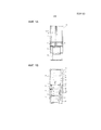
Фиг.1A – вид спереди предпочтительного варианта осуществления холодильника настоящего изобретения;1A is a front view of a preferred embodiment of a refrigerator of the present invention;
фиг.1B – вид в разрезе сбоку предпочтительного варианта осуществления холодильника настоящего изобретения;figv is a side sectional view of a preferred embodiment of a refrigerator of the present invention;
фиг.1C – вид спереди холодильника настоящего изобретения в соответствии с предпочтительным вариантом осуществления в положении без дверей;figs is a front view of the refrigerator of the present invention in accordance with a preferred embodiment in the position without doors;
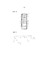
фиг.2 – схема циркуляции хладагента, изображающая пример холодильного контура холодильника на фиг.1;figure 2 is a diagram of the circulation of the refrigerant, depicting an example of the refrigeration circuit of the refrigerator in figure 1;
фиг.3 – вид в плане, изображающий пример противоконденсатной трубки, размещенной в шкафу на фиг.1;figure 3 is a plan view showing an example of an anti-condensation tube located in the cabinet of figure 1;
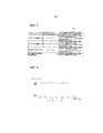
фиг.4 – функциональная блок-схема, изображающая пример контроллера холодильника на фиг.1;figure 4 is a functional block diagram depicting an example of the controller of the refrigerator in figure 1;
фиг.5 – таблица, изображающая пример таблицы параметров в контроллере на фиг.4;5 is a table showing an example of a parameter table in the controller of FIG. 4;
фиг.6 – кривая, показывающая регулировку степени открытия устройства для понижения давления во время работы холодильного контура на фиг.2;Fig.6 is a curve showing the adjustment of the degree of opening of the device for lowering pressure during operation of the refrigeration circuit in Fig.2;
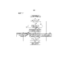
фиг.7 – схема последовательности действий, показывающая пример работы холодильника на фиг.1.Fig.7 is a sequence diagram showing an example of the operation of the refrigerator in Fig.1.
Описание вариантов осуществленияDescription of Embodiments
Вариант осуществления холодильника в соответствии с настоящим изобретением будет описан ниже со ссылкой на чертежи. Следует отметить, что настоящее изобретение не ограничивается вариантом осуществления, описанным ниже. Кроме того, на чертежах, включающих фиг.1, отношения размеров между элементами могут отличаться от отношений размеров между элементами в реальности. Фиг.1A – вид спереди предпочтительного варианта осуществления холодильника настоящего изобретения, фиг.1B – вид в разрезе сбоку предпочтительного варианта осуществления холодильника настоящего изобретения, и фиг.1C – вид спереди холодильника настоящего изобретения в соответствии с предпочтительным вариантом осуществления в положении без дверей. Холодильник 100 на фиг.1A-1C включает в себя шкаф 1, который образует основной корпус холодильника, и перегородки (разделительные стенки) 2.An embodiment of a refrigerator in accordance with the present invention will be described below with reference to the drawings. It should be noted that the present invention is not limited to the embodiment described below. In addition, in the drawings, including FIG. 1, dimensional relationships between elements may differ from actual dimensional relationships between elements. FIG. 1A is a front view of a preferred embodiment of a refrigerator of the present invention, FIG. 1B is a side cross-sectional view of a preferred embodiment of a refrigerator of the present invention, and FIG. 1C is a front view of a refrigerator of the present invention in accordance with a preferred embodiment in a non-door position. The
Шкаф 1 является коробчатым элементом с открытой передней стороной и включает в себя наружный корпус 11, который образует наружный кожух, и внутренний корпус 12, который образует внутреннюю стенку. Теплоизоляционный материал, такой как уретан, расположен между наружным корпусом 11 и внутренним корпусом 12. Перегородки 2 разделяют внутреннее пространство шкафа 1 на множество отделений для хранения, таких как холодильное отделение 3, контейнер 4 для льда, отделение 6 для переключателя и отделение 7 для овощей.
Холодильное отделение 3 расположено в верхней части холодильника 100, и его передняя сторона закрывается двухстворчатой дверью 31, имеющей теплоизоляционную конструкцию, таким образом, что оно может свободно открываться и закрываться. Контейнер 4 для льда и отделение 5 для переключателя расположены рядом слева и справа под холодильным отделением 3, и их передние стороны закрываются дверьми 41 и 51 в виде выдвижного ящика, имеющими теплоизоляционные конструкции, таким образом, что они могут свободно открываться и закрываться. Морозильное отделение 6 расположено под контейнером 4 для льда и отделением 5 для переключателя, и его передняя сторона закрывается дверью 61 в виде выдвижного ящика, имеющей теплоизоляционную конструкцию, таким образом, что оно может свободно открываться и закрываться. Отделение 7 для овощей расположено под морозильным отделением 6 в нижней части холодильника 100, и его передняя сторона закрывается дверью 71 в виде выдвижного ящика, имеющей теплоизоляционную конструкцию, таким образом, что оно может свободно открываться и закрываться. Следует отметить, что двери соответствующих отделений 3-7 для хранения содержат датчик открытия/закрытия двери (не показан), который определяет положение открытия/закрытия.The
Отделения 3-7 для хранения отличаются диапазоном температур, который может устанавливаться (предварительно установленный диапазон температур). Например, холодильное отделение 3 может быть установлено приблизительно на 0-4°C, отделение 7 для овощей может быть установлено приблизительно на 3-10°C, контейнер 4 для льда может быть установлен приблизительно на -18°C, и морозильное отделение 6 может быть установлено приблизительно на -16 - -22°C. Кроме того, диапазон температур отделения 5 для переключателя может переключаться между диапазонами температур для режима охлаждения (приблизительно 0°C), режима слабой заморозки (приблизительно -7°C) или им подобных. Таким образом, предварительно установленные диапазоны температур для холодильного отделения 3 и отделения 7 для овощей установлены выше диапазонов температур контейнера 4 для льда, отделения 5 для переключателя и морозильного отделения 6. Следует отметить, что предварительно установленные температуры отделений 3-7 для хранения не ограничиваются вышеупомянутыми значениями, и могут соответственно изменяться в зависимости от места установки и содержимого. Кроме того, каждое из отделений 3-7 для хранения содержит датчик внутренней температуры (не показан) для определения температуры соответствующего отделения для хранения. Кроме того, каждое из воздуховыпускных отверстий 32, 42, 52, 62 и 72 содержит клапан (не показан) на стороне воздушного канала 14.Storage compartments 3-7 have a temperature range that can be set (pre-set temperature range). For example, the
Шкаф 1 имеет заднюю стенку 13 на задней стороне соответствующих отделений 3-7 для хранения. Воздушный канал 14 и камера 15 для устройства охлаждения образованы между внутренним корпусом 12 и задней поверхностью задней стенки 13. Воздушный канал 14 является каналом подачи холодного воздуха для подачи холодного воздуха в соответствующие отделения для хранения и расположен, например, в области, обращенной к задним поверхностям соответствующих отделений 3-7 для хранения. Камера 15 для устройства охлаждения расположена, например, в области, обращенной к задней поверхности морозильного отделения 6, и вмещает устройство 28 охлаждения холодильного контура 20. Затем, холодный воздух в результате теплообмена, осуществленного устройством 28 охлаждения, подается из камеры 15 для устройства охлаждения в воздушный канал 14.
Задние поверхности соответствующих отделений 3-7 для хранения в шкафе 1, содержат воздуховыпускные отверстия, через которые холодный воздух, проходящий через воздушный канал 14, подается в соответствующие отделения 3-7 для хранения. Более конкретно, холодильное отделение 3 содержит воздуховыпускное отверстие 32, контейнер 4 для льда содержит воздуховыпускное отверстие 42, отделение 5 для переключателя содержит воздуховыпускное отверстие 52, морозильное отделение 6 содержит воздуховыпускное отверстие 62, и отделение 7 для овощей содержит воздуховыпускное отверстие 72. Следует отметить, что воздуховыпускные отверстия 32, 42, 52, 62 и 72 содержат клапаны (не показаны), и температуры в соответствующих отделениях 3-7 для хранения регулируются посредством открытия и закрытия клапанов.The rear surfaces of the respective storage compartments 3-7 in the
Холодильный контур 20 расположен на задней стороне шкафа 1 и генерирует холодный воздух для охлаждения внутренней части холодильника 100 посредством использования холодильного контура 20 парового компрессионного типа. Фиг.2 – схема циркуляции хладагента, изображающая пример холодильного контура холодильника на фиг.1A-1C. В холодильном контуре 20 холодильника 100 на фиг.2 компрессор 21, трубка 22 компрессора, фильтр 23, устройство 24 для понижения давления, противоконденсатная трубка 25, осушитель 26, капиллярная трубка 27 и устройство 28 охлаждения соединены последовательно трубой.The
Компрессор 21 расположен, например, в машинном отделении, расположенном в нижней части на задней стороне холодильника 100. Компрессор 21 сжимает хладагент для получения высокотемпературного хладагента высокого давления и приводится в действие инвертором. Рабочая производительность компрессора 21 регулируется в зависимости от ситуации. Трубка 22 конденсатора осуществляет теплообмен между хладагентом, вышедшим из компрессора 21, и наружным воздухом и образована, например, из горячего трубопровода для отвода паров, конденсатора с воздушным охлаждением, расположенного в установочном пространстве для компрессора 21, и трубки, установленной на боковой поверхности и задней поверхности холодильника 100 с теплоизоляционным материалом между ними. Фильтр 23 образован из фильтра для удаления пыли, металлического порошка или им подобного из хладагента, выходящего из трубки 22 конденсатора.The
Устройство 24 для понижения давления расширяет хладагент за счет уменьшения давления хладагента, проходящего в него из трубки 22 конденсатора через фильтр 23, и выполнено таким образом, что, например, степень открытия электронного расширительного клапана может регулироваться. Кроме того, противоконденсатная трубка 25 соединена последовательно с устройством 24 для понижения давления, и хладагент, проходящий в устройство 24 для понижения давления через трубку 22 конденсатора и фильтр 23, проходит в противоконденсатную трубку 25 без отделения.The
Противоконденсатная трубка 25 соединена последовательно с трубкой 22 конденсатора через устройство 24 для понижения давления. Противоконденсатная трубка 25 выполняет функцию конденсатора вместе с трубкой 22 конденсатора и также имеет функцию предотвращения конденсации росы на шкафе 1 и перегородках 2. Фиг.3 – вид в плане, изображающий пример противоконденсатной трубки 25, размещенной в шкафе 1 на фиг.1. Противоконденсатная трубка 25 изогнута и размещена на периферийном участке переднего отверстия в шкафе 1 и на передних кромках перегородок 2. Противоконденсатная трубка 25 установлена на шкафе 1 и перегородках 2 с упругим элементом, имеющим большую теплоемкость, таким как бутил, резина, между ними. Конденсация росы на переднем участке основного корпуса холодильника 100 предотвращена, поскольку хладагент проходит через противоконденсатную трубку 25.The
Следует отметить, что хотя на фиг.3 изображен пример случая, когда противоконденсатная трубка 25 расположена на части передних кромок шкафа 1 и перегородок 2, положение противоконденсатной трубки 25 не ограничивается этим, и противоконденсатная трубка 25 может быть расположена в любом положении, в котором она может уменьшать образование росы, вызванное низкотемпературным холодным воздухом, выходящим на наружную сторону. Например, противоконденсатная трубка 25 может быть расположена на всех передних кромках шкафа 1 и перегородок 2. В качестве альтернативы, противоконденсатная трубка 25 может быть расположена только на передних кромках шкафа 1 и перегородок 2, примыкающих к контейнеру 4 для льда, отделению 5 для переключателя и морозильному отделению 6 (т.е. в области, где холодный воздух в диапазоне температур охлаждения может выходить). В этом случае можно предотвратить сложное устройство и расположение противоконденсатной трубки 25.It should be noted that although FIG. 3 shows an example of a case where the
Осушитель 26 на фиг.2 образован из фильтра для предотвращения прохождения пыли, металлического порошка или им подобных, содержащихся в хладагенте, выходящем из противоконденсатной трубки 25, в компрессор 21, поглощающего элемента для поглощения влаги в холодильном контуре или ему подобного. Капиллярная трубка 27 выполнена, например, из медной капиллярной трубки и служит в качестве устройства для понижения давления, которое понижает давление хладагента, проходящего через осушитель 26, и обеспечивает прохождение хладагента на сторону устройства 28 охлаждения.The
Устройство 28 охлаждения соединено между капиллярной трубкой 27 и стороной всасывающей трубки теплообменника 29 типа хладагент-хладагент. Устройство 28 охлаждения расположено в камере 15 для устройства охлаждения и охлаждает внутреннюю часть камеры 15 для устройства охлаждения для генерации холодного воздуха. Вентилятор 16 для циркуляции расположен над устройством 28 охлаждения. Вентилятор 16 для циркуляции подает воздух в устройство 28 охлаждения и направляет холодный воздух, охлажденный в окрестности устройства 28 охлаждения, в соответствующие отделения 3-7 для хранения.The
Холодильный контур 20 дополнительно включает в себя теплообменник 29 типа хладагент-хладагент, который осуществляет теплообмен между хладагентом, проходящим через капиллярную трубку 27, и хладагентом, проходящим через трубку (всасывающую трубку) между устройством 28 охлаждения и компрессором 21. Теплообменник 29 типа хладагент-хладагент осуществляет теплообмен между хладагентом, проходящим через капиллярную трубку 27, и хладагентом, подлежащим прохождению в компрессор 21.The
Как было описано выше, в холодильном контуре 20 противоконденсатная трубка 25 соединена последовательно с трубкой 22 конденсатора через устройство 24 для понижения давления и выполняет функцию конденсатора и функцию предотвращения конденсации росы. Например, когда необходимая охлаждающая способность является большой, количество тепла, отводимого трубкой 22 конденсатора и противоконденсатной трубкой 25, также должно быть увеличено. Когда внутренняя нагрузка является небольшой, и необходимая охлаждающая способность является небольшой, количество тепла, отводимого трубкой 22 конденсатора и противоконденсатной трубкой 25, может быть небольшим. Если шкаф 1 и перегородки 2 чрезмерно нагреваются хладагентом, проходящим через противоконденсатную трубку 25, тепло из противоконденсатной трубки 25 передается в соответствующие отделения 3-7 для хранения, увеличивая потребление электроэнергии для охлаждения соответствующих отделений 3-7 для хранения. Следовательно, предпочтительно, чтобы, когда внутренняя нагрузка является небольшой, степень открытия устройства 24 для понижения давления должна регулироваться таким образом, чтобы температура хладагента, проходящего через противоконденсатную трубку 25, была низкой.As described above, in the
При этом с точки зрения предотвращения конденсации конденсация росы может происходить, когда температуры поверхностей шкафа 1 и перегородок 2 опускаются ниже температуры точки росы. Следовательно, посредством повышения температуры хладагента за счет понижения давления хладагента в противоконденсатной трубке 25 температуры поверхностей шкафа 1 и перегородок 2 должны поддерживаться при температуре точки росы наружного воздуха или выше посредством использования полученной конденсационной теплоты хладагента.Moreover, from the point of view of preventing condensation, dew condensation can occur when the temperatures of the surfaces of the
Таким образом, холодильник 100 имеет функцию выполнения режима расширения (энергосберегающий режим) для уменьшения потребления электроэнергии в соответствии с вводом данных пользователем или подобного и функцию переключения между множеством режимов расширения, подлежащих выполнению в зависимости от температуры наружного воздуха в установочном пространстве для холодильника 100.Thus, the
Фиг.4 – функциональная блок-схема, изображающая пример контроллера 10 на фиг.1A-1C. Холодильник 100 на фиг.1A-1C включает в себя рабочее устройство 8, датчик 9a температуры наружного воздуха, датчик 9b влажности и контроллер 10. Рабочее устройство 8 получает различные типы входных данных от пользователя и расположено, например, на поверхности двери 31 холодильного отделения 3. Рабочее устройство 8 включает в себя переключатель режимов работы, который позволяет регулировать температуры или другие параметры соответствующих отделений 3-7 для хранения, жидкокристаллическую индикаторную панель, которая отображает температуры соответствующих отделений 3-7 для хранения и им подобное. Рабочее устройство 8 также включает в себя переключатель режимов работы, который обеспечивает, например, выбор режима расширения. Пользователь может выбирать один из множества режимов расширения посредством приведения в действие рабочего устройства 8.4 is a functional block diagram depicting an example of a
Датчик 9a температуры наружного воздуха определяет температуру TA наружного воздуха в установочной среде, в которой установлен холодильник 100. Кроме того, датчик 9b влажности определяет влажность HA наружного воздуха в установочной среде, в которой установлен холодильник 100. Датчик 9a температуры наружного воздуха и датчик 9b влажности расположены, например, в положении рабочего устройства 8. Следует отметить, что датчик 9a температуры наружного воздуха и датчик 9b влажности могут быть расположены в положении, отличном от положения рабочего устройства 8 (например, положение окрестности соединительной части между дверью 31 холодильного отделения 3 и шкафом 1).The
Контроллер 10 на фиг.1A-1C управляет всей работой холодильного контура 20 и холодильником 100 и образован из микрокомпьютера или ему подобного и установлен на верхней части задней поверхности холодильника 100. Контроллер 10 управляет работой холодильного контура 20, а также перемещением для открытия и закрытия клапана, так что значения внутренних температур, определенных датчиками внутренней температуры, расположенными, например, в соответствующих отделениях 3-7 для хранения, равны предварительно установленным температурам. Кроме того, контроллер 10 определяет положения открытия и закрытия дверей на основании выходных данных с соответствующих датчиков открытия и закрытия, и когда, например, дверь остается открытой в течение длительного времени, он управляет таким образом, что рабочее устройство 8 или устройство речевого вывода данных информирует пользователя об этом состоянии.The
В частности, контроллер 10 имеет функцию регулирования давления хладагента внутри противоконденсатной трубки 25 посредством регулирования степени открытия (сопротивление потоку) устройства 24 для понижения давления в соответствии с данными, вводимыми через рабочее устройство 8. Более конкретно, контроллер 10 включает в себя таблицу 10A параметров, блок 10B установки режима работы и блок 1°C управления холодильным контуром.In particular, the
Фиг.5 – таблица, изображающая пример таблицы 10A параметров на фиг.4. Как показано на фиг.4 и 5, таблица 10A параметров хранит разные сопротивления Rf0-Rf3 потоку, связанные с соответствующими температурами TA наружного воздуха (режимы 1-3 расширения). Кроме того, блок 10B установки режима работы выбирает любой из режимов 1-3 расширения в таблице 10A параметров на основании температуры TA наружного воздуха, определенной датчиком 9a температуры наружного воздуха. Следует отметить, что на фиг.5 изображен пример случая, когда сохранены три режима 1-3 расширения, и сопротивления Rf0-Rf3 потоку сохранены совместно с соответствующими температурами TA наружного воздуха, соответствующими режимам 1-3 расширения. Более конкретно, классификация выполнена в случае, когда температура TA наружного воздуха выше или равна первому температурному порогу TAref1 (режим 1 расширения), в случае, когда температура TA наружного воздуха ниже первого температурного порога TAref1 и выше второго температурного порога TAref2 (режим 2 расширения), и в случае, когда температура TA наружного воздуха ниже или равна второму температурному порогу TAref2 (режим 3 расширения).FIG. 5 is a table showing an example of a parameter table 10A in FIG. 4. As shown in FIGS. 4 and 5, the parameter table 10A stores the different flow resistances Rf0-Rf3 associated with the respective outside air temperatures TA (expansion modes 1-3). In addition, the operation
Затем блок 10B установки режима работы выбирает сопротивление Rf потоку устройства 24 для понижения давления из таблицы 10A параметров на основании температуры TA наружного воздуха и температурных порогов TAref1 и TAref2. На фиг.5 первое сопротивление Rf1 потоку больше минимального сопротивления Rf0 (Rf1>Rf0) потоку (полностью открытое положение), второе сопротивление Rf2 потоку больше первого сопротивления Rf1 (Rf1>Rf2) потоку, и третье сопротивление Rf3 потоку больше второго сопротивления Rf2 (Rf3>Rf2) потоку. Следует отметить, что когда степень открытия устройства 24 для понижения давления увеличивается, сопротивление Rf потоку уменьшается, и когда сопротивление Rf потоку уменьшается, температура хладагента, проходящего через противоконденсатную трубку 25, повышается.Then, the operation
В частности, в таблице 10A параметров множество разных сопротивлений Rf0-Rf3 потоку связано с соответствующими температурами TA наружного воздуха (режимы 1-3 расширения). Например, сочетание минимального сопротивления Rf0 потоку и первого сопротивления Rf1 потоку связано с режимом 1 расширения, сочетание минимального сопротивления Rf0 потоку и второго сопротивления Rf2 потоку связано с режимом 2 расширения, и сочетание минимального сопротивления Rf0 потоку и третьего сопротивления Rf3 потоку связано с режимом 3 расширения.In particular, in table 10A of the parameters, a lot of different flow resistances Rf0-Rf3 are associated with the corresponding outside air temperatures TA (expansion modes 1-3). For example, the combination of minimum flow resistance Rf0 and first flow resistance Rf1 is associated with
Кроме того, блок 10B установки режима работы устанавливает рабочее время t для каждого из разных сопротивлений Rf потоку после выбора сопротивления Rf потоку. Более конкретно, таблица 10A параметров предварительно сохраняет температуры Tmp0-Tmp3 хладагента, проходящего через противоконденсатную трубку 25, соответствующие соответственным сопротивлениям Rf0-Rf3 потоку. Затем, блок 10B установки режима работы рассчитывает рабочее время t0 и t1 таким образом, что температура хладагента, проходящего через противоконденсатную трубку 25, выше или равна температуре Td точки росы и ниже или равна температуре TA наружного воздуха, как показано в соответствии с приведенным ниже выражением (1). Следует отметить, что приведенное ниже выражение (1) показывает пример случая, когда выбран режим 1 расширения, т.е., сочетание минимального сопротивления Rf0 потоку и первого сопротивления Rf1 потоку.In addition, the operation
Выражение 1
температура TA наружного воздуха ≥Tmp0 × t0+Tmp1 × t1/t0+t1 ≥температуры Td точки росы... (1)outdoor temperature TA ≥Tmp0 × t0 + Tmp1 × t1 / t0 + t1 ≥ temperature Td dew point ... (1)
Температура Td точки росы в выражении (1) рассчитывается блоком 10B установки режима работы на основании температуры TA наружного воздуха, определенной датчиком 9a температуры наружного воздуха, и влажности HA, определенной датчиком 9b влажности, и могут быть использованы различные известные методы расчета.The dew point temperature Td in expression (1) is calculated by the operation
То есть, выражение (1) означает то, что посредством изменения отношения между рабочим временем t0 при минимальном сопротивлении Rf0 потоку и рабочим временем t1 при первом сопротивлении Rf1 потоку, сопротивление Rf потоку устройства 24 для понижения давления регулируется таким образом, что среднее значение в единицу времени температуры хладагента, проходящего через противоконденсатную трубку 25, выше или равно температуре Td точки росы и ниже или равно температуре TA наружного воздуха. Отношение рабочих периодов t0 или t1 времени изменяется в зависимости от установочной среды, которая изменяется по температуре и влажности, и, например, при повышении температуры Td точки росы рабочее время t0 при минимальном сопротивлении Rf0 потоку становится короче рабочего времени t1 при первом сопротивлении Rf1 потока.That is, the expression (1) means that by changing the relationship between the working time t0 at the minimum flow resistance Rf0 and the working time t1 at the first flow resistance Rf1, the flow resistance Rf of the
Хотя был показан пример случая, когда блок 10B установки режима работы рассчитывает температуру Td точки росы и рассчитывает рабочее время t, используя вышеописанное выражение (1), блок 10B установки режима работы не ограничивается этим примером при условии, что он осуществляет управление таким образом, что температура хладагента выше температуры Td точки росы. Например, блок 10B установки режима работы может рассчитывать рабочие периоды t0 и t1 времени, так что средняя температура хладагента, проходящего через противоконденсатную трубку 25, равна температуре TA наружного воздуха, или значение ниже температуры TA наружного воздуха на заданную температуру (например, 5°C). Таким образом, датчик 9b влажности для расчета температуры Td точки росы становится ненужным, и потребление электроэнергии холодильником 100 вследствие нагрева противоконденсатной трубки 25, может быть уменьшено с помощью недорогой конфигурации, в то время как конденсация росы надежно предотвращена.Although an example has been shown of a case where the operation
Кроме того, хотя был показан пример случая, когда рабочие периоды t0 и t1 времени рассчитаны с использованием выражения (1), также возможно, чтобы рабочие периоды t0-t3 времени, соответствующие соответствующим сопротивлениям Rf0-Rf3 потоку, также были сохранены заранее в таблице 10A параметров, и, затем, сопротивление Rf потоку и рабочее время t, сохраненные в таблице 10A параметров, были установлены в зависимости от температуры TA наружного воздуха.In addition, although an example of the case was shown where the working time periods t0 and t1 are calculated using expression (1), it is also possible that the working time periods t0-t3 corresponding to the respective flow resistances Rf0-Rf3 are also stored in advance in table 10A parameters, and then the flow resistance Rf and the operating time t stored in the parameter table 10A were set depending on the outdoor temperature TA.
Кроме того, блок 10B установки режима работы имеет функцию выбора из таблицы 10A параметров сопротивления Rf потоку, которое соответствует режиму 1, 2 или 3 расширения, выбранному пользователем, когда пользователь выбирает один из трех режимов 1-3 расширения через рабочее устройство 8. Таким образом, работа по предотвращению конденсации может осуществляться не только, когда переход в режим расширения осуществляется автоматически, но также вручную по требованию пользователя. В этом случае рабочее время t может быть временем, которое рассчитано в соответствии с выражением (1), или временем, которое сохранено заранее в таблице 10A параметров.In addition, the operation
Блок 1°C управления холодильным контуром управляет холодильным контуром 20 таким образом, что осуществляется режим расширения (энергосберегающий режим) в соответствии с режимом 1, 2 или 3 расширения (сопротивление Rf потоку и рабочие время t), установленным блоком 10B установки режима работы. Более конкретно, блок 1°C управления холодильным контуром начинает приводить в действие компрессор 21 и управляет холодильным контуром 20 таким образом, что обеспечиваются сопротивления Rf0 и Rf1 устройства 24 для понижения давления потоку и рабочие периоды t0 и t1 времени для них.The refrigerant
Фиг.6 – кривая, показывающая регулировку степени открытия устройства 24 для понижения давления во время работы холодильного контура 20 на фиг.2. Как показано на фиг.6, блок 1°C управления холодильным контуром управляет устройством 24 для понижения давления таким образом, что рабочее время t0 при минимальном сопротивлении Rf0 потоку и рабочее время t1 при первом сопротивлении Rf1 потоку попеременно переключаются. В результате в течение периода рабочего времени t0 при минимальном сопротивлении Rf0 потоку температура хладагента, проходящего через противоконденсатную трубку 25, составляет Tmp0, и в течение периода рабочего времени t0 при первом сопротивлении Rf1 потоку температура хладагента, проходящего через противоконденсатную трубку 25, составляет Tmp1 (<Tmp0). Таким образом, среднее значение в единицу времени температуры хладагента, проходящего через противоконденсатную трубку 25 в течение периода (t0+t1), получается на основании вышеприведенное выражение (1).6 is a curve showing the adjustment of the degree of opening of the
Кроме того, блок 1°C управления холодильным контуром может быть выполнен с возможностью принудительного прекращения режимов 1-3 расширения в зависимости от внутренней нагрузки. Например, когда внутренняя нагрузка достигла или превысила заданное пороговое значение, блок 1°C управления холодильным контуром может осуществлять управление таким образом, что прекращается выполнение режима расширения, или таким образом, что режим расширения запрещен для предотвращения недостаточного охлаждения.In addition, the
Фиг.7 – схема последовательности действий, показывающая пример работы холодильника на фиг.1A-1C. Ссылаясь на фиг.1A-1C –7, будет описан пример работы холодильника 100. Следует отметить, что в начальном состоянии холодильник 100 не установлен в какой-либо из режимов расширения, и устройство 24 для понижения давления установлено в полностью открытое положение, в котором оно не регулирует давление хладагента, т.е. в положение, в котором потеря давления хладагента в устройстве 24 для понижения давления минимизирована.7 is a sequence diagram showing an example of the operation of the refrigerator in figa-1C. Referring to FIGS. IA-1C-7, an example of operation of the
Прежде всего, информация о том, разрешен или нет переход в режимы 1-3 расширения, вводится в рабочее устройство 8 в соответствии с действием пользователя (этап ST1). Когда информация о том, что переход в режимы 1-3 расширения запрещен, введена в рабочее устройство 8, блок 1°C управления холодильным контуром устанавливает устройство 24 для понижения давления в полностью открытое положение (минимальное сопротивление Rf0 потоку) (этап ST2). В результате осуществляется работа при максимизации охлаждающей способности холодильника 100 (этап ST8).First of all, information about whether or not the transition to extension modes 1-3 is allowed is entered into the
При этом, когда информация о том, что переход в режимы 1-3 расширения разрешен, введена через рабочее устройство 8, блок 10B установки режима работы дополнительно определяет то, что введена или нет информация о том, что выбор режимов 1-3 расширения осуществляется автоматически, через рабочее устройство 8 (этап ST3). Когда информация о том, что режимы 1-3 расширения осуществляются автоматически, введена через рабочее устройство 8, блок 10B установки режима работы получает температуру TA наружного воздуха, определенную датчиком 9a температуры наружного воздуха (этап ST4). После этого блок 10B установки режима работы выбирает режим 1, 2 или 3 расширения (сопротивление Rf потоку) из таблицы 10A параметров на основании температуры TA наружного воздуха (этап ST5). Кроме того, рабочее время t, соответствующее сопротивлению Rf потоку устанавливается на основании выражения (1) или ему подобного (этап ST6). После этого начинается работа компрессора 21 (этап ST8) и управляется приведение в действие устройства 24 для понижения давления при установленном сопротивлении Rf потоку и рабочем времени. Таким образом, температура хладагента (давление хладагента) в противоконденсатной трубке 25 регулируется таким образом, что она выше или равна температуре Td точки росы и ниже или равна температуре наружного воздуха (см. фиг.6).Moreover, when the information that the transition to expansion modes 1-3 is enabled is inputted through the operating
С другой стороны, когда выбор любого из режимов расширения не осуществляется автоматически, а непосредственно вводится в рабочее устройство 8 пользователем, блок 10B установки режима работы устанавливает сопротивление Rf потоку, связанное с режимом 1, 2 или 3 расширения, введенным в рабочее устройство 8 (этап ST7) и устанавливает рабочее время t. При этом, как описано выше, значение рабочего времени t может быть рассчитано с использованием выражения (1), или может быть использовано рабочее время t, предварительно сохраненное вместе с сопротивлением Rf потоку. После этого начинается работа компрессора 21 (этап ST8).On the other hand, when the selection of any of the expansion modes is not carried out automatically, but is directly entered into the
Как было описано выше, в соответствии с данным вариантом осуществления, когда осуществляется энергосберегающий режим холодильника 100 посредством установки сопротивления Rf потоку с использованием таблицы 10A параметров и посредством установки рабочего времени t при установленном сопротивлении Rf потоку, температура хладагента, проходящего через противоконденсатную трубку 25, может поддерживаться при температуре Td точки росы или выше. Следовательно, при любой температуре TA наружного воздуха, такой как, когда влажность наружного воздуха высокая (например, RH 90% или выше), когда влажность наружного воздуха низкая (например, RH 50% или выше), когда температура наружного воздуха высокая (например, 30°C), и когда температура наружного воздуха низкая (например, 15°C), можно надежно предотвращать конденсацию росы при любом окружающем наружном воздухе, в то время как потребление электроэнергии минимизировано.As described above, according to this embodiment, when the energy-saving mode of the
В частности, поскольку температура хладагента, проходящего через противоконденсатную трубку 25, регулируется за счет использования таблицы 10A параметров, не нужно осуществлять управление, которое необходимо в известной конфигурации, такое как контроль состояния хладагента, проходящего через холодильный контур 20, и последующее изменение степени открытия устройства 24 для понижения давления. Таким образом, можно регулировать температуру хладагента таким образом, что она равна заданной температуре хладагента посредством использования того, что температура хладагента, проходящего через противоконденсатную трубку 25, изменяется в зависимости от сопротивлений Rf0-Rf3 потоку. Таким образом, можно предотвращать конденсацию росы при низких затратах и способом, подходящим для установочной среды, без использования датчика температуры хладагента, датчика давления хладагента или им подобного и контроля состояния хладагента.In particular, since the temperature of the refrigerant passing through the
Кроме того, когда контроллер 10 должен осуществлять режим 1, 2 или 3 расширения после получении входной информации о том, что выполнение режима расширения разрешено, через рабочее устройство 8, но не может начинать режим расширения, например, вследствие высокой внутренней нагрузки, он может полностью открыть устройство 24 для понижения давления для использования противоконденсатной трубки 25 в качестве конденсатора, заставляя противоконденсатную трубку 25 в дополнение к трубке 22 конденсатора конденсировать хладагент. Таким образом, можно поддерживать охлаждение, в то время как обеспечивается необходимое количество конденсационной теплоты.In addition, when the
Кроме того, когда рабочие периоды t0-t3 времени установлены для соответствующих сопротивлений Rf0-Rf3 потоку, соответствующих выбранным режимам 1-3 расширения, точное регулирование температуры хладагента становится возможным, и конденсация росы может быть надежно предотвращена в любом установочном пространстве.In addition, when the operating time periods t0-t3 are set for the respective flow resistances Rf0-Rf3 corresponding to the selected expansion modes 1-3, precise control of the refrigerant temperature becomes possible, and dew condensation can be reliably prevented in any installation space.
Вариант осуществления настоящего изобретения не ограничивается вышеописанным вариантом осуществления. Например, хотя на фиг.4 изображен пример случая, когда температура TA наружного воздуха подразделяется на три диапазона, необходимо только определить в соответствии с двумя или более пороговыми температурами, TAref1 и TAref2 и подразделить на множество диапазонов. Кроме того, хотя таблица 10A параметров на фиг.4 показывает пример случая, когда сочетания минимального сопротивления Rf0 потоку и сопротивлений Rf1, Rf1 или Rf3 потоку сохранены, сочетания не ограничиваются этими сочетаниями, и любое сочетание сопротивлений Rf0-Rf3 потоку может быть сохранено. Кроме того, не сочетания двух сопротивлений потоку, а только одно сопротивление потоку может быть сохранено, или сочетания трех или более разных сопротивлений потоку могут быть сохранены.An embodiment of the present invention is not limited to the above embodiment. For example, although FIG. 4 shows an example of a case where the outdoor temperature TA is divided into three ranges, it is only necessary to determine according to two or more threshold temperatures, TAref1 and TAref2, and to divide into many ranges. In addition, although the parameter table 10A in FIG. 4 shows an example of a case where the combinations of the minimum flow resistance Rf0 and the flow resistance Rf1, Rf1 or Rf3 are saved, the combinations are not limited to these combinations, and any combination of the flow resistance Rf0-Rf3 can be saved. Furthermore, not a combination of two flow resistances, but only one flow resistance can be stored, or a combination of three or more different flow resistances can be saved.
Список ссылочных позицийList of Reference Items
1 – шкаф1 - cabinet
2 – перегородка2 - partition
3 – холодильное отделение3 - refrigerator compartment
4 – контейнер для льда4 - ice container
5 – отделение для переключателя5 - compartment for the switch
6 – морозильное отделение6 - freezer compartment
7 – отделение для овощей7 - compartment for vegetables
8 – рабочее устройство8 - working device
9a - датчик температуры наружного воздуха9a - outdoor temperature sensor
9b – датчик влажности9b - humidity sensor
10 – контроллер10 - controller
10A - таблица параметров10A - parameter table
10B - блок установки режима работы10B - unit for setting the operating mode
1°C - блок управления холодильным контуром1 ° C - refrigeration circuit control unit
11 – наружный корпус11 - outer casing
12 – внутренний корпус12 - inner case
13 – задняя стенка13 - back wall
14 – воздушный канал14 - air channel
15 – камера для устройства охлаждения15 - camera for cooling device
16 – вентилятор для циркуляции16 - fan for circulation
20 – холодильный контур20 - refrigeration circuit
21 – компрессор21 - compressor
22 – трубка конденсатора22 - condenser tube
23 - фильтр23 - filter
24 – устройство для понижения давления24 - device for reducing pressure
25 - противоконденсатная трубка25 - anti-condensation tube
26 – осушитель26 - dehumidifier
27 – капиллярная трубка27 - capillary tube
28 – устройство охлаждения28 - cooling device
29 – теплообменник типа хладагент-хладагент29 - refrigerant-refrigerant type heat exchanger
31, 41, 51, 61, 71 – дверь31, 41, 51, 61, 71 - door
32, 42, 52, 62, 72 0 воздуховыпускное отверстие32, 42, 52, 62, 72 0 air outlet
100 – холодильник100 - refrigerator
HA – влажностьHA - humidity
Rf – сопротивление потокуRf - flow resistance
Rf0 – минимальное сопротивление потокуRf0 - minimum flow resistance
Rf1 – первое сопротивление потокуRf1 - first flow resistance
Rf2 – второе сопротивление потокуRf2 - second flow resistance
Rf3 – третье сопротивление потокуRf3 - third flow resistance
t0, t1, t2, t3 – рабочее времяt0, t1, t2, t3 - working time
TA – температура наружного воздухаTA - outdoor temperature
TAref1 – первая пороговая температураTAref1 - first threshold temperature
TAref2 – вторая пороговая температураTAref2 - second threshold temperature
Td – температура точки росыTd - dew point temperature
Tmp0, Tmp1, Tmp2, Tmp3 - температура хладагента.Tmp0, Tmp1, Tmp2, Tmp3 - refrigerant temperature.
Claims (24)
Applications Claiming Priority (3)
| Application Number | Priority Date | Filing Date | Title |
|---|---|---|---|
| JP2013166060A JP6366237B2 (en) | 2013-08-09 | 2013-08-09 | refrigerator |
| JP2013-166060 | 2013-08-09 | ||
| PCT/JP2014/067061 WO2015019740A1 (en) | 2013-08-09 | 2014-06-26 | Refrigerator |
Publications (1)
| Publication Number | Publication Date |
|---|---|
| RU2624679C1 true RU2624679C1 (en) | 2017-07-05 |
Family
ID=52461079
Family Applications (1)
| Application Number | Title | Priority Date | Filing Date |
|---|---|---|---|
| RU2016107823A RU2624679C1 (en) | 2013-08-09 | 2014-06-26 | Refrigerator |
Country Status (9)
| Country | Link |
|---|---|
| JP (1) | JP6366237B2 (en) |
| CN (2) | CN104344637A (en) |
| AU (1) | AU2014303819B2 (en) |
| HK (1) | HK1206095A1 (en) |
| MY (1) | MY186071A (en) |
| RU (1) | RU2624679C1 (en) |
| SG (1) | SG11201509559SA (en) |
| TW (1) | TW201530069A (en) |
| WO (1) | WO2015019740A1 (en) |
Families Citing this family (6)
| Publication number | Priority date | Publication date | Assignee | Title |
|---|---|---|---|---|
| JP6366237B2 (en) * | 2013-08-09 | 2018-08-01 | 三菱電機株式会社 | refrigerator |
| US10323875B2 (en) * | 2015-07-27 | 2019-06-18 | Illinois Tool Works Inc. | System and method of controlling refrigerator and freezer units to reduce consumed energy |
| CN106813440B (en) * | 2015-11-27 | 2019-10-29 | 日立环球生活方案株式会社 | Refrigerator |
| JP6819377B2 (en) * | 2017-03-14 | 2021-01-27 | オムロン株式会社 | RFID data management equipment, RFID data management methods, and RFID data management programs |
| CN112665299B (en) * | 2020-12-11 | 2022-07-01 | 珠海格力电器股份有限公司 | Refrigeration control method and device of refrigerator, controller and refrigerator |
| CN115773628B (en) * | 2022-12-08 | 2024-08-27 | 珠海格力电器股份有限公司 | Rotational speed control method and refrigeration equipment |
Citations (4)
| Publication number | Priority date | Publication date | Assignee | Title |
|---|---|---|---|---|
| JPS5421660B1 (en) * | 1969-03-26 | 1979-08-01 | ||
| SU879192A1 (en) * | 1978-10-24 | 1981-11-07 | Московский Специализированный Комбинат Холодильного Оборудования | Refrigeration unit |
| JPH06221739A (en) * | 1992-12-01 | 1994-08-12 | Hitachi Ltd | Refrigerator |
| RU2479804C2 (en) * | 2006-10-24 | 2013-04-20 | Индезит Компани С.П.А. | Refrigerating device |
Family Cites Families (14)
| Publication number | Priority date | Publication date | Assignee | Title |
|---|---|---|---|---|
| JPS5421660A (en) * | 1977-07-20 | 1979-02-19 | Hitachi Ltd | Refrigerator |
| JPH07260297A (en) * | 1994-03-17 | 1995-10-13 | Matsushita Refrig Co Ltd | Freezer |
| JPH1047836A (en) * | 1996-08-06 | 1998-02-20 | Matsushita Refrig Co Ltd | Refrigerator having freezing function |
| JP2003106684A (en) * | 2001-09-28 | 2003-04-09 | Matsushita Electric Ind Co Ltd | Method for controlling refrigerating cycle |
| JP2004353972A (en) * | 2003-05-29 | 2004-12-16 | Toshiba Corp | Refrigerator |
| JP3952007B2 (en) * | 2003-11-28 | 2007-08-01 | 松下電器産業株式会社 | refrigerator |
| JP2007078205A (en) * | 2005-09-12 | 2007-03-29 | Sanyo Electric Co Ltd | Refrigerator |
| BRPI0601967B1 (en) * | 2006-06-01 | 2021-03-23 | Embraco Indústria De Compressores E Soluções Em Refrigeração Ltda. | SYSTEM AND METHOD OF OPERATING CONTROL OF A COOLING SYSTEM |
| CN201344692Y (en) * | 2008-11-24 | 2009-11-11 | 海信(北京)电器有限公司 | Refrigerator capable of automatically adjusting refrigerant flow rate |
| JP2012017920A (en) * | 2010-07-08 | 2012-01-26 | Toshiba Corp | Refrigerator |
| JP5656494B2 (en) * | 2010-07-20 | 2015-01-21 | 株式会社東芝 | refrigerator |
| JP2013061089A (en) * | 2011-09-12 | 2013-04-04 | Hitachi Appliances Inc | Refrigerator |
| JP5391250B2 (en) * | 2011-09-28 | 2014-01-15 | 日立アプライアンス株式会社 | Refrigerator and freezer |
| JP6366237B2 (en) * | 2013-08-09 | 2018-08-01 | 三菱電機株式会社 | refrigerator |
-
2013
- 2013-08-09 JP JP2013166060A patent/JP6366237B2/en not_active Expired - Fee Related
-
2014
- 2014-06-26 MY MYPI2016700456A patent/MY186071A/en unknown
- 2014-06-26 AU AU2014303819A patent/AU2014303819B2/en active Active
- 2014-06-26 WO PCT/JP2014/067061 patent/WO2015019740A1/en active Application Filing
- 2014-06-26 SG SG11201509559SA patent/SG11201509559SA/en unknown
- 2014-06-26 RU RU2016107823A patent/RU2624679C1/en active
- 2014-07-22 TW TW103125053A patent/TW201530069A/en unknown
- 2014-08-07 CN CN201410385526.6A patent/CN104344637A/en active Pending
- 2014-08-07 CN CN201420442987.8U patent/CN204202274U/en not_active Expired - Fee Related
-
2015
- 2015-07-14 HK HK15106698.5A patent/HK1206095A1/en unknown
Patent Citations (4)
| Publication number | Priority date | Publication date | Assignee | Title |
|---|---|---|---|---|
| JPS5421660B1 (en) * | 1969-03-26 | 1979-08-01 | ||
| SU879192A1 (en) * | 1978-10-24 | 1981-11-07 | Московский Специализированный Комбинат Холодильного Оборудования | Refrigeration unit |
| JPH06221739A (en) * | 1992-12-01 | 1994-08-12 | Hitachi Ltd | Refrigerator |
| RU2479804C2 (en) * | 2006-10-24 | 2013-04-20 | Индезит Компани С.П.А. | Refrigerating device |
Also Published As
| Publication number | Publication date |
|---|---|
| JP6366237B2 (en) | 2018-08-01 |
| AU2014303819B2 (en) | 2016-10-13 |
| JP2015034673A (en) | 2015-02-19 |
| CN104344637A (en) | 2015-02-11 |
| SG11201509559SA (en) | 2016-03-30 |
| CN204202274U (en) | 2015-03-11 |
| HK1206095A1 (en) | 2015-12-31 |
| WO2015019740A1 (en) | 2015-02-12 |
| AU2014303819A1 (en) | 2015-12-24 |
| MY186071A (en) | 2021-06-18 |
| TWI560415B (en) | 2016-12-01 |
| TW201530069A (en) | 2015-08-01 |
Similar Documents
| Publication | Publication Date | Title |
|---|---|---|
| RU2624679C1 (en) | Refrigerator | |
| US7237395B2 (en) | Methods and apparatus for controlling refrigerators | |
| RU2630704C1 (en) | Refrigerator | |
| JP2006250378A (en) | Cooling storage | |
| KR20180055242A (en) | Refrigerator and control method of the same | |
| US9328956B2 (en) | Refrigerator control system and method | |
| US11268751B2 (en) | Refrigerator and method for controlling the same | |
| KR102418143B1 (en) | Refrigerator and Controlling method for the same | |
| WO2005038365A1 (en) | Cooling storage | |
| KR20180120975A (en) | Refrigerator and Controlling method for the same | |
| US11421934B2 (en) | Refrigerator and method of controlling a refrigerator | |
| CA2409641C (en) | Sealed system multiple speed compressor and damping control | |
| US7673463B2 (en) | Cooling system methods and apparatus for a refrigeration device | |
| KR20200000089A (en) | Method of controlling a refrigerator | |
| KR20180052312A (en) | Refrigerator and Controlling method for the same | |
| KR20110089532A (en) | A refrigerator and a control method the same | |
| KR20080068233A (en) | Method and apparatus for prevention supercooling of refrigerator | |
| KR101635646B1 (en) | Method for controlling of refrigerator | |
| JP5579290B1 (en) | refrigerator | |
| JP5501407B2 (en) | refrigerator | |
| JP5877301B2 (en) | refrigerator | |
| EP1684038A1 (en) | Refrigerating storage cabinet and refrigerating equipment | |
| KR20170027628A (en) | Refrigerator and control method thereof | |
| KR20160098783A (en) | A refrigerator and a method for controlling the same | |
| KR102126876B1 (en) | Method of controlling a refrigerator |
Legal Events
| Date | Code | Title | Description |
|---|---|---|---|
| QA4A | Patent open for licensing |
Effective date: 20190415 |