RU2618149C1 - Crank mechanism with piston and two rods for internal combustion engine - Google Patents
Crank mechanism with piston and two rods for internal combustion engine Download PDFInfo
- Publication number
- RU2618149C1 RU2618149C1 RU2016109600A RU2016109600A RU2618149C1 RU 2618149 C1 RU2618149 C1 RU 2618149C1 RU 2016109600 A RU2016109600 A RU 2016109600A RU 2016109600 A RU2016109600 A RU 2016109600A RU 2618149 C1 RU2618149 C1 RU 2618149C1
- Authority
- RU
- Russia
- Prior art keywords
- connecting rod
- finger
- boss
- lower connecting
- oil
- Prior art date
Links
Images
Classifications
-
- F—MECHANICAL ENGINEERING; LIGHTING; HEATING; WEAPONS; BLASTING
- F16—ENGINEERING ELEMENTS AND UNITS; GENERAL MEASURES FOR PRODUCING AND MAINTAINING EFFECTIVE FUNCTIONING OF MACHINES OR INSTALLATIONS; THERMAL INSULATION IN GENERAL
- F16C—SHAFTS; FLEXIBLE SHAFTS; ELEMENTS OR CRANKSHAFT MECHANISMS; ROTARY BODIES OTHER THAN GEARING ELEMENTS; BEARINGS
- F16C7/00—Connecting-rods or like links pivoted at both ends; Construction of connecting-rod heads
- F16C7/02—Constructions of connecting-rods with constant length
- F16C7/023—Constructions of connecting-rods with constant length for piston engines, pumps or the like
-
- F—MECHANICAL ENGINEERING; LIGHTING; HEATING; WEAPONS; BLASTING
- F01—MACHINES OR ENGINES IN GENERAL; ENGINE PLANTS IN GENERAL; STEAM ENGINES
- F01M—LUBRICATING OF MACHINES OR ENGINES IN GENERAL; LUBRICATING INTERNAL COMBUSTION ENGINES; CRANKCASE VENTILATING
- F01M11/00—Component parts, details or accessories, not provided for in, or of interest apart from, groups F01M1/00 - F01M9/00
- F01M11/02—Arrangements of lubricant conduits
-
- F—MECHANICAL ENGINEERING; LIGHTING; HEATING; WEAPONS; BLASTING
- F02—COMBUSTION ENGINES; HOT-GAS OR COMBUSTION-PRODUCT ENGINE PLANTS
- F02B—INTERNAL-COMBUSTION PISTON ENGINES; COMBUSTION ENGINES IN GENERAL
- F02B41/00—Engines characterised by special means for improving conversion of heat or pressure energy into mechanical power
- F02B41/02—Engines with prolonged expansion
- F02B41/04—Engines with prolonged expansion in main cylinders
-
- F—MECHANICAL ENGINEERING; LIGHTING; HEATING; WEAPONS; BLASTING
- F02—COMBUSTION ENGINES; HOT-GAS OR COMBUSTION-PRODUCT ENGINE PLANTS
- F02B—INTERNAL-COMBUSTION PISTON ENGINES; COMBUSTION ENGINES IN GENERAL
- F02B75/00—Other engines
- F02B75/04—Engines with variable distances between pistons at top dead-centre positions and cylinder heads
- F02B75/045—Engines with variable distances between pistons at top dead-centre positions and cylinder heads by means of a variable connecting rod length
-
- F—MECHANICAL ENGINEERING; LIGHTING; HEATING; WEAPONS; BLASTING
- F16—ENGINEERING ELEMENTS AND UNITS; GENERAL MEASURES FOR PRODUCING AND MAINTAINING EFFECTIVE FUNCTIONING OF MACHINES OR INSTALLATIONS; THERMAL INSULATION IN GENERAL
- F16C—SHAFTS; FLEXIBLE SHAFTS; ELEMENTS OR CRANKSHAFT MECHANISMS; ROTARY BODIES OTHER THAN GEARING ELEMENTS; BEARINGS
- F16C3/00—Shafts; Axles; Cranks; Eccentrics
- F16C3/04—Crankshafts, eccentric-shafts; Cranks, eccentrics
- F16C3/06—Crankshafts
- F16C3/14—Features relating to lubrication
-
- F—MECHANICAL ENGINEERING; LIGHTING; HEATING; WEAPONS; BLASTING
- F01—MACHINES OR ENGINES IN GENERAL; ENGINE PLANTS IN GENERAL; STEAM ENGINES
- F01M—LUBRICATING OF MACHINES OR ENGINES IN GENERAL; LUBRICATING INTERNAL COMBUSTION ENGINES; CRANKCASE VENTILATING
- F01M1/00—Pressure lubrication
- F01M1/06—Lubricating systems characterised by the provision therein of crankshafts or connecting rods with lubricant passageways, e.g. bores
- F01M2001/062—Crankshaft with passageways
-
- F—MECHANICAL ENGINEERING; LIGHTING; HEATING; WEAPONS; BLASTING
- F01—MACHINES OR ENGINES IN GENERAL; ENGINE PLANTS IN GENERAL; STEAM ENGINES
- F01M—LUBRICATING OF MACHINES OR ENGINES IN GENERAL; LUBRICATING INTERNAL COMBUSTION ENGINES; CRANKCASE VENTILATING
- F01M11/00—Component parts, details or accessories, not provided for in, or of interest apart from, groups F01M1/00 - F01M9/00
- F01M11/02—Arrangements of lubricant conduits
- F01M2011/027—Arrangements of lubricant conduits for lubricating connecting rod bearings
-
- F—MECHANICAL ENGINEERING; LIGHTING; HEATING; WEAPONS; BLASTING
- F02—COMBUSTION ENGINES; HOT-GAS OR COMBUSTION-PRODUCT ENGINE PLANTS
- F02B—INTERNAL-COMBUSTION PISTON ENGINES; COMBUSTION ENGINES IN GENERAL
- F02B75/00—Other engines
- F02B75/04—Engines with variable distances between pistons at top dead-centre positions and cylinder heads
-
- F—MECHANICAL ENGINEERING; LIGHTING; HEATING; WEAPONS; BLASTING
- F16—ENGINEERING ELEMENTS AND UNITS; GENERAL MEASURES FOR PRODUCING AND MAINTAINING EFFECTIVE FUNCTIONING OF MACHINES OR INSTALLATIONS; THERMAL INSULATION IN GENERAL
- F16C—SHAFTS; FLEXIBLE SHAFTS; ELEMENTS OR CRANKSHAFT MECHANISMS; ROTARY BODIES OTHER THAN GEARING ELEMENTS; BEARINGS
- F16C3/00—Shafts; Axles; Cranks; Eccentrics
- F16C3/04—Crankshafts, eccentric-shafts; Cranks, eccentrics
- F16C3/06—Crankshafts
- F16C3/16—Features relating to cooling
-
- F—MECHANICAL ENGINEERING; LIGHTING; HEATING; WEAPONS; BLASTING
- F16—ENGINEERING ELEMENTS AND UNITS; GENERAL MEASURES FOR PRODUCING AND MAINTAINING EFFECTIVE FUNCTIONING OF MACHINES OR INSTALLATIONS; THERMAL INSULATION IN GENERAL
- F16C—SHAFTS; FLEXIBLE SHAFTS; ELEMENTS OR CRANKSHAFT MECHANISMS; ROTARY BODIES OTHER THAN GEARING ELEMENTS; BEARINGS
- F16C3/00—Shafts; Axles; Cranks; Eccentrics
- F16C3/04—Crankshafts, eccentric-shafts; Cranks, eccentrics
- F16C3/18—Eccentric-shafts
-
- F—MECHANICAL ENGINEERING; LIGHTING; HEATING; WEAPONS; BLASTING
- F16—ENGINEERING ELEMENTS AND UNITS; GENERAL MEASURES FOR PRODUCING AND MAINTAINING EFFECTIVE FUNCTIONING OF MACHINES OR INSTALLATIONS; THERMAL INSULATION IN GENERAL
- F16J—PISTONS; CYLINDERS; SEALINGS
- F16J1/00—Pistons; Trunk pistons; Plungers
- F16J1/10—Connection to driving members
- F16J1/14—Connection to driving members with connecting-rods, i.e. pivotal connections
Abstract
Description
ОБЛАСТЬ ТЕХНИКИFIELD OF TECHNOLOGY
Изобретение относится к кривошипно-шатунному механизму с поршнем с двумя шатунами для двигателя внутреннего сгорания.The invention relates to a crank mechanism with a piston with two connecting rods for an internal combustion engine.
УРОВЕНЬ ТЕХНИКИBACKGROUND
Известен обычный кривошипно-шатунный механизм с поршнем с двумя шатунами, в котором установлен верхний шатун, соединенный на одном конце через поршневой палец с поршнем, нижний шатун, соединенный через верхний палец с другим концом верхнего шатуна и соединенный с шатунной шейкой коленчатого вала, и шатун управления, установленный с возможностью качания на одном конце на стороне корпуса двигателя и соединенный на другом конце с нижним шатуном через палец управления.A conventional crank mechanism with a piston with two connecting rods is known, in which an upper connecting rod is mounted, connected at one end via a piston pin to the piston, a lower connecting rod connected through an upper finger to the other end of the upper connecting rod and connected to the crank pin of the crankshaft, and a connecting rod control installed with the possibility of swinging at one end on the side of the engine housing and connected at the other end with the lower connecting rod through the control finger.
Значительное давление, возникающее при сгорании, воздействующее на поршень, воздействует со стороны несущего участка верхнего пальца на нижний шатун через поршневой палец, верхний шатун и верхний палец. Одновременно, для балансирования ранее отмеченной нагрузки, возникающей при сгорании, формируется нагрузка на несущем участке шатунной шейки и на несущем участке штифта управления соответственно. Поэтому давление, воздействующее на эти несущие участки, является более значительным по сравнению с обычным поршневым двигателем с одним шатуном. Следовательно, для предотвращения износа из-за трения или для исключения заедания требуется поддержание соответствующего состояния смазки.Significant pressure arising from combustion, acting on the piston, acts on the side of the bearing section of the upper finger on the lower connecting rod through the piston pin, upper connecting rod and upper finger. At the same time, to balance the previously noted load that occurs during combustion, a load is formed on the bearing section of the connecting rod journal and on the bearing section of the control pin, respectively. Therefore, the pressure exerted on these bearing sections is more significant compared to a conventional piston engine with one connecting rod. Therefore, in order to prevent wear due to friction or to prevent seizing, it is necessary to maintain an appropriate lubricant condition.
Например, в публикации JP 2010-185329 раскрыт кривошипно-шатунный механизм с поршнем с двумя шатунами, имеющий маслопроводный канал, сформированный в коленчатом валу, маслопроводный канал шатунной шейки, сформированный в коленчатом валу, маслопроводный канал в нижнем шатуне, сформированный в нижнем шатуне, и маслопроводный канал в бобышке для пальца, расположенный на вытянутой линии маслопроводного канала нижнего шатуна, если смотреть в осевом направлении коленчатого вала, и сформированный в части бобышки для пальца верхнего шатуна, в которой установлен верхний палец с возможностью вращения. Кривошипно-шатунный механизм с поршнем с двумя шатунами дополнительно выполнен таким образом, что маслопроводный канал шатунной шейки и маслопроводный канал нижнего шатуна входят в сообщение по текучей среде друг с другом под определенным углом положения коленчатого вала таким образом, чтобы подавать часть смазочного масла струей из маслопроводного канала нижнего шатуна через маслопроводный канал бобышки для пальца на несущий участок верхнего пальца.For example, JP 2010-185329 discloses a crank mechanism with a piston with two connecting rods, having an oil conduit channel formed in the crankshaft, an oil conduit channel of the crank neck formed in the crankshaft, an oil conduit channel in the lower rod formed in the lower connecting rod, and oil channel in the boss for the finger, located on the elongated line of the oil channel of the lower connecting rod, when viewed in the axial direction of the crankshaft, and formed in the part of the boss for the finger of the upper connecting rod, in which an upper finger rotatably. The crank mechanism with a piston with two connecting rods is additionally designed in such a way that the oil conduit channel of the connecting rod neck and the oil conduit channel of the lower connecting rod are in fluid communication with each other at a certain angle of the crankshaft position so as to supply part of the lubricating oil with an oil-conducting jet channel of the lower connecting rod through the oil-conducting channel of the boss of the finger on the bearing section of the upper finger.
Однако предполагая, что такая установка положения маслопроводного канала нижнего шатуна относительно маслопроводного канала бобышки для пальца является несоответствующей, проявляется тенденция снижения свойства препятствования заеданию несущего участка верхнего пальца в результате недостаточной подачи смазочного масла. Например, когда рабочий диапазон двигателя внутреннего сгорания находится в диапазоне высокой скорости, трудно подавать смазочное масло струей в направлении, в котором открывается маслопроводный канал нижнего шатуна, вследствие силы инерции. В частности, в такой конфигурации, когда маслопроводный канал бобышки для пальца расположен на продленной линии маслопроводного канала нижнего шатуна, соответствующее количество смазочного масла не обязательно будет подано в маслопроводный канал бобышки для пальца.However, assuming that this setting of the position of the oil conduit channel of the lower connecting rod relative to the oil conduit channel of the boss of the finger is inappropriate, there is a tendency to reduce the property of preventing jamming of the bearing portion of the upper finger as a result of insufficient supply of lubricating oil. For example, when the operating range of an internal combustion engine is in the high speed range, it is difficult to supply lubricating oil with a jet in the direction in which the oil conduit of the lower connecting rod opens, due to inertia. In particular, in such a configuration, when the oil line of the finger boss is located on the extended line of the oil channel of the lower connecting rod, an appropriate amount of lubricating oil will not necessarily be supplied to the oil channel of the boss of the finger.
СУЩНОСТЬ ИЗОБРЕТЕНИЯSUMMARY OF THE INVENTION
Таким образом, с учетом изложенного выше, кривошипно-шатунный механизм с поршнем, с двумя шатунами, в соответствии с изобретением, характеризуется тем, что маслопроводный канал шатунной шейки и маслопроводный канал нижнего шатуна входят в сообщение по текучей среде друг с другом под определенным углом коленчатого вала для выброса струи смазочного масла через отверстие на стороне одного конца маслопроводного канала нижнего шатуна и что отверстие на стороне одного конца маслопроводного канала нижнего шатуна сформировано так, что оно направлено, под заданным углом коленчатого вала, на определенную концевую кромку среди концевых кромок отверстия на стороне другого конца маслопроводного канала бобышки для пальца, если смотреть в осевом направлении коленчатого вала, причем определенная концевая кромка направлена в сторону направления движения части бобышки для пальца, в которой сформирован маслопроводный канал бобышки для пальца.Thus, in view of the foregoing, a crank mechanism with a piston, with two connecting rods, in accordance with the invention, is characterized in that the oil conduit channel of the conrod neck and the oil conduit channel of the lower connecting rod are in fluid communication with each other at a certain angle of the crankshaft a shaft for ejecting a stream of lubricating oil through an opening on the side of one end of the oil conduit channel of the lower connecting rod and that the hole on the side of one end of the oil conduit channel of the lower connecting rod is formed so that it aleno, at a given angle of the crankshaft, to a certain end edge among the end edges of the hole on the side of the other end of the oil channel of the finger boss when viewed in the axial direction of the crankshaft, and a certain end edge is directed towards the direction of movement of the part of the boss for the finger, in which the oil channel of the boss of the finger is formed.
Это позволяет для установленного участка части бобышки для пальца, в которой сформирован маслопроводный канал бобышки для пальца, перемещаться в пределах области распыления смазочного масла, заранее распыляемого из отверстий на стороне одного конца маслопроводного канала нижнего шатуна в момент времени непосредственно после заданного угла коленчатого вала.This allows for a fixed portion of the portion of the finger boss in which the oil guide channel of the finger boss is formed, to move within the spray area of the lubricating oil sprayed from the holes on the side of one end of the oil pipe of the lower connecting rod at a time immediately after the specified crankshaft angle.
В соответствии с изобретением, даже в двигателе внутреннего сгорания, работающем в диапазоне высокой скорости, когда часть бобышки для пальца проходит через область распыления смазочного масла, распыляемого заранее через отверстие на стороне одного конца маслопроводного канала нижнего шатуна, смазочное масло в пределах области распыления может поступать из маслопроводного канала бобышки для пальца и т.п. и затем может быть подано на несущий участок части бобышки для пальца. Следовательно, возможно относительно увеличить подачу смазочного масла на несущий участок части бобышки для пальца, таким образом, улучшая свойство противодействия заеданию части бобышки для пальца.According to the invention, even in an internal combustion engine operating in a high speed range, when a part of the finger boss passes through a spray area of lubricating oil sprayed in advance through an opening on the side of one end of the oil conduit of the lower connecting rod, lubricating oil can flow within the spray area from the oil channel of the boss of the finger, etc. and then can be served on the bearing portion of the finger boss. Therefore, it is possible to relatively increase the supply of lubricating oil to the bearing portion of the finger boss portion, thereby improving the anti-seizing property of the finger boss portion.
КРАТКОЕ ОПИСАНИЕ ЧЕРТЕЖЕЙBRIEF DESCRIPTION OF THE DRAWINGS
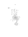
Фиг. 1 - пояснительный вид, схематично иллюстрирующий кривошипно-шатунный механизм с поршнем с двумя шатунами для двигателя внутреннего сгорания, в соответствии с изобретением.FIG. 1 is an explanatory view schematically illustrating a crank mechanism with a piston with two connecting rods for an internal combustion engine, in accordance with the invention.
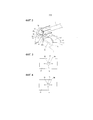
Фиг. 2 - пояснительный вид с увеличением, иллюстрирующий основную часть изобретения.FIG. 2 is an explanatory enlarged view illustrating the main part of the invention.
Фиг. 3 - пояснительный вид, иллюстрирующий развитую несущую поверхность коленчатого вала кривошипно-шатунного механизма с поршнем с двумя шатунами для двигателя внутреннего сгорания, в соответствии с изобретением.FIG. 3 is an explanatory view illustrating a developed bearing surface of a crankshaft of a crank mechanism with a piston with two connecting rods for an internal combustion engine, in accordance with the invention.
Фиг. 4 - пояснительный вид, иллюстрирующий развитую несущую поверхность коленчатого вала кривошипно-шатунного механизма с поршнем с двумя шатунами для двигателя внутреннего сгорания, в сравнительном примере.FIG. 4 is an explanatory view illustrating a developed bearing surface of a crankshaft of a crank mechanism with a piston with two connecting rods for an internal combustion engine, in a comparative example.
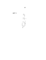
Фиг. 5 - другой увеличенный пояснительный вид, иллюстрирующий существенную часть изобретения.FIG. 5 is another enlarged explanatory view illustrating an essential part of the invention.
ОПИСАНИЕ ВАРИАНТОВ ОСУЩЕСТВЛЕНИЯ ИЗОБРЕТЕНИЯDESCRIPTION OF EMBODIMENTS OF THE INVENTION
Один вариант осуществления настоящего изобретения будет подробно описан далее со ссылкой на чертежи.One embodiment of the present invention will be described in detail below with reference to the drawings.
На фиг. 1 показан пояснительный вид, схематично иллюстрирующий общую конфигурацию кривошипно-шатунного механизма 1 с поршнем с двумя шатунами для двигателя внутреннего сгорания, в котором применяется изобретение, если смотреть в осевом направлении коленчатого вала.In FIG. 1 is an explanatory view schematically illustrating a general configuration of a crank mechanism 1 with a piston with two connecting rods for an internal combustion engine to which the invention is applied when viewed in the axial direction of the crankshaft.
Кривошипно-шатунный механизм 1 с поршнем с двумя шатунами, в основном, состоит из трех шатунов (описаны ниже), то есть нижнего шатуна 2, верхнего шатуна 3 и шатуна 4 управления. В представленном варианте осуществления кривошипно-шатунный механизм с поршнем с двумя шатунами выполнен, как механизм с переменной степенью сжатия, который изменяет положение верхней мертвой точки (ВМТ) поршня.The crank mechanism 1 with a piston with two connecting rods mainly consists of three connecting rods (described below), that is, the lower connecting
На коленчатом валу 5 сформировано множество частей 6 шейки и множество шатунных шеек 7, таким образом, что части 6 шейки установлены с возможностью вращения на соответствующих основных подшипниках блока 8 цилиндров. Шатунная шейка 7 смещена от части 6 шейки на заданную величину эксцентричности. Нижний шатун 2 установлен с возможностью вращения на шатунной шейке.A plurality of
С целью установки нижнего шатуна на шатунной шейке 7 нижний шатун 2 выполнен таким образом, что нижний шатун может быть разделен на два элемента, а именно, верхний и нижний разделенные половинчатые элементы. Таким образом, нижний шатун 2, в основном, состоит из пары разделенных элементов 10, 11 нижнего шатуна, которые разделены вертикально вдоль разделенной поверхности 9, которая проходит через центр шатунной шейки 7.In order to install the lower connecting rod on the connecting rod journal 7, the
Верхний шатун 3 соединен с возможностью вращения на стороне одного конца (то есть на верхнем конце) с поршнем 13 через поршневой палец 12. Часть 14 бобышки для пальца, которая находится на стороне другого конца (то есть на нижнем конце) верхнего шатуна, соединена с возможностью вращения с частью 16 бобышки для пальца на стороне одного конца нижнего шатуна 2 через первый соединительный палец 15. Поршень 13 выполняет возвратно-поступательные движения в цилиндре 17 блока 8 цилиндров.The upper connecting rod 3 is rotatably connected on the side of one end (i.e., on the upper end) to the
Что касается шатуна 4 управления, который ограничивает движение нижнего шатуна 2, нижний конец (то есть сторона одного конца шатуна управления) соединен через вал 18 управления с нижней секцией блока 8 цилиндров, составляющей часть основного корпуса двигателя. Часть 19 бобышки для пальца, соответствующая верхнему концу (то есть стороне другого конца шатуна управления), соединена с частью 21 бобышки для пальца на стороне другого конца нижнего шатуна 2 через второй соединительный палец 20. Вал 18 управления установлен с возможностью вращения на корпусе двигателя и выполнен таким образом, что он имеет часть 22 эксцентричного кулачка, геометрический центр которого расположен эксцентрично относительно центра вращения вала управления. Нижний конец (то есть сторона одного конца шатуна 4 управления) соединен с возможностью вращения с эксцентричным кулачком 22. Вращающимся участком вала 18 управления управляют посредством активатора управления степенью сжатия (не показан), который работает на основе сигнала управления от модуля управления двигателем (не показан).As for the
В описанном ранее кривошипно-шатунном механизме 1 с поршнем с двумя шатунами, когда вал 18 управления вращается под воздействием активатора управления степенью сжатия, положение центра части 22 эксцентричного кулачка, в частности относительное положение части эксцентричного кулачка относительно корпуса двигателя, изменяется. Поэтому положение, удерживаемое с возможностью качания (точка опоры качания) нижнего конца шатуна 4 управления, изменяется. Сразу же после изменения положения, поддерживаемого с возможностью качания шатуна 4 управления, изменяется рабочий ход поршня 13, и, таким образом, положение верхней мертвой точки (ВМТ) поршня 13 становится выше или ниже. Таким образом, можно изменять степень сжатия двигателя.In the previously described crank mechanism 1 with a piston with two connecting rods, when the
Кроме того, маслопроводный канал 31 шатунной шейки сформирован в шатунной шейке 7. Маслопроводный канал шатунной шейки 31 сформирован так, что он проходит радиально вверх внутри шатунной шейки 7, проходя через центр шатунной шейки, если смотреть в осевом направлении коленчатого вала. В варианте осуществления оба конца маслопроводного канала шатунной шейки выполнены так, что они открываются на внешней периферийной поверхности шатунной шейки 7. Смазочное масло, поступающее под давлением от масляного насоса (не показан), подают в маслопроводный канал 31 шатунной шейки через осевой маслопроводный канал 32, сформированный так, что он проходит вдоль осевого направления коленчатого вала 5.In addition, the
Часть 16 бобышки для пальца на стороне одного конца нижнего шатуна 2 предусмотрена на разделенном элементе 10 нижнего шатуна и сформирована с приданием формы вилки так, что она зажимает часть 14 бобышки для пальца, расположенную на стороне другого конца верхнего шатуна 3, таким образом, что участки в форме вилки располагаются напротив пары внешних боковых сторон части 14 бобышки для пальца. Первый соединительный палец 15 выполнен так, что он проходит с возможностью вращения через часть 14 бобышки для пальца верхнего шатуна 3 и фиксированно соединен с частью 16 бобышки для пальца на стороне одного конца нижнего шатуна 2, оба конца которого сформированы как секции в форме вилки, используя установку с прессовой посадкой. Удлиненная поверхность 33, обращенная к бобышке для пальца, предусмотрена между секциями в форме вилки части 16 бобышки для пальца на стороне одного конца таким образом, что удлиненная поверхность, обращенная к бобышке для пальца, обращена к внешней периферийной поверхности части 14 бобышки для пальца верхнего шатуна 3. Поверхность 33, обращенная к бобышке для пальца, выполнена с определенным контуром и сформирована с приданием ей изогнутой поверхности.The
Часть 21 бобышки для пальца на стороне другого конца нижнего шатуна 2 предусмотрена в разделенном элементе 11 нижнего шатуна и сформирована с приданием формы вилки таким образом, что она зажимает часть 19 бобышки для пальца, расположенную на стороне другого конца шатуна 4 управления таким образом, что выступы в виде вилки располагаются противоположно паре внешних боковых поверхностей сторон части 19 бобышки для пальца таким образом, что секции в виде вилки располагаются противоположно паре внешних боковых сторон части 19 бобышки для пальца. Второй соединительный палец 20 выполнен так, что он проходит с возможностью вращения насквозь через часть 19 бобышки для пальца шатуна 4 управления и фиксированно соединен с частью 21 бобышки для пальца стороны другого конца нижнего шатуна 2, оба конца которого сформированы как секции в форме вилки с использованием установки с прессовой посадкой. Удлиненная поверхность 34, обращенная к бобышке для пальца, предусмотрена между секциями в форме вилки части 21 бобышки для пальца на стороне другого конца таким образом, что удлиненная поверхность, обращенная к бобышке для пальца, обращена к внешней периферийной поверхности части 19 бобышки для пальца шатуна 4 управления. Поверхность 34, обращенная к бобышке для пальца, имеет контур и сформирована в виде изогнутой поверхности.The
Как показано на фиг. 2, в кривошипно-шатунном механизме с поршнем 1 с двумя шатунами в соответствии с вариантом осуществления маслопроводный канал 35 бобышки для пальца сформирован в части 14 бобышки для пальца, расположенной на стороне другого конца верхнего шатуна 3, тогда как маслопроводный канал 36 нижнего шатуна сформирован в разделенном элементе 10 нижнего шатуна.As shown in FIG. 2, in a crank mechanism with a piston 1 with two connecting rods according to an embodiment, the
Маслопроводный канал 35 бобышки для пальца сформирован в одной из внешних боковых сторон части 14 бобышки для пальца как поверхностная канавка таким образом, что отверстие 35a на стороне одного конца открывается к внутренней периферийной поверхности части 14 бобышки для пальца верхнего шатуна 3 и что отверстие 35b на стороне другого конца открывается к внешней периферийной поверхности части 14 бобышки для пальца верхнего шатуна 3. В частности, маслопроводный канал 35 бобышки для пальца может быть сформирован как сквозное отверстие, которое проходит насквозь через часть 14 бобышки для пальца.The
Маслопроводный канал 36 нижнего шатуна сформирован как сквозное отверстие, которое проходит насквозь через разделенный элемент 11 нижнего шатуна, и имеет отверстие 36a на стороне одного конца, выполненное так, что оно открывается к поверхности 33, обращенной к бобышке для пальца, и другое отверстие 36b на стороне другого конца, выполненное так, что оно открывается к несущей поверхности 37 шатунной шейки. Кроме того, маслопроводный канал 36 нижнего шатуна выполнен так, что он входит в сообщение по текучей среде с маслопроводным каналом 31 шатунной шейки под заданным углом коленчатого вала (например, в нижней мертвой точке) для выпуска струи смазочного масла через отверстие 36a на стороне одного конца.The
Кроме того, маслопроводный канал 36 нижнего шатуна сформирован так, что он направлен под упомянутым выше заданным углом коленчатого вала на определенную концевую кромку среди концевых кромок отверстия 35b на стороне другого конца маслопроводного канала 35 бобышки для пальца, сформированного в части 14 бобышки для пальца верхнего шатуна 3, определенная концевая кромка обращена в сторону направления перемещения части 14 бобышки для пальца. Другими словами, маслопроводный канал 36 нижнего шатуна сформирован так, что он направлен, под упомянутым выше заданным углом коленчатого вала, на определенную концевую кромку среди концевых кромок отверстия 35b на стороне другого конца маслопроводного канала 35 бобышки для пальца, сформированного в части 14 бобышки для пальца верхнего шатуна 3, причем определенная концевая кромка обращена к одной концевой стороне верхнего шатуна 3.In addition, the
Часть 14 бобышки для пальца, которая расположена на другой концевой стороне верхнего шатуна 3 и в которой сформирован маслопроводный канал 35 бобышки для пальца, перемещается в ходе вращательного движения, как обозначено стрелками на фиг. 2, по мере того, как поршень приближается к положению верхней мертвой точки из положения, соответствующего заданному углу коленчатого вала. Следовательно, установленный участок части бобышки для пальца на другой концевой стороне верхнего шатуна, на котором сформирован маслопроводный канал бобышки для пальца, движется в пределах области "S" распыления смазочного масла, которое заранее распыляют через отверстие 36a на стороне одного конца маслопроводного канала 36 нижнего шатуна, увеличивая, таким образом, прилежащий угол между верхним шатуном 3 и нижним шатуном 2. Поэтому даже когда двигатель внутреннего сгорания работает в диапазоне высокой скорости, смазочное масло в области "S" распыления может поступать из маслопроводного канала 35 бобышки для пальца и затем может быть подано на несущий участок части 14 бобышки для пальца верхнего шатуна 3.The
Таким образом, даже когда рабочий диапазон двигателя внутреннего сгорания представляет собой диапазон с высокой скоростью, можно более эффективно подавать смазочное масло на несущий участок части 14 бобышки для пальца верхнего шатуна 3 по сравнению с конфигурацией, когда смазочное масло распыляется из маслопроводного канала 36 нижнего шатуна в такие моменты времени, когда маслопроводный канал 35 бобышки для пальца расположен на продленной линии маслопроводного канала 36 нижнего шатуна.Thus, even when the operating range of the internal combustion engine is a high speed range, it is possible to more effectively supply lubricating oil to the bearing portion of the
Следовательно, возможно относительно повысить подачу смазочного масла на несущий участок части 14 бобышки для пальца, которая расположена на стороне другого конца верхнего шатуна 3, улучшая, таким образом, свойство противодействия заеданию части 14 бобышки для пальца верхнего шатуна 3.Therefore, it is possible to relatively increase the supply of lubricating oil to the bearing portion of the
Кроме того, маслопроводный канал 36 нижнего шатуна сформирован как сквозное отверстие, ортогональное стыковочным поверхностям пары разделенных элементов 10, 11 нижнего шатуна, которые разделены поверхностью 9. Поэтому в варианте осуществления, как показано на фиг. 3, отверстие 36b на стороне другого конца маслопроводного канала 36 нижнего шатуна, расположенное так, что оно открывается к несущей поверхности 37 шатунной шейки, сформировано в форме отверстия в виде паза, удлиненного вдоль направления внешней окружности несущей поверхности шатунной шейки. В частности, если предположить, что маслопроводный канал 36 нижнего шатуна сформирован вдоль радиального направления несущей поверхности 37 шатунной шейки, как показано на фиг. 4, отверстие 36b на стороне другого конца маслопроводного канала 36 нижнего шатуна выполненное так, что оно открывается к несущей поверхности 37 шатунной шейки, сформировано с приданием ему, по существу, полностью круглой формы. На фиг. 3 и 4 показаны пояснительные виды, каждый из которых схематично иллюстрирует развитую несущую поверхность 37 шатунной шейки нижнего шатуна 2. Направление слева направо каждой из фиг. 3 и 4 соответствует направлению внешней окружности несущей поверхности 37 шатунной шейки.Furthermore, the
В присутствии нагрузки, прикладываемой, как обозначено стрелками на фиг. 3 и 4, напряжения растяжения вдоль направления внешней окружности несущей поверхности шатунной шейки формируются на соответствующих несущих поверхностях 37 шатунной шейки. Поэтому вследствие таких напряжений растяжения отверстие 36b на стороне другого конца маслопроводного канала 36 нижнего шатуна расширяется вдоль направления внешней окружности несущей поверхности шатунной шейки. Однако в варианте осуществления отверстие 36b на стороне другого конца маслопроводного канала 36 нижнего шатуна сформировано в форме отверстия в виде паза, удлиненного вдоль направления внешней окружности несущей поверхности шатунной шейки. Таким образом, кривизна участков P1 и P2, расширяемых под действием напряжений растяжения вдоль направления внешней окружности несущей поверхности шатунной шейки, становится относительно малой.In the presence of a load applied as indicated by arrows in FIG. 3 and 4, tensile stresses along the outer circumference of the bearing surface of the connecting rod journal are formed on the respective bearing surfaces 37 of the connecting rod journal. Therefore, due to such tensile stresses, the
Поэтому по сравнению с конфигурацией, когда отверстие 36b на стороне другого конца маслопроводного канала 36 нижнего шатуна сформировано с приданием ему, по существу, полностью круглой формы, возможно эффективно устранить концентрацию напряжений, прикладываемых к отверстию 36b на стороне другого конца маслопроводного канала нижнего шатуна 36, уменьшая, таким образом, напряжения, образующиеся в отверстии 36b на стороне другого конца маслопроводного канала 36 нижнего шатуна. В целом становится возможным улучшить устойчивость к усталости нижнего шатуна 2.Therefore, compared with the configuration, when the
В частности, в варианте осуществления отверстие 36a на стороне одного конца маслопроводного канала 36 нижнего шатуна также сформировано в форме отверстия в виде паза. Более конкретно, отверстие 36a на стороне одного конца маслопроводного канала 36 нижнего шатуна сформировано с приданием формы отверстия в виде паза, удлиненного вдоль продольного направления поверхности 33, обращенной к бобышке для пальца. В присутствии входной нагрузки напряжения растяжения вдоль продольного направления поверхности, обращенной к бобышке для пальца, формируются на поверхности 33, обращенной к бобышке для пальца. Вследствие таких напряжений растяжения отверстие 36a на стороне одного конца маслопроводного канала 36 нижнего шатуна расширяется вдоль продольного направления поверхности 33, обращенной к бобышке для пальца. Однако отверстие 36a на стороне одного конца маслопроводного канала 36 нижнего шатуна сформировано в форме отверстия в виде паза, удлиненного вдоль продольного направления поверхности, обращенной к бобышке для пальца. Таким образом, кривизна участков, растягивающихся под действием напряжения растяжения вдоль продольного направления поверхности, обращенной к бобышке для пальца, становится относительно малой таким же образом, как и у отверстия 36b на стороне другого конца, как описано выше. Поэтому возможно эффективно уменьшить концентрацию напряжений, прикладываемых к отверстию 36a на стороне одного конца маслопроводного канала 36 нижнего шатуна, уменьшая, таким образом, напряжения, образующиеся в отверстии 36a на стороне одного конца маслопроводного канала 36 нижнего шатуна. В целом можно улучшить устойчивость к усталости нижнего шатуна 2.In particular, in the embodiment, the
Кроме того, маслопроводный канал 36 нижнего шатуна выполнен или расположен ортогонально разделенной поверхности 9. Это способствует механической обработке маслопроводного канала 36 нижнего шатуна на разделенной поверхности 9, которая используется как важное положение (опорное положение). По сравнению с конфигурацией, в которой маслопроводный канал 36 нижнего шатуна сформирован в радиальном направлении несущей поверхности 37 шейки шатуна, возможно уменьшить затраты на механическую обработку.In addition, the
Как показано на фиг. 1, маслопроводный канал 36 нижнего шатуна выполнен или расположен так, чтобы он был смещен от положения ввода входной нагрузки F1, прикладываемой к нижнему шатуну 2, когда максимальная нагрузка при сгорании действует на поршень. Следовательно, возможно улучшить устойчивость к усталости нижнего шатуна 2.As shown in FIG. 1, the
Кроме того, как показано на фиг. 5, часть 14 бобышки для пальца, которая расположена на стороне другого конца верхнего шатуна 3, сформирована и выполнена суживающейся таким образом, что толщина корня (сторона лежащего в основе конца) становится относительно тоньше, и, таким образом, площадь несущей корневой части (сторона лежащего в основе конца) в части 14 бобышки для пальца относительно уменьшается. Следовательно, когда часть 14 бобышки для пальца проходит через область “S” распыления, смазочное масло может поступать на несущий участок части 14 бобышки для пальца верхнего шатуна 3 из корневой части в части 14 бобышки для пальца верхнего шатуна 3, а также через маслопроводный канал 35 бобышки для пальца. Таким образом, становится возможным дополнительно улучшить свойство противодействия заеданию части 14 бобышки для пальца верхнего шатуна 3.Furthermore, as shown in FIG. 5,
В частности, механизм описанного выше варианта осуществления выполнен таким образом, что смазочное масло поступает через маслопроводный канал 31 шатунной шейки к соединительной части нижнего шатуна 2 и верхнего шатуна 3. С учетом этого изобретение может применяться в такой конфигурации, когда смазочное масло поступает из маслопроводного канала 31 шатунной шейки к соединительной части нижнего шатуна 2 и шатуна 4 управления. Например, маслопроводный канал бобышки для пальца может быть сформирован в части 19 бобышки для пальца, которая расположена на стороне другого конца шатуна 4 управления. Кроме того, другой маслопроводный канал нижнего шатуна может быть сформирован в части 21 бобышки для пальца на стороне другого конца нижнего шатуна 2 таким образом, что один конец открывается к поверхности 34, обращенной к бобышке для пальца, предусмотренной между секциями в форме вилки части 21 бобышки для пальца на стороне другого конца, и другой конец открывается к несущей поверхности 37 шатунной шейки. В этом случае другой маслопроводный канал нижнего шатуна выполнен так, что он входит в сообщение по текучей среде с маслопроводным каналом 31 шатунной шейки под установленным углом коленчатого вала. Кроме того, другой маслопроводный канал нижнего шатуна сформирован так, что он направлен, под установленным упомянутым выше заданным углом коленчатого вала, на определенную концевую кромку из двух кромок отверстия на стороне другого конца маслопроводного канала бобышки для пальца, сформированного в части 19 бобышки для пальца шатуна 4 управления, определенная концевая кромка обращена к стороне направления перемещения части 19 бобышки для пальца. Однако в том, что касается магнитуды входной нагрузки, воздействующей на нижний шатун 2, входная нагрузка, прикладываемая к соединительной части, соединенной с верхним шатуном 3, относительно больше, чем прикладывается к соединительной части, соединенной с шатуном 4 управления. Поэтому маслопроводный канал нижнего шатуна, сформированный на стороне верхнего шатуна, является относительно большим, чем другой маслопроводный канал нижнего шатуна, с эффектом уменьшения концентрации напряжений, получаемых в результате формирования отверстия маслопроводного канала нижнего шатуна в форме отверстия в виде паза.In particular, the mechanism of the embodiment described above is such that the lubricating oil enters through the
Кроме того, изобретение применимо к кривошипно-шатунному механизму с поршнем с двумя шатунами, так что кривошипно-шатунный механизм 1 с поршнем с двумя шатунами не выполнен как механизм с переменной степенью сжатия.In addition, the invention is applicable to a crank mechanism with a piston with two connecting rods, so that the crank mechanism 1 with a piston with two connecting rods is not made as a mechanism with a variable compression ratio.
Claims (17)
Applications Claiming Priority (3)
| Application Number | Priority Date | Filing Date | Title |
|---|---|---|---|
| JP2013171808 | 2013-08-22 | ||
| JP2013-171808 | 2013-08-22 | ||
| PCT/JP2014/070018 WO2015025683A1 (en) | 2013-08-22 | 2014-07-30 | Double-link piston crank mechanism for internal combustion engine |
Publications (1)
| Publication Number | Publication Date |
|---|---|
| RU2618149C1 true RU2618149C1 (en) | 2017-05-02 |
Family
ID=52483464
Family Applications (1)
| Application Number | Title | Priority Date | Filing Date |
|---|---|---|---|
| RU2016109600A RU2618149C1 (en) | 2013-08-22 | 2014-07-30 | Crank mechanism with piston and two rods for internal combustion engine |
Country Status (8)
| Country | Link |
|---|---|
| US (1) | US9856907B2 (en) |
| EP (1) | EP3037642B1 (en) |
| JP (1) | JP5971422B2 (en) |
| CN (1) | CN105579684B (en) |
| BR (1) | BR112016003572B1 (en) |
| MX (1) | MX346228B (en) |
| RU (1) | RU2618149C1 (en) |
| WO (1) | WO2015025683A1 (en) |
Families Citing this family (6)
| Publication number | Priority date | Publication date | Assignee | Title |
|---|---|---|---|---|
| MX367001B (en) | 2013-08-27 | 2019-08-02 | Nissan Motor | Multi-link piston-crank mechanism for internal combustion engine. |
| JP6380681B2 (en) | 2015-09-04 | 2018-08-29 | 日産自動車株式会社 | Lubricating structure and lubricating method for upper pin in piston crank mechanism of internal combustion engine |
| JP6658260B2 (en) * | 2016-04-25 | 2020-03-04 | 日産自動車株式会社 | Lubrication structure of double-link piston-crank mechanism |
| CN112189085B (en) * | 2018-06-07 | 2022-06-24 | 日产自动车株式会社 | Multi-link piston crank mechanism of internal combustion engine |
| CA3131953A1 (en) | 2019-03-01 | 2020-09-10 | Merrimack Pharmaceuticals, Inc. | Anti-tnfr2 antibodies and uses thereof |
| JP7338796B2 (en) | 2020-09-15 | 2023-09-05 | 日産自動車株式会社 | Internal combustion engine lower link |
Citations (5)
| Publication number | Priority date | Publication date | Assignee | Title |
|---|---|---|---|---|
| SU1353895A1 (en) * | 1986-04-15 | 1987-11-23 | Производственное Объединение "Турбомоторный Завод" Им.К.Е.Ворошилова | Crank mechanism for internal combustion engine with fuel pump correcting regulator |
| JPH08200150A (en) * | 1995-01-20 | 1996-08-06 | Toyota Motor Corp | Piston for internal combustion engine |
| RU2166653C2 (en) * | 1997-12-24 | 2001-05-10 | Акционерное общество открытого типа - Холдинговая компания "Барнаултрансмаш" | Internal combustion engine |
| JP2001200711A (en) * | 2000-01-17 | 2001-07-27 | Honda Motor Co Ltd | Piston oil-cooling device for engine |
| JP2010185329A (en) * | 2009-02-12 | 2010-08-26 | Nissan Motor Co Ltd | Multi-link type piston crank mechanism of internal combustion engine |
Family Cites Families (12)
| Publication number | Priority date | Publication date | Assignee | Title |
|---|---|---|---|---|
| JPS61157121U (en) * | 1985-03-20 | 1986-09-29 | ||
| JPS63174541U (en) * | 1986-12-03 | 1988-11-11 | ||
| JP2546127Y2 (en) * | 1990-08-29 | 1997-08-27 | 株式会社日本自動車部品総合研究所 | Cylinder lubrication device |
| JPH04105911U (en) * | 1991-02-25 | 1992-09-11 | 富士重工業株式会社 | Lubricating oil supply device for sliding bearings |
| JPH08200152A (en) * | 1995-01-23 | 1996-08-06 | Toyota Motor Corp | Piston device for internal combustion engine |
| JP4096700B2 (en) * | 2002-11-05 | 2008-06-04 | 日産自動車株式会社 | Variable compression ratio device for internal combustion engine |
| KR100528207B1 (en) * | 2003-10-01 | 2005-11-15 | 현대자동차주식회사 | Piston pin combination structure of piston |
| JP4646879B2 (en) * | 2006-09-08 | 2011-03-09 | 本田技研工業株式会社 | Variable stroke characteristics engine |
| JP5330851B2 (en) * | 2009-02-12 | 2013-10-30 | ソフィサ | Device for mechanically positioning and reading the setpoint of the adjustable valve |
| JP5251576B2 (en) * | 2009-02-12 | 2013-07-31 | 日産自動車株式会社 | Double link piston crank mechanism for internal combustion engine |
| JP2010203270A (en) * | 2009-03-02 | 2010-09-16 | Nissan Motor Co Ltd | Lubricating device of double-link type internal combustion engine |
| EP2463498B1 (en) * | 2009-07-17 | 2016-07-20 | Nissan Motor Co., Ltd. | Multi-link piston-crank mechanism |
-
2014
- 2014-07-30 EP EP14837631.2A patent/EP3037642B1/en active Active
- 2014-07-30 JP JP2015532786A patent/JP5971422B2/en active Active
- 2014-07-30 BR BR112016003572-0A patent/BR112016003572B1/en active IP Right Grant
- 2014-07-30 CN CN201480051873.3A patent/CN105579684B/en active Active
- 2014-07-30 RU RU2016109600A patent/RU2618149C1/en active
- 2014-07-30 US US14/913,054 patent/US9856907B2/en active Active
- 2014-07-30 WO PCT/JP2014/070018 patent/WO2015025683A1/en active Application Filing
- 2014-07-30 MX MX2016002207A patent/MX346228B/en active IP Right Grant
Patent Citations (5)
| Publication number | Priority date | Publication date | Assignee | Title |
|---|---|---|---|---|
| SU1353895A1 (en) * | 1986-04-15 | 1987-11-23 | Производственное Объединение "Турбомоторный Завод" Им.К.Е.Ворошилова | Crank mechanism for internal combustion engine with fuel pump correcting regulator |
| JPH08200150A (en) * | 1995-01-20 | 1996-08-06 | Toyota Motor Corp | Piston for internal combustion engine |
| RU2166653C2 (en) * | 1997-12-24 | 2001-05-10 | Акционерное общество открытого типа - Холдинговая компания "Барнаултрансмаш" | Internal combustion engine |
| JP2001200711A (en) * | 2000-01-17 | 2001-07-27 | Honda Motor Co Ltd | Piston oil-cooling device for engine |
| JP2010185329A (en) * | 2009-02-12 | 2010-08-26 | Nissan Motor Co Ltd | Multi-link type piston crank mechanism of internal combustion engine |
Also Published As
| Publication number | Publication date |
|---|---|
| JP5971422B2 (en) | 2016-08-17 |
| BR112016003572A2 (en) | 2017-08-01 |
| JPWO2015025683A1 (en) | 2017-03-02 |
| EP3037642A4 (en) | 2016-08-24 |
| CN105579684B (en) | 2017-06-13 |
| BR112016003572B1 (en) | 2021-09-14 |
| MX2016002207A (en) | 2016-06-06 |
| US9856907B2 (en) | 2018-01-02 |
| CN105579684A (en) | 2016-05-11 |
| EP3037642A1 (en) | 2016-06-29 |
| EP3037642B1 (en) | 2018-01-17 |
| MX346228B (en) | 2017-03-13 |
| US20160201717A1 (en) | 2016-07-14 |
| WO2015025683A1 (en) | 2015-02-26 |
Similar Documents
| Publication | Publication Date | Title |
|---|---|---|
| RU2618149C1 (en) | Crank mechanism with piston and two rods for internal combustion engine | |
| JP5298911B2 (en) | Double link piston crank mechanism for internal combustion engine | |
| JP6183560B2 (en) | Internal combustion engine | |
| JP5304187B2 (en) | Double link piston crank mechanism for internal combustion engine | |
| JP6380681B2 (en) | Lubricating structure and lubricating method for upper pin in piston crank mechanism of internal combustion engine | |
| JP5983877B2 (en) | Bearing structure of a multi-link piston crank mechanism of an internal combustion engine | |
| WO2016157575A1 (en) | Connecting rod and cross-head type engine provided with same | |
| US8826882B2 (en) | Lubricating structure of multi-link piston-crank mechanism for internal combustion engine | |
| JP6132057B2 (en) | Lubrication structure of a multi-link piston-crank mechanism of an internal combustion engine | |
| JP5251576B2 (en) | Double link piston crank mechanism for internal combustion engine | |
| JP5810675B2 (en) | Double link type piston-crank mechanism for internal combustion engine | |
| WO2015025684A1 (en) | Internal combustion engine | |
| JP2010185396A (en) | Lubricating device for reciprocating type variable compression ratio engine | |
| JP6141535B2 (en) | Coupling link for multi-link crank mechanism and multi-link crank mechanism | |
| US20090101004A1 (en) | Two part piston for an internal combustion engine | |
| WO2017202777A1 (en) | Connecting rod for an internal combustion engine with adjustable compression ratio | |
| JP2019148169A (en) | Double-link type piston crank mechanism of internal combustion engine | |
| JP7107003B2 (en) | Multi-link piston crank mechanism for internal combustion engine | |
| CN201487167U (en) | Circular sliding block and crank circular sliding block mechanism and mechanical equipment thereof | |
| JP2010203270A (en) | Lubricating device of double-link type internal combustion engine | |
| RU2626613C2 (en) | Ice with variable compression ratio | |
| KR101799744B1 (en) | Link-type piston crank mechanism of internal combustion engine | |
| JP5321148B2 (en) | Double link variable compression ratio internal combustion engine | |
| JP2018054041A (en) | Bush of connecting rod |