JP5971422B2 - Double link piston crank mechanism for internal combustion engine - Google Patents
Double link piston crank mechanism for internal combustion engine Download PDFInfo
- Publication number
- JP5971422B2 JP5971422B2 JP2015532786A JP2015532786A JP5971422B2 JP 5971422 B2 JP5971422 B2 JP 5971422B2 JP 2015532786 A JP2015532786 A JP 2015532786A JP 2015532786 A JP2015532786 A JP 2015532786A JP 5971422 B2 JP5971422 B2 JP 5971422B2
- Authority
- JP
- Japan
- Prior art keywords
- link
- oil passage
- pin boss
- pin
- lower link
- Prior art date
- Legal status (The legal status is an assumption and is not a legal conclusion. Google has not performed a legal analysis and makes no representation as to the accuracy of the status listed.)
- Active
Links
Images


Classifications
-
- F—MECHANICAL ENGINEERING; LIGHTING; HEATING; WEAPONS; BLASTING
- F16—ENGINEERING ELEMENTS AND UNITS; GENERAL MEASURES FOR PRODUCING AND MAINTAINING EFFECTIVE FUNCTIONING OF MACHINES OR INSTALLATIONS; THERMAL INSULATION IN GENERAL
- F16C—SHAFTS; FLEXIBLE SHAFTS; ELEMENTS OR CRANKSHAFT MECHANISMS; ROTARY BODIES OTHER THAN GEARING ELEMENTS; BEARINGS
- F16C7/00—Connecting-rods or like links pivoted at both ends; Construction of connecting-rod heads
- F16C7/02—Constructions of connecting-rods with constant length
- F16C7/023—Constructions of connecting-rods with constant length for piston engines, pumps or the like
-
- F—MECHANICAL ENGINEERING; LIGHTING; HEATING; WEAPONS; BLASTING
- F01—MACHINES OR ENGINES IN GENERAL; ENGINE PLANTS IN GENERAL; STEAM ENGINES
- F01M—LUBRICATING OF MACHINES OR ENGINES IN GENERAL; LUBRICATING INTERNAL COMBUSTION ENGINES; CRANKCASE VENTILATING
- F01M11/00—Component parts, details or accessories, not provided for in, or of interest apart from, groups F01M1/00 - F01M9/00
- F01M11/02—Arrangements of lubricant conduits
-
- F—MECHANICAL ENGINEERING; LIGHTING; HEATING; WEAPONS; BLASTING
- F02—COMBUSTION ENGINES; HOT-GAS OR COMBUSTION-PRODUCT ENGINE PLANTS
- F02B—INTERNAL-COMBUSTION PISTON ENGINES; COMBUSTION ENGINES IN GENERAL
- F02B75/00—Other engines
- F02B75/04—Engines with variable distances between pistons at top dead-centre positions and cylinder heads
- F02B75/045—Engines with variable distances between pistons at top dead-centre positions and cylinder heads by means of a variable connecting rod length
-
- F—MECHANICAL ENGINEERING; LIGHTING; HEATING; WEAPONS; BLASTING
- F16—ENGINEERING ELEMENTS AND UNITS; GENERAL MEASURES FOR PRODUCING AND MAINTAINING EFFECTIVE FUNCTIONING OF MACHINES OR INSTALLATIONS; THERMAL INSULATION IN GENERAL
- F16C—SHAFTS; FLEXIBLE SHAFTS; ELEMENTS OR CRANKSHAFT MECHANISMS; ROTARY BODIES OTHER THAN GEARING ELEMENTS; BEARINGS
- F16C3/00—Shafts; Axles; Cranks; Eccentrics
- F16C3/04—Crankshafts, eccentric-shafts; Cranks, eccentrics
- F16C3/06—Crankshafts
- F16C3/14—Features relating to lubrication
-
- F—MECHANICAL ENGINEERING; LIGHTING; HEATING; WEAPONS; BLASTING
- F01—MACHINES OR ENGINES IN GENERAL; ENGINE PLANTS IN GENERAL; STEAM ENGINES
- F01M—LUBRICATING OF MACHINES OR ENGINES IN GENERAL; LUBRICATING INTERNAL COMBUSTION ENGINES; CRANKCASE VENTILATING
- F01M1/00—Pressure lubrication
- F01M1/06—Lubricating systems characterised by the provision therein of crankshafts or connecting rods with lubricant passageways, e.g. bores
- F01M2001/062—Crankshaft with passageways
-
- F—MECHANICAL ENGINEERING; LIGHTING; HEATING; WEAPONS; BLASTING
- F01—MACHINES OR ENGINES IN GENERAL; ENGINE PLANTS IN GENERAL; STEAM ENGINES
- F01M—LUBRICATING OF MACHINES OR ENGINES IN GENERAL; LUBRICATING INTERNAL COMBUSTION ENGINES; CRANKCASE VENTILATING
- F01M11/00—Component parts, details or accessories, not provided for in, or of interest apart from, groups F01M1/00 - F01M9/00
- F01M11/02—Arrangements of lubricant conduits
- F01M2011/027—Arrangements of lubricant conduits for lubricating connecting rod bearings
-
- F—MECHANICAL ENGINEERING; LIGHTING; HEATING; WEAPONS; BLASTING
- F02—COMBUSTION ENGINES; HOT-GAS OR COMBUSTION-PRODUCT ENGINE PLANTS
- F02B—INTERNAL-COMBUSTION PISTON ENGINES; COMBUSTION ENGINES IN GENERAL
- F02B41/00—Engines characterised by special means for improving conversion of heat or pressure energy into mechanical power
- F02B41/02—Engines with prolonged expansion
- F02B41/04—Engines with prolonged expansion in main cylinders
-
- F—MECHANICAL ENGINEERING; LIGHTING; HEATING; WEAPONS; BLASTING
- F02—COMBUSTION ENGINES; HOT-GAS OR COMBUSTION-PRODUCT ENGINE PLANTS
- F02B—INTERNAL-COMBUSTION PISTON ENGINES; COMBUSTION ENGINES IN GENERAL
- F02B75/00—Other engines
- F02B75/04—Engines with variable distances between pistons at top dead-centre positions and cylinder heads
-
- F—MECHANICAL ENGINEERING; LIGHTING; HEATING; WEAPONS; BLASTING
- F16—ENGINEERING ELEMENTS AND UNITS; GENERAL MEASURES FOR PRODUCING AND MAINTAINING EFFECTIVE FUNCTIONING OF MACHINES OR INSTALLATIONS; THERMAL INSULATION IN GENERAL
- F16C—SHAFTS; FLEXIBLE SHAFTS; ELEMENTS OR CRANKSHAFT MECHANISMS; ROTARY BODIES OTHER THAN GEARING ELEMENTS; BEARINGS
- F16C3/00—Shafts; Axles; Cranks; Eccentrics
- F16C3/04—Crankshafts, eccentric-shafts; Cranks, eccentrics
- F16C3/06—Crankshafts
- F16C3/16—Features relating to cooling
-
- F—MECHANICAL ENGINEERING; LIGHTING; HEATING; WEAPONS; BLASTING
- F16—ENGINEERING ELEMENTS AND UNITS; GENERAL MEASURES FOR PRODUCING AND MAINTAINING EFFECTIVE FUNCTIONING OF MACHINES OR INSTALLATIONS; THERMAL INSULATION IN GENERAL
- F16C—SHAFTS; FLEXIBLE SHAFTS; ELEMENTS OR CRANKSHAFT MECHANISMS; ROTARY BODIES OTHER THAN GEARING ELEMENTS; BEARINGS
- F16C3/00—Shafts; Axles; Cranks; Eccentrics
- F16C3/04—Crankshafts, eccentric-shafts; Cranks, eccentrics
- F16C3/18—Eccentric-shafts
-
- F—MECHANICAL ENGINEERING; LIGHTING; HEATING; WEAPONS; BLASTING
- F16—ENGINEERING ELEMENTS AND UNITS; GENERAL MEASURES FOR PRODUCING AND MAINTAINING EFFECTIVE FUNCTIONING OF MACHINES OR INSTALLATIONS; THERMAL INSULATION IN GENERAL
- F16J—PISTONS; CYLINDERS; SEALINGS
- F16J1/00—Pistons; Trunk pistons; Plungers
- F16J1/10—Connection to driving members
- F16J1/14—Connection to driving members with connecting-rods, i.e. pivotal connections
Description
本発明は、内燃機関の複リンク式ピストンクランク機構に関する。 The present invention relates to a multi-link type piston crank mechanism for an internal combustion engine.
ピストンにピストンピンを介して一端が連結されたアッパリンクと、このアッパリンクの他端にアッパピンを介して連結され、かつクランクシャフトのクランクピンに連結されたロアリンクと、一端が機関本体側に揺動可能に支持され、かつ他端が上記ロアリンクにコントロールピンを介して連結されたコントロールリンクと、を備えてなる複リンク式ピストンクランク機構が従来から知られている。
An upper link having one end connected to the piston via a piston pin, a lower link connected to the other end of the upper link via an upper pin, and connected to the crank pin of the crankshaft, and one end on the
このようなロアリンクには、ピストンが受けた大きな燃焼圧力が、ピストンピン、アッパリンク、アッパピンを介してアッパピン軸受部から入力される。それと同時に、この荷重とつりあうように、クランクピン軸受部やコントロールピン軸受部にも荷重が発生する。従って、これらの軸受部の面圧は、一般的な単リンク式のレシプロエンジンに比べて厳しいものとなり、摩耗や焼き付きを防ぐために、十分な潤滑状態を維持することが求められる。 A large combustion pressure received by the piston is input to the lower link from the upper pin bearing portion via the piston pin, the upper link, and the upper pin. At the same time, a load is also generated in the crank pin bearing portion and the control pin bearing portion so as to balance this load. Accordingly, the surface pressure of these bearing portions becomes stricter than that of a general single link type reciprocating engine, and it is required to maintain a sufficient lubrication state in order to prevent wear and seizure.
例えば、特許文献1には、クランクシャフト内部に形成された油路と、クランクピンの内部に形成されたクランクピン油路と、ロアリンクに形成されたロアリンク油路と、アッパピンが回転可能に嵌合するアッパリンクのピンボス部に形成され、クランクシャフト軸方向視でロアリンク油路の延長線上に位置するピンボス油路と、を有し、所定クランク角のときに、クランクピン油路とロアリンク油路とが連通し、ロアリンク油路から噴出した潤滑油の一部がピンボス油路を介してアッパピン軸受部に供給されるように構成された複リンク式のピストンクランク機構が開示されている。 For example, in Patent Document 1, an oil passage formed inside a crankshaft, a crankpin oil passage formed inside a crankpin, a lower link oil passage formed on a lower link, and an upper pin are rotatable. A pin boss oil passage formed on a pin boss portion of the upper link to be fitted and positioned on an extension line of the lower link oil passage as viewed in the crankshaft axial direction, and at a predetermined crank angle, the crank pin oil passage and the lower A multi-link type piston crank mechanism is disclosed that is configured to communicate with a link oil passage and to supply a part of lubricating oil ejected from the lower link oil passage to an upper pin bearing portion via a pin boss oil passage. Yes.
しかしながら、ピンボス油路に対してロアリンク油路が適切な位置に設定されていないと、潤滑油の供給不足によりアッパピン軸受部の耐焼き付き性が低下することになる。例えば、内燃機関の運転領域が高回転領域のときには、慣性力によりロアリンク油路の開口の向きに潤滑油が飛び出しにくく、クランクシャフト軸方向視で、ロアリンク油路の延長線上にピンボス油路が位置するような構成では、必ずしも十分な潤滑油をピンボス油路に供給できない可能性がある。 However, if the lower link oil passage is not set at an appropriate position with respect to the pin boss oil passage, the seizure resistance of the upper pin bearing portion is lowered due to insufficient supply of the lubricating oil. For example, when the operating region of the internal combustion engine is a high rotation region, the lubricating oil is difficult to jump out in the direction of the opening of the lower link oil passage due to the inertia force, and the pin boss oil passage is on the extension line of the lower link oil passage as viewed from the crankshaft axial direction. In such a configuration, sufficient lubricating oil may not necessarily be supplied to the pin boss oil passage.
本発明の複リンク式ピストンクランク機構は、所定クランク角のときにクランクピン油路とロアリンク油路とが連通し、該ロアリンク油路の一端側開口から潤滑油が噴出するものであって、ロアリンク油路の一端側開口は、上記所定クランク角のときに、クランクシャフト軸方向視で、ピンボス油路の他端側開口の端縁うち、当該ピンボス油路が形成されたピンボス部の進行方向側の端縁を指向するよう形成されていることを特徴としている。 The multi-link type piston crank mechanism according to the present invention is such that the crank pin oil passage and the lower link oil passage communicate with each other at a predetermined crank angle, and lubricating oil is ejected from one end side opening of the lower link oil passage. The lower link oil passage has an opening on one end side of the pin boss portion on which the pin boss oil passage is formed out of the edge of the other end opening of the pin boss oil passage as viewed in the crankshaft axial direction at the predetermined crank angle. It is characterized by being formed so as to be directed to the edge on the traveling direction side.
これによって、ピンボス油路が形成されたピンボス部は、所定クランク角直後のタイミングでロアリンク油路の一端側開口から予め噴射された潤滑油の噴霧領域に移動することなる。 As a result, the pin boss portion in which the pin boss oil passage is formed moves to the spray region of the lubricant injected in advance from the one end side opening of the lower link oil passage at a timing immediately after the predetermined crank angle.
本発明によれば、内燃機関が高回転領域であっても、ピンボス部がロアリンク油路の一端側開口から予め噴射された潤滑油の噴霧領域を通過する際に、噴霧領域内の潤滑油をピンボス油路等から取り込んで、ピンボス部の軸受け部分に供給することができる。そのため、ピンボス部の軸受け部分に供給される潤滑油を相対的に増加させることが可能となり、ピンボス部における耐焼き付き性を向上させることができる。 According to the present invention, even when the internal combustion engine is in the high speed region, the lubricating oil in the spray region is generated when the pin boss portion passes through the spray region of the lubricant oil injected in advance from the one end side opening of the lower link oil passage. Can be taken in from the pin boss oil passage or the like and supplied to the bearing portion of the pin boss portion. Therefore, it is possible to relatively increase the lubricating oil supplied to the bearing portion of the pin boss portion, and to improve the seizure resistance in the pin boss portion.
以下、本発明の一実施例を図面に基づいて詳細に説明する。 Hereinafter, an embodiment of the present invention will be described in detail with reference to the drawings.
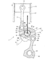
図1は、本発明が適用された内燃機関の複リンク式ピストンクランク機構1のクランクシャフト軸方向から見た概略構成を模式的に示した説明図である。 FIG. 1 is an explanatory view schematically showing a schematic configuration of a multi-link type piston crank mechanism 1 of an internal combustion engine to which the present invention is applied viewed from the crankshaft axial direction.
この複リンク式ピストンクランク機構1は、後述する3つのリンク(ロアリンク2、アッパリンク3、コントロールリンク4)を主体とするものであり、本実施例ではピストン上死点位置を変更可能な可変圧縮比機構となっている。
This multi-link type piston crank mechanism 1 mainly includes three links (
クランクシャフト5は、複数のジャーナル部6とクランクピン7とを備えており、シリンダブロック8の主軸受に、ジャーナル部6が回転可能に支持されている。クランクピン7は、ジャーナル部6から所定量偏心しており、ここにロアリンク2が回転可能に取り付けられている。
The
ロアリンク2は、クランクピン7への組み付けのために上下の2部材に分割可能に構成されている。すなわち、ロアリンク2は、クランクピン7中心を通る分割面9に沿って上下に分割された一対のロアリンク分割部材10、11から大略構成されている。
The
アッパリンク3は、一端側となる上端がピストンピン12によりピストン13に回転可能に取り付けられ、他端側となる下端のピンボス部14が第1連結ピン15によりロアリンク2の一端側ピンボス部16に回動可能に連結されている。ピストン13は、シリンダブロック8のシリンダ17内を往復動する。
The
ロアリンク2の運動を制限するコントロールリンク4は、一端側となる下端が制御軸18を介して機関本体の一部となるシリンダブロック8の下部に回転可能に連結され、他端側となる上端のピンボス部19が第2連結ピン20によりロアリンク2の他端側ピンボス部21に回転可能に連結されている。制御軸18は、回転可能に機関本体に支持されているとともに、その回転中心から偏心している偏心カム部22を有している。偏心カム部22には、コントロールリンク4の一端側となる下端が回転可能に連結されている。制御軸18は、エンジンコントロールユニット(図示せず)からの制御信号に基づいて作動する圧縮比制御用のアクチュエータ(図示せず)によって回動位置が制御されている。
The control link 4 that restricts the movement of the
このような複リンク式ピストンクランク機構1においては、制御軸18が、圧縮比制御用のアクチュエータによって回動されると、偏心カム部22の中心位置、特に、機関本体に対する相対位置が変化する。これにより、コントロールリンク4の下端の揺動支持位置が変化する。そして、コントロールリンク4の揺動支持位置が変化すると、ピストン13の行程が変化し、ピストン上死点(TDC)におけるピストン13の位置が高くなったり低くなったりする。これにより、機関圧縮比を変えることが可能となる。
In such a multi-link type piston crank mechanism 1, when the
また、クランクピン7には、クランクピン油路31が形成されている。クランクピン油路31は、クランクシャフト軸方向視で、クランクピン中心を通り、クランクピン7内部を径方向に直線状に延在するものであり、本実施例では、その両端が、それぞれクランクピン7の外周面に開口している。このクランクピン油路31には、クランクシャフト5の軸方向に沿って延びる軸方向油路32を経由して、図示せぬオイルポンプにより加圧された潤滑油が供給されている。
A
ロアリンク2の一端側ピンボス部16は、ロアリンク分割部材10に設けられ、アッパリンク3の他端側に位置するピンボス部14を挟み込むように二股状に形成され、ピンボス部14の一対の外側面と対向している。第1連結ピン15は、アッパリンク3のピンボス部14を回転可能に貫通し、その両端が二股状となったロアリンク2の一端側ピンボス部16に圧入により固定される。この一端側ピンボス部16の間には、アッパリンク3のピンボス部14の外周面に対向する細長いピンボス対向面33が設けられている。このピンボス対向面33は、曲面となるよう形成されている。
The one end side
ロアリンク2の他端側ピンボス部21は、ロアリンク分割部材11に設けられ、コントロールリンク4の他端側に位置するピンボス部19を挟み込むように二股状に形成されピンボス部19の一対の外側面と対向している。第2連結ピン20は、コントロールリンク4のピンボス部19を回転可能に貫通し、その両端が二股状となったロアリンク2の他端側ピンボス部21に圧入により固定される。この他端側ピンボス部21の間には、コントロールリンク4のピンボス部19の外周面に対向する細長いピンボス対向面34が設けられている。このピンボス対向面34は、曲面となるよう形成されている。
The other end side
そして、本実施例の複リンク式ピストンクランク機構1においては、図2に示すように、アッパリンク3の他端側に位置するピンボス部14にピンボス油路35が形成され、ロアリンク分割部材10にロアリンク油路36が形成されている。
In the multi-link piston crank mechanism 1 of the present embodiment, as shown in FIG. 2, a pin
ピンボス油路35は、ピンボス部14の一方の外側面に形成された溝であり、一端側開口35aがアッパリンク3のピンボス部14の内周面に開口し、他端側開口35bがアッパリンク3のピンボス部14の外周面に開口している。なお、ピンボス油路35を、ピンボス部14を貫通する貫通穴とすることも可能である。
The pin
ロアリンク油路36は、ロアリンク分割部材10を貫通する貫通穴であり、ピンボス対向面33に開口する一端側開口36aと、クランクピン軸受面37に開口する他端側開口36bと、を有している。また、ロアリンク油路36は、所定のクランク角(例えば下死点)のときに、クランクピン油路31と連通し、その一端側開口36aから潤滑油が噴出するよう形成されている。
The lower
さらに、このロアリンク油路36は、上記所定のクランク角のときに、アッパリンク3のピンボス部14に形成されたピンボス油路35の他端側開口35bの端縁のうち、ピンボス部14の進行方向側の端縁を指向するよう形成されている。換言すれば、ロアリンク油路36は、上記所定のクランク角のときに、アッパリンク3のピンボス部14に形成されたピンボス油路35の他端側開口35bの端縁のうち、アッパリンク3一端側の端縁を指向するよう形成されている。
Further, the lower
ピンボス油路35が形成されたアッパリンク3の他端側のピンボス部14は、上記所定クランク角における位置からピストン位置が上死点に向かうにつれて、図2中の矢示する方向に回転しつつ移動し、アッパリンク3とロアリンク2との挟角を大きくしながら、ロアリンク油路36の一端側開口36aから予め噴射された潤滑油の噴霧領域Sに移動することなる。そのため、内燃機関が高回転領域であっても、アッパリンク3のピンボス部14の軸受け部分には、噴霧領域S内にある潤滑油をピンボス油路35から取り込んで供給することができる。
The
つまり、内燃機関の運転領域が高回転領域であっても、ピンボス油路35がロアリンク油路36の延長線上に位置するようなタイミングでロアリンク油路36から潤滑油を噴射する場合に比べ、より効率良く潤滑油をアッパリンク3のピンボス部14の軸受け部分に供給することが可能となる。
In other words, even when the operating region of the internal combustion engine is a high rotation region, compared with the case where the lubricating oil is injected from the lower
これによって、アッパリンク3の他端側に位置するピンボス部14の軸受け部分に供給される潤滑油を相対的に増加させることが可能となり、アッパリンク3のピンボス部14における耐焼き付き性を向上させることができる。
This makes it possible to relatively increase the lubricating oil supplied to the bearing portion of the
また、ロアリンク油路36は、その分割面9である一対のロアリンク分割部材10、11の合わせ面に対して直交するように形成された貫通穴となっている。そのため、本実施例では、クランクピン軸受面37に開口するロアリンク油路36の他端側開口36bは、図3に示すように、クランクピン軸受面周方向に沿って細長い長穴形状となる。ここで、ロアリンク油路36をクランクピン軸受面37の径方向に沿って形成すると、図4に示すように、クランクピン軸受面37に開口するロアリンク油路36の他端側開口36bは、略真円形状になる。なお、図3、図4は、ロアリンク2のクランクピン軸受面37を展開して模式的に示した説明図であり、図3及び図4における左右方向が、クランクピン軸受面37における周方向に相当する。
Further, the lower
クランクピン軸受面37には、図3、図4中に矢示するように、荷重入力の際にクランクピン軸受面周方向に沿った引っ張り応力が発生する。そのため、この引っ張り応力により、ロアリンク油路36の他端側開口36bは、クランクピン軸受面周方向に沿って引き延ばされることになる。しかしながら、本実施例では、ロアリンク油路36の他端側開口36bが、クランクピン軸受面周方向に沿って細長い長穴形状となっているので、クランクピン軸受面周方向に沿った引っ張り応力によって引き延ばされる部分P1、P2の曲率が相対的に小さくなる。
As indicated by arrows in FIGS. 3 and 4, tensile stress is generated on the
そのため、ロアリンク油路36の他端側開口36bの形状が略真円形状になっている場合に比べて、ロアリンク油路36の他端側開口36bへの応力集中が緩和され、ロアリンク油路36の他端側開口36bに発生する応力を低下させることができ、総じてロアリンク2の疲労強度を向上させることができる。
Therefore, compared with the case where the shape of the other end side opening 36b of the lower
なお、ロアリンク油路36の一端側開口36aについても、本実施例では、長穴形状となっている。より具体的には、ロアリンク油路36の一端側開口36aは、ピンボス対向面33の長手方向に沿って細長い長穴形状に形成されている。ピンボス対向面33には、荷重入力の際にピンボス対向面長手方向に沿った引っ張り応力が発生するため、この引っ張り応力により、ロアリンク油路36の一端側開口36aは、ピンボス対向面長手方向に沿って引き延ばされることになる。しかしながら、ロアリンク油路36の一端側開口36aは、ピンボス対向面長手方向に沿って細長い長穴形状となっているので、ピンボス対向面長手方向沿った引っ張り応力によって引き延ばされる部分の曲率が、上述した他端側開口36bの場合と同様に、相対的に小さくなる。そのため、ロアリンク油路36の一端側開口36aへの応力集中が相対的に緩和され、ロアリンク油路36の他端側開口36aに発生する応力を低下させることができ、総じてロアリンク2の疲労強度を向上させることができる。
Note that the one end side opening 36a of the lower
また、ロアリンク油路36が分割面9に直交するように設定されるため、分割面9を衝(基準)としてロアリンク油路36の機械加工を容易に行うことができ、ロアリンク油路36をクランクピン軸受面37の径方向に沿って形成する場合に比べて、加工コストを低減することができる。
Further, since the lower
そして、ロアリンク油路36は、図1に示すように、最大燃焼荷重がピストンに作用した際のロアリンク2への入力荷重F1の入力位置からオフセットするよう設定されているため、ロアリンク2の疲労強度を向上させることできる。
Since the lower
さらに、アッパリンク3の他端側に位置するピンボス部14は、図5に示すように、その基端側ほど相対的に薄肉となるように形成され、このピンボス部14基端側ほど軸受け部分の面積が相対的に小さくなっている。そのため、アッパリンク3のピンボス部14の軸受け部分には、ピンボス部14が噴霧領域Sを通過する際に、ピンボス油路35に加え、アッパリンク3のピンボス部14基端側からも軸受け部分に潤滑油が供給されることになり、アッパリンク3のピンボス部14における耐焼き付き性の更なる向上を図ることができる。
Further, as shown in FIG. 5, the
なお、上述した実施例では、ロアリンク2とアッパリンク3との連結部分にクランクピン油路31から潤滑油が供給される構成となっているが、クランクピン油路31からロアリンク2とコントロールリンク4との連結部分に対して潤滑油を供給する構成においても、本願発明は適用可能である。すなわち、例えば、コントロールリンク4の他端側に位置するピンボス部19にピンボス油路を形成し、ロアリンク2の他端側ピンボス部21に、一端が他端側ピンボス部21の間のピンボス対向面34に開口し、他端がクランクピン軸受面37に開口するロアリンク油路を形成してもよい。この場合のロアリンク油路は、所定のクランク角のときに、クランクピン油路31と連通し、かつコントロールリンク4のピンボス部19に形成されたピンボス油路の他端側開口の端縁のうち、ピンボス部19の進行方向側の端縁を指向するように形成される。但し、ロアリンク2への入力荷重は、コントロールリンク4との連結部分よりもアッパリンク3との連結部分側の方が相対的に大きくなるため、ロアリンク油路の開口を長穴形状に形成することによるロアリンク油路開口の応力集中低減効果は、アッパリンク側に形成されたロアリンク油路のほうが相対的に大きなものとなる。
In the above-described embodiment, the lubricating oil is supplied from the
また、本願発明は、複リンク式ピストンクランク機構1が可変圧縮比機構となっていないものにも適用可能である。 The invention of the present application can also be applied to those in which the multi-link piston crank mechanism 1 is not a variable compression ratio mechanism.
Claims (7)
一端が機関本体側に支持され、他端のピンボス部が第2連結ピンを介して上記ロアリンクに回転可能に連結されたコントロールリンクと、を有する内燃機関の複リンク式ピストンクランク機構であって、
クランクピンの内部を径方向に延在し、一端がクランクピンの外周面の開口するクランクピン油路と
上記アッパリンクまたは上記コントロールリンクの少なくとも一方のピンボス部に形成され、一端が該ピンボス部の内周面に開口し、他端が該ピンボス部の外周面に開口するピンボス油路と、
上記ロアリンクに形成され、一端が上記ピンボス部の外周面に対向するピンボス対向面に開口し、他端がクランクピン軸受面に開口するロアリンク油路と、を有し、
所定クランク角のときに上記クランクピン油路と上記ロアリンク油路とが連通し、該ロアリンク油路の一端側開口から潤滑油が噴出する複リンク式ピストンクランク機構において、
上記ロアリンク油路の一端側開口は、上記所定クランク角のときに、クランクシャフト軸方向視で、上記ピンボス油路の他端側開口の端縁うち、当該ピンボス油路が形成されたピンボス部の進行方向側の端縁を指向するよう形成されている内燃機関の複リンク式ピストンクランク機構。Lower link rotatably attached to the crank pin of the crankshaft, one end rotatably connected to the piston pin of the piston, and the other end pin boss portion rotatably connected to the lower link via the first connecting pin An upper link,
A multi-link type piston crank mechanism for an internal combustion engine having a control link having one end supported on the engine body side and a pin boss portion on the other end rotatably connected to the lower link via a second connecting pin. ,
The crank pin extends in the radial direction, and one end is formed in a crank pin oil passage that opens on the outer peripheral surface of the crank pin and at least one pin boss portion of the upper link or the control link, and one end of the pin boss portion A pin boss oil passage that opens to the inner peripheral surface and the other end opens to the outer peripheral surface of the pin boss portion;
A lower link oil passage formed on the lower link, having one end opened on a pin boss facing surface facing the outer peripheral surface of the pin boss portion, and the other end opened on a crank pin bearing surface;
In the multi-link type piston crank mechanism in which the crank pin oil passage communicates with the lower link oil passage at a predetermined crank angle, and lubricating oil is ejected from one end side opening of the lower link oil passage.
The one end side opening of the lower link oil passage is a pin boss portion in which the pin boss oil passage is formed in the end edge of the other end side opening of the pin boss oil passage as viewed in the crankshaft axial direction at the predetermined crank angle. A multi-link type piston crank mechanism for an internal combustion engine which is formed so as to be directed toward an edge on the traveling direction side of the internal combustion engine.
上記ロアリンク油路は、上記ロアリンク分割部材の合わせ面に対して直交するよう形成された貫通穴である請求項1に記載の内燃機関の複リンク式ピストンクランク機構。The lower link is a half structure member composed of a pair of lower link split members fixed with the crank pin interposed therebetween,
2. The multi-link piston crank mechanism for an internal combustion engine according to claim 1, wherein the lower link oil passage is a through hole formed so as to be orthogonal to a mating surface of the lower link dividing member.
Applications Claiming Priority (3)
| Application Number | Priority Date | Filing Date | Title |
|---|---|---|---|
| JP2013171808 | 2013-08-22 | ||
| JP2013171808 | 2013-08-22 | ||
| PCT/JP2014/070018 WO2015025683A1 (en) | 2013-08-22 | 2014-07-30 | Double-link piston crank mechanism for internal combustion engine |
Publications (2)
| Publication Number | Publication Date |
|---|---|
| JP5971422B2 true JP5971422B2 (en) | 2016-08-17 |
| JPWO2015025683A1 JPWO2015025683A1 (en) | 2017-03-02 |
Family
ID=52483464
Family Applications (1)
| Application Number | Title | Priority Date | Filing Date |
|---|---|---|---|
| JP2015532786A Active JP5971422B2 (en) | 2013-08-22 | 2014-07-30 | Double link piston crank mechanism for internal combustion engine |
Country Status (8)
| Country | Link |
|---|---|
| US (1) | US9856907B2 (en) |
| EP (1) | EP3037642B1 (en) |
| JP (1) | JP5971422B2 (en) |
| CN (1) | CN105579684B (en) |
| BR (1) | BR112016003572B1 (en) |
| MX (1) | MX346228B (en) |
| RU (1) | RU2618149C1 (en) |
| WO (1) | WO2015025683A1 (en) |
Families Citing this family (6)
| Publication number | Priority date | Publication date | Assignee | Title |
|---|---|---|---|---|
| MX367001B (en) | 2013-08-27 | 2019-08-02 | Nissan Motor | Multi-link piston-crank mechanism for internal combustion engine. |
| JP6380681B2 (en) | 2015-09-04 | 2018-08-29 | 日産自動車株式会社 | Lubricating structure and lubricating method for upper pin in piston crank mechanism of internal combustion engine |
| JP6658260B2 (en) * | 2016-04-25 | 2020-03-04 | 日産自動車株式会社 | Lubrication structure of double-link piston-crank mechanism |
| CN112189085B (en) * | 2018-06-07 | 2022-06-24 | 日产自动车株式会社 | Multi-link piston crank mechanism of internal combustion engine |
| CA3131953A1 (en) | 2019-03-01 | 2020-09-10 | Merrimack Pharmaceuticals, Inc. | Anti-tnfr2 antibodies and uses thereof |
| JP7338796B2 (en) | 2020-09-15 | 2023-09-05 | 日産自動車株式会社 | Internal combustion engine lower link |
Citations (11)
| Publication number | Priority date | Publication date | Assignee | Title |
|---|---|---|---|---|
| JPS61157121U (en) * | 1985-03-20 | 1986-09-29 | ||
| JPS63174541U (en) * | 1986-12-03 | 1988-11-11 | ||
| JPH0447113U (en) * | 1990-08-29 | 1992-04-22 | ||
| JPH04105911U (en) * | 1991-02-25 | 1992-09-11 | 富士重工業株式会社 | Lubricating oil supply device for sliding bearings |
| JPH08200150A (en) * | 1995-01-20 | 1996-08-06 | Toyota Motor Corp | Piston for internal combustion engine |
| JPH08200152A (en) * | 1995-01-23 | 1996-08-06 | Toyota Motor Corp | Piston device for internal combustion engine |
| JP2001200711A (en) * | 2000-01-17 | 2001-07-27 | Honda Motor Co Ltd | Piston oil-cooling device for engine |
| JP2008064056A (en) * | 2006-09-08 | 2008-03-21 | Honda Motor Co Ltd | Variable stroke characteristics engine |
| JP2010185329A (en) * | 2009-02-12 | 2010-08-26 | Nissan Motor Co Ltd | Multi-link type piston crank mechanism of internal combustion engine |
| JP2010185328A (en) * | 2009-02-12 | 2010-08-26 | Nissan Motor Co Ltd | Multi-link type piston crank mechanism of internal combustion engine |
| JP2010203270A (en) * | 2009-03-02 | 2010-09-16 | Nissan Motor Co Ltd | Lubricating device of double-link type internal combustion engine |
Family Cites Families (6)
| Publication number | Priority date | Publication date | Assignee | Title |
|---|---|---|---|---|
| SU1353895A1 (en) * | 1986-04-15 | 1987-11-23 | Производственное Объединение "Турбомоторный Завод" Им.К.Е.Ворошилова | Crank mechanism for internal combustion engine with fuel pump correcting regulator |
| RU2166653C2 (en) * | 1997-12-24 | 2001-05-10 | Акционерное общество открытого типа - Холдинговая компания "Барнаултрансмаш" | Internal combustion engine |
| JP4096700B2 (en) * | 2002-11-05 | 2008-06-04 | 日産自動車株式会社 | Variable compression ratio device for internal combustion engine |
| KR100528207B1 (en) * | 2003-10-01 | 2005-11-15 | 현대자동차주식회사 | Piston pin combination structure of piston |
| JP5330851B2 (en) * | 2009-02-12 | 2013-10-30 | ソフィサ | Device for mechanically positioning and reading the setpoint of the adjustable valve |
| EP2463498B1 (en) * | 2009-07-17 | 2016-07-20 | Nissan Motor Co., Ltd. | Multi-link piston-crank mechanism |
-
2014
- 2014-07-30 EP EP14837631.2A patent/EP3037642B1/en active Active
- 2014-07-30 JP JP2015532786A patent/JP5971422B2/en active Active
- 2014-07-30 BR BR112016003572-0A patent/BR112016003572B1/en active IP Right Grant
- 2014-07-30 CN CN201480051873.3A patent/CN105579684B/en active Active
- 2014-07-30 RU RU2016109600A patent/RU2618149C1/en active
- 2014-07-30 US US14/913,054 patent/US9856907B2/en active Active
- 2014-07-30 WO PCT/JP2014/070018 patent/WO2015025683A1/en active Application Filing
- 2014-07-30 MX MX2016002207A patent/MX346228B/en active IP Right Grant
Patent Citations (11)
| Publication number | Priority date | Publication date | Assignee | Title |
|---|---|---|---|---|
| JPS61157121U (en) * | 1985-03-20 | 1986-09-29 | ||
| JPS63174541U (en) * | 1986-12-03 | 1988-11-11 | ||
| JPH0447113U (en) * | 1990-08-29 | 1992-04-22 | ||
| JPH04105911U (en) * | 1991-02-25 | 1992-09-11 | 富士重工業株式会社 | Lubricating oil supply device for sliding bearings |
| JPH08200150A (en) * | 1995-01-20 | 1996-08-06 | Toyota Motor Corp | Piston for internal combustion engine |
| JPH08200152A (en) * | 1995-01-23 | 1996-08-06 | Toyota Motor Corp | Piston device for internal combustion engine |
| JP2001200711A (en) * | 2000-01-17 | 2001-07-27 | Honda Motor Co Ltd | Piston oil-cooling device for engine |
| JP2008064056A (en) * | 2006-09-08 | 2008-03-21 | Honda Motor Co Ltd | Variable stroke characteristics engine |
| JP2010185329A (en) * | 2009-02-12 | 2010-08-26 | Nissan Motor Co Ltd | Multi-link type piston crank mechanism of internal combustion engine |
| JP2010185328A (en) * | 2009-02-12 | 2010-08-26 | Nissan Motor Co Ltd | Multi-link type piston crank mechanism of internal combustion engine |
| JP2010203270A (en) * | 2009-03-02 | 2010-09-16 | Nissan Motor Co Ltd | Lubricating device of double-link type internal combustion engine |
Also Published As
| Publication number | Publication date |
|---|---|
| BR112016003572A2 (en) | 2017-08-01 |
| JPWO2015025683A1 (en) | 2017-03-02 |
| EP3037642A4 (en) | 2016-08-24 |
| CN105579684B (en) | 2017-06-13 |
| BR112016003572B1 (en) | 2021-09-14 |
| MX2016002207A (en) | 2016-06-06 |
| US9856907B2 (en) | 2018-01-02 |
| CN105579684A (en) | 2016-05-11 |
| EP3037642A1 (en) | 2016-06-29 |
| EP3037642B1 (en) | 2018-01-17 |
| MX346228B (en) | 2017-03-13 |
| RU2618149C1 (en) | 2017-05-02 |
| US20160201717A1 (en) | 2016-07-14 |
| WO2015025683A1 (en) | 2015-02-26 |
Similar Documents
| Publication | Publication Date | Title |
|---|---|---|
| JP5971422B2 (en) | Double link piston crank mechanism for internal combustion engine | |
| JP5298911B2 (en) | Double link piston crank mechanism for internal combustion engine | |
| JP6380681B2 (en) | Lubricating structure and lubricating method for upper pin in piston crank mechanism of internal combustion engine | |
| JP6132057B2 (en) | Lubrication structure of a multi-link piston-crank mechanism of an internal combustion engine | |
| WO2015025684A1 (en) | Internal combustion engine | |
| JP6036006B2 (en) | Lubrication structure of a multi-link piston-crank mechanism of an internal combustion engine | |
| JPWO2016024308A1 (en) | Bearing structure | |
| JP5810675B2 (en) | Double link type piston-crank mechanism for internal combustion engine | |
| JP2008208783A (en) | Bearing structure for link mechanism | |
| US10087833B2 (en) | Double-link piston crank mechanism for internal combustion engine | |
| JP5321724B2 (en) | Link mechanism bearing structure | |
| JP2010203270A (en) | Lubricating device of double-link type internal combustion engine | |
| JP7107003B2 (en) | Multi-link piston crank mechanism for internal combustion engine | |
| JP6380655B2 (en) | Internal combustion engine | |
| JP4670342B2 (en) | Lower link in piston crank mechanism of internal combustion engine | |
| JP5321148B2 (en) | Double link variable compression ratio internal combustion engine | |
| JP4858246B2 (en) | Link assembly | |
| JP5070689B2 (en) | Connecting pin | |
| JP2013210028A (en) | Crankshaft structure |
Legal Events
| Date | Code | Title | Description |
|---|---|---|---|
| TRDD | Decision of grant or rejection written | ||
| A01 | Written decision to grant a patent or to grant a registration (utility model) |
Free format text: JAPANESE INTERMEDIATE CODE: A01 Effective date: 20160614 |
|
| A61 | First payment of annual fees (during grant procedure) |
Free format text: JAPANESE INTERMEDIATE CODE: A61 Effective date: 20160627 |
|
| R151 | Written notification of patent or utility model registration |
Ref document number: 5971422 Country of ref document: JP Free format text: JAPANESE INTERMEDIATE CODE: R151 |