JP7338796B2 - Internal combustion engine lower link - Google Patents
Internal combustion engine lower link Download PDFInfo
- Publication number
- JP7338796B2 JP7338796B2 JP2022550046A JP2022550046A JP7338796B2 JP 7338796 B2 JP7338796 B2 JP 7338796B2 JP 2022550046 A JP2022550046 A JP 2022550046A JP 2022550046 A JP2022550046 A JP 2022550046A JP 7338796 B2 JP7338796 B2 JP 7338796B2
- Authority
- JP
- Japan
- Prior art keywords
- oil hole
- lower link
- pin
- oil
- crankpin
- Prior art date
- Legal status (The legal status is an assumption and is not a legal conclusion. Google has not performed a legal analysis and makes no representation as to the accuracy of the status listed.)
- Active
Links
- 238000002485 combustion reaction Methods 0.000 title claims description 24
- 239000003921 oil Substances 0.000 claims description 136
- 239000010687 lubricating oil Substances 0.000 claims description 13
- 229910000897 Babbitt (metal) Inorganic materials 0.000 claims description 11
- 230000002093 peripheral effect Effects 0.000 claims description 9
- 230000007246 mechanism Effects 0.000 description 9
- 238000006243 chemical reaction Methods 0.000 description 6
- 238000009826 distribution Methods 0.000 description 4
- 238000005255 carburizing Methods 0.000 description 3
- 230000007423 decrease Effects 0.000 description 2
- 238000005553 drilling Methods 0.000 description 2
- 238000003754 machining Methods 0.000 description 2
- 230000009471 action Effects 0.000 description 1
- 238000005452 bending Methods 0.000 description 1
- 230000008859 change Effects 0.000 description 1
- 230000006835 compression Effects 0.000 description 1
- 238000007906 compression Methods 0.000 description 1
- 239000012141 concentrate Substances 0.000 description 1
- 239000000470 constituent Substances 0.000 description 1
- 238000010586 diagram Methods 0.000 description 1
- 238000005242 forging Methods 0.000 description 1
- 230000006872 improvement Effects 0.000 description 1
- 230000001050 lubricating effect Effects 0.000 description 1
- 239000002184 metal Substances 0.000 description 1
- 229910052751 metal Inorganic materials 0.000 description 1
- 150000002739 metals Chemical class 0.000 description 1
- 230000004048 modification Effects 0.000 description 1
- 238000012986 modification Methods 0.000 description 1
- 238000010791 quenching Methods 0.000 description 1
- 230000000171 quenching effect Effects 0.000 description 1
- 230000009467 reduction Effects 0.000 description 1
Images


Classifications
-
- F—MECHANICAL ENGINEERING; LIGHTING; HEATING; WEAPONS; BLASTING
- F01—MACHINES OR ENGINES IN GENERAL; ENGINE PLANTS IN GENERAL; STEAM ENGINES
- F01M—LUBRICATING OF MACHINES OR ENGINES IN GENERAL; LUBRICATING INTERNAL COMBUSTION ENGINES; CRANKCASE VENTILATING
- F01M1/00—Pressure lubrication
- F01M1/06—Lubricating systems characterised by the provision therein of crankshafts or connecting rods with lubricant passageways, e.g. bores
-
- F—MECHANICAL ENGINEERING; LIGHTING; HEATING; WEAPONS; BLASTING
- F02—COMBUSTION ENGINES; HOT-GAS OR COMBUSTION-PRODUCT ENGINE PLANTS
- F02B—INTERNAL-COMBUSTION PISTON ENGINES; COMBUSTION ENGINES IN GENERAL
- F02B75/00—Other engines
- F02B75/32—Engines characterised by connections between pistons and main shafts and not specific to preceding main groups
-
- F—MECHANICAL ENGINEERING; LIGHTING; HEATING; WEAPONS; BLASTING
- F01—MACHINES OR ENGINES IN GENERAL; ENGINE PLANTS IN GENERAL; STEAM ENGINES
- F01M—LUBRICATING OF MACHINES OR ENGINES IN GENERAL; LUBRICATING INTERNAL COMBUSTION ENGINES; CRANKCASE VENTILATING
- F01M1/00—Pressure lubrication
- F01M1/06—Lubricating systems characterised by the provision therein of crankshafts or connecting rods with lubricant passageways, e.g. bores
- F01M2001/066—Connecting rod with passageways
-
- F—MECHANICAL ENGINEERING; LIGHTING; HEATING; WEAPONS; BLASTING
- F02—COMBUSTION ENGINES; HOT-GAS OR COMBUSTION-PRODUCT ENGINE PLANTS
- F02B—INTERNAL-COMBUSTION PISTON ENGINES; COMBUSTION ENGINES IN GENERAL
- F02B75/00—Other engines
- F02B75/04—Engines with variable distances between pistons at top dead-centre positions and cylinder heads
- F02B75/045—Engines with variable distances between pistons at top dead-centre positions and cylinder heads by means of a variable connecting rod length
Description
この発明は、内燃機関の複リンク式ピストンクランク機構を構成するロアリンクの改良に関する。 The present invention relates to improvement of a lower link that constitutes a multi-link type piston crank mechanism of an internal combustion engine.
レシプロ式内燃機関のピストンピンとクランクピンとの間を複リンク式のピストンクランク機構で連結した従来技術として、本出願人が先に提案した特許文献1等が公知となっている。これは、ピストンのピストンピンに連結されるアッパリンクと、このアッパリンクとクランクシャフトのクランクピンとを連結するロアリンクと、一端が機関本体側に揺動可能に支持され、かつ他端が上記ロアリンクに連結されるコントロールリンクと、を備えている。そして、上記アッパリンクと上記ロアリンクとは、アッパピンを介して互いに回転可能に連結され、上記コントロールリンクと上記ロアリンクとは、コントロールピンを介して互いに回転可能に連結されている。 BACKGROUND ART
このような複リンク式のピストンクランク機構におけるロアリンクは、ピストンが受けた燃焼圧力をアッパリンクを介してアッパピンより受け取り、コントロールピンを支点とする一種の”てこ”のような動作でクランクピンに力を伝達する。 The lower link in such a multi-link type piston crank mechanism receives the combustion pressure received by the piston from the upper pin via the upper link, and moves the crank pin with a kind of "lever" action with the control pin as the fulcrum. transmit power.
特許文献1には、クランクピンに嵌合するクランクピン軸受部に、クランクピン側の油孔と合致したときに潤滑油を外部へ噴射する油孔がほぼ半径方向に沿って貫通形成された構成が開示されている。この油孔から噴射された潤滑油は、アッパピンとアッパリンクとの間の軸受部を潤滑する。
ピストンの運動方向が「上下」方向であるとすると、ロアリンク一端のアッパピンには下方へ向かって燃焼荷重が入力され、ロアリンク他端のコントロールピンには同じく下方へ向かって燃焼荷重の反力が作用する。そして、アッパピンとコントロールピンとの間に位置する形となるクランクピンが嵌合するクランクピン軸受部には、燃焼荷重の反力がほぼ上方へ向かって作用する。このような荷重入力に伴い、クランクピン軸受部に貫通形成された油孔のクランクピン側の開口縁に、引張応力や曲げ応力として大きな応力が集中する。そのため、油孔のクランクピン側の開口がロアリンクの強度上の弱点となっており、複リンク式ピストンクランク機構を備えた内燃機関の高出力化が制限される。 Assuming that the direction of motion of the piston is the vertical direction, the combustion load is applied downward to the upper pin at one end of the lower link, and the reaction force of the combustion load is applied downward to the control pin at the other end of the lower link. works. Then, the reaction force of the combustion load acts substantially upward on the crank pin bearing portion in which the crank pin positioned between the upper pin and the control pin is fitted. With such a load input, a large stress such as tensile stress and bending stress concentrates on the crankpin-side opening edge of the oil hole formed through the crankpin bearing portion. Therefore, the opening of the oil hole on the crankpin side is a weak point in terms of strength of the lower link, which limits the increase in output of the internal combustion engine provided with the multi-link type piston crank mechanism.
この発明に係るロアリンクは、クランクピンの油供給孔からアッパピンとアッパリンクとの連結部へ向けて潤滑油を供給する油孔が、クランクピン軸受部内周面から半径方向外側へ直線状に延びた第1油孔と、上記第1油孔の先端部と交差し、一端が油出口としてロアリンク外側面に開口した直線状に延びた第2油孔と、から構成されている。 In the lower link according to the present invention, the oil hole for supplying lubricating oil from the oil supply hole of the crankpin to the connecting portion between the upper pin and the upper link extends linearly outward in the radial direction from the inner peripheral surface of the crankpin bearing portion. and a linearly extending second oil hole which intersects the tip of the first oil hole and whose one end is open to the outer surface of the lower link as an oil outlet.
換言すれば、ロアリンクの油孔は、それぞれ直線状をなす第1油孔と第2油孔とを組み合わせた略L字形に構成されている。クランクピンから供給された潤滑油は、第1油孔から第2油孔を通って潤滑対象となるアッパピンとアッパリンクとの連結部へ向けて噴射供給される。 In other words, the oil hole of the lower link is formed in a substantially L shape by combining the linear first oil hole and the second oil hole. The lubricating oil supplied from the crankpin is sprayed and supplied through the first oil hole and the second oil hole toward the connecting portion between the upper pin and the upper link to be lubricated.
このような構成では、クランクピン側から潤滑対象となるアッパピンとアッパリンクとの連結部へ向けて単純な直線状に油孔を形成した場合に比較して、クランクピン軸受部内周面に開口する第1油孔の傾斜角度を相対的に小さく(つまりピストンから離れる方向に傾く)することができる。上述した荷重入力によりクランクピン軸受部に生じる応力の周方向分布としては、概ね、クランクピン中心からピストンへ向かう方向の部位で大であるので、第1油孔の傾斜角度が小さくなることで、第1油孔の開口位置が相対的に応力の小さな部位となる。 In such a configuration, compared to the case where the oil hole is formed in a simple straight line from the crankpin side toward the connecting portion between the upper pin and the upper link to be lubricated, the oil hole opens to the inner peripheral surface of the crankpin bearing portion. The inclination angle of the first oil hole can be made relatively small (that is, inclined away from the piston). As for the circumferential direction distribution of the stress generated in the crankpin bearing portion due to the above-described load input, since it is generally large in the direction from the center of the crankpin toward the piston, the inclination angle of the first oil hole becomes small. The opening position of the first oil hole is a portion with relatively small stress.
従って、ロアリンクの強度上の弱点となるクランクピン軸受部における油孔の開口縁での応力集中が緩和され、ロアリンクの強度確保や内燃機関の高出力化の上で有利となる。 Therefore, stress concentration at the edge of the opening of the oil hole in the crankpin bearing portion, which is a weak point in terms of strength of the lower link, is alleviated, which is advantageous in securing the strength of the lower link and increasing the output of the internal combustion engine.
以下、この発明の一実施例を図面に基づいて詳細に説明する。 An embodiment of the present invention will be described in detail below with reference to the drawings.
図1は、この発明が適用される複リンク式ピストンクランク機構の構成要素を示している。この複リンク式ピストンクランク機構自体は前述した特許文献1等によって公知のものであり、ピストン1にピストンピン2を介して一端が連結されたアッパリンク3と、このアッパリンク3の他端にアッパピン4を介して連結され、かつクランクシャフトのクランクピン5に連結されたロアリンク6と、このロアリンク6の自由度を規制するコントロールリンク7と、を備えている。上記コントロールリンク7は、一端が機関本体側の支持ピン8に揺動可能に支持され、他端が上記ロアリンク6にコントロールピン9を介して連結されている。なお、上記複リンク式ピストンクランク機構は、上記支持ピン8の位置を可変とすることで、可変圧縮比機構として構成することも可能である。 FIG. 1 shows constituent elements of a multi-link type piston crank mechanism to which the present invention is applied. This multi-link type piston crank mechanism itself is known from the above-mentioned
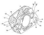
図2および図3に示すように、上記ロアリンク6は、上記クランクピン5に嵌合する円筒形のクランクピン軸受部11を中央に有し、かつこのクランクピン軸受部11を挟んで互いにほぼ180°反対側となる位置に、アッパピン用ピンボス部12およびコントロールピン用ピンボス部13がそれぞれ設けられている。ロアリンク6は、全体として、菱形に近い平行四辺形をなしており、クランクピン軸受部11の中心を通る分割面14において、アッパピン用ピンボス部12を含むロアリンクアッパ6Aと、コントロールピン用ピンボス部13を含むロアリンクロア6Bと、の2部品に分割して形成されている。これらのロアリンクアッパ6Aおよびロアリンクロア6Bは、後述する軸受メタル16を介してクランクピン軸受部11をクランクピン5に嵌め込んだ上で、クランクピン軸受部11の両側に位置する2本のボルト21,22によって互いに締結されている。2本のボルト21,22は、それぞれ分割面14に直交する方向に延びており、つまりボルト中心線が互いに平行となっている。そして、アッパピン用ピンボス部12側に位置するボルト21は、ロアリンクロア6B側のボルト孔23を貫通し、かつロアリンクアッパ6A側のネジ孔24に螺合している。コントロールピン用ピンボス部13側に位置するボルト22は、ロアリンクアッパ6A側のボルト孔25を貫通し、かつロアリンクロア6B側のネジ孔26に螺合している。 As shown in FIGS. 2 and 3, the
上記アッパピン用ピンボス部12およびコントロールピン用ピンボス部13は、アッパリンク3やコントロールリンク7を軸方向中央部に挟むように二股状の構成となっており、アッパピン4やコントロールピン9の軸方向端部をそれぞれ支持する一対の軸受フランジ部12a,13aが、ロアリンク6の軸方向の端面に沿って延びている。つまり、ピンボス部12,13を構成する各々の軸受フランジ部12a,13aは、円筒状をなすクランクピン軸受部11の軸方向両端部にそれぞれ接続されている。軸受フランジ部12a,13aは、それぞれ円形の貫通孔12b,13bを有し、円筒形をなすアッパピン4およびコントロールピン9の端部がそれぞれ圧入されている。そして、一対の軸受フランジ部12a,13aの間に構成される溝部17,18の中で、それぞれアッパリンク3およびコントロールリンク7が揺動運動する構成となっている。 The upper pin
上記クランクピン軸受部11は、半円筒形の一対の軸受メタル16を介してクランクピン5に嵌合する(図5,図6参照)。クランクピン5は、加圧された潤滑油が供給される潤滑油通路を内部に備えており、半径方向に延びた潤滑油通路の先端が油供給孔29(図1参照)としてクランクピン5の外周面に開口している。後述するようにクランクピン軸受部11には油孔30が貫通形成されており、この油孔30がクランクピン5側の油供給孔29と合致したときに油孔30から潤滑油がいわゆるオイルジェットとして噴射される構成となっている。 The
ロアリンク6は、アッパリンク3からアッパピン4を介してアッパピン用ピンボス部12に燃焼荷重が作用し、コントロールピン9を支点として揺動することで、一種の”てこ”のような動作でクランクピン5に力を伝達する。従って、アッパピン用ピンボス部12に燃焼荷重が図1の下側方向へ作用するとともにコントロールピン用ピンボス部13に燃焼荷重反力が同じく図1の下側方向へ作用するのに対し、クランクピン軸受部11中央付近にクランクピン5からの反力が図1の上側方向に作用し、これにより、ロアリンクアッパ6Aのクランクピン軸受部11の周りには大きな応力が発生する。クランクピン軸受部11の応力の周方向分布としては、概ね、クランクピン5の中心からピストン1へ向かう方向、より詳しくはアッパピン4寄りに僅かに偏った方向の部位で最大となる。他方、クランクピン軸受部11の分割面14に近い部位では、相対的に応力が小さくなる。 A combustion load acts on the upper pin
図4は、第1実施例の油孔30をクランクピン軸受部11に備えてなるロアリンクアッパ6Aの断面図(クランクピン5の軸方向と直交する面に沿った断面図)を示している。 FIG. 4 shows a cross-sectional view (a cross-sectional view along a plane orthogonal to the axial direction of the crankpin 5) of the lower link upper 6A having the
油孔30は、アッパピン用ピンボス部12においてロアリンク6と連結されるアッパリンク3の連結部つまりアッパピン4とアッパリンク3との間の摺動面を潤滑するためのもので、第1油孔31と第2油孔32とによって略L字形に構成されている。 The
第1油孔31は、クランクピン軸受部11内周面11aから半径方向外側へ直線状に延びた非貫通(つまり先端31aが封止されている)孔であり、基端が油入口31bとしてクランクピン軸受部11の内周面11aに開口している。一実施例では、第1油孔31は、分割面14に対し斜めに傾いており、かつ、クランクピン軸受部11の半径線に沿って形成されている。このようにクランクピン軸受部11の半径線に沿って第1油孔31を配置することで、油入口31bが実質的に真円形に開口することとなる。 The
また第1油孔31は、上述したクランクピン軸受部11の応力の周方向分布の中で応力が高い部位を避けるために、ロアリンク6における傾斜角度(例えば、分割面14を基準とした傾斜角度θ)が比較的小さく設定されている。図示の第1実施例では、分割面14を基準とした第1油孔31の傾斜角度θは、10°である。このように傾斜角度θが小さいことから、第1油孔31は、その中心線の延長線がアッパピン4の外周面と交差しない方向に形成されている。詳しくは、第1油孔31の中心線の延長線がアッパピン4の下側(ピストン1とは反対側)を通る。 Further, the
第2油孔32は、ロアリンク6の外側面詳しくはアッパピン4に対面する溝部17の底面17aからロアリンク6内部へと直線状に延びた非貫通(つまり先端32aが封止されている)孔であり、基端が油出口32bとして上記底面17aに開口している。ロアリンク6の内部において、第2油孔32の先端部(つまり先端32a側の部分)と第1油孔31の先端部(つまり先端31a側の部分)とが互いに交差している。つまり、第2油孔32は、第1油孔31に連通している。 The
第2油孔32は、その中心線の延長線がアッパピン4の外周面と交差する方向に形成されており、図示例では、アッパピン4の中心付近を第2油孔32が指向している。また、図示の実施例では、第2油孔32は、分割面14に直交する方向に沿って延びており、従って、隣接するボルト21および対応するネジ孔24の中心軸線に対し平行となっている。このように第2油孔32が隣接するネジ孔24に対し平行であることから、両者間の肉厚が軸方向について一定となり、局部的な薄肉化ひいては局部的な強度低下が回避される。 The
第1油孔31および第2油孔32は、クランクピン5の軸方向に対し直交する一つの平面に沿って形成されている。例えば、クランクピン軸受部11の軸方向寸法の中央を通る上記平面の上に第1油孔31および第2油孔32が位置している。なお、本発明においては、上記の平面に対し多少の角度を有する斜め方向に第1、第2油孔31,32を形成してもよいが、第1油孔31の油入口31bにおける強度確保の上では、上記の平面に沿って形成することが望ましい。 The
互いに交差する第1油孔31および第2油孔32がなす角度は、90°よりも大きい。例えば、分割面14を基準とした第1油孔31の傾斜角度θが10°であり、第2油孔32が分割面14に対し直交するとすると、第1油孔31と第2油孔32とは100°の角度で交差することとなる。このように鈍角で交差することで、潤滑油の流れに対する交差部での損失が小さなものとなる。 The angle formed by the
第1油孔31および第2油孔32は、例えば、ロアリンクアッパ6Aを鍛造で形成した後にドリルを用いた二次的な機械加工によってそれぞれ形成されている。また、ロアリンクアッパ6Aは、表面硬度を高めるために浸炭処理(浸炭焼き入れ)がなされるが、この浸炭処理の前にドリル加工を行うことが望ましい。 The
ここで好ましい一実施例においては、第2油孔32の径が第1油孔31の径よりも相対的に大きく設定されている。このように第2油孔32の径を大きくすることで第2油孔32周囲における剛性が低下し、相対的に大きな変形が生じることから、応力集中が最も問題となる第1油孔31(特にその油入口31b)周囲における応力が低下する。つまり、両者が同一の径の場合、あるいは、逆に第1油孔31が第2油孔32よりも小径である場合、に比較して、油入口31bにおける応力が緩和される。 Here, in a preferred embodiment, the diameter of the
また、このように第2油孔32の径を第1油孔31の径よりも相対的に大きくすることで、多少の加工誤差ないし公差があっても、両者の交差部において連通状態を確実に確保することができ、所定の通路断面積が安定的に得られる。 Further, by making the diameter of the
なお、図示例では、ドリル加工の都合上、第2油孔32の先端32aが第1油孔31を横切ってさらに僅かに延びているが、加工が可能であれば、このような余剰の通路部分は不要である。 In the illustrated example, the
上記のように構成された実施例のロアリンク6にあっては、所定のクランク角度においてクランクピン5側の油供給孔29と第1油孔31の油入口31bとが合致し、加圧されている潤滑油が第1油孔31および第2油孔32を通って油出口32bからオイルジェットとしてアッパピン4へ向けて噴出する。このオイルジェットによって、アッパピン4とアッパリンク3との間が潤滑される。 In the
ここで、第1油孔31は、分割面14に対する傾斜角度θが比較的に小さく、分割面14に近い位置に油入口31bが開口するので、油入口31bの開口縁における応力集中が緩和される。例えば、図4と同一のアッパピン4等の配置を前提として、クランクピン軸受部11の半径線に沿ってアッパピン4と交差し得る方向に直線的に油孔を貫通形成したとすると、分割面14に対する傾斜角度θは40°前後の角度となる。この角度方向は、クランクピン軸受部11の周方向の応力分布の中でかなり応力が高い部位を通過することとなる。これに対し、上記実施例では、油孔30を第1油孔31と第2油孔32とから構成することで、油入口31bが分割面14に近い位置となり、応力集中を抑制する上で有利である。 Here, since the
ところで、上記のように分割面14を基準とした第1油孔31の傾斜角度θが小さくなると、ロアリンク6の揺動運動およびクランクピン5の旋回運動の中でクランクピン5に対する油入口31bの周方向速度が高くなる(例えば上述した傾斜角度θが40°程度の場合に比較して)。そのため、クランクピン5側の油供給孔29と油入口31bとが合致する時間が相対的に短くなり、潤滑油量が減少する傾向となる。そのため、好ましい一実施例においては、図5に示すように、軸受メタル16の連通孔41を周方向に長くなった長孔状に形成する。 By the way, when the inclination angle θ of the
すなわち、軸受メタル16は、全体として円筒状をなすように180°ずつ2分割して構成されており、ロアリンクアッパ6Aおよびロアリンクロア6Bにそれぞれ非回転状態に組み付けられるものである。この軸受メタル16には、クランクピン5側の油供給孔29とロアリンク6の油入口31bとを互いに連通させるために、油入口31bに対応する位置に連通孔41が形成されている。そして、この連通孔41は、周方向に延びた長孔状をなしている。これにより、クランクピン5側の油供給孔29とロアリンク6の油入口31bとが所定角度範囲に亘って連通状態に保たれる。換言すれば、クランクピン5側の油供給孔29とロアリンク6の油入口31bとが互いに連通する時間が長くなる。従って、十分な潤滑油量が確保される。 That is, the bearing
一実施例においては、図6に示すように、長孔状をなす連通孔41の一端は油入口31bに対応する位置にあり、他端は、分割面14を基準とした傾斜角度θがより大きくなる位置まで延びている。 In one embodiment, as shown in FIG. 6, one end of the elongated
なお、連通孔41を過度に大きくすると軸受としての面圧が高くなるので好ましくない。 It should be noted that if the
第1油孔31の分割面14を基準とした傾斜角度θは、上記第1実施例では10°を例に説明したが、本発明において、第1油孔31の傾斜角度θは特定の角度に限定されるものではない。図7~図9は、クランクピン軸受部11の半径線に沿った第1油孔31の傾斜角度θを例えば24°とした第2実施例のロアリンク6を示している。他の構成は、基本的に第1実施例と同様である。第1油孔31は、やはり、その中心線の延長線がアッパピン4と交差しない方向を指向しており、潤滑油は、第2油孔32を介してアッパピン4側へ案内される。 The inclination angle .theta. of the
この第2実施例では、交差部における第1油孔31と第2油孔32との交差角度が第1実施例よりも大きくなり、流れの方向変化に伴う圧力損失は小さい。また、第2油孔32の通路長さが第1実施例に比較して短くなり、この点でも圧力損失が小さくなる。その反面、第1油孔31の油入口31bの位置は、応力の高い部位に近づくこととなる。従って、両者を勘案して傾斜角度θを設定することが望ましい。 In the second embodiment, the intersection angle between the
第2実施例においても、軸受メタル16の連通孔41は長孔状に形成されているが、第1実施例に比較して第1油孔31の傾斜角度θが大きいので、長孔状をなす連通孔41の周方向中央付近に第1油孔31の油入口31bが位置している(図9参照)。 In the second embodiment as well, the communicating
なお、第1,第2実施例のロアリンクアッパ6A(ロアリンク6)は、上記の油孔30のほかに、ピストン1(図1参照)ないしシリンダ内壁面へ向かってオイルジェットを供給するための油孔28を備えている。この油孔28は、クランクピン軸受部11の円周の中で最大燃焼荷重反力が作用する位置よりもコントロールピン9寄りに位置している。そのため、前述した燃焼荷重および燃焼荷重反力による開口縁での応力集中は比較的に少ない。従って、油孔28は単純な直線状に形成されている。この油孔28に対応する軸受メタル16の連通孔42は、真円形をなしている(図5,図6,図9参照)。 The lower link upper 6A (lower link 6) of the first and second embodiments supplies an oil jet not only to the
以上、この発明の一実施例を詳細に説明したが、この発明は上記実施例に限られず、適宜な変更が可能である。例えば、上記実施例では、第1油孔31がクランクピン軸受部11の半径線に沿って形成されているが、クランクピン軸受部11の半径線に対し多少傾いていてもよく、あるいは、半径線に対して僅かに平行移動させたような配置であってもよい。 Although one embodiment of the present invention has been described in detail above, the present invention is not limited to the above embodiment, and appropriate modifications are possible. For example, in the above embodiment, the
また、第2油孔32は、分割面14に対して直交する方向(つまりボルト21に平行な方向)に厳密に沿っていなくてもよい。 Further, the
Claims (7)
上記油孔は、
上記クランクピン軸受部内周面から半径方向外側へ直線状に延びた第1油孔と、
上記第1油孔の先端部と交差し、一端が油出口としてロアリンク外側面に開口した直線状に延びた第2油孔と、
から構成されている、内燃機関のロアリンク。An upper link having one end connected to a piston of an internal combustion engine via a piston pin, a lower link connected to the other end of the upper link via an upper pin and to a crankpin of a crankshaft, and an engine having one end a control link swingably supported on the body side, the other end of which is connected to the lower link via a control pin; A crank pin bearing portion rotatably fitted to the crank pin is provided between the crank pin and the control pin, and lubricating oil is supplied from an oil supply hole of the crank pin toward a connecting portion between the upper pin and the upper link. In a lower link of an internal combustion engine in which an oil hole is formed through the crankpin bearing portion,
The oil hole
a first oil hole linearly extending radially outward from the inner peripheral surface of the crankpin bearing;
a linearly extending second oil hole which intersects with the tip of the first oil hole and whose one end is open to the outer surface of the lower link as an oil outlet;
A lower link of an internal combustion engine, which consists of
上記第1油孔は上記分割面に対し斜めに傾いた方向に延びており、
上記第2油孔は上記分割面に直交する方向に延びている、
請求項1~3のいずれかに記載の内燃機関のロアリンク。The lower link is divided into a lower link upper including an upper pin pin boss portion and a lower link lower including a control pin pin boss portion on a split plane passing through the center of the crank pin. are fastened together by a plurality of bolts extending in a direction orthogonal to the dividing plane,
The first oil hole extends in a direction oblique to the dividing surface,
The second oil hole extends in a direction perpendicular to the dividing surface,
A lower link for an internal combustion engine according to any one of claims 1 to 3.
上記第2油孔は、その中心線の延長線が上記アッパピンの外周面と交差する方向に形成されている、
請求項1~4のいずれかに記載の内燃機関のロアリンク。The first oil hole is formed in a direction in which an extension of the center line thereof does not intersect the outer peripheral surface of the upper pin,
The second oil hole is formed in a direction in which an extension of the center line of the second oil hole intersects the outer peripheral surface of the upper pin.
A lower link for an internal combustion engine according to any one of claims 1 to 4.
請求項1~5のいずれかに記載の内燃機関のロアリンク。The first oil hole is formed along a radial line of the crankpin bearing portion,
A lower link for an internal combustion engine according to any one of claims 1 to 5.
上記軸受メタルに、上記クランクピンの油供給孔と上記第1油孔とを所定角度範囲に亘って連通状態に保つ長孔状の連通孔が開口形成されている、
請求項1~6のいずれかに記載の内燃機関のロアリンク。The crankpin bearing portion is fitted to the crankpin via a bearing metal,
An elongated communication hole is formed in the bearing metal to keep the oil supply hole of the crankpin and the first oil hole in communication over a predetermined angular range.
A lower link for an internal combustion engine according to any one of claims 1 to 6.
Applications Claiming Priority (1)
| Application Number | Priority Date | Filing Date | Title |
|---|---|---|---|
| PCT/IB2020/000771 WO2022058766A1 (en) | 2020-09-15 | 2020-09-15 | Lower link of internal combustion engine |
Publications (2)
| Publication Number | Publication Date |
|---|---|
| JPWO2022058766A1 JPWO2022058766A1 (en) | 2022-03-24 |
| JP7338796B2 true JP7338796B2 (en) | 2023-09-05 |
Family
ID=80776637
Family Applications (1)
| Application Number | Title | Priority Date | Filing Date |
|---|---|---|---|
| JP2022550046A Active JP7338796B2 (en) | 2020-09-15 | 2020-09-15 | Internal combustion engine lower link |
Country Status (5)
| Country | Link |
|---|---|
| US (1) | US20240035401A1 (en) |
| EP (1) | EP4215724A4 (en) |
| JP (1) | JP7338796B2 (en) |
| CN (1) | CN116034215A (en) |
| WO (1) | WO2022058766A1 (en) |
Citations (5)
| Publication number | Priority date | Publication date | Assignee | Title |
|---|---|---|---|---|
| JP2010185329A (en) | 2009-02-12 | 2010-08-26 | Nissan Motor Co Ltd | Multi-link type piston crank mechanism of internal combustion engine |
| WO2015025683A1 (en) | 2013-08-22 | 2015-02-26 | 日産自動車株式会社 | Double-link piston crank mechanism for internal combustion engine |
| WO2016042605A1 (en) | 2014-09-17 | 2016-03-24 | 日産自動車株式会社 | Internal combustion engine |
| JP2016196888A (en) | 2016-06-27 | 2016-11-24 | 日産自動車株式会社 | Lubricating structure of multi-link type piston/crank mechanism of internal combustion engine |
| JP2019148247A (en) | 2018-02-28 | 2019-09-05 | 日産自動車株式会社 | Double-link type piston crank mechanism of internal combustion engine |
Family Cites Families (5)
| Publication number | Priority date | Publication date | Assignee | Title |
|---|---|---|---|---|
| JP4646879B2 (en) * | 2006-09-08 | 2011-03-09 | 本田技研工業株式会社 | Variable stroke characteristics engine |
| US20120111143A1 (en) * | 2009-07-17 | 2012-05-10 | Nissan Motor Co., Ltd. | Crankshaft of internal combustion engine provided with multi link-type piston-crank mechanism and multi link-type piston-crank mechanism of internal combustion engine |
| JP6036006B2 (en) * | 2012-08-24 | 2016-11-30 | 日産自動車株式会社 | Lubrication structure of a multi-link piston-crank mechanism of an internal combustion engine |
| EP3346107B1 (en) * | 2015-09-04 | 2019-12-04 | Nissan Motor Co., Ltd. | Piston crank mechanism with lubrication structure and lubrication method for upper pin in piston crank mechanism of internal combustion engine |
| JP6916474B2 (en) * | 2018-01-31 | 2021-08-11 | 日産自動車株式会社 | Link parts with oil holes |
-
2020
- 2020-09-15 EP EP20954022.8A patent/EP4215724A4/en active Pending
- 2020-09-15 CN CN202080105133.9A patent/CN116034215A/en active Pending
- 2020-09-15 US US18/026,307 patent/US20240035401A1/en active Pending
- 2020-09-15 JP JP2022550046A patent/JP7338796B2/en active Active
- 2020-09-15 WO PCT/IB2020/000771 patent/WO2022058766A1/en unknown
Patent Citations (5)
| Publication number | Priority date | Publication date | Assignee | Title |
|---|---|---|---|---|
| JP2010185329A (en) | 2009-02-12 | 2010-08-26 | Nissan Motor Co Ltd | Multi-link type piston crank mechanism of internal combustion engine |
| WO2015025683A1 (en) | 2013-08-22 | 2015-02-26 | 日産自動車株式会社 | Double-link piston crank mechanism for internal combustion engine |
| WO2016042605A1 (en) | 2014-09-17 | 2016-03-24 | 日産自動車株式会社 | Internal combustion engine |
| JP2016196888A (en) | 2016-06-27 | 2016-11-24 | 日産自動車株式会社 | Lubricating structure of multi-link type piston/crank mechanism of internal combustion engine |
| JP2019148247A (en) | 2018-02-28 | 2019-09-05 | 日産自動車株式会社 | Double-link type piston crank mechanism of internal combustion engine |
Also Published As
| Publication number | Publication date |
|---|---|
| CN116034215A (en) | 2023-04-28 |
| WO2022058766A1 (en) | 2022-03-24 |
| EP4215724A4 (en) | 2023-11-01 |
| EP4215724A1 (en) | 2023-07-26 |
| JPWO2022058766A1 (en) | 2022-03-24 |
| US20240035401A1 (en) | 2024-02-01 |
Similar Documents
| Publication | Publication Date | Title |
|---|---|---|
| JP5298911B2 (en) | Double link piston crank mechanism for internal combustion engine | |
| US20120111143A1 (en) | Crankshaft of internal combustion engine provided with multi link-type piston-crank mechanism and multi link-type piston-crank mechanism of internal combustion engine | |
| US7290508B2 (en) | Lower link for piston crank mechanism of internal combustion engine | |
| JP4730152B2 (en) | Lower link in piston crank mechanism of internal combustion engine | |
| US9856907B2 (en) | Double-link piston crank mechanism for internal combustion engine | |
| JP6132057B2 (en) | Lubrication structure of a multi-link piston-crank mechanism of an internal combustion engine | |
| US8826882B2 (en) | Lubricating structure of multi-link piston-crank mechanism for internal combustion engine | |
| JP5251576B2 (en) | Double link piston crank mechanism for internal combustion engine | |
| JP6160779B2 (en) | Bearing structure | |
| JP2011017399A (en) | Crankshaft of internal combustion engine equipped with double link type piston crank mechanism | |
| JP7338796B2 (en) | Internal combustion engine lower link | |
| JP6961514B2 (en) | Double link type piston crank mechanism of internal combustion engine | |
| JP5205991B2 (en) | Link mechanism bearing structure | |
| JP7335195B2 (en) | Internal combustion engine lower link | |
| KR20110100220A (en) | Piston bearing arrangement | |
| JP5321724B2 (en) | Link mechanism bearing structure | |
| JP2019148169A (en) | Double-link type piston crank mechanism of internal combustion engine | |
| JP7099169B2 (en) | Double link type piston crank mechanism of internal combustion engine | |
| JP2010203270A (en) | Lubricating device of double-link type internal combustion engine | |
| JP4858246B2 (en) | Link assembly | |
| JP4670342B2 (en) | Lower link in piston crank mechanism of internal combustion engine | |
| JP5321148B2 (en) | Double link variable compression ratio internal combustion engine | |
| JP2016037944A (en) | Bearing structure of double link type piston crank mechanism of internal combustion engine | |
| JP4752545B2 (en) | Lower link in piston crank mechanism of internal combustion engine | |
| JP2021161975A (en) | Link member of internal combustion engine and manufacturing method thereof |
Legal Events
| Date | Code | Title | Description |
|---|---|---|---|
| A621 | Written request for application examination |
Free format text: JAPANESE INTERMEDIATE CODE: A621 Effective date: 20230213 |
|
| TRDD | Decision of grant or rejection written | ||
| A01 | Written decision to grant a patent or to grant a registration (utility model) |
Free format text: JAPANESE INTERMEDIATE CODE: A01 Effective date: 20230725 |
|
| A61 | First payment of annual fees (during grant procedure) |
Free format text: JAPANESE INTERMEDIATE CODE: A61 Effective date: 20230807 |
|
| R151 | Written notification of patent or utility model registration |
Ref document number: 7338796 Country of ref document: JP Free format text: JAPANESE INTERMEDIATE CODE: R151 |