RU2616912C2 - Lighting system - Google Patents
Lighting system Download PDFInfo
- Publication number
- RU2616912C2 RU2616912C2 RU2014118726A RU2014118726A RU2616912C2 RU 2616912 C2 RU2616912 C2 RU 2616912C2 RU 2014118726 A RU2014118726 A RU 2014118726A RU 2014118726 A RU2014118726 A RU 2014118726A RU 2616912 C2 RU2616912 C2 RU 2616912C2
- Authority
- RU
- Russia
- Prior art keywords
- lamp
- holder
- lighting system
- light emitting
- lamp holder
- Prior art date
Links
- 230000001681 protective effect Effects 0.000 claims abstract description 31
- 238000007789 sealing Methods 0.000 claims abstract description 14
- 239000000428 dust Substances 0.000 abstract description 25
- 230000000694 effects Effects 0.000 abstract 1
- 239000000126 substance Substances 0.000 abstract 1
- XLYOFNOQVPJJNP-UHFFFAOYSA-N water Substances O XLYOFNOQVPJJNP-UHFFFAOYSA-N 0.000 description 5
- 238000005516 engineering process Methods 0.000 description 1
- 238000009434 installation Methods 0.000 description 1
- 238000012986 modification Methods 0.000 description 1
- 230000004048 modification Effects 0.000 description 1
- 230000003287 optical effect Effects 0.000 description 1
- 230000035515 penetration Effects 0.000 description 1
- 239000007787 solid Substances 0.000 description 1
Images

Classifications
-
- F—MECHANICAL ENGINEERING; LIGHTING; HEATING; WEAPONS; BLASTING
- F21—LIGHTING
- F21K—NON-ELECTRIC LIGHT SOURCES USING LUMINESCENCE; LIGHT SOURCES USING ELECTROCHEMILUMINESCENCE; LIGHT SOURCES USING CHARGES OF COMBUSTIBLE MATERIAL; LIGHT SOURCES USING SEMICONDUCTOR DEVICES AS LIGHT-GENERATING ELEMENTS; LIGHT SOURCES NOT OTHERWISE PROVIDED FOR
- F21K9/00—Light sources using semiconductor devices as light-generating elements, e.g. using light-emitting diodes [LED] or lasers
- F21K9/20—Light sources comprising attachment means
-
- F—MECHANICAL ENGINEERING; LIGHTING; HEATING; WEAPONS; BLASTING
- F21—LIGHTING
- F21V—FUNCTIONAL FEATURES OR DETAILS OF LIGHTING DEVICES OR SYSTEMS THEREOF; STRUCTURAL COMBINATIONS OF LIGHTING DEVICES WITH OTHER ARTICLES, NOT OTHERWISE PROVIDED FOR
- F21V21/00—Supporting, suspending, or attaching arrangements for lighting devices; Hand grips
- F21V21/02—Wall, ceiling, or floor bases; Fixing pendants or arms to the bases
-
- F—MECHANICAL ENGINEERING; LIGHTING; HEATING; WEAPONS; BLASTING
- F21—LIGHTING
- F21V—FUNCTIONAL FEATURES OR DETAILS OF LIGHTING DEVICES OR SYSTEMS THEREOF; STRUCTURAL COMBINATIONS OF LIGHTING DEVICES WITH OTHER ARTICLES, NOT OTHERWISE PROVIDED FOR
- F21V31/00—Gas-tight or water-tight arrangements
- F21V31/005—Sealing arrangements therefor
-
- F—MECHANICAL ENGINEERING; LIGHTING; HEATING; WEAPONS; BLASTING
- F21—LIGHTING
- F21V—FUNCTIONAL FEATURES OR DETAILS OF LIGHTING DEVICES OR SYSTEMS THEREOF; STRUCTURAL COMBINATIONS OF LIGHTING DEVICES WITH OTHER ARTICLES, NOT OTHERWISE PROVIDED FOR
- F21V31/00—Gas-tight or water-tight arrangements
- F21V31/03—Gas-tight or water-tight arrangements with provision for venting
-
- F—MECHANICAL ENGINEERING; LIGHTING; HEATING; WEAPONS; BLASTING
- F21—LIGHTING
- F21V—FUNCTIONAL FEATURES OR DETAILS OF LIGHTING DEVICES OR SYSTEMS THEREOF; STRUCTURAL COMBINATIONS OF LIGHTING DEVICES WITH OTHER ARTICLES, NOT OTHERWISE PROVIDED FOR
- F21V31/00—Gas-tight or water-tight arrangements
- F21V31/04—Provision of filling media
-
- F—MECHANICAL ENGINEERING; LIGHTING; HEATING; WEAPONS; BLASTING
- F21—LIGHTING
- F21W—INDEXING SCHEME ASSOCIATED WITH SUBCLASSES F21K, F21L, F21S and F21V, RELATING TO USES OR APPLICATIONS OF LIGHTING DEVICES OR SYSTEMS
- F21W2111/00—Use or application of lighting devices or systems for signalling, marking or indicating, not provided for in codes F21W2102/00 – F21W2107/00
- F21W2111/04—Use or application of lighting devices or systems for signalling, marking or indicating, not provided for in codes F21W2102/00 – F21W2107/00 for waterways
-
- F—MECHANICAL ENGINEERING; LIGHTING; HEATING; WEAPONS; BLASTING
- F21—LIGHTING
- F21W—INDEXING SCHEME ASSOCIATED WITH SUBCLASSES F21K, F21L, F21S and F21V, RELATING TO USES OR APPLICATIONS OF LIGHTING DEVICES OR SYSTEMS
- F21W2131/00—Use or application of lighting devices or systems not provided for in codes F21W2102/00-F21W2121/00
- F21W2131/40—Lighting for industrial, commercial, recreational or military use
- F21W2131/401—Lighting for industrial, commercial, recreational or military use for swimming pools
-
- F—MECHANICAL ENGINEERING; LIGHTING; HEATING; WEAPONS; BLASTING
- F21—LIGHTING
- F21Y—INDEXING SCHEME ASSOCIATED WITH SUBCLASSES F21K, F21L, F21S and F21V, RELATING TO THE FORM OR THE KIND OF THE LIGHT SOURCES OR OF THE COLOUR OF THE LIGHT EMITTED
- F21Y2115/00—Light-generating elements of semiconductor light sources
- F21Y2115/10—Light-emitting diodes [LED]
Landscapes
- Engineering & Computer Science (AREA)
- General Engineering & Computer Science (AREA)
- Physics & Mathematics (AREA)
- Microelectronics & Electronic Packaging (AREA)
- Optics & Photonics (AREA)
- Non-Portable Lighting Devices Or Systems Thereof (AREA)
- Arrangement Of Elements, Cooling, Sealing, Or The Like Of Lighting Devices (AREA)
- Fastening Of Light Sources Or Lamp Holders (AREA)
Abstract
Description
Область техники, к которой относится изобретениеFIELD OF THE INVENTION
Настоящее изобретение относится к области осветительных модулей, и в частности, к осветительной системе, состоящей из держателя светильника и модуля светильника. Более точно, настоящее изобретение относится к области светоизлучающих диодов (СИД), приводимых в действие осветительными модулями.The present invention relates to the field of lighting modules, and in particular, to a lighting system consisting of a lamp holder and a lamp module. More specifically, the present invention relates to the field of light emitting diodes (LEDs) driven by lighting modules.
Уровень техникиState of the art
Все большее число СИД, приводимых в действие светильниками, находятся сегодня на рынке. Многие из этих систем оснащены СИД модулями, которые содержат множество светоизлучающих диодов, СИД. СИД модуль обычно помещается или устанавливается в держатель лампы.A growing number of LEDs powered by luminaires are on the market today. Many of these systems are equipped with LED modules, which contain many light emitting diodes, LEDs. An LED module is usually placed or mounted in a lamp holder.
Промышленность и другие субъекты в этой области, в настоящее время сотрудничают с целью разработки типовых технических условий для интерфейсов СИД источников света. СИД источник света является СИД модулем с определенными интерфейсами, которые не зависят от типа СИД технологии, используемой внутри источника света. Например, типовые технические условия для монтажа и электрического подключения СИД модулей могут определять электрические, механические, а также тепловые интерфейсы и обеспечивать взаимозаменяемость между продукцией, выпускаемой различными производителями. Другими словами, это позволяет потребителям обменивать СИД модули марки А на марку В. Таким образом, нет необходимости менять разъемы или светильники, когда потребитель хочет заменить СИД модуль.Industry and other entities in this field are currently collaborating to develop model specifications for the LED interfaces of light sources. An LED light source is an LED module with specific interfaces that are independent of the type of LED technology used inside the light source. For example, typical specifications for the installation and electrical connection of LED modules can determine electrical, mechanical, as well as thermal interfaces and provide interchangeability between products manufactured by different manufacturers. In other words, this allows consumers to exchange brand A LED modules for brand B. Thus, there is no need to change the connectors or fixtures when the consumer wants to replace the LED module.
Взаимозаменяемость достигается путем определения интерфейсов для многообразия конкретного применения источников света. Типовые технические условия могут охватывать физические размеры, а также фотометрический, электрический и температурный режим СИД источников света.Interchangeability is achieved by defining interfaces for the diversity of a particular application of light sources. Typical specifications may cover physical dimensions as well as the photometric, electrical, and temperature conditions of LED light sources.
Стандарты освещения могут быть реализованы во многих областях: освещения домов, магазинов, офисов, а также вне помещений. Во многих этих применениях часто возникает потребность в высокой пылевлагозащите, IP. Оценка пылевлагозащиты классифицируется и определяется степенью принятия мер против проникновения твердых предметов (включая части тела, такие как руки и пальцы), пыли, случайного касания и воды в механические корпусы и электрические оболочки. Стандартными целями оценки пылевлагозащиты является обеспечить более подробной информацией, нежели расплывчатые маркетинговые термины, такие как водонепроницаемость.Lighting standards can be implemented in many areas: lighting houses, shops, offices, as well as outdoors. In many of these applications, the need for high dust and water protection, IP, often arises. The assessment of dust and moisture protection is classified and determined by the degree to which measures are taken against the penetration of solid objects (including body parts such as hands and fingers), dust, accidental contact and water in mechanical housings and electrical enclosures. The standard objectives for evaluating dust and moisture protection are to provide more detailed information than vague marketing terms such as water resistance.
Одним из недостатков стандартов, рассмотренных выше, является то, что интерфейс не содержит в себе пылевлагозащиту. Поэтому, это полностью зависит от производителя светильника обеспечить пылевлагозащиту при создании конструкции. Дополнительно, часто бывает трудно реализовать высокую степень пылевлагозащиты без создания громоздкой конструкции. Кроме того, другим недостатком является то, что дополнительные светопотери будут возникать потому, что СИД модуль должен быть полностью окружен пылевлагозащитным кожухом.One of the drawbacks of the standards discussed above is that the interface does not contain dust and moisture protection. Therefore, it completely depends on the manufacturer of the lamp to provide dust and moisture protection when creating the structure. Additionally, it is often difficult to realize a high degree of dust and moisture protection without creating a bulky design. In addition, another disadvantage is that additional light losses will occur because the LED module must be completely surrounded by a dust and moisture protection cover.
Для этих видов применений, где такие стандарты освещения реализуются, существует потребность в компактном и простом решении, как реализовать СИД светильник, имеющий как высокую степень пылевлагозащиты, так и оптимальную светоотдачу.For these types of applications where such lighting standards are being implemented, there is a need for a compact and simple solution, how to implement an LED lamp having both a high degree of dust and moisture protection and optimal light output.
Раскрытие изобретенияDisclosure of invention
В связи с вышеизложенным, желательно обеспечить осветительной системой, которая может облегчить взаимозаменяемость между различными марками модулей светильника и держателей светильника. Также желательно обеспечить осветительной системой, имеющей высокую степень пылевлагозащиты, сохраняя, при этом, оптимальную светоотдачу, что позволяет избежать дополнительной светопотери.In connection with the foregoing, it is desirable to provide a lighting system that can facilitate interchangeability between different brands of lamp modules and lamp holders. It is also desirable to provide a lighting system having a high degree of dust and moisture protection, while maintaining, at the same time, optimal light output, which avoids additional light loss.
Кроме того, желательно обеспечить осветительной системой, которая может содержать в себе высокую пылевлагозащиту, не создавая громоздкой конструкции.In addition, it is desirable to provide a lighting system that can contain high dust and moisture protection without creating a bulky design.
Как правило, вышеуказанные задачи достигаются посредством систем и устройств в соответствии с прилагаемыми независимыми пунктами формулы изобретения.Typically, the above objectives are achieved by systems and devices in accordance with the attached independent claims.
Задачей текущего изобретения является обеспечить системой, которая решает или, по меньшей мере, смягчает проблемы, рассмотренные выше.The objective of the present invention is to provide a system that solves or at least mitigates the problems discussed above.
В соответствии с первым аспектом изобретения эта и другие задачи достигаются осветительной системой, содержащей держатель светильника, выполненный с возможностью быть присоединенным к плоскости основания, и содержащий разъемы электросхемы, кольцевые уплотнения, предусмотренные на упомянутых разъемах электросхемы, и защитный экран, и модуль светильника, содержащий крышку и выполненный с возможностью размещения в упомянутом держателе светильника, при этом упомянутый защитный экран и упомянутая крышка выполнены с возможностью образования герметизирующего зацепления между упомянутым держателем светильника и упомянутым модулем светильника, когда упомянутый модуль светильника размещен в упомянутом держателе светильника.In accordance with the first aspect of the invention, this and other tasks are achieved by a lighting system comprising a lamp holder configured to be connected to a base plane and comprising electrical circuit connectors, ring seals provided on said electrical circuit connectors, and a protective shield, and a lamp module comprising a lid and adapted to be placed in said lamp holder, wherein said protective shield and said lid are configured to a sealing engagement between said lamp holder and said lamp module when said lamp module is located in said lamp holder.
Предпочтительно такая осветительная система может обеспечить улучшенный интерфейс между модулем светильника и держателем светильника. Таким образом, недостатки стандартов устраняются.Preferably, such a lighting system can provide an improved interface between the lamp module and the lamp holder. In this way, the flaws of the standards are eliminated.
Другими словами, осветительная система в соответствии с настоящим изобретением включает в себя пылевлагозащиту таким способом, что водонепроницаемая защита образовывается, как только модуль светильника вставлен в держатель светильника.In other words, the lighting system in accordance with the present invention includes dust and water protection in such a way that a waterproof protection is formed as soon as the lamp module is inserted into the lamp holder.
Еще одним преимуществом разработанной осветительной системы является то, что высокая пылевлагозащита может быть достигнута в маленькой и компактной конструкции. Поэтому нет необходимости для создателя светильника делать громоздкую конструкцию, добавляя дополнительную крышку для достижения высокой степени пылевлагозащиты.Another advantage of the developed lighting system is that high dust and moisture protection can be achieved in a small and compact design. Therefore, there is no need for the creator of the lamp to make a bulky design, adding an additional cover to achieve a high degree of dust and moisture protection.
Основной составной частью изобретения является то, что держатель лампы, или держатель светильника, заботится о водонепроницаемом соединении между плоскостью основания и держателем лампы и водонепроницаемом соединении сетевых проводов. С этой целью защитный экран добавлен к держателю лампы. СИД модуль, или модуль светильника, соответствуют дополнительной юбке. Юбка и защитный экран образуют водонепроницаемую защиту, как только СИД модуль вставлен в держатель. Юбка не блокирует, или не закрывает, светоизлучающее отверстие СИД модуля. Таким образом, водонепроницаемый светильник может быть создан со 100% оптической эффективностью. Никаких дополнительных крышек не требуется. Составной частью настоящего изобретения является то, что часть пылевлагозащиты реализуется в держателе лампы, а часть в интерфейсе между держателем лампы и СИД модулем. Кроме того, возможно достичь совместимости между установленной нижней пылевлагозащитой и установленной верхней пылевлагозащитой держателя светильника и модуля светильника. Пылевлагозащита обеспечивается юбкой, прикрепленной к СИД модулю, и защитным кольцом, установленным на держателе лампы/патроне. Кроме того, три резиновых уплотнения могут быть использованы для создания водонепроницаемого интерфейса: уплотнительное кольцо между защитным экраном на держателе светильника и плоскостью основания; кольцеобразное уплотнение на кабельном вводе и "О"-образное кольцо между юбкой на СИД модуле и защитным экраном на держателе светильника.The main component of the invention is that the lamp holder, or lamp holder, takes care of the waterproof connection between the base plane and the lamp holder and the waterproof connection of the mains wires. For this purpose, a protective shield is added to the lamp holder. The LED module, or lamp module, corresponds to an additional skirt. The skirt and protective shield form a waterproof protection as soon as the LED module is inserted into the holder. The skirt does not block or block the light-emitting hole of the LED module. Thus, a waterproof luminaire can be created with 100% optical efficiency. No additional covers are required. An integral part of the present invention is that part of the dust and moisture protection is implemented in the lamp holder, and part in the interface between the lamp holder and the LED module. In addition, it is possible to achieve compatibility between the installed lower dust and moisture protection and the installed upper dust and moisture protection of the lamp holder and the lamp module. Dust and moisture protection is provided by a skirt attached to the LED module and a protective ring mounted on the lamp holder / lampholder. In addition, three rubber seals can be used to create a waterproof interface: a sealing ring between the protective shield on the lamp holder and the base plane; an O-ring on the cable entry and an “O” -shaped ring between the skirt on the LED module and the protective shield on the lamp holder.
В вышеупомянутом варианте осуществления осветительная система может дополнительно содержать уплотнение, установленное между защитным экраном и плоскостью основания, при этом уплотнение выполнено с возможностью образования герметизирующего зацепления между осветительной системой и плоскостью основания.In the aforementioned embodiment, the lighting system may further comprise a seal mounted between the protective shield and the base plane, wherein the seal is configured to form a sealing engagement between the lighting system and the base plane.
Таким образом, держатель светильника, содержащий защитный экран, заботится о пылевлагозащите или водонепроницаемом соединении между плоскостью основания и держателем светильника.Thus, the luminaire holder containing the protective shield takes care of the dust and water tightness or the waterproof connection between the base plane and the luminaire holder.
В вышеупомянутом варианте осуществления осветительная система может содержать светоизлучающее отверстие, а герметизирующее зацепление между держателем светильника и модулем светильника может быть образовано так, что светоизлучающее отверстие остается открытым, когда модуль светильника размещен в держателе светильника.In the aforementioned embodiment, the lighting system may include a light emitting hole, and a sealing engagement between the lamp holder and the lamp module can be formed so that the light emitting hole remains open when the lamp module is placed in the lamp holder.
Таким образом, модуль светильника, через его крышку, и держатель светильника, через его защитный экран, оба заботятся о водонепроницаемой защите, как только модуль светильника вставлен в держатель светильника.Thus, the luminaire module, through its lid, and the luminaire holder, through its protective shield, both take care of waterproof protection as soon as the luminaire module is inserted into the luminaire holder.
В вышеупомянутом варианте осуществления модуль светильника может быть светоизлучающим диодным модулем, СИД модулем, содержащим множество светоизлучающих диодов.In the above embodiment, the luminaire module may be a light emitting diode module, an LED module comprising a plurality of light emitting diodes.
В вышеупомянутом варианте осуществления по меньшей мере одно уплотнение, или так называемое "О"-образное кольцо, может быть прикреплено к защитному экрану держателя светильника. Этот вариант осуществления может, естественно, дополнительно улучшить степень пылевлагозащиты.In the aforementioned embodiment, at least one seal, or the so-called “O” -shaped ring, can be attached to the protective shield of the lamp holder. This embodiment may naturally further improve the degree of dust and moisture protection.
В другом варианте осуществления по меньшей мере одна прокладка может быть прикреплена к крышке модуля светильника, посредством чего степень пылевлагозащиты также может быть дополнительно улучшена.In another embodiment, at least one gasket can be attached to the lid of the lamp module, whereby the degree of dust and moisture protection can also be further improved.
В вышеупомянутом варианте осуществления крышка на модуле светильника может быть объединенным покрывающим устройством, содержащим крышку и по меньшей мере одну прокладку. Таким образом, количество требуемых компонентов может быть существенно снижено.In the aforementioned embodiment, the lid on the luminaire module may be an integrated covering device comprising a lid and at least one gasket. Thus, the number of required components can be significantly reduced.
В вышеупомянутом варианте осуществления, когда осветительная система содержит уплотнение, установленное между защитным экраном и плоскостью основания, защитный экран на держателе светильника может быть объединенным защитным экранирующим устройством, содержащим кольцевые уплотнения, уплотнение и по меньшей мере одну прокладку.In the aforementioned embodiment, when the lighting system comprises a seal installed between the protective shield and the base plane, the protective shield on the lamp holder may be a combined protective shielding device comprising o-rings, a seal and at least one gasket.
В еще одном варианте осуществления осветительной системы по меньшей мере одна прокладка может быть расположена между держателем светильника и плоскостью основания.In yet another embodiment of the lighting system, at least one gasket may be located between the lamp holder and the base plane.
В другом варианте осуществления по меньшей мере одна прокладка может быть прикреплена к плоскости основания.In another embodiment, at least one gasket may be attached to the plane of the base.
В соответствии со вторым аспектом изобретения вышеприведенная задача и другие задачи достигаются держателем светильника, выполненным с возможностью быть прикрепленным к плоскости основания и содержащим разъемы электросхемы, кольцевые уплотнения, предусмотренные на упомянутых разъемах электросхемы, и защитный экран, при этом упомянутый держатель светильника выполнен с возможностью образования части осветительной системы согласно любому из вариантов осуществления первого аспекта настоящего изобретения.In accordance with a second aspect of the invention, the foregoing task and other tasks are achieved by a lamp holder configured to be attached to a base plane and comprising electrical circuit connectors, ring seals provided on said electrical circuit connectors, and a protective shield, wherein said lamp holder is configured to form parts of a lighting system according to any one of the embodiments of the first aspect of the present invention.
В соответствии с третьим аспектом изобретения вышеприведенная задача и другие задачи достигаются модулем светильника, выполненным с возможностью излучать свет через светоизлучающее отверстие и размещаться в держателе светильника и содержащим крышку, при этом упомянутый модуль светильника выполнен с возможностью образования части осветительной системы согласно любому из вариантов осуществления первого аспекта настоящего изобретения.According to a third aspect of the invention, the above task and other tasks are achieved by a lamp module configured to emit light through a light emitting hole and placed in a lamp holder and comprising a cover, said lamp module being configured to form part of a lighting system according to any one of the first embodiments aspect of the present invention.
В вышеупомянутом варианте осуществления модуль светильника может быть выполнен с возможностью размещения в держателе светильника согласно второму аспекту настоящего изобретения.In the aforementioned embodiment, the lamp module may be arranged to be housed in a lamp holder according to a second aspect of the present invention.
В другом варианте осуществления держатель светильника может быть выполнен с возможностью приема модуля светильника согласно третьему аспекту настоящего изобретения.In another embodiment, the lamp holder may be configured to receive a lamp module according to a third aspect of the present invention.
Следует отметить, что изобретение относится ко всем возможным сочетаниям признаков, перечисленных в формуле изобретения. Таким образом, все признаки и преимущества первого аспекта также относятся ко второму и третьему аспектам соответственно.It should be noted that the invention relates to all possible combinations of features listed in the claims. Thus, all the features and advantages of the first aspect also apply to the second and third aspects, respectively.
Краткое описание чертежейBrief Description of the Drawings
Различные аспекты изобретения, включая его специфические признаки и преимущества, будут легко поняты из следующего подробного описания и прилагаемых чертежей, на которых:Various aspects of the invention, including its specific features and advantages, will be readily apparent from the following detailed description and the accompanying drawings, in which:
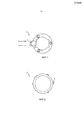
Фиг. 1 представляет собой схематичный вид сверху держателя светильника по предшествующему уровню техники.FIG. 1 is a schematic top view of a lamp holder according to the prior art.
Фиг. 2 представляет собой схематичный вид сверху модуля светильника по предшествующему уровню техники.FIG. 2 is a schematic top view of a lamp module of the prior art.
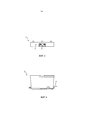
Фиг. 3 представляет собой схематичный вид сбоку держателя светильника по предшествующему уровню техники.FIG. 3 is a schematic side view of a lamp holder according to the prior art.
Фиг. 4 представляет собой схематичный вид сбоку модуля светильника по предшествующему уровню техники.FIG. 4 is a schematic side view of a prior art lamp module.
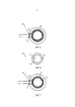
Фиг. 5 представляет собой схематичный вид сверху держателя светильника согласно варианту осуществления настоящего изобретения.FIG. 5 is a schematic plan view of a lamp holder according to an embodiment of the present invention.
Фиг. 6 представляет собой схематичный вид сверху модуля светильника согласно варианту осуществления настоящего изобретения.FIG. 6 is a schematic plan view of a lamp module according to an embodiment of the present invention.
Фиг. 7 представляет собой схематичный вид снизу держателя светильника согласно варианту осуществления настоящего изобретения.FIG. 7 is a schematic bottom view of a lamp holder according to an embodiment of the present invention.
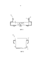
Фиг. 8 представляет собой схематичный вид сбоку держателя светильника согласно варианту осуществления настоящего изобретения.FIG. 8 is a schematic side view of a lamp holder according to an embodiment of the present invention.
Фиг. 9 представляет собой схематичный вид сбоку модуля светильника согласно варианту осуществления настоящего изобретения.FIG. 9 is a schematic side view of a lamp module according to an embodiment of the present invention.
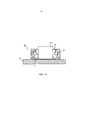
Фиг. 10-12 иллюстрируют осветительные системы согласно вариантам осуществления настоящего изобретения.FIG. 10-12 illustrate lighting systems according to embodiments of the present invention.
ОСУЩЕСТВЛЕНИЕ ИЗОБРЕТЕНИЯDETAILED DESCRIPTION OF THE INVENTION
Настоящее изобретение теперь будет описано более полно ниже со ссылкой на прилагаемые чертежи, на которых показаны предпочтительные варианты осуществления изобретения в настоящее время. Настоящее изобретение, однако, может быть воплощено во многих различных формах и не должно быть истолковано как ограничивающее для вариантов осуществления, излагаемых здесь, скорее, эти варианты осуществления предусмотрены для тщательности и полноты и полностью передают объем изобретения для специалиста в данной области. Одинаковые ссылочные позиции относятся к одинаковым элементам повсюду.The present invention will now be described more fully below with reference to the accompanying drawings, which show preferred embodiments of the invention at present. The present invention, however, can be embodied in many different forms and should not be construed as limiting for the embodiments set forth herein, rather, these embodiments are provided for thoroughness and completeness and fully convey the scope of the invention to those skilled in the art. Like numbers refer to like elements throughout.
Фиг. 1 представляет собой схематичный вид сверху держателя 1 светильника по предшествующему уровню техники, содержащего разъемы 2электросхемы, к которой сетевые кабели 3 могут быть присоединены.FIG. 1 is a schematic top view of a lamp holder 1 of the prior art, comprising
Фиг. 2 представляет собой схематичный вид сверху модуля 4 светильника по предшествующему уровню техники, содержащего сетевое соединение 5. Модуль 4 светильника по предшествующему уровню техники может быть выполнен с возможностью размещения в держателе 1 светильника, представленном на Фиг. 1.FIG. 2 is a schematic top view of a prior art lamp module 4 comprising a
Фиг. 3 представляет собой схематичный вид сбоку держателя 1 светильника, по предшествующему уровню техники, представленного на Фиг. 1. На Фиг. 3 можно видеть, что держатель 1 светильника по предшествующему уровню техники содержит основание 6, на которое может быть прикреплен электрический разъем 2.FIG. 3 is a schematic side view of the lamp holder 1 of the prior art shown in FIG. 1. In FIG. 3, it can be seen that the lamp holder 1 of the prior art comprises a
Фиг. 4 представляет собой схематичный вид сбоку модуля 4 светильника по предшествующему уровню техники, содержащего сетевое соединение 5.FIG. 4 is a schematic side view of a prior art lamp module 4 comprising a
Фиг. 5 представляет собой схематичный вид сверху держателя 10 светильника в соответствии с настоящей идеей изобретения. Держатель 10 светильника содержит разъем 12 электросхемы, на котором могут быть предусмотрены кольцевые уплотнения 14. Кольцевые уплотнения 14 обеспечивают водонепроницаемое подключение сетевых проводов 16. Держатель 10 светильника дополнительно содержит защитный экран 18, который может быть расположен вокруг держателя 10 светильника. Держатель 10 светильника может дополнительно быть выполнен с возможностью быть прикрепленным к плоскости основания.FIG. 5 is a schematic plan view of a
Фиг. 6 представляет собой схематичный вид сверху модуля 20 светильника, согласно настоящей идее изобретения. Модуль 20 светильника содержит электрический разъем 22 и светоизлучающее отверстие 17. Модуль светильника дополнительно содержит крышку 24. Крышка 24 может быть расположена вокруг модуля светильника подобно юбке.FIG. 6 is a schematic plan view of a
Фиг. 7 представляет собой схематичный вид снизу держателя 10 светильника. Держатель 10 светильника содержит уплотнение 13, расположенное между держателем 10 светильника и плоскостью основания, к которому держатель 10 светильника может быть прикреплен. Уплотнение 13 может быть установлено между защитным экраном 18 и плоскостью основания. Держатель 10 светильника может дополнительно содержать по меньшей мере одно другое уплотнение, расположенное на уплотнении 13. По меньшей мере одно другое уплотнение может быть плоским резиновым кольцом, которое может обеспечивать водонепроницаемость интерфейса между держателем 10 светильника и плоскостью основания.FIG. 7 is a schematic bottom view of a
Фиг. 8 представляет собой схематичный вид сбоку держателя 10 светильника. Держатель 10 светильника содержит основание 11, на котором расположен разъем 12 электросхемы. Держатель 10 светильника дополнительно содержит защитный экран 18, на котором может быть расположена прокладка 15. Прокладка может быть "О"-образным кольцом. Держатель 10 светильника может также содержать кольцевые уплотнения 14, расположенные на сетевом разъеме, обеспечивающие водонепроницаемое соединение сетевых проводов.FIG. 8 is a schematic side view of a
Как правило, держатель светильника способен подключить модуль светильника к питающей сети.As a rule, the lamp holder is able to connect the lamp module to the mains.
Фиг. 9 представляет собой схематичный вид сбоку модуля 20 светильника. Модуль 20 светильника содержит крышку 24, которая может быть расположена вокруг модуля 20 светильника, подобно юбке. Модуль 20 светильника дополнительно содержит электрический разъем 22.FIG. 9 is a schematic side view of a
Модуль светильника может быть светоизлучающим диодным модулем, СИД модулем, содержащим множество светоизлучающих диодов.The lamp module may be a light emitting diode module, an LED module containing a plurality of light emitting diodes.
Предпочтительно модуль светильника может иметь встроенный драйвер, устраняющий необходимость подключения дополнительного СИД драйвера к нему.Preferably, the luminaire module may have a built-in driver, eliminating the need to connect an additional LED driver to it.
Модуль светильника может иметь различные цветовые температуры, например, 2700К, 3000К, 4000К, которые все могут быть с регулируемой яркостью.The luminaire module can have different color temperatures, for example, 2700K, 3000K, 4000K, which can all be dimmable.
Фиг. 10 представляет собой схематичный вид сбоку варианта осуществления осветительной системы 30 согласно настоящей идее изобретения. Осветительная система 30 содержит держатель 10 светильника, подобный держателю, представленному на Фиг. 8, и модуль 20 светильника, подобный модулю, представленному на Фиг. 9. Держатель 10 светильника содержит основание 11, на котором расположен разъем 12 электросхемы. Держатель 10 светильника дополнительно содержит защитный экран 18, расположенный на основании 11. Модуль 20 светильника содержит крышку 24. Защитный экран 18 и крышка 24 выполнены с возможностью образования герметизирующего зацепления для образования герметичного зацепления между держателем 10 светильника и модулем 20 светильника, когда модуль светильника размещен в держателе 10 светильника.FIG. 10 is a schematic side view of an embodiment of a
Дополнительно модуль 20 светильника содержит светоизлучающее отверстие 17. Крышка 24 расположена так, что герметизирующее зацепление между держателем 10 светильника и модулем 20 светильника образовано, в известном смысле так, что светоизлучающее отверстие остается открытым, когда модуль 20 светильника размещен в держателе 10 светильника. Это дает возможность герметизирующему зацеплению обеспечить высокую пылевлагозащиту, в то же время не допустить дополнительных светопотерь.Additionally, the
В продолжение, прокладка 15 может быть расположена либо на крышке 24, либо на защитном экране 18. Прокладка 15 дополнительно повышает герметизирующее зацепление между держателем 10 светильника и модулем 20 светильника, когда они оба соединены вместе.Further, the
Осветительная система 30, показанная на Фиг. 10, дополнительно содержит уплотнение 13, установленное между защитным экраном 18 и плоскостью 32 основания. Уплотнитель 13 может быть выполнен с возможностью образования герметизирующего зацепления между осветительной системой 30 и плоскостью 32 основания. Таким образом, осветительная система заботится о водонепроницаемом соединении между держателем 10 светильника и плоскостью основания.The
Следующие варианты осуществления настоящего изобретения, которые будут описаны относительно Фиг. 11 и 12, имеют большинство аспектов, аналогичных описанному варианту осуществления по фиг. 10. Единственная разница будет рассмотрена в следующем.The following embodiments of the present invention, which will be described with respect to FIG. 11 and 12 have most aspects similar to the described embodiment of FIG. 10. The only difference will be discussed in the following.
Фиг. 11 представляет собой схематичный вид сбоку варианта осуществления осветительной системы 30 согласно настоящей идее изобретения. В этом варианте осуществления крышка 24 на модуле 20 светильника является объединенным покрывающим устройством 34, содержащим крышку и по меньшей мере одну прокладку 15. В этом варианте осуществления объединенное покрывающее устройство 34 является резиновой юбкой, помещенной вокруг модуля 20 светильника.FIG. 11 is a schematic side view of an embodiment of a
Фиг. 12 представляет собой схематичный вид сбоку варианта осуществления осветительной системы 30 согласно настоящей идее изобретения. В этом варианте осуществления защитный экран на держателе светильника является объединенным защитным экранирующим устройством 36, содержащим кольцевые уплотнения 14, уплотнение и по меньшей мере одну прокладку.FIG. 12 is a schematic side view of an embodiment of a
Согласно варианту осуществления по меньшей мере одна прокладка может быть расположена между держателем 10 светильника и плоскостью 32 основания.According to an embodiment, at least one gasket may be located between the
Согласно другому варианту осуществления по меньшей мере одна прокладка может быть прикреплена к плоскости 32 основания.According to another embodiment, at least one gasket may be attached to the
Держатель 10 светильника может, как ранее описано, быть выполнен с возможностью быть прикрепленным к плоскости 32 основания и содержать разъемы 12 электросхемы, кольцевые уплотнения 14, предусмотренные на разъемах 2 электросхемы, и защитный экран 18. Держатель 10 светильника может быть выполнен с возможностью образования части осветительной системы 30, как описано выше относительно Фиг. 10-12.The
Модуль 20 светильника может, как ранее описано, быть выполнен с возможностью излучения света через светоизлучающее отверстие и размещения в держателе 10 светильника и содержать крышку 24. Модуль 20 светильника может быть выполнен с возможностью образования части осветительной системы 30, как описано выше относительно Фиг. 10-12.The
Модуль 20 светильника согласно настоящей идее изобретения может быть выполнен с возможностью размещения в держателе 1 светильника по предшествующему уровню техники.The
Держатель светильника по предшествующему уровню техники может быть выполнен с возможностью приема модуля 20 светильника согласно настоящей идее изобретения.The lamp holder of the prior art may be configured to receive a
Таким образом, возможно, объединить высокие пылевлагозащитные свойства модулей с низкими пылевлагозащитными свойствами держателей, и наоборот.Thus, it is possible to combine the high dust and moisture properties of the modules with the low dust and moisture properties of the holders, and vice versa.
Дополнительно светильник может содержать систему 30 согласно любых осветительных систем, описанных выше относительно фиг. 10-12. Так, светильник может содержать плоскость 32 основания и держатель 10 светильника. Кроме того, такой светильник может, при желании, иметь больше частей, таких как крышки или кольца, для объединения и монтажа светильника, например, на потолке или стене. Когда такой светильник собран на предприятии, необязательно требуется, чтобы любая плоскость основания или держатель светильника содержали такие предохранительные кольца. Таким образом, отдельные защитные кольца необязательно могут быть использованы при сборке светильника.Additionally, the luminaire may comprise a
Таким образом, была раскрыта осветительная система 30, включающая держатель 10 светильника и модуль 20 светильника. Держатель 10 светильника выполнен с возможностью быть присоединенным к плоскости 32 основания и содержит разъемы 12 электросхемы, кольцевые уплотнения 14, предусмотренные на упомянутых разъемах 12 электросхемы, и защитный экран 18. Модуль 20 светильника содержит крышку 24 и выполнен с возможностью быть прикрепленным к держателю 10 светильника. Защитный экран 18 и крышка 24 выполнены с возможностью образования уплотнительного устройства между держателем 10 светильника и модулем 20 светильника, когда модуль 20 светильника размещен в держателе 10 светильника.Thus, a
Специалисту в данной области техники понятно, что настоящее изобретение никоим образом не ограничивается предпочтительными вариантами осуществления, описанными выше. Наоборот, многие модификации и варианты возможны в пределах объема прилагаемой формулы изобретения. Например, раскрытая система может быть частью светодиодного источника света. Таким образом, светодиодный источник света может включать в себя одну или более систем, описанных выше. Кроме того, раскрытая система может быть частью светильника.One skilled in the art will recognize that the present invention is in no way limited to the preferred embodiments described above. On the contrary, many modifications and variations are possible within the scope of the attached claims. For example, the disclosed system may be part of an LED light source. Thus, an LED light source may include one or more of the systems described above. In addition, the disclosed system may be part of the luminaire.
Claims (20)
Applications Claiming Priority (3)
| Application Number | Priority Date | Filing Date | Title |
|---|---|---|---|
| US201161545293P | 2011-10-10 | 2011-10-10 | |
| US61/545,293 | 2011-10-10 | ||
| PCT/IB2012/055253 WO2013054225A1 (en) | 2011-10-10 | 2012-10-01 | Luminaire arrangement |
Publications (2)
| Publication Number | Publication Date |
|---|---|
| RU2014118726A RU2014118726A (en) | 2015-11-20 |
| RU2616912C2 true RU2616912C2 (en) | 2017-04-18 |
Family
ID=47144004
Family Applications (1)
| Application Number | Title | Priority Date | Filing Date |
|---|---|---|---|
| RU2014118726A RU2616912C2 (en) | 2011-10-10 | 2012-10-01 | Lighting system |
Country Status (7)
| Country | Link |
|---|---|
| US (1) | US10030821B2 (en) |
| EP (1) | EP2745048B1 (en) |
| JP (1) | JP6172682B2 (en) |
| CN (1) | CN103874885B (en) |
| ES (1) | ES2617210T3 (en) |
| RU (1) | RU2616912C2 (en) |
| WO (1) | WO2013054225A1 (en) |
Families Citing this family (2)
| Publication number | Priority date | Publication date | Assignee | Title |
|---|---|---|---|---|
| CN103322515B (en) * | 2013-06-05 | 2017-02-08 | 潘定国 | Light-emitting diode (LED) light engine, LED lighting lamp and LED lighting system |
| WO2023131408A1 (en) * | 2022-01-07 | 2023-07-13 | Schreder S.A. | Receptacle assembly with protection skirt |
Citations (6)
| Publication number | Priority date | Publication date | Assignee | Title |
|---|---|---|---|---|
| GB575890A (en) * | 1944-04-24 | 1946-03-08 | Gen Electric Co Ltd | Improvements in or relating to dust-proof electric lighting installations |
| FR1436060A (en) * | 1965-03-12 | 1966-04-22 | Manuf D App Electr Luth Soc | Electric lighting lamp |
| EP1376004A2 (en) * | 2002-06-20 | 2004-01-02 | 3F Filippi S.p.A. | Lighting fixture |
| CN201177221Y (en) * | 2008-01-31 | 2009-01-07 | 宁波市鄞州威迪电子有限公司 | LED lamp |
| RU83314U1 (en) * | 2008-12-30 | 2009-05-27 | Владимир Аликович Пак | LAMP |
| US8167468B1 (en) * | 2009-02-05 | 2012-05-01 | DeepSea Power and Light, Inc. | LED lighting fixtures with enhanced heat dissipation |
Family Cites Families (44)
| Publication number | Priority date | Publication date | Assignee | Title |
|---|---|---|---|---|
| US2016722A (en) * | 1929-10-22 | 1935-10-08 | Jeffrey Mfg Co | Illumination lamp |
| US2135534A (en) * | 1936-08-04 | 1938-11-08 | John M Roper | Electric socket |
| US2730611A (en) * | 1953-09-15 | 1956-01-10 | Trailmobile Inc | Suspended lens construction for vehicular lights |
| US4712163A (en) * | 1980-08-30 | 1987-12-08 | Oxley Robert F | Indicator lamps |
| JPS608323Y2 (en) * | 1980-10-24 | 1985-03-25 | 松下電工株式会社 | lighting equipment |
| US5193898A (en) * | 1984-09-06 | 1993-03-16 | Mag Instruments | Rechargeable miniature flashlight |
| US4829407A (en) * | 1987-11-06 | 1989-05-09 | Oxley Developments Company Limited | Indicator lamps |
| US4996635A (en) * | 1989-10-13 | 1991-02-26 | Deepsea Power & Light, Inc. | Deep submersible light assembly with dry pressure dome |
| US6733152B2 (en) * | 1991-06-21 | 2004-05-11 | Mag Instrument, Inc. | Flashlight |
| BE1007779A3 (en) | 1993-11-25 | 1995-10-17 | Philips Electronics Nv | An opto-electronic semiconductor device having a radiation-emitting semiconductor diode and a method of such a device. |
| US5667296A (en) * | 1995-12-22 | 1997-09-16 | Cheng; You-Jen | Water-tight Christmas tree light |
| US5821695A (en) * | 1996-08-06 | 1998-10-13 | Appleton Electric Company | Encapsulated explosion-proof pilot light |
| US5909062A (en) * | 1998-03-10 | 1999-06-01 | Krietzman; Mark Howard | Secondary power supply for use with handheld illumination devices |
| US6095847A (en) * | 1999-06-01 | 2000-08-01 | Lin; Yuan | Watertight lamp socket for lamp belt |
| JP2002075048A (en) * | 2000-08-25 | 2002-03-15 | Koito Mfg Co Ltd | Back cover for lamp body |
| US6722772B2 (en) * | 2001-08-16 | 2004-04-20 | Mag Instrument, Inc. | Flashlight and combination for use in aligning flashlight lamp bulbs |
| US20040070990A1 (en) * | 2002-10-01 | 2004-04-15 | Witold Szypszak | LED illuminator and method of manufacture |
| US7008084B2 (en) * | 2003-01-03 | 2006-03-07 | Galli Robert D | Lighting head assembly with integrated heat sink |
| US7152995B2 (en) * | 2003-03-25 | 2006-12-26 | Chapman/Leonard Enterprises, Inc. | Flashlight |
| US20040190286A1 (en) * | 2003-03-25 | 2004-09-30 | Chapman Leonard T. | Flashlight |
| US6945683B2 (en) * | 2003-05-30 | 2005-09-20 | Guide Corporation | Thin lamp assembly method |
| AU2003904238A0 (en) * | 2003-08-12 | 2003-08-21 | Douglas Graeme Kersey | Underwater light assemblies |
| US20060176686A1 (en) * | 2005-02-09 | 2006-08-10 | Mcvicker Brian D | Submersible lighting device |
| DE102005011935A1 (en) * | 2005-03-14 | 2006-09-21 | Patent-Treuhand-Gesellschaft für elektrische Glühlampen mbH | Lamp with shutdown device |
| JP4507940B2 (en) * | 2005-03-28 | 2010-07-21 | パナソニック電工株式会社 | Waterproof lighting fixture |
| US20070137544A1 (en) * | 2005-09-09 | 2007-06-21 | Macdonald Ian M | Two piece view port and light housing |
| US7572027B2 (en) * | 2005-09-15 | 2009-08-11 | Integrated Illumination Systems, Inc. | Interconnection arrangement having mortise and tenon connection features |
| US7588359B2 (en) * | 2005-09-26 | 2009-09-15 | Osram Sylvania Inc. | LED lamp with direct optical coupling in axial arrangement |
| US7458330B2 (en) * | 2006-03-13 | 2008-12-02 | Underwater Lights Usa, Llc | Two piece view port and light housing with integrated ballast and high intensity discharge lamp |
| DE102006047874B4 (en) * | 2006-10-10 | 2010-04-22 | Ibv Holding Gmbh | lamp |
| US7445352B2 (en) * | 2007-03-30 | 2008-11-04 | Yuan Lin | Underwater light |
| ITRM20070567A1 (en) * | 2007-10-29 | 2009-04-30 | Sobei S R L | LIGHTING SYSTEM OF SIGNALING OR EMERGENCY LIGHT |
| CN101463989B (en) * | 2007-12-18 | 2011-07-06 | 富士迈半导体精密工业(上海)有限公司 | Underwater illumination device |
| US7626213B2 (en) * | 2008-03-25 | 2009-12-01 | Chien-Feng Lin | Light-emitting diode lamp |
| US7762701B2 (en) * | 2008-05-28 | 2010-07-27 | Osram Sylvania Inc. | Rear-loaded light emitting diode module for automotive rear combination lamps |
| US20100002435A1 (en) * | 2008-07-01 | 2010-01-07 | Underwater Lights Usa, Llc | Led light with a diffracting lens |
| CN201285018Y (en) | 2008-08-01 | 2009-08-05 | 中国电子系统工程第三建设公司 | Ultraviolet lamp module group |
| TWI391605B (en) * | 2009-06-16 | 2013-04-01 | Kwo Ger Metal Technology Inc | Force the device |
| TWI398594B (en) * | 2009-06-16 | 2013-06-11 | Kwo Ger Metal Technology Inc | Transfer module |
| US8033687B2 (en) * | 2009-06-26 | 2011-10-11 | Pyroswift Holding Co., Limited | Waterproof assembly of LED lamp cup |
| US20110063837A1 (en) * | 2009-09-16 | 2011-03-17 | Bridgelux, Inc. | Led array module and led array module frame |
| TWM409356U (en) * | 2009-09-24 | 2011-08-11 | Molex Inc | Receptacle for light module |
| JP2011108587A (en) * | 2009-11-20 | 2011-06-02 | Toshiba Lighting & Technology Corp | Illumination fixture |
| US20110254450A1 (en) * | 2010-03-29 | 2011-10-20 | Rick Bergholz | PROCESS AND APPARATUS FOR REPLACING LEDs ON TRAFFIC SIGNS |
-
2012
- 2012-10-01 EP EP12783327.5A patent/EP2745048B1/en active Active
- 2012-10-01 JP JP2014534018A patent/JP6172682B2/en active Active
- 2012-10-01 WO PCT/IB2012/055253 patent/WO2013054225A1/en active Application Filing
- 2012-10-01 ES ES12783327.5T patent/ES2617210T3/en active Active
- 2012-10-01 RU RU2014118726A patent/RU2616912C2/en active
- 2012-10-01 CN CN201280049686.2A patent/CN103874885B/en active Active
- 2012-10-01 US US14/347,400 patent/US10030821B2/en active Active
Patent Citations (6)
| Publication number | Priority date | Publication date | Assignee | Title |
|---|---|---|---|---|
| GB575890A (en) * | 1944-04-24 | 1946-03-08 | Gen Electric Co Ltd | Improvements in or relating to dust-proof electric lighting installations |
| FR1436060A (en) * | 1965-03-12 | 1966-04-22 | Manuf D App Electr Luth Soc | Electric lighting lamp |
| EP1376004A2 (en) * | 2002-06-20 | 2004-01-02 | 3F Filippi S.p.A. | Lighting fixture |
| CN201177221Y (en) * | 2008-01-31 | 2009-01-07 | 宁波市鄞州威迪电子有限公司 | LED lamp |
| RU83314U1 (en) * | 2008-12-30 | 2009-05-27 | Владимир Аликович Пак | LAMP |
| US8167468B1 (en) * | 2009-02-05 | 2012-05-01 | DeepSea Power and Light, Inc. | LED lighting fixtures with enhanced heat dissipation |
Also Published As
| Publication number | Publication date |
|---|---|
| EP2745048B1 (en) | 2016-12-14 |
| US10030821B2 (en) | 2018-07-24 |
| CN103874885B (en) | 2019-05-03 |
| US20140240996A1 (en) | 2014-08-28 |
| CN103874885A (en) | 2014-06-18 |
| WO2013054225A1 (en) | 2013-04-18 |
| RU2014118726A (en) | 2015-11-20 |
| JP6172682B2 (en) | 2017-08-02 |
| JP2014531727A (en) | 2014-11-27 |
| ES2617210T3 (en) | 2017-06-15 |
| EP2745048A1 (en) | 2014-06-25 |
Similar Documents
| Publication | Publication Date | Title |
|---|---|---|
| US9353924B2 (en) | Assembly systems for modular light fixtures | |
| RU2587473C2 (en) | Led-based lighting module with substantially sealed light-emitting diodes (versions) | |
| JP2017037841A (en) | Improvement of light-emitting diode modules or improvement relating to light-emitting diode modules | |
| CA2747234C (en) | Led lighting system | |
| JP2006012859A (en) | Displaying/lighting system | |
| US9175840B2 (en) | LED wall light fixture | |
| US20210164641A1 (en) | LED Circuit Board Layout for Low Profile Lighting Fixture | |
| KR20150137458A (en) | Optical semiconductor illuminating apparatus | |
| CA2964923C (en) | Flow-through luminaire | |
| RU2616912C2 (en) | Lighting system | |
| JP2017033731A (en) | Luminaire | |
| RU2011125487A (en) | Explosion-proof LED luminaire | |
| JP4756383B2 (en) | lighting equipment | |
| JP2012201386A (en) | Sealed casing and luminaire | |
| KR101644146B1 (en) | Led illumination apparatus | |
| JP2016076402A (en) | Electrical equipment and manufacturing method of the same | |
| JP6928905B2 (en) | lighting equipment | |
| KR102431853B1 (en) | A expandable block type led luminaires | |
| TWM539598U (en) | Waterproof light emitting diode lamp | |
| TWM448637U (en) | LED module with waterproof structure | |
| JP2017033729A (en) | Straight tube type lamp and lighting device | |
| RU2003104593A (en) | SEALED LED LIGHT INSTRUMENT | |
| JP2017033730A (en) | Fixture and luminaire | |
| JP2017033728A (en) | Straight tube type lamp and lighting device | |
| JP2016076618A (en) | Circuit board and electrical equipment |
Legal Events
| Date | Code | Title | Description |
|---|---|---|---|
| HZ9A | Changing address for correspondence with an applicant |