RU2610042C2 - Automatic grinding machine, as well as crushed material unloading method - Google Patents
Automatic grinding machine, as well as crushed material unloading method Download PDFInfo
- Publication number
- RU2610042C2 RU2610042C2 RU2015109939A RU2015109939A RU2610042C2 RU 2610042 C2 RU2610042 C2 RU 2610042C2 RU 2015109939 A RU2015109939 A RU 2015109939A RU 2015109939 A RU2015109939 A RU 2015109939A RU 2610042 C2 RU2610042 C2 RU 2610042C2
- Authority
- RU
- Russia
- Prior art keywords
- conveyor
- loading surface
- machine
- relative
- point
- Prior art date
Links
- 238000000227 grinding Methods 0.000 title claims abstract description 61
- 239000000463 material Substances 0.000 title claims abstract description 36
- 238000000034 method Methods 0.000 title claims description 24
- 238000001514 detection method Methods 0.000 claims abstract description 34
- 230000003287 optical effect Effects 0.000 claims description 9
- 238000010191 image analysis Methods 0.000 claims description 4
- 239000011236 particulate material Substances 0.000 claims description 3
- 238000000354 decomposition reaction Methods 0.000 claims 1
- 239000000126 substance Substances 0.000 abstract 1
- 239000012141 concentrate Substances 0.000 description 2
- 230000000712 assembly Effects 0.000 description 1
- 238000000429 assembly Methods 0.000 description 1
- 230000003993 interaction Effects 0.000 description 1
- 230000007935 neutral effect Effects 0.000 description 1
- 238000005070 sampling Methods 0.000 description 1
- 230000005236 sound signal Effects 0.000 description 1
- 230000000007 visual effect Effects 0.000 description 1
Images

Classifications
-
- E—FIXED CONSTRUCTIONS
- E01—CONSTRUCTION OF ROADS, RAILWAYS, OR BRIDGES
- E01C—CONSTRUCTION OF, OR SURFACES FOR, ROADS, SPORTS GROUNDS, OR THE LIKE; MACHINES OR AUXILIARY TOOLS FOR CONSTRUCTION OR REPAIR
- E01C23/00—Auxiliary devices or arrangements for constructing, repairing, reconditioning, or taking-up road or like surfaces
- E01C23/06—Devices or arrangements for working the finished surface; Devices for repairing or reconditioning the surface of damaged paving; Recycling in place or on the road
- E01C23/08—Devices or arrangements for working the finished surface; Devices for repairing or reconditioning the surface of damaged paving; Recycling in place or on the road for roughening or patterning; for removing the surface down to a predetermined depth high spots or material bonded to the surface, e.g. markings; for maintaining earth roads, clay courts or like surfaces by means of surface working tools, e.g. scarifiers, levelling blades
- E01C23/085—Devices or arrangements for working the finished surface; Devices for repairing or reconditioning the surface of damaged paving; Recycling in place or on the road for roughening or patterning; for removing the surface down to a predetermined depth high spots or material bonded to the surface, e.g. markings; for maintaining earth roads, clay courts or like surfaces by means of surface working tools, e.g. scarifiers, levelling blades using power-driven tools, e.g. vibratory tools
- E01C23/088—Rotary tools, e.g. milling drums
-
- E—FIXED CONSTRUCTIONS
- E01—CONSTRUCTION OF ROADS, RAILWAYS, OR BRIDGES
- E01C—CONSTRUCTION OF, OR SURFACES FOR, ROADS, SPORTS GROUNDS, OR THE LIKE; MACHINES OR AUXILIARY TOOLS FOR CONSTRUCTION OR REPAIR
- E01C23/00—Auxiliary devices or arrangements for constructing, repairing, reconditioning, or taking-up road or like surfaces
- E01C23/06—Devices or arrangements for working the finished surface; Devices for repairing or reconditioning the surface of damaged paving; Recycling in place or on the road
- E01C23/12—Devices or arrangements for working the finished surface; Devices for repairing or reconditioning the surface of damaged paving; Recycling in place or on the road for taking-up, tearing-up, or full-depth breaking-up paving, e.g. sett extractor
- E01C23/122—Devices or arrangements for working the finished surface; Devices for repairing or reconditioning the surface of damaged paving; Recycling in place or on the road for taking-up, tearing-up, or full-depth breaking-up paving, e.g. sett extractor with power-driven tools, e.g. oscillated hammer apparatus
- E01C23/127—Devices or arrangements for working the finished surface; Devices for repairing or reconditioning the surface of damaged paving; Recycling in place or on the road for taking-up, tearing-up, or full-depth breaking-up paving, e.g. sett extractor with power-driven tools, e.g. oscillated hammer apparatus rotary, e.g. rotary hammers
-
- G—PHYSICS
- G05—CONTROLLING; REGULATING
- G05D—SYSTEMS FOR CONTROLLING OR REGULATING NON-ELECTRIC VARIABLES
- G05D1/00—Control of position, course or altitude of land, water, air, or space vehicles, e.g. automatic pilot
- G05D1/02—Control of position or course in two dimensions
- G05D1/021—Control of position or course in two dimensions specially adapted to land vehicles
- G05D1/0287—Control of position or course in two dimensions specially adapted to land vehicles involving a plurality of land vehicles, e.g. fleet or convoy travelling
- G05D1/0291—Fleet control
- G05D1/0293—Convoy travelling
-
- G—PHYSICS
- G05—CONTROLLING; REGULATING
- G05D—SYSTEMS FOR CONTROLLING OR REGULATING NON-ELECTRIC VARIABLES
- G05D1/00—Control of position, course or altitude of land, water, air, or space vehicles, e.g. automatic pilot
- G05D1/02—Control of position or course in two dimensions
- G05D1/021—Control of position or course in two dimensions specially adapted to land vehicles
- G05D1/0231—Control of position or course in two dimensions specially adapted to land vehicles using optical position detecting means
- G05D1/0246—Control of position or course in two dimensions specially adapted to land vehicles using optical position detecting means using a video camera in combination with image processing means
-
- G—PHYSICS
- G05—CONTROLLING; REGULATING
- G05D—SYSTEMS FOR CONTROLLING OR REGULATING NON-ELECTRIC VARIABLES
- G05D1/00—Control of position, course or altitude of land, water, air, or space vehicles, e.g. automatic pilot
- G05D1/02—Control of position or course in two dimensions
- G05D1/021—Control of position or course in two dimensions specially adapted to land vehicles
- G05D1/0259—Control of position or course in two dimensions specially adapted to land vehicles using magnetic or electromagnetic means
- G05D1/0261—Control of position or course in two dimensions specially adapted to land vehicles using magnetic or electromagnetic means using magnetic plots
Landscapes
- Engineering & Computer Science (AREA)
- Mining & Mineral Resources (AREA)
- Architecture (AREA)
- Civil Engineering (AREA)
- Structural Engineering (AREA)
- Mechanical Engineering (AREA)
- Remote Sensing (AREA)
- Radar, Positioning & Navigation (AREA)
- Aviation & Aerospace Engineering (AREA)
- Physics & Mathematics (AREA)
- General Physics & Mathematics (AREA)
- Automation & Control Theory (AREA)
- Control Of Position, Course, Altitude, Or Attitude Of Moving Bodies (AREA)
- Control Of Conveyors (AREA)
- Disintegrating Or Milling (AREA)
- Road Repair (AREA)
Abstract
Description
Настоящее изобретение относится к автоматизированной машине для измельчения в соответствии с ограничительной частью пункта 1 формулы изобретения, а также к способу выгрузки измельченного материала в соответствии с ограничительной частью пункта 10 формулы изобретения.The present invention relates to an automated grinding machine in accordance with the restrictive part of paragraph 1 of the claims, as well as to a method for unloading crushed material in accordance with the restrictive part of
Известно, что автоматизированная машина для измельчения выгружает измельченный материал на не меньше чем одно транспортное средство с загрузочной поверхностью.It is known that an automated shredding machine unloads shredded material onto at least one vehicle with a loading surface.
Машина для измельчения содержит контроллер для осуществления перемещения и измельчения, а также рабочий барабан для измельчения, например, дорожного покрытия. Транспортировочное конвейерное устройство, например, транспортировочное конвейерное устройство, содержащее по меньшей мере один транспортировочный конвейер, расположено впереди или позади упомянутого рабочего барабана, если смотреть в направлении перемещения. Транспортировочное конвейерное устройство содержит разгрузочный конец, в котором измельченный материал выгружают на загрузочную поверхность упомянутого по меньшей мере одного транспортного средства через участок полета в виде параболической траектории, которая обусловлена скоростью подачи. Последний или единственный транспортировочный конвейер транспортировочного конвейерного устройства, если смотреть в направлении транспортировки, выполнен с возможностью поворота в сторону, относительно продольной оси машины для измельчения, на заданный угол поворота влево или вправо и с возможностью регулирования по высоте на заданный угол возвышения. The grinding machine includes a controller for moving and grinding, as well as a working drum for grinding, for example, paving. A conveyor conveyor device, for example, a conveyor conveyor device containing at least one conveyor conveyor, is located in front of or behind said working drum when viewed in the direction of travel. The conveyor conveyor device comprises a discharge end, in which the crushed material is discharged onto the loading surface of the at least one vehicle through a flight section in the form of a parabolic path, which is determined by the feed rate. The last or only transportation conveyor of the transportation conveyor device, when viewed in the direction of transportation, is made to rotate to the side, relative to the longitudinal axis of the grinding machine, by a predetermined angle of rotation to the left or right and with the possibility of height adjustment by a predetermined elevation angle.
На практике возникают проблемы при взаимодействии машины для измельчения с транспортным средством. In practice, problems arise when the grinding machine interacts with the vehicle.
Например, при использовании машины для измельчения с передней загрузкой измельченный материал выгружают вперед на транспортное средство, движущееся впереди. Оператор машины для измельчения должен сигнализировать водителю транспортного средства, когда транспортное средство должно продолжать перемещение вперед. Это приводит к проблемам, поскольку оператору в принципе нужно концентрироваться на процессе измельчения и одновременно нужно предотвращать столкновение с транспортным средством, движущимся впереди. Информация обычно передается посредством звука гудка, чтобы, как только водитель транспортного средства услышит звук гудка, транспортное средство переместилось вперед на некоторое расстояние. Проблема возникает в том случае, если водитель транспортного средства не слышит сигнала гудка или если другое транспортное средство, движущееся за ним, издает сигнал гудка, так что водитель транспортного средства ошибочно думает, что нужно перемещать его транспортное средство вперед. Если водитель транспортного средства не слышит сигнала гудка, это может вызвать столкновение поворотного транспортировочного конвейера транспортировочного конвейерного устройства с транспортным средством, или оператор машины для измельчения вынужден останавливать непрерывный процесс измельчения.For example, when using a front loading shredder, the shredded material is discharged forward onto a front vehicle. The operator of the chopping machine should signal to the driver of the vehicle when the vehicle should continue to move forward. This leads to problems, since the operator, in principle, needs to concentrate on the grinding process and at the same time it is necessary to prevent a collision with the vehicle moving in front. Information is usually transmitted through the sound of a beep, so that as soon as the driver of the vehicle hears the sound of a beep, the vehicle moves forward a certain distance. The problem arises if the vehicle driver does not hear a beep or if another vehicle following him emits a beep so that the driver erroneously thinks that his vehicle needs to be moved forward. If the driver of the vehicle does not hear a beep, this may cause the rotary transport conveyor of the conveyor conveyor to collide with the vehicle, or the operator of the grinding machine is forced to stop the continuous grinding process.
Дополнительная проблема заключается в том, что оператор машины для измельчения также должен осуществлять загрузку загрузочной поверхности посредством регулирования угла поворота, угла возвышения и скорости подачи последнего или единственного транспортировочного конвейера транспортировочного конвейерного устройства, если смотреть в направлении транспортировки, и тем самым отвлекаться от реальной задачи осуществления операции измельчения. Например, при изменении направления рулевого управления машиной для измельчения может потребоваться коррекция угла поворота транспортировочного конвейера.An additional problem is that the operator of the grinding machine must also load the loading surface by adjusting the rotation angle, elevation angle and feed rate of the last or only conveyor conveyor of the conveyor conveyor device when viewed in the transport direction, and thereby be distracted from the real task of implementation grinding operations. For example, when changing the steering direction of the grinding machine, it may be necessary to adjust the angle of rotation of the conveyor belt.
В случае машины для измельчения с задней загрузкой также возникают проблемы взаимодействия машины для измельчения с транспортным средством, в частности, когда транспортное средство должно двигаться позади машины для измельчения задним ходом. Еще более высокий уровень напряжения вызван тем, что оператор машины для измельчения, когда он, с одной стороны, должен управлять операцией измельчения при переднем ходе и, с другой стороны, должен контролировать загрузку транспортного средства позади машины для измельчения, если смотреть в направлении перемещения, должен регулировать угол поворота, угол возвышения и/или скорость подачи транспортировочного конвейерного устройства, и должен передавать необходимую информацию водителю транспортного средства.In the case of a rear loading grinding machine, there are also problems in the interaction of the grinding machine with the vehicle, in particular when the vehicle must move behind the reverse grinding machine. An even higher voltage level is caused by the fact that the operator of the grinding machine, when it, on the one hand, has to control the grinding operation in forward motion and, on the other hand, has to control the loading of the vehicle behind the grinding machine when viewed in the direction of movement, must adjust the rotation angle, elevation angle and / or feed rate of the conveyor conveyor device, and must transmit the necessary information to the driver of the vehicle.
Таким образом, целью настоящего изобретения является создание автоматизированной машины для измельчения, а также способа выгрузки измельченного материала из машины для измельчения, который обеспечивает автоматическое согласование процесса разгрузки машины для измельчения, находящейся в процессе измельчения, с перемещением транспортного средства.Thus, it is an object of the present invention to provide an automated grinding machine, as well as a method for unloading shredded material from a shredding machine, which automatically matches the unloading process of the shredding machine in the shredding process with the vehicle moving.
Упомянутая цель достигается посредством признаков пунктов 1 и 10, соответственно.The mentioned goal is achieved through the signs of
Изобретение предпочтительно предусматривает, что упомянутый контроллер содержит систему обнаружения и управления, которая непрерывно определяет изменяемое положение загрузочной поверхности транспортного средства и последнего или единственного поворотного транспортировочного конвейера транспортировочного конвейерного устройства, если смотреть в направлении транспортировки, относительно корпуса машины, или изменяемое положение загрузочной поверхности транспортного средства относительно поворотного транспортировочного конвейера, и которая непрерывно управляет позиционированием точки падения измельченного материала автоматически через угол поворота и/или угол возвышения и/или скорость подачи поворотного транспортировочного конвейера таким образом, что выгружаемый измельченный материал падает в пределах загрузочной поверхности.The invention preferably provides that said controller comprises a detection and control system that continuously determines a variable position of a loading surface of a vehicle and a last or only rotary transport conveyor of a transportation conveyor device when viewed in a transport direction relative to a machine body, or a variable position of a loading surface of a vehicle relative to the swivel conveyor EPA, and which continuously controls the positioning point of particulate material falling through the automatic rotation angle and / or the elevation angle and / or the feed rate of rotary conveyance of the conveyor so that the discharged particulate material falls within the charging surface.
Такой контроллер позволяет оператору машины для измельчения концентрироваться на операции измельчения и на перемещении вдоль конкретной колеи измельчения. Таким образом, осуществляется процесс автоматической выгрузки, который обеспечивает автоматическое согласование процесса выгрузки с перемещением машины для измельчения и транспортного средства даже при движении на повороте. Например, можно также осуществлять управление углом поворота последнего или единственного транспортировочного конвейера транспортировочного конвейерного устройства, если смотреть в направлении транспортировки, в соответствии с углом рулевого управления автоматизированной машины для измельчения.Such a controller allows the operator of the grinding machine to concentrate on the grinding operation and on moving along a particular grinding track. Thus, an automatic unloading process is carried out, which ensures automatic coordination of the unloading process with the movement of the grinding machine and the vehicle, even when cornering. For example, you can also control the angle of rotation of the last or only transportation conveyor of the transportation conveyor device, when viewed in the direction of transportation, in accordance with the steering angle of the automated grinding machine.
Предпочтительно предполагается, что система обнаружения и управления непрерывно управляет позиционированием точки падения измельченного материала автоматически таким образом, что выгружаемый измельченный материал падает в центр загрузочной поверхности или в другую заданную точку падения в пределах загрузочной поверхности.Preferably, it is assumed that the detection and control system continuously controls the positioning of the point of incidence of the ground material automatically so that the discharged ground material falls at the center of the loading surface or at another predetermined falling point within the loading surface.
Загрузочная поверхность может быть расположена, и положение транспортировочного конвейера и скорость подачи поворотного транспортировочного конвейера можно регулировать таким образом, что точка падения на загрузочную поверхность всегда поддерживается в положении, заданном контроллером, независимо от перемещений машины для измельчения и транспортного средства.The loading surface may be located, and the position of the conveyor conveyor and the feed rate of the rotary conveyor conveyor can be adjusted so that the point of incidence on the loading surface is always maintained at the position set by the controller, regardless of the movements of the grinding machine and the vehicle.
Система обнаружения и управления может содержать по меньшей мере один датчик, который непрерывно определяет положение загрузочной поверхности и/или поворотного транспортировочного конвейера транспортировочного конвейерного устройства, и/или может содержать дополнительные датчики, которые определяют угол поворота, угол возвышения и/или скорость подачи транспортировочного конвейера.The detection and control system may include at least one sensor, which continuously determines the position of the loading surface and / or the rotary conveyor conveyor of the conveyor conveyor device, and / or may contain additional sensors that determine the rotation angle, elevation angle and / or feed rate of the conveyor conveyor .
Предпочтительный вариант осуществления предусматривает систему обнаружения и управления для непрерывного определения положения загрузочной поверхности и/или последнего или единственного транспортировочного конвейера транспортировочного конвейерного устройства, если смотреть в направлении транспортировки, посредством первой системы записи изображения или неоптической электронной системы позиционирования, в частности системы радиочастотной идентификации (Radio-Frequency Identification - RFID), которая обеспечивает данные для определения положения загрузочной поверхности относительно корпуса машины или относительно поворотного транспортировочного конвейера.A preferred embodiment provides a detection and control system for continuously determining the position of the loading surface and / or the last or only transportation conveyor of the transportation conveyor device when viewed in the transport direction, by means of a first image recording system or a non-optical electronic positioning system, in particular a radio frequency identification system (Radio -Frequency Identification (RFID), which provides data for determining position Nia loading surface with respect to the machine frame or with respect to the rotating transport conveyor.
Система обнаружения и управления может сравнивать данные для определения положения с данными заданного целевого положения, для того чтобы в случае каких-либо отклонений от данных заданного целевого положения осуществлять непрерывное управление положением для положения разгрузочного конца и/или точки падения измельченного материала и/или управление скоростью для скорости подачи в соответствии с заданной точкой падения.The detection and control system can compare positioning data with data of a given target position, so that in case of any deviations from the data of a given target position, continuously control the position for the position of the discharge end and / or the point of incidence of the crushed material and / or speed control for the feed rate in accordance with the set drop point.
Система обнаружения и управления может содержать вторую систему записи изображения, которая определяет и анализирует состояние заполнения загрузочной поверхности посредством оценки данных в виде изображений и которая непрерывно управляет скоростью подачи и/или положением разгрузочного конца и/или точки падения измельченного материала относительно загрузочной поверхности, чтобы загружать загрузочную поверхность равномерно и/или в соответствии с заданной программой загрузки. Вторая система записи изображения может быть опущена, если система записи изображения уже используется для определения положения загрузочной поверхности, данные в виде изображений которой могут быть использованы также для определения состояния заполнения.The detection and control system may comprise a second image recording system that determines and analyzes the filling state of the loading surface by evaluating the image data and which continuously controls the feed rate and / or the position of the discharge end and / or the point of incidence of the crushed material relative to the loading surface to load loading surface evenly and / or in accordance with a given loading program. The second image recording system may be omitted if the image recording system is already used to determine the position of the loading surface, the image data of which can also be used to determine the filling state.
Система обнаружения и управления может определять положение загрузочной поверхности, а также регулировать положение последнего или единственного транспортировочного конвейера транспортировочного конвейерного устройства, если смотреть в направлении транспортировки, или положение точки падения и скорость подачи таким образом, чтобы точка падения на загрузочную поверхность всегда поддерживалась в положении в пределах загрузочной поверхности, заданном контроллером, независимо от перемещений машины для измельчения и транспортного средства.The detection and control system can determine the position of the loading surface, as well as adjust the position of the last or only transport conveyor of the transporting conveyor device when viewed in the transport direction, or the position of the point of incidence and the feed rate so that the point of incidence on the loading surface is always maintained at limits of the loading surface specified by the controller, regardless of the movements of the grinding machine and the transport COROLLARY.
Первая и/или вторая система записи изображения или датчик для системы радиочастотной идентификации (RFID) может быть расположен в разгрузочном конце единственного или последнего транспортировочного конвейера, если смотреть в направлении подачи измельченного материала.The first and / or second image recording system or sensor for a radio frequency identification (RFID) system may be located at the discharge end of a single or last conveyor belt, as viewed in the feed direction of the ground material.
Размещение такой системы позиционирования в разгрузочном конце транспортировочного конвейера позволяет определять положение транспортного средства относительно последнего или единственного транспортировочного конвейера машины для измельчения, если смотреть в направлении транспортировки, без необходимости дополнительно определять положение машины для измельчения.Placing such a positioning system at the discharge end of the conveyor conveyor allows determining the position of the vehicle relative to the last or only conveyor conveyor of the grinding machine, as viewed in the transport direction, without additionally determining the position of the grinding machine.
Кроме того, данные в виде изображений могут быть подвергнуты анализу, чтобы определять, как и в какой степени заполнена загрузочная поверхность. Управление скоростью подачи и/или положением разгрузочного конца транспортировочного конвейера или точки падения измельченного материала относительно загрузочной поверхности обеспечивает равномерную загрузку загрузочной поверхности. Состояние заполнения загрузочной поверхности может быть определено и подвергнуто анализу посредством системы записи изображения, и можно осуществлять непрерывное управление скоростью подачи и/или положением разгрузочного конца транспортировочного конвейера относительно загрузочной поверхности, для того чтобы загружать загрузочную поверхность равномерно и/или в соответствии с заданной программой загрузки.In addition, image data can be analyzed to determine how and to what extent the loading surface is filled. Control of the feed rate and / or the position of the discharge end of the conveyor conveyor or the point of incidence of the crushed material relative to the loading surface ensures uniform loading of the loading surface. The filling state of the loading surface can be determined and analyzed by an image recording system, and the feed rate and / or the position of the discharge end of the conveyor conveyor relative to the loading surface can be continuously controlled in order to load the loading surface uniformly and / or in accordance with a predetermined loading program .
Вместе с тем может быть также предпочтительно изменять точку падения на загрузочной поверхности, чтобы обеспечить равномерную загрузку загрузочной поверхности.However, it may also be preferable to change the point of incidence on the loading surface to ensure uniform loading of the loading surface.
Предполагается, что система обнаружения и управления управляет положением разгрузочного конца транспортировочного конвейерного устройства и тем самым точки падения на загрузочную поверхность посредством регулирования угла бокового поворота поворотного транспортировочного конвейера транспортировочного конвейерного устройства относительно направления перемещения или посредством регулирования угла возвышения поворотного транспортировочного конвейера транспортировочного конвейерного устройства.It is assumed that the detection and control system controls the position of the discharge end of the conveyor conveyor device and thereby the point of incidence on the loading surface by adjusting the lateral angle of the rotary conveyor conveyor of the conveyor device relative to the direction of travel or by adjusting the elevation angle of the rotary conveyor conveyor of the conveyor device.
Система обнаружения и управления может выдавать сигнал до или после в случае какого-либо отклонения, неисправимого посредством управления положением загрузочной поверхности относительно положения последнего или единственного транспортировочного конвейера транспортировочного конвейерного устройства, если смотреть в направлении транспортировки, и/или относительно корпуса машины. Упомянутый сигнал может быть использован для того, чтобы вызвать прекращение работы машины или принять меры для предотвращения столкновений между транспортными средствами. The detection and control system can give a signal before or after in the event of any deviation that cannot be corrected by controlling the position of the loading surface relative to the position of the last or only transportation conveyor of the transportation conveyor device, when viewed in the transport direction, and / or relative to the machine body. The mentioned signal can be used to cause the machine to stop working or to take measures to prevent collisions between vehicles.
В соответствии с загрузочными поверхностями разных транспортных средств и/или в соответствии с разными условиями загрузки загрузочной поверхности для разных положений и/или точек падения в пределах положения загрузочной поверхности, определяемого посредством системы обнаружения и управления, управляющие данные для угла поворота, угла возвышения и/или скорости подачи могут храниться в карте, которая является доступной для системы обнаружения и управления. RFID система обеспечивает идентификацию, например, загрузочных поверхностей разных транспортных средств.In accordance with the loading surfaces of different vehicles and / or in accordance with different loading conditions of the loading surface for different positions and / or points of incidence within the position of the loading surface determined by the detection and control system, control data for the rotation angle, elevation angle and / or feed rates may be stored in a card that is available to the detection and control system. The RFID system provides identification, for example, of the loading surfaces of different vehicles.
По меньшей мере одна точка обычно по существу прямоугольной загрузочной поверхности или по существу кубовидной загрузочной емкости соответственно может содержать метку, обнаруживаемую посредством системы обнаружения и управления. At least one point of a generally substantially rectangular loading surface or substantially cuboid loading capacity, respectively, may comprise a mark detected by the detection and control system.
Сигнал управления перемещением, например, визуальный или звуковой сигнал, может быть генерирован в соответствии с сигналами позиционирования. Сигналы управления перемещением для транспортного средства описаны в принципе в DE 10 2009041842 А1.A motion control signal, such as a visual or audio signal, may be generated in accordance with positioning signals. The motion control signals for a vehicle are described in principle in
Упомянутая цель достигается также посредством признаков пункта 12.The mentioned goal is also achieved through the characteristics of
В соответствии со способом настоящего изобретения предполагается, что изменяемое положение загрузочной поверхности транспортного средства и последнего или единственного транспортировочного конвейера транспортировочного конвейерного устройства, если смотреть в направлении транспортировки, относительно корпуса машины, или изменяемое положение загрузочной поверхности транспортного средства относительно последнего или единственного транспортировочного конвейера, если смотреть в направлении транспортировки, непрерывно определяется посредством системы обнаружения и управления, и что непрерывное управление позиционированием точки падения измельченного материала осуществляется автоматически посредством системы обнаружения и управления через угол поворота и/или угол возвышения и/или скорость подачи транспортировочного конвейерного устройства таким образом, что измельченный материал выгружается в пределах загрузочной поверхности. According to the method of the present invention, it is contemplated that the variable position of the loading surface of the vehicle and the last or only transportation conveyor of the transportation conveyor device, as viewed in the transport direction, relative to the machine body, or the variable position of the loading surface of the vehicle relative to the last or only transportation conveyor, if look in the direction of transportation, continuously identifying are detected by the detection and control system, and that continuous positioning of the point of incidence of the crushed material is continuously controlled by the detection and control system through the rotation angle and / or the elevation angle and / or the feed rate of the conveyor conveyor device so that the crushed material is unloaded within the loading surface .
Непрерывное управление позиционированием точки падения измельченного материала может осуществляться автоматически посредством системы обнаружения и управления таким образом, что измельченный материал выгружается в центр загрузочной поверхности или в другую заданную точку падения в пределах загрузочной поверхности.Continuous control of the positioning of the point of incidence of the crushed material can be carried out automatically by means of a detection and control system so that the crushed material is discharged to the center of the loading surface or to another predetermined falling point within the loading surface.
Непрерывное управление положением загрузочной поверхности и/или последнего или единственного транспортировочного конвейера транспортировочного конвейерного устройства, если смотреть в направлении транспортировки, может осуществляться посредством системы записи изображения или неоптической электронной системы позиционирования, в частности системы радиочастотной идентификации (RFID), которая обеспечивает данные для определения положения загрузочной поверхности относительно корпуса машины или относительно последнего или единственного транспортировочного конвейера, если смотреть в направлении перемещения.Continuous control of the position of the loading surface and / or the last or only transportation conveyor of the transportation conveyor device, when viewed in the transport direction, can be carried out by means of an image recording system or a non-optical electronic positioning system, in particular a radio frequency identification (RFID) system that provides positioning data loading surface relative to the machine body or relative to the latter or unity transport conveyor when viewed in the direction of travel.
В одном варианте осуществления, изображение для определения положения загрузочной поверхности относительно разгрузочного конца транспортировочного конвейера и/или для определения состояния заполнения загрузочной поверхности может быть записано и подвергнуто анализу посредством системы записи изображения, используя заданную частоту выборки. Проанализированные данные сравнивают с данными целевого положения, и в случае обнаружения каких-либо отклонений может быть осуществлено управление положением разгрузочного конца транспортировочного конвейера и/или скоростью подачи и/или положением транспортного средства.In one embodiment, an image for determining the position of the loading surface relative to the unloading end of the conveyor conveyor and / or for determining the filling state of the loading surface can be recorded and analyzed by an image recording system using a predetermined sampling frequency. The analyzed data is compared with the data of the target position, and in case of detection of any deviations, the position of the discharge end of the conveyor conveyor and / or the feed rate and / or the position of the vehicle can be controlled.
Данные целевого положения могут быть определены посредством процедуры обучения.Target position data can be determined through a training procedure.
Положение геометрического центра загрузочной поверхности может быть определено посредством анализа изображений или посредством неоптической системы позиционирования, и положение текущей точки падения на загрузочной поверхности может быть определено посредством анализа изображений, и позиционное управление положением разгрузочного конца и/или точки падения измельченного материала, а также управление скоростью подачи транспортировочного конвейера может быть осуществлено в соответствии с требуемым положением точки падения, так что осуществляется непрерывное регулирование положения текущей точки падения.The position of the geometric center of the loading surface can be determined by image analysis or by a non-optical positioning system, and the position of the current point of incidence on the loading surface can be determined by image analysis, and the positional control of the discharge end and / or the point of incidence of the crushed material, as well as speed control conveying conveyor can be carried out in accordance with the desired position of the point of incidence, so that o The position of the current point of incidence is continuously adjusted.
Варианты осуществления изобретения описаны ниже более подробно со ссылкой на чертежи.Embodiments of the invention are described below in more detail with reference to the drawings.
На чертежах показано:The drawings show:
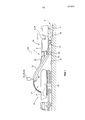
Фиг. 1 представляет собой машину для измельчения с передней загрузкой,FIG. 1 is a front loading grinding machine,
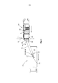
Фиг. 2 представляет собой машину для измельчения с задней загрузкой,FIG. 2 is a rear loading grinding machine,
Фиг. 3 представляет собой вид сверху машины для измельчения в соответствии с фиг. 1.FIG. 3 is a plan view of a grinding machine according to FIG. one.
Фиг. 1 показывает машину для измельчения, используя в качестве примера машину 1а для измельчения с передней загрузкой. Дорожно-строительная машина 1 содержит корпус 2 машины, который поддерживается посредством ходовой части 4, содержащей, например, приводные узлы на гусеничном ходу или колеса, при этом упомянутая ходовая часть 4 соединена с корпусом 2 машины посредством по меньшей мере трех устройств регулирования высоты в виде подъемных колонн 5. Как можно понять из фиг. 2, для данного варианта осуществления предусмотрены четыре подъемные колонны 5, которые могут быть использованы для приведения корпуса 2 машины в заданную плоскость, продолжающуюся преимущественно параллельно поверхности 6 дороги, которая поддерживает приводные узлы на гусеничном ходу ходовой части 4.FIG. 1 shows a grinding machine, using, as an example, a front-
Машина для измельчения дорожного покрытия, показанная на фиг. 1, содержит, в продольном направлении машины 1а для измельчения, рабочий барабан 22 между приводными узлами на гусеничном ходу ходовой части 4.The pavement grinding machine shown in FIG. 1, comprises, in the longitudinal direction of the
Машины 1а, 1b для измельчения могут содержать приводные узлы на гусеничном ходу и/или колеса. Рабочий барабан может быть выполнен с возможностью регулирования по высоте посредством подъемных колонн 5, поддерживающих корпус 2 машины, или относительно корпуса 2 машины.
Другие типы машины 1b для измельчения могут также содержать рабочий барабан 22, например, на высоте задних приводных узлов на гусеничном ходу или колес ходовой части 4.Other types of grinding
Транспортировочное конвейерное устройство с по меньшей мере одним транспортировочным конвейером 11, 12 для удаления измельченного материала может быть также расположено в переднем конце 7 или в заднем конце 8 машины 1а, 1b для измельчения.A conveyor conveyor device with at least one
Фиг. 2 показывает машину 1b для измельчения с задней загрузкой в качестве примера, в котором транспортное средство 10 движется позади машины для измельчения задним ходом.FIG. 2 shows an example of a rear
При наличии достаточного пространства сбоку рядом с машиной 1а, 1b для измельчения, транспортное средство 10 можно также перемещать рядом с машиной 1 для измельчения передним ходом, как показано на фиг. 3.If there is sufficient space at the side next to the grinding
На фиг. 1-3 направления перемещения соответствующих транспортных средств показаны стрелками. In FIG. 1-3 directions of movement of the respective vehicles are shown by arrows.
В варианте осуществления, показанном на фиг. 1, измельченный материал, измельченный посредством рабочего барабана 22, выгружают на загрузочную поверхность 15 транспортного средства 10 посредством первого прочно установленного транспортировочного конвейера 11 транспортировочного конвейерного устройства, который передает измельченный материал 14 на второй поворотный транспортировочный конвейер 12. В результате скорости транспортировочного конвейера 12, измельченный материал 14 не выгружается непосредственно в конце транспортировочного конвейера 12, а перемещается по параболической траектории так, что точка падения 16 на загрузочной поверхности 15 расположена на расстоянии от свободного конца 13 транспортировочного конвейера 12. Транспортировочный конвейер 12 выполнен с возможностью поворота из нейтрального положения влево или вправо посредством узлов 18 поршень-цилиндр, чтобы обеспечить выгрузку измельченного материала 14 на загрузочную поверхность 15 даже при движении на повороте или в случае движения транспортного средства 10 в смещенной колее. Кроме того, водитель транспортного средства машины 1а, 1b для измельчения может регулировать угол возвышения транспортировочного конвейера 12 посредством узла 20 поршень-цилиндр. Угол возвышения, как и скорость подачи транспортировочного конвейера 12, оказывает влияние на параболическую траекторию измельченного материала 14 и на положение точки 16 падения.In the embodiment shown in FIG. 1, the crushed material, crushed by means of the working
Установленный в данный момент угол возвышения относительно горизонтальной первой оси 21 или угол поворота относительно вертикальной второй оси 23 соответственно передаются в систему 24 обнаружения и управления, дополнительно содержащую по меньшей мере один датчик 26, который непрерывно определяет положение загрузочной поверхности 15 и/или последнего или единственного транспортировочного конвейера 12, если смотреть в направлении транспортировки. Упомянутый датчик 26 может быть расположен либо на машине 1а, 1b для измельчения в конце, обращенном к транспортировочному конвейерному устройству, либо в свободном конце 13 транспортировочного конвейера 12. The currently established elevation angle with respect to the horizontal
Система 24 обнаружения и управления может быть встроена в контроллер 3 для осуществления перемещения и измельчения или может быть, как минимум, соединена с упомянутым контроллером, для того чтобы в случае необходимости также получать данные о скорости перемещения и/или зарегистрированном угле рулевого управления машины 1а, 1b для измельчения и скорости подачи транспортировочного конвейера 12. The detection and
Система 24 обнаружения и управления определяет изменяемое положение загрузочной поверхности 15 транспортного средства 10 и последнего или единственного транспортировочного конвейера 12, если смотреть в направлении транспортировки, относительно корпуса 2 машины, и непрерывно и автоматически управляет позиционированием точки 16 падения измельченного материала через угол поворота и/или угол возвышения и/или скорость подачи транспортировочного конвейерного устройства, так что выгружаемый измельченный материал 14 падает, как минимум, в пределах загрузочной поверхности 15. Как вариант, можно также непрерывно определять изменяемое положение загрузочной поверхности 15 транспортного средства 10 относительно последнего или единственного транспортировочного конвейера 12, если смотреть в направлении транспортировки, для того чтобы осуществлять операцию управления. The detection and
Система 24 обнаружения и управления может также выполнять задачу равномерного заполнения загрузочной поверхности 15. Для этой цели может быть предусмотрена программа загрузки для загрузки загрузочной поверхности 15 в соответствии с заданной системой. В данной конструкции, состояние заполнения загрузочной поверхности 15 может быть зарегистрировано и подвергнуто анализу посредством системы записи изображения, для того чтобы непрерывно управлять скоростью подачи и/или положением разгрузочного конца 13 последнего или единственного транспортировочного конвейера 12, если смотреть в направлении транспортировки, относительно загрузочной поверхности 15.The detection and
Управляющие данные для разных положений и/или точек 16 падения могут храниться в карте в соответствии с загрузочными поверхностями 15 разных транспортных средств 10 и/или в соответствии с разными условиями загрузки загрузочной поверхности 15. Такая память в карте может быть встроена в систему 24 обнаружения и управления или в контроллер 3. Управляющие данные относятся к углу поворота, углу возвышения и/или скорости подачи транспортировочного конвейера 12 для разных положений и/или точек 16 падения в пределах положения загрузочной поверхности 15, определяемого посредством системы 24 обнаружения и управления.The control data for different positions and / or points of
Система 24 обнаружения и управления непрерывно определяет положение загрузочной поверхности 15 и/или последнего или единственного транспортировочного конвейера 12, если смотреть в направлении транспортировки, посредством системы 28 записи изображения или неоптической электронной системы позиционирования, которая обеспечивает данные для определения положения загрузочной поверхности 15 относительно корпуса 2 машины или относительно последнего или единственного транспортировочного конвейера 12, если смотреть в направлении транспортировки. Информация, выдаваемая системой 28 записи изображения, может быть подвергнута оценке посредством известных по существу методов анализа изображения. Одним примером неоптической электронной системы позиционирования является система радиочастотной идентификации (RFID), которая дополнительно обеспечивает возможность идентификации конкретной загрузочной поверхности 15 конкретного транспортного средства 10.The detection and
При определении местоположения загрузочной поверхности 15 посредством RFID используются постоянно установленные RFID метки на транспортном средстве 10, в частности на загрузочной поверхности 15.When determining the location of the
При определении местоположения с использованием узлов датчиков Bluetooth в качестве дополнительного неоптического метода определения местоположения, используют узлы датчиков, распределенные в пространстве в качестве меток, и измеряют силу поля сигналов, которая зависит от расстояния.When determining a location using Bluetooth sensor nodes as an additional non-optical method for determining the location, sensor nodes distributed in space as marks are used and the signal field strength, which depends on the distance, is measured.
Само собой разумеется, что можно также использовать комбинацию разных методов определения местоположения.It goes without saying that a combination of different location methods can also be used.
Как правило, можно использовать оптические и квазиоптические (радио) методы измерения длины и угла, а также разные способы измерения времени для разностей времени и разностей времени распространения. Typically, you can use optical and quasi-optical (radio) methods for measuring length and angle, as well as different methods of measuring time for time differences and propagation time differences.
Система 24 обнаружения и управления может сравнивать данные для определения положения с данными заданного положения, для того чтобы, в случае каких-либо отклонений от данных заданного целевого положения, осуществлять непрерывное управление положением разгрузочного конца 13 и/или точки 16 падения измельченного материала 14 и/или управление скоростью подачи. The detection and
Данные целевого положения могут быть определены посредством процесса обучения в том смысле, что положения транспортных средств 1а, 1b, 10 изменяют в соответствии с реалистическими ситуациями, и параметры, требуемые для каждой такой ситуации, а именно угол поворота, угол возвышения и скорость подачи транспортировочного конвейера, сохраняют в памяти. Таким же образом может быть также создана программа загрузки. При этом могут учитываться изменения в управлении, появляющиеся, например, во время движения при повороте. В данном способе данные, считываемые посредством операции считывания, могут также отличаться, если транспортное средство 10 движется слева или справа около колеи измельчения или в колее измельчения машины 1а, 1b для измельчения.The target position data can be determined through the training process in the sense that the positions of the
Claims (26)
Applications Claiming Priority (3)
| Application Number | Priority Date | Filing Date | Title |
|---|---|---|---|
| DE102012215013.7A DE102012215013A1 (en) | 2012-08-23 | 2012-08-23 | Self-propelled milling machine, as well as method for unloading milled material |
| DE102012215013.7 | 2012-08-23 | ||
| PCT/EP2013/067418 WO2014029824A1 (en) | 2012-08-23 | 2013-08-21 | Automotive milling machine, and a method for unloading milled material |
Publications (2)
| Publication Number | Publication Date |
|---|---|
| RU2015109939A RU2015109939A (en) | 2016-10-20 |
| RU2610042C2 true RU2610042C2 (en) | 2017-02-07 |
Family
ID=49029098
Family Applications (1)
| Application Number | Title | Priority Date | Filing Date |
|---|---|---|---|
| RU2015109939A RU2610042C2 (en) | 2012-08-23 | 2013-08-21 | Automatic grinding machine, as well as crushed material unloading method |
Country Status (9)
| Country | Link |
|---|---|
| US (4) | US20150218762A1 (en) |
| EP (2) | EP2888409B1 (en) |
| JP (1) | JP6050493B2 (en) |
| CN (2) | CN103628398B (en) |
| AU (1) | AU2013305023B2 (en) |
| CA (1) | CA2882583C (en) |
| DE (1) | DE102012215013A1 (en) |
| RU (1) | RU2610042C2 (en) |
| WO (1) | WO2014029824A1 (en) |
Families Citing this family (34)
| Publication number | Priority date | Publication date | Assignee | Title |
|---|---|---|---|---|
| DE102013214675A1 (en) | 2013-07-26 | 2015-01-29 | Wirtgen Gmbh | Self-propelled road milling machine, as well as methods for milling and removal of a milled material flow |
| DE102014216603B4 (en) * | 2014-08-21 | 2018-02-22 | Wirtgen Gmbh | Self-propelled milling machine, as well as method for unloading milled material |
| DE102014216713B4 (en) | 2014-08-22 | 2018-09-06 | Wirtgen Gmbh | Self-propelled milling machine, as well as method for unloading milled material |
| DE102014216763B4 (en) | 2014-08-22 | 2018-07-26 | Wirtgen Gmbh | Self-propelled milling machine, as well as method for unloading milled material |
| DE102014012825A1 (en) * | 2014-08-28 | 2016-03-03 | Wirtgen Gmbh | Self-propelled construction machine and method for controlling a self-propelled construction machine |
| US9464391B2 (en) * | 2014-08-29 | 2016-10-11 | Caterpillar Paving Products Inc. | Cold planer having independently controlled conveyors |
| CN104328733B (en) * | 2014-10-20 | 2016-06-15 | 芜湖市泰能电热器具有限公司 | A kind of disintegrating machine |
| CN105692101A (en) * | 2014-11-25 | 2016-06-22 | 无锡市洗选设备厂 | Conveying device for sand washer |
| CN105692098A (en) * | 2014-11-25 | 2016-06-22 | 无锡市洗选设备厂 | Declination signal acquisition type gravel conveying device |
| CN105692099A (en) * | 2014-11-25 | 2016-06-22 | 无锡市洗选设备厂 | Intelligent corner conveying device of sand washing machine |
| CN105692067A (en) * | 2014-11-25 | 2016-06-22 | 无锡市洗选设备厂 | Torsion type corn conveying structure of sand washer |
| CN105692119A (en) * | 2014-11-25 | 2016-06-22 | 无锡市洗选设备厂 | Gravel deviation-rectifying signal acquisition type conveying device |
| CN105692100A (en) * | 2014-11-25 | 2016-06-22 | 无锡市洗选设备厂 | Corner elastic conveying structure of sand washing machine |
| US9938674B2 (en) * | 2015-05-27 | 2018-04-10 | Caterpillar Paving Products Inc. | Cold planer transport payload monitoring system |
| US10380529B2 (en) * | 2015-08-17 | 2019-08-13 | Caterpillar Paving Products Inc. | Cold planer material transport management system |
| PL3165078T3 (en) | 2015-11-06 | 2020-11-02 | Exel Industries | Crop transfer device and corresponding method |
| US9879386B2 (en) * | 2015-12-10 | 2018-01-30 | Caterpillar Paving Products Inc. | System for coordinating milling and paving machines |
| CN108473260B (en) | 2016-01-21 | 2022-08-12 | 维特根有限公司 | System comprising a construction machine, a transport vehicle with a loading space and an image recording device, and method for displaying an image stream during loading or unloading of a transport vehicle |
| DE102016222145A1 (en) | 2016-11-11 | 2018-05-17 | Wirtgen Gmbh | System and method for tracking milled material |
| DE102016223454A1 (en) | 2016-11-25 | 2018-05-30 | Wirtgen Gmbh | System and method for tracking milled material |
| US10927513B2 (en) | 2016-11-11 | 2021-02-23 | Wirtgen Gmbh | System and method for the tracking of milling material |
| DE102016222589B4 (en) | 2016-11-16 | 2020-01-16 | Wirtgen Gmbh | Self-propelled milling machine and method for controlling a self-propelled milling machine |
| DE102017000211A1 (en) | 2017-01-13 | 2018-07-19 | Dynapac Gmbh | Road construction machine and method for operating a road construction machine |
| CN107642023B (en) * | 2017-08-12 | 2020-10-09 | 芜湖习科控制系统有限公司 | Multifunctional conveying device for milling machine |
| DE102017220869A1 (en) | 2017-11-22 | 2019-05-23 | Wirtgen Gmbh | Self-propelled milling machine, method for automatically loading a means of transport with milled material, as well as road or soil treatment unit |
| CN108221610A (en) * | 2018-03-14 | 2018-06-29 | 徐州徐工筑路机械有限公司 | A kind of milling machine automatically transporting materials system of view-based access control model identification |
| US11149407B2 (en) | 2018-12-06 | 2021-10-19 | Caterpillar Inc. | Earth-moving machinery collision threat filtering |
| DE102019104218A1 (en) | 2019-02-19 | 2020-08-20 | Wirtgen Gmbh | Work train, comprising a tillage machine and another vehicle as well as an automated distance monitoring |
| CN110884867B (en) * | 2019-09-05 | 2022-01-14 | 世邦工业科技集团股份有限公司 | Two-dimensional printing type loading system and unloading method |
| US11014753B1 (en) | 2019-11-07 | 2021-05-25 | Caterpillar Paving Products Inc. | Trajectory control of discharge conveyor |
| DE102020001163A1 (en) * | 2020-02-21 | 2021-08-26 | Bomag Gmbh | MATERIAL TRANSFER DEVICE FOR A SOIL MILLING MACHINE AND TILLER WITH SUCH A MATERIAL TRANSFER DEVICE |
| CN111576897B (en) * | 2020-05-15 | 2021-09-21 | 湖北晶骉建设工程有限公司 | Municipal administration pointing device |
| US11845622B2 (en) * | 2020-12-11 | 2023-12-19 | Caterpillar Paving Products Inc. | Truck measurement of a milling machine |
| DE102021114706A1 (en) | 2021-06-08 | 2022-12-08 | Wirtgen Gmbh | Self-propelled milling machine with a machine frame and a conveyor for discharging material |
Citations (4)
| Publication number | Priority date | Publication date | Assignee | Title |
|---|---|---|---|---|
| EP0666018A1 (en) * | 1994-02-08 | 1995-08-09 | CLAAS Kommanditgesellschaft auf Aktien | Device for the automatic loading of containers |
| EP1344445A1 (en) * | 2002-03-13 | 2003-09-17 | Deere & Company | Image processing spout control system |
| DE202007005756U1 (en) * | 2007-04-19 | 2008-08-28 | Wirtgen Gmbh | Self-propelled construction machine |
| RU2394122C1 (en) * | 2006-04-27 | 2010-07-10 | Виртген Гмбх | Machine for road construction, levelling device, as well as control method of depth of milling or inclination of milling of machine for road construction |
Family Cites Families (54)
| Publication number | Priority date | Publication date | Assignee | Title |
|---|---|---|---|---|
| DE155157C (en) | 1904-11-01 | |||
| US3608968A (en) | 1969-04-03 | 1971-09-28 | Christensen Diamond Prod Co | Pavement cutting and water and cutting pickup apparatus |
| US4221434A (en) | 1978-03-23 | 1980-09-09 | Cmi Corporation | Roadway breaker plate for a planar apparatus |
| US4376609A (en) | 1980-03-31 | 1983-03-15 | Sperry Corporation | Automatic spout control for agricultural machines |
| DD155157A1 (en) | 1980-12-09 | 1982-05-19 | Bernd Kaempfe | POSITIONING DEVICE, IN PARTICULAR BETWEEN RE-ESTATE MACHINERY AND TRANSPORT VEHICLES |
| JPS61257118A (en) * | 1985-05-10 | 1986-11-14 | 井関農機株式会社 | Automatic controller of grain lift cylinder in combine |
| EP0245544A3 (en) | 1986-03-11 | 1988-03-23 | Cellutane Co Ltd | Method and apparatus for continuously producing sheet-like products from waste plastics |
| DE3843480A1 (en) | 1988-09-13 | 1990-03-22 | Egon Unterbusch | Mains-independent (grid-independent) sign |
| US4863009A (en) | 1988-11-14 | 1989-09-05 | Alberta Energy Company Ltd. | Control system for an endless belt conveyor train |
| DE19504495A1 (en) | 1995-02-12 | 1996-08-22 | Wirtgen Gmbh | Road surface renewal machine |
| DE19531662A1 (en) * | 1995-08-29 | 1997-03-06 | Claas Ohg | Device for the automatic filling of loading containers |
| JPH0986672A (en) * | 1995-09-25 | 1997-03-31 | San Eng:Kk | Fixed weight loading device |
| DE19628420C2 (en) | 1996-07-15 | 1999-07-29 | Krupp Foerdertechnik Gmbh | Process for material degradation using a bucket wheel excavator |
| DE29617116U1 (en) * | 1996-10-01 | 1996-11-21 | Voegele Ag J | Built-in train |
| JPH1150415A (en) * | 1997-08-04 | 1999-02-23 | Sakai Heavy Ind Ltd | Guidance system of carrying vehicle |
| WO1999052068A1 (en) | 1998-04-03 | 1999-10-14 | Koninklijke Philips Electronics N.V. | Image processing method and system involving contour detection steps |
| DE19848127A1 (en) | 1998-10-19 | 2000-04-20 | Claas Selbstfahr Erntemasch | Device for controlling a transfer device |
| US6682416B2 (en) | 2000-12-23 | 2004-01-27 | Claas Selbstfahrende Erntemaschinen Gmbh | Automatic adjustment of a transfer device on an agricultural harvesting machine |
| DE10203732A1 (en) | 2002-01-30 | 2003-08-21 | Wirtgen Gmbh | Construction machinery |
| DE10357074B3 (en) | 2003-12-04 | 2005-05-19 | Wirtgen Gmbh | Self-propelled road surfacing machine with direct mechanical drive of working roller from drive take-off shaft of internal combustion engine |
| DE102004007716B3 (en) | 2004-02-16 | 2005-06-16 | Wirtgen Gmbh | Road construction asphalt milling machine has dust suction unit located well away from rotating milling tool |
| DE102004011789A1 (en) | 2004-03-09 | 2005-09-29 | Claas Selbstfahrende Erntemaschinen Gmbh | Device for detecting a loading wagon |
| US20060045621A1 (en) | 2004-08-27 | 2006-03-02 | Caterpillar Paving Products Inc. | Asphalt-removing work machine having a storage bin |
| DE102005035480A1 (en) * | 2005-07-26 | 2007-02-01 | Cft Gmbh Compact Filter Technic | Milling machine for road coverings comprises a dust box arranged in front of a ventilator and assigned to a suction channel having an outlet for passing clean waste air directly into the atmosphere |
| FI120191B (en) | 2005-10-03 | 2009-07-31 | Sandvik Tamrock Oy | A method for driving mining vehicles in a mine and a transportation system |
| US7976238B2 (en) | 2006-12-01 | 2011-07-12 | Hall David R | End of a moldboard positioned proximate a milling drum |
| US20080153402A1 (en) * | 2006-12-20 | 2008-06-26 | Christopher Arcona | Roadway grinding/cutting apparatus and monitoring system |
| DE102006062129B4 (en) * | 2006-12-22 | 2010-08-05 | Wirtgen Gmbh | Road construction machine and method for measuring the cutting depth |
| DE102007009666A1 (en) | 2007-02-22 | 2008-08-28 | Carl Zeiss Microimaging Gmbh | Arrangement for filling a container with bulk material |
| US8408838B2 (en) | 2007-03-20 | 2013-04-02 | Volvo Construction Equipment Ab | Milling machine with cutter drum speed control |
| DE102007016670A1 (en) * | 2007-04-04 | 2008-10-09 | Claas Selbstfahrende Erntemaschinen Gmbh | Self-propelled agricultural harvester with controllable transfer device |
| EP2020174B1 (en) * | 2007-08-03 | 2012-02-29 | AGROCOM GmbH & Co. Agrarsystem KG | Agricultural working machine |
| DE102007038677B4 (en) | 2007-08-15 | 2009-09-17 | Wirtgen Gmbh | Scraper device, as well as construction machine |
| DE102008008260B4 (en) | 2008-02-08 | 2010-09-09 | Wirtgen Gmbh | Control of a mining machine and mining machine |
| EP2088196A1 (en) | 2008-02-08 | 2009-08-12 | Boehringer Ingelheim RCV GmbH & Co KG | Methods and devices for producing biomolecules |
| DE102008014001A1 (en) | 2008-03-13 | 2009-09-17 | Claas Selbstfahrende Erntemaschinen Gmbh | Agricultural harvester with a transfer device |
| CN201190259Y (en) * | 2008-04-24 | 2009-02-04 | 镇江华晨华通路面机械有限公司 | Automatic control device of material discharging speed of road milling machine |
| DE102008021484B4 (en) * | 2008-04-29 | 2010-01-28 | Wirtgen Gmbh | Bendable conveyor belt for a construction machine, self-propelled construction machine and method for pivoting a conveyor belt |
| ATE550922T1 (en) * | 2008-06-25 | 2012-04-15 | Claas Agrosystems Gmbh & Co Kg | TRANSMISSION DEVICE AND AGRICULTURAL VEHICLE |
| US8180534B2 (en) * | 2008-09-18 | 2012-05-15 | Deere & Company | Multiple harvester unloading system |
| DE102009008884A1 (en) | 2009-02-14 | 2010-08-26 | Wirtgen Gmbh | Stabilizer or recycler |
| PL2256246T3 (en) | 2009-05-20 | 2018-11-30 | Joseph Vögele AG | Paving machines for applying a cover layer of a road surface |
| EP2301318B1 (en) | 2009-09-07 | 2011-11-16 | CLAAS Agrosystems GmbH & Co. KG | A control system of an agricultural vehicle with a goods carrier, an agricultural vehicle and a method of controlling a goods carrier of the agricultural vehicle |
| PL2311307T3 (en) | 2009-09-07 | 2012-09-28 | Claas E Systems Gmbh | A filling degree gauge, an agricultural vehicle comprising such gauge, and a method of controlling filling of a target area |
| DE102009041842A1 (en) * | 2009-09-18 | 2011-09-01 | Wirtgen Gmbh | Self-propelled road milling machine |
| US10537061B2 (en) * | 2010-02-26 | 2020-01-21 | Cnh Industrial America Llc | System and method for controlling harvest operations |
| US8380401B2 (en) | 2010-06-09 | 2013-02-19 | Cnh America Llc | Automatic grain transfer control system based on real time modeling of a fill level profile for regions of the receiving container |
| WO2012016573A1 (en) | 2010-08-03 | 2012-02-09 | Marini S.P.A. | Guiding system for milling machine mouldboard designed to leave the milled material in a high layer on the milled surface |
| DE102010050831A1 (en) | 2010-11-09 | 2012-05-10 | Bomag Gmbh | Rotor hood for a milling device |
| DE102010043854B4 (en) | 2010-11-12 | 2016-01-14 | Deere & Company | Control arrangement for controlling the transfer of agricultural crop from a harvester to a transport vehicle |
| DE102010051551A1 (en) | 2010-11-18 | 2012-05-24 | Wirtgen Gmbh | Soil cultivation machine and method for milling floors or traffic areas |
| DE102011114183A1 (en) | 2011-09-22 | 2013-03-28 | Bomag Gmbh | Method for controlling a loading process of a transport vehicle with milled material, device for carrying out such a method and milling device |
| DE102011114185A1 (en) | 2011-09-22 | 2013-03-28 | Bomag Gmbh | Work train with a milling device and a transport device with a sensor device for distance monitoring, milling device with a sensor device and method for distance monitoring in a work train |
| DE102012012395A1 (en) | 2012-06-25 | 2014-01-02 | Wirtgen Gmbh | road milling machine |
-
2012
- 2012-08-23 DE DE102012215013.7A patent/DE102012215013A1/en active Pending
-
2013
- 2013-08-21 EP EP13752630.7A patent/EP2888409B1/en active Active
- 2013-08-21 WO PCT/EP2013/067418 patent/WO2014029824A1/en active Application Filing
- 2013-08-21 US US14/422,238 patent/US20150218762A1/en not_active Abandoned
- 2013-08-21 AU AU2013305023A patent/AU2013305023B2/en active Active
- 2013-08-21 CA CA2882583A patent/CA2882583C/en active Active
- 2013-08-21 EP EP17204074.3A patent/EP3342932B1/en active Active
- 2013-08-21 JP JP2015527911A patent/JP6050493B2/en active Active
- 2013-08-21 RU RU2015109939A patent/RU2610042C2/en active
- 2013-08-23 CN CN201310373847.XA patent/CN103628398B/en active Active
- 2013-08-23 CN CN201320520835.0U patent/CN203700926U/en not_active Expired - Lifetime
-
2016
- 2016-01-19 US US15/000,161 patent/US9915043B2/en active Active
-
2018
- 2018-03-07 US US15/913,971 patent/US10400400B2/en active Active
-
2019
- 2019-08-21 US US16/546,949 patent/US10947677B2/en active Active
Patent Citations (4)
| Publication number | Priority date | Publication date | Assignee | Title |
|---|---|---|---|---|
| EP0666018A1 (en) * | 1994-02-08 | 1995-08-09 | CLAAS Kommanditgesellschaft auf Aktien | Device for the automatic loading of containers |
| EP1344445A1 (en) * | 2002-03-13 | 2003-09-17 | Deere & Company | Image processing spout control system |
| RU2394122C1 (en) * | 2006-04-27 | 2010-07-10 | Виртген Гмбх | Machine for road construction, levelling device, as well as control method of depth of milling or inclination of milling of machine for road construction |
| DE202007005756U1 (en) * | 2007-04-19 | 2008-08-28 | Wirtgen Gmbh | Self-propelled construction machine |
Also Published As
| Publication number | Publication date |
|---|---|
| WO2014029824A1 (en) | 2014-02-27 |
| CA2882583C (en) | 2018-03-13 |
| AU2013305023B2 (en) | 2016-11-24 |
| CN103628398A (en) | 2014-03-12 |
| JP2015529762A (en) | 2015-10-08 |
| US20160208447A1 (en) | 2016-07-21 |
| US9915043B2 (en) | 2018-03-13 |
| JP6050493B2 (en) | 2016-12-21 |
| EP3342932B1 (en) | 2021-06-30 |
| US20180258596A1 (en) | 2018-09-13 |
| CA2882583A1 (en) | 2014-02-27 |
| EP3342932A1 (en) | 2018-07-04 |
| CN203700926U (en) | 2014-07-09 |
| RU2015109939A (en) | 2016-10-20 |
| US10400400B2 (en) | 2019-09-03 |
| US20200109528A1 (en) | 2020-04-09 |
| AU2013305023A1 (en) | 2015-03-12 |
| EP2888409B1 (en) | 2017-11-29 |
| US10947677B2 (en) | 2021-03-16 |
| US20150218762A1 (en) | 2015-08-06 |
| DE102012215013A1 (en) | 2014-02-27 |
| CN103628398B (en) | 2017-05-17 |
| EP2888409A1 (en) | 2015-07-01 |
Similar Documents
| Publication | Publication Date | Title |
|---|---|---|
| RU2610042C2 (en) | Automatic grinding machine, as well as crushed material unloading method | |
| RU2631747C2 (en) | Mobile cutting machine and unloading method for milled off material | |
| US9873993B2 (en) | Automotive milling machine, as well as method for steering an automotive milling machine | |
| RU2611802C2 (en) | Self-propelled milling machine and method of milled material unloading | |
| RU2620675C2 (en) | Self-powered milling machine, and the way to remove milled off material |