RU2590890C1 - Electrode for fuel cell and method for fabricating electrode for fuel cell, membrane-electrode assembly, and fuel cell - Google Patents
Electrode for fuel cell and method for fabricating electrode for fuel cell, membrane-electrode assembly, and fuel cell Download PDFInfo
- Publication number
- RU2590890C1 RU2590890C1 RU2015103132/07A RU2015103132A RU2590890C1 RU 2590890 C1 RU2590890 C1 RU 2590890C1 RU 2015103132/07 A RU2015103132/07 A RU 2015103132/07A RU 2015103132 A RU2015103132 A RU 2015103132A RU 2590890 C1 RU2590890 C1 RU 2590890C1
- Authority
- RU
- Russia
- Prior art keywords
- carbon nanotubes
- fuel cell
- electrode
- ionomer
- centers
- Prior art date
Links
Images
Classifications
-
- H—ELECTRICITY
- H01—ELECTRIC ELEMENTS
- H01M—PROCESSES OR MEANS, e.g. BATTERIES, FOR THE DIRECT CONVERSION OF CHEMICAL ENERGY INTO ELECTRICAL ENERGY
- H01M4/00—Electrodes
- H01M4/86—Inert electrodes with catalytic activity, e.g. for fuel cells
- H01M4/90—Selection of catalytic material
- H01M4/92—Metals of platinum group
- H01M4/925—Metals of platinum group supported on carriers, e.g. powder carriers
- H01M4/926—Metals of platinum group supported on carriers, e.g. powder carriers on carbon or graphite
-
- H—ELECTRICITY
- H01—ELECTRIC ELEMENTS
- H01M—PROCESSES OR MEANS, e.g. BATTERIES, FOR THE DIRECT CONVERSION OF CHEMICAL ENERGY INTO ELECTRICAL ENERGY
- H01M4/00—Electrodes
- H01M4/86—Inert electrodes with catalytic activity, e.g. for fuel cells
- H01M4/90—Selection of catalytic material
- H01M4/9075—Catalytic material supported on carriers, e.g. powder carriers
- H01M4/9083—Catalytic material supported on carriers, e.g. powder carriers on carbon or graphite
-
- H—ELECTRICITY
- H01—ELECTRIC ELEMENTS
- H01M—PROCESSES OR MEANS, e.g. BATTERIES, FOR THE DIRECT CONVERSION OF CHEMICAL ENERGY INTO ELECTRICAL ENERGY
- H01M4/00—Electrodes
- H01M4/86—Inert electrodes with catalytic activity, e.g. for fuel cells
- H01M4/88—Processes of manufacture
- H01M4/8825—Methods for deposition of the catalytic active composition
- H01M4/8828—Coating with slurry or ink
-
- H—ELECTRICITY
- H01—ELECTRIC ELEMENTS
- H01M—PROCESSES OR MEANS, e.g. BATTERIES, FOR THE DIRECT CONVERSION OF CHEMICAL ENERGY INTO ELECTRICAL ENERGY
- H01M4/00—Electrodes
- H01M4/86—Inert electrodes with catalytic activity, e.g. for fuel cells
- H01M4/8663—Selection of inactive substances as ingredients for catalytic active masses, e.g. binders, fillers
-
- H—ELECTRICITY
- H01—ELECTRIC ELEMENTS
- H01M—PROCESSES OR MEANS, e.g. BATTERIES, FOR THE DIRECT CONVERSION OF CHEMICAL ENERGY INTO ELECTRICAL ENERGY
- H01M4/00—Electrodes
- H01M4/86—Inert electrodes with catalytic activity, e.g. for fuel cells
- H01M4/88—Processes of manufacture
- H01M4/8878—Treatment steps after deposition of the catalytic active composition or after shaping of the electrode being free-standing body
- H01M4/8882—Heat treatment, e.g. drying, baking
-
- H—ELECTRICITY
- H01—ELECTRIC ELEMENTS
- H01M—PROCESSES OR MEANS, e.g. BATTERIES, FOR THE DIRECT CONVERSION OF CHEMICAL ENERGY INTO ELECTRICAL ENERGY
- H01M4/00—Electrodes
- H01M4/86—Inert electrodes with catalytic activity, e.g. for fuel cells
- H01M4/88—Processes of manufacture
- H01M4/8878—Treatment steps after deposition of the catalytic active composition or after shaping of the electrode being free-standing body
- H01M4/8892—Impregnation or coating of the catalyst layer, e.g. by an ionomer
-
- H—ELECTRICITY
- H01—ELECTRIC ELEMENTS
- H01M—PROCESSES OR MEANS, e.g. BATTERIES, FOR THE DIRECT CONVERSION OF CHEMICAL ENERGY INTO ELECTRICAL ENERGY
- H01M4/00—Electrodes
- H01M4/86—Inert electrodes with catalytic activity, e.g. for fuel cells
- H01M4/88—Processes of manufacture
- H01M4/8878—Treatment steps after deposition of the catalytic active composition or after shaping of the electrode being free-standing body
- H01M4/8896—Pressing, rolling, calendering
-
- H—ELECTRICITY
- H01—ELECTRIC ELEMENTS
- H01M—PROCESSES OR MEANS, e.g. BATTERIES, FOR THE DIRECT CONVERSION OF CHEMICAL ENERGY INTO ELECTRICAL ENERGY
- H01M4/00—Electrodes
- H01M4/86—Inert electrodes with catalytic activity, e.g. for fuel cells
- H01M4/90—Selection of catalytic material
- H01M4/9041—Metals or alloys
-
- H—ELECTRICITY
- H01—ELECTRIC ELEMENTS
- H01M—PROCESSES OR MEANS, e.g. BATTERIES, FOR THE DIRECT CONVERSION OF CHEMICAL ENERGY INTO ELECTRICAL ENERGY
- H01M4/00—Electrodes
- H01M4/86—Inert electrodes with catalytic activity, e.g. for fuel cells
- H01M4/96—Carbon-based electrodes
-
- H—ELECTRICITY
- H01—ELECTRIC ELEMENTS
- H01M—PROCESSES OR MEANS, e.g. BATTERIES, FOR THE DIRECT CONVERSION OF CHEMICAL ENERGY INTO ELECTRICAL ENERGY
- H01M8/00—Fuel cells; Manufacture thereof
- H01M8/10—Fuel cells with solid electrolytes
- H01M8/1004—Fuel cells with solid electrolytes characterised by membrane-electrode assemblies [MEA]
-
- H—ELECTRICITY
- H01—ELECTRIC ELEMENTS
- H01M—PROCESSES OR MEANS, e.g. BATTERIES, FOR THE DIRECT CONVERSION OF CHEMICAL ENERGY INTO ELECTRICAL ENERGY
- H01M8/00—Fuel cells; Manufacture thereof
- H01M8/10—Fuel cells with solid electrolytes
- H01M2008/1095—Fuel cells with polymeric electrolytes
-
- H—ELECTRICITY
- H01—ELECTRIC ELEMENTS
- H01M—PROCESSES OR MEANS, e.g. BATTERIES, FOR THE DIRECT CONVERSION OF CHEMICAL ENERGY INTO ELECTRICAL ENERGY
- H01M2300/00—Electrolytes
- H01M2300/0017—Non-aqueous electrolytes
- H01M2300/0065—Solid electrolytes
- H01M2300/0082—Organic polymers
-
- Y—GENERAL TAGGING OF NEW TECHNOLOGICAL DEVELOPMENTS; GENERAL TAGGING OF CROSS-SECTIONAL TECHNOLOGIES SPANNING OVER SEVERAL SECTIONS OF THE IPC; TECHNICAL SUBJECTS COVERED BY FORMER USPC CROSS-REFERENCE ART COLLECTIONS [XRACs] AND DIGESTS
- Y02—TECHNOLOGIES OR APPLICATIONS FOR MITIGATION OR ADAPTATION AGAINST CLIMATE CHANGE
- Y02E—REDUCTION OF GREENHOUSE GAS [GHG] EMISSIONS, RELATED TO ENERGY GENERATION, TRANSMISSION OR DISTRIBUTION
- Y02E60/00—Enabling technologies; Technologies with a potential or indirect contribution to GHG emissions mitigation
- Y02E60/30—Hydrogen technology
- Y02E60/50—Fuel cells
-
- Y—GENERAL TAGGING OF NEW TECHNOLOGICAL DEVELOPMENTS; GENERAL TAGGING OF CROSS-SECTIONAL TECHNOLOGIES SPANNING OVER SEVERAL SECTIONS OF THE IPC; TECHNICAL SUBJECTS COVERED BY FORMER USPC CROSS-REFERENCE ART COLLECTIONS [XRACs] AND DIGESTS
- Y02—TECHNOLOGIES OR APPLICATIONS FOR MITIGATION OR ADAPTATION AGAINST CLIMATE CHANGE
- Y02P—CLIMATE CHANGE MITIGATION TECHNOLOGIES IN THE PRODUCTION OR PROCESSING OF GOODS
- Y02P70/00—Climate change mitigation technologies in the production process for final industrial or consumer products
- Y02P70/50—Manufacturing or production processes characterised by the final manufactured product
Landscapes
- Chemical & Material Sciences (AREA)
- Chemical Kinetics & Catalysis (AREA)
- Electrochemistry (AREA)
- General Chemical & Material Sciences (AREA)
- Engineering & Computer Science (AREA)
- Manufacturing & Machinery (AREA)
- Materials Engineering (AREA)
- Sustainable Development (AREA)
- Life Sciences & Earth Sciences (AREA)
- Sustainable Energy (AREA)
- Physics & Mathematics (AREA)
- Thermal Sciences (AREA)
- Inert Electrodes (AREA)
- Carbon And Carbon Compounds (AREA)
- Composite Materials (AREA)
- Fuel Cell (AREA)
Abstract
Description
Область техникиTechnical field
[0001] Настоящее изобретение касается электрода, используемого в топливном элементе.[0001] The present invention relates to an electrode used in a fuel cell.
Уровень техникиState of the art
[0002] Известный топливный элемент использует углеродные нанотрубки (УНТ) для электродов (например, патентная литература 1). Патентная литература 1 раскрывает топливный элемент, содержащий волокнистый проводящий носитель, катализатор, нанесенный на поверхность волокнистого проводящего носителя и твердый полимерный электролит, покрывающий поверхность этого катализатора. Когда R (нм) обозначает радиус волокна волокнистого проводящего носителя, А (штук/нм2) обозначает плотность волокон волокнистого проводящего носителя на единицу площади электрода, а L (нм) обозначает длину волокна волокнистого проводящего носителя, электрод для топливного элемента задан так, чтобы удовлетворять следующим четырем выражениям:[0002] A known fuel cell uses carbon nanotubes (CNTs) for electrodes (for example, Patent Literature 1).
R>1 нмR> 1 nm
L<20000 нмL <20,000 nm
1-АπR2>0,51-AπR 2 > 0.5
2πRLA>2002πRLA> 200
Список цитированияCitation list
Патентная литератураPatent Literature
[0003] [PTL1] JP2009-140764 A[0003] [PTL1] JP2009-140764 A
Сущность изобретенияSUMMARY OF THE INVENTION
Техническая проблемаTechnical problem
[0004] Структура предшествующего уровня техники, однако, имеет небольшое число мест на углеродных нанотрубках, где нанесен металлический катализатор. Это уменьшает количество нанесенного металлического катализатора и вызывает проблему недостаточной выходной мощности. Возможной мерой увеличения числа мест на углеродных нанотрубках, где нанесен металлический катализатор, может быть увеличение длины углеродных нанотрубок или увеличение численной плотности углеродных нанотрубок (число углеродных нанотрубок на единицу площади). Избыточное увеличение длины углеродных нанотрубок или избыточное увеличение численной плотности углеродных нанотрубок может, однако, делать углеродные нанотрубки подобными тому, чтобы быть спрессованными и блокирующими газовую диффузию слоями в пакете топливных элементов, и может ухудшать коэффициент диффузии газа или дренаж, чтобы уменьшить напряжение. Избыточное увеличение может также быть причиной того, что углеродные нанотрубки не будут сжаты при приложении нагрузки, и увеличивать расстояние между электролитной мембраной и катализатором для топливного элемента, где происходит генерация энергии, ухудшая, таким образом, протонную проводимость, снижая напряжение. В результате особого исследования в различных условиях изобретатели настоящей заявки обнаружили, что характеристики генерации энергии топливного элемента улучшаются при определенном соотношении шага между центрами (или плотности на единицу площади) и длины углеродных нанотрубок. По отношению к топливному элементу, использующему углеродные нанотрубки для электродов, изобретатели также обнаружили, что использование электрода с углеродными нанотрубками имеет лучший эффект увеличенной растворимости кислорода в иономере, чем использование электрода с углеродными частицами.[0004] The structure of the prior art, however, has a small number of spots on carbon nanotubes where a metal catalyst is supported. This reduces the amount of supported metal catalyst and causes the problem of insufficient power output. A possible measure of increasing the number of spots on carbon nanotubes where a metal catalyst is deposited may be to increase the length of carbon nanotubes or increase the numerical density of carbon nanotubes (the number of carbon nanotubes per unit area). An excess increase in the length of carbon nanotubes or an increase in the numerical density of carbon nanotubes can, however, make carbon nanotubes similar to being compressed and blocking gas diffusion layers in a fuel cell stack, and can degrade gas diffusion or drainage to reduce stress. Excessive increase can also cause carbon nanotubes to not be compressed when a load is applied, and increase the distance between the electrolyte membrane and the catalyst for the fuel cell, where energy is generated, thereby deteriorating proton conductivity, and reducing voltage. As a result of a special study under various conditions, the inventors of the present application found that the characteristics of energy generation of a fuel cell improve with a certain ratio of the step between the centers (or density per unit area) and the length of the carbon nanotubes. With respect to a fuel cell using carbon nanotubes for electrodes, the inventors also found that using an electrode with carbon nanotubes has a better effect of increased oxygen solubility in an ionomer than using an electrode with carbon particles.
Решение проблемыSolution
[0005] Чтобы достичь, по меньшей мере, части вышесказанного, настоящее изобретение обеспечивает различные аспекты, описанные ниже.[0005] In order to achieve at least part of the above, the present invention provides various aspects described below.
[0006] (1) Согласно одному аспекту данного изобретения обеспечивается электрод для топливного элемента. Этот электрод для топливного элемента содержит: углеродные нанотрубки; катализатор для топливного элемента, нанесенный на углеродные нанотрубки; и иономер, обеспеченный так, чтобы покрывать углеродные нанотрубки и катализатор для топливного элемента, причем, если длина углеродных нанотрубок обозначена как La [мкм], а шаг между центрами углеродных нанотрубок обозначен как Ра [нм], то длина La и шаг Ра между центрами удовлетворяют двум выражениям, приведенным ниже: 30≤La≤240; и 0,351×La+75≤Ра≤250. Даже когда топливный элемент, включающий в себя этот электрод для топливного элемента, сжат в результате приложении нагрузки, электрод для топливного элемента этого аспекта делает, чтобы поры между углеродными нанотрубками были блокированы с меньшей вероятностью, и подавляет ухудшение коэффициента диффузии газа или дренажа полученной воды, улучшая, таким образом, характеристики генерации энергии. Это также поддерживает достаточно малое расстояние между электролитной мембраной и катализатором для топливного элемента, где происходит генерация энергии и, таким образом, гарантирует хорошую протонную проводимость.[0006] (1) According to one aspect of the present invention, an electrode for a fuel cell is provided. This fuel cell electrode contains: carbon nanotubes; a catalyst for a fuel cell deposited on carbon nanotubes; and an ionomer provided to cover the carbon nanotubes and the catalyst for the fuel cell, wherein if the length of the carbon nanotubes is indicated as La [μm] and the pitch between the centers of the carbon nanotubes is designated Pa [nm], then the length La and the pitch Pa between the centers satisfy the two expressions below: 30≤La≤240; and 0.351 × La + 75≤Pa≤250. Even when the fuel cell including this electrode for the fuel cell is compressed by applying a load, the electrode for the fuel cell of this aspect makes the pores between the carbon nanotubes less likely to block and suppresses deterioration of the gas diffusion coefficient or the drainage of the produced water, thus improving energy generation characteristics. It also maintains a sufficiently small distance between the electrolyte membrane and the catalyst for the fuel cell, where energy is generated and, thus, guarantees good proton conductivity.
[0007] (2) Электрод для топливного элемента согласно вышеприведенному аспекту, причем длина La и шаг Ра между центрами могут удовлетворять выражению, приведенному ниже: 0,708×La+59,3≤Ра≤250. Электрод для топливного элемента этого аспекта дополнительно улучшает характеристики генерации энергии топливного элемента.[0007] (2) An electrode for a fuel cell according to the above aspect, wherein the length La and the pitch Pa between centers can satisfy the expression below: 0.708 × La + 59.3 ≤ Pa 2 250. The electrode for the fuel cell of this aspect further improves the energy generation characteristics of the fuel cell.
[0008] (3) Электрод для топливного элемента согласно вышеприведенным аспектам, причем длина La и шаг Ра между центрами могут удовлетворять выражению, приведенному ниже: 30≤La≤210 и 0,611×La+82,5≤Ра≤1,333×La+190. Топливные элементы, использующие этот электрод для топливного элемента, уложены в стопку и сжаты при приложении нагрузки. Электрод для топливного элемента этого аспекта сокращает расстояние между электролитной мембраной и катализатором для топливного элемента, где происходит генерация энергии в результате сжатия. Это поддерживает хорошую протонную проводимость от электролитной мембраны через иономер в электроде к катализатору для топливного элемента и, тем самым, улучшает характеристики генерации энергии топливного элемента.[0008] (3) An electrode for a fuel cell according to the above aspects, the length La and the pitch Pa between the centers can satisfy the expression below: 30≤La≤210 and 0.611 × La + 82.5≤Pa≤1,333 × La + 190 . Fuel cells using this electrode for a fuel cell are stacked and compressed when a load is applied. An electrode for a fuel cell of this aspect shortens the distance between the electrolyte membrane and the catalyst for the fuel cell, where compression energy is generated. This maintains good proton conductivity from the electrolyte membrane through the ionomer in the electrode to the catalyst for the fuel cell, and thereby improves the energy generation characteristics of the fuel cell.
[0009] (4) Электрод для топливного элемента согласно вышеприведенным аспектам, причем длина La и шаг Ра между центрами могут удовлетворять выражению, приведенному ниже: 0,78×La+78≤Ра≤1,333×La+150. Электрод для топливного элемента этого аспекта дополнительно улучшает характеристики генерации энергии топливного элемента.[0009] (4) An electrode for a fuel cell according to the above aspects, the length La and the pitch Pa between centers can satisfy the expression below: 0.78 × La + 78≤Pa≤1,333 × La + 150. The electrode for the fuel cell of this aspect further improves the energy generation characteristics of the fuel cell.
[0010] (5) Согласно одному аспекту данного изобретения обеспечивается электрод для топливного элемента. Этот электрод для топливного элемента содержит: углеродные нанотрубки; катализатор для топливного элемента, нанесенный на углеродные нанотрубки; и иономер, обеспеченный так, чтобы покрывать углеродные нанотрубки и катализатор для топливного элемента, причем, если длина углеродных нанотрубок обозначена как La [мкм], а численная плотность углеродных нанотрубок обозначена как Nd [штук/м2], то длина La и численная плотность углеродных нанотрубок Nd удовлетворяют двум выражениям, приведенным ниже: 30≤La≤240; и 1,7×10¹³≤Nd≤1×10¹⁸/(0,351×La+75)2. Даже когда топливный элемент, включающий в себя этот электрод для топливного элемента, сжат в результате приложения нагрузки, электрод для топливного элемента этого аспекта делает, чтобы поры между углеродными нанотрубками были блокированы с меньшей вероятностью, и подавляет ухудшение коэффициента диффузии газа или дренажа полученной воды, улучшая, таким образом, характеристики генерации энергии.[0010] (5) According to one aspect of the present invention, an electrode for a fuel cell is provided. This fuel cell electrode contains: carbon nanotubes; a catalyst for a fuel cell deposited on carbon nanotubes; and an ionomer provided to cover the carbon nanotubes and the catalyst for the fuel cell, wherein if the length of the carbon nanotubes is indicated as La [μm] and the numerical density of the carbon nanotubes is indicated as Nd [units / m 2 ], then the length La and the numerical density carbon nanotubes Nd satisfy the two expressions below: 30≤La≤240; and 1.7 × 10 13 ≤Nd≤1 × 10 18 / (0.351 × La + 75) 2 . Even when the fuel cell including this electrode for the fuel cell is compressed by applying a load, the electrode for the fuel cell of this aspect makes the pores between the carbon nanotubes less likely to block, and suppresses the deterioration of the gas diffusion coefficient or the drainage of the produced water, thus improving energy generation characteristics.
[0011] (6) Электрод для топливного элемента согласно вышеприведенным аспектам, причем электрод для топливного элемента, содержащий нанотрубки, может быть соединен с электролитной мембраной путем термического давления и затем быть сжат до толщины не менее чем 5 [мкм] и не более чем 20 [мкм], чтобы быть использованным в качестве катализатора для топливного элемента. Электрод для топливного элемента этого аспекта обеспечивает как хороший коэффициент диффузии газа, так и хорошую протонную проводимость, и, таким образом, улучшает характеристики генерации энергии топливного элемента.[0011] (6) An electrode for a fuel cell according to the above aspects, wherein the electrode for a fuel cell containing nanotubes can be connected to the electrolyte membrane by thermal pressure and then compressed to a thickness of not less than 5 [μm] and not more than 20 [μm] to be used as a catalyst for a fuel cell. An electrode for a fuel cell of this aspect provides both a good gas diffusion coefficient and good proton conductivity, and thus improves the energy generation characteristics of the fuel cell.
[0012] (7) Электрод для топливного элемента согласно вышеприведенным аспектам, причем электрод для топливного элемента, содержащий нанотрубки, может быть соединен с электролитной мембраной посредством термического давления и затем быть сжат до толщины не менее 7,5 [мкм] и не более чем 17,5 [мкм], чтобы быть использованным в качестве катализатора для топливного элемента. Электрод для топливного элемента этого аспекта обеспечивает как хороший коэффициент диффузии газа, так и хорошую протонную проводимость, и, таким образом, улучшает характеристики генерации энергии топливного элемента.[0012] (7) An electrode for a fuel cell according to the above aspects, wherein the electrode for a fuel cell containing nanotubes can be connected to the electrolyte membrane by thermal pressure and then be compressed to a thickness of not less than 7.5 [μm] and not more than 17.5 [μm] to be used as a catalyst for a fuel cell. An electrode for a fuel cell of this aspect provides both a good gas diffusion coefficient and good proton conductivity, and thus improves the energy generation characteristics of the fuel cell.
[0013] (8) Электрод для топливного элемента согласно вышеприведенным аспектам, причем иономер может покрывать углеродные нанотрубки толщиной не менее чем 2,5 [нм] и не более чем 15 [нм]. Электрод для топливного элемента этого аспекта не мешает переносу кислорода через иономер к поверхности катализатора для топливного элемента и поддерживает высокую концентрацию кислорода поблизости от катализатора, сохраняя, в то же время, хорошую протонную проводимость, улучшая, таким образом, характеристики генерации энергии топливного элемента.[0013] (8) An electrode for a fuel cell according to the above aspects, wherein the ionomer can cover carbon nanotubes with a thickness of not less than 2.5 [nm] and not more than 15 [nm]. The electrode for the fuel cell of this aspect does not interfere with the transfer of oxygen through the ionomer to the surface of the catalyst for the fuel cell and maintains a high concentration of oxygen in the vicinity of the catalyst, while maintaining good proton conductivity, thereby improving the energy generation characteristics of the fuel cell.
[0014] (9) Электрод для топливного элемента согласно вышеприведенным аспектам, причем иономер может покрывать углеродные нанотрубки толщиной не менее чем 5 [нм] и не более чем 12,5 [нм]. Электрод для топливного элемента этого аспекта дополнительно улучшает характеристики генерации энергии топливного элемента.[0014] (9) An electrode for a fuel cell according to the above aspects, wherein the ionomer can cover carbon nanotubes with a thickness of not less than 5 [nm] and not more than 12.5 [nm]. The electrode for the fuel cell of this aspect further improves the energy generation characteristics of the fuel cell.
[0015] (10) Электрод для топливного элемента согласно вышеприведенным аспектам, причем [масса иономера]/[масса углеродных нанотрубок], что представляет собой отношение массы иономера к массе углеродных нанотрубок, может быть не меньше чем 0,5 и не больше чем 3,0. Электрод для топливного элемента этого аспекта улучшает характеристики генерации энергии топливного элемента.[0015] (10) An electrode for a fuel cell according to the above aspects, wherein [mass of ionomer] / [mass of carbon nanotubes], which is the ratio of mass of ionomer to mass of carbon nanotubes, can be no less than 0.5 and not more than 3 , 0. The fuel cell electrode of this aspect improves the energy generation characteristics of the fuel cell.
[0016] (11) Электрод для топливного элемента согласно вышеприведенным аспектам, причем [масса иономера]/[масса углеродных нанотрубок] может быть не меньше чем 1,0 и не больше чем 2,5. Электрод для топливного элемента этого аспекта дополнительно улучшает характеристики генерации энергии топливного элемента.[0016] (11) An electrode for a fuel cell according to the above aspects, wherein the [mass of ionomer] / [mass of carbon nanotubes] can be not less than 1.0 and not more than 2.5. The electrode for the fuel cell of this aspect further improves the energy generation characteristics of the fuel cell.
[0017] (12) Электрод для топливного элемента согласно вышеприведенным аспектам, причем иономер может иметь растворимость кислорода, которая выше чем 10,9 моль/дм3. Электрод для топливного элемента этого аспекта имеет короткое расстояние между поверхностью иономера и катализатором для топливного элемента. Соответственно, увеличение растворимости кислорода в иономере увеличивает приток кислорода к катализатору для топливного элемента и улучшает характеристики генерации энергии топливного элемента.[0017] (12) An electrode for a fuel cell according to the above aspects, wherein the ionomer may have an oxygen solubility that is higher than 10.9 mol / dm 3 . The electrode for the fuel cell of this aspect has a short distance between the surface of the ionomer and the catalyst for the fuel cell. Accordingly, increasing the solubility of oxygen in the ionomer increases the oxygen flow to the catalyst for the fuel cell and improves the energy generation characteristics of the fuel cell.
[0018] (13) Электрод для топливного элемента согласно вышеприведенным аспектам, причем иономер может иметь растворимость кислорода, которая равна или выше чем 20 моль/дм3. Электрод для топливного элемента этого аспекта дополнительно улучшает характеристики генерации энергии топливного элемента.[0018] (13) An electrode for a fuel cell according to the above aspects, wherein the ionomer may have an oxygen solubility that is equal to or higher than 20 mol / dm 3 . The electrode for the fuel cell of this aspect further improves the energy generation characteristics of the fuel cell.
[0019] (14) Согласно одному аспекту этого изобретения обеспечивается способ изготовления электрода для топливного элемента. Способ изготовления электрода для топливного элемента содержит: получение того, чтобы углеродные нанотрубки росли на подложке, так что, если длина углеродных нанотрубок обозначена как La [мкм], а шаг между центрами углеродных нанотрубок обозначен как Ра [нм], то длина La и шаг Ра между центрами удовлетворяют двум выражениям, приведенным ниже: 30≤La≤240; и 0,351×La+75≤Ра≤250; получение катализатора для топливного элемента, нанесенного на углеродные нанотрубки; покрытие углеродных нанотрубок иономером; и соединение углеродных нанотрубок с электролитной мембраной путем приложения термического давления для формирования первого слоя катализатора. В топливном элементе, включающем в себя электрод для топливного элемента, изготовленный с помощью способа изготовления электрода для топливного элемента данного аспекта, углеродные нанотрубки имеют равномерное тонкое покрытие из иономера. Даже когда топливный элемент сжат в результате приложения нагрузки, эта конфигурация делает, чтобы поры между углеродными нанотрубками в первом слое катализатора были блокированы с меньшей вероятностью, и подавляет ухудшение коэффициента диффузии газа или дренажа полученной воды, улучшая, таким образом, характеристики генерации энергии.[0019] (14) According to one aspect of this invention, a method for manufacturing an electrode for a fuel cell is provided. A method for manufacturing an electrode for a fuel cell comprises: making carbon nanotubes grow on a substrate, so that if the length of the carbon nanotubes is indicated as La [μm] and the step between the centers of the carbon nanotubes is indicated as Pa [nm], then the length of La and the step Ra between the centers satisfy the two expressions below: 30≤La≤240; and 0.351 × La + 75≤Pa≤250; obtaining a catalyst for a fuel cell deposited on carbon nanotubes; coating of carbon nanotubes with an ionomer; and connecting carbon nanotubes to an electrolyte membrane by applying thermal pressure to form a first catalyst layer. In a fuel cell including an electrode for a fuel cell manufactured by a method of manufacturing an electrode for a fuel cell of this aspect, carbon nanotubes have a uniformly thin ionomer coating. Even when the fuel cell is compressed by applying a load, this configuration makes the pores between the carbon nanotubes in the first catalyst bed less likely to be blocked and suppresses the deterioration of the gas diffusion coefficient or the drainage of the produced water, thereby improving energy generation characteristics.
[0020] (15) Согласно одному аспекту данного изобретения обеспечивается способ изготовления электрода для топливного элемента. Способ изготовления электрода для топливного элемента содержит: выращивание углеродных нанотрубок на подложке, так что, если длина углеродных нанотрубок обозначена как La [мкм], а численная плотность углеродных нанотрубок обозначена как Nd [штук/м2], как длина La и численная плотность углеродных нанотрубок Nd удовлетворяют двум выражениям, приведенным ниже: 30≤La≤240; и 1,7×10¹³≤Nd≤1×10¹⁸/(0,351×La+75)2; получение катализатора для топливного элемента, нанесенного на углеродные нанотрубки; покрытие углеродных нанотрубок иономером; и соединение углеродных нанотрубок с электролитной мембраной путем приложения термического давления для формирования первого слоя катализатора. В топливном элементе, включающем в себя электрод для топливного элемента, изготовленном с помощью способа изготовления электрода для топливного элемента этого аспекта, углеродные нанотрубки имеют равномерное тонкое покрытие из иономера. Даже когда топливный элемент сжат в результате приложения нагрузки, эта конфигурация делает, чтобы поры между углеродными нанотрубками в первом слое катализатора были блокированы с меньшей вероятностью, и подавляет ухудшение коэффициента диффузии газа или дренажа полученной воды, улучшая, таким образом, характеристики генерации энергии.[0020] (15) According to one aspect of the present invention, there is provided a method of manufacturing an electrode for a fuel cell. A method for manufacturing an electrode for a fuel cell comprises: growing carbon nanotubes on a substrate, so that if the length of the carbon nanotubes is indicated as La [μm], and the numerical density of carbon nanotubes is indicated as Nd [pieces / m 2 ], as the length La and the numerical density of carbon Nd nanotubes satisfy the two expressions below: 30≤La≤240; and 1.7 × 10 13 ≤Nd≤1 × 10 18 / (0.351 × La + 75) 2 ; obtaining a catalyst for a fuel cell deposited on carbon nanotubes; coating of carbon nanotubes with an ionomer; and connecting carbon nanotubes to an electrolyte membrane by applying thermal pressure to form a first catalyst layer. In a fuel cell including an electrode for a fuel cell manufactured by a method of manufacturing an electrode for a fuel cell of this aspect, carbon nanotubes have a uniformly thin ionomer coating. Even when the fuel cell is compressed by applying a load, this configuration makes the pores between the carbon nanotubes in the first catalyst bed less likely to be blocked and suppresses the deterioration of the gas diffusion coefficient or the drainage of the produced water, thereby improving energy generation characteristics.
[0021] (16) Согласно одному аспекту этого изобретения обеспечивается способ изготовления мембранно-электродного узла. Данный способ изготовления мембранно-электродного узла содержит: изготовление электрода для топливного элемента с помощью способа изготовления согласно вышеприведенным аспектам; и накладывание и высушивание каталитической краски на противоположной поверхности электролитной мембраны, которая находится на противоположной стороне к поверхности электролитной мембраны, соединенной с углеродными нанотрубками, чтобы сформировать второй слой катализатора. В топливном элементе, включающем в себя электрод для топливного элемента, изготовленный с помощью способа производства мембранно-электродного узла этого аспекта, даже когда топливный элемент сжат в результате приложения нагрузки, эта конфигурация делает, чтобы поры между углеродными нанотрубками в первом слое катализатора были блокированы с меньшей вероятностью, и подавляет ухудшение коэффициента диффузии газа или дренажа полученной воды, улучшая, таким образом, характеристики генерации энергии.[0021] (16) According to one aspect of this invention, a method of manufacturing a membrane electrode assembly is provided. This method of manufacturing a membrane-electrode assembly comprises: manufacturing an electrode for a fuel cell using a manufacturing method according to the above aspects; and applying and drying the catalytic paint on the opposite surface of the electrolyte membrane, which is on the opposite side to the surface of the electrolyte membrane connected to carbon nanotubes, to form a second catalyst layer. In a fuel cell including an electrode for a fuel cell manufactured by a method of manufacturing a membrane electrode assembly of this aspect, even when the fuel cell is compressed by applying a load, this configuration makes the pores between the carbon nanotubes in the first catalyst layer blocked less likely, and suppresses the deterioration of the diffusion coefficient of the gas or drainage of the obtained water, thereby improving energy generation characteristics.
[0022] (17) Согласно одному аспекту данного изобретения обеспечивается способ изготовления топливного элемента. Данный способ изготовления топливного элемента содержит: формирование мембранно-электродного узла с помощью способа производства согласно вышеприведенному аспекту; формирование рамы на внешней периферии мембранно-электродного узла; размещение газодиффузионных слоев на внутренней стороне этой рамы на обеих поверхностях мембранно-электродного узла; размещение разделительных пластин на внешних поверхностях газодиффузионных слоев, чтобы изготовить единичный элемент; и укладывание в стопку единичных элементов и приложение нагрузки к уложенным в стопку единичным элементам, так что первый слой катализатора сжат до толщины не меньше чем 5 [мкм] и не больше чем 20 [мкм]. Способ производства топливного элемента данного аспекта сокращает расстояние между электролитной мембраной и катализатором для топливного элемента, где происходит генерация энергии. Это поддерживает хорошую протонную проводимость от электролитной мембраны через иономер к катализатору для топливного элемента и, тем самым, улучшает характеристики генерации энергии топливного элемента. Кроме того, в случае укладывания в стопку топливных элементов эта конфигурация делает, чтобы поры между углеродными нанотрубками в первом слое катализатора были блокированы с меньшей вероятностью, и подавляет ухудшение коэффициента диффузии газа или дренажа полученной воды, улучшая, таким образом, характеристики генерации энергии.[0022] (17) According to one aspect of the present invention, a method for manufacturing a fuel cell is provided. This method of manufacturing a fuel cell comprises: forming a membrane-electrode assembly using a manufacturing method according to the above aspect; frame formation on the outer periphery of the membrane-electrode assembly; placing gas diffusion layers on the inside of this frame on both surfaces of the membrane-electrode assembly; placing dividing plates on the outer surfaces of the gas diffusion layers to make a single element; and stacking the unit cells and applying a load to the stacked unit cells, so that the first catalyst layer is compressed to a thickness of not less than 5 [μm] and not more than 20 [μm]. The fuel cell manufacturing method of this aspect reduces the distance between the electrolyte membrane and the fuel cell catalyst where energy is generated. This maintains good proton conductivity from the electrolyte membrane through the ionomer to the catalyst for the fuel cell, and thereby improves the energy generation characteristics of the fuel cell. In addition, in the case of stacking fuel cells, this configuration makes the pores between the carbon nanotubes in the first catalyst bed less likely to block and suppresses the deterioration of the gas diffusion coefficient or the drainage of the resulting water, thereby improving energy generation characteristics.
[0023] Данное изобретение может быть реализовано с помощью различных аспектов. Данное изобретение может быть реализовано с помощью любого из различных аспектов, иных чем электрод для топливного элемента, например, мембранно-электродного узла, топливного элемента, способа изготовления электрода для топливного элемента, способа производства мембранно-электродного узла и способа изготовления топливного элемента.[0023] The present invention can be implemented using various aspects. The present invention can be implemented using any of various aspects other than an electrode for a fuel cell, for example, a membrane-electrode assembly, a fuel cell, a method for manufacturing an electrode for a fuel cell, a method for manufacturing a membrane-electrode assembly, and a method for manufacturing a fuel cell.
Краткое описание чертежейBrief Description of the Drawings
[0024] Фиг. 1 представляет собой графическое изображение, иллюстрирующее общую конфигурацию топливного элемента согласно одному варианту осуществления данного изобретения.[0024] FIG. 1 is a graphical illustration illustrating a general configuration of a fuel cell according to one embodiment of the present invention.
Фиг. 2 представляет собой графическое изображение, иллюстрирующее способ изготовления мембранно-электродного узла.FIG. 2 is a graphical illustration illustrating a manufacturing method of a membrane electrode assembly.
Фиг. 3 представляет собой графическое изображение, схематично иллюстрирующее кремниевую подложку, на которой выращены углеродные нанотрубки, наблюдаемое при помощи микроскопа на виде сверху.FIG. 3 is a graphical representation schematically illustrating a silicon substrate on which carbon nanotubes are grown, observed with a microscope in a plan view.
Фиг. 4 представляет собой графическое изображение, схематично иллюстрирующее кремниевую подложку, на которой выращены углеродные нанотрубки, наблюдаемое при помощи микроскопа сбоку.FIG. 4 is a graphical representation schematically illustrating a silicon substrate on which carbon nanotubes are grown, observed with a side microscope.
Фиг. 5 представляет собой графическое изображение, схематично иллюстрирующее процедуру определения степени кривизны τ углеродных нанотрубок.FIG. 5 is a graphical diagram schematically illustrating a procedure for determining the degree of curvature τ of carbon nanotubes.
Фиг. 6 представляет собой графическое изображение, схематично иллюстрирующее топливный элемент для измерения характеристик генерации энергии.FIG. 6 is a graphical diagram schematically illustrating a fuel cell for measuring power generation characteristics.
Фиг. 7 представляет собой график, показывающий результаты оценки характеристик генерации энергии, когда толщина слоя углеродного катализатора сжата до 20 [мкм].FIG. 7 is a graph showing the results of evaluating energy generation characteristics when the thickness of the carbon catalyst layer is compressed to 20 [μm].
Фиг. 8 представляет собой график, показывающий результаты оценки характеристик генерации энергии, когда толщина слоя углеродного катализатора сжата до 15 [мкм].FIG. 8 is a graph showing the results of evaluating energy generation characteristics when the thickness of the carbon catalyst layer is compressed to 15 [μm].
Фиг. 9 представляет собой график, показывающий результаты оценивания характеристик генерации энергии, когда толщина слоя углеродного катализатора сжата до 10 [мкм].FIG. 9 is a graph showing the results of evaluating energy generation characteristics when the thickness of the carbon catalyst layer is compressed to 10 [μm].
Фиг. 10 представляет собой график, показывающий результаты оценивания характеристик генерации энергии, когда толщина слоя углеродного катализатора сжата до 5 [мкм].FIG. 10 is a graph showing the results of evaluating energy generation characteristics when the carbon catalyst layer thickness is compressed to 5 [μm].
Фиг. 11 представляет собой график, показывающий зависимость между толщиной катализатора и плотностью тока после сжатия слоя катодного катализатора.FIG. 11 is a graph showing the relationship between the thickness of the catalyst and the current density after compression of the cathode catalyst layer.
Фиг. 12 представляет собой график, показывающий сравнение между плотностями тока при использовании стандартного иономера и иономера с высоким содержанием растворенного кислорода.FIG. 12 is a graph showing a comparison between current densities using a standard ionomer and a high dissolved oxygen ionomer.
Фиг. 13 представляет собой график, показывающий зависимость структуры электрода от концентрации кислорода в иономере, когда углеродные нанотрубки использованы для материала электрода.FIG. 13 is a graph showing the dependence of the electrode structure on the oxygen concentration in the ionomer when carbon nanotubes are used for the electrode material.
Фиг. 14 представляет собой график, показывающий зависимость структуры электрода от концентрации кислорода в иономере, когда углеродные частицы использованы для материала электрода.FIG. 14 is a graph showing the dependence of the electrode structure on the oxygen concentration in the ionomer when carbon particles are used for the electrode material.
Фиг. 15 представляет собой графическое изображение, иллюстрирующее один пример устройства для измерения растворимости кислорода в иономере.FIG. 15 is a graphical illustration illustrating one example of a device for measuring the solubility of oxygen in an ionomer.
Фиг. 16 представляет собой график, показывающий зависимость массового отношения иономер/углерод от плотности тока.FIG. 16 is a graph showing the dependence of the ionomer / carbon mass ratio on current density.
Фиг. 17 представляет собой график, показывающий зависимость толщины покрытия иономером углеродных нанотрубок от плотности тока.FIG. 17 is a graph showing the dependence of the thickness of a coating of a carbon nanotube ionomer on a current density.
Описание варианта осуществленияDescription of Embodiment
[0025] Некоторые варианты осуществления данного изобретения описаны ниже в следующей последовательности[0025] Some embodiments of the present invention are described below in the following sequence.
А. Структура топливного элемента:A. Fuel cell structure:
В. Формирование каталитических электродов:B. Formation of catalytic electrodes:
С. Оценка:C. Evaluation:
[0026] А. Структура топливного элемента:[0026] A. Fuel cell structure:
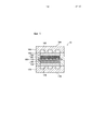
Фиг. 1 представляет собой графическое изображение, иллюстрирующее общую конфигурацию топливного элемента согласно одному варианту осуществления данного изобретения. Фиг. 1 схематично иллюстрирует строение поперечного сечения топливного элемента 10. Топливный элемент 10 включает в себя мембранно-электродный узел 100, газодиффузионные слои 140 и 150, катодную разделительную пластину 160, анодную разделительную пластину 170 и раму 180. Мембранно-электродный узел 100 включает в себя электролитную мембрану 110, слой 120 катодного катализатора и слой 130 анодного катализатора.FIG. 1 is a graphical illustration illustrating a general configuration of a fuel cell according to one embodiment of the present invention. FIG. 1 schematically illustrates the cross-sectional structure of a
[0027] Электролитная мембрана 110 может быть протон-проводящей ионообменной мембраной, сделанной, например, из фторполимера, такого как полимер перфторуглеродсульфоновой кислоты, или углеводородного полимера. В этом варианте осуществления Nafion (зарегистрированная торговая марка), произведенный duPont, использован для электролитной мембраны 110.[0027] The
[0028] Согласно этому варианту осуществления слой, включающий в себя углеродные нанотрубки (УНТ) с нанесенной платиной и иономер, использован в качестве слоя 120 катодного катализатора. С другой стороны, слой, включающий в себя углеродные частицы с нанесенной платиной и иономер, использован в качестве слоя 130 анодного катализатора. Слой 130 анодного катализатора не включает углеродные нанотрубки. В описании этого варианта осуществления электрод, состоящий из слоя катализатора, включающего в себя углеродные нанотрубки (УНТ) с нанесенной платиной и иономер, называется "УНТ-электрод", а электрод, состоящий из слоя катализатора, включающего в себя углеродные частицы с нанесенной платиной и иономер, называется "электрод с углеродными частицами". Слой 130 анодного катализатора представляет собой электрод с углеродными частицами в этом варианте осуществления, но альтернативно может быть УНТ-электродом. В этом варианте осуществления платина нанесена на углеродные частицы или углеродные, но вместо платины может быть использован сплав платины, такой как платина-кобальт, платина-рутений, платина-железо, платина-никель или платина-медь.[0028] According to this embodiment, a layer comprising platinum supported carbon nanotubes (CNTs) and an ionomer is used as the
[0029] Мембранно-электродный узел 100 имеет раму 180 на своей внешней периферии. Рама 180 сделана из полимера и сформирована так, чтобы быть объединенной с мембранно-электродным узлом 100 путем инжекционного формования полимера. Рама 180 поддерживает мембранно-электродный узел, а также служит в качестве прокладки, чтобы подавлять утечку топливного газа или окислительного газа.[0029] The
[0030] Углеродное полотно из углеродного нетканого материала или углеродной бумаги может быть использовано для газодиффузионных слоев 140 и 150. Этот вариант осуществления использует углеродное полотно из углеродной бумаги. Иное чем углеродное полотно или углеродная бумага, металлическое или полимерное пористое тело также может быть использовано для газодиффузионных слоев 140 и 150.[0030] A carbon web of carbon nonwoven fabric or carbon paper can be used for gas diffusion layers 140 and 150. This embodiment uses a carbon web of carbon paper. Other than a carbon sheet or carbon paper, a metallic or polymeric porous body can also be used for gas diffusion layers 140 and 150.
[0031] Катодная разделительная пластина 160 и анодная разделительная пластина 170 расположены так, чтобы вмещать мембранно-электродный узел 110 между ними. Катодная разделительная пластина 160 имеет пазы 165, сформированные на стороне мембранно-электродного узла 100. Пазы 165 используются для течения окислительного газа (воздуха). Аналогично, анодная разделительная пластина 170 имеет пазы 175, сформированные на стороне мембранно-электродного узла 100. Пазы 175 используются для течения топливного газа (водорода). Поверхность катодной разделительной пластины 160 на стороне, противоположной поверхности, где сформированы пазы 165, называется "поверхность 168". Поверхность анодной разделительной пластины 170 на стороне, противоположной поверхности, где сформированы пазы 175, называется "поверхность 178". При укладывании в стопку топливных элементов 10 поверхность 168 и поверхность 178 расположены так, что обращены друг к другу и вступают в контакт друг с другом. Чтобы сформировать траекторию течения охлаждающей среды между поверхностью 168 и поверхностью 178, по меньшей мере одна из поверхности 168 и поверхности 178 может иметь пазы для формирования траектории течения охлаждающей среды.[0031] The
[0032] В. Формирование каталитических электродов:[0032] B. Formation of catalytic electrodes:
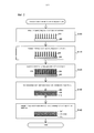
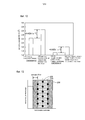
Фиг. 2 представляет собой графическое изображение, иллюстрирующее способ изготовления мембранно-электродного узла. Данный процесс получает рост углеродных нанотрубок 210 на кремниевой подложке 200 на этапе S100. Более конкретно, данный процесс сначала наносит железный катализатор в качестве центров роста углеродных нанотрубок 210, по существу, равномерно по кремниевой подложке 200 путем, например, напыления. Толщина железного катализатора предпочтительно составляет примерно от 50 до 200 нм. Толщина железного катализатора влияет на шаг между центрами углеродных нанотрубок 210 или численную плотность углеродных нанотрубок 210 (число углеродных нанотрубок 210 на единицу площади). Например, увеличение толщины железного катализатора уменьшает шаг между центрами углеродных нанотрубок 210 или увеличивает численную плотность углеродных нанотрубок 210. Предпочтительно экспериментально определять толщину железного катализатора согласно отношению к желаемому шагу между центрами или желаемой численной плотности углеродных нанотрубок 210. После напыления железного катализатора данный способ нагревает кремниевую подложку 200 до примерно 700°С для обработки отжигом. Обработка отжигом изменяет состояние железного катализатора на кремниевой подложке 200 от равномерно распределенного состояния до состояния точечных центров роста.FIG. 2 is a graphical illustration illustrating a manufacturing method of a membrane electrode assembly. This process receives the growth of
[0033] Данный способ затем получает рост углеродных нанотрубок 210 на кремниевой подложке 200, используя железный катализатор в качестве центров роста. Этот вариант осуществления применяет метод ХОГФ (химическое осаждение из газовой фазы) для получения роста углеродных нанотрубок 210. Данный способ сначала помещает обработанную отжигом кремниевую подложку 200 в кварцевую трубку и увеличивает температуру в кварцевой трубке до примерно 700°С в потоке газообразного гелия при пониженном давлении. Данный способ затем заменяет часть газообразного гелия газообразным ацетиленом и создает поток смешанного газа из газообразного гелия и газообразного ацетилена, вызывая рост углеродных нанотрубок 210. Обычно большее время протока смешанного газа из газообразного гелия и газообразного ацетилена дает более длинные углеродные нанотрубки 210. Более короткий шаг между центрами (более высокая численная плотность) дает более короткие углеродные нанотрубки 210 при фиксированном времени протока смешанного газа из газообразного гелия и газообразного ацетилена. Соответственно, предпочтительно экспериментально определять время протока смешанного газа из газообразного гелия и газообразного ацетилена, принимая во внимание длину углеродных нанотрубок 210 и шаг между центрами. Данный способ затем заменяет поток смешанного газа на поток только газообразного гелия, чтобы остановить рост углеродных нанотрубок и естественным образом охладить выращенные нанотрубки.[0033] This method then obtains the growth of
[0034] Когда углеродные нанотрубки 210 выращивают на кремниевой подложке с помощь способа ХОГФ, соседние углеродные нанотрубки 210 ограничивают рост углеродных нанотрубок 210 в направлении вдоль поверхности кремниевой подложки 200. Соответственно, углеродные нанотрубки 210 растут в направлении вдоль нормали к кремниевой подложке 200. Другими словами, углеродные нанотрубки 210 вероятно будут расти перпендикулярно кремниевой подложке 200.[0034] When
[0035] На этапе S110 данный процесс получает платину 220, нанесенную на углеродные нанотрубки 210. Например, данный процесс разбавляет раствор платината динитродиамина этанолом и добавляет разбавленный раствор платината по каплям на углеродные нанотрубки 210. Данный процесс затем высушивает, прокаливает и восстанавливает накапанный раствор платината, чтобы получить платину 220 нанесенной на углеродные нанотрубки 210. Предпочтительно подбирать концентрацию платины в растворе платината и регулировать число капель так, что количество нанесенной платины 220 составляет 0,1 [мг] на квадратный сантиметр электрода.[0035] In step S110, this process receives
[0036] На этапе S120 данный процесс покрывает поверхность углеродных нанотрубок 210 иономером 230. Более конкретно, данный процесс добавляет дисперсию иономера 230 по каплям на углеродные нанотрубки 210 и высушивает накапанный иономер 230 так, чтобы покрыть поверхность углеродных нанотрубок 210 иономером 230. Дисперсию иономера 230 готовят так, чтобы иметь отношение массы (I) иономера 230, включенного в дисперсию, к массе (С) углерода углеродных нанотрубок 210, в качестве объекта, подлежащего покрытию, т.е. массовое отношение (I/С) иономер/углерод, равное 1,5. Увеличение величины I/С увеличивает толщину покрытия иономером 230, тогда как снижение величины I/С уменьшает толщину покрытия иономером 230.[0036] In step S120, this process covers the surface of
[0037] На этапе S130 данный процесс соединяет углеродные нанотрубки 210 с электролитной мембраной 110, формируя слой 120 катодного катализатора. Более конкретно, данный процесс помещает электролитную мембрану 110 на концы углеродных нанотрубок 210 и соединяет углеродные нанотрубки 210 с электролитной мембраной 110 (термически переносит углеродные нанотрубки 210 в электролитную мембрану 110) под давлением 5 [МПа] при температуре 140 [°С]. Этот этап формирует слой 120 катодного катализатора.[0037] In step S130, this process connects the
[0038] На этапе S140 данный процесс наносит и высушивает каталитическую краску на другую поверхность электролитной мембраны 110, формируя слой 130 анодного катализатора. Более конкретно, данный процесс сначала добавляет этанол к углеродным частицам (например, углеродной саже), дополнительно добавляет водный раствор платинохлористоводородной кислоты и помешивает данную смесь. Данный процесс затем фильтрует углеродные частицы, содержащие раствор, чтобы получить платину, нанесенную на углеродные частицы, и углеродные частицы с нанесенной платиной. Данный способ затем добавляет этанол, воду и иономер к углеродным частицам с нанесенной платиной, помешивает данную смесь и выполняет ультразвуковое диспергирование, чтобы получить каталитическую краску. Данный процесс затем наносит и высушивает каталитическую краску на другую поверхность электролитной мембраны 110, формируя слой 130 анодного катализатора. На фиг. 2 мембранно-электродный узел 100 на этапе S140 переворачивают верхней стороной вниз относительно этапа S130. Эта последовательность этапов изготавливает мембранно-электродный узел 100.[0038] In step S140, this process applies and dries the catalytic paint to another surface of the
С. Оценка:C. Evaluation:
[0039] С-1. Измерение шага между центрами и длины углеродных нанотрубок:[0039] C-1. Measurement of the step between the centers and the length of carbon nanotubes:
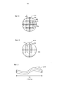
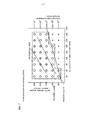
Фиг. 3 представляет собой графическое изображение, схематично иллюстрирующее кремниевую подложку 200, на которой выращены углеродные нанотрубки 210, наблюдаемое при помощи микроскопа сверху. Шаг Ра между центрами углеродных нанотрубок 210 может быть измерен с использованием микроскопа с микрометром, как показано на фиг. 3. Например, если подложка с выращенными на ней углеродными нанотрубками 210 наблюдается при помощи микроскопа сверху, то места, где выросли нанотрубки 210, изображаются в виде точек, как показано на фиг. 3. Соответственно, шаг Ра между центрами углеродных нанотрубок 210 может быть определен путем измерения интервала между двумя соседними углеродными нанотрубками 210 микрометром.FIG. 3 is a graphical diagram schematically illustrating a
[0040] Для удобства, углеродные нанотрубки 210 показаны на фиг. 3 расположенными по квадратной решетке. Углеродные нанотрубки 210, однако, в действительности размещаются случайным образом на кремниевой подложке 200. В таком фактическом состоянии шаг Ра между центрами углеродных нанотрубок 210 варьирует в зависимости от выбора углеродных нанотрубок 210 для измерения шага Ра между центрами. В этом случае шаг Ра между центрами может быть определен путем подсчета числа углеродных нанотрубок 210 на фиксированной площади Sa и, тем самым, путем вычисления числа углеродных нанотрубок 210 на единицу площади (численной плотности).[0040] For convenience,
[0041] Когда шаг между центрами углеродных нанотрубок 210 выражается как Ра [м], а число углеродных нанотрубок на квадратный метр (далее также называется "численной плотностью") выражается как Nd [штук/м2], то выполняется соотношение уравнения (1) или уравнения (2), приведенных ниже:[0041] When the step between the centers of the
Nd=1/(Ра)2 ... (1)Nd = 1 / (Pa) 2 ... (1)
Ра=(1/√(Nd)) ... (2)Ra = (1 / √ (Nd)) ... (2)
Соответственно, эта процедура посчитывает число углеродных нанотрубок 210 на площади Sa, чтобы вычислить численную плотность и затем определить шаг Ра между центрами углеродных нанотрубок 210 согласно уравнению (2).Accordingly, this procedure counts the number of
[0042] По фиг. 3 также может быть измерен внешний диаметр r углеродных нанотрубок 210. Внешний диаметр r углеродных нанотрубок 210, используемых в этом варианте осуществления, предпочтительно составляет от 5 до 50 [нм]. Когда внешний диаметр r углеродных нанотрубок 210 меньше чем 5 [нм], вероятно происходит пучкование или агрегация углеродных нанотрубок 210 в ходе добавления по каплям раствора платината динитродиамина или в ходе добавления по каплям иономера. Внутри пучка углеродных нанотрубок 210 поры для диффузии газа блокируются. Подавление пучкования, таким образом, желательно. С другой стороны, когда внешний диаметр r углеродных нанотрубок 210 больше чем 50 [нм], углеродные нанотрубки 210 имеют увеличенную жесткость. Это может вызывать проблему того, что углеродные нанотрубки 210 не сжимаются, а прокалываются сквозь электролитную мембрану 110 при приложении прижимающей нагрузки в ходе укладывания в стопку топливных элементов 10, создавая короткое замыкание. С точки зрения вышеприведенного обсуждения более предпочтительный внешний диаметр r углеродных нанотрубок 210 составляет от 10 до 30 [нм].[0042] Referring to FIG. 3, the outer diameter r of
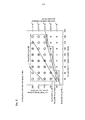
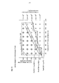
[0043] Фиг. 4 представляет собой графическое изображение, схематично иллюстрирующее кремниевую подложку 200, на которой выращены углеродные нанотрубки 210, наблюдаемое при помощи микроскопа сбоку. Длина La углеродных нанотрубок 210 может быть измерена с использованием микроскопа с микрометром, как показано на фиг. 4.[0043] FIG. 4 is a graphical diagram schematically illustrating a
[0044] Численная плотность Nd и шаг Ра между центрами углеродных нанотрубок 210 также могут быть вычислены с помощью следующей процедуры. Если внешний диаметр углеродных нанотрубок 210 выражается как r [м], масса углеродных нанотрубок 210 выражается как W [кг], степень кривизны углеродных нанотрубок 210 выражается как τ, толщина слоя углеродных нанотрубок выражается как Н [м] и плотность углеродных нанотрубок 210 выражается как d [кг/м3], то число углеродных нанотрубок 210 на кремниевой подложке 200 выражается в виде уравнения (3), приведенного ниже:[0044] The numerical density Nd and the pitch Pa between the centers of the
Число [штук]=(W/d)/(πr2×Н×τ) ... (3)The number of [pieces] = (W / d) / (πr 2 × N × τ) ... (3)
Толщина Н [м] слоя углеродных нанотрубок равна длине La углеродных нанотрубок 210.The thickness N [m] of the carbon nanotube layer is equal to the length La of the
[0045] В уравнении (3) (W/d) из числителя на правой стороне задается делением массы углеродных нанотрубок 210 на плотность углеродных нанотрубок и показывает объем, занимаемый углеродными нанотрубками 210 на кремниевой подложке 200, а πr2 знаменателя показывает площадь поперечного сечения одной углеродной нанотрубки 210. Соответственно, πr2×Н показывает объем одной углеродной нанотрубки 210 в предположении, что углеродная нанотрубка представляет собой прямой цилиндр. Углеродные нанотрубки 210, однако, не обязательно являются прямыми, но могут быть изогнутыми или искривленными, например, в форме волны. Степень изогнутости показана степенью кривизны τ. Степень кривизны τ может быть использована в качестве коэффициента преобразования для преобразования объема одной искривленной углеродной нанотрубки 210 из объема цилиндра. Уравнение (3) соответственно делит общий объем углеродных нанотрубок 210 на объем одной углеродной нанотрубки 210, чтобы вычислить число углеродных нанотрубок 210. Уравнение (3) определяет численную плотность углеродных нанотрубок 210 путем замены массы W [кг] углеродных нанотрубок 210 в уравнении (3) на массу w на квадратный метр [кг/м2]. Внешний диаметр r углеродных нанотрубок 210 и длина углеродных нанотрубок 210 могут быть измерены с использованием микроскопа с микрометром с помощью методов, показанных на фиг. 3 и 4. Плотность углеродных нанотрубок составляет от 1,33 до 1,40 [г/см3] (от 1,33×10³ до 1,40×10³ [кг/м3]).[0045] In equation (3), (W / d) from the numerator on the right side is given by dividing the mass of
[0046] Фиг. 5 представляет собой графическое изображение, схематично иллюстрирующее процедуру определения степени кривизны τ углеродных нанотрубок 210. Расстояние между соответствующими концами углеродной нанотрубки 210 выражается как La [м]. Это расстояние La может быть определено с помощью метода, показанного на фиг. 4. Длина углеродной нанотрубки 210 вдоль ее центральной оси выражается как Lb [м]. Длина Lb может быть определена, например, с использованием микрофотографии углеродных нанотрубок 210. Углеродные нанотрубки 210 изгибаются и искривляются в трех измерениях, так что предпочтительно определять длину Lb, используя два микроснимка, например, в двух разных направлениях, перпендикулярных друг другу. Степень кривизны τ вычисляют с помощью уравнения (4), приведенного ниже. Степень кривизны τ представляет собой безразмерное число и имеет значение не меньше чем 1:[0046] FIG. 5 is a graphical diagram schematically illustrating a procedure for determining the degree of curvature τ of
τ=Lb/La ... (4)τ = Lb / La ... (4)
[0047] С-2. Метод измерения характеристик генерации энергии:[0047] C-2. Method for measuring the characteristics of energy generation:
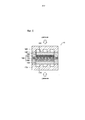
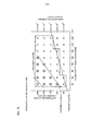
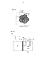
Фиг. 6 представляет собой графическое изображение, схематично иллюстрирующее топливный элемент для измерения характеристик генерации энергии. Топливный элемент, показанный на фиг. 6, отличается от топливного элемента, показанного на фиг. 1, следующим. В топливном элементе, показанном на фиг. 1, внешняя периферия электролитной мембраны 110 поддерживается рамой 180. С другой стороны, в топливном элементе, показанном на фиг. 6, обеспечены распорки 190 между катодной разделительной пластиной 160 и электролитной мембраной 110, и между анодной разделительной пластиной 170 и электролитной мембраной 110. Распорки 190 представляют собой элементы, используемые для определения толщины слоя 120 катодного катализатора и слоя 130 анодного катализатора в случае сдавливания и сжатия между катодной разделительной пластиной 160 и анодной разделительной пластиной 170. Толщина слоя 120 катодного катализатора и слоя 130 анодного катализатора после сжатия изменяются путем изменения толщины распорки 190.FIG. 6 is a graphical diagram schematically illustrating a fuel cell for measuring power generation characteristics. The fuel cell shown in FIG. 6 differs from the fuel cell shown in FIG. 1 as follows. In the fuel cell shown in FIG. 1, the outer periphery of the
[0048] С-3. Различные параметры углеродных нанотрубок и характеристик генерации энергии:[0048] C-3. Various parameters of carbon nanotubes and energy generation characteristics:
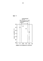
Фиг. 7 представляет собой график, показывающий результаты оценки характеристик генерации энергии, когда толщина слоя углеродного катализатора сжата до 20 [мкм]. На фиг. 7 абсцисса показывает толщину La слоя углеродных нанотрубок до сжатия; левая ордината показывает шаг между центрами углеродных нанотрубок; а правая ордината показывает численную плотность углеродных нанотрубок. Толщина La слоя углеродных нанотрубок перед сжатием соответствует длине La углеродных нанотрубок 210, измеренной на фиг. 4, как описано выше. Ниже показаны условия электрода, условия измерения и оценочные критерии, используемые для оценки характеристик генерации энергии:FIG. 7 is a graph showing the results of evaluating energy generation characteristics when the thickness of the carbon catalyst layer is compressed to 20 [μm]. In FIG. 7, the abscissa shows the thickness of the La layer of carbon nanotubes before compression; the left ordinate shows the step between the centers of carbon nanotubes; and the right ordinate shows the numerical density of carbon nanotubes. The thickness La of the carbon nanotube layer before compression corresponds to the length La of
(1) Условия электрода:(1) Electrode conditions:
количество нанесенной платины: 0,1 [мг/см2]amount of platinum deposited: 0.1 [mg / cm 2 ]
иономер: DЕ2020СS, изготовленный duPontionomer: DE2020СS manufactured by duPont
массовое отношение I/С=1,5mass ratio I / C = 1.5
(2) Условия измерения:(2) Measurement conditions:
температура элемента: 70°Сelement temperature: 70 ° C
анодный газ: стехиометрическое отношение 1,2, давление 140 [кПа], без увлажненияanode gas: stoichiometric ratio of 1.2, pressure 140 [kPa], without humidification
катодный газ: стехиометрическое отношение 1,5, давление 140 [кПа], без увлажненияcathode gas: stoichiometric ratio of 1.5, pressure 140 [kPa], without humidification
(3) Оценочные критерии:(3) Evaluation criteria:
Измеряли напряжение при отведении электрического тока 2,0 [А/см2] из топливного элемента. Напряжение не ниже чем 0,6 [В] оценивали как отличное, и это показано двойным кружком на фиг. 7. Напряжение выше, чем 0 [В], но ниже, чем 0,6 [В], оценивали как хорошее, и это показано кружком на фиг. 7. Отказ генерации энергии оценивали как отсутствующую генерацию энергии, и это показано крестиком на фиг. 7.Measured voltage during the removal of electric current 2.0 [A / cm 2 ] from the fuel cell. A voltage of not lower than 0.6 [V] was rated as excellent, and this is shown by a double circle in FIG. 7. A voltage higher than 0 [V] but lower than 0.6 [V] was rated as good, and this is indicated by a circle in FIG. 7. Failure of energy generation was evaluated as missing energy generation, and this is indicated by a cross in FIG. 7.
[0049] Как показано на фиг. 7, следующие диапазоны являются диапазонами, имеющими хорошие или отличные характеристики генерации энергии.[0049] As shown in FIG. 7, the following ranges are ranges having good or excellent power generation characteristics.
Pa [нм]Step between centers
Pa [nm]
La [мкм]CNT length before compression
La [μm]
Nd [штук/м2]Numerical density
Nd [pcs / m 2 ]
[0050] Диапазоны, имеющие хорошие или отличные характеристики генерации энергии на фиг. 7, могут быть выражены как диапазоны, одновременно удовлетворяющие выражениям (5) и (6), приведенным ниже:[0050] Ranges having good or excellent power generation characteristics in FIG. 7 can be expressed as ranges that simultaneously satisfy expressions (5) and (6) below:
30≤La≤240 ... (5)30≤La≤240 ... (5)
0,351×La+75≤Ра≤250 ... (6)0.351 × La + 75≤Pa≤250 ... (6)
Например, когда длина La углеродных нанотрубок 210 перед сжатием составляет La=30 [мкм], согласно выражению (6) диапазон шага Ра [нм] между центрами задается выражением (7), приведенным ниже:For example, when the length La of
0,351×30+75=85,53 [нм]≤Ра≤250 [нм] ... (7)0.351 × 30 + 75 = 85.53 [nm] ≤Pa≤250 [nm] ... (7)
Максимальная величина длины La (240 [мкм]) и максимальная величина шага Ра (250 [нм]) между центрами являются максимальными значениями этих параметров, использованными для оценки, и диапазоны, не превышающие эти максимальные значения, являются достаточными при практическом использовании.The maximum length La (240 [μm]) and the maximum step Ra (250 [nm]) between the centers are the maximum values of these parameters used for evaluation, and ranges not exceeding these maximum values are sufficient for practical use.
[0051] Диапазоны, имеющие хорошие или отличные характеристики генерации энергии на фиг. 7, также могут быть выражены с помощью выражений (8) и (9), приведенных ниже, вместо вышеприведенных выражений (5) и (6) с использованием длины La [мкм] и численной плотности Nd [штук/м2] углеродных нанотрубок 210 перед сжатием:[0051] Ranges having good or excellent power generation characteristics in FIG. 7 can also be expressed using expressions (8) and (9) below, instead of the above expressions (5) and (6) using the length La [μm] and the numerical density Nd [pcs / m 2 ] of
30≤La≤240 ... (8)30≤La≤240 ... (8)
1,7×10¹³≤Nd≤1×10¹⁸/(0,351×La+75)2 ... (9)1.7 × 10 13 ≤Nd≤1 × 10 18 / (0.351 × La + 75) 2 ... (9)
В выражении (9) (0,351×La+75) в знаменателе дается в единицах нанометров [нм], как показано выражением (7). Соответственно, выражение (9) умножает числитель на правой стороне на (1×10¹⁸) для преобразования в "на квадратный метр".In expression (9) (0.351 × La + 75) in the denominator is given in units of nanometers [nm], as shown by expression (7). Accordingly, expression (9) multiplies the numerator on the right side by (1 × 10 18 ) to convert to "per square meter".
[0052] Диапазоны, имеющие отличные характеристики генерации энергии на фиг. 7, могут быть выражены как диапазоны, одновременно удовлетворяющие выражениям (10) и (11), приведенным ниже:[0052] Ranges having excellent power generation characteristics in FIG. 7 can be expressed as ranges that simultaneously satisfy expressions (10) and (11) below:
60≤La≤210 ... (10)60≤La≤210 ... (10)
0,666×La+80≤Ра≤0,833×La+132,5... (11)0.666 × La + 80≤Pa≤0.833 × La + 132.5 ... (11)
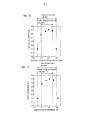
[0053] Фиг. 8-10 представляют собой графики, показывающие результаты оценки характеристик генерации энергии, когда толщина слоя 120 углеродного катализатора сжата до 15 [мкм], 10 [мкм] и 5 [мкм] соответственно. Фиг. 8-10 имеют другие толщины слоя 120 катодного катализатора после сжатия относительно толщины на фиг. 7, но в других отношениях применяют такие же условия. Последующее описывает отличные и хорошие диапазоны и отличные диапазоны для соответствующих графиков.[0053] FIG. 8-10 are graphs showing the results of evaluating energy generation characteristics when the thickness of the
[0054] Диапазоны, имеющие хорошие и отличные характеристики генерации энергии на фиг. 8, могут быть выражены как диапазоны, одновременно удовлетворяющие выражениям (12) и (13), приведенным ниже:[0054] Ranges having good and excellent power generation characteristics in FIG. 8 can be expressed as ranges that simultaneously satisfy expressions (12) and (13) below:
30≤La≤240 ... (12)30≤La≤240 ... (12)
0,381×La+78,6≤Ра≤250 ... (13)0.381 × La + 78.6≤Pa≤250 ... (13)
Диапазоны, имеющие отличные характеристики генерации энергии на фиг. 8, могут быть выражены как диапазоны, одновременно удовлетворяющие выражениям (14) и (15), приведенным ниже:Ranges having excellent power generation characteristics in FIG. 8 can be expressed as ranges that simultaneously satisfy expressions (14) and (15) below:
30≤La≤210 ... (14)30≤La≤210 ... (14)
0,78×La+78≤Ра≤1,333×La+150 ... (15)0.78 × La + 78≤Pa≤1,333 × La + 150 ... (15)
[0055] Диапазоны, имеющие хорошие и отличные характеристики генерации энергии на фиг. 9, могут быть выражены как диапазоны, одновременно удовлетворяющие выражениям (16) и (17), приведенным ниже:[0055] Ranges having good and excellent power generation characteristics in FIG. 9 can be expressed as ranges that simultaneously satisfy expressions (16) and (17) below:
30≤La≤240 ... (16)30≤La≤240 ... (16)
0,705×La+59,3≤Ра≤250 ... (17)0.705 × La + 59.3≤Ra≤250 ... (17)
Диапазоны, имеющие отличные характеристики генерации энергии на фиг. 9, могут быть выражены как диапазоны, одновременно удовлетворяющие выражениям (18) и (19), приведенным ниже:Ranges having excellent power generation characteristics in FIG. 9 can be expressed as ranges that simultaneously satisfy expressions (18) and (19) below:
30≤La≤240 ... (18)30≤La≤240 ... (18)
0,611×La+82,5≤Ра≤1,333×La+190 ... (19)0.611 × La + 82.5≤Pa≤1.333 × La + 190 ... (19)
Определение выражения (19) с помощью численной плотности Nd дает выражение (20) ниже.The definition of expression (19) using the numerical density Nd gives expression (20) below.
1×10¹⁸/(1,333×La+190)2≤Nd≤1×1018/(0,611×La+82,5)2 ... (20)1 × 10 18 / (1.333 × La + 190) 2 ≤Nd≤1 × 10 18 / (0.611 × La + 82.5) 2 ... (20)
[0056] Диапазоны, имеющие хорошие и отличные характеристики генерации энергии на фиг. 10, могут также быть выражены с помощью выражений (21) и (22), приведенных ниже:[0056] Ranges having good and excellent power generation characteristics in FIG. 10 can also be expressed using expressions (21) and (22) below:
30≤La≤150 ... (21)30≤La≤150 ... (21)
0,966×La+95,5≤Ра≤250 ... (22)0.966 × La + 95.5≤Pa≤250 ... (22)
Диапазоны, имеющие отличные характеристики генерации энергии на фиг. 10, могут быть выражены как диапазоны, одновременно удовлетворяющие выражениям (23) и (24), приведенным ниже:Ranges having excellent power generation characteristics in FIG. 10 can be expressed as ranges that simultaneously satisfy expressions (23) and (24) below:
30≤La≤150 ... (23)30≤La≤150 ... (23)
0,966×La+95,5≤Ра≤1,333×La+190 ... (24)0.966 × La + 95.5≤Pa≤1.333 × La + 190 ... (24)
[0057] Согласно сравнению фиг. 7-10, уменьшение толщины слоя 120 катодного катализатора расширяет диапазон отсутствия генерации энергии в нижней правой части графика. Этот диапазон имеет короткий шаг Ра между центрами (или более высокую численную плотность Nd) углеродных нанотрубок 210 и большую длину La углеродных нанотрубок 210 перед сжатием. Когда слой 120 катодного катализатора сжат в этом диапазоне, ожидается, что сжатие будет блокировать поры между углеродными нанотрубками 210 и ухудшать коэффициент диффузии газа или дренаж получаемой воды. Другими словами, ожидается, что большее сжатие углеродных нанотрубок 210 будет давать больший диапазон отсутствия генерации энергии в нижней правой части графика. Ухудшение коэффициента диффузии газа и дренажа может увеличивать концентрационное перенапряжение и вызывать падение напряжения даже в случае возможности генерации энергии.[0057] According to the comparison of FIG. 7-10, a decrease in the thickness of the
[0058] Когда слой 120 катодного катализатора сжат до 5 [мкм] или тоньше, прикладывают высокую прижимающую нагрузку в ходе укладывания в стопку топливных элементов 10. В этом случае, из-за высокой прижимающей нагрузки, углеродные нанотрубки 210 в слое 120 катодного катализатора и углеродные волокна в газодиффузионном слое 140 вероятно будут прокалываться сквозь электролитную мембрану 110 и вызывать поперечную утечку. Соответственно, предпочтительно не сжимать слой 120 катодного катализатора до толщины 5 [мкм] или тоньше.[0058] When the
[0059] Согласно сравнению диапазонов с отличными характеристики генерации энергии, площадь этого отличного диапазона является максимальной в случае сжатия слоя катодного катализатора до 10-15 [мкм] (фиг. 8, фиг. 9) и снижается как в случае меньшего сжатия, так и в случае большего сжатия. Сжатие укорачивает расстояние между электролитной мембраной 110 и слоем 120 катодного катализатора, где происходит генерация энергии. Это поддерживает протонную проводимость от электролитной мембраны 110 через иономер 230 к катализатору для топливного элемента (платина 220) в хорошем состоянии и, тем самым, улучшает характеристики генерации энергии. Избыточное сжатие может, однако, вызывать то, чтобы было заблокировано большее число пор между углеродными нанотрубками 210, и приводит к дополнительному ухудшению коэффициента диффузии газа или дренажа получаемой воды, как описано выше. Путем уравновешивания этих факторов площадь диапазона, имеющего отличные характеристики генерации энергии, максимизируется, когда слой 120 катодного катализатора сжат до 10-15 [мкм].[0059] According to the comparison of ranges with excellent energy generation characteristics, the area of this excellent range is maximum when the cathode catalyst layer is compressed to 10-15 [μm] (Fig. 8, Fig. 9) and decreases both in the case of less compression and in case of greater compression. Compression shortens the distance between the
[0060] Фиг. 11 представляет собой график, показывающий зависимость между толщиной катализатора и плотностью тока после сжатия слоя катодного катализатора. На фиг. 11 плотность тока при напряжении 0,6 В отложена по отношению к толщине слоя 120 катодного катализатора в условиях, когда длина La углеродных нанотрубок 210 перед сжатием составляет 40 [мкм], а шаг Ра между центрами углеродных нанотрубок 210 составляет 170 [нм]. Согласно фиг. 11, диапазон толщины слоя 120 катодного катализатора после сжатия предпочтительно составляет диапазон от 5 [мкм] до 20 [мкм] и более предпочтительно диапазон от 7,5 [мкм] до 17,5 [мкм]. Нижний предел более предпочтительного диапазона устанавливают не на 5 [мкм], а на 7,5 [мкм] соответственно результатам фиг. 7-10.[0060] FIG. 11 is a graph showing the relationship between the thickness of the catalyst and the current density after compression of the cathode catalyst layer. In FIG. 11, the current density at a voltage of 0.6 V is plotted relative to the thickness of the
[0061] С-4. Характеристики генерации энергии относительно иономера:[0061] C-4. Characteristics of energy generation relative to ionomer:
Фиг. 12 представляет собой график, показывающий сравнение между плотностями тока при использовании стандартного иономера и иономера с высоким содержанием растворенного кислорода. В этом сравнении DЕ2020СS, произведенный duPont, использовали в качестве стандартного иономера, а иономер, показанный следующей химической формулой (хим.1), раскрытый в принадлежащей тому же правообладателю японской патентной заявке 2010-229903 (JP 2012-84398А), использовали в качестве иономера с высоким содержанием растворенного кислорода.FIG. 12 is a graph showing a comparison between current densities using a standard ionomer and a high dissolved oxygen ionomer. In this comparison, DE2020СS manufactured by duPont was used as the standard ionomer, and the ionomer shown by the following chemical formula (Chem. 1), disclosed in the same copyright holder of Japanese patent application 2010-229903 (JP 2012-84398A), was used as the ionomer high in dissolved oxygen.

[0062] В вышеприведенной химической формуле (хим.1) R1 и R2 соответственно обозначают атом фтора или перфторалкильную группу, содержащую от 1 до 10 атомов углерода. Перфторалкильная группа R1 или R2 может содержать атом кислорода в молекулярной цепи. R3 обозначает перфторалкиленовую группу, содержащую от 1 до 10 атомов углерода. Перфторалкиленовая группа R3 может содержать атом кислорода в молекулярной цепи. Сульфогруппа (-SO3Н) может быть замещена трифторметильной группой (-CF3). В данной формуле m представляет собой целое число не меньше чем 1.[0062] In the above chemical formula (Chem. 1), R1 and R2 respectively represent a fluorine atom or a perfluoroalkyl group containing from 1 to 10 carbon atoms. The perfluoroalkyl group R1 or R2 may contain an oxygen atom in the molecular chain. R3 represents a perfluoroalkylene group containing from 1 to 10 carbon atoms. The perfluoroalkylene group R3 may contain an oxygen atom in the molecular chain. The sulfo group (—SO 3 H) may be substituted with a trifluoromethyl group (—CF 3 ). In this formula, m is an integer of not less than 1.
[0063] Иономер с высоким содержанием растворенного кислорода может быть получен путем полимеризации мономера, выраженного следующей химической формулой (хим.2):[0063] The ionomer with a high content of dissolved oxygen can be obtained by polymerization of a monomer expressed by the following chemical formula (chemical 2):

[0064] Согласно сравнению между электродом с углеродными частицами и УНТ-электродом на фиг. 12, УНТ-электрод имеет более высокую плотность тока. Кроме того, в отношении и электрода с углеродными частицами, и УНТ-электрода, использование иономера с высоким содержанием растворенного кислорода дает более высокую плотность тока, чем использование стандартного иономера. Особенно когда иономер заменяют от стандартного иономера на иономер с высоким содержанием растворенного кислорода, использование УНТ-электрода дает большую величину увеличения плотности тока, чем использование электрода с углеродными частицами.[0064] According to the comparison between the carbon particle electrode and the CNT electrode in FIG. 12, the CNT electrode has a higher current density. In addition, with respect to both the carbon particle electrode and the CNT electrode, the use of an ionomer with a high dissolved oxygen content gives a higher current density than using a standard ionomer. Especially when the ionomer is replaced from a standard ionomer by an ionomer with a high content of dissolved oxygen, the use of a CNT electrode gives a larger magnitude of the increase in current density than the use of an electrode with carbon particles.
[0065] Фиг. 13 представляет собой график, показывающий зависимость структуры электрода от концентрации кислорода в иономере, когда углеродные нанотрубки используют для материала электрода. Когда углеродную нанотрубку 210 используют для материала электрода, углеродная нанотрубка 210 имеет большое число π электронов, так что электроны легко передвигаются по углеродной нанотрубке 210. Вся поверхность углеродной нанотрубки 210 приблизительно цилиндрической формы имеет тонкое покрытие из иономера 230. Расстояние от поверхности иономера 230 до платины 220 является таким коротким, как приблизительно 10 нм. Вследствие короткого расстояния от поверхности иономера 230 до платины коэффициент диффузии кислорода в иономер 230 не влияет значительно на характеристики генерации энергии. В этом случае увеличение растворимости кислорода в иономере 230 делает возможным, чтобы высокая концентрация кислорода была подведена к платине 220. Соответственно, использование иономера с высоким содержанием растворенного кислорода увеличивает величину притока кислорода к платине и, тем самым, увеличивает плотность тока.[0065] FIG. 13 is a graph showing the dependence of the electrode structure on the oxygen concentration in the ionomer when carbon nanotubes are used for the electrode material. When a
[0066] Фиг. 14 представляет собой график, показывающий зависимость структуры электрода от концентрации кислорода в иономере, когда углеродные частицы используют для материала электрода. Когда углеродные частицы 250 используют для материала электрода, углеродные частицы 250 образуют агрегат, который покрыт иономером 230. Даже когда сами углеродные частицы 250 имеют электрическую проводимость, большое контактное сопротивление между углеродными частицами 250, образующими агрегат, затрудняет протекание электрического тока. Кроме того, присутствие части платины 220 (катализатор), не покрытой иономером, предотвращает протоны от доставки ко всей платине. Соответственно, УНТ-электрод дает более высокую плотность тока, чем электрод с углеродными частицами. Углеродные частицы 250 электрода с углеродными частицами образуют большой ком агрегата. В этом случае среднее расстояние от поверхности иономера 230 до платины является относительно большим, например, примерно 100 нм. Вследствие большого расстояния перемещения кислорода в иономере 230 не только растворимость кислорода в иономере 230, но и коэффициент диффузии кислорода в иономере 230 влияют на характеристики генерации энергии. Использование иономера с высоким содержанием растворенного кислорода в качестве иономера 230 увеличивает плотность тока, но не увеличивает плотность так эффективно, как использование УНТ-электрода. УНТ-электрод, имеющий более тонкое покрытие иономером 230 и более короткое расстояние от поверхности иономера 230 до платины, обладает меньшим влиянием на коэффициент диффузии кислорода в иономере 230 и, таким образом, вероятно повышает плотность тока.[0066] FIG. 14 is a graph showing the dependence of the electrode structure on the oxygen concentration in the ionomer when carbon particles are used for the electrode material. When
[0067] Фиг. 15 представляет собой графическое изображение, иллюстрирующее один пример устройства для измерения растворимости кислорода в иономере. Способ, описанный в цитированном документе "Z. Ogumi, Z. Takehara and S. Yoshizawa, J. Electrochem. Soc., 131, 769 (1984)", применяли для измерения растворимости кислорода в иономере. Устройство 300 для измерения растворимости кислорода в иономере включает в себя мембрану 310 в качестве объекта, подлежащего измерению, рабочий электрод 320, противоэлектрод 330, электрод 340 сравнения, газовую камеру 350 и камеру для раствора 360. Мембрану 310 помещают так, чтобы отделять газовую камеру 350 от камеры для раствора 360. Камеру для раствора 360 наполняют, например, 0,5М раствором сульфата калия. Рабочий электрод 320 размещается на поверхности мембраны 310 со стороны камеры для раствора 360. Рабочий электрод 320 сформирован из SPE композитного электрода. Противоэлектрод 330 и электрод 340 сравнения находятся в камере для раствора 360. Электрод серебро/хлорид серебра используется в качестве электрода 340 сравнения. Стандартный водородный электрод (СВЭ) или насыщенный каломельный электрод могут быть использованы вместо электрода серебро/хлорид серебра. Однако обычно применяется электрод серебро/хлорид серебра, так как стандартный водородный электрод имеет затруднение в подстройке парциального давления водорода, а насыщенный каломельный электрод использует ртуть.[0067] FIG. 15 is a graphical illustration illustrating one example of a device for measuring the solubility of oxygen in an ionomer. The method described in the cited document "Z. Ogumi, Z. Takehara and S. Yoshizawa, J. Electrochem. Soc., 131, 769 (1984)" was used to measure the solubility of oxygen in the ionomer. A
[0068] Газовую камеру 350 заранее наполняют азотом, и затем кислород вводят в газовую камеру. Кислород растворяется в мембране 310 и движется к рабочему электроду 320. Растворимость кислорода в мембране 310 вычисляют путем измерения потенциала с использованием рабочего электрода 320. Например, растворимость кислорода в мембране 310 может быть вычислена путем вычисления концентрации кислорода в мембране 310 из измеренного потенциала согласно уравнению Нернста.[0068] The
[0069] Согласно описанию таблицы III в "Zempachi Ogumi, Tohru Kuroe and Zen-ichiro Takehara, J. Electrochem. Soc.: ELECTROCHEMICAL SCIENCE AND TECHNOLOGY November 1985, Vol. 132, No.11", растворимость кислорода в Nafion составляет от 10,7 до 10,9 [моль/дм3]. Соответственно, предпочтительно использовать иономер, имеющий растворимость кислорода больше чем эта величина, например, иономер, имеющий растворимость кислорода не меньше чем 20 моль/дм3, что почти в два раза превышает растворимость кислорода в Nafion.[0069] According to the description of table III in "Zempachi Ogumi, Tohru Kuroe and Zen-ichiro Takehara, J. Electrochem. Soc .: ELECTROCHEMICAL SCIENCE AND TECHNOLOGY November 1985, Vol. 132, No.11", the solubility of oxygen in Nafion is from 10 7 to 10.9 [mol / dm 3 ]. Accordingly, it is preferable to use an ionomer having an oxygen solubility greater than this value, for example, an ionomer having an oxygen solubility of not less than 20 mol / dm 3 , which is almost two times the oxygen solubility in Nafion.
[0070] Фиг. 16 представляет собой график, показывающий зависимость массового отношения иономер/углерод от плотности тока. На фиг. 16 плотность тока при напряжении 0,6 В отложена относительно массового отношения (I/С) иономер/углерод слоя 120 катодного катализатора в условиях, когда длина La углеродных нанотрубок 210 перед сжатием составляет 40 [мкм], а шаг Ра между центрами углеродных нанотрубок 210 составляет 170 [нм]. Массовое отношение иономер/углерод в диапазоне не ниже чем 0,5 и не выше чем 3,0 дает плотность тока не ниже чем 2,0 [А/см2] при напряжении 0,6 [В]. Массовое отношение иономер/углерод в диапазоне не ниже чем 1,0 и не выше чем 2,5 дает плотность тока не ниже чем 2,5 [А/см2] при напряжении 0,6 [В]. Соответственно, массовое отношение иономер/углерод предпочтительно составляет не ниже чем 0,5 и не выше чем 3,0 и более предпочтительно не ниже чем 1,0 и не выше чем 2,5.[0070] FIG. 16 is a graph showing the dependence of the ionomer / carbon mass ratio on current density. In FIG. 16, the current density at a voltage of 0.6 V is plotted relative to the mass ratio (I / C) of the ionomer / carbon of the
[0071] Фиг. 17 представляет собой график, показывающий зависимость толщины покрытия иономером углеродных нанотрубок от плотности тока. На фиг. 17 плотность тока при напряжении 0,6 В отложена относительно толщины покрытия иономером слоя 120 катодного катализатора в условиях, когда длина La углеродных нанотрубок 210 перед сжатием составляет 40 [мкм], а шаг Ра между центрами углеродных нанотрубок 210 составляет 170 [нм]. Толщина покрытия иономером не меньше чем 2,5 [нм] и не больше чем 15 [нм] дает плотность тока не ниже чем 2,0 [А/см2] при напряжении 0,6 [В]. Толщина покрытия иономером не меньше чем 5 [нм] и не больше чем 12,5 [нм] дает плотность тока не ниже чем 2,5 [А/см2] при напряжении 0,6 [В]. Соответственно, толщина покрытия иономером предпочтительно составляет не меньше чем 2,5 [нм] и не больше чем 15 [нм] и более предпочтительно не меньше чем 5 [нм] и не больше чем 12,5 [нм].[0071] FIG. 17 is a graph showing the dependence of the thickness of a coating of a carbon nanotube ionomer on a current density. In FIG. 17, the current density at a voltage of 0.6 V is plotted relative to the ionomer coating thickness of the
[0072] Последующее описывает некоторые аспекты данного изобретения со ссылкой на некоторые варианты осуществления. Варианты осуществления, описанные выше, представлены только в целях облегчить понимание данного изобретения, а не с целью ограничения изобретения каким-либо образом. Данное изобретение может быть изменено или модифицировано без отклонения от объема изобретения и включает в себя свои эквиваленты.[0072] The following describes some aspects of the present invention with reference to some embodiments. The embodiments described above are presented only to facilitate understanding of the present invention, and not to limit the invention in any way. The invention may be changed or modified without departing from the scope of the invention and includes its equivalents.
[0073] Список численных обозначений[0073] List of numerals
10 ... топливный элемент10 ... fuel cell
20 ... углеродная нанотрубка20 ... carbon nanotube
100 ... мембранно-электродный узел100 ... membrane electrode assembly
120 ... слой катодного катализатора120 ... cathode catalyst layer
130 ... слой анодного катализатора130 ... anode catalyst bed
140 ... газодиффузионный слой140 ... gas diffusion layer
160 ... катодная разделительная пластина160 ... cathode separation plate
165 ... паз165 ... groove
168 ... поверхность168 ... surface
170 ... анодная разделительная пластина170 ... anode spacer plate
175 ... паз175 ... groove
178 ... поверхность178 ... surface
180 ... рама180 ... frame
190 ... распорка190 ... spacer
200 ... кремниевая подложка200 ... silicon substrate
210 ... углеродная нанотрубка210 ... carbon nanotube
220 ... платина220 ... platinum
230 ... иономер230 ... ionomer
250 ... углеродная частица250 ... carbon particle
300 ... устройство для измерения300 ... measuring device
310 ... мембрана310 ... membrane
320 ... рабочий электрод320 ... working electrode
330 ... противоэлектрод330 ... counter electrode
340 ... сравнительный электрод340 ... reference electrode
350 ... газовая камера350 ... gas chamber
360 ... камера для раствора360 ... solution chamber
r ... диаметрr ... diameter
W ... массаW ... mass
w ... массаw ... mass
SA ... площадьSA ... area
Ра ... шаг между центрамиRa ... step between the centers
Sa ... площадьSa ... area
La ... длинаLa ... length
Nd ... численная плотностьNd ... numerical density
Claims (13)
углеродные нанотрубки;
катализатор для топливного элемента, нанесенный на углеродные нанотрубки; и
иономер, обеспеченный так, чтобы покрывать углеродные нанотрубки и катализатор для топливного элемента, причем
если длина углеродных нанотрубок обозначена как La [мкм], а шаг между центрами углеродных нанотрубок обозначен как Ра [нм], то длина La и шаг Ра между центрами удовлетворяют двум выражениям, приведенным ниже:
30≤La≤240; и
0,351×La+75≤Ра≤250; и при этом электрод для топливного элемента, содержащий нанотрубки, соединен с электролитной мембраной путем термического давления и затем сжат до толщины не менее 7,5 [мкм] и не более чем 17,5 [мкм], чтобы быть использованным в качестве катализатора для топливного элемента.1. An electrode for a fuel cell, comprising:
carbon nanotubes;
a catalyst for a fuel cell deposited on carbon nanotubes; and
an ionomer provided to coat carbon nanotubes and a catalyst for a fuel cell, wherein
if the length of carbon nanotubes is denoted by La [μm], and the step between the centers of carbon nanotubes is denoted by Ra [nm], then the length of La and the step Pa between the centers satisfy the two expressions below:
30≤La≤240; and
0.351 × La + 75≤Pa≤250; and while the electrode for the fuel cell containing nanotubes is connected to the electrolyte membrane by thermal pressure and then compressed to a thickness of not less than 7.5 [μm] and not more than 17.5 [μm] to be used as a catalyst for fuel item.
углеродные нанотрубки;
катализатор для топливного элемента, нанесенный на углеродные нанотрубки; и
иономер, обеспеченный так, чтобы покрывать углеродные нанотрубки и катализатор для топливного элемента, причем
если длина углеродных нанотрубок обозначена как La [мкм], а шаг между центрами углеродных нанотрубок обозначен как Ра [нм], то длина La и шаг Ра между центрами удовлетворяют двум выражениям, приведенным ниже:
30≤La≤240; и
0,351×La+75≤Ра≤250;
и при этом (масса иономера)/(масса углеродных нанотрубок), что является отношением массы иономера к массе углеродных нанотрубок, составляет не меньше чем 1,0 и не больше чем 2,5.2. An electrode for a fuel cell, comprising:
carbon nanotubes;
a catalyst for a fuel cell deposited on carbon nanotubes; and
an ionomer provided to coat carbon nanotubes and a catalyst for a fuel cell, wherein
if the length of carbon nanotubes is denoted by La [μm], and the step between the centers of carbon nanotubes is denoted by Ra [nm], then the length of La and the step Pa between the centers satisfy the two expressions below:
30≤La≤240; and
0.351 × La + 75≤Pa≤250;
and (mass of ionomer) / (mass of carbon nanotubes), which is the ratio of the mass of ionomer to the mass of carbon nanotubes, is not less than 1.0 and not more than 2.5.
длина La и шаг Ра между центрами удовлетворяют выражению, приведенному ниже:
0,708×La+59,3≤Ра≤250.3. The electrode for a fuel cell according to claim 1 or 2, wherein
the length La and the pitch Pa between the centers satisfy the expression below:
0.708 × La + 59.3≤Pa≤250.
длина La и шаг Ра между центрами удовлетворяют выражению, приведенному ниже:
30≤La≤120; и
0,611×La+82,5≤Ра≤1,333×La+190.4. The electrode for a fuel cell according to claim 3, wherein
the length La and the pitch Pa between the centers satisfy the expression below:
30≤La≤120; and
0.611 × La + 82.5≤Pa≤1.333 × La + 190.
длина La и шаг Ра между центрами удовлетворяют выражению, приведенному ниже:
0,78×La+78≤Ра≤1,333×La+150.5. The electrode for a fuel cell according to claim 4, wherein
the length La and the pitch Pa between the centers satisfy the expression below:
0.78 × La + 78≤Pa≤1,333 × La + 150.
иономер покрывает углеродные нанотрубки толщиной не менее чем 2,5 [нм] и не более чем 15 [нм].6. The electrode for a fuel cell according to claim 1 or 2, wherein
the ionomer covers carbon nanotubes with a thickness of not less than 2.5 [nm] and not more than 15 [nm].
иономер покрывает углеродные нанотрубки толщиной не менее чем 5 [нм] и не более чем 12,5 [нм].7. An electrode for a fuel cell according to claim 6, wherein
the ionomer covers carbon nanotubes with a thickness of not less than 5 [nm] and not more than 12.5 [nm].
причем иономер имеет растворимость кислорода, которая выше чем 10,9 моль/дм3.8. The electrode for the fuel cell according to claim 1 or 2,
moreover, the ionomer has a solubility of oxygen, which is higher than 10.9 mol / DM 3 .
причем иономер имеет растворимость кислорода, которая равна или выше чем 20 моль/дм3.9. The electrode for the fuel cell according to claim 8,
moreover, the ionomer has a solubility of oxygen, which is equal to or higher than 20 mol / DM 3 .
выращивание углеродных нанотрубок на подложке, так что, если длина углеродных нанотрубок обозначена как La [мкм], а шаг между центрами углеродных нанотрубок обозначен как Ра [нм], то длина La и шаг Ра между центрами удовлетворяют двум выражениям, приведенным ниже:
30≤La≤240; и
0,351×La+75≤Ра≤250;
получение катализатора для топливного элемента, нанесенного на углеродные нанотрубки;
покрытие углеродных нанотрубок иономером;
соединение углеродных нанотрубок с электролитной мембраной путем приложения термического давления для формирования первого слоя катализатора; и
соединение с электролитной мембраной посредством термического давления и затем сжатия до толщины не менее 7,5 [мкм] и не более чем 17,5 [мкм].10. A method of manufacturing an electrode for a fuel cell, comprising:
growing carbon nanotubes on a substrate, so if the length of the carbon nanotubes is denoted by La [μm], and the step between the centers of the carbon nanotubes is denoted by Ra [nm], then the length of La and the step Pa between the centers satisfy the two expressions below:
30≤La≤240; and
0.351 × La + 75≤Pa≤250;
obtaining a catalyst for a fuel cell deposited on carbon nanotubes;
coating of carbon nanotubes with an ionomer;
bonding carbon nanotubes to an electrolyte membrane by applying thermal pressure to form a first catalyst layer; and
connection with an electrolyte membrane by thermal pressure and then compression to a thickness of not less than 7.5 [μm] and not more than 17.5 [μm].
выращивание углеродных нанотрубок на подложке, так что, если длина углеродных нанотрубок обозначена как La [мкм], а шаг между центрами углеродных нанотрубок обозначен как Ра [нм], то длина La и шаг Ра между центрами удовлетворяют двум выражениям, приведенным ниже:
30≤La≤240; и
0,351×La+75≤Ра≤250;
получение катализатора для топливного элемента, нанесенного на углеродные нанотрубки;
покрытие углеродных нанотрубок иономером;
соединение углеродных нанотрубок с электролитной мембраной путем приложения термического давления для формированием первого слоя катализатора; и
причем (масса иономера)/(масса углеродных нанотрубок), что представляет собой отношение массы иономера к массе углеродных нанотрубок, составляет не меньше чем 1,0 и не больше чем 2,5.11. A method of manufacturing an electrode for a fuel cell, comprising:
growing carbon nanotubes on a substrate, so if the length of the carbon nanotubes is denoted by La [μm], and the step between the centers of the carbon nanotubes is denoted by Ra [nm], then the length of La and the step Pa between the centers satisfy the two expressions below:
30≤La≤240; and
0.351 × La + 75≤Pa≤250;
obtaining a catalyst for a fuel cell deposited on carbon nanotubes;
coating of carbon nanotubes with an ionomer;
connecting carbon nanotubes with an electrolyte membrane by applying thermal pressure to form a first catalyst layer; and
moreover, (mass of ionomer) / (mass of carbon nanotubes), which is the ratio of the mass of ionomer to the mass of carbon nanotubes, is not less than 1.0 and not more than 2.5.
изготовление электрода для топливного элемента с помощью способа изготовления по п. 10 или 11; и
накладывание и высушивание каталитической краски на противоположной поверхности электролитной мембраны, которая находится на противоположной стороне к поверхности электролитной мембраны, соединенной с углеродными нанотрубками, чтобы сформировать второй слой катализатора.12. A method of manufacturing a membrane-electrode assembly, comprising:
manufacturing an electrode for a fuel cell using a manufacturing method according to claim 10 or 11; and
applying and drying the catalytic paint on the opposite surface of the electrolyte membrane, which is located on the opposite side to the surface of the electrolyte membrane connected to carbon nanotubes, to form a second catalyst layer.
формирование мембранно-электродного узла с помощью способа производства по п. 12;
формирование рамы на внешней периферии мембранно-электродного узла;
размещение газодиффузионных слоев на внутренней стороне рамы на обеих поверхностях мембранно-электродного узла;
размещение разделительных пластин на внешних поверхностях газодиффузионных слоев, чтобы изготовить единичный элемент; и
укладывание в стопку единичных элементов и приложение нагрузки к уложенным в стопку единичным элементам, так что первый слой катализатора сжат до толщины не меньше чем 7,5 [мкм] и не больше чем 17,5 [мкм]. 13. A method of manufacturing a fuel cell, comprising:
the formation of the membrane-electrode assembly using the production method according to p. 12;
frame formation on the outer periphery of the membrane-electrode assembly;
placement of gas diffusion layers on the inner side of the frame on both surfaces of the membrane-electrode assembly;
placing dividing plates on the outer surfaces of the gas diffusion layers to make a single element; and
stacking single elements and applying a load to stacked single elements, so that the first catalyst layer is compressed to a thickness of not less than 7.5 [μm] and not more than 17.5 [μm].
Applications Claiming Priority (1)
| Application Number | Priority Date | Filing Date | Title |
|---|---|---|---|
| PCT/JP2012/004911 WO2014020650A1 (en) | 2012-08-02 | 2012-08-02 | Fuel cell electrode, as well as method for manufacturing fuel cell electrode, membrane electrode assembly, and fuel cell |
Publications (1)
| Publication Number | Publication Date |
|---|---|
| RU2590890C1 true RU2590890C1 (en) | 2016-07-10 |
Family
ID=50027383
Family Applications (1)
| Application Number | Title | Priority Date | Filing Date |
|---|---|---|---|
| RU2015103132/07A RU2590890C1 (en) | 2012-08-02 | 2012-08-02 | Electrode for fuel cell and method for fabricating electrode for fuel cell, membrane-electrode assembly, and fuel cell |
Country Status (10)
| Country | Link |
|---|---|
| US (1) | US9692058B2 (en) |
| EP (1) | EP2882017B1 (en) |
| JP (1) | JP5862780B2 (en) |
| KR (1) | KR101712295B1 (en) |
| CN (1) | CN104521047B (en) |
| BR (1) | BR112015002377B1 (en) |
| CA (1) | CA2880479C (en) |
| IN (1) | IN2015DN00746A (en) |
| RU (1) | RU2590890C1 (en) |
| WO (1) | WO2014020650A1 (en) |
Families Citing this family (13)
| Publication number | Priority date | Publication date | Assignee | Title |
|---|---|---|---|---|
| US20190115608A1 (en) * | 2016-04-08 | 2019-04-18 | Panasonic Corporation | Electrode, fuel cell and water treatment device |
| JP6688206B2 (en) * | 2016-11-22 | 2020-04-28 | 本田技研工業株式会社 | Electrode mixture layer |
| EP3536664B1 (en) * | 2016-12-28 | 2023-11-01 | Kolon Industries, Inc. | Method for manufacturing electrode, electrode manufactured thereby, membrane-electrode assembly comprising same electrode, and fuel cell including same membrane-electrode assembly |
| US10320004B2 (en) * | 2017-05-12 | 2019-06-11 | GM Global Technology Operations LLC | Fuel cell with segregated electrolyte distribution and method for making the same |
| DE102017214725A1 (en) | 2017-08-23 | 2019-02-28 | Audi Ag | Catalytic composition, process for its preparation, its use for producing a fuel cell electrode and fuel cell with such |
| DE102017215428A1 (en) | 2017-09-04 | 2019-03-07 | Audi Ag | Catalytic composition, process for its preparation, its use for producing a fuel cell electrode and fuel cell with such |
| WO2019088096A1 (en) * | 2017-10-31 | 2019-05-09 | 凸版印刷株式会社 | Electrode catalyst layer and solid polymer fuel cell |
| JP7281158B2 (en) * | 2018-07-31 | 2023-05-25 | グローバル・リンク株式会社 | Polymer electrolyte fuel cell and electrode manufacturing method |
| JP7193111B2 (en) * | 2018-07-31 | 2022-12-20 | グローバル・リンク株式会社 | Carbon nanotube electrode or carbon nanohorn electrode and electrode manufacturing method |
| JP2020019980A (en) * | 2018-07-31 | 2020-02-06 | 株式会社グラヴィトン | Electrolysis device, and method of producing electrode |
| DE102019200964A1 (en) * | 2019-01-25 | 2020-07-30 | Audi Ag | Method of manufacturing an electrode and electrode for a fuel cell |
| JP7471794B2 (en) * | 2019-10-09 | 2024-04-22 | 旭化成株式会社 | Polyelectrolytes |
| JP7376308B2 (en) * | 2019-10-09 | 2023-11-08 | 旭化成株式会社 | Polyelectrolyte composition |
Citations (4)
| Publication number | Priority date | Publication date | Assignee | Title |
|---|---|---|---|---|
| JP2004127737A (en) * | 2002-10-03 | 2004-04-22 | Hitachi Zosen Corp | Carbon nanotube conductive material and its manufacturing method |
| JP2010027574A (en) * | 2008-07-24 | 2010-02-04 | Toyota Motor Corp | Electrode for fuel cell, and manufacturing method of electrode for fuel cell |
| RU2456717C1 (en) * | 2011-04-19 | 2012-07-20 | Федеральное государственное бюджетное учреждение науки Физико-технический институт им. А.Ф. Иоффе Российской академии наук (ФТИ им. А.Ф. Иоффе РАН) | Method of forming catalyst layer for solid-polymer fuel cell |
| WO2012098640A1 (en) * | 2011-01-18 | 2012-07-26 | トヨタ自動車株式会社 | Method of manufacturing membrane electrode assembly and solid polymer fuel cell |
Family Cites Families (13)
| Publication number | Priority date | Publication date | Assignee | Title |
|---|---|---|---|---|
| US6863942B2 (en) | 1998-06-19 | 2005-03-08 | The Research Foundation Of State University Of New York | Free-standing and aligned carbon nanotubes and synthesis thereof |
| JP5031168B2 (en) | 2002-08-22 | 2012-09-19 | 株式会社デンソー | Catalyst body |
| WO2006080702A1 (en) | 2004-10-06 | 2006-08-03 | Samsung Electronics Co., Ltd. | Carbon nanotube for fuel cell, nanocompisite comprising the same, method for making the same, and fuel cell using the same |
| JP5108240B2 (en) * | 2006-03-20 | 2012-12-26 | トヨタ自動車株式会社 | Fuel cell and fuel cell manufacturing method |
| JP2008059841A (en) | 2006-08-30 | 2008-03-13 | Toyota Motor Corp | Fuel cell and manufacturing method of fuel cell |
| JP5052314B2 (en) | 2007-12-06 | 2012-10-17 | 株式会社豊田中央研究所 | Electrode for polymer electrolyte fuel cell |
| JP5476753B2 (en) * | 2009-03-16 | 2014-04-23 | トヨタ自動車株式会社 | Fuel cell |
| JP2010225433A (en) * | 2009-03-24 | 2010-10-07 | Toyota Motor Corp | Fuel cell |
| JP5163576B2 (en) | 2009-03-27 | 2013-03-13 | トヨタ自動車株式会社 | Abnormality judgment device for supercharged internal combustion engine |
| JP5417038B2 (en) | 2009-05-25 | 2014-02-12 | トヨタ自動車株式会社 | Method for producing catalyst electrode used for membrane electrode assembly, catalyst electrode used for membrane electrode assembly, method for producing membrane electrode assembly, membrane electrode assembly, and fuel cell |
| JP2012084398A (en) | 2010-10-12 | 2012-04-26 | Toyota Central R&D Labs Inc | Polymer electrolyte and method for producing same, and fuel cell |
| JP5229297B2 (en) | 2010-10-20 | 2013-07-03 | トヨタ自動車株式会社 | Manufacturing method of fuel cell |
| JP5660879B2 (en) * | 2010-12-20 | 2015-01-28 | トヨタ自動車株式会社 | Cathode side catalyst layer, membrane electrode assembly, polymer electrolyte fuel cell and method for producing the same |
-
2012
- 2012-08-02 US US14/417,951 patent/US9692058B2/en active Active
- 2012-08-02 RU RU2015103132/07A patent/RU2590890C1/en active
- 2012-08-02 BR BR112015002377-0A patent/BR112015002377B1/en not_active IP Right Cessation
- 2012-08-02 EP EP12882288.9A patent/EP2882017B1/en active Active
- 2012-08-02 CN CN201280075048.8A patent/CN104521047B/en active Active
- 2012-08-02 JP JP2014527827A patent/JP5862780B2/en active Active
- 2012-08-02 IN IN746DEN2015 patent/IN2015DN00746A/en unknown
- 2012-08-02 CA CA2880479A patent/CA2880479C/en active Active
- 2012-08-02 KR KR1020157002394A patent/KR101712295B1/en active IP Right Grant
- 2012-08-02 WO PCT/JP2012/004911 patent/WO2014020650A1/en active Application Filing
Patent Citations (4)
| Publication number | Priority date | Publication date | Assignee | Title |
|---|---|---|---|---|
| JP2004127737A (en) * | 2002-10-03 | 2004-04-22 | Hitachi Zosen Corp | Carbon nanotube conductive material and its manufacturing method |
| JP2010027574A (en) * | 2008-07-24 | 2010-02-04 | Toyota Motor Corp | Electrode for fuel cell, and manufacturing method of electrode for fuel cell |
| WO2012098640A1 (en) * | 2011-01-18 | 2012-07-26 | トヨタ自動車株式会社 | Method of manufacturing membrane electrode assembly and solid polymer fuel cell |
| RU2456717C1 (en) * | 2011-04-19 | 2012-07-20 | Федеральное государственное бюджетное учреждение науки Физико-технический институт им. А.Ф. Иоффе Российской академии наук (ФТИ им. А.Ф. Иоффе РАН) | Method of forming catalyst layer for solid-polymer fuel cell |
Also Published As
| Publication number | Publication date |
|---|---|
| CN104521047B (en) | 2017-04-12 |
| KR101712295B1 (en) | 2017-03-03 |
| EP2882017A4 (en) | 2015-08-12 |
| CA2880479A1 (en) | 2014-02-06 |
| BR112015002377B1 (en) | 2020-11-24 |
| JPWO2014020650A1 (en) | 2016-07-11 |
| WO2014020650A1 (en) | 2014-02-06 |
| KR20150037922A (en) | 2015-04-08 |
| BR112015002377A2 (en) | 2017-07-04 |
| EP2882017A1 (en) | 2015-06-10 |
| CN104521047A (en) | 2015-04-15 |
| US20150180047A1 (en) | 2015-06-25 |
| JP5862780B2 (en) | 2016-02-16 |
| CA2880479C (en) | 2017-02-28 |
| IN2015DN00746A (en) | 2015-07-10 |
| EP2882017B1 (en) | 2017-07-05 |
| US9692058B2 (en) | 2017-06-27 |
Similar Documents
| Publication | Publication Date | Title |
|---|---|---|
| RU2590890C1 (en) | Electrode for fuel cell and method for fabricating electrode for fuel cell, membrane-electrode assembly, and fuel cell | |
| Yang et al. | Recent progress of the gas diffusion layer in proton exchange membrane fuel cells: Material and structure designs of microporous layer | |
| CA2925618C (en) | Carbon powder for catalyst, catalyst, electrode catalyst layer, membrane electrode assembly, and fuel cell using the carbon powder | |
| JP6098430B2 (en) | Polymer electrolyte fuel cell | |
| US20170365862A1 (en) | Catalyst layer for fuel cell, and fuel cell | |
| JP2019079796A (en) | Multilayer structure incorporating carbon nanotube mat as diffusion layer of PEMFC | |
| Fu et al. | Aligned polyaniline nanorods in situ grown on gas diffusion layer and their application in polymer electrolyte membrane fuel cells | |
| KR20180058571A (en) | Component for fuel cell including graphene foam and functioning as flow field and gas diffusion layer | |
| JP5298436B2 (en) | Membrane-electrode assembly and fuel cell having the same | |
| Wang et al. | Study of substrate‐free microporous layer of proton exchange membrane fuel cells | |
| Lee et al. | Application of carbon felt as a flow distributor for polymer electrolyte membrane fuel cells | |
| KR20130059343A (en) | Proton exchange membrane fuel cell electrode structuration | |
| Wang et al. | Effects of the carbon black properties in gas diffusion layer on the performance of proton exchange membrane fuel cells | |
| Du et al. | Hierarchy carbon paper for the gas diffusion layer of proton exchange membrane fuel cells | |
| JP5694638B2 (en) | Gas diffusion layer, membrane-electrode assembly and fuel cell | |
| Shao et al. | Influence of anode diffusion layer on the performance of a liquid feed direct methanol fuel cell by AC impedance spectroscopy | |
| Wuttikid et al. | Analysis of catalyst ink compositions for fabricating membrane electrode assemblies in PEM fuel cells | |
| JP2008027811A (en) | Membrane/electrode assembly for fuel cell | |
| JP4271127B2 (en) | Electrode structure of polymer electrolyte fuel cell | |
| JP5410944B2 (en) | Gas diffusion layer, membrane-electrode assembly and fuel cell | |
| JP2009187903A (en) | Carbon porous material, method of manufacturing the same, gas diffusion layer, and fuel cell using the same | |
| JP5388639B2 (en) | Catalyst layer of polymer electrolyte fuel cell, membrane electrode assembly, and fuel cell | |
| JP7354928B2 (en) | Gas diffusion layer for fuel cells | |
| JP7272314B2 (en) | Laminates for fuel cells | |
| TW200908426A (en) | Modified carbonized substrate and its manufacturing method and use |